US6761715B2 - Method and device for neurocryo analgesia and anesthesia - Google Patents
Method and device for neurocryo analgesia and anesthesiaDownload PDFInfo
- Publication number
- US6761715B2 US6761715B2US10/071,574US7157402AUS6761715B2US 6761715 B2US6761715 B2US 6761715B2US 7157402 AUS7157402 AUS 7157402AUS 6761715 B2US6761715 B2US 6761715B2
- Authority
- US
- United States
- Prior art keywords
- dorsal root
- distal end
- tip member
- cryocatheter
- filaments
- Prior art date
- Legal status (The legal status is an assumption and is not a legal conclusion. Google has not performed a legal analysis and makes no representation as to the accuracy of the status listed.)
- Expired - Lifetime, expires
Links
- 238000000034methodMethods0.000titleclaimsabstractdescription40
- 206010002091AnaesthesiaDiseases0.000titledescription6
- 230000037005anaesthesiaEffects0.000titledescription6
- 230000036592analgesiaEffects0.000titledescription6
- 230000001537neural effectEffects0.000claimsabstractdescription60
- 230000008014freezingEffects0.000claimsabstractdescription53
- 238000007710freezingMethods0.000claimsabstractdescription53
- 238000001816coolingMethods0.000claimsabstractdescription49
- 230000001953sensory effectEffects0.000claimsabstractdescription38
- 230000000763evoking effectEffects0.000claimsabstractdescription26
- 239000012530fluidSubstances0.000claimsabstractdescription25
- 210000002330subarachnoid spaceAnatomy0.000claimsabstractdescription15
- 238000012544monitoring processMethods0.000claimsabstractdescription13
- 238000003384imaging methodMethods0.000claimsabstractdescription7
- 210000000273spinal nerve rootAnatomy0.000claimsdescription46
- 239000002826coolantSubstances0.000claimsdescription24
- 208000002193PainDiseases0.000claimsdescription19
- 230000036407painEffects0.000claimsdescription16
- 230000000694effectsEffects0.000claimsdescription6
- 238000005259measurementMethods0.000claimsdescription4
- 230000004044responseEffects0.000claimsdescription4
- 210000003594spinal gangliaAnatomy0.000claimsdescription4
- 238000001514detection methodMethods0.000claimsdescription2
- 238000012790confirmationMethods0.000claims2
- 230000003252repetitive effectEffects0.000claims1
- 230000004936stimulating effectEffects0.000abstractdescription13
- 230000007830nerve conductionEffects0.000abstractdescription11
- 230000003902lesionEffects0.000abstractdescription6
- 210000001519tissueAnatomy0.000description59
- 210000005036nerveAnatomy0.000description49
- 210000000278spinal cordAnatomy0.000description31
- 210000003050axonAnatomy0.000description22
- 239000013078crystalSubstances0.000description14
- 230000000875corresponding effectEffects0.000description13
- 230000006870functionEffects0.000description12
- 210000002569neuronAnatomy0.000description12
- 210000003128headAnatomy0.000description9
- 239000000463materialSubstances0.000description7
- 230000007659motor functionEffects0.000description7
- 210000001032spinal nerveAnatomy0.000description7
- 238000013459approachMethods0.000description6
- 210000005056cell bodyAnatomy0.000description6
- 210000000576arachnoidAnatomy0.000description5
- 210000004126nerve fiberAnatomy0.000description5
- 230000008929regenerationEffects0.000description5
- 238000011069regeneration methodMethods0.000description5
- 230000037152sensory functionEffects0.000description5
- 238000010257thawingMethods0.000description5
- XLYOFNOQVPJJNP-UHFFFAOYSA-NwaterSubstancesOXLYOFNOQVPJJNP-UHFFFAOYSA-N0.000description5
- 208000003098Ganglion CystsDiseases0.000description4
- 208000005400Synovial CystDiseases0.000description4
- 230000003376axonal effectEffects0.000description4
- 230000015572biosynthetic processEffects0.000description4
- 230000001419dependent effectEffects0.000description4
- 239000003814drugSubstances0.000description4
- 210000001951dura materAnatomy0.000description4
- 239000000835fiberSubstances0.000description4
- 210000004884grey matterAnatomy0.000description4
- 210000003041ligamentAnatomy0.000description4
- 210000000578peripheral nerveAnatomy0.000description4
- 230000008569processEffects0.000description4
- 230000002035prolonged effectEffects0.000description4
- 239000000126substanceSubstances0.000description4
- 210000004960anterior grey columnAnatomy0.000description3
- 230000008901benefitEffects0.000description3
- 210000004027cellAnatomy0.000description3
- 230000030833cell deathEffects0.000description3
- 239000007789gasSubstances0.000description3
- 230000003834intracellular effectEffects0.000description3
- 210000004761scalpAnatomy0.000description3
- 230000002792vascularEffects0.000description3
- 208000000094Chronic PainDiseases0.000description2
- 230000005540biological transmissionEffects0.000description2
- 239000011248coating agentSubstances0.000description2
- 238000000576coating methodMethods0.000description2
- 239000002131composite materialSubstances0.000description2
- 230000006378damageEffects0.000description2
- 238000010586diagramMethods0.000description2
- 206010016256fatigueDiseases0.000description2
- 230000009760functional impairmentEffects0.000description2
- 208000028867ischemiaDiseases0.000description2
- 230000002045lasting effectEffects0.000description2
- 210000003205muscleAnatomy0.000description2
- 210000000944nerve tissueAnatomy0.000description2
- 230000003955neuronal functionEffects0.000description2
- 230000006911nucleationEffects0.000description2
- 238000010899nucleationMethods0.000description2
- 210000002248primary sensory neuronAnatomy0.000description2
- 238000011084recoveryMethods0.000description2
- 238000011160researchMethods0.000description2
- 230000002441reversible effectEffects0.000description2
- 239000000523sampleSubstances0.000description2
- 210000002265sensory receptor cellAnatomy0.000description2
- 102000027509sensory receptorsHuman genes0.000description2
- 108091008691sensory receptorsProteins0.000description2
- 210000000225synapseAnatomy0.000description2
- 210000004885white matterAnatomy0.000description2
- 206010000087Abdominal pain upperDiseases0.000description1
- 208000031872Body RemainsDiseases0.000description1
- 0C(C1)*C2=C1C=C2Chemical compoundC(C1)*C2=C1C=C20.000description1
- 241001269524DuraSpecies0.000description1
- 241000282412HomoSpecies0.000description1
- 241001465754MetazoaSpecies0.000description1
- 206010028813NauseaDiseases0.000description1
- 241000251539Vertebrata <Metazoa>Species0.000description1
- 230000002159abnormal effectEffects0.000description1
- 230000001154acute effectEffects0.000description1
- 208000005298acute painDiseases0.000description1
- 210000003766afferent neuronAnatomy0.000description1
- 238000002266amputationMethods0.000description1
- 229940035676analgesicsDrugs0.000description1
- 210000003484anatomyAnatomy0.000description1
- 229940035674anestheticsDrugs0.000description1
- 239000000730antalgic agentSubstances0.000description1
- 230000003466anti-cipated effectEffects0.000description1
- 206010003119arrhythmiaDiseases0.000description1
- 230000000903blocking effectEffects0.000description1
- 210000004369bloodAnatomy0.000description1
- 239000008280bloodSubstances0.000description1
- 230000017531blood circulationEffects0.000description1
- 210000004204blood vesselAnatomy0.000description1
- 210000000170cell membraneAnatomy0.000description1
- 210000003855cell nucleusAnatomy0.000description1
- 210000003169central nervous systemAnatomy0.000description1
- 210000001175cerebrospinal fluidAnatomy0.000description1
- 238000006243chemical reactionMethods0.000description1
- 238000004891communicationMethods0.000description1
- 239000004020conductorSubstances0.000description1
- 210000002808connective tissueAnatomy0.000description1
- 238000012937correctionMethods0.000description1
- 230000002596correlated effectEffects0.000description1
- 230000006735deficitEffects0.000description1
- 230000007850degenerationEffects0.000description1
- 210000001787dendriteAnatomy0.000description1
- 230000008021depositionEffects0.000description1
- 238000013461designMethods0.000description1
- 238000011161developmentMethods0.000description1
- 230000018109developmental processEffects0.000description1
- 210000003743erythrocyteAnatomy0.000description1
- 210000001723extracellular spaceAnatomy0.000description1
- 210000000609gangliaAnatomy0.000description1
- 239000003193general anesthetic agentSubstances0.000description1
- 230000001939inductive effectEffects0.000description1
- 230000028709inflammatory responseEffects0.000description1
- 239000007924injectionSubstances0.000description1
- 238000002347injectionMethods0.000description1
- 238000003780insertionMethods0.000description1
- 230000037431insertionEffects0.000description1
- 239000011810insulating materialSubstances0.000description1
- 230000003993interactionEffects0.000description1
- 238000012977invasive surgical procedureMethods0.000description1
- 239000007788liquidSubstances0.000description1
- 210000004185liverAnatomy0.000description1
- 230000005923long-lasting effectEffects0.000description1
- 238000007726management methodMethods0.000description1
- 238000004519manufacturing processMethods0.000description1
- 230000007246mechanismEffects0.000description1
- 239000012528membraneSubstances0.000description1
- 210000002418meningeAnatomy0.000description1
- 208000037819metastatic cancerDiseases0.000description1
- 208000011575metastatic malignant neoplasmDiseases0.000description1
- 238000012986modificationMethods0.000description1
- 230000004048modificationEffects0.000description1
- 238000012806monitoring deviceMethods0.000description1
- 210000002161motor neuronAnatomy0.000description1
- 230000008693nauseaEffects0.000description1
- 210000001640nerve endingAnatomy0.000description1
- 230000000926neurological effectEffects0.000description1
- 230000016273neuron deathEffects0.000description1
- 230000007557neuronal destructionEffects0.000description1
- 210000000929nociceptorAnatomy0.000description1
- 210000004940nucleusAnatomy0.000description1
- 238000002355open surgical procedureMethods0.000description1
- 230000000149penetrating effectEffects0.000description1
- 238000002360preparation methodMethods0.000description1
- 210000002243primary neuronAnatomy0.000description1
- 230000001737promoting effectEffects0.000description1
- 210000002307prostateAnatomy0.000description1
- 238000001953recrystallisationMethods0.000description1
- 238000009877renderingMethods0.000description1
- 230000035945sensitivityEffects0.000description1
- 210000001044sensory neuronAnatomy0.000description1
- 238000000926separation methodMethods0.000description1
- 210000004872soft tissueAnatomy0.000description1
- 238000002693spinal anesthesiaMethods0.000description1
- 238000001356surgical procedureMethods0.000description1
- 210000000115thoracic cavityAnatomy0.000description1
- 230000000451tissue damageEffects0.000description1
- 231100000827tissue damageToxicity0.000description1
- 230000001052transient effectEffects0.000description1
- 210000001835visceraAnatomy0.000description1
- 210000004760visceral afferentAnatomy0.000description1
- 230000009278visceral effectEffects0.000description1
Images


Classifications
- A—HUMAN NECESSITIES
- A61—MEDICAL OR VETERINARY SCIENCE; HYGIENE
- A61B—DIAGNOSIS; SURGERY; IDENTIFICATION
- A61B18/00—Surgical instruments, devices or methods for transferring non-mechanical forms of energy to or from the body
- A61B18/02—Surgical instruments, devices or methods for transferring non-mechanical forms of energy to or from the body by cooling, e.g. cryogenic techniques
- A—HUMAN NECESSITIES
- A61—MEDICAL OR VETERINARY SCIENCE; HYGIENE
- A61B—DIAGNOSIS; SURGERY; IDENTIFICATION
- A61B5/00—Measuring for diagnostic purposes; Identification of persons
- A61B5/24—Detecting, measuring or recording bioelectric or biomagnetic signals of the body or parts thereof
- A61B5/316—Modalities, i.e. specific diagnostic methods
- A61B5/388—Nerve conduction study, e.g. detecting action potential of peripheral nerves
- A—HUMAN NECESSITIES
- A61—MEDICAL OR VETERINARY SCIENCE; HYGIENE
- A61B—DIAGNOSIS; SURGERY; IDENTIFICATION
- A61B17/00—Surgical instruments, devices or methods
- A61B2017/00017—Electrical control of surgical instruments
- A61B2017/00022—Sensing or detecting at the treatment site
- A61B2017/00039—Electric or electromagnetic phenomena other than conductivity, e.g. capacity, inductivity, Hall effect
- A—HUMAN NECESSITIES
- A61—MEDICAL OR VETERINARY SCIENCE; HYGIENE
- A61B—DIAGNOSIS; SURGERY; IDENTIFICATION
- A61B17/00—Surgical instruments, devices or methods
- A61B2017/00017—Electrical control of surgical instruments
- A61B2017/00022—Sensing or detecting at the treatment site
- A61B2017/00084—Temperature
- A—HUMAN NECESSITIES
- A61—MEDICAL OR VETERINARY SCIENCE; HYGIENE
- A61B—DIAGNOSIS; SURGERY; IDENTIFICATION
- A61B17/00—Surgical instruments, devices or methods
- A61B17/22—Implements for squeezing-off ulcers or the like on inner organs of the body; Implements for scraping-out cavities of body organs, e.g. bones; for invasive removal or destruction of calculus using mechanical vibrations; for removing obstructions in blood vessels, not otherwise provided for
- A61B2017/22051—Implements for squeezing-off ulcers or the like on inner organs of the body; Implements for scraping-out cavities of body organs, e.g. bones; for invasive removal or destruction of calculus using mechanical vibrations; for removing obstructions in blood vessels, not otherwise provided for with an inflatable part, e.g. balloon, for positioning, blocking, or immobilisation
- A—HUMAN NECESSITIES
- A61—MEDICAL OR VETERINARY SCIENCE; HYGIENE
- A61B—DIAGNOSIS; SURGERY; IDENTIFICATION
- A61B18/00—Surgical instruments, devices or methods for transferring non-mechanical forms of energy to or from the body
- A61B2018/00053—Mechanical features of the instrument of device
- A61B2018/00214—Expandable means emitting energy, e.g. by elements carried thereon
- A61B2018/0022—Balloons
- A—HUMAN NECESSITIES
- A61—MEDICAL OR VETERINARY SCIENCE; HYGIENE
- A61B—DIAGNOSIS; SURGERY; IDENTIFICATION
- A61B18/00—Surgical instruments, devices or methods for transferring non-mechanical forms of energy to or from the body
- A61B18/02—Surgical instruments, devices or methods for transferring non-mechanical forms of energy to or from the body by cooling, e.g. cryogenic techniques
- A61B2018/0212—Surgical instruments, devices or methods for transferring non-mechanical forms of energy to or from the body by cooling, e.g. cryogenic techniques using an instrument inserted into a body lumen, e.g. catheter
- A—HUMAN NECESSITIES
- A61—MEDICAL OR VETERINARY SCIENCE; HYGIENE
- A61B—DIAGNOSIS; SURGERY; IDENTIFICATION
- A61B18/00—Surgical instruments, devices or methods for transferring non-mechanical forms of energy to or from the body
- A61B18/02—Surgical instruments, devices or methods for transferring non-mechanical forms of energy to or from the body by cooling, e.g. cryogenic techniques
- A61B2018/0231—Characteristics of handpieces or probes
- A61B2018/0262—Characteristics of handpieces or probes using a circulating cryogenic fluid
- A—HUMAN NECESSITIES
- A61—MEDICAL OR VETERINARY SCIENCE; HYGIENE
- A61B—DIAGNOSIS; SURGERY; IDENTIFICATION
- A61B5/00—Measuring for diagnostic purposes; Identification of persons
- A61B5/05—Detecting, measuring or recording for diagnosis by means of electric currents or magnetic fields; Measuring using microwaves or radio waves
- A—HUMAN NECESSITIES
- A61—MEDICAL OR VETERINARY SCIENCE; HYGIENE
- A61B—DIAGNOSIS; SURGERY; IDENTIFICATION
- A61B5/00—Measuring for diagnostic purposes; Identification of persons
- A61B5/24—Detecting, measuring or recording bioelectric or biomagnetic signals of the body or parts thereof
- A—HUMAN NECESSITIES
- A61—MEDICAL OR VETERINARY SCIENCE; HYGIENE
- A61B—DIAGNOSIS; SURGERY; IDENTIFICATION
- A61B5/00—Measuring for diagnostic purposes; Identification of persons
- A61B5/48—Other medical applications
- A61B5/4887—Locating particular structures in or on the body
- A61B5/4893—Nerves
- A—HUMAN NECESSITIES
- A61—MEDICAL OR VETERINARY SCIENCE; HYGIENE
- A61N—ELECTROTHERAPY; MAGNETOTHERAPY; RADIATION THERAPY; ULTRASOUND THERAPY
- A61N1/00—Electrotherapy; Circuits therefor
- A61N1/02—Details
- A61N1/04—Electrodes
- A61N1/05—Electrodes for implantation or insertion into the body, e.g. heart electrode
- A61N1/0551—Spinal or peripheral nerve electrodes
Definitions
- This inventionrelates generally to cryoanalgesia and more particularly to devices and procedures for applying cryoanalgesia to the neuroaxis.
- cryoanalgesiais a safe and effective approach to providing prolonged pain relief without the complications or undesirable after effects often experienced with chemical-based approaches.
- cryoanalgesiarefers to cooling or freezing of neuronal tissue (nerves, synapses, ganglia, etc.) to produce analgesia or anesthesia. Attempts to use tissue cooling or freezing to control pain have been known since antiquity. Surgery using cold packs and the painless amputation of frozen limbs during wartime are part of military medical history. In the nineteenth century, attempts were made to use tissue cooling to treat a wide range of maladies.
- cryoprobesexist for percutaneous use or in open invasive surgical procedures.
- cryoprobesare used for freezing a range of lesions from prostate tissue to metastatic cancers in liver.
- Neuronal tissuehas been frozen with such devices for the relief of pain.
- Such deviceshave been in use for more than 20 years.
- Cryocatheters or cryogenic cathetersare of more recent evolution and have been used by way of the blood vascular route to destroy, by freezing, conducting tissues in the heart for the correction of cardiac arrhythmia. Such cyrocatheters are not designed for cryoanalgesia.
- coolant gases under pressureare delivered to the tip of the instrument (i.e., the probe or catheter) where expansion of the gas is used to create temperatures as low as ⁇ 60 degrees centigrade or below which cools or freezes the tissues in the local area around the tip.
- the size and configuration of the lesion createdwill depend in large part on a configuration of the tip. The effect obtained will depend upon the rate of cooling, degree of cooling, and the duration of cooling, as well as specifics of the tissue and environment.
- cryoprobes used to treat neuronal tissuecan produce excellent results, they generally can be used only for certain percutaneous procedures in which the target neuronal tissue is readily accessible by the rigid probes or for open surgical procedures. These restrictions greatly limit the opportunities for using cryoanalgesia. Accordingly, it would be desirable to have a device and method that would allow a more extensive use of cryoanalgesia.
- the present inventionprovides a catheter including a catheter body having a proximate end and a distal end, means for holding the distal end adjacent to a neuroaxis structure target, and means for internally delivering a coolant fluid to the distal end of the catheter body.
- the catheter bodyis a tube having first and second chambers formed therein.
- the means for holdingincludes an expandable portion formed in the tube and a pressurized fluid source connected to the first chamber for inflating the expandable portion, and the means for internally delivering a coolant fluid includes a delivery tube disposed in the second chamber and a source of coolant fluid connected to the delivery tube.
- a temperature detectorcan be disposed on an external surface of the catheter body.
- the present inventioncan also include an electrically conductive tip member formed on an external surface of the catheter body, an external electrode for application to a patient's body, and a monitoring/stimulating device electrically connected to the tip member and to the external electrode.
- the deviceis capable of delivering an electrical stimulus to the external electrode and measuring sensory evoked potentials in response to input from the tip member.
- the distal end of the catheteris inserted into the subarachnoid space of a patient and positioned adjacent to a neuronal tissue target.
- a portion of the catheteris inflated to hold the distal end in position on the target neuronal tissue.
- the external electrodeis placed on a dermatome on the patient that corresponds to the neuronal tissue target.
- the monitoring/stimulating devicecan then be used to deliver an electrical stimulus to the dermatome (which will be transmitted centrally over sensory afferent nerve fibers) and measure resultant sensory evoked potentials detected at the tip member.
- Measurement of sensory evoked potentialscan be used to verify that the distal end is properly positioned relative to the neuronal tissue target, since coolant fluid is delivered into the catheter so as to effect cooling or freezing of the neuronal tissue target and stop neuronal nerve conduction.
- FIG. 1is a longitudinal cross-sectional view of an introducer from a neuro-cryocatheter system of the present invention.
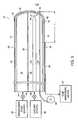
- FIG. 2is a longitudinal cross-sectional view of cryocatheter from a neuro-cryocatheter system of the present invention.
- FIG. 3is an axial cross-sectional view of the cryocatheter of FIG. 2 .
- FIGS. 4A-4Care schematic views of the cryocatheter showing a means for angling a distal tip portion of the cryocatheter.
- FIG. 5is a schematic view of a circuit for measuring sensory evoked potentials in a patient.
- FIG. 6is a dorsal view, in partial cutaway, of a portion of a spinal cord.
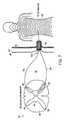
- FIG. 7is a composite schematic diagram showing the relationship between a spinal cord segment and its corresponding dermatome.
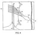
- FIG. 8is an enlarged dorsal view of the spinal cord of FIG. 6 showing the distal end of a cryocatheter located adjacent to a set of dorsal root filaments.
- FIG. 9Ais a partial dorsal view of a human body showing its dermatomes.
- FIG. 9Bis a partial ventral view of a human body showing its dermatomes.
- the highly structured neuroaxislends itself to cryoanalgesia techniques to produce analgesia or anesthesia of body parts innervated by the target nerve tissue. This is accomplished by selective cooling or freezing of the target neuronal tissue using a neurocryocatheter system to induce lesions along the neuroaxis.
- the neuro-cryocatheter systemis used to diagnose, monitor and interfere with nerve conduction along the spinal cord axis by invading the cerebrospinal fluid canal (subarachnoid space) by way of percutaneous puncture.
- the cooling or freezing of neuronal tissueproduces analgesia or anesthesia (i.e., “cryoanalgesia”) by impairing nerve conduction of the targeted neuronal tissue.
- the neuro-cryocatheter system of the present inventionmay be used not only on human patients but on other animals, particularly vertebrates, as well.
- the human spinal cordis functionally segmented along its length, giving rise to 30 pairs of spinal nerves.
- the skinis likewise segmented into dermatomes (see FIGS. 9 A and 9 B).
- a dermatomeis an area of skin contributing sensory afferent nerve fibers to a corresponding spinal cord segment.
- the skin (and deeper structures) and the spinal cordare connected by neurons (primary sensory or afferent neurons) which have sensory receptor endings, including pain receptors in the skin (and deeper structures).
- the bodies of the primary sensory nervesare found in the dorsal root ganglion, just inside the dural lining of the spinal canal.
- a nerve impulsetravels over the primary neuron, entering the spinal cord at the corresponding segment by way of the dorsal root nerve filaments.
- the neuron that transmits the impulseconnects the dermatome to its corresponding spinal cord segment.
- These filamentsare longitudinally arranged along the cord as shown in FIG. 6 . In the aggregate, these filaments combined are called a dorsal root.
- the axons of sensory neuronsterminate on secondary nerve cell bodies (gray matter) found in the dorsal horn of the spinal cord itself.
- the ventral horn of the spinal cordis composed of neuronal bodies of nerves providing enervation of muscles.
- the axons of motor neuronsleave the spinal cord becoming the ventral nerve root filaments.
- the ventral nerve root filaments and the dorsal nerve filamentsare separated by the denticulate ligaments.
- the ventral nerve filamentsjoin to form a mixed nerve that travels to the periphery of the body. Mixed nerves therefore carry sensory nerve impulses into the cord and motor nerve impulses away from the cord.
- Impairing nerve conduction in a mixed nerveimpairs both sensory and motor function. Impairing ventral nerve filaments alone impairs only motor function. Impairing dorsal nerve filaments alone impairs only sensory function.
- Neuronsare composed of cell bodies (nerve bodies) and appendages (axons and dendrites).
- Cell bodiescontain the cell nucleus and other structures essential for the life of the neuron.
- Axonsare extensions of the neuronal cell body of variable length (sometimes a meter long) that conduct electrochemical nerve impulses from the skin (and deeper structures) sensory receptors to the spinal cord where, after entering the cord they synapse on secondary nerve bodies found in the dorsal horn.
- Axons in the aggregateform nerve filaments.
- the nerve bodies of the primary sensory neuronsare found in the dorsal ganglion.
- the dorsal ganglionis a collection of nerve bodies found just inside the dura, lateral to the spinal cord and proximal to the formation of the mixed spinal nerve. It should be stressed that the dorsal nerve filaments are formed of aggregates of the axons of the sensory nerves coming from specific dermatomes (and related deeper structures) and going to specific segments of the spinal cord.
- axonsare within a fine tube of connective tissue called the endoneureon. If axons are destroyed, they will regenerate over time (weeks to months) and resume functioning, as long as the endoneureon tube remains intact, and the nerve cell body remains intact. Freezing axons destroys them, but leaves the endoneureon intact. Freezing nerve cell bodies irreversibly destroys the nerve by killing the cell body. Axons cannot regenerate if the cell body is destroyed. Cooling cell bodies or axons to about 0-20 degrees centigrade causes a reversible cessation of nerve transmission. (See: A.
- Vania Apkarian et al.A Cryogenic Device for Reversibly Blocking Transmission Through Small Regions of the Spinal Cord White Matter , Journal of Neuroscience Methods, 29 (1989) pp. 93-106, and Linqiu Zhou et al., Mechanism Research of Cryoanalgesia , Neurological Research, Vol. 17, August 1995, pp. 307-311.) This interruption in function may last for minutes to hours.
- the present inventionprovides prolonged relief of pain through selection of appropriate neuronal targets and freezing those targets to temperatures that result in prolonged impairment of neuronal function.
- Dorsal root nerve filamentsare appropriate targets for such relief of chronic pain.
- Candidate dermatomes and corresponding dorsal nerve root filamentsare determined by the clinical pain pattern.
- FIGS. 1-4show a neuro-cryocatheter system for the cooling or freezing of neuroaxis structure targets.
- the systemincludes an introducer 10 shown in FIG. 1 .
- the introducer 10comprises a stylet 12 encased by a sheath 14 .
- the stylet 12has a sharp, pointed tip 16 capable of penetrating soft tissue overlying the spinal canal.
- the introducer 10has an outer diameter of about 1.5 millimeters or less and a length of typically 4-5 inches.
- FIGS. 2 and 3show a cryocatheter 18 for insertion into the sheath 14 after the sheath 14 has been positioned in the patient's body.
- the cryocatheter 18has a diameter small enough to fit into the sheath 14 and has a length of about 6-36 inches.
- the cryocatheter 18includes a catheter body 20 in the form of a hollow outer tube having a distal end 22 that is insertable through the positioned sheath 14 and a proximate end 24 that remains outside of the body.
- the outer tube 20is shown as having a circular cross-section, it should be noted that the present invention is not so limited and the cryocatheter 18 can have a variety of configurations.
- the catheter body or outer tube 20is made of a non-rigid material and is thermally insulated with a coating 26 of insulating material.
- a septum 28is formed inside the outer tube 20 and extends the length thereof to divide the tube interior into first and second chambers 30 and 32 .
- the section thereof encompassing the first chamber 30will correspond to the dorsal or posterior side of the cryocatheter 18
- the section encompassing the second chamber 32will correspond to the ventral or anterior side of the cryocatheter 18 .
- the cryocatheter 18thus has a dorsal side 34 and a ventral side 36 .
- the cryocatheter 18is preferably made, at least in part, of a material suitable for radiologic imaging.
- the outer tube 20has an expandable portion 37 formed at the distal end 22 , on the dorsal side 34 so as to be in fluid communication with the first chamber 30 .
- the expandable portion 37comprises a section of expandable material formed in the outer tube 20 .
- the remainder of the outer tube 20is made of a material that is not expandable, or at least not as expandable as the material of the expandable portion 37 .
- a pressurized fluid source 38is connected with the first chamber 30 via a valve 40 .
- the valve 40can be operated to allow pressurized fluid from the source 38 to flow into the first chamber 30 and inflate the expandable portion 37 so that the distal end 22 is larger in cross-section than the rest of the outer tube 20 .
- the valve 40can also be operated to allow pressurized fluid to escape from the first chamber 30 so that the expandable portion 37 deflates.
- the outer tube 20includes a tip member 42 formed on the external surface of the ventral side 36 , at the distal end 22 .
- the tip member 42is made of an electrically conducting material and is not thermally insulated. That is, the coating 26 does not cover the tip member 42 .
- a coolant delivery tube 44is disposed in the second chamber 32 , preferably coaxial therewith.
- One or more expansion openings 45are formed in the distal end of the coolant delivery tube 44 , which is located adjacent to the distal end 22 of the outer tube 20 and the tip member 42 .
- the proximate end of the coolant delivery tube 44is connected to a source of pressurized coolant fluid (gas or liquid) 46 via another valve 48 .
- the pressurized coolant fluidflows, under control of the valve 48 , down the coolant delivery tube 44 and exits through the expansion opening(s) 45 into the second chamber 32 .
- the coolant fluidexpands and cools as it is discharged through the expansion opening(s) 45 .
- the spent coolant fluidflows back through the second chamber 32 and exits through the proximate end 24 in a manner known in the art.
- the present inventionis not limited to a catheter body comprising a single tube separated into two chambers by a septum.
- Another possible configurationincludes a catheter body formed from two catheters joined together lengthwise. One of the catheters would be an expandable catheter corresponding to the dorsal side 34 ; the other catheter would be a cryocatheter corresponding to the ventral side 36 .
- the geometry of the tip member 42will be determined based on the location and nature of the anatomic target site to be treated, which are discussed in more detail below.
- the tip member 42has a substantially semi-cylindrical shape, as shown in FIG. 2 .
- the length, L, of the tip member 42(FIG. 3) will be dependent on the anatomic target site to be treated. For example, given the arrangement of afferent filaments entering the dorsal horn (i.e., filaments may enter over several centimeters of the cord for a single nerve), the tip member length would be approximately equal to this length if the nerve filaments are the target. If the target were a dorsal ganglion, a shorter, smaller diameter tip member 42 would be desirable. If the entire posterior cord were to be treated, a longer tip member would be used. If generalized cooling of a substantial part or segment of the cord itself is desired (as to induce spinal anesthesia), then the tip member 42 would be configured to accommodate that objective.
- a temperature detector 50is located on the external surface of the tip member 42 .
- the temperature detector 50which can be any suitable device such as a thermocouple, can be used to provide feedback, via electric wire 51 connected to an external temperature monitoring device 52 , of the tip member temperature during a treatment procedure so that the flow of coolant fluid can be controlled accordingly to obtain the desired temperature.
- the cryocatheter 18optionally includes a hollow conduit 54 disposed inside the second chamber 32 of the outer tube 20 , adjacent to the coolant delivery tube 44 .
- the hollow conduit 54has a distal needle tip 56 and is movable longitudinally within the outer tube 20 by a rotatable head 58 located outside of the tube 20 and attached to the proximate end of the hollow conduit 54 .
- the needle tip 56can be extended beyond the distal end 22 (as shown in FIG. 3) or retracted back into the outer tube 20 by turning the rotatable head 58 in the appropriate direction.
- the head 58can be calibrated so as to indicate how much the needle tip 56 is extended. With the needle tip 56 extended, the hollow conduit 54 can be used for local injections of pharmaceuticals.
- the hollow conduit 54could be used diagnostically to verify the proper location of the distal end 22 . That is, once the distal end 22 was believed to be located at the desired target site, a small dose of an analgesic drug could be injected via the hollow conduit 54 . If the patient experienced pain relief in the affected part, this would indicate that the distal end 22 and the tip member 42 are properly located. As an alternative embodiment, it is possible to use a catheter tip configured to deliver pharmaceuticals in gel form.
- the cryocatheter 18optionally includes a means for changing the angle of a distal tip portion 59 of the cryocatheter 18 relative to the rest of the cryocatheter 18 .
- a tip angle changing meansis illustrated schematically in FIGS. 4A-4C.
- two guide wires 60 a and 60 bare disposed inside the outer tube 20 on diametrically opposing sides thereof. As seen in FIG. 2, the guide wires 60 a and 60 b are located adjacent to the opposing sides of the septum 28 so as to provide for lateral adjustment of the tip angle.
- the distal end of each guide wire 60 a and 60 bis fixedly attached to the distal tip portion 59 of the outer tube 20 .
- a first rotatable head 62 ais located outside of the tube 20 and is attached to the proximal end of the first guide wire 60 a
- a second rotatable head 62 bis located outside of the tube 20 and is attached to the proximal end of the second guide wire 60 b
- the first and second rotatable heads 62 a and 62 bare rotatively mounted to a handle (not shown) and have first and second levers 64 a and 64 b , respectively, formed thereon.
- the levers 64 a and 64 bare positioned such that a user holding the handle can manipulate the levers 64 a and 64 b independently to turn the corresponding rotatable head 62 a and 62 b .
- first and second heads 62 a and 62 bin the appropriate direction will pull the corresponding guide wire 60 a and 60 b relative to the outer tube 20 . Because the far end of each guide wire 60 a and 60 b is fixedly attached to the distal tip portion 59 , pulling one of the guide wires 60 a and 60 b causes the distal tip portion 59 to bend relative to the rest of the outer tube 20 .
- the catheter structuresare all made of a flexible material.
- pulling the first guide wire 60 acauses the distal tip portion 59 to bend to the left as shown in FIG. 4B
- pulling the second guide wire 60 bcauses the distal tip portion 59 to bend to the right as shown in FIG. 4 C.
- the rotatable heads 62 a and 62 bare calibrated so that the tip angle can be accurately controlled. Adjusting the tip angle permits the tip member 42 to be positioned adjacent to a wider range of neuroaxis targets.
- the tip member 42is electrically conducting and can thus function as an electrode for electrodiagnostic purposes. This is accomplished using sensory evoked potentials, which are central nervous system electrical potentials that have traditionally been measured from scalp electrodes after a stimulus is applied to a peripheral nerve or a dermatome.
- a dermatomeis an area of skin contributing sensory afferent nerve fibers to a spinal nerve(s); there is an anatomic correspondence between a given dermatome and a given dorsal nerve root.
- evoked potentials as currently measuredare remote from the stimulus and are the result of multiple neuronal interactions, they are small in amplitude and difficult to measure above background noise using conventional equipment.
- FIG. 5schematically shows the cryocatheter 18 positioned in a patient's neuroaxis 66 .
- a monitoring/stimulating device 70is electrically connected to the tip member 42 (functioning as an electrode) via a first electrical lead 72 that passes through the cryocatheter 18 .
- An external electrode 74is applied to the exterior of the patient's body, on the dermatome that corresponds to the desired neuronal target site in the neuroaxis.
- the external electrode 74is electrically connected to the monitoring/stimulating device 70 via a second electrical lead 76 .
- the monitoring/stimulating device 70is capable of generating an electrical stimulus for stimulating nerve endings of a dermatome.
- the monitoring/stimulating device 70is also capable of receiving signals from the tip member 42 and measuring and displaying evoked potentials in response to such signals. Many devices for measuring and displaying evoked potentials are commercially available.
- the monitoring/stimulating device 70can be any device suitable for such use, including commercially available devices, except that the device 70 will be used with the tip member 42 as the detecting electrode instead of a conventional scalp electrode.
- a measured electrical stimulusis applied to the corresponding dermatome via the external electrode 74 .
- This electrical stimuluswill be conducted centrally by the corresponding sensory (afferent) nerve 68 , including the target neuronal tissue, to the spinal cord. If the tip member 42 is in contact with the appropriate target neuronal tissue, an electrical circuit will be completed. That is, the electrical stimulus will be conducted from the monitoring/stimulating device 70 to the external electrode 74 via the second electrical lead 76 , from the external electrode 74 to the tip member 42 via the sensory (afferent) nerve 68 , and from the tip member 42 to the monitoring/stimulating device 70 via the first electrical lead 72 .
- the monitoring/stimulating device 70thus provides detection of the dermatomal sensory evoked potential when the tip member 42 is properly located.
- the design of the cryocatheter 18which provides for direct contact of the tip member 42 with the target neuronal tissue (as opposed to an electrode on the patient's scalp), greatly enhances the magnitude, sensitivity and specificity of the dermatomal sensory evoked potential.
- the device 70detects a sensory evoked potential, this serves as an indication that the tip member 42 is properly positioned.
- the cooling/freezing treatment of the target sitecan be carried out.
- nerve conductionwill be interrupted (before freezing) and thereby eliminate or reduce pain.
- nerve conduction interruptionwill also result in cessation of the sensory evoked potential.
- induced functional impairment of the target neuronal tissuewill be confirmed when the device 70 ceases to measure a sensory evoked potential. This further verifies that the tip member 42 has been properly positioned and means that protracted cooling or freezing can be carried out to complete the procedure.
- the neuro-cryocatheter systemprovides cryoanalgesia by cooling or freezing of neuroaxis structure targets. Cooling mixed nerves produces a nerve conduction block wherein motor function is affected before sensory function. Selection of sensory, dorsal nerve structures as targets for cooling/freezing will render this irrelevant.
- the motor functionis in the ventral nerve root, separated from the dorsal root by the denticulate ligament. Large myelinated sensory (afferent) fibers are affected and cease conduction before unmyelinated fibers. Small diameter myelinated fibers appear to be the most sensitive to cold. The most common neuronal tissue associated with pain is a small diameter unmyelinated fiber in the dorsal root.
- the nerve conduction blockWhen cooling neuronal tissue, the nerve conduction block is complete above 0 degrees centigrade, but prolonged conduction disturbances occur only by achieving temperatures of ⁇ 5 to ⁇ 20 degrees centigrade. At temperatures between ⁇ 5 and ⁇ 20 degrees centigrade neuropraxis may occur without neuronal destruction. Freezing generally occurs at temperatures below ⁇ 20 degrees centigrade. Once freezing has occurred, no benefit is obtained by achieving by lower temperatures. There is little inflammatory response to freezing and if tissue structures (for example, the endoneurium) are not disrupted, nerve regeneration is possible. Recovery from freezing is accomplished in cases where axon destruction is followed by axonal regeneration. This process of regeneration has been studied and reported in medical literature.
- cryocatheter 18is introduced into the subarachnoid space of the spinal canal (dorsal aspect) by percutaneous spinal canal puncture. Specifically, after skin preparation, the introducer 10 is inserted into the subarachnoid space at the desired location, and the stylet 12 is removed, leaving the sheath 14 in place to function as a cannula. The structure of the meninges is such that the subarachnoid space can be entered posteriorly, by percutaneous puncture between the spinous processes.
- the distal end 22 of the cryocatheter 18is inserted through the sheath 14 and into the subarachnoid space on the dorsal side of the spinal cord.
- the cryocatheter 18is oriented such that the expandable portion 37 faces the dorsal dura mater and the tip member 42 faces the dorsal side of the spinal cord.
- the distal end 22and hence the tip member 42 , are advanced to the target neuronal tissue. Proper positioning of the distal end 22 can be accomplished with imaging guidance. For instance, providing the cryocatheter 18 with a radio-opaqueness allows the distal end 22 to be placed adjacent to the target neuronal tissue with the aid of radiological imaging.
- the cryocatheter 18could also be made of non-magnetic (non-polarizable) material for use in an open MRI device.
- the external electrode 74is placed on the patient's body, on the dermatome that corresponds to the target neuronal tissue, and the device 70 is turned on such that the electrodiagnostic function of the cryocatheter 18 is operating.
- FIG. 6which is a dorsal view of a portion of a spinal cord 78 with the arachnoid mater 80 and the dura mater 82 shown pulled back
- FIG. 7which is a composite diagram of a spinal cord segment and its corresponding dermatome
- the spinal cord 78is comprised of the interior gray matter 84 and the white matter 86 , which encompasses the gray matter 84 .
- the gray matter 84includes two ventral horns 88 and two dorsal horns 90 .
- the arachnoid mater 80completely surrounds the spinal cord 78 , and the dura mater 82 surrounds the arachnoid mater 80 .
- the subarachnoid space 91lies between the spinal cord 78 and the arachnoid mater 80 .
- Each spinal nerve 92is divided into dorsal root filaments 94 and ventral root filaments 96 within the subarachnoid space 91 .
- the dorsal root filaments 94which are composed of sensory nerve fibers, enter the dorsal horn 90 of the spinal cord 78 .
- the ventral root filaments 96which are composed of motor nerve elements, emanate from the ventral horn 88 .
- the anatomic separationis accentuated by the denticulate ligament 98 , which lies between the dorsal root filaments 94 and the ventral root filaments 96 .
- the nerve root filamentsare made up of nerve axons.
- the nerve root filaments 94 and 96are represented by single axons in FIG. 7 .
- Dorsal axonsextend to the dermatome 99 that corresponds to the respective spinal cord segment, as shown in FIG. 7 .
- Ventral axonsextend to a corresponding muscle (not shown).
- the dorsal root ganglia 100(represented by a single nerve cell body in FIG. 7 ), which lie lateral of the dorsal root filaments 94 in the subarachnoid space 91 , contain the neuronal bodies of most of the afferent nerve axons. With the exception of the head, the dorsal root filaments 94 of the paired spinal nerves 92 supply the major sensory input of the body.
- the dorsal root filaments 94are a primary target for cooling or freezing. Because these are sensory nerve structures, interrupting conduction by cooling or freezing will reduce or eliminate pain that would otherwise be transmitted by the nerve structures.
- the ventral root elements 96(which are separated from the dorsal root elements by the denticulate ligament) are concerned with motor function and generally are not targets for the relief of pain.
- Other possible targetsinclude the dorsal root ganglia 100 , which contain the neuronal cell bodies of the dorsal root elements, and the dorsal horn 90 (particularly Rexed levels 1 - 4 , or even Rexed levels 1 - 5 ). Lissauer's tract, which is adjacent to the dorsal horn 90 , is also a potential target for cooling or freezing.
- Visceral afferent nerve fibers conducting pain signalsalso enter the spinal cord via the dorsal roots.
- the dorsal root neuronal elements or the dorsal horn non-functional (non-conductive) along the cord at various levelsboth visceral and peripheral nerve sensory afferents can be controlled. It should therefore be possible to alleviate pain in viscera by cooling or freezing the appropriate spinal targets. For example, pancreatic pain could be alleviated this way.
- the distal end 22 of the cryocatheter 18is inserted into the subarachnoid space and advanced until the tip member 42 is adjacent to the target neuronal tissue.
- the distal end 22is schematically shown as being adjacent to a set of dorsal root filaments 94 in FIG. 6 .
- FIG. 8shows the location of the distal end 22 relative to the dorsal root filaments 94 in more detail.
- the dorsal expandable portion 37 of the cryocatheter 18is inflated with pressurized fluid from the source 38 , as controlled by the valve 40 , until it expands into contact with the arachnoid mater 80 and the adjacent dura mater 82 and presses the tip member 42 on the ventral surface of the cryocatheter 18 into contact with the dorsal neuronal target.
- inflation of the expandable portion 37holds the distal end 22 in position relative to the target neuronal tissue.
- reception of dermatomal sensory evoked potentials by the device 70indicates that the tip member 42 is properly positioned.
- the valve 48is opened to admit a flow of coolant fluid to the coolant delivery tube 44 .
- the coolant fluidexits the tube 44 via the opening(s) 45 , expands, and thereby cools the tip member 42 .
- the temperature of the tip member 42is monitored by the temperature detector 50 . By monitoring the tip member temperature, the operator will be able to control the flow of coolant fluid so as to gradually cool the tip member 42 , and hence the neuronal target tissue. Functional impairment of the target neuronal tissue induced by cooling or freezing will be confirmed by cessation of the dermatomal evoked sensory potential measured by the device 70 .
- the neuronal tissuewill be cooled or frozen. If cooled, the procedure may be carried out for extended periods of time. If neuronal tissue is frozen, continued application of the freezing process beyond that necessary to achieve at least ⁇ 20 degrees centigrade is unnecessary.
- cryocatheter 18is being used for diagnostic purposes only (i.e., being used to determine the functional status of neuronal tissue)
- the procedureis the same as that described above except that the cooling/freezing steps are omitted and the diagnostic information would be obtained by measuring dermatomal sensory evoked potentials off the neuronal tissue while stimulating the appropriate dermatome.
- the use of this functioncould maintain spinal cord function during neurosurgery.
- the affect of cooling or freezing of neuroaxis tissuewill be impacted by the particular anatomic site chosen (the target neuronal tissue), the rate of cooling or freezing, the temperature achieved, the duration of cooling in some circumstances, and thawing/freezing cycles, if employed.
- Thiwing/freezing cyclesrefers to small ice crystals thawing and the water being subsequently refrozen by larger ice crystals.
- Freezingresults in the withdrawing of water from biologic systems and the deposition of water in ice crystals. The development of ice crystals depends upon a) crystal nucleation rate and b) the ice crystal growth rate. Both of these factors are dependent on temperature and the rate of cooling. These factors are also tissue type specific and may not be linear with fall in temperature.
- the location of the ice crystalsis dependent on the rate of cooling, with rapid freezing promoting the formation of intracellular ice crystals and increasing the risk of ultimate cell death.
- the size of the crystals for a given amount of water (in tissue)is a function of the number of crystals initiated by the process.
- the rate of temperature fallmay well be a dominant variable. This in turn will be a function of efficiency by which a system removes heat.
- Anatomic considerations, such as blood vessel supply (blood flow) and cerebrospinal flow rates,may well impact the cooling rate. Recrystallization (i.e., the growth of large crystals at the expense of smaller ones) will influence the final nature and the extent of tissue damage and may occur during thawing. Thawing/freezing cycles, if employed, will impact the final lesion.
- the geometry of the tip member 42is a factor in lesion production since the tissue immediately adjacent to the tip member 42 will freeze more quickly and thoroughly. Moreover, the size of the ice ball, a field of cooling gradients, is correlated to the tip geometry. This could result in intracellular ice near the tip member 42 and extracellular ice away from the tip member 42 . In any event, it is anticipated that there will be a freezing gradient related to the tip member 42 and its configuration.
- Neuronal cell death(as opposed to axonal disruption) is likely to occur when a critical temperature achieved. This is believed to be ⁇ 4 degrees centigrade or below and certainly is reached at ⁇ 20 degrees centigrade. This temperature may be somewhat tissue dependent (for example, red blood cell versus neuronal tissue). There are reports of neuronal recovery for temperatures as low as ⁇ 15 degrees centigrade. However, there appears to be a consensus that cells do not survive at temperatures lower than ⁇ 20 degrees centigrade. Neuronal generation and conduction of nerve electropotentials ceases during cooling, but before nerve tissue is frozen. In addition, the electrical impedance of the tip member 42 goes up as ice is formed on it. Controlled cooling of the tip member 42 and the target tissue can avoid this and allow sensory evoked potential measurement.
- axons or nerve bodiesare cooled, the return of function will return relatively quickly (i.e., over the course of many hours to several days). If axons are frozen, return of function will take many days or weeks as degeneration/regeneration of axons occur (axonal tissue regenerates at approximately 1-3 millimeters per day). If nerve bodies are frozen, neuronal function will generally not return. Accordingly, the target tissue should be selected carefully.
- An alternative embodiment to the neuro-cryocatheter system described abovewould be to provide the cryogenic, electrodiagnostic, and pharmaceutical delivery functions with two or more catheters rather than a single catheter.
- Such an alternative systemwould include an introducer the same as or similar to the introducer 10 of FIG. 1 and a plurality of catheters.
- a cryocatheterhaving cryogenic capabilities for cooling or freezing of neuroaxis structure targets and a separate catheter for delivering pharmaceuticals.
- Such a catheterwould be used for diagnostic purposes only (i.e., for determining the functional status of neuronal tissue).
Landscapes
- Health & Medical Sciences (AREA)
- Life Sciences & Earth Sciences (AREA)
- Surgery (AREA)
- Nuclear Medicine, Radiotherapy & Molecular Imaging (AREA)
- Animal Behavior & Ethology (AREA)
- General Health & Medical Sciences (AREA)
- Biomedical Technology (AREA)
- Heart & Thoracic Surgery (AREA)
- Medical Informatics (AREA)
- Molecular Biology (AREA)
- Veterinary Medicine (AREA)
- Engineering & Computer Science (AREA)
- Public Health (AREA)
- Otolaryngology (AREA)
- Neurology (AREA)
- Neurosurgery (AREA)
- Physics & Mathematics (AREA)
- Biophysics (AREA)
- Pathology (AREA)
- Thermotherapy And Cooling Therapy Devices (AREA)
Abstract
Description
Claims (18)
Priority Applications (4)
| Application Number | Priority Date | Filing Date | Title |
|---|---|---|---|
| US10/071,574US6761715B2 (en) | 2001-04-26 | 2002-02-05 | Method and device for neurocryo analgesia and anesthesia |
| AU2002258995AAU2002258995A1 (en) | 2001-04-26 | 2002-04-25 | Method and device for neurocryo analgesia and anesthesia |
| PCT/US2002/013018WO2002087653A2 (en) | 2001-04-26 | 2002-04-25 | Method and device for neurocryo analgesia and anesthesia |
| US10/857,402US7458968B2 (en) | 2001-04-26 | 2004-05-28 | Device for neurocryo analgesia and anesthesia |
Applications Claiming Priority (2)
| Application Number | Priority Date | Filing Date | Title |
|---|---|---|---|
| US28663601P | 2001-04-26 | 2001-04-26 | |
| US10/071,574US6761715B2 (en) | 2001-04-26 | 2002-02-05 | Method and device for neurocryo analgesia and anesthesia |
Related Child Applications (1)
| Application Number | Title | Priority Date | Filing Date |
|---|---|---|---|
| US10/857,402DivisionUS7458968B2 (en) | 2001-04-26 | 2004-05-28 | Device for neurocryo analgesia and anesthesia |
Publications (2)
| Publication Number | Publication Date |
|---|---|
| US20020161360A1 US20020161360A1 (en) | 2002-10-31 |
| US6761715B2true US6761715B2 (en) | 2004-07-13 |
Family
ID=26752392
Family Applications (2)
| Application Number | Title | Priority Date | Filing Date |
|---|---|---|---|
| US10/071,574Expired - LifetimeUS6761715B2 (en) | 2001-04-26 | 2002-02-05 | Method and device for neurocryo analgesia and anesthesia |
| US10/857,402Expired - Fee RelatedUS7458968B2 (en) | 2001-04-26 | 2004-05-28 | Device for neurocryo analgesia and anesthesia |
Family Applications After (1)
| Application Number | Title | Priority Date | Filing Date |
|---|---|---|---|
| US10/857,402Expired - Fee RelatedUS7458968B2 (en) | 2001-04-26 | 2004-05-28 | Device for neurocryo analgesia and anesthesia |
Country Status (3)
| Country | Link |
|---|---|
| US (2) | US6761715B2 (en) |
| AU (1) | AU2002258995A1 (en) |
| WO (1) | WO2002087653A2 (en) |
Cited By (64)
| Publication number | Priority date | Publication date | Assignee | Title |
|---|---|---|---|---|
| US20030014016A1 (en)* | 2001-07-13 | 2003-01-16 | Purdy Phillip D. | Methods and apparatuses for navigating the subaracnhnoid space |
| US20040215181A1 (en)* | 2003-04-25 | 2004-10-28 | Medtronic, Inc. | Delivery of fluid during transurethral prostate treatment |
| US20040220648A1 (en)* | 2001-04-26 | 2004-11-04 | Carroll Ronald J. | Device for neurocryo analgesia and anesthesia |
| US20070073354A1 (en)* | 2005-09-26 | 2007-03-29 | Knudson Mark B | Neural blocking therapy |
| US20070129714A1 (en)* | 2005-05-20 | 2007-06-07 | Echo Healthcare Llc | Subdermal cryogenic remodeling of muscles, nerves, connective tissue, and/or adipose tissue (FAT) |
| US20070179491A1 (en)* | 2006-01-31 | 2007-08-02 | Medtronic, Inc. | Sensing needle for ablation therapy |
| US20080082145A1 (en)* | 2006-09-29 | 2008-04-03 | Medtronic, Inc. | User interface for ablation therapy |
| US20080183164A1 (en)* | 2005-05-20 | 2008-07-31 | Myoscience, Inc. | Subdermal cryogenic remodeling of muscles, nerves, connective tissue, and/or adipose tissue (fat) |
| US20080269737A1 (en)* | 2007-04-26 | 2008-10-30 | Medtronic, Inc. | Fluid sensor for ablation therapy |
| US20080269862A1 (en)* | 2007-04-30 | 2008-10-30 | Medtronic, Inc. | Extension and retraction mechanism for a hand-held device |
| US20080275440A1 (en)* | 2007-05-03 | 2008-11-06 | Medtronic, Inc. | Post-ablation verification of lesion size |
| US20080312497A1 (en)* | 2007-06-14 | 2008-12-18 | Medtronic, Inc. | Distal viewing window of a medical catheter |
| US20090149911A1 (en)* | 2007-12-05 | 2009-06-11 | Searete Llc, A Limited Liability Corporation Of The State Of Delaware | System for electrical modulation of neural conduction |
| US20090149919A1 (en)* | 2007-12-05 | 2009-06-11 | Searete Llc, A Limited Liability Corporation Of The State Of Delaware | Method for thermal modulation of neural activity |
| US20090149912A1 (en)* | 2007-12-05 | 2009-06-11 | Searete Llc, A Limited Liability Corporation Of The State Of Delaware | Method for electrical modulation of neural conduction |
| US20090192557A1 (en)* | 2008-01-23 | 2009-07-30 | Whitehurst Todd K | Methods and systems of treating pancreatitis pain caused by sphincter of oddi dysfunction |
| US20090192558A1 (en)* | 2008-01-30 | 2009-07-30 | Whitehurst Todd K | Methods and systems of treating pancreatitis pain |
| US20090248001A1 (en)* | 2007-11-14 | 2009-10-01 | Myoscience, Inc. | Pain management using cryogenic remodeling |
| US20090299357A1 (en)* | 2006-04-24 | 2009-12-03 | Thomas Jefferson University | Cryoneedle and cryotheraphy system |
| US7662177B2 (en) | 2006-04-12 | 2010-02-16 | Bacoustics, Llc | Apparatus and methods for pain relief using ultrasound waves in combination with cryogenic energy |
| US7938822B1 (en) | 2010-05-12 | 2011-05-10 | Icecure Medical Ltd. | Heating and cooling of cryosurgical instrument using a single cryogen |
| US7967814B2 (en) | 2009-02-05 | 2011-06-28 | Icecure Medical Ltd. | Cryoprobe with vibrating mechanism |
| US7967815B1 (en) | 2010-03-25 | 2011-06-28 | Icecure Medical Ltd. | Cryosurgical instrument with enhanced heat transfer |
| US8080005B1 (en) | 2010-06-10 | 2011-12-20 | Icecure Medical Ltd. | Closed loop cryosurgical pressure and flow regulated system |
| US8083733B2 (en) | 2008-04-16 | 2011-12-27 | Icecure Medical Ltd. | Cryosurgical instrument with enhanced heat exchange |
| US8160695B2 (en) | 2007-12-05 | 2012-04-17 | The Invention Science Fund I, Llc | System for chemical modulation of neural activity |
| US8165669B2 (en) | 2007-12-05 | 2012-04-24 | The Invention Science Fund I, Llc | System for magnetic modulation of neural conduction |
| US8165668B2 (en) | 2007-12-05 | 2012-04-24 | The Invention Science Fund I, Llc | Method for magnetic modulation of neural conduction |
| US8162812B2 (en) | 2009-03-12 | 2012-04-24 | Icecure Medical Ltd. | Combined cryotherapy and brachytherapy device and method |
| US8180446B2 (en) | 2007-12-05 | 2012-05-15 | The Invention Science Fund I, Llc | Method and system for cyclical neural modulation based on activity state |
| US8180447B2 (en) | 2007-12-05 | 2012-05-15 | The Invention Science Fund I, Llc | Method for reversible chemical modulation of neural activity |
| US8255057B2 (en) | 2009-01-29 | 2012-08-28 | Nevro Corporation | Systems and methods for producing asynchronous neural responses to treat pain and/or other patient conditions |
| US8409185B2 (en) | 2007-02-16 | 2013-04-02 | Myoscience, Inc. | Replaceable and/or easily removable needle systems for dermal and transdermal cryogenic remodeling |
| US8801664B1 (en) | 2008-02-04 | 2014-08-12 | Robert J. Perry | Medical procedure kit |
| US8880167B2 (en)* | 2013-02-13 | 2014-11-04 | Flint Hills Scientific, Llc | Selective recruitment and activation of fiber types in nerves for the control of undesirable brain state changes |
| US9017318B2 (en) | 2012-01-20 | 2015-04-28 | Myoscience, Inc. | Cryogenic probe system and method |
| US9023022B2 (en) | 2013-03-15 | 2015-05-05 | Warsaw Orthopedic, Inc. | Nerve and soft tissue ablation device having release instrument |
| US9023023B2 (en) | 2013-03-15 | 2015-05-05 | Warsaw Orthopedic, Inc. | Nerve and soft tissue ablation device |
| US9033966B2 (en) | 2013-03-15 | 2015-05-19 | Warsaw Orthopedic, Inc. | Nerve and soft tissue ablation device |
| US9066712B2 (en) | 2008-12-22 | 2015-06-30 | Myoscience, Inc. | Integrated cryosurgical system with refrigerant and electrical power source |
| US9131975B2 (en) | 2013-03-15 | 2015-09-15 | Warsaw Orthopedic, Inc. | Nerve and soft tissue ablation device |
| US9155584B2 (en) | 2012-01-13 | 2015-10-13 | Myoscience, Inc. | Cryogenic probe filtration system |
| US9186197B2 (en) | 2013-03-15 | 2015-11-17 | Warsaw Orthopedic, Inc. | Nerve and soft tissue ablation device for treating pain |
| US9198707B2 (en) | 2013-03-15 | 2015-12-01 | Warsaw Orthopedic, Inc. | Nerve and soft tissue ablation device and method |
| US9241754B2 (en) | 2013-03-15 | 2016-01-26 | Warsaw Orthopedic, Inc. | Nerve and soft tissue ablation device |
| US9241753B2 (en) | 2012-01-13 | 2016-01-26 | Myoscience, Inc. | Skin protection for subdermal cryogenic remodeling for cosmetic and other treatments |
| US9254162B2 (en) | 2006-12-21 | 2016-02-09 | Myoscience, Inc. | Dermal and transdermal cryogenic microprobe systems |
| US9295512B2 (en) | 2013-03-15 | 2016-03-29 | Myoscience, Inc. | Methods and devices for pain management |
| US9314290B2 (en) | 2012-01-13 | 2016-04-19 | Myoscience, Inc. | Cryogenic needle with freeze zone regulation |
| US9597480B2 (en) | 2009-10-07 | 2017-03-21 | Endophys Holding, LLC | Intraluminal devices and systems |
| US9610112B2 (en) | 2013-03-15 | 2017-04-04 | Myoscience, Inc. | Cryogenic enhancement of joint function, alleviation of joint stiffness and/or alleviation of pain associated with osteoarthritis |
| US9668800B2 (en) | 2013-03-15 | 2017-06-06 | Myoscience, Inc. | Methods and systems for treatment of spasticity |
| US9788773B2 (en) | 2008-05-21 | 2017-10-17 | Robert J. Perry | Vein presentation enhancement device |
| US9895190B2 (en) | 2014-04-28 | 2018-02-20 | Warsaw Orthopedic, Inc. | Devices and methods for radiofrequency ablation having at least two electrodes |
| US9956355B2 (en) | 2015-03-26 | 2018-05-01 | The Regents Of The University Of Michigan | Applicator for cryoanesthesia and analgesia |
| US10130409B2 (en) | 2013-11-05 | 2018-11-20 | Myoscience, Inc. | Secure cryosurgical treatment system |
| US10631893B2 (en) | 2015-07-10 | 2020-04-28 | Warsaw Orthopedic, Inc. | Nerve and soft tissue removal device |
| US10888366B2 (en) | 2013-03-15 | 2021-01-12 | Pacira Cryotech, Inc. | Cryogenic blunt dissection methods and devices |
| US11134998B2 (en) | 2017-11-15 | 2021-10-05 | Pacira Cryotech, Inc. | Integrated cold therapy and electrical stimulation systems for locating and treating nerves and associated methods |
| US11311327B2 (en) | 2016-05-13 | 2022-04-26 | Pacira Cryotech, Inc. | Methods and systems for locating and treating nerves with cold therapy |
| US11633224B2 (en) | 2020-02-10 | 2023-04-25 | Icecure Medical Ltd. | Cryogen pump |
| US12215811B2 (en) | 2022-07-18 | 2025-02-04 | Icecure Medical Ltd. | Cryogenic system connector |
| US12296129B2 (en) | 2018-03-07 | 2025-05-13 | Soovu Labs, Inc. | Systems and methods for improved pain relief from stimulation of thermal fibers |
| US12426934B2 (en) | 2022-02-28 | 2025-09-30 | Icecure Medical Ltd. | Cryogen flow control |
Families Citing this family (15)
| Publication number | Priority date | Publication date | Assignee | Title |
|---|---|---|---|---|
| US20040122482A1 (en)* | 2002-12-20 | 2004-06-24 | James Tung | Nerve proximity method and device |
| US7444183B2 (en) | 2003-02-03 | 2008-10-28 | Enteromedics, Inc. | Intraluminal electrode apparatus and method |
| US7613515B2 (en) | 2003-02-03 | 2009-11-03 | Enteromedics Inc. | High frequency vagal blockage therapy |
| US7844338B2 (en)* | 2003-02-03 | 2010-11-30 | Enteromedics Inc. | High frequency obesity treatment |
| US20040172084A1 (en) | 2003-02-03 | 2004-09-02 | Knudson Mark B. | Method and apparatus for treatment of gastro-esophageal reflux disease (GERD) |
| US7672727B2 (en) | 2005-08-17 | 2010-03-02 | Enteromedics Inc. | Neural electrode treatment |
| US7822486B2 (en) | 2005-08-17 | 2010-10-26 | Enteromedics Inc. | Custom sized neural electrodes |
| US20080281365A1 (en)* | 2007-05-09 | 2008-11-13 | Tweden Katherine S | Neural signal duty cycle |
| US20100042461A1 (en)* | 2008-08-15 | 2010-02-18 | Sears Brands, Llc | Grouping service orders in an electronic services marketplace |
| WO2011075328A1 (en) | 2009-12-14 | 2011-06-23 | Mayo Foundation For Medical Education And Research | Device and method for treating cardiac disorders by modulating autonomic response |
| US20120089211A1 (en)* | 2010-04-08 | 2012-04-12 | Myoscience, Inc. | Methods and apparatus for cryogenically treating multiple tissue sites with a single puncture |
| US8825164B2 (en) | 2010-06-11 | 2014-09-02 | Enteromedics Inc. | Neural modulation devices and methods |
| WO2014172398A1 (en) | 2013-04-15 | 2014-10-23 | Mayo Foundation For Medical Education And Research | Method and apparatus for percutaneous epicardial ablation of cardiac ganglionated plexi without myocardial injury |
| PL3437579T3 (en) | 2017-08-04 | 2023-10-16 | Erbe Elektromedizin Gmbh | Cryosurgical instrument |
| EP4493091A4 (en)* | 2022-03-15 | 2025-05-21 | Baylis Medical Technologies Inc. | Probe, system, and method for forming a lesion in a target tissue |
Citations (28)
| Publication number | Priority date | Publication date | Assignee | Title |
|---|---|---|---|---|
| US3901241A (en) | 1973-05-31 | 1975-08-26 | Al Corp Du | Disposable cryosurgical instrument |
| US4202336A (en) | 1976-05-14 | 1980-05-13 | Erbe Elektromedizin Kg | Cauterizing probes for cryosurgery |
| US4306561A (en) | 1979-11-05 | 1981-12-22 | Ocean Trading Co., Ltd. | Holding apparatus for repairing severed nerves and method of using the same |
| EP0043447A2 (en) | 1980-06-13 | 1982-01-13 | Karl-Heinz Kreibel | Low-temperature transmission device for medical purposes |
| US4646735A (en) | 1985-10-04 | 1987-03-03 | Seney John S | Pain-alleviating tissue treatment assembly |
| US4802475A (en) | 1987-06-22 | 1989-02-07 | Weshahy Ahmed H A G | Methods and apparatus of applying intra-lesional cryotherapy |
| US4904237A (en)* | 1988-05-16 | 1990-02-27 | Janese Woodrow W | Apparatus for the exchange of cerebrospinal fluid and a method of treating brain and spinal cord injuries |
| US4936306A (en) | 1985-02-15 | 1990-06-26 | Doty James R | Device and method for monitoring evoked potentials and electroencephalograms |
| US5081990A (en) | 1990-05-11 | 1992-01-21 | New York University | Catheter for spinal epidural injection of drugs and measurement of evoked potentials |
| US5147355A (en) | 1988-09-23 | 1992-09-15 | Brigham And Womens Hospital | Cryoablation catheter and method of performing cryoablation |
| US5281215A (en) | 1992-04-16 | 1994-01-25 | Implemed, Inc. | Cryogenic catheter |
| US5281213A (en) | 1992-04-16 | 1994-01-25 | Implemed, Inc. | Catheter for ice mapping and ablation |
| US5314423A (en) | 1992-11-03 | 1994-05-24 | Seney John S | Cold electrode pain alleviating tissue treatment assembly |
| US5336176A (en)* | 1991-12-06 | 1994-08-09 | Inbae Yoon | Automatic retractable safety penetrating instrument |
| US5417686A (en) | 1990-07-10 | 1995-05-23 | The Texas A&M University System | Temperature control mechanisms for a micro heat pipe catheter |
| US5423807A (en) | 1992-04-16 | 1995-06-13 | Implemed, Inc. | Cryogenic mapping and ablation catheter |
| US5672172A (en) | 1994-06-23 | 1997-09-30 | Vros Corporation | Surgical instrument with ultrasound pulse generator |
| US5693077A (en) | 1994-09-21 | 1997-12-02 | Friedman; Mark H. | Treatment of vascular and tension headache atypical facial pain allergic rhinitis and cervical muscle hyperactivity |
| US5741248A (en) | 1995-06-07 | 1998-04-21 | Temple University-Of The Commonwealth System Of Higher Education | Fluorochemical liquid augmented cryosurgery |
| US5957963A (en) | 1998-01-23 | 1999-09-28 | Del Mar Medical Technologies, Inc. | Selective organ hypothermia method and apparatus |
| US6190370B1 (en)* | 1997-07-25 | 2001-02-20 | Arrow International, Inc. | Devices, systems and methods for determining proper placement of epidural catheters |
| US6217552B1 (en)* | 1999-03-01 | 2001-04-17 | Coaxia, Inc. | Medical device for selective intrathecal spinal cooling in aortic surgery and spinal trauma |
| US6254599B1 (en) | 1997-05-09 | 2001-07-03 | Atrionix, Inc. | Circumferential ablation device assembly |
| US6272370B1 (en)* | 1998-08-07 | 2001-08-07 | The Regents Of University Of Minnesota | MR-visible medical device for neurological interventions using nonlinear magnetic stereotaxis and a method imaging |
| US6364899B1 (en)* | 1998-01-23 | 2002-04-02 | Innercool Therapies, Inc. | Heat pipe nerve cooler |
| US20030014016A1 (en)* | 2001-07-13 | 2003-01-16 | Purdy Phillip D. | Methods and apparatuses for navigating the subaracnhnoid space |
| US6551349B2 (en)* | 1998-03-24 | 2003-04-22 | Innercool Therapies, Inc. | Selective organ cooling apparatus |
| US20030130651A1 (en)* | 2001-12-31 | 2003-07-10 | Lennox Charles D. | Uniform selective cerebral hypothermia |
Family Cites Families (6)
| Publication number | Priority date | Publication date | Assignee | Title |
|---|---|---|---|---|
| US5108390A (en) | 1988-11-14 | 1992-04-28 | Frigitronics, Inc. | Flexible cryoprobe |
| US5624392A (en)* | 1990-05-11 | 1997-04-29 | Saab; Mark A. | Heat transfer catheters and methods of making and using same |
| US5626618A (en)* | 1993-09-24 | 1997-05-06 | The Ohio State University | Mechanical adjunct to cardiopulmonary resuscitation (CPR), and an electrical adjunct to defibrillation countershock, cardiac pacing, and cardiac monitoring |
| US6235019B1 (en)* | 1997-02-27 | 2001-05-22 | Cryocath Technologies, Inc. | Cryosurgical catheter |
| US6551274B2 (en)* | 2000-02-29 | 2003-04-22 | Biosense Webster, Inc. | Cryoablation catheter with an expandable cooling chamber |
| US6761715B2 (en)* | 2001-04-26 | 2004-07-13 | Ronald J. Carroll | Method and device for neurocryo analgesia and anesthesia |
- 2002
- 2002-02-05USUS10/071,574patent/US6761715B2/ennot_activeExpired - Lifetime
- 2002-04-25AUAU2002258995Apatent/AU2002258995A1/ennot_activeAbandoned
- 2002-04-25WOPCT/US2002/013018patent/WO2002087653A2/ennot_activeApplication Discontinuation
- 2004
- 2004-05-28USUS10/857,402patent/US7458968B2/ennot_activeExpired - Fee Related
Patent Citations (33)
| Publication number | Priority date | Publication date | Assignee | Title |
|---|---|---|---|---|
| US3901241A (en) | 1973-05-31 | 1975-08-26 | Al Corp Du | Disposable cryosurgical instrument |
| US4202336A (en) | 1976-05-14 | 1980-05-13 | Erbe Elektromedizin Kg | Cauterizing probes for cryosurgery |
| US4306561A (en) | 1979-11-05 | 1981-12-22 | Ocean Trading Co., Ltd. | Holding apparatus for repairing severed nerves and method of using the same |
| EP0043447A2 (en) | 1980-06-13 | 1982-01-13 | Karl-Heinz Kreibel | Low-temperature transmission device for medical purposes |
| US4936306A (en) | 1985-02-15 | 1990-06-26 | Doty James R | Device and method for monitoring evoked potentials and electroencephalograms |
| US4646735A (en) | 1985-10-04 | 1987-03-03 | Seney John S | Pain-alleviating tissue treatment assembly |
| US4802475A (en) | 1987-06-22 | 1989-02-07 | Weshahy Ahmed H A G | Methods and apparatus of applying intra-lesional cryotherapy |
| US4904237A (en)* | 1988-05-16 | 1990-02-27 | Janese Woodrow W | Apparatus for the exchange of cerebrospinal fluid and a method of treating brain and spinal cord injuries |
| US5147355A (en) | 1988-09-23 | 1992-09-15 | Brigham And Womens Hospital | Cryoablation catheter and method of performing cryoablation |
| US5081990A (en) | 1990-05-11 | 1992-01-21 | New York University | Catheter for spinal epidural injection of drugs and measurement of evoked potentials |
| US5417686A (en) | 1990-07-10 | 1995-05-23 | The Texas A&M University System | Temperature control mechanisms for a micro heat pipe catheter |
| US5591162A (en)* | 1990-07-10 | 1997-01-07 | The Texas A&M University System | Treatment method using a micro heat pipe catheter |
| US5423770A (en)* | 1991-12-06 | 1995-06-13 | Yoon; Inbae | Automatic retractable safety penetrating instrument |
| US5336176A (en)* | 1991-12-06 | 1994-08-09 | Inbae Yoon | Automatic retractable safety penetrating instrument |
| US5423807A (en) | 1992-04-16 | 1995-06-13 | Implemed, Inc. | Cryogenic mapping and ablation catheter |
| US5281213A (en) | 1992-04-16 | 1994-01-25 | Implemed, Inc. | Catheter for ice mapping and ablation |
| US5281215A (en) | 1992-04-16 | 1994-01-25 | Implemed, Inc. | Cryogenic catheter |
| US5314423A (en) | 1992-11-03 | 1994-05-24 | Seney John S | Cold electrode pain alleviating tissue treatment assembly |
| US6106517A (en) | 1994-06-23 | 2000-08-22 | Situs Corporation | Surgical instrument with ultrasound pulse generator |
| US5672172A (en) | 1994-06-23 | 1997-09-30 | Vros Corporation | Surgical instrument with ultrasound pulse generator |
| US5693077A (en) | 1994-09-21 | 1997-12-02 | Friedman; Mark H. | Treatment of vascular and tension headache atypical facial pain allergic rhinitis and cervical muscle hyperactivity |
| US5741248A (en) | 1995-06-07 | 1998-04-21 | Temple University-Of The Commonwealth System Of Higher Education | Fluorochemical liquid augmented cryosurgery |
| US6254599B1 (en) | 1997-05-09 | 2001-07-03 | Atrionix, Inc. | Circumferential ablation device assembly |
| US6190370B1 (en)* | 1997-07-25 | 2001-02-20 | Arrow International, Inc. | Devices, systems and methods for determining proper placement of epidural catheters |
| US6364899B1 (en)* | 1998-01-23 | 2002-04-02 | Innercool Therapies, Inc. | Heat pipe nerve cooler |
| US6051019A (en) | 1998-01-23 | 2000-04-18 | Del Mar Medical Technologies, Inc. | Selective organ hypothermia method and apparatus |
| US5957963A (en) | 1998-01-23 | 1999-09-28 | Del Mar Medical Technologies, Inc. | Selective organ hypothermia method and apparatus |
| US6551349B2 (en)* | 1998-03-24 | 2003-04-22 | Innercool Therapies, Inc. | Selective organ cooling apparatus |
| US6272370B1 (en)* | 1998-08-07 | 2001-08-07 | The Regents Of University Of Minnesota | MR-visible medical device for neurological interventions using nonlinear magnetic stereotaxis and a method imaging |
| US6217552B1 (en)* | 1999-03-01 | 2001-04-17 | Coaxia, Inc. | Medical device for selective intrathecal spinal cooling in aortic surgery and spinal trauma |
| US6379331B2 (en)* | 1999-03-01 | 2002-04-30 | Coaxia, Inc. | Medical device for selective intrathecal spinal cooling in aortic surgery and spinal trauma |
| US20030014016A1 (en)* | 2001-07-13 | 2003-01-16 | Purdy Phillip D. | Methods and apparatuses for navigating the subaracnhnoid space |
| US20030130651A1 (en)* | 2001-12-31 | 2003-07-10 | Lennox Charles D. | Uniform selective cerebral hypothermia |
Non-Patent Citations (4)
| Title |
|---|
| A. Vania Apkarian, et al., A cryogenic device for reversibly blocking transmission through small regions of the spinal cord white matter, Journal of Neuroscience Methods, Feb. 1989, p. 93-106, 29, Elsevier Science Publishers B.V. (Biomedical Division), Syracuse, NY. |
| Francis Robiscsek, MD, et al, Biological thersholds of cold-induced phrenic nerve injury, The Journal of Thoracic and Cardiovascular Surgery, Jan. 1990, p. 167-170, vol. 99 No. 1. |
| Linqui Zhou, et al., Mechanism research of cryoanalgesia, Neurological Research, Aug. 1995, p. 307-311, vol. 17, Forefront Publishing Group. |
| P. J. D. Evans, Cryoanalgesia, The application of low temperatures to nerves to produce anesthesia or analgesia, Anesthesia, 1981, vol. 36, pp. 1003-1013. |
Cited By (150)
| Publication number | Priority date | Publication date | Assignee | Title |
|---|---|---|---|---|
| US7458968B2 (en)* | 2001-04-26 | 2008-12-02 | Carroll Ronald J | Device for neurocryo analgesia and anesthesia |
| US20040220648A1 (en)* | 2001-04-26 | 2004-11-04 | Carroll Ronald J. | Device for neurocryo analgesia and anesthesia |
| US10716921B2 (en) | 2001-07-13 | 2020-07-21 | Endophys Holdings, Llc | Methods of using a dual-lumen sheath in intraluminal procedures |
| US8961452B2 (en) | 2001-07-13 | 2015-02-24 | Board Of Regents, The University Of Texas System | Multi-sheath member apparatus |
| US10315013B2 (en) | 2001-07-13 | 2019-06-11 | Endophys Holdings, Llc | Sheath with sensing capabilities |
| US8131353B2 (en) | 2001-07-13 | 2012-03-06 | Board Of Regents, The University Of Texas System | Methods and apparatuses for navigating the subarachnoid space |
| US20030014016A1 (en)* | 2001-07-13 | 2003-01-16 | Purdy Phillip D. | Methods and apparatuses for navigating the subaracnhnoid space |
| US20100324397A1 (en)* | 2001-07-13 | 2010-12-23 | Purdy Phillip D | Methods and Apparatuses for Navigating the Subaracnhnoid Space |
| US7787954B2 (en) | 2001-07-13 | 2010-08-31 | Board Of Regents, The University Of Texas System | Methods and apparatuses for navigating the subaracnhnoid space |
| US20090076357A1 (en)* | 2001-07-13 | 2009-03-19 | Purdy Phillip D | Methods and Apparatuses for Navigating the Subaracnhnoid Space |
| US7455666B2 (en)* | 2001-07-13 | 2008-11-25 | Board Of Regents, The University Of Texas System | Methods and apparatuses for navigating the subarachnoid space |
| US20040215181A1 (en)* | 2003-04-25 | 2004-10-28 | Medtronic, Inc. | Delivery of fluid during transurethral prostate treatment |
| US20100198207A1 (en)* | 2005-05-20 | 2010-08-05 | Myoscience, Inc. | Subdermal cryogenic remodeling of muscles, nerves, connective tissue, and/or adipose tissue (fat) |
| US20070129714A1 (en)* | 2005-05-20 | 2007-06-07 | Echo Healthcare Llc | Subdermal cryogenic remodeling of muscles, nerves, connective tissue, and/or adipose tissue (FAT) |
| US10363080B2 (en) | 2005-05-20 | 2019-07-30 | Pacira Cryotech, Inc. | Subdermal cryogenic remodeling of muscles, nerves, connective tissue, and/or adipose tissue (fat) |
| US9345526B2 (en) | 2005-05-20 | 2016-05-24 | Myoscience, Inc. | Subdermal cryogenic remodeling of muscles, nerves, connective tissue, and/or adipose tissue (fat) |
| US11350979B2 (en) | 2005-05-20 | 2022-06-07 | Pacira Cryotech, Inc. | Subdermal cryogenic remodeling of muscles, nerves, connective tissue, and/or adipose tissue (fat) |
| US20080183164A1 (en)* | 2005-05-20 | 2008-07-31 | Myoscience, Inc. | Subdermal cryogenic remodeling of muscles, nerves, connective tissue, and/or adipose tissue (fat) |
| US20090171334A1 (en)* | 2005-05-20 | 2009-07-02 | Myoscience, Inc. | Subdermal cryogenic remodeling of muscles, nerves, connective tissue, and/or adipose tissue (fat) |
| US7998137B2 (en) | 2005-05-20 | 2011-08-16 | Myoscience, Inc. | Subdermal cryogenic remodeling of muscles, nerves, connective tissue, and/or adipose tissue (fat) |
| US9072498B2 (en) | 2005-05-20 | 2015-07-07 | Myoscience, Inc. | Subdermal cryogenic remodeling of muscles, nerves, connective tissue, and/or adipose tissue (fat) |
| US11963706B2 (en) | 2005-05-20 | 2024-04-23 | Pacira Cryotech, Inc. | Subdermal cryogenic remodeling of muscles, nerves, connective tissue, and/or adipose tissue (fat) |
| US20110144631A1 (en)* | 2005-05-20 | 2011-06-16 | Myoscience, Inc. | Subdermal cryogenic remodeling of muscles, nerves, connective tissue, and/or adipose tissue (fat) |
| US7862558B2 (en) | 2005-05-20 | 2011-01-04 | Myoscience, Inc. | Subdermal cryogenic remodeling of muscles, nerves, connective tissue, and/or adipose tissue (fat) |
| US7713266B2 (en) | 2005-05-20 | 2010-05-11 | Myoscience, Inc. | Subdermal cryogenic remodeling of muscles, nerves, connective tissue, and/or adipose tissue (fat) |
| US7850683B2 (en) | 2005-05-20 | 2010-12-14 | Myoscience, Inc. | Subdermal cryogenic remodeling of muscles, nerves, connective tissue, and/or adipose tissue (fat) |
| US20070073354A1 (en)* | 2005-09-26 | 2007-03-29 | Knudson Mark B | Neural blocking therapy |
| US12268876B2 (en) | 2005-09-26 | 2025-04-08 | Flathead Partners, Llc | Neural blocking therapy |
| US20070179491A1 (en)* | 2006-01-31 | 2007-08-02 | Medtronic, Inc. | Sensing needle for ablation therapy |
| US7662177B2 (en) | 2006-04-12 | 2010-02-16 | Bacoustics, Llc | Apparatus and methods for pain relief using ultrasound waves in combination with cryogenic energy |
| US20090299357A1 (en)* | 2006-04-24 | 2009-12-03 | Thomas Jefferson University | Cryoneedle and cryotheraphy system |
| US8758337B2 (en) | 2006-09-29 | 2014-06-24 | Medtronic, Inc. | User interface for ablation therapy |
| US20080082145A1 (en)* | 2006-09-29 | 2008-04-03 | Medtronic, Inc. | User interface for ablation therapy |
| US8048069B2 (en) | 2006-09-29 | 2011-11-01 | Medtronic, Inc. | User interface for ablation therapy |
| US10939947B2 (en) | 2006-12-21 | 2021-03-09 | Pacira Cryotech, Inc. | Dermal and transdermal cryogenic microprobe systems |
| US9254162B2 (en) | 2006-12-21 | 2016-02-09 | Myoscience, Inc. | Dermal and transdermal cryogenic microprobe systems |
| US9113855B2 (en) | 2007-02-16 | 2015-08-25 | Myoscience, Inc. | Replaceable and/or easily removable needle systems for dermal and transdermal cryogenic remodeling |
| US8409185B2 (en) | 2007-02-16 | 2013-04-02 | Myoscience, Inc. | Replaceable and/or easily removable needle systems for dermal and transdermal cryogenic remodeling |
| US8945114B2 (en) | 2007-04-26 | 2015-02-03 | Medtronic, Inc. | Fluid sensor for ablation therapy |
| US20080269737A1 (en)* | 2007-04-26 | 2008-10-30 | Medtronic, Inc. | Fluid sensor for ablation therapy |
| US20080269862A1 (en)* | 2007-04-30 | 2008-10-30 | Medtronic, Inc. | Extension and retraction mechanism for a hand-held device |
| US8814856B2 (en) | 2007-04-30 | 2014-08-26 | Medtronic, Inc. | Extension and retraction mechanism for a hand-held device |
| US20080275440A1 (en)* | 2007-05-03 | 2008-11-06 | Medtronic, Inc. | Post-ablation verification of lesion size |
| US9186207B2 (en) | 2007-06-14 | 2015-11-17 | Medtronic, Inc. | Distal viewing window of a medical catheter |
| US20080312497A1 (en)* | 2007-06-14 | 2008-12-18 | Medtronic, Inc. | Distal viewing window of a medical catheter |
| US20090248001A1 (en)* | 2007-11-14 | 2009-10-01 | Myoscience, Inc. | Pain management using cryogenic remodeling |
| US9907693B2 (en) | 2007-11-14 | 2018-03-06 | Myoscience, Inc. | Pain management using cryogenic remodeling |
| US10864112B2 (en) | 2007-11-14 | 2020-12-15 | Pacira Cryotech, Inc. | Pain management using cryogenic remodeling |
| US11672694B2 (en) | 2007-11-14 | 2023-06-13 | Pacira Cryotech, Inc. | Pain management using cryogenic remodeling |
| US9101346B2 (en) | 2007-11-14 | 2015-08-11 | Myoscience, Inc. | Pain management using cryogenic remodeling |
| US12178746B2 (en) | 2007-11-14 | 2024-12-31 | Pacira Cryotech, Inc. | Pain management using cryogenic remodeling |
| US8298216B2 (en) | 2007-11-14 | 2012-10-30 | Myoscience, Inc. | Pain management using cryogenic remodeling |
| US8715275B2 (en) | 2007-11-14 | 2014-05-06 | Myoscience, Inc. | Pain management using cryogenic remodeling |
| US10869779B2 (en) | 2007-11-14 | 2020-12-22 | Pacira Cryotech, Inc. | Pain management using cryogenic remodeling |
| US8165669B2 (en) | 2007-12-05 | 2012-04-24 | The Invention Science Fund I, Llc | System for magnetic modulation of neural conduction |
| US9014802B2 (en) | 2007-12-05 | 2015-04-21 | The Invention Science Fund I, Llc | Method and system for modulating neural activity in a limb |
| US8630706B2 (en) | 2007-12-05 | 2014-01-14 | The Invention Science Fund I, Llc | Method and system for reversible chemical modulation of neural activity |
| US8233976B2 (en) | 2007-12-05 | 2012-07-31 | The Invention Science Fund I, Llc | System for transdermal chemical modulation of neural activity |
| US20090149911A1 (en)* | 2007-12-05 | 2009-06-11 | Searete Llc, A Limited Liability Corporation Of The State Of Delaware | System for electrical modulation of neural conduction |
| US8195287B2 (en) | 2007-12-05 | 2012-06-05 | The Invention Science Fund I, Llc | Method for electrical modulation of neural conduction |
| US8180447B2 (en) | 2007-12-05 | 2012-05-15 | The Invention Science Fund I, Llc | Method for reversible chemical modulation of neural activity |
| US8180446B2 (en) | 2007-12-05 | 2012-05-15 | The Invention Science Fund I, Llc | Method and system for cyclical neural modulation based on activity state |
| US20090149919A1 (en)* | 2007-12-05 | 2009-06-11 | Searete Llc, A Limited Liability Corporation Of The State Of Delaware | Method for thermal modulation of neural activity |
| US8170659B2 (en) | 2007-12-05 | 2012-05-01 | The Invention Science Fund I, Llc | Method for thermal modulation of neural activity |
| US8170658B2 (en) | 2007-12-05 | 2012-05-01 | The Invention Science Fund I, Llc | System for electrical modulation of neural conduction |
| US8170660B2 (en) | 2007-12-05 | 2012-05-01 | The Invention Science Fund I, Llc | System for thermal modulation of neural activity |
| US8989858B2 (en) | 2007-12-05 | 2015-03-24 | The Invention Science Fund I, Llc | Implant system for chemical modulation of neural activity |
| US9358374B2 (en) | 2007-12-05 | 2016-06-07 | Gearbox, Llc | Method and system for blocking nerve conduction |
| US9020591B2 (en) | 2007-12-05 | 2015-04-28 | The Invention Science Fund I, Llc | Method and system for ultrasonic neural modulation in a limb |
| US9020592B2 (en) | 2007-12-05 | 2015-04-28 | The Invention Science Fund I, Llc | Method and system for blocking nerve conduction |
| US8165668B2 (en) | 2007-12-05 | 2012-04-24 | The Invention Science Fund I, Llc | Method for magnetic modulation of neural conduction |
| US10092692B2 (en) | 2007-12-05 | 2018-10-09 | Gearbox, Llc | Method and system for modulating neural activity |
| US8160695B2 (en) | 2007-12-05 | 2012-04-17 | The Invention Science Fund I, Llc | System for chemical modulation of neural activity |
| US9789315B2 (en) | 2007-12-05 | 2017-10-17 | Gearbox, Llc | Method and system for modulating neural activity |
| US20090149912A1 (en)* | 2007-12-05 | 2009-06-11 | Searete Llc, A Limited Liability Corporation Of The State Of Delaware | Method for electrical modulation of neural conduction |
| US20090192557A1 (en)* | 2008-01-23 | 2009-07-30 | Whitehurst Todd K | Methods and systems of treating pancreatitis pain caused by sphincter of oddi dysfunction |
| US8914112B2 (en) | 2008-01-23 | 2014-12-16 | Boston Scienctific Neuromodulation Corporation | Methods and systems of treating pancreatitis pain caused by sphincter of Oddi dysfunction |
| US20090192558A1 (en)* | 2008-01-30 | 2009-07-30 | Whitehurst Todd K | Methods and systems of treating pancreatitis pain |
| US8676322B2 (en) | 2008-01-30 | 2014-03-18 | Boston Scientific Neuromodulation Corporation | Methods and systems of treating pancreatitis pain |
| US8801664B1 (en) | 2008-02-04 | 2014-08-12 | Robert J. Perry | Medical procedure kit |
| US8083733B2 (en) | 2008-04-16 | 2011-12-27 | Icecure Medical Ltd. | Cryosurgical instrument with enhanced heat exchange |
| US9788773B2 (en) | 2008-05-21 | 2017-10-17 | Robert J. Perry | Vein presentation enhancement device |
| US9066712B2 (en) | 2008-12-22 | 2015-06-30 | Myoscience, Inc. | Integrated cryosurgical system with refrigerant and electrical power source |
| US10179241B2 (en) | 2009-01-29 | 2019-01-15 | Nevro Corp. | Systems and methods for producing asynchronous neural responses to treat pain and/or other patient conditions |
| US10173065B2 (en) | 2009-01-29 | 2019-01-08 | Nevro Corp. | Systems and methods for producing asynchronous neural responses to treat pain and/or other patient conditions |
| US8849410B2 (en) | 2009-01-29 | 2014-09-30 | Nevro Corporation | Systems and methods for producing asynchronous neural responses to treat pain and/or other patient conditions |
| US8509906B2 (en) | 2009-01-29 | 2013-08-13 | Nevro Corporation | Systems and methods for producing asynchronous neural responses to treat pain and/or other patient conditions |
| US11883670B2 (en) | 2009-01-29 | 2024-01-30 | Nevro Corp. | Systems and methods for producing asynchronous neural responses to treat pain and/or other patient conditions |
| US10918867B2 (en) | 2009-01-29 | 2021-02-16 | Nevro Corp. | Systems and methods for producing asynchronous neural responses to treat pain and/or other patient conditions |
| US9403013B2 (en) | 2009-01-29 | 2016-08-02 | Nevro Corporation | Systems and methods for producing asynchronous neural responses to treat pain and/or other patient conditions |
| US8255057B2 (en) | 2009-01-29 | 2012-08-28 | Nevro Corporation | Systems and methods for producing asynchronous neural responses to treat pain and/or other patient conditions |
| US7967814B2 (en) | 2009-02-05 | 2011-06-28 | Icecure Medical Ltd. | Cryoprobe with vibrating mechanism |
| US8162812B2 (en) | 2009-03-12 | 2012-04-24 | Icecure Medical Ltd. | Combined cryotherapy and brachytherapy device and method |
| US9913959B2 (en) | 2009-10-07 | 2018-03-13 | Endophys Holdings, Llc | Device configured for real-time pressure sensing |
| US9597480B2 (en) | 2009-10-07 | 2017-03-21 | Endophys Holding, LLC | Intraluminal devices and systems |
| US7967815B1 (en) | 2010-03-25 | 2011-06-28 | Icecure Medical Ltd. | Cryosurgical instrument with enhanced heat transfer |
| US7938822B1 (en) | 2010-05-12 | 2011-05-10 | Icecure Medical Ltd. | Heating and cooling of cryosurgical instrument using a single cryogen |
| US8080005B1 (en) | 2010-06-10 | 2011-12-20 | Icecure Medical Ltd. | Closed loop cryosurgical pressure and flow regulated system |
| US9241753B2 (en) | 2012-01-13 | 2016-01-26 | Myoscience, Inc. | Skin protection for subdermal cryogenic remodeling for cosmetic and other treatments |
| US11857239B2 (en) | 2012-01-13 | 2024-01-02 | Pacira Cryotech, Inc. | Cryogenic needle with freeze zone regulation |
| US9155584B2 (en) | 2012-01-13 | 2015-10-13 | Myoscience, Inc. | Cryogenic probe filtration system |
| US10188444B2 (en) | 2012-01-13 | 2019-01-29 | Myoscience, Inc. | Skin protection for subdermal cryogenic remodeling for cosmetic and other treatments |
| US9314290B2 (en) | 2012-01-13 | 2016-04-19 | Myoscience, Inc. | Cryogenic needle with freeze zone regulation |
| US10213244B2 (en) | 2012-01-13 | 2019-02-26 | Myoscience, Inc. | Cryogenic needle with freeze zone regulation |
| US9017318B2 (en) | 2012-01-20 | 2015-04-28 | Myoscience, Inc. | Cryogenic probe system and method |
| US9579508B2 (en)* | 2013-02-13 | 2017-02-28 | Ivan Osorio | Selective recruitment and activation of fiber types in nerves for the control of undesirable brain state changes |
| US10307324B2 (en)* | 2013-02-13 | 2019-06-04 | Ivan Osorio | Selective recruitment and activation of fiber types in nerves for the control of undesirable brain state changes |
| US20150051637A1 (en)* | 2013-02-13 | 2015-02-19 | Ivan Osorio | Selective recruitment and activation of fiber types in nerves for the control of undesirable brain state changes |
| US8880167B2 (en)* | 2013-02-13 | 2014-11-04 | Flint Hills Scientific, Llc | Selective recruitment and activation of fiber types in nerves for the control of undesirable brain state changes |
| US20170151122A1 (en)* | 2013-02-13 | 2017-06-01 | Ivan Osorio | Selective recruitment and activation of fiber types in nerves for the control of undesirable brain state changes |
| US10314739B2 (en) | 2013-03-15 | 2019-06-11 | Myoscience, Inc. | Methods and devices for pain management |
| US11253393B2 (en) | 2013-03-15 | 2022-02-22 | Pacira Cryotech, Inc. | Methods, systems, and devices for treating neuromas, fibromas, nerve entrapment, and/or pain associated therewith |
| US9198707B2 (en) | 2013-03-15 | 2015-12-01 | Warsaw Orthopedic, Inc. | Nerve and soft tissue ablation device and method |
| US9023022B2 (en) | 2013-03-15 | 2015-05-05 | Warsaw Orthopedic, Inc. | Nerve and soft tissue ablation device having release instrument |
| US10085881B2 (en) | 2013-03-15 | 2018-10-02 | Myoscience, Inc. | Methods, systems, and devices for treating neuromas, fibromas, nerve entrapment, and/or pain associated therewith |
| US9241754B2 (en) | 2013-03-15 | 2016-01-26 | Warsaw Orthopedic, Inc. | Nerve and soft tissue ablation device |
| US9295512B2 (en) | 2013-03-15 | 2016-03-29 | Myoscience, Inc. | Methods and devices for pain management |
| US10085789B2 (en) | 2013-03-15 | 2018-10-02 | Myoscience, Inc. | Methods and systems for treatment of occipital neuralgia |
| US10596030B2 (en) | 2013-03-15 | 2020-03-24 | Pacira Cryotech, Inc. | Cryogenic enhancement of joint function, alleviation of joint stiffness and/or alleviation of pain associated with osteoarthritis |
| US9320559B2 (en) | 2013-03-15 | 2016-04-26 | Warsaw Orthopedic, Inc. | Nerve and soft tissue ablation device having release instrument |
| US10016229B2 (en) | 2013-03-15 | 2018-07-10 | Myoscience, Inc. | Methods and systems for treatment of occipital neuralgia |
| US9186197B2 (en) | 2013-03-15 | 2015-11-17 | Warsaw Orthopedic, Inc. | Nerve and soft tissue ablation device for treating pain |
| US11865038B2 (en) | 2013-03-15 | 2024-01-09 | Pacira Cryotech, Inc. | Methods, systems, and devices for treating nerve spasticity |
| US9023023B2 (en) | 2013-03-15 | 2015-05-05 | Warsaw Orthopedic, Inc. | Nerve and soft tissue ablation device |
| US10888366B2 (en) | 2013-03-15 | 2021-01-12 | Pacira Cryotech, Inc. | Cryogenic blunt dissection methods and devices |
| US9610112B2 (en) | 2013-03-15 | 2017-04-04 | Myoscience, Inc. | Cryogenic enhancement of joint function, alleviation of joint stiffness and/or alleviation of pain associated with osteoarthritis |
| US9033966B2 (en) | 2013-03-15 | 2015-05-19 | Warsaw Orthopedic, Inc. | Nerve and soft tissue ablation device |
| US11134999B2 (en) | 2013-03-15 | 2021-10-05 | Pacira Cryotech, Inc. | Methods and systems for treatment of occipital neuralgia |
| US9668800B2 (en) | 2013-03-15 | 2017-06-06 | Myoscience, Inc. | Methods and systems for treatment of spasticity |
| US11642241B2 (en) | 2013-03-15 | 2023-05-09 | Pacira Cryotech, Inc. | Cryogenic enhancement of joint function, alleviation of joint stiffness and/or alleviation of pain associated with osteoarthritis |
| US9131975B2 (en) | 2013-03-15 | 2015-09-15 | Warsaw Orthopedic, Inc. | Nerve and soft tissue ablation device |
| US11690661B2 (en) | 2013-11-05 | 2023-07-04 | Pacira Cryotech, Inc. | Secure cryosurgical treatment system |
| US10864033B2 (en) | 2013-11-05 | 2020-12-15 | Pacira Cryotech, Inc. | Secure cryosurgical treatment system |
| US10130409B2 (en) | 2013-11-05 | 2018-11-20 | Myoscience, Inc. | Secure cryosurgical treatment system |
| US9895190B2 (en) | 2014-04-28 | 2018-02-20 | Warsaw Orthopedic, Inc. | Devices and methods for radiofrequency ablation having at least two electrodes |
| US12076542B2 (en) | 2015-03-26 | 2024-09-03 | The Regents Of The University Of Michigan | Applicator for cryoanesthesia and analgesia |
| US10322248B2 (en) | 2015-03-26 | 2019-06-18 | The Regents Of The University Of Michigan | Applicator for cryoanesthesia and analgesia |
| US10238814B2 (en) | 2015-03-26 | 2019-03-26 | The Regents Of The University Of Michigan | Applicator for cryoanesthesia and analgesia |
| US11389600B2 (en) | 2015-03-26 | 2022-07-19 | The Regents Of The University Of Michigan | Applicator for cryoanesthesia and analgesia |
| US9956355B2 (en) | 2015-03-26 | 2018-05-01 | The Regents Of The University Of Michigan | Applicator for cryoanesthesia and analgesia |
| US10631893B2 (en) | 2015-07-10 | 2020-04-28 | Warsaw Orthopedic, Inc. | Nerve and soft tissue removal device |
| US12035936B2 (en) | 2015-07-10 | 2024-07-16 | Warsaw Orthopedic, Inc. | Nerve and soft tissue removal device |
| US12076069B2 (en) | 2016-05-13 | 2024-09-03 | Pacira Cryotech, Inc. | Methods and systems for locating and treating nerves with cold therapy |
| US11311327B2 (en) | 2016-05-13 | 2022-04-26 | Pacira Cryotech, Inc. | Methods and systems for locating and treating nerves with cold therapy |
| US12167881B2 (en) | 2017-11-15 | 2024-12-17 | Pacira Cryotech, Inc. | Integrated cold therapy and electrical stimulation systems for locating and treating nerves and associated methods |
| US11134998B2 (en) | 2017-11-15 | 2021-10-05 | Pacira Cryotech, Inc. | Integrated cold therapy and electrical stimulation systems for locating and treating nerves and associated methods |
| US12296129B2 (en) | 2018-03-07 | 2025-05-13 | Soovu Labs, Inc. | Systems and methods for improved pain relief from stimulation of thermal fibers |
| US11633224B2 (en) | 2020-02-10 | 2023-04-25 | Icecure Medical Ltd. | Cryogen pump |
| US12426934B2 (en) | 2022-02-28 | 2025-09-30 | Icecure Medical Ltd. | Cryogen flow control |
| US12215811B2 (en) | 2022-07-18 | 2025-02-04 | Icecure Medical Ltd. | Cryogenic system connector |
Also Published As
| Publication number | Publication date |
|---|---|
| WO2002087653A3 (en) | 2004-03-04 |
| AU2002258995A1 (en) | 2002-11-11 |
| US7458968B2 (en) | 2008-12-02 |
| WO2002087653A2 (en) | 2002-11-07 |
| US20040220648A1 (en) | 2004-11-04 |
| US20020161360A1 (en) | 2002-10-31 |
Similar Documents
| Publication | Publication Date | Title |
|---|---|---|
| US6761715B2 (en) | Method and device for neurocryo analgesia and anesthesia | |
| US12011214B2 (en) | Systems, methods, and devices for monitoring and treatment of tissues within and/or through a lumen wall | |
| US11607537B2 (en) | Method for treating neurological disorders, including tumors, with electroporation | |
| US9414762B2 (en) | Detecting and treating nervous system disorders | |
| US9198707B2 (en) | Nerve and soft tissue ablation device and method | |
| US11141216B2 (en) | Radio-frequency electrical membrane breakdown for the treatment of high risk and recurrent prostate cancer, unresectable pancreatic cancer, tumors of the breast, melanoma or other skin malignancies, sarcoma, soft tissue tumors, ductal carcinoma, neoplasia, and intra and extra luminal abnormal tissue | |
| US10010364B2 (en) | Devices and methods for detection and treatment of the aorticorenal ganglion | |
| EP2658605B1 (en) | Endovascular carotid body ablation catheter for sympathetic rebalancing of patient | |
| JP2020014885A (en) | Methods and systems for treatment of polycystic ovary syndrome | |
| CA3151434A1 (en) | Regulating organ and tumor growth rates, function, and development | |
| US20100168732A1 (en) | Method and apparatus for monitoring disc pressure during heat treatment of an intervertebral disc | |
| US20180028267A1 (en) | Radio-frequency electrical membrane breakdown for the treatment of benign prostatic hyperplasia | |
| US20190183561A1 (en) | In situ therapeutic cancer vaccine creation system and method | |
| EP2840993A1 (en) | Endovascular catheters and methods for carotid body ablation | |
| WO2013181660A1 (en) | Methods and devices for cryogenic carotid body ablation | |
| WO2020131885A1 (en) | In situ therapeutic cancer vaccine creation system and method | |
| Fukaya et al. | Corticospinal descending direct wave elicited by subcortical stimulation | |
| US20180303536A1 (en) | Cryoablation system | |
| Taha | Trigeminal neuralgia: percutaneous procedures | |
| Tamaki | Intraoperative spinal cord monitoring—clinical overview | |
| Burchiel | Neurosurgery for trigeminal neuralgia | |
| Wałęga | C2 NerveMonitor | |
| Kanpolat | 127 CT-Guided Percutaneous Cervical Cordotomy for Cancer Pain |
Legal Events
| Date | Code | Title | Description |
|---|---|---|---|
| AS | Assignment | Owner name:APPLIED CRYONEUROLOGICS LLC, MAINE Free format text:ASSIGNMENT OF ASSIGNORS INTEREST;ASSIGNOR:CARROLL, RONALD J.;REEL/FRAME:014368/0933 Effective date:20030805 | |
| FPAY | Fee payment | Year of fee payment:4 | |
| REMI | Maintenance fee reminder mailed | ||
| FPAY | Fee payment | Year of fee payment:8 | |
| FEPP | Fee payment procedure | Free format text:PATENT HOLDER CLAIMS MICRO ENTITY STATUS, ENTITY STATUS SET TO MICRO (ORIGINAL EVENT CODE: STOM); ENTITY STATUS OF PATENT OWNER: MICROENTITY Free format text:PETITION RELATED TO MAINTENANCE FEES FILED (ORIGINAL EVENT CODE: PMFP); ENTITY STATUS OF PATENT OWNER: MICROENTITY Free format text:PETITION RELATED TO MAINTENANCE FEES GRANTED (ORIGINAL EVENT CODE: PMFG); ENTITY STATUS OF PATENT OWNER: MICROENTITY | |
| REMI | Maintenance fee reminder mailed | ||
| AS | Assignment | Owner name:CARROLL, SEAN, CALIFORNIA Free format text:ASSIGNMENT OF ASSIGNORS INTEREST;ASSIGNOR:CARROLL, RONALD J.;REEL/FRAME:037850/0318 Effective date:20160213 | |
| LAPS | Lapse for failure to pay maintenance fees | ||
| REIN | Reinstatement after maintenance fee payment confirmed | ||
| FP | Lapsed due to failure to pay maintenance fee | Effective date:20160713 | |
| PRDP | Patent reinstated due to the acceptance of a late maintenance fee | Effective date:20160915 | |
| FPAY | Fee payment | Year of fee payment:12 | |
| STCF | Information on status: patent grant | Free format text:PATENTED CASE | |
| SULP | Surcharge for late payment | ||
| AS | Assignment | Owner name:ACCESS POINT TECHNOLOGIES, INC., MINNESOTA Free format text:ASSIGNMENT OF ASSIGNORS INTEREST;ASSIGNOR:CARROLL, SEAN;REEL/FRAME:045634/0499 Effective date:20171101 |