US6761682B2 - Patient thermal support device - Google Patents
Patient thermal support deviceDownload PDFInfo
- Publication number
- US6761682B2 US6761682B2US10/001,395US139501AUS6761682B2US 6761682 B2US6761682 B2US 6761682B2US 139501 AUS139501 AUS 139501AUS 6761682 B2US6761682 B2US 6761682B2
- Authority
- US
- United States
- Prior art keywords
- patient
- air
- canopy
- infant
- support portion
- Prior art date
- Legal status (The legal status is an assumption and is not a legal conclusion. Google has not performed a legal analysis and makes no representation as to the accuracy of the status listed.)
- Expired - Fee Related, expires
Links
- 238000010438heat treatmentMethods0.000claimsabstractdescription37
- 230000007246mechanismEffects0.000claimsabstractdescription7
- 238000000034methodMethods0.000claimsdescription30
- 230000002093peripheral effectEffects0.000claims6
- 230000000284resting effectEffects0.000claims1
- 239000003570airSubstances0.000description361
- 238000012546transferMethods0.000description20
- 239000000523sampleSubstances0.000description14
- 238000004891communicationMethods0.000description13
- 230000001965increasing effectEffects0.000description11
- XLYOFNOQVPJJNP-UHFFFAOYSA-NwaterSubstancesOXLYOFNOQVPJJNP-UHFFFAOYSA-N0.000description11
- 238000010586diagramMethods0.000description10
- 239000012530fluidSubstances0.000description10
- 230000006870functionEffects0.000description10
- 230000008859changeEffects0.000description8
- 230000000694effectsEffects0.000description8
- 238000010792warmingMethods0.000description8
- 230000010354integrationEffects0.000description6
- 239000004606Fillers/ExtendersSubstances0.000description5
- 238000007664blowingMethods0.000description3
- 238000004364calculation methodMethods0.000description3
- 230000008878couplingEffects0.000description3
- 238000010168coupling processMethods0.000description3
- 238000005859coupling reactionMethods0.000description3
- 238000001704evaporationMethods0.000description3
- 230000008020evaporationEffects0.000description3
- 230000005855radiationEffects0.000description3
- 230000004044responseEffects0.000description3
- 235000004443Ricinus communisNutrition0.000description2
- 240000000528Ricinus communisSpecies0.000description2
- 230000009471actionEffects0.000description2
- 230000004888barrier functionEffects0.000description2
- 230000000903blocking effectEffects0.000description2
- 238000009529body temperature measurementMethods0.000description2
- 239000000463materialSubstances0.000description2
- 238000012544monitoring processMethods0.000description2
- 230000000153supplemental effectEffects0.000description2
- LFQSCWFLJHTTHZ-UHFFFAOYSA-NEthanolChemical compoundCCOLFQSCWFLJHTTHZ-UHFFFAOYSA-N0.000description1
- 206010023126JaundiceDiseases0.000description1
- XUIMIQQOPSSXEZ-UHFFFAOYSA-NSiliconChemical compound[Si]XUIMIQQOPSSXEZ-UHFFFAOYSA-N0.000description1
- FAPWRFPIFSIZLT-UHFFFAOYSA-MSodium chlorideChemical compound[Na+].[Cl-]FAPWRFPIFSIZLT-UHFFFAOYSA-M0.000description1
- 230000003044adaptive effectEffects0.000description1
- 239000012080ambient airSubstances0.000description1
- 238000013459approachMethods0.000description1
- 238000013528artificial neural networkMethods0.000description1
- 230000000712assemblyEffects0.000description1
- 238000000429assemblyMethods0.000description1
- 230000008901benefitEffects0.000description1
- 230000005540biological transmissionEffects0.000description1
- 230000036760body temperatureEffects0.000description1
- 238000001816coolingMethods0.000description1
- 230000001934delayEffects0.000description1
- 230000002708enhancing effectEffects0.000description1
- 230000007613environmental effectEffects0.000description1
- 230000000977initiatory effectEffects0.000description1
- 239000000203mixtureSubstances0.000description1
- 238000012986modificationMethods0.000description1
- 230000004048modificationEffects0.000description1
- 239000003607modifierSubstances0.000description1
- 238000003032molecular dockingMethods0.000description1
- 230000003287optical effectEffects0.000description1
- 230000037361pathwayEffects0.000description1
- 238000001126phototherapyMethods0.000description1
- 229920003223poly(pyromellitimide-1,4-diphenyl ether)Polymers0.000description1
- 230000002028prematureEffects0.000description1
- 238000003825pressingMethods0.000description1
- 230000008569processEffects0.000description1
- 230000003134recirculating effectEffects0.000description1
- 230000009467reductionEffects0.000description1
- 239000004065semiconductorSubstances0.000description1
- 230000035939shockEffects0.000description1
- 230000003584silencerEffects0.000description1
- 229910052710siliconInorganic materials0.000description1
- 239000010703siliconSubstances0.000description1
- 239000011780sodium chlorideSubstances0.000description1
- 239000013589supplementSubstances0.000description1
- 239000008400supply waterSubstances0.000description1
- 238000002627tracheal intubationMethods0.000description1
- 230000000007visual effectEffects0.000description1
- 238000005303weighingMethods0.000description1
Images


Classifications
- G—PHYSICS
- G05—CONTROLLING; REGULATING
- G05D—SYSTEMS FOR CONTROLLING OR REGULATING NON-ELECTRIC VARIABLES
- G05D23/00—Control of temperature
- G05D23/19—Control of temperature characterised by the use of electric means
- G05D23/1917—Control of temperature characterised by the use of electric means using digital means
- A—HUMAN NECESSITIES
- A61—MEDICAL OR VETERINARY SCIENCE; HYGIENE
- A61G—TRANSPORT, PERSONAL CONVEYANCES, OR ACCOMMODATION SPECIALLY ADAPTED FOR PATIENTS OR DISABLED PERSONS; OPERATING TABLES OR CHAIRS; CHAIRS FOR DENTISTRY; FUNERAL DEVICES
- A61G11/00—Baby-incubators; Couveuses
- A—HUMAN NECESSITIES
- A61—MEDICAL OR VETERINARY SCIENCE; HYGIENE
- A61G—TRANSPORT, PERSONAL CONVEYANCES, OR ACCOMMODATION SPECIALLY ADAPTED FOR PATIENTS OR DISABLED PERSONS; OPERATING TABLES OR CHAIRS; CHAIRS FOR DENTISTRY; FUNERAL DEVICES
- A61G11/00—Baby-incubators; Couveuses
- A61G11/001—Baby-incubators; Couveuses with height-adjustable elements
- A61G11/002—Baby-incubators; Couveuses with height-adjustable elements height-adjustable patient support
- A—HUMAN NECESSITIES
- A61—MEDICAL OR VETERINARY SCIENCE; HYGIENE
- A61G—TRANSPORT, PERSONAL CONVEYANCES, OR ACCOMMODATION SPECIALLY ADAPTED FOR PATIENTS OR DISABLED PERSONS; OPERATING TABLES OR CHAIRS; CHAIRS FOR DENTISTRY; FUNERAL DEVICES
- A61G11/00—Baby-incubators; Couveuses
- A61G11/001—Baby-incubators; Couveuses with height-adjustable elements
- A61G11/003—Baby-incubators; Couveuses with height-adjustable elements height-adjustable heater
- A—HUMAN NECESSITIES
- A61—MEDICAL OR VETERINARY SCIENCE; HYGIENE
- A61G—TRANSPORT, PERSONAL CONVEYANCES, OR ACCOMMODATION SPECIALLY ADAPTED FOR PATIENTS OR DISABLED PERSONS; OPERATING TABLES OR CHAIRS; CHAIRS FOR DENTISTRY; FUNERAL DEVICES
- A61G11/00—Baby-incubators; Couveuses
- A61G11/005—Baby-incubators; Couveuses with movable walls, e.g. for accessing the inside, removable walls
- A61G11/006—Baby-incubators; Couveuses with movable walls, e.g. for accessing the inside, removable walls by pivoting
- A—HUMAN NECESSITIES
- A61—MEDICAL OR VETERINARY SCIENCE; HYGIENE
- A61G—TRANSPORT, PERSONAL CONVEYANCES, OR ACCOMMODATION SPECIALLY ADAPTED FOR PATIENTS OR DISABLED PERSONS; OPERATING TABLES OR CHAIRS; CHAIRS FOR DENTISTRY; FUNERAL DEVICES
- A61G11/00—Baby-incubators; Couveuses
- A61G11/005—Baby-incubators; Couveuses with movable walls, e.g. for accessing the inside, removable walls
- A61G11/007—Baby-incubators; Couveuses with movable walls, e.g. for accessing the inside, removable walls by translating
- A—HUMAN NECESSITIES
- A61—MEDICAL OR VETERINARY SCIENCE; HYGIENE
- A61G—TRANSPORT, PERSONAL CONVEYANCES, OR ACCOMMODATION SPECIALLY ADAPTED FOR PATIENTS OR DISABLED PERSONS; OPERATING TABLES OR CHAIRS; CHAIRS FOR DENTISTRY; FUNERAL DEVICES
- A61G11/00—Baby-incubators; Couveuses
- A61G11/008—Baby-incubators; Couveuses tiltable about a horizontal axis, e.g. oscillating
- A—HUMAN NECESSITIES
- A61—MEDICAL OR VETERINARY SCIENCE; HYGIENE
- A61M—DEVICES FOR INTRODUCING MEDIA INTO, OR ONTO, THE BODY; DEVICES FOR TRANSDUCING BODY MEDIA OR FOR TAKING MEDIA FROM THE BODY; DEVICES FOR PRODUCING OR ENDING SLEEP OR STUPOR
- A61M16/00—Devices for influencing the respiratory system of patients by gas treatment, e.g. ventilators; Tracheal tubes
- A61M16/0051—Devices for influencing the respiratory system of patients by gas treatment, e.g. ventilators; Tracheal tubes with alarm devices
- A—HUMAN NECESSITIES
- A61—MEDICAL OR VETERINARY SCIENCE; HYGIENE
- A61M—DEVICES FOR INTRODUCING MEDIA INTO, OR ONTO, THE BODY; DEVICES FOR TRANSDUCING BODY MEDIA OR FOR TAKING MEDIA FROM THE BODY; DEVICES FOR PRODUCING OR ENDING SLEEP OR STUPOR
- A61M16/00—Devices for influencing the respiratory system of patients by gas treatment, e.g. ventilators; Tracheal tubes
- A61M16/021—Devices for influencing the respiratory system of patients by gas treatment, e.g. ventilators; Tracheal tubes operated by electrical means
- A61M16/022—Control means therefor
- A61M16/024—Control means therefor including calculation means, e.g. using a processor
- A61M16/026—Control means therefor including calculation means, e.g. using a processor specially adapted for predicting, e.g. for determining an information representative of a flow limitation during a ventilation cycle by using a root square technique or a regression analysis
- A—HUMAN NECESSITIES
- A61—MEDICAL OR VETERINARY SCIENCE; HYGIENE
- A61M—DEVICES FOR INTRODUCING MEDIA INTO, OR ONTO, THE BODY; DEVICES FOR TRANSDUCING BODY MEDIA OR FOR TAKING MEDIA FROM THE BODY; DEVICES FOR PRODUCING OR ENDING SLEEP OR STUPOR
- A61M16/00—Devices for influencing the respiratory system of patients by gas treatment, e.g. ventilators; Tracheal tubes
- A61M16/10—Preparation of respiratory gases or vapours
- A61M16/1075—Preparation of respiratory gases or vapours by influencing the temperature
- A61M16/109—Preparation of respiratory gases or vapours by influencing the temperature the humidifying liquid or the beneficial agent
- A—HUMAN NECESSITIES
- A61—MEDICAL OR VETERINARY SCIENCE; HYGIENE
- A61M—DEVICES FOR INTRODUCING MEDIA INTO, OR ONTO, THE BODY; DEVICES FOR TRANSDUCING BODY MEDIA OR FOR TAKING MEDIA FROM THE BODY; DEVICES FOR PRODUCING OR ENDING SLEEP OR STUPOR
- A61M16/00—Devices for influencing the respiratory system of patients by gas treatment, e.g. ventilators; Tracheal tubes
- A61M16/10—Preparation of respiratory gases or vapours
- A61M16/14—Preparation of respiratory gases or vapours by mixing different fluids, one of them being in a liquid phase
- A61M16/16—Devices to humidify the respiration air
- F—MECHANICAL ENGINEERING; LIGHTING; HEATING; WEAPONS; BLASTING
- F24—HEATING; RANGES; VENTILATING
- F24F—AIR-CONDITIONING; AIR-HUMIDIFICATION; VENTILATION; USE OF AIR CURRENTS FOR SCREENING
- F24F11/00—Control or safety arrangements
- F24F11/30—Control or safety arrangements for purposes related to the operation of the system, e.g. for safety or monitoring
- F24F11/32—Responding to malfunctions or emergencies
- F24F11/38—Failure diagnosis
- F—MECHANICAL ENGINEERING; LIGHTING; HEATING; WEAPONS; BLASTING
- F24—HEATING; RANGES; VENTILATING
- F24F—AIR-CONDITIONING; AIR-HUMIDIFICATION; VENTILATION; USE OF AIR CURRENTS FOR SCREENING
- F24F11/00—Control or safety arrangements
- F24F11/50—Control or safety arrangements characterised by user interfaces or communication
- F24F11/52—Indication arrangements, e.g. displays
- F24F11/523—Indication arrangements, e.g. displays for displaying temperature data
- F—MECHANICAL ENGINEERING; LIGHTING; HEATING; WEAPONS; BLASTING
- F24—HEATING; RANGES; VENTILATING
- F24F—AIR-CONDITIONING; AIR-HUMIDIFICATION; VENTILATION; USE OF AIR CURRENTS FOR SCREENING
- F24F11/00—Control or safety arrangements
- F24F11/62—Control or safety arrangements characterised by the type of control or by internal processing, e.g. using fuzzy logic, adaptive control or estimation of values
- F24F11/63—Electronic processing
- F—MECHANICAL ENGINEERING; LIGHTING; HEATING; WEAPONS; BLASTING
- F24—HEATING; RANGES; VENTILATING
- F24F—AIR-CONDITIONING; AIR-HUMIDIFICATION; VENTILATION; USE OF AIR CURRENTS FOR SCREENING
- F24F11/00—Control or safety arrangements
- F24F11/70—Control systems characterised by their outputs; Constructional details thereof
- F24F11/72—Control systems characterised by their outputs; Constructional details thereof for controlling the supply of treated air, e.g. its pressure
- F24F11/74—Control systems characterised by their outputs; Constructional details thereof for controlling the supply of treated air, e.g. its pressure for controlling air flow rate or air velocity
- F24F11/77—Control systems characterised by their outputs; Constructional details thereof for controlling the supply of treated air, e.g. its pressure for controlling air flow rate or air velocity by controlling the speed of ventilators
- F—MECHANICAL ENGINEERING; LIGHTING; HEATING; WEAPONS; BLASTING
- F24—HEATING; RANGES; VENTILATING
- F24F—AIR-CONDITIONING; AIR-HUMIDIFICATION; VENTILATION; USE OF AIR CURRENTS FOR SCREENING
- F24F9/00—Use of air currents for screening, e.g. air curtains
- A—HUMAN NECESSITIES
- A61—MEDICAL OR VETERINARY SCIENCE; HYGIENE
- A61F—FILTERS IMPLANTABLE INTO BLOOD VESSELS; PROSTHESES; DEVICES PROVIDING PATENCY TO, OR PREVENTING COLLAPSING OF, TUBULAR STRUCTURES OF THE BODY, e.g. STENTS; ORTHOPAEDIC, NURSING OR CONTRACEPTIVE DEVICES; FOMENTATION; TREATMENT OR PROTECTION OF EYES OR EARS; BANDAGES, DRESSINGS OR ABSORBENT PADS; FIRST-AID KITS
- A61F7/00—Heating or cooling appliances for medical or therapeutic treatment of the human body
- A61F2007/0059—Heating or cooling appliances for medical or therapeutic treatment of the human body with an open fluid circuit
- A61F2007/006—Heating or cooling appliances for medical or therapeutic treatment of the human body with an open fluid circuit of gas
- A—HUMAN NECESSITIES
- A61—MEDICAL OR VETERINARY SCIENCE; HYGIENE
- A61F—FILTERS IMPLANTABLE INTO BLOOD VESSELS; PROSTHESES; DEVICES PROVIDING PATENCY TO, OR PREVENTING COLLAPSING OF, TUBULAR STRUCTURES OF THE BODY, e.g. STENTS; ORTHOPAEDIC, NURSING OR CONTRACEPTIVE DEVICES; FOMENTATION; TREATMENT OR PROTECTION OF EYES OR EARS; BANDAGES, DRESSINGS OR ABSORBENT PADS; FIRST-AID KITS
- A61F7/00—Heating or cooling appliances for medical or therapeutic treatment of the human body
- A61F2007/0088—Radiating heat
- A—HUMAN NECESSITIES
- A61—MEDICAL OR VETERINARY SCIENCE; HYGIENE
- A61G—TRANSPORT, PERSONAL CONVEYANCES, OR ACCOMMODATION SPECIALLY ADAPTED FOR PATIENTS OR DISABLED PERSONS; OPERATING TABLES OR CHAIRS; CHAIRS FOR DENTISTRY; FUNERAL DEVICES
- A61G11/00—Baby-incubators; Couveuses
- A61G11/005—Baby-incubators; Couveuses with movable walls, e.g. for accessing the inside, removable walls
- A—HUMAN NECESSITIES
- A61—MEDICAL OR VETERINARY SCIENCE; HYGIENE
- A61G—TRANSPORT, PERSONAL CONVEYANCES, OR ACCOMMODATION SPECIALLY ADAPTED FOR PATIENTS OR DISABLED PERSONS; OPERATING TABLES OR CHAIRS; CHAIRS FOR DENTISTRY; FUNERAL DEVICES
- A61G2203/00—General characteristics of devices
- A61G2203/30—General characteristics of devices characterised by sensor means
- A61G2203/46—General characteristics of devices characterised by sensor means for temperature
- A—HUMAN NECESSITIES
- A61—MEDICAL OR VETERINARY SCIENCE; HYGIENE
- A61G—TRANSPORT, PERSONAL CONVEYANCES, OR ACCOMMODATION SPECIALLY ADAPTED FOR PATIENTS OR DISABLED PERSONS; OPERATING TABLES OR CHAIRS; CHAIRS FOR DENTISTRY; FUNERAL DEVICES
- A61G2210/00—Devices for specific treatment or diagnosis
- A61G2210/50—Devices for specific treatment or diagnosis for radiography
- A—HUMAN NECESSITIES
- A61—MEDICAL OR VETERINARY SCIENCE; HYGIENE
- A61G—TRANSPORT, PERSONAL CONVEYANCES, OR ACCOMMODATION SPECIALLY ADAPTED FOR PATIENTS OR DISABLED PERSONS; OPERATING TABLES OR CHAIRS; CHAIRS FOR DENTISTRY; FUNERAL DEVICES
- A61G7/00—Beds specially adapted for nursing; Devices for lifting patients or disabled persons
- A61G7/002—Beds specially adapted for nursing; Devices for lifting patients or disabled persons having adjustable mattress frame
- A61G7/012—Beds specially adapted for nursing; Devices for lifting patients or disabled persons having adjustable mattress frame raising or lowering of the whole mattress frame
- A—HUMAN NECESSITIES
- A61—MEDICAL OR VETERINARY SCIENCE; HYGIENE
- A61M—DEVICES FOR INTRODUCING MEDIA INTO, OR ONTO, THE BODY; DEVICES FOR TRANSDUCING BODY MEDIA OR FOR TAKING MEDIA FROM THE BODY; DEVICES FOR PRODUCING OR ENDING SLEEP OR STUPOR
- A61M16/00—Devices for influencing the respiratory system of patients by gas treatment, e.g. ventilators; Tracheal tubes
- A61M16/10—Preparation of respiratory gases or vapours
- A61M16/105—Filters
- A61M16/106—Filters in a path
- A61M16/107—Filters in a path in the inspiratory path
- A—HUMAN NECESSITIES
- A61—MEDICAL OR VETERINARY SCIENCE; HYGIENE
- A61M—DEVICES FOR INTRODUCING MEDIA INTO, OR ONTO, THE BODY; DEVICES FOR TRANSDUCING BODY MEDIA OR FOR TAKING MEDIA FROM THE BODY; DEVICES FOR PRODUCING OR ENDING SLEEP OR STUPOR
- A61M16/00—Devices for influencing the respiratory system of patients by gas treatment, e.g. ventilators; Tracheal tubes
- A61M16/10—Preparation of respiratory gases or vapours
- A61M16/14—Preparation of respiratory gases or vapours by mixing different fluids, one of them being in a liquid phase
- A61M16/16—Devices to humidify the respiration air
- A61M16/161—Devices to humidify the respiration air with means for measuring the humidity
- A—HUMAN NECESSITIES
- A61—MEDICAL OR VETERINARY SCIENCE; HYGIENE
- A61M—DEVICES FOR INTRODUCING MEDIA INTO, OR ONTO, THE BODY; DEVICES FOR TRANSDUCING BODY MEDIA OR FOR TAKING MEDIA FROM THE BODY; DEVICES FOR PRODUCING OR ENDING SLEEP OR STUPOR
- A61M2230/00—Measuring parameters of the user
- A61M2230/50—Temperature
- F—MECHANICAL ENGINEERING; LIGHTING; HEATING; WEAPONS; BLASTING
- F24—HEATING; RANGES; VENTILATING
- F24F—AIR-CONDITIONING; AIR-HUMIDIFICATION; VENTILATION; USE OF AIR CURRENTS FOR SCREENING
- F24F11/00—Control or safety arrangements
- F24F11/30—Control or safety arrangements for purposes related to the operation of the system, e.g. for safety or monitoring
- F—MECHANICAL ENGINEERING; LIGHTING; HEATING; WEAPONS; BLASTING
- F24—HEATING; RANGES; VENTILATING
- F24F—AIR-CONDITIONING; AIR-HUMIDIFICATION; VENTILATION; USE OF AIR CURRENTS FOR SCREENING
- F24F9/00—Use of air currents for screening, e.g. air curtains
- F24F2009/007—Use of air currents for screening, e.g. air curtains using more than one jet or band in the air curtain
- F—MECHANICAL ENGINEERING; LIGHTING; HEATING; WEAPONS; BLASTING
- F24—HEATING; RANGES; VENTILATING
- F24F—AIR-CONDITIONING; AIR-HUMIDIFICATION; VENTILATION; USE OF AIR CURRENTS FOR SCREENING
- F24F2110/00—Control inputs relating to air properties
- F24F2110/10—Temperature
- F—MECHANICAL ENGINEERING; LIGHTING; HEATING; WEAPONS; BLASTING
- F24—HEATING; RANGES; VENTILATING
- F24F—AIR-CONDITIONING; AIR-HUMIDIFICATION; VENTILATION; USE OF AIR CURRENTS FOR SCREENING
- F24F2120/00—Control inputs relating to users or occupants
- F—MECHANICAL ENGINEERING; LIGHTING; HEATING; WEAPONS; BLASTING
- F24—HEATING; RANGES; VENTILATING
- F24F—AIR-CONDITIONING; AIR-HUMIDIFICATION; VENTILATION; USE OF AIR CURRENTS FOR SCREENING
- F24F2140/00—Control inputs relating to system states
- G—PHYSICS
- G16—INFORMATION AND COMMUNICATION TECHNOLOGY [ICT] SPECIALLY ADAPTED FOR SPECIFIC APPLICATION FIELDS
- G16H—HEALTHCARE INFORMATICS, i.e. INFORMATION AND COMMUNICATION TECHNOLOGY [ICT] SPECIALLY ADAPTED FOR THE HANDLING OR PROCESSING OF MEDICAL OR HEALTHCARE DATA
- G16H40/00—ICT specially adapted for the management or administration of healthcare resources or facilities; ICT specially adapted for the management or operation of medical equipment or devices
- G16H40/40—ICT specially adapted for the management or administration of healthcare resources or facilities; ICT specially adapted for the management or operation of medical equipment or devices for the management of medical equipment or devices, e.g. scheduling maintenance or upgrades
- G—PHYSICS
- G16—INFORMATION AND COMMUNICATION TECHNOLOGY [ICT] SPECIALLY ADAPTED FOR SPECIFIC APPLICATION FIELDS
- G16H—HEALTHCARE INFORMATICS, i.e. INFORMATION AND COMMUNICATION TECHNOLOGY [ICT] SPECIALLY ADAPTED FOR THE HANDLING OR PROCESSING OF MEDICAL OR HEALTHCARE DATA
- G16H40/00—ICT specially adapted for the management or administration of healthcare resources or facilities; ICT specially adapted for the management or operation of medical equipment or devices
- G16H40/60—ICT specially adapted for the management or administration of healthcare resources or facilities; ICT specially adapted for the management or operation of medical equipment or devices for the operation of medical equipment or devices
- G16H40/63—ICT specially adapted for the management or administration of healthcare resources or facilities; ICT specially adapted for the management or operation of medical equipment or devices for the operation of medical equipment or devices for local operation
- G—PHYSICS
- G16—INFORMATION AND COMMUNICATION TECHNOLOGY [ICT] SPECIALLY ADAPTED FOR SPECIFIC APPLICATION FIELDS
- G16H—HEALTHCARE INFORMATICS, i.e. INFORMATION AND COMMUNICATION TECHNOLOGY [ICT] SPECIALLY ADAPTED FOR THE HANDLING OR PROCESSING OF MEDICAL OR HEALTHCARE DATA
- G16H40/00—ICT specially adapted for the management or administration of healthcare resources or facilities; ICT specially adapted for the management or operation of medical equipment or devices
- G16H40/60—ICT specially adapted for the management or administration of healthcare resources or facilities; ICT specially adapted for the management or operation of medical equipment or devices for the operation of medical equipment or devices
- G16H40/67—ICT specially adapted for the management or administration of healthcare resources or facilities; ICT specially adapted for the management or operation of medical equipment or devices for the operation of medical equipment or devices for remote operation
Definitions
- the present inventionrelates to a support for patients and particularly to a patient thermal support device that provides an elevated and protected support surface for a patient and that protects and minimizes the disruption of the environment immediately surrounding the patient. More particularly, the present invention relates to a support device that controls the environment immediately surrounding the patient to minimize convective and evaporative heat loss from the patient so that the patient's own body warmth can keep the patient warm.
- the present inventioncan additionally be configured to warm a patient if desired using both convective and radiant warming techniques.
- Incubators and radiant warmershave both been used to maintain the appropriate body temperature of small or premature infants.
- An incubatorprovides a generally transparent enclosure within which heated air is circulated to minimize the heat loss of the patient.
- heatis transferred to the patient via convective heat transfer.
- Incubatorsare typically provided with a large access door to allow for placement or removal of the infant in the incubator as well as supplemental access ways such as hand ports or small entry doors to permit routine care of the infant while minimizing heat loss from the incubator and the infant.
- Radiant warmersprovide for continuous and open access to an infant to accommodate a high frequency of intervention by the caregiver. Radiant warmers transfer heat to the patient via radiant heat transfer, typically from infrared heaters which emit infrared energy that is absorbed by the patient. The infrared heater is typically mounted to a support which is suspended above the patient support surface of the radiant warmer. Radiant warmers typically include no canopies or other enclosures that are commonly available on infant support devices to minimize the evaporative water losses of infants because such canopies or enclosures might obstruct the caregiver's access to the infant.
- a patient support devicethat provides for continuous and open access to a patient while warming the patient should such warming be desired and that can be configured to minimize the evaporative water losses and resultant evaporative heat losses from the patient so that the patient can be uncovered while supported by the device.
- a patient support and environmental control apparatuscomprising a frame and an upwardly-facing patient-support surface carried by the frame.
- an air curtain generatoris mounted to the frame.
- the air curtain generatorprovides first and second curtains of air.
- the patient-support surfacehas a perimeter and the first and second curtains of air originate adjacent to the perimeter and converge at a point positioned to lie above the patient-support surface.
- the first and second curtains of aircooperate with the patient-support surface to define a patient space.
- a patientcan experience heat loss through any of the mechanisms of conductive, convective, and radiant heat transfer, as well as evaporative heat loss that results from the evaporation of moisture from the patient's body.
- Conductive heat lossaccounts for a very low portion of the heat loss of a patient and radiant heat loss can be minimized by heating surfaces such as platforms and walls surrounding the patient.
- Evaporative and convective heat lossescan be controlled by controlling the air near the patient. Factors that operate to influence the extent of evaporative and convective heat losses include the velocity of the air near the patient, the moisture content of the air near the patient, and the temperature of the air near the patient.
- the air curtainscooperate with the patient-support surface to define a patient space that is protected from disturbances from outside of the patient space.
- the air curtainsdefine an effective barrier to atmospheric influences outside of the patient space so that the patient space is generally unaffected by changes in the environment surrounding the patient thermal support device.
- the patient thermal support devicecan be operated so that there are no physical barriers between the patient and the caregiver, providing the caregiver with continuous and open access to the patient even when the air curtains are in place.
- the patient thermal support device in accordance with the present inventionuses air curtains to blanket the patient and to create a “thermo-neutral” environment that insulates the patient from heat loss and allows the warmth generated by the patient to keep the patient warm.
- This deviceprovides caregivers with unobstructed access to patients supported on the platform without the need to cover or in any other manner contact the patient.
- a “dry” objectcan be warmed by blowing dry warmed air onto the object to effect a convective heat transfer.
- a wet objectcan be warmed by blowing warmed air onto the object.
- the warming of the wet objectcan be maximized when the blowing air has a sufficient moisture content that there is no net loss of moisture by the object.
- a patientis more moist than any air that can be delivered to the patient by currently known techniques. As a result, as the velocity of the air engaging the patient increases, the evaporative moisture loss from the patient increases and the evaporative heat loss suffered by the patient increases.
- the evaporative heat lossesstart to work against the convective gains so that at some higher threshold air velocity, the evaporative heat losses withdraw heat from the patient at a faster rate than convection supplies heat to the patient, so that increasing air velocity above the threshold velocity causes a net withdrawal of heat from the patient.
- the apparatusprovides some convective heating by directing air from at least one additional air curtain toward the patient.
- the presently preferred embodiment of the patient thermal support devicethus includes two opposing air curtains along the sides of the patient-support surface directed upwardly to form an air curtain “tent” above the patient resisting the ingress of air from outside of the patient space through the air curtains and into the patient space.
- two additional air curtains originating at ends of the patient-support platform directed toward the patientare provided for convective heating of the patient.
- the patient thermal support devicecan be operated in an enclosed mode in which a canopy over the patient-support surface is lowered to engage side walls to enclose the patient space.
- Moisturecan be added to the air curtains to minimize the moisture gradient between the patient and the cloak of air surrounding the patient. Although there is typically a large moisture gradient between the patient and the cloak, this gradient can be minimized by creating a moisture gradient between the air curtains and the cloak so that moisture is transferred from the air curtains to the cloak. Maximizing the moisture content of the cloak minimizes the moisture gradient between the patient and the cloak and minimizes the mass transfer from the patient to the cloak. Thus, evaporative moisture losses and the resultant evaporative heat losses are minimized by minimizing the moisture gradient between the patient and the cloak of air surrounding the patient. This is accomplished in the present invention by adding moisture to the air curtains.
- the apparatusalso includes several additional features.
- an exhaust opening at a point spaced-apart from the support surfaceis provided for withdrawing the air from the air curtains thus enhancing the integrity of the air curtains.
- the exhaust openingis preferably positioned near an “apex” of the envelope defined by the air curtains when the apparatus is operated in the enclosed mode.
- the exhaust openingcan be adjacent to the canopy that is positioned to lie above the patient.
- the canopy and exhaust openingcan be vertically adjustable above the support surface so that the distance between the canopy and the support surface can be varied by the caregiver.
- the apparatuscan also be provided with a position sensor for sensing the vertical distance between the exhaust opening and the surface.
- the air curtain generatorcan be configured so that the velocity of the air comprising the air curtains automatically varies with the distance between the support surface and the exhaust opening to further enhance the integrity of the air curtains.
- the air curtain generatortypically includes a channel or manifold containing heated air.
- the manifoldcan be positioned adjacent to an underside of a platform holding the patient support surface.
- the manifoldcan include an opening or bleeder hole that allows a portion of the heated air to escape and to be directed against a bottom surface of the platform. Heat transferred from the heated air to the bottom surface of the platform also heats the patient support surface through the platform and the mattress, thus providing an additional source of warmth for the patient.
- the apparatusincludes an infrared radiant heater connected to the canopy to transfer heat to the patient via radiant heat transfer.
- the infrared radiant heatercooperates with the patient's own warmth, the warmed air that escapes the manifold to warm the patient support surface, and the warmed air of the air curtains delivered to the patient, to maintain the desired thermal environment for the patient.
- the patientmay not generate enough warmth to achieve the desired thermal environment.
- itmay not be desirable to warm the warmed air past a predetermined threshold temperature.
- the radiant heatercan help to achieve and maintain the desired patient temperature when neither the patient nor the warmed air are sufficient for attaining and maintaining the desired patient temperature.
- the apparatus in accordance with the present inventionis provided with a main controller for controlling the temperature of the patient.
- the algorithm used by the main controllercan control the temperature of the warmed air supplied to the air curtains and the power supplied to the infrared radiant heater.
- the energy supplied by the radiant heateris minimized to minimize moisture loss due to the infrared energy supplied to the patient.
- the algorithmis also designed so that the temperature of the warmed air comprising the air curtains does not exceed a predetermined maximum temperature.
- the radiant heaterstarts supplying energy to the patient. If more energy is required, the main controller will increase both the warmed air temperature and the energy provided by the radiant heater until the warmed air temperature reaches the predetermined maximum temperature. At this point, any further temperature increase is provided by the radiant heater.
- the main controllerthus controls the air curtains and radiant heater to manipulate the patient space in order to control the convective and radiant heat transfer to the patient, ultimately to maintain the temperature of the patient at a desired temperature.
- an apparatuscontrolling operation of a patient warming device which includes a support surface for supporting a patient, a convective heater for supplying convective heat to warm the patient, a radiant heater for supplying radiant heat to warm the patient, and a humidifier for adding moisture to air adjacent the support surface.
- the apparatusincludes a controller having a first output coupled to the convective heater and a second output coupled to the radiant heater for varying output power levels of the convective heater and the radiant heater, respectively, to maintain the patient located on the support surface at substantially a preselected temperature.
- the controllerhas a third output coupled to the humidifier to adjust an output from the humidifier.
- the apparatusalso includes a temperature sensor having an output coupled to the controller to provide feedback to the controller so that the controller maintains the patient located on the support surface at substantially the preselected temperature.
- the apparatusfurther includes a humidity sensor having an output coupled to the controller. The controller adjusts the humidifier based on the output from the humidity sensor to permit the controller to maintain the humidity at substantially a preselected level.
- the temperature sensoris configured to be coupled to the patient.
- the apparatusincludes an alarm coupled to the controller.
- the controllergenerating an alarm signal if the output from the temperature sensor changes above or below a predetermined level from the preselected or desired temperature.
- the apparatusfurther includes an input device coupled to the controller to permit a caregiver to adjust the preselected temperature and the preselected humidity level.
- the apparatus in accordance with the present inventioncan also monitor the level of light to which the patient is exposed and can indicate to the caregiver when the patient is exposed to noise above a desired predetermined maximum noise level.
- the light monitor system and the noise monitoring systemare controlled by the main controller.
- FIG. 1is a perspective view of a patient thermal support device in accordance with the present invention showing a base supported on casters, a patient-support portion supported on the base and carrying a patient-support surface, a swivel display screen supported above the patient support surface by a canopy-support arm, and a canopy supported by the canopy-support arm above the patient-support surface;
- FIG. 2is a perspective view of the patient-support surface and the canopy-support arm of FIG. 1 showing air curtains extending from the perimeter of the patient-support surface to an exhaust opening formed in a convective return of canopy-support arm, the exhaust opening being positioned to lie above the patient-support surface, and the air curtains cooperating with the patient-support surface to define a patient space;
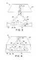
- FIG. 3is a diagrammatic dead sectional view taken along line 3 — 3 of FIG. 1 showing a canopy in a raised position, pivotable side walls pivoted to a down position, and a patient on the patient-support surface, the patient being positioned to lie in the patient space defined between the air curtains and the patient-support surface;
- FIG. 4is a view similar to FIG. 3 showing the patient thermal support device in an enclosed position having the canopy in a down position over the patient-support surface and the pivotable walls in the up position to enclose the patient in the patient thermal support device;
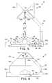
- FIG. 5is a view similar to FIG. 3 of a second embodiment of a patient thermal support device showing a canopy in a raised position, pivotable canopy side members pivoted upwardly, and slidable side walls moved to a down position to maximize the access of the caregiver to the patient;
- FIG. 6is a view similar to FIG. 5 showing the patient thermal support device in an enclosed position having the canopy in a down position over the patient-support surface, the canopy side members pivoted downwardly, and the slidable side walls moved to an up position to enclose the patient;
- FIG. 7is an exploded perspective view of the patient-support portion of the patient thermal support device of FIG. 1 showing a tub formed to include a tank-like mattress well and an air handling assembly formed around the mattress well, a deck over the tub having a plurality of vents around a platform formed on the deck, removable walls surrounding the deck, and a canopy movably coupled to the canopy-support arm connected to the tub;
- FIG. 8is an enlarged exploded perspective view of a foot end of the tub showing elements of the air handling assembly
- FIG. 9is a top plan view with portions broken away of the foot end of the tub showing elements of the air handling assembly
- FIG. 10is a sectional view taken along line 10 — 10 of FIG. 9 showing elements of the air handling assembly
- FIG. 11is an enlarged exploded perspective view of the foot end of the tub showing the air handling unit and the elements of the humidifier;
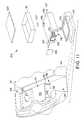
- FIG. 12is an exploded perspective view of the canopy and a portable accessory unit docking with the canopy, the assessory unit including a pivotable coupling having rearwardly projecting mounting pins and a plug for electrically connecting to a socket in the canopy;
- FIG. 13is a view similar to FIG. 12 of a second embodiment of a canopy and a portable accessory unit, the canopy including a pivotable coupling and the accessory unit including pins (not shown) and a plug (not shown) connected to the pivotable coupling, the accessory being pivoted away from the canopy to an out-of-the-way position exposing a radiolucent x-ray window;
- FIG. 14is a perspective view of the tub showing a mattress carried by a mattress positioning assembly mounted in a mattress well of the tub;
- FIG. 15is an exploded perspective view of the mattress and the mattress positioning assembly showing a platform carrying the mattress, load cells mounted to the platform, and extender assemblies mounted beneath the load cells;
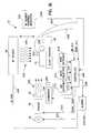
- FIG. 16is a block diagram illustrating a controller for controlling operation of a convective heater and a radiant heater to warm the infant on the sleep surface;
- FIG. 17is a data flow diagram between the controller, a user interface, and the remaining components of the infant thermal support device of the present invention.
- FIG. 18is a control block diagram for an Air Mode of operation of the present invention.
- FIG. 19is a block diagram of a heater control circuit
- FIG. 20is a flow chart illustrating the steps performed by the controller during an Air Mode of operation
- FIG. 21is a control block diagram of the controller of the present invention.
- FIG. 22is a diagrammatic view illustrating control of the convective heater and radiant heater in a Baby Mode of operation
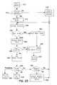
- FIG. 23is a flow chart illustrating the steps performed by the controller during the Baby Mode of operation
- FIG. 24is a flow chart illustrating the steps performed by the controller of the present invention during a Procedure Mode of operation.
- FIG. 25is a block diagram illustrating additional features of the present invention.
- FIG. 1A patient thermal support device 10 in accordance with the present invention is illustratively shown in FIG. 1 .
- Device 10includes a patient-support portion 12 for supporting a patient 14 .
- patient 14is broadly defined to include anyone under the medical supervision of a physician.
- a base portion 16 having castors 18 , brake/steer pedals 20 coupled to castors 18 , and a canopy-support arm 22 supporting a canopy 24is mounted to patient-support portion 12 .
- Canopy-support arm 22can be mounted to a foot end 84 of patient-support portion 12 , at a head end 88 of patient-support portion 12 as shown in FIG. 1, or to the sides of patient-support portion 12 as shown diagrammatically in FIGS. 5 and 6.
- Base portion 16can be provided with drawers (not shown) that slide through base portion 16 for use on both sides of device 10 , the drawers having removable trays (not shown) with adjustable bins (not shown).
- Base portion 16also includes telescoping members 62 , 64 so that the height of base portion 16 and patient-support portion 12 is adjustable. Base portion 16 and patient-support portion 12 cooperate to define a frame.
- the preferred patient thermal support device 10provides heated first and second air curtains 26 , 28 directed upwardly from the sides of patient-support portion 12 as shown diagrammatically in FIGS. 2 and 3 to block the flow of air from outside of device 10 past air curtains 26 , 28 .
- device 10can provide a heated third air curtain 30 along either the head or the foot of patient-support portion 12 , preferably directed underneath air curtains 26 , 28 , and device 10 can be configured to provide a heated fourth air curtain 32 opposing third air curtain 30 as shown in FIG. 2 .
- Patient-support portion 12 of patient thermal support device 10includes a deck 34 carrying a platform 36 shown diagrammatically in FIGS. 3-6 and shown in FIGS. 14 and 15.
- a mattress 38 having an upwardly-facing patient-support surface 40rests on platform 36 and a plurality of air vents 42 surround the perimeter of mattress 38 as shown in FIGS. 2-6.
- Canopy-support arm 22is formed to include an exhaust opening 44 that is vertically spaced-apart from patient-support surface 40 .
- Air curtains 26 , 28extend generally from the perimeter of mattress 38 toward exhaust opening 44 to define a patient space 46 thereunder.
- air curtains 26 , 28have an air velocity between 0.2 and 0.5 meters per second (0.66-1.6 feet per second) coming out of air vents 42 and a temperature of 42 degrees centigrade or less coming out of air vents 42 .
- air curtains 26 , 28are preferably directed at an angle 48 of 45 degrees above patient-support surface 40 as shown, for example, in FIG. 3 forming an air curtain “tent” above patient 14 .
- An effective air curtain tentcan be maintained when angle 48 is lowered as shown in FIG. 5 to any angle that does not result in direct impingement of air curtains 26 , 28 on patient 14 and angle 48 can be raised as high as 90 degrees above patient-support surface 40 without eliminating the effectiveness of air curtains 26 , 28 at blocking the flow of outside air into the tent.
- air curtains 26 , 28are not generally directed at patient 14 .
- air from air curtains 30 , 32is delivered to patient 14 in patient space 46 beneath air curtains 26 , 28 .
- Air curtains 30 , 32are configured so that the velocity of air delivered to patient 14 is no greater than approximately 0.15 meters per second (0.49 feet per second).
- air curtains 26 , 28 , 30 , 32can be configured so that any of the four air curtains 26 , 28 , 30 , 32 is directed upwardly and any other of the four air curtains 26 , 28 , 30 , 32 is directed into patient space 46 .
- the angle formed between each air curtain 26 , 28 , 30 , 32 and patient-support surface 40such as angle 48 shown in FIG. 3, can differ for each air curtain 26 , 28 , 30 , 32 so that all four air curtains 26 , 28 , 30 , 32 are at different angles relative to patient-support surface 40 .
- Heat transfer to and from patient 14can occur primarily through any of the mechanisms of conductive, convective, and radiant heat transfer, as well as through evaporative heat loss that accompanies the evaporation of moisture from patient 14 .
- Conductive heat lossaccounts for a very low portion of the heat loss from patient 14 and radiant heat loss can be minimized by heating surfaces such as platforms and walls surrounding patient 14 .
- Evaporative and convective heat lossescan be controlled by controlling the air in patient space 46 . Factors that operate to influence the extent of evaporative and convective heat losses include the temperature and velocity of the air directed at patient 14 and the moisture content of the air in patient space 46 surrounding patient 14 .
- Directing heated air against an object that is initially at a temperature below that of the heated aircan result in two competing heat transfer effects.
- the heated aircan raise the temperature of the object through convection.
- the heated aircan cause moisture associated with the object to evaporate resulting in evaporative moisture losses and, as a result, evaporative heat losses.
- the warming effect due to convection and the cooling effect due to evaporative heat lossesboth increase, but at different rates.
- air having no supplemental humidity at 38 degrees C. directed against patient 14will substantially warm patient 14 so long as the air is below a velocity of approximately 0.15 meters per second (0.49 feet per second) at patient 14 .
- the evaporative heat lossesstart to work against the convective gains so that at some higher threshold air velocity, the evaporative heat losses withdraw heat from patient 14 at a faster rate than convection supplies heat to patient 14 , so that increasing air velocity above the threshold velocity causes a net withdrawal of heat from patient 14 .
- Air curtains 26 , 28reduce the movement of air from outside of patient space 46 through air curtains 26 , 28 and into patient space 46 . Air curtains 26 , 28 minimize the ingress of air currents from outside of patient space, thereby controlling patient space 46 . Air curtains 26 , 28 thus isolate patient 14 from the air outside of patient space 46 defining a “thermo-neutral” environment and acting as a blanket allowing the warmth generated by patient 14 to maintain the temperature of patient 14 at a desired temperature.
- Patient 14typically has a far higher moisture content than is found in the air of patient space 46 surrounding patient 14 .
- This moisture gradientcan result in significant evaporative moisture losses and evaporative heat losses from patient 14 , designated by arrows 52 in FIGS. 3-6, even when no moving air is directed at patient 14 .
- Air curtains 26 , 28minimize evaporative moisture losses by containing the moisture lost by patient 14 in patient space 46 to minimize the moisture gradient between patient 14 and patient space 46 .
- patient thermal support device 10can be operated in an enclosed mode as shown diagrammatically in FIGS. 4 and 6 having air curtains 26 , 28 , 30 , 32 humidified to increase the moisture content of air curtains 26 , 28 , 30 , 32 .
- Increasing the moisture content of air curtains 26 , 28 , 30 , 32creates a second moisture gradient between air curtains 26 , 28 , 30 , 32 and patient space 46 .
- This second moisture gradientcauses moisture from air curtains 26 , 28 , 30 , 32 designated by arrows 54 in FIGS. 4 and 6 to transfer to patient space 46 . Transferring moisture into patient space 46 further reduces the moisture gradient between patient space 46 and patient 14 , and as a result, further reduces evaporative moisture losses and evaporative heat losses from patient 14 .
- Air curtains 30 , 32can be configured to direct air against patient 14 , as shown in FIG. 2, preferably at a velocity of approximately 0.15 meters per second (0.49 feet per second) or less at patient 14 so that this air warms patient 14 .
- the air in air curtains 26 , 28 , 30 , 32can be heated so that convective heat transfer from air curtains 30 , 32 can augment the warmth generated by patient 14 to warm patient 14 isolated in patient space 46 .
- Patient thermal support device 10can additionally be provided with a radiant warmer 56 as shown in FIG. 1 .
- Radiant warmer 56generates and directs infrared radiation at patient 14 to warm patient 14 .
- heated air in air curtains 26 , 28 , 30 , 32is not at a temperature higher than 42 degrees C. when coming out of air vents 42 .
- radiant warmer 56can be used to provide additional warmth to patient 14 .
- radiant warmer 56is a secondary supplement that augments both the warmth generated by patient 14 and the convective heating provided by heated air from air curtains 30 , 32 to warn patient 14 to a desired temperature.
- Deck 34 of patient thermal support device 10can be configured as shown in FIG. 2 having a convective return 60 extending upwardly from deck 34 to exhaust opening 44 , a side wall 146 cooperating with convective return 60 to define an inner deck 158 , and a warmed storage area 164 on inner deck 158 adjacent to patient-support surface 40 for the storage of items (not shown) that may be used on patient 14 .
- itemsfor example, alcohol wipes, probes, and saline bottles could all be stored in the warmed storage area. Because warmed storage area is under canopy 24 , items stored will remain relatively warm and at a temperature close to the temperature of the air surrounding patient 14 . Keeping such items at or near the temperature of the air surrounding patient 14 reduces the “cold shock” experienced by patient 14 upon initial contact of the items with the skin of patient 14 .
- Patient-support portion 12can also be provided with a rotating display 160 as shown in FIGS. 1 and 2.
- Display 160is located generally at the waist level of an adult caregiver although the vertical position of display 160 is adjustable with changes in height of base portion 16 .
- rotating display 160is pivotably mounted to canopy-support arm 22 to pivot from side to side of device 10 , and is positioned to lie outside of inner deck 158 .
- Patient-support portion 12includes a tub 70 having a mattress well 72 surrounded by an air curtain generator or air handling assembly 74 as shown in FIGS. 7 - 11 and 13 .
- Deck 34is carried on tub 70 and canopy-support arm 22 is supported by both deck 34 and tub 70 .
- Air handling assembly 74includes a heater 76 , a fan 78 , a fan motor 79 , a filter 80 , a divider 82 , and various channels or pathways formed in tub 70 as shown in FIGS. 7-11.
- Tub 70includes a foot end 84 having a wall 86 , a head end 88 having a wall 90 , and two elongated sides 92 , 94 therebetween as shown in FIG. 7.
- a transverse bulkhead 96extends between the sides 92 , 94 and is spaced-apart from walls 86 , 90 to define a space containing an air make-up compartment 98 and an air mixing space 126 between bulkhead 96 and wall 86 .
- Tub 70further includes an inner wall 112 defining mattress well 72 as shown in FIG. 7 .
- Inner wall 112cooperates with bulkhead 96 and sides 92 , 94 to define a manifold or air delivery channel 110 in fluid communication with an opening 116 formed in bulkhead 96 as shown in FIGS. 8 and 9.
- Deck 34is formed to include openings or vents 42 in fluid communication with air delivery channel 110 .
- Air delivery channel 110receives air from air make-up compartment 98 through opening 116 in bulkhead 96 and delivers the air to vents 42 . Vents 42 direct the air from channel 96 to form air curtains 26 , 28 , 30 , 32 .
- tub 70can be formed so that air delivery channel 96 additionally extends adjacent to wall 90 on head end 88 between wall 90 and inner wall 112 so that channel 96 surrounds mattress well 72 to deliver air from air make-up compartment 98 to air curtains 26 , 28 , 30 , 32 .
- air delivery channel 110 and vents 42can be configured so that not all air curtains 26 , 28 , 30 , 32 are available.
- channel 110 and vents 42can cooperate so that only air curtains 26 , 28 along sides 170 , 172 of platform 36 are present by forming vents 42 only along sides 170 , 172 of platform 36 .
- Another potential configurationcould have air delivery channel 110 and vents 42 configured so that only air curtains 30 , 32 along ends 174 , 176 of platform 36 are present, for example, by forming vents 42 only along ends 174 , 176 of platform 36 .
- air curtainsare present, including air curtains 26 , 28 along sides 170 , 172 of platform 36 directing air above patient 14 and air curtains 30 , 32 along the ends 174 , 176 of platform 36 delivering warm air to patient 14 .
- the top of inner wall 112 of patient-support portion 12can be spaced-apart from the bottom of platform 36 to form a bleeder hole (not shown) therebetween.
- the bleeder holecan be configured to allow a small amount of heated air from air delivery channel 110 to bleed into mattress well 72 . This heated air can heat the bottom surface of platform 36 consequently heating patient-support surface 40 by conduction through platform 36 and mattress 38 .
- bleeder holecan also be an opening formed in wall 112 .
- Bleeder holecan be any opening, channel, or conduit through which heated air enters mattress well 72 beneath platform 36 .
- Air make-up compartment 98holds the heater 76 , fan 78 , filter 80 , and divider 82 as shown best in FIGS. 7-10.
- Air make-up compartment 98includes first and second walls 118 , 120 defining a fan compartment 122 and cooperating with bulkhead 96 to define an air make-up channel 124 .
- First and second walls 118 , 120are shorter than wall 86 , sides 92 , 94 , and bulkhead 96 .
- Divider 82rests on top of walls 118 , 120 .
- the bottom of divider 82defines a top of air make-up channel 124 and the top of divider 82 cooperates with wall 86 , sides 92 , 94 , and bulkhead 96 to define an air-mixing space 126 .
- Wall 86 along foot end 84 of tub 70is formed to include a fresh air inlet 128 in fluid communication with air-mixing space 126 as shown in FIG. 8 .
- exhaust opening 44 formed in canopy-support arm 22 and positioned to lie above patient-support surface 40 to receive air from air curtains 26 , 28 , 30 , 32is in fluid communication with a convective return opening 130 through convective return 60 and is in fluid communication with air-mixing space 126 as shown in FIGS. 7-10.
- air from air curtains 26 , 28 , 30 , 32travels through exhaust opening 44 , through convective return 60 , and through convective return opening 130 to mix with fresh air from fresh air inlet 128 in air-mixing space 126 above divider 82 .
- Fan 78is rotatably received in fan compartment 122 and fan motor 79 is positioned to lie in tub 70 beneath fan 78 as shown in FIG. 10 .
- Fan 78pressurizes the air in fan compartment 122 and forces the pressurized air into air make-up channel 124 .
- Bulkhead 96is formed to include an opening 116 in fluid communication with air make-up channel 124 and air delivery channel 110 .
- the pressurized air in air make-up channel 124travels through opening 116 in bulkhead 96 into air delivery channel 110 , and then through vents 42 to form air curtains 26 , 28 , 30 , 32 .
- Fan 78additionally pulls return air from air curtains 26 , 28 , 30 , 32 along with air from outside of patient space 46 into exhaust opening 44 as shown in FIG. 2 . The return air then travels through convective return 60 and convective return opening 130 to air-mixing space 126 as shown in FIGS. 8-10. In addition to drawing return air into air-mixing space 126 , fan 78 draws fresh air into air-mixing space 126 through fresh air inlet 128 as shown in FIG. 8 .
- Fresh air inlet 128can be provided with a damper (not shown) to adjust the effective size of fresh air inlet 128 and thus adjust the ratio of fresh air to return air that is drawn into air-mixing space 126 and subsequently circulated into air curtains 26 , 28 , 30 , 32 . Satisfactory results have been achieved when the air in air-mixing space 126 includes approximately 80% return air from convective return 60 and 20% fresh air from fresh air inlet 128 .
- patient support portion 12includes sensors (not shown) for detecting when one or more of vents 42 are blocked.
- the velocity of air at a vent 42could be detected by two spaced-apart elements (not shown) that are typically biased at different power levels so that the elements are at different temperatures.
- the power to the elementscan be removed while air flows across the elements and the temperature difference between the elements can be measured. Variations of the temperature difference between the two elements could signify that air flow by one element is disrupted by, for example, a toy or blanket blocking vent 42 .
- the patient thermal support device 10can be configured to alert the caregiver to this potential problem.
- Air make-up compartment 98additionally includes heater 76 positioned to lie between first and second walls 118 , 120 in air make-up channel 124 as shown in FIGS. 7-10. As air from fan 78 passes between fins 132 of heater 76 , the air is warmed. The temperature of the air after passing over heater 76 can be varied by varying the temperature of heater fins 132 .
- Air make-up compartment 98can also be provided with a humidifier 134 for adding moisture to the air in air make-up channel 124 as shown in FIGS. 9-11.
- Humidifier 134is positioned to lie in air make-up channel 124 along the air flow path past heater 76 as shown in FIGS. 9 and 10.
- humidifier 134is a module that can be easily installed and removed from air make-up compartment 98 through opening 136 formed in tub 70 as shown in FIG. 11 .
- Air handling assembly 74can be provided with swinging doors 138 that are spring loaded and yieldably biased to a closed position as shown in FIG. 11 . When doors 138 are in the closed position, doors 138 define an end of air make-up channel 124 .
- Illustrative humidifier 134includes an evaporator tray 143 having a heater (not shown), the heater and tray 143 being carried by a base 145 as shown in FIG. 11 .
- Tray 143cooperates with cabinet 147 having a top 149 and a wall 151 about the perimeter of top 149 to define chamber 141 .
- Wall 151is formed to include an entrance 153 and an exit 155 .
- a door 157is pivotably coupled to wall 151 adjacent entrance 153 to cover entrance 153 and a door 159 is coupled to wall 151 adjacent exit 155 to cover exit 155 .
- Humidifier 134also includes a reservoir 161 and a reservoir lid 163 illustratively positioned above cabinet 147 for containing a water supply for humidifier 134 as shown in FIG. 11 .
- Top 149 of cabinet 147is formed to include an opening 165 and reservoir 161 includes a companion opening (not shown) in fluid communication with opening 165 through a flow regulator 167 .
- illustrative reservoir 161is a tank positioned above cabinet 147 inside of air make-up compartment 98
- reservoir 161can be any source of water in fluid communication with tray 143 and can be positioned to lie inside or outside of tub 70 .
- reservoir 161could be a bag (not shown) filled with water and hanging from side 94 of tub 70 .
- Evaporator tray 143is heated to vaporize water on tray 143 and to form water vapor over tray 143 .
- the pressurized air in air make-up channel 124passes through entrance 153 and into chamber 141 .
- the pressurized airthen carries the water vapor from over tray 143 , through exit 155 , into air-make-up channel 124 , through opening 116 in bulkhead 96 , to air delivery channel 110 and into air curtains 26 , 28 , 30 , 32 .
- humidifier 134into air make-up compartment 98
- air delivery channel 110is effectively expanded to include chamber 141 and the air in air curtains 26 , 28 , 30 , 32 is humidified to increase the moisture content of air curtains 26 , 28 , 30 , 32 .
- patient thermal support device 10can be operated in an enclosed mode minimizing the air from outside of patient space 46 drawn into exhaust opening 44 and maximizing the amount of recirculated air in air curtains 26 , 28 , 30 , 32 .
- the proportion of recirculated air pulled by fan 78 into air make-up compartment 98 from air-mixing space 126increases, the moisture content of the air in air curtains 26 , 28 , 30 , 32 increases.
- canopy-support arm 22includes telescoping members so that canopy 24 is vertically movable relative to patient-support surface 40 between the raised position shown in FIGS. 1, 3 , and 5 and the enclosed position shown in FIGS. 4 and 6. Exhaust opening 44 is movable with canopy 22 .
- Canopy-support arm 22encloses a sensor 234 that detects the vertical position of canopy 24 relative to patient-support surface 40 .
- air curtains 26 , 28 , 30 , 32originate at air vents 42 along the perimeter of patient-support surface 40 and the air from air curtains 26 , 28 , 30 , 32 is drawn away through exhaust opening 44 .
- exhaust opening 44moves relative to patient-support surface 40 and air vents 42 , the rotational speed of fan 78 can be varied, thereby varying the velocity of air comprising the air curtains as well as varying the suction at exhaust opening 44 which pulls the air comprising air curtains 26 , 28 , 30 , 32 through exhaust opening 44 .
- rotational speed of fan 78can be increased to increase the velocity of the air comprising air curtains 26 , 28 , 30 , 32 and to increase the suction at exhaust opening 44 .
- This increased rotational speed of fan 78thus assures the integrity of air curtains 26 , 28 , 30 , 32 even when exhaust opening 44 is moved away from patient-support surface 40 .
- Patient thermal support device 10 in accordance with the present inventioncan also be provided with side wall 146 including side wall portions 148 , 150 , 152 , 154 , 156 as shown in FIGS. 1-6 to provide additional protection for patient 14 .
- Side wall portions 148 , 150 , 152 , 154 , 156are pivotable between an upward enclosed position as shown diagrammatically in FIG. 4 for side walls 150 , 154 , and a down-out-of-the-way position shown diagrammatically in FIG. 3 maximizing the access of the caregiver to patient 14 .
- canopy 24can include two elongated spaced-apart canopy side members 140 , 142 and an elongated support 144 sandwiched therebetween as shown in FIGS. 1, 5 , and 6 .
- Support 144is connected to the canopy-support arm 22 and each canopy side member 140 , 142 is pivotably connected to support 144 for pivoting movement relative to support 144 between a down position generally parallel to the patient-support surface shown in FIG. 6 and an up position maximizing access to the patient space 46 as shown in FIG. 5 .
- patient thermal support device 10can be moved between the enclosed position of FIGS. 4 and 6 having side wall portions 148 , 150 , 152 , 154 , 156 moved to the up position and canopy 24 in the lowered position to fully enclose patient 14 and the position of FIGS. 3 and 5 having side wall portions 148 , 150 , 152 , 154 , 156 in the down-out-of-the-way position and canopy 24 in the raised position to maximize the caregiver's access to patient 14 .
- canopy side members 140 , 142can be pivoted upwardly to provide the caregiver with even greater access to patient 14 as shown in FIG. 5 .
- the return airis comprised almost entirely of air from the air curtains.
- the same airwill make several passes over humidifier 134 .
- the moisture added to the recirculating air in air curtains 26 , 28 , 30 , 32can be increased, maximizing the moisture gradient between the air in air curtains 26 , 28 , 30 , 32 and patient space 46 .
- the maximized moisture gradient between air curtains 26 , 28 , 30 , 32 and patient space 46will maximize the moisture transfer from air curtains 26 , 28 , 30 , 32 to patient space 46 and minimize the moisture gradient between patient 14 and patient space 46 , thus minimizing the evaporative heat losses of patient 14 .
- Canopy 24can also be provided with a radiolucent x-ray window 178 positioned to lie above patient-support surface 40 , as shown in FIGS. 7, 12 , and 13 , for use during fluoroscopic procedures.
- X-ray window 178is configured to carry an x-ray generator (not shown).
- Mattress 38can be raised above vents 42 by a mattress positioning assembly 180 to receive an x-ray cassette holder or tray 193 as shown in FIGS. 14 and 15.
- Mattress 38is typically lowered back beneath vents 42 during use after tray 193 is received by mattress positioning assembly 180 .
- Use of x-ray window 178allows for the completion of fluoroscopic procedures on patient 14 without removing patient from patient space 46 .
- Canopy 24can additionally be provided with a canopy-mounted accessory 162 mounted to support 144 as shown in FIGS. 12 and 13.
- Accessory 162can be, for example, an optical radiation source accessory that directs visible light toward patient 14 for photo therapy treatment of conditions such as jaundice.
- Accessory 162can include a pivotable connector 192 for connecting to canopy 24 as shown in FIG. 12 or canopy 24 can include a pivotable connector 194 for connecting to accessory 162 as shown in FIG. 13 .
- Pins 195 mounted to canopyare received by openings 197 on support 144 , shown best in FIG. 7, and a plug 196 , shown in FIG. 12, electrically connects accessory 162 to infant thermal support device 10 .
- Accessory 162mounts above x-ray window 178 and above exhaust opening 44 and connectors 192 , 194 receive plug 196 of accessory 162 .
- Accessory 162thus docks to canopy 24 , rests on x-ray window 178 , and is controlled by controller 200 as shown in FIG. 16 .
- Accessory 162is rotatable about a pivot axis 198 adjacent to plug 196 as shown in FIGS. 12 and 13 to allow access to x-ray window 178 as shown in FIG. 13 during fluoroscopic procedures. Additionally, accessory 162 can be easily removed and re-installed so that one accessory 162 can be moved between several patient thermal support devices 10 .
- Patient thermal support device 10can also be provided with a mattress positioning assembly 180 as shown in FIGS. 14 and 15.
- patient thermal support device 10is provided with weighing capability.
- Scale load cells 182are mounted beneath platform 36 and between platform 36 and mattress positioning assembly 180 . Load cells 182 provide signals indicating the weight of platform 36 and objects carried by platform 36 , including mattress 38 and patient 14 , to an output device such as display 160 .
- Mattress positioning assembly 180includes scissors-type extenders 184 having a top end coupled to load cells 182 as shown best in FIG. 15 .
- Lead screws 186are coupled to the bottom ends of extenders 184 .
- Lead screws 186can be rotated to extend and retract extenders 184 thereby raising and lowering the ends of platform 36 coupled to extenders 184 through load cells 182 .
- Lead screws 186extend through openings (not shown) in tub 70 and knobs 188 are fixed to lead screws 186 as shown in FIG. 14 to allow the caregiver to rotate lead screws 186 manually.
- Platform 36 and consequently patient-support surface 40 of mattress 38can be adjusted to a Trendelenburg position having patient-support surface 40 tilted at approximately 10 degrees with the head end of patient-support surface 40 lower than the foot end of patient-support surface 40 .
- Patient-support surface 40can also be moved to a reverse Trendelenburg position having patient-support surface 40 tilted at approximately 10 degrees with the foot end of patient-support surface 40 lower than the head end of patient-support surface 40 .
- platform 36can be raised and lowered between an upward position having patient-support surface 40 above vents 42 to facilitate procedures such as intubation of patient 14 and downwardly beneath vents 42 so that if overlays (not shown) are placed on top of mattress 38 resulting in a greater effective mattress thickness, mattress 38 and the overlays can be moved so that the sleeping surface on top of both mattress 38 and the overlays is at the desired height relative to vents 42 .
- Platform 36can additionally be formed to include a slot 190 for receiving tray 193 beneath platform 36 as shown in FIGS. 14 and 15.
- Tray 193can be used, for example, to carry equipment such as an x-ray cassette 197 for fluoroscopic procedures.
- accessory 162is rotatable about pivot axis 198 to expose x-ray window 178 during fluoroscopic procedures.
- Mattress 38 and platform 36are made from radiolucent materials so that x-ray generating equipment (not shown) can be placed above x-ray window 178 and x-ray cassette 197 holding film can be placed in tray 193 allowing fluoroscopic procedures to be performed on patient 14 while patient 14 remains on patient-support surface 40 .
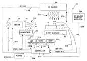
- FIG. 16illustrates a control system for the infant thermal support device 10 .
- FIG. 16illustrates the infant support portion or sleep surface 38 , a convection heater 76 , a radiant heater 56 , a humidifier 134 , and a controller 200 .
- the sleep surface 38is designed to support an infant or baby 14 in such a position so that either the convection heater 76 or the radiant heater 56 can heat the baby 14 as discussed above.
- the baby 14can also be warmed by a combination of the convection heater 76 and radiant heater 56 .
- the convection heater 76 and the radiant heater 56can be used to warm the baby 14 either directly or indirectly.
- the terms “baby” and “infant”are used in this specification, is understood that any patient can use the present apparatus of the present invention, not just a baby or infant.
- Controller 200is a microprocessor based controller having an internal memory.
- the controller 200receives various inputs.
- a baby temperature probe or sensor 202is attached to the baby 14 to provide a measured baby temperature output signal to the controller 200 on line 204 .
- an air temperature probe or sensor 206is positioned near the baby 14 to provide a measured air temperature output signal.
- the air temperature sensor 206is connected to the controller 200 by line 208 .
- An air temperature set point input device 210is coupled to controller 200 by line 212 .
- the air temperature input deviceallows a caregiver to set a desired air temperature setpoint.
- a mode selector 214is also coupled to controller 200 by line 216 . Mode selector 214 permits a caregiver to select between a Baby Mode of operation, an Air Mode of operation, and a Procedure Mode of operation for the device 10 as discussed in detail below.
- a baby temperature set point input device 218is coupled to controller 200 by line 220 .
- the baby temperature input device 218permits a caregiver to select the desired temperature for the baby 14 .
- Controller 200controls heater 76 and fan 78 to supply a correct amount of convective heat to the infant thermal support device 10 to warm the baby 14 as illustrated diagrammatically by arrows 226 .
- Air flowis controlled by a plurality of vents 42 . Vents 42 direct air to warm the baby 14 and also direct air to form one or more air curtains to provide a controlled patient space.
- controller 200controls the IR output from radiant heater 56 .
- the position of radiant heater 56is adjustable in the direction of double-headed arrow 230 relative to sleep surface 38 by adjusting the canopy support arm (not shown).
- Heater 56emits infrared radiation as illustrated diagrammatically by arrows 232 to warm the baby 14 .
- the intensity of radiant heater 56is adjusted by controller 200 depending upon the position of the heater 56 relative to the sleep surface.
- a potentiometer or other position indicator 234is provided to generate an output signal indicative of the position of the radiant heater 56 relative to sleep surface 38 .
- An output of position indicator 234is coupled to controller 200 by line 236 . Controller 200 therefore adjusts the output of radiant heater 56 based on the output signal from position indicator 234 on line 236 .
- An output from controller 200 on line 238is coupled to an audible alarm 240 and/or an alarm light 242 .
- Alarms 240 and 242are used to alert a caregiver of various situations as discussed below.
- An output from controller 200also controls or adjusts the humidifier 134 to control the amount of moisture in the air supplied by the convective heater and used to generate the air curtains.
- a humidity sensor 388provides an output signal indicative of the detected relative humidity in the air adjacent sleep surface 38 .
- the controller 200uses the output signal from humidity sensor 388 to control humidifier 134 to maintain the relative humidity at substantially a preselected level.
- an input deviceis used to permit the caregiver to adjust the preselected humidity level.
- FIG. 17illustrates a data flow block diagram for the controller 200 of the present invention.
- a sensor 244is provided to indicate that the temperature sensor 202 has come loose from baby 14 .
- a loose probe signal from sensor 244causes controller 200 to generate an alarm signal on alarms 240 and 242 .
- vent blocked sensors 246are coupled to controller 200 .
- Sensors 246illustratively include a right vent blocked sensor, a left vent blocked sensor, a front vent blocked sensor, and a rear vent blocked sensor.
- An air inlet blocked sensor 250is also coupled to controller 200 . Sensors 246 and 250 provide signals to controller 200 to generate alarms 240 and 242 if the air vents or the air inlet are blocked.
- Right vent blocked sensor 246 and left vent blocked sensor 248detect when air vents adjacent sleep surface 38 are blocked. Sensors 246 and 248 provide an input to controller 200 which generates an output signal on display 255 of user interface of 160 or on alarms 240 or 242 .
- a pair of sensorsare co-located on a narrow material with a low thermal conductivity.
- sensors 246 and 248may be a pair of silicon temperature sensors placed on a thin Kapton ribbon. One of the sensors is operated at a low power level. The other is operated at a moderately high power level, resulting in self-heating of the semi-conductor die and thus an increased temperature indication from the sensor. Air flowing through the vents and across the sensor removes heat and therefore lowers the effective temperature indication.
- the airflow rateis inversely proportional to the difference of the readings from the two sensors. Therefore, when the temperature difference rises above a predetermined level, an output signal is generated by controller 200 to initiate alarm 240 or alarm 242 or to provide an indication on display 255 .
- An AC current sensor 252is also coupled to controller 200 .
- an AC zero crossing sensor 254is coupled to controller 200 . Sensors 252 and 254 permit controller 200 to monitor current before and after the device 10 is turned on. During an “off” period, controller 200 detects whether the heaters actually turn off. The zero crossing sensor 254 checks operation of current sensor 252 and resets the system if no signal is present.
- a fan tachometer 256is coupled to controller 200 . Fan tachometer 256 provides an input signal to controller 200 indicative of the fan speed. Controller 200 compares the actual fan speed from fan tachometer 256 to the desired fan speed and adjusts a fan command signal to fan 78 accordingly.
- a user interface 160permits the caregiver to input information into controller 200 .
- the user interface 160may be separate input devices such as devices 210 , 214 , and 218 .
- the user interface 160permits the caregiver to input information to controller 200 related to the operation mode, the air temperature set point, the baby temperature set point, a real time clock, and an alarm silencer.
- a rotatable control wheel 257is used to scroll through various menu control options. It is understood that any type of control input device may be used.
- Controller 200outputs information related to an alarm code, air temperature, and baby temperature to the user interface 160 .
- User interface 160includes a display 255 so that control information can be displayed to the caregiver.
- controller 200The communication between controller 200 and user interface 160 is implemented by a serial interface using a master-slave protocol.
- the controller 200is the master, and the user interface 160 is slave.
- Controller 200controls a communication link by initiating the message transfer.
- the controller 200generates a start condition, the user interface address, the read/write bit indicating whether the message is a transmission to the user interface 160 (write) or a request for a message from the user interface 160 (read).
- Controller 200also generates a stop condition which indicates the end of a message.
- the user interface 160responds only when a transfer has been initiated by the master controller 200 . It is understood that other communication protocols may be used in accordance with the present invention.
- the controller 200 of the present inventionhas three operating modes for controlling warming of the baby 14 . These operation modes are a Baby Mode, an Air Mode and a Procedure Mode. In the Air Mode, chamber air is under servo-control. The control point is the air setpoint. The infrared energy source is disabled during Air Mode. In the Baby Mode, the controller 200 combines convective heat and infrared energy to servo-control about the baby temperature setpoint. In the Procedure Mode, infrared energy is supplied at a level set by the caregiver. Chamber air is warmed to a preset level using the convective heater.
- air setpointis a control point temperature for Air Mode.
- the “baby setpoint”is a control point temperature for Baby Mode.
- Measured air temperatureis a calibrated temperature measurement of the ambient air by sensor 206 in the vicinity of the sleep surface 38 .
- “Measured baby temperature”is a calibrated temperature measurement of the probe 202 on the baby.
- “Overhead arm condition”is an indication of the relative position of the overhead arm supporting radiant heater 56 from position indicator 234 .
- Convective commandis a value that represents the percent convective heater power.
- IR commandis a value that represents the desired power density at the mattress surface.
- Stabilityor “stable” is when temperature fluctuations of less than 0.3° C. are observed, and these fluctuations are predominately centered about the setpoint.
- the deviceWhen power to the device 10 is turned on, two possible states are defined, distinguished by the amount of time that the device 10 has been shut off. A warm-start is initiated if the device has been off for less than 10 minutes. The operating mode, setpoints and other conditions in effect prior to the power loss are restored. Controller 200 then resumes control functions, in the state that it was just prior to the removal of power.
- the devicealso includes a Prewarm Mode (Cold-Start).
- the Prewarm Modeis initiated by controller 200 automatically if the power on occurs more than 10 minutes from the last use of the device. This prewarm mode is intended to assist caregivers in preparing the device for use.
- the functionality of the prewarm “mode”is that of air-mode with the air setpoint at a default value (e.g. 35° C.).
- An air mode iconwill be illuminated on the display, baby mode and procedure mode icons will be extinguished.
- the message “prewarm”will be indicated on the LCD display screen. Under temperature alarms are inactive in Prewarm mode. Alarms related to system errors (e.g. system failure, heater fault, etc.) are active.
- the message “Ready for Use—Select Operating Mode”appears on the LCD screen. This message stays on the LCD screen until the mode is canceled.
- the Prewarm modeis canceled by deliberate action from the caregiver. This can come at any time during the Prewarm mode. Pressing the mode, increment or decrement keys, will initiate an exit from Prewarm mode.
- Air Modethe air temperature inside the infant receiving space is controlled using only the convective heater 76 and fan 78 .
- the controller 200adjusts the convective heater 76 to maintain the desired air temperature.
- the radiant heater 56is off.
- the baby probe 202is not needed for operation in the Air Mode. If, however, the probe 202 is connected to the device, then the measured baby temperature is displayed.
- the baby temperature setpointis not used in Air Mode.
- An air iconis illuminated, and Baby Mode and Procedure Mode icons are extinguished. Alarms related to system errors (e.g. system failure, heater fault, etc.) are active.
- An “overtemperature condition”exists when the air temperature measured by sensor 206 exceeds the air setpoint by more than 1° C. Overtemperature alarms are always active.
- An “undertemperature condition”exists when the air temperature measured by sensor 206 is less than the air setpoint by more than 1° C. Undertemperature alarms are active after an undertemperature hold-off period. When the air setpoint is increased, the undertemperature alarm is defeated until the air temperature has risen and stabilized about the new setpoint. After the air temperature has been stable for two minutes at the new setpoint, then undertemperature alarm is reactivated.
- a setpoint error (E sp )is continuously calculated by the controller 200 from the difference of the air setpoint (SP air ) and the air temperature measured value as follows:
- SP airis air temperature setpoint.
- MV airis the measured value of the air temperature by sensor 206 .
- Controller 200operates to drive E sp to zero. This is accomplished with “three term” control, providing Proportional (P), Integral (I) and Derivative (D) responses, calculated from the present and recent values of E sp . The individual responses are summed, forming the input to a power output block (the term block is used here to represent a function or group of functions). The power block receives the PID sum and produces an output command which represents the required amount of heater power to drive E sp toward zero.
- PProportional
- IIntegral
- DDerivative
- FIG. 18A block diagram of Air Mode control is illustrated in FIG. 18 .
- the E sp block 260calculates E sp as discussed above.
- the P Block 262 in FIG. 18produces the proportional term which increases with the magnitude of E sp , has the same algebraic sign as E sp , and is zero when E sp is zero. Calculation of the P term is as follows:
- K pis a proportional gain constant.
- the I Block 264 in FIG. 18produces the integral term which is created from calculation of the area of the curve of E sp vs. time. With constant error, I ramps. When the error is zero, I remains unchanged.
- An appropriate numerical methodfor example the trapezoidal rule
- the I termis calculated as follows:
- K iis an integral gain term
- the D Block 266 of FIG. 18produces the derivative term which is created from calculation of the rate of change E sp . With constant error, D is zero.
- K dis a derivative gain term.
- P, I and Dare added together and presented to the power block 268 .
- the power blocktranslates this sum into a heater command to control convective heater 76 .
- the P, I & D termsPrior to summation the P, I & D terms are bounded to assure that the heater response is constrained to reasonable values.
- P maxis the Lower/Upper limit for P.
- I maxis the Lower/Upper limit for I.
- D maxis the Lower/Upper limit for D.
- K htris a heater gain constant
- a functionthe heater power driver, provides power to the heater 76 .
- the input to this functionis H cmd , which is periodically updated by the PID action.
- a block diagram of the heater circuitis illustrated in FIG. 19 .
- the heater load 76is driven from an AC line 270 , and is modulated with a time proportioning algorithm. At any given time, the heater 76 is either on or off. Variable power levels are achieved by modulating the on/off characteristic of heater 76 .
- the minimum on timeis one-half of the AC line period (e.g. 8.3/10.0 ms with 60/50 Hz mains).
- the integration periodis 100 such half-line cycles.
- the integration periodis chosen so that the time constant of the heater is much greater than integration period.
- H cmd40% power, for example, is achieved by turning the heater full on for 40 half-cycles and off for 60 half-cycles.
- a new H cmdis received and a new on/off characteristic is created for the new value of H cmd .
- H cmd signalsare created in the PID function block 262 , 264 , 266 and made available to the heater power driver 272 . These two functions operate asynchronously.
- H cmdis transferred via a mailbox.
- An AC line interface 273is coupled between heater power driver 272 and heater 76 .
- An example outputis:
- Power limitingmay be desired to keep from exceeding the maximum power draw.
- a current sensor 274 on the AC linesare available for this.
- FIG. 20illustrates the steps performed by the controller 200 during the Air Mode of operation.
- the Air Modeis initiated as illustrated as block 276 .
- Controller 200determines whether to use the default temperature setpoint at block 278 . If the default is to be used, the air temperature setpoint is set at 35° C. as illustrated at block 280 . If the default setpoint is not to be used at block 278 , controller 200 restores the previous setpoint established by air temperature setpoint input device 210 . This step is illustrated at block 282 . Once the previous setpoint is restored at block 282 , controller advances to block 284 and samples sensors 202 and 206 . Controller 200 determines whether the skin probe 202 is connected at block 286 . If so, controller 200 display the baby temperature on the display as illustrated at block 288 . If the baby temperature sensor 202 is not connected, controller 200 blanks the baby temperature display as illustrated at block 290 .
- Controller 200next determines whether an alarm condition exists as illustrated at block 292 . If so, the controller 200 sets the alarm code at block 294 and sounds the appropriate alarm 240 or 242 as illustrated at block 296 . If an alarm condition does not exist at block 292 , the controller 200 uses the PID control discussed above to control the air temperature of the device as illustrated at block 298 . Controller 200 then determines whether a mode change has been made on mode selector input 214 at block 300 . If a mode change has occurred, controller 200 moves to either the Baby Mode as illustrated at block 302 or the Procedure Mode as illustrated at block 304 .
- controller 200determines whether the air temperature setpoint has been changed at block 206 . If not, the controller advances back to block 284 . If the air temperature setpoint has been changed at block 306 , controller 200 updates the setpoint temperature and initiates the delay for the under temperature alarm as discussed above as illustrated at block 308 . Controller 200 then advances back to block 284 .
- controller 200makes the full use of both heater systems, applying convective heat from heater 76 and also applying radiant warming from heater 56 as needed to maintain the skin temperature of the baby 14 at the baby temperature setpoint.
- Baby Moderequires that the skin probe 202 is connected to the baby 14 .
- the air temperatureis displayed, but the air temperature setpoint is not used.
- a baby iconis illuminated on the display, and the Air and Procedure mode icons are extinguished.
- An overtemperature conditionexists when the baby temperature exceeds the baby temperature setpoint by more than 0.5° C.
- Overtemperature alarmsare always active.
- An undertemperature alarmexists when the air temperature is less than the baby temperature setpoint by more than 0.5° C. Undertemperature alarms are active after the undertemperature hold-off period. See the discussion in the preceding section (Air Mode) for a definition of undertemperature hold-off.
- the setpoint error (E sp ) for Baby Modeis continuously calculated from the difference of the baby setpoint (SP baby ) and the baby temperature measured value as follows:
- SP babyis the Baby temperature setpoint.
- MV babyis the measured value of the baby.
- the convective heateris controlled with the PID control block, as illustrated in FIG. 21 .
- An additional loop, controlling the IR heateris added when operating in the Baby Mode.
- IR heatingis basically an “I” only controller.
- the IR heating loopderives input from the derivative and heat command (H cmd terms of the convective PID loop.
- K 1is a convective proportional gain constant.
- K 2is a convective derivative gain constant.
- K 3is a convective integral gain constant.
- K 4is an IR proportional gain constant.
- K 5is an IR derivative gain constant.
- the control block diagramis used to generate both the convective heat command for controlling heater 76 and the IR heat command for controlling the radiant heater 56 . Both the heat commands are generated by a pulse width modulation power module.
- the output of the Threshold Comparatoris E sp when H cmd is greater than H ul .
- the output of Threshold Comparatoris zero when H cmd is between H ul and H ll .
- the output of Threshold Comparatoris ⁇ E sp when H cmd is less than H ll .
- the derivative term of the convective loopis responsive to the instantaneous rate of change of E sp . This provides quick IR heating if the baby measured value (MV baby ) drops.
- the H cmd term of the convective looprepresents power applied to the convective heater. When convective power exceeds an upper threshold (H ul ), IR energy begins to ramp up. This continues while the convective power is above H ul . When the convective power falls below a lower threshold (H ll ), the IR energy begins to ramp down. This is illustrated in FIG. 22 .
- I ⁇ ⁇ R e ⁇ ⁇ d ⁇ ( k )IR ed ⁇ ( k - 1 ) + ( K ird ⁇ ⁇ E sp ⁇ t + SGN ⁇ K irp ) ⁇ U ⁇ ⁇ R
- IR ed(k) and IR ed(k ⁇ 1)are IR energy densities (e.g. mW/cm 2 ).
- K irdis an IR gain constant for the derivative term.
- K irpis an IR gain constant for the proportional term.
- URis an update rate of IR ed .
- SGNis +1 when H cmd >H ul , ⁇ 1 when H cmd ⁇ H ll , and 0 otherwise.
- a position indicator 234such as a potentiometer is connected to the arm lift mechanism provides position output signal to controller 200 .
- the potentiometer voltageis periodically monitored by the controller 200 and used in the heater control function.
- the potentiometer voltageranges from V posl to V posh , and varies directly with position.
- V posis the Position Sensor 234 A/D value.
- V psolis a Lower limit on the position A/D value.
- V poshis an Upper limit on the position A/D value.
- OHA relis the Overhead arm relative position.
- the absolute position of the IR sources with respect to the mattress surfaceis:
- 0HA relis the Relative position of the Overhead Arm.
- OHA minis the Position of the Overhead Arm when “full down”.
- IR edis the Energy Density at the mattress surface.
- K iris a constant.
- OHA absis the absolute position of the IR sources wrt to the mattress surface as given in the above equation.
- nis a constant.
- IR cmdis the duty cycle of the IR heater 56 .
- This constant energy density equationcan be re-arranged to yield the IR source duty cycle as a function of Energy Density.
- Modifiers to the control algorithmare necessary to accommodate special conditions.
- the power command to the heatermust be modifiable based on the state of various alarms and system failures. For example if a system failure were to occur, the heater should be commanded to zero power. Power limiting may be necessary to keep from exceeding the maximum power draw. Current sensors on the AC lines are available for this.
- Controller 200determines whether the use the default baby temperature setpoint as illustrated at block 312 . If the default baby temperature setpoint is to be used, controller 200 sets the baby temperature setpoint at 36.5° C. as illustrated at block 314 . If the default setpoint is not used, the controller 200 restores the previous baby temperature setpoint input on the baby temperature setpoint input device 218 as illustrated at block 316 . The controller 200 then advances to block 318 and samples the output signals from sensors 202 and 206 . Controller 200 determines whether skin probe sensor 202 is working or attached at block 320 . If not, controller 200 blanks the baby temperature output on the display as illustrated at block 322 .
- Controllerthen sets an acceptable state and sets an alarm code at block 324 .
- An appropriate alarm 240 or 242is activated to indicate that the baby sensor 202 is unattached or not functioning as illustrated at block 326 . If the baby temperature sensor 202 is functioning properly, controller 200 displays the baby temperature at block 328 .
- Controller 200determines whether an alarm condition has occurred at block 330 . If so, controller 200 advances to blocks 324 and 326 . If an alarm condition has not occurred, controller 200 controls the convective heater 76 and radiant heater 56 using the PID control discussed above as illustrated at block 332 .
- Controller 200determines whether a mode change has occurred at block 334 . If so, the controller 200 moves to the Air Mode as illustrated at block 336 or the Procedure Mode as illustrated at block 338 .
- controller 200determines whether the baby temperature setpoint has been changed at block 340 . If not, controller 200 advances to block 318 . If the baby temperature setpoint has changed at block 340 , controller 200 updates the baby temperature setpoint and delays the temperature alarm as illustrated at block 342 . Controller 200 then advances to block 318 .
- Procedure modeis similar to the manual mode of radiant warmers. Caregivers can adjust the IR energy as required by the procedure.
- the skin probe 202need not be connected in this mode. If it is, the skin temperature will be displayed. If it is not, the skin temperature on the display will be blanked.
- the air temperatureis displayed, but the air temperature setpoint is extinguished.
- the procedure iconis illuminated, and the air and baby icons are extinguished.
- IR energy densityis set by the caregiver.
- the IR source duty cycleis modulated as a function of the overhead arm distance, as described above.
- the convective energyis supplied at a specified level.
- controller 200in the Procedure Mode is illustrated in FIG. 24 .
- the Procedure Modebegins at block 344 .
- Controller 200sets the IR level at 10 mW/cm 2 as illustrated at block 346 .
- Controller 200samples sensors 202 and 206 as illustrated at block 348 .
- Controller 200determines whether the baby skin probe is connected at block 350 . If not, controller 200 blanks the baby temperature output to the display as illustrated at block 352 .
- Controller 200then advances to block 358 . If the skin probe is connected at block 350 , controller determines whether the output from the skin probe is a valid reading at block 354 . If not, controller 200 advances to block 352 . If the sensor 202 reading is valid, controller 200 display the baby temperature at block 356 .
- Controller 200determines whether an alarm condition is present at block 358 . If so, controller 200 sets a acceptable state and sets the alarm code at block 360 . Controller 200 then sounds the appropriate alarm 240 or 242 as illustrated at block 362 . If an alarm condition is not present at block 358 , controller 200 provides a fixed convective heater power as illustrated at block 364 . Controller 200 then determines whether a mode change has occurred from mode selector 214 as illustrated at block 366 . If a mode change has occurred, controller 200 advances to the Baby Mode as illustrated at block 368 or the Air Mode as illustrated at block 370 .
- controller 200determines whether the IR level setpoint has changed at block 372 . If not, controller 200 advances to block 348 . If the IR level setpoint has changed at block 372 , controller 200 updates this setpoint as illustrated at block 374 and then advances to block 348 .
- FIG. 25Another aspect of the present invention is noise monitoring in the region adjacent the device 10 .
- the noise monitor apparatusprovides a visual indication using display 255 or alarm light 242 when a predetermined noise threshold has been exceeded.
- a microphone 380is located in close proximity to device 10 .
- the microphone 380may be positioned on the device 10 itself near sleep surface 38 .
- microphone 380may be placed on the baby 14 along with temperature sensor 202 .
- the microphoneprovides an output signal to controller 200 to indicate the noise level.
- a caregivercan set a predetermined threshold level using a control on user interface 160 . If the predetermined threshold noise level is exceeded, controller 200 generates an output signal to initiate the noise indicator 382 .
- Controller 200is also coupled to a light detector 384 .
- light detector 384can be located anywhere adjacent device 10 .
- light detector 384is located near sleep surface 38 .
- Light detector 384may be coupled to the baby 14 adjacent temperature sensor 202 .
- the caregivercan provide a predetermined threshold light level using user interface device 160 .
- Controller 200provides an output signal to a light indicator 386 indicating that the preselected light level has been exceeded.
- a display 255 on the user interface 160can be used for the light indicator.
- Controller 200can store the signals from microphone 380 and light detector 384 if desired. These stored signals can be processed and displayed to the caregiver.
- the noise indicator 382 and light indicator 386may be coupled to the device 10 or located at a remote location.
- Controller 200is also coupled to an output from load cells 182 . Controller 200 processes the signals from load cells 182 to provide an indication of the weight of the patient. The output may be displayed on display 255 of user interface 160 . A caregiver can provide an input for a weight request or tare weight request to the scale using controls on user interface 160 . Controller 200 then measures the weight and provides the weight indication signal to user interface 160 . If desired, the weight signal can be transmitted to remote location. The scale works even when the sleep surface 38 is aligned at an angled orientation.
- the device 10also includes a humidity sensor 388 for detecting relative humidity.
- a humidifier 134 for the patient thermal support device 10includes an evaporator tray which is heated by a heater to supply water vapor to an air stream.
- a caregivercan control the desired relative humidity in the air moving through the device 10 .
- Controller 200detects the humidity level from sensor 388 and compares it to the preset humidity level set by the caregiver or automatically by the controller to a default level.
- Controller 200sends an output signal to a humidifier heater or other humidifier control as illustrated at block 390 . For instance, if it is desired to increase the humidity, the humidifier heater temperature is increased to increase the level of water vapor in the air.
- Controller 200generates output signals to user interface 160 indicating that the humidifier is present, indicating the percent relative humidity, or indicating that the humidifier evaporation tray is out of water.
- a caregivercan use the user interface 160 to turn on the humidifier and to set the preselected humidity level.
- controller 200may be used to control the convective heater 76 , the radiant heater 56 , and the humidifier 134 in accordance with the present invention.
- proportional control, adaptive control, fuzzy logic control, or neural network controlcan be used for controller 200 , if desired.
Landscapes
- Health & Medical Sciences (AREA)
- Engineering & Computer Science (AREA)
- Public Health (AREA)
- Veterinary Medicine (AREA)
- Life Sciences & Earth Sciences (AREA)
- Animal Behavior & Ethology (AREA)
- General Health & Medical Sciences (AREA)
- Pregnancy & Childbirth (AREA)
- Pediatric Medicine (AREA)
- Gynecology & Obstetrics (AREA)
- Biomedical Technology (AREA)
- Chemical & Material Sciences (AREA)
- Combustion & Propulsion (AREA)
- Mechanical Engineering (AREA)
- General Engineering & Computer Science (AREA)
- Heart & Thoracic Surgery (AREA)
- Pulmonology (AREA)
- Emergency Medicine (AREA)
- Hematology (AREA)
- Anesthesiology (AREA)
- Physics & Mathematics (AREA)
- Signal Processing (AREA)
- Mathematical Physics (AREA)
- Fluid Mechanics (AREA)
- Automation & Control Theory (AREA)
- Fuzzy Systems (AREA)
- General Physics & Mathematics (AREA)
- Human Computer Interaction (AREA)
- Accommodation For Nursing Or Treatment Tables (AREA)
- Thermotherapy And Cooling Therapy Devices (AREA)
- Invalid Beds And Related Equipment (AREA)
- Control And Other Processes For Unpacking Of Materials (AREA)
- Apparatus Associated With Microorganisms And Enzymes (AREA)
- Manufacturing And Processing Devices For Dough (AREA)
- Apparatus For Disinfection Or Sterilisation (AREA)
- Radiation-Therapy Devices (AREA)
Abstract
Description


Claims (15)
Priority Applications (1)
| Application Number | Priority Date | Filing Date | Title |
|---|---|---|---|
| US10/001,395US6761682B2 (en) | 1993-12-17 | 2001-10-23 | Patient thermal support device |
Applications Claiming Priority (6)
| Application Number | Priority Date | Filing Date | Title |
|---|---|---|---|
| US08/169,675US5453077A (en) | 1993-12-17 | 1993-12-17 | Infant thermal support device |
| US08/532,963US5759149A (en) | 1993-12-17 | 1995-09-25 | Patient thermal support device |
| US09/088,350US6036634A (en) | 1993-12-17 | 1998-06-01 | Patient thermal support device |
| US09/484,728US6296606B1 (en) | 1993-12-17 | 2000-01-18 | Patient thermal support device |
| US09/906,316US7008371B2 (en) | 1993-12-17 | 2001-07-16 | Patient thermal support device |
| US10/001,395US6761682B2 (en) | 1993-12-17 | 2001-10-23 | Patient thermal support device |
Related Parent Applications (1)
| Application Number | Title | Priority Date | Filing Date |
|---|---|---|---|
| US09/906,316ContinuationUS7008371B2 (en) | 1993-12-17 | 2001-07-16 | Patient thermal support device |
Publications (2)
| Publication Number | Publication Date |
|---|---|
| US20020082468A1 US20020082468A1 (en) | 2002-06-27 |
| US6761682B2true US6761682B2 (en) | 2004-07-13 |
Family
ID=24123918
Family Applications (5)
| Application Number | Title | Priority Date | Filing Date |
|---|---|---|---|
| US08/532,963Expired - LifetimeUS5759149A (en) | 1993-12-17 | 1995-09-25 | Patient thermal support device |
| US09/088,350Expired - LifetimeUS6036634A (en) | 1993-12-17 | 1998-06-01 | Patient thermal support device |
| US09/484,728Expired - LifetimeUS6296606B1 (en) | 1993-12-17 | 2000-01-18 | Patient thermal support device |
| US09/906,316Expired - Fee RelatedUS7008371B2 (en) | 1993-12-17 | 2001-07-16 | Patient thermal support device |
| US10/001,395Expired - Fee RelatedUS6761682B2 (en) | 1993-12-17 | 2001-10-23 | Patient thermal support device |
Family Applications Before (4)
| Application Number | Title | Priority Date | Filing Date |
|---|---|---|---|
| US08/532,963Expired - LifetimeUS5759149A (en) | 1993-12-17 | 1995-09-25 | Patient thermal support device |
| US09/088,350Expired - LifetimeUS6036634A (en) | 1993-12-17 | 1998-06-01 | Patient thermal support device |
| US09/484,728Expired - LifetimeUS6296606B1 (en) | 1993-12-17 | 2000-01-18 | Patient thermal support device |
| US09/906,316Expired - Fee RelatedUS7008371B2 (en) | 1993-12-17 | 2001-07-16 | Patient thermal support device |
Country Status (8)
| Country | Link |
|---|---|
| US (5) | US5759149A (en) |
| EP (4) | EP1247511B8 (en) |
| JP (1) | JP3357375B2 (en) |
| AT (2) | ATE310484T1 (en) |
| CA (1) | CA2232819C (en) |
| DE (3) | DE69637933D1 (en) |
| ES (1) | ES2326409T3 (en) |
| WO (1) | WO1997011664A1 (en) |
Cited By (6)
| Publication number | Priority date | Publication date | Assignee | Title |
|---|---|---|---|---|
| US20040065098A1 (en)* | 2002-10-02 | 2004-04-08 | Lg Electronics Inc. | Air conditioning system and method operating suitably to user's characteristics |
| US20060053554A1 (en)* | 2004-07-28 | 2006-03-16 | Acton Troy D | Forced air vent in siderail |
| US20070135675A1 (en)* | 2005-12-12 | 2007-06-14 | Mackin Michael H | Pre-warm function for infant warmer |
| US9381127B2 (en) | 2010-02-26 | 2016-07-05 | Matthew T. Scholz | Patient support systems and methods for transferring patients and controlling patient temperature |
| WO2017053406A1 (en)* | 2015-09-25 | 2017-03-30 | The Board Of Trustees Of The Leland Stanford Junior University | Delayed cord clamping and simple resuscitation or bed accessory |
| US11491048B2 (en) | 2018-06-07 | 2022-11-08 | 3M Innovative Properties Company | Radiative warming system |
Families Citing this family (214)
| Publication number | Priority date | Publication date | Assignee | Title |
|---|---|---|---|---|
| US5759149A (en)* | 1993-12-17 | 1998-06-02 | Hill-Rom, Inc. | Patient thermal support device |
| US5971913A (en)* | 1995-09-25 | 1999-10-26 | Hill-Rom, Inc. | Noise and light monitor apparatus |
| US6024694A (en)* | 1995-09-25 | 2000-02-15 | Hill-Rom, Inc. | Humidifier for a thermal support apparatus |
| JPH09276343A (en)* | 1996-04-12 | 1997-10-28 | Atom Medical Kk | Incubator |
| JPH09285506A (en)* | 1996-04-19 | 1997-11-04 | Atom Medical Kk | Incubator |
| JPH1133063A (en)* | 1997-07-15 | 1999-02-09 | Atom Medical Kk | Incubator |
| US6022310A (en)* | 1997-09-09 | 2000-02-08 | Hill-Rom, Inc. | Canopy adjustment mechanisms for thermal support apparatus |
| US6071228A (en)* | 1997-09-09 | 2000-06-06 | Hill-Rom, Inc. | Patient-support assembly for thermal support apparatus |
| EP1028683B1 (en)* | 1997-11-07 | 2003-07-16 | Hill-Rom, Inc. | Mobile surgical support apparatus |
| US7010369B2 (en) | 1997-11-07 | 2006-03-07 | Hill-Rom Services, Inc. | Medical equipment controller |
| EP0940526A1 (en)* | 1998-03-03 | 1999-09-08 | Michele Boni | Structural cell defined by air walls and architectural structure obtained with a plurality of said cells |
| JPH11294829A (en)* | 1998-04-07 | 1999-10-29 | Takenaka Komuten Co Ltd | Method of separating hot/cold environmental space |
| US6500111B1 (en)* | 1998-11-13 | 2002-12-31 | Fisher & Paykel Limited | Infant care enclosure |
| US6224539B1 (en)* | 1999-05-21 | 2001-05-01 | Datex-Ohmeda, Inc. | Heater door mechanism for infant warming apparatus |
| US6063020A (en)* | 1999-05-21 | 2000-05-16 | Datex-Ohmeda, Inc. | Heater door safety interlock for infant warming apparatus |
| JP2001070368A (en)* | 1999-09-03 | 2001-03-21 | Atom Medical Corp | Humidifier for incubator |
| US6880188B1 (en) | 1999-11-15 | 2005-04-19 | Draeger Medical Infant Care, Inc. | Infant care apparatus with movable infant support |
| JP2003516808A (en) | 1999-11-15 | 2003-05-20 | ヒル−ロム サービシズ,インコーポレイテッド | Baby management device with movable baby support |
| EP1250114A2 (en)* | 1999-12-10 | 2002-10-23 | Hill-Rom Services, Inc. | Movable canopy for an infant care unit |
| US6350228B1 (en)* | 1999-12-11 | 2002-02-26 | Datex-Ohmeda, Inc. | Infant care apparatus with protective sound and light |
| US6213935B1 (en) | 1999-12-11 | 2001-04-10 | Datex-Ohmeda, Inc. | Infant warming apparatus |
| DE19960989C2 (en)* | 1999-12-17 | 2003-12-04 | Draeger Medical Ag | Method for operating an incubator when the patient is temporarily removed from the incubator |
| US6669626B1 (en) | 1999-12-23 | 2003-12-30 | Hill-Rom Services, Inc. | Humidifier for a patient support apparatus |
| CA2363176A1 (en)* | 1999-12-23 | 2001-07-05 | Hill-Rom Services, Inc. | Humidifier for a patient support apparatus |
| AU2489901A (en) | 2000-03-08 | 2001-09-13 | Fisher & Paykel Healthcare Limited | Radiant warmer |
| US7588029B2 (en)* | 2000-03-21 | 2009-09-15 | Fisher & Paykel Healthcare Limited | Humidified gases delivery apparatus |
| US6918389B2 (en)* | 2000-03-21 | 2005-07-19 | Fisher & Paykel Healthcare Limited | Breathing assistance apparatus |
| US7120354B2 (en) | 2000-03-21 | 2006-10-10 | Fisher & Paykel Healthcare Limited | Gases delivery conduit |
| US7111624B2 (en)* | 2000-03-21 | 2006-09-26 | Fisher & Paykel Healthcare Limited | Apparatus for delivering humidified gases |
| US6735379B2 (en) | 2000-06-28 | 2004-05-11 | Fisher & Paykel Healthcare Limited | Energy sensor |
| US6718128B2 (en)* | 2000-06-28 | 2004-04-06 | Fisher & Paykel Healthcare Limited | Radiant warmer with distance determination between heater and patient |
| US6659935B2 (en) | 2000-09-21 | 2003-12-09 | Hill-Rom Services, Inc. | Lifting apparatus for patient support surface |
| AU2002211121B2 (en) | 2000-10-16 | 2005-11-03 | Fisher & Paykel Healthcare Limited | Improvements to apparatus used for the humidification of gases in medical procedures |
| US6666815B2 (en)* | 2000-12-08 | 2003-12-23 | Hill-Rom Services, Inc. | Movable canopy for an infant care unit |
| CA2431987A1 (en) | 2000-12-22 | 2002-07-11 | Hill-Rom Services, Inc. | Humidity sensor for incubator |
| US6837845B2 (en)* | 2001-01-09 | 2005-01-04 | Datex-Ohmeda, Inc. | Calibration system without using potentiometers |
| EP1357879B1 (en) | 2001-02-06 | 2008-12-24 | Draeger Medical Systems, Inc. | Infant incubator with non-contact sensing and monitoring |
| EP1374005B1 (en) | 2001-02-06 | 2011-04-06 | Draeger Medical Infant Care, Inc. | Adaptive motor speed control in an infant incubator |
| WO2002084425A1 (en) | 2001-04-16 | 2002-10-24 | Hill-Rom Services, Inc. | Infant support thermal control system and method |
| US7038588B2 (en)* | 2001-05-04 | 2006-05-02 | Draeger Medical Infant Care, Inc. | Apparatus and method for patient point-of-care data management |
| JP4401080B2 (en)* | 2001-05-15 | 2010-01-20 | ドレーゲル メディカル システムズ,インコーポレイテッド | Apparatus and method for managing patient data |
| US6761683B2 (en)* | 2001-08-27 | 2004-07-13 | Hill-Rom Services, Inc. | Integrated scale with underlying x-ray tray |
| US6855158B2 (en) | 2001-09-11 | 2005-02-15 | Hill-Rom Services, Inc. | Thermo-regulating patient support structure |
| EP1434546B1 (en) | 2001-10-05 | 2010-05-19 | Draeger Medical Systems, Inc. | Patient-support device and docking cart combination |
| EP1432374B1 (en)* | 2001-10-05 | 2008-08-20 | Draeger Medical Systems, Inc. | Infant care apparatus |
| US6733437B2 (en)* | 2002-04-09 | 2004-05-11 | Datex Ohmada, Inc. | Non-hand contact alarm silence system for infant care apparatus |
| EP1542757B1 (en)* | 2002-09-17 | 2020-01-15 | Fisher & Paykel Healthcare Limited | Apparatus for delivering humidified gases |
| AU2003270717A1 (en) | 2002-09-18 | 2004-04-08 | Hill-Rom Services, Inc. | Infant thermal support device having drain system |
| GB2395110B (en)* | 2002-10-02 | 2005-08-10 | Silsoe Res Inst | Sterile air trolley |
| US6754068B2 (en)* | 2002-10-31 | 2004-06-22 | Network Equipment Technologies | Enclosure for a network communications module |
| US7211205B2 (en)* | 2003-01-29 | 2007-05-01 | Parelec, Inc. | High conductivity inks with improved adhesion |
| DE10313531B3 (en)* | 2003-03-26 | 2004-06-24 | Dräger Medical AG & Co. KGaA | Incubator for premature or newborn infant has climatized air stream directed onto patient surface from above |
| DE10320195B4 (en)* | 2003-05-07 | 2005-04-28 | Draeger Medical Ag | Open patient care unit |
| US20050038314A1 (en)* | 2003-08-13 | 2005-02-17 | Falk Steven M. | Infrared communication with infant care apparatus |
| US8396565B2 (en) | 2003-09-15 | 2013-03-12 | Medtronic, Inc. | Automatic therapy adjustments |
| US7357811B2 (en) | 2003-10-22 | 2008-04-15 | General Electric Company | Integrated procedure light for infant care apparatus |
| US20050101829A1 (en)* | 2003-11-07 | 2005-05-12 | Mackin Michael H. | Delayed intensity light for infant care apparatus |
| US8147396B2 (en)* | 2003-11-26 | 2012-04-03 | Advanced Imaging Research, Inc. | Neonate imaging sub-system |
| US6893390B1 (en)* | 2003-12-16 | 2005-05-17 | Datex-Ohmeda, Inc. | Movable canopy for infant care apparatus |
| DE112005000169B3 (en)* | 2004-01-26 | 2008-03-20 | HiServ Gebäudedienstleistungen GmbH | Thermotherapy device |
| DE102004016080A1 (en)* | 2004-01-26 | 2005-08-18 | Thyssenkrupp Hiserv Gmbh | Baby incubator has low sides and an open top with warm moist air supplied from the sides and bottom of the lying support and removed from the head area to create a required micro-climate |
| NO320466B1 (en)* | 2004-03-11 | 2005-12-12 | Torgeir Hamsund | Apparatus and method of monkey incubation |
| US7330760B2 (en)* | 2004-03-16 | 2008-02-12 | Medtronic, Inc. | Collecting posture information to evaluate therapy |
| US20050209512A1 (en)* | 2004-03-16 | 2005-09-22 | Heruth Kenneth T | Detecting sleep |
| US8055348B2 (en)* | 2004-03-16 | 2011-11-08 | Medtronic, Inc. | Detecting sleep to evaluate therapy |
| WO2005089646A1 (en)* | 2004-03-16 | 2005-09-29 | Medtronic, Inc. | Sensitivity analysis for selecting therapy parameter sets |
| US7881798B2 (en) | 2004-03-16 | 2011-02-01 | Medtronic Inc. | Controlling therapy based on sleep quality |
| US8725244B2 (en)* | 2004-03-16 | 2014-05-13 | Medtronic, Inc. | Determination of sleep quality for neurological disorders |
| US7366572B2 (en)* | 2004-03-16 | 2008-04-29 | Medtronic, Inc. | Controlling therapy based on sleep quality |
| US7792583B2 (en) | 2004-03-16 | 2010-09-07 | Medtronic, Inc. | Collecting posture information to evaluate therapy |
| US8308661B2 (en) | 2004-03-16 | 2012-11-13 | Medtronic, Inc. | Collecting activity and sleep quality information via a medical device |
| US20070276439A1 (en)* | 2004-03-16 | 2007-11-29 | Medtronic, Inc. | Collecting sleep quality information via a medical device |
| US7805196B2 (en) | 2004-03-16 | 2010-09-28 | Medtronic, Inc. | Collecting activity information to evaluate therapy |
| US7491181B2 (en)* | 2004-03-16 | 2009-02-17 | Medtronic, Inc. | Collecting activity and sleep quality information via a medical device |
| US7717848B2 (en)* | 2004-03-16 | 2010-05-18 | Medtronic, Inc. | Collecting sleep quality information via a medical device |
| US7395113B2 (en)* | 2004-03-16 | 2008-07-01 | Medtronic, Inc. | Collecting activity information to evaluate therapy |
| US8135473B2 (en) | 2004-04-14 | 2012-03-13 | Medtronic, Inc. | Collecting posture and activity information to evaluate therapy |
| WO2005102449A1 (en)* | 2004-04-14 | 2005-11-03 | Medtronic, Inc. | Collecting posture and activity information to evaluate therapy |
| DE102004032102A1 (en)* | 2004-04-21 | 2005-11-10 | Heinen und Löwenstein GmbH | incubator |
| FR2871349A1 (en)* | 2004-06-15 | 2005-12-16 | Joseph Mazoyer | PUERICULTURE EQUIPMENT |
| EP4049703B1 (en) | 2004-08-20 | 2023-09-27 | Fisher & Paykel Healthcare Limited | Apparatus for measuring properties of gases supplied to a patient |
| US20060063966A1 (en)* | 2004-09-17 | 2006-03-23 | Chan Daniel W | Patient isolation bed |
| DE102005004076A1 (en)* | 2005-01-28 | 2006-08-10 | Dräger Medical AG & Co. KG | Thermotherapy device |
| US8021299B2 (en)* | 2005-06-01 | 2011-09-20 | Medtronic, Inc. | Correlating a non-polysomnographic physiological parameter set with sleep states |
| US8016776B2 (en)* | 2005-12-02 | 2011-09-13 | Medtronic, Inc. | Wearable ambulatory data recorder |
| US7957809B2 (en) | 2005-12-02 | 2011-06-07 | Medtronic, Inc. | Closed-loop therapy adjustment |
| US9433549B2 (en) | 2005-12-13 | 2016-09-06 | Babybloom Healthcare B.V. | Incubator |
| NL1030654C2 (en)* | 2005-12-13 | 2007-06-14 | Univ Delft Tech | Incubator. |
| US7442163B2 (en) | 2005-12-22 | 2008-10-28 | General Electric Company | Humidification control system for infant care apparatus |
| US7854229B2 (en)* | 2006-01-04 | 2010-12-21 | Vecoflow Ltda. | Cradle or bed with isolation from room contamination, with controlled temperature and moisture |
| JP2007252453A (en)* | 2006-03-22 | 2007-10-04 | Koken Ltd | Hazardous gas exposure prevention device for anatomy laboratory |
| WO2007112092A2 (en)* | 2006-03-24 | 2007-10-04 | Medtronic, Inc. | Collecting gait information for evaluation and control of therapy |
| WO2008024001A1 (en)* | 2006-08-25 | 2008-02-28 | Fisher & Paykel Healthcare Limited | Humidifier with internal heating element and heater plate |
| DE102006044671B4 (en)* | 2006-09-21 | 2010-04-29 | Drägerwerk AG & Co. KGaA | Method for operating an open thermotherapy device |
| DE102006046466B3 (en)* | 2006-09-29 | 2008-04-10 | Dräger Medical AG & Co. KG | Incubator or open patient care unit with automatically operated side windows |
| US20080090193A1 (en)* | 2006-10-11 | 2008-04-17 | Soanes Frederick A | Apparatus for heat treatment of materials and process for real time controlling of a heat treatment process |
| DE102006049172A1 (en)* | 2006-10-18 | 2008-04-30 | Dräger Medical AG & Co. KG | Virtual display and control system for medical devices |
| DE102006056039B4 (en) | 2006-11-28 | 2016-01-14 | Drägerwerk AG & Co. KGaA | incubator |
| DE202007014486U1 (en)* | 2007-10-15 | 2007-12-27 | Lmt Lammers Medical Technology Gmbh | Drive device for the fan of a device that can be introduced into an MR tomograph |
| WO2009073699A1 (en)* | 2007-12-04 | 2009-06-11 | Draeger Medical Systems, Inc. | Warming therapy device with hinged patient access door |
| US20100222638A1 (en)* | 2007-12-04 | 2010-09-02 | Draeger Medical Systems, Inc. | Warming therapy device including hood with faceted shape |
| US8246531B2 (en)* | 2007-12-19 | 2012-08-21 | Fundacion Para La Investigacion Biomedica Del Hospital Gregorio Maranon | Incubator for non-ionising radiation imaging |
| US8935991B2 (en)* | 2007-12-22 | 2015-01-20 | Mark Patrick Santo | Small animal incubator with a removable drawer |
| US8160718B2 (en)* | 2008-01-04 | 2012-04-17 | Draeger Medical Systems, Inc. | Method and apparatus for performing warming therapy utilizing matrix heating |
| CN201139720Y (en)* | 2008-01-18 | 2008-10-29 | 陈再宏 | Radiation warming bench for baby |
| GB2457702B8 (en)* | 2008-02-22 | 2012-01-18 | Careful Design Ltd | A high security sliding table top with protecting headboard therapeutic bed unit |
| US9050471B2 (en) | 2008-07-11 | 2015-06-09 | Medtronic, Inc. | Posture state display on medical device user interface |
| US8504150B2 (en) | 2008-07-11 | 2013-08-06 | Medtronic, Inc. | Associating therapy adjustments with posture states using a stability timer |
| US8583252B2 (en) | 2008-07-11 | 2013-11-12 | Medtronic, Inc. | Patient interaction with posture-responsive therapy |
| US8958885B2 (en) | 2008-07-11 | 2015-02-17 | Medtronic, Inc. | Posture state classification for a medical device |
| US8401666B2 (en) | 2008-07-11 | 2013-03-19 | Medtronic, Inc. | Modification profiles for posture-responsive therapy |
| US9662045B2 (en) | 2008-07-11 | 2017-05-30 | Medtronic, Inc. | Generation of sleep quality information based on posture state data |
| US8751011B2 (en) | 2008-07-11 | 2014-06-10 | Medtronic, Inc. | Defining therapy parameter values for posture states |
| US8315710B2 (en) | 2008-07-11 | 2012-11-20 | Medtronic, Inc. | Associating therapy adjustments with patient posture states |
| US8708934B2 (en) | 2008-07-11 | 2014-04-29 | Medtronic, Inc. | Reorientation of patient posture states for posture-responsive therapy |
| US8280517B2 (en) | 2008-09-19 | 2012-10-02 | Medtronic, Inc. | Automatic validation techniques for validating operation of medical devices |
| WO2010036635A1 (en)* | 2008-09-29 | 2010-04-01 | Draeger Medical Systems, Inc. | Warming therapy device including modular humidification system |
| JP5469885B2 (en)* | 2009-03-11 | 2014-04-16 | アトムメディカル株式会社 | Incubator |
| JP5469886B2 (en)* | 2009-03-11 | 2014-04-16 | アトムメディカル株式会社 | Incubator |
| WO2010107724A1 (en)* | 2009-03-18 | 2010-09-23 | Draeger Medical Systems, Inc. | Warming therapy device including heated mattress assembly |
| US8175720B2 (en) | 2009-04-30 | 2012-05-08 | Medtronic, Inc. | Posture-responsive therapy control based on patient input |
| US9327070B2 (en) | 2009-04-30 | 2016-05-03 | Medtronic, Inc. | Medical device therapy based on posture and timing |
| US8231555B2 (en) | 2009-04-30 | 2012-07-31 | Medtronic, Inc. | Therapy system including multiple posture sensors |
| US8480724B2 (en)* | 2009-05-06 | 2013-07-09 | Deborah C Bly | Assembly and method for treating and preventing moisture related skin dermatitis |
| RU2580894C2 (en)* | 2009-07-09 | 2016-04-10 | Конинклейке Филипс Электроникс Н.В. | Organic light-emitting diode phototherapeutic device |
| JP5859960B2 (en)* | 2009-07-17 | 2016-02-16 | テクニカル ユニバーシティ オブ デンマークTechnical University Of Denmark | Devices and methods for reducing the spread of microorganisms and health hazards in the air and / or for protecting against microorganisms and health hazards in the air |
| US8260475B2 (en)* | 2009-11-19 | 2012-09-04 | Hill-Rom Services, Inc. | Constant low-flow air source control system and method |
| US9357949B2 (en) | 2010-01-08 | 2016-06-07 | Medtronic, Inc. | User interface that displays medical therapy and posture data |
| US9149210B2 (en) | 2010-01-08 | 2015-10-06 | Medtronic, Inc. | Automated calibration of posture state classification for a medical device |
| US9956418B2 (en) | 2010-01-08 | 2018-05-01 | Medtronic, Inc. | Graphical manipulation of posture zones for posture-responsive therapy |
| US8579834B2 (en) | 2010-01-08 | 2013-11-12 | Medtronic, Inc. | Display of detected patient posture state |
| EP2522921B1 (en)* | 2010-02-15 | 2019-03-06 | Koken Ltd. | Local clean zone forming apparatus |
| BR112012022314A2 (en)* | 2010-03-04 | 2017-10-03 | Biostek Eng Llc | METHOD AND DEVICE TO PROVIDE A PORTABLE NEONATAL TRANSPORT INCUBATOR |
| US9566441B2 (en) | 2010-04-30 | 2017-02-14 | Medtronic, Inc. | Detecting posture sensor signal shift or drift in medical devices |
| US9687415B2 (en)* | 2010-05-13 | 2017-06-27 | The Nemours Foundation | Extrathoracic augmentation of the respiratory pump |
| US8337538B1 (en) | 2010-06-02 | 2012-12-25 | Evatnor Ford | Bed device for providing phototherapy to infants |
| US10499830B2 (en) | 2010-07-07 | 2019-12-10 | Aspect Imaging Ltd. | Premature neonate life support environmental chamber for use in MRI/NMR devices |
| US11278461B2 (en) | 2010-07-07 | 2022-03-22 | Aspect Imaging Ltd. | Devices and methods for a neonate incubator, capsule and cart |
| US10076266B2 (en) | 2010-07-07 | 2018-09-18 | Aspect Imaging Ltd. | Devices and methods for a neonate incubator, capsule and cart |
| IL226488A (en) | 2013-05-21 | 2016-07-31 | Aspect Imaging Ltd | Cradle for neonates |
| TW201043932A (en)* | 2010-07-15 | 2010-12-16 | Qing-Xiong Huang | Movable scale structure |
| US10794975B2 (en) | 2010-09-16 | 2020-10-06 | Aspect Imaging Ltd. | RF shielding channel in MRI-incubator's closure assembly |
| DE202011051313U1 (en) | 2010-09-16 | 2011-11-23 | Aspect Magnet Technologies Ltd. | Closed life support system for premature babies |
| US8795151B2 (en)* | 2010-11-08 | 2014-08-05 | General Electric Company | Infant care system and apparatus |
| EP2637624A1 (en)* | 2010-11-12 | 2013-09-18 | Draeger Medical Systems, Inc. | Humidity control system for warming therapy device including duct cover with air flow trench |
| BR112013012217B1 (en)* | 2010-11-16 | 2020-04-14 | Babybloom Healthcare B V | incubator |
| RU2594150C2 (en)* | 2010-12-28 | 2016-08-10 | Конинклейке Филипс Электроникс Н.В. | Incubated unit |
| US9295601B2 (en)* | 2011-01-07 | 2016-03-29 | Koninklijke Philips N.V. | Incubator assembly and associated control apparatus that controls specific humidity |
| WO2012093347A2 (en)* | 2011-01-07 | 2012-07-12 | Koninklijke Philips Electronics N.V. | Infant warming assembly with radiant heater and heater surface temperature sensor |
| DE102011009032B4 (en)* | 2011-01-20 | 2016-01-14 | Drägerwerk AG & Co. KGaA | Thermotherapy device |
| DK3685877T3 (en) | 2011-06-03 | 2023-10-02 | Fisher & Paykel Healthcare Ltd | MEDICAL TUBES CONSISTING OF CONDUCTIVE FILAMENTS AND METHODS OF PRODUCTION |
| US20130066143A1 (en)* | 2011-09-08 | 2013-03-14 | General Electric Company | Microenvironment and method of conveying user instructions |
| US9168194B2 (en)* | 2011-09-29 | 2015-10-27 | General Electric Company | Incubator and method thereof |
| CN103930082A (en)* | 2011-11-10 | 2014-07-16 | 德尔格医疗系统有限公司 | Warming therapy device including mattress temperature correction |
| ITPI20110138A1 (en)* | 2011-12-06 | 2013-06-07 | A R I A Engineering S R L | METHOD AND EQUIPMENT FOR REALIZING ENVIRONMENTS ENCLOSED BY AIR WALLS |
| DE102012006192B4 (en)* | 2012-03-27 | 2018-01-25 | Drägerwerk AG & Co. KGaA | Thermotherapy device |
| US9820906B2 (en) | 2012-03-27 | 2017-11-21 | Drägerwerk AG & Co. KGaA | Warming therapy device |
| DE202012101227U1 (en)* | 2012-04-04 | 2012-07-11 | Aspect Magnet Technologies Ltd. | Improved closed life support system for premature babies |
| US9907959B2 (en) | 2012-04-12 | 2018-03-06 | Medtronic, Inc. | Velocity detection for posture-responsive therapy |
| US9737719B2 (en) | 2012-04-26 | 2017-08-22 | Medtronic, Inc. | Adjustment of therapy based on acceleration |
| EP3744377B1 (en)* | 2012-05-02 | 2025-09-17 | Fisher & Paykel Healthcare Limited | Respiratory humidifier communication systems |
| US10398861B2 (en) | 2012-05-23 | 2019-09-03 | Fisher & Paykel Healthcare Limited | Flow path fault detection method for a respiratory assistance apparatus |
| JP5956257B2 (en)* | 2012-06-25 | 2016-07-27 | アトムメディカル株式会社 | Incubator |
| DE102012013799B4 (en)* | 2012-07-11 | 2018-01-11 | Drägerwerk AG & Co. KGaA | Therapy device with detection of a tilted lying surface |
| RU2638454C2 (en)* | 2012-08-08 | 2017-12-13 | Конинклейке Филипс Н.В. | Phototerapeutic panel on leds, allowing stacking into tray for x-ray incubator cassette |
| EP2888274A4 (en)* | 2012-08-22 | 2016-03-16 | Biomedica Usa Llc | Device and method for performing blood thromboelastographic assays by magnetic sensing |
| US9546981B2 (en) | 2012-08-22 | 2017-01-17 | Neotek Biosciences Co. Ltd. | Device and method for performing blood thromboelastographic assays by magnetic sensing |
| US9878123B2 (en) | 2012-09-11 | 2018-01-30 | Fisher & Paykel Healthcare Limited | Surgical humidifier control |
| GB2575363B (en) | 2012-11-14 | 2020-04-22 | Fisher & Paykel Healthcare Ltd | Zone heating for respiratory circuits |
| GB2527210B (en) | 2012-12-04 | 2020-02-05 | Fisher & Paykel Healthcare Ltd | A Breathing Tube and Method of Manufacturing a Breathing Tube |
| US9198816B2 (en)* | 2012-12-20 | 2015-12-01 | General Electric Company | Auxiliary controls for infant care apparatus |
| US20140248827A1 (en)* | 2013-03-04 | 2014-09-04 | The Boeing Company | Aircraft Circulation System for Passenger Cabins |
| US9980869B2 (en)* | 2013-03-14 | 2018-05-29 | The Research Foundation For The State University Of New York | Portable infant incubator |
| US9483917B2 (en) | 2013-03-15 | 2016-11-01 | Segars California Partners, Lp | Non-contact alarm volume reduction |
| KR101314189B1 (en)* | 2013-03-20 | 2013-10-02 | 제이더블유중외메디칼 주식회사 | Hood and heater lifting type baby-incubator |
| JP6615089B2 (en)* | 2013-06-11 | 2019-12-04 | コーニンクレッカ フィリップス エヌ ヴェ | System, method and device for monitoring light and sound impact on a person |
| BR102013020835A2 (en)* | 2013-08-15 | 2015-09-08 | Cinn Consultoria E Com De Equipamentos Hospitalares Ltda | bed with isolation of environmental contamination, and temperature controlled |
| DE202014103158U1 (en) | 2013-09-02 | 2014-07-22 | Aspect Imaging Ltd. | A thermoregulated neonatal transport incubator |
| CN105722488A (en) | 2013-09-02 | 2016-06-29 | 阿斯派克影像有限公司 | Passive thermo-regulated neonatal transport incubator |
| US10814091B2 (en) | 2013-10-24 | 2020-10-27 | Fisher & Paykel Healthcare Limited | System for delivery of respiratory gases |
| DE202013104934U1 (en) | 2013-11-03 | 2013-11-20 | Aspect Imaging Ltd. | Patiententransportinkubator |
| DE202013105211U1 (en) | 2013-11-11 | 2013-12-02 | Aspect Imaging Ltd. | Thermoregulatory MRI device for imaging a newborn |
| CN106029147B (en) | 2013-12-20 | 2020-01-21 | 费雪派克医疗保健有限公司 | Humidification system connection |
| US10383782B2 (en) | 2014-02-17 | 2019-08-20 | Aspect Imaging Ltd. | Incubator deployable multi-functional panel |
| CN111265754B (en) | 2014-03-17 | 2023-06-06 | 费雪派克医疗保健有限公司 | Medical tube for respiratory system |
| US10052029B2 (en)* | 2014-09-11 | 2018-08-21 | General Electric Company | Infant patient transfer device with temperature sensor |
| CN104216440A (en)* | 2014-09-12 | 2014-12-17 | 芜湖卓越线束系统有限公司 | Temperature control system and incubator temperature control method |
| US10500116B2 (en) | 2014-09-23 | 2019-12-10 | International Biomedical, Ltd. | Patient care device with retractable heater element |
| FR3027512A1 (en)* | 2014-10-23 | 2016-04-29 | Samuel Sibout | DEVICE IN PARTICULAR FOR THERMOTHERAPY |
| DE102014017495B4 (en) | 2014-11-27 | 2022-01-27 | Drägerwerk AG & Co. KGaA | Heating control device for an infant incubator, incubator and method for heating control of an incubator |
| US9629475B2 (en)* | 2014-12-30 | 2017-04-25 | Google Inc. | Crib with embedded smart sensors |
| FR3032391B1 (en)* | 2015-02-06 | 2018-09-21 | Alstom Transport Technologies | DEVICE FOR GENERATING AN AIR CURTAIN, ESPECIALLY FOR EQUIPPING A RAILWAY VEHICLE |
| WO2017043981A1 (en) | 2015-09-09 | 2017-03-16 | Po-Yen Liu | Zone heating for respiratory circuits |
| US10224135B2 (en) | 2016-08-08 | 2019-03-05 | Aspect Imaging Ltd. | Device, system and method for obtaining a magnetic measurement with permanent magnets |
| US11988730B2 (en) | 2016-08-08 | 2024-05-21 | Aspect Imaging Ltd. | Device, system and method for obtaining a magnetic measurement with permanent magnets |
| US11287497B2 (en) | 2016-08-08 | 2022-03-29 | Aspect Imaging Ltd. | Device, system and method for obtaining a magnetic measurement with permanent magnets |
| EP3544662B1 (en) | 2016-12-22 | 2024-11-27 | Fisher & Paykel Healthcare Limited | Medical tubes and methods of manufacture |
| US10966890B2 (en)* | 2017-03-22 | 2021-04-06 | General Electric Company | Infant warmers having integral backup warming blanket |
| USD842485S1 (en)* | 2017-06-30 | 2019-03-05 | Draeger Medical Systems, Inc. | Phototherapy device |
| US11596795B2 (en) | 2017-07-31 | 2023-03-07 | Medtronic, Inc. | Therapeutic electrical stimulation therapy for patient gait freeze |
| USD870739S1 (en)* | 2017-08-09 | 2019-12-24 | Thermo Fisher Scientific Inc. | Display screen of a biological safety cabinet with graphical user interface |
| US11052016B2 (en) | 2018-01-18 | 2021-07-06 | Aspect Imaging Ltd. | Devices, systems and methods for reducing motion artifacts during imaging of a neonate |
| KR101937181B1 (en)* | 2018-07-09 | 2019-01-14 | 주식회사 아베크 | Pet healthcare device with sterilization and sterilization system |
| WO2020049411A1 (en)* | 2018-09-04 | 2020-03-12 | Fisher & Paykel Healthcare Limited | Support for a breathing assistance apparatus and/or accessories |
| US20200405529A1 (en)* | 2019-06-28 | 2020-12-31 | Stryker Corporation | Thermal system with user interface customization |
| WO2021003121A1 (en)* | 2019-07-01 | 2021-01-07 | Georgetown University | Portable folding infant radiant warmer |
| US11207630B2 (en)* | 2020-04-25 | 2021-12-28 | Aerocontain Technologies Inc. | Aerosol protection system |
| JP6868922B1 (en)* | 2020-09-18 | 2021-05-12 | 株式会社日本マシンサービス | Atmosphere shut-off purification equipment, aerosol purification methods, fitness clubs, medical equipment, and event venues |
| KR102303758B1 (en)* | 2021-05-21 | 2021-09-16 | 김유곤 | Multi-stage dehumidification system for local area dehumidification of dry room |
| CN113288676B (en)* | 2021-06-21 | 2022-05-31 | 中国人民解放军陆军特色医学中心 | An energy-saving neonatal radiation rescue table and its working method |
| WO2023163682A1 (en)* | 2022-02-22 | 2023-08-31 | Okuman Medikal Sistemler Anonim Sirketi | Thermal monitoring system with the sensor used in the radiant heating device |
| EP4482447A4 (en)* | 2022-02-22 | 2025-07-09 | Okuman Medikal Sistemler Anonim Sirketi | THERMAL MONITORING SYSTEM WITH A SENSOR USED IN THE RADIANT HEATING DEVICE |
| LV15778B (en) | 2022-04-12 | 2023-12-20 | Armgate Sia | Device for maintaining human body temperature |
| US20230381042A1 (en)* | 2022-05-26 | 2023-11-30 | GE Precision Healthcare LLC | System and method for controlling air temperature in an incubator |
Citations (42)
| Publication number | Priority date | Publication date | Assignee | Title |
|---|---|---|---|---|
| US3069700A (en) | 1960-04-04 | 1962-12-25 | Berlin Daniel | Crib guard |
| US3158150A (en) | 1961-11-23 | 1964-11-24 | Oxygenaire London Ltd | Incubators for premature infants |
| US3335713A (en) | 1963-11-05 | 1967-08-15 | Air Shields | Infant incubator |
| US3387600A (en) | 1966-04-13 | 1968-06-11 | Berj A. Terzian | Oven with automatic air curtain means |
| US3511162A (en) | 1969-02-20 | 1970-05-12 | Johnson & Johnson | Apparatus and method for isolating a patient zone |
| GB1232048A (en) | 1967-07-22 | 1971-05-19 | ||
| DE2061704A1 (en) | 1969-12-18 | 1971-06-24 | Pielkenrood Vinitex N V , Assen delft (Niederlande) | Supply box for babies or the like |
| US3618734A (en) | 1969-06-10 | 1971-11-09 | Res Foundation Of Children S H | Specimen incubator |
| US3782362A (en) | 1971-06-01 | 1974-01-01 | E Puzio | Baby incubator |
| US3789853A (en) | 1972-05-22 | 1974-02-05 | C Reinhard | Radiant energy heating system for temperature control of living subjects |
| US3821947A (en) | 1971-02-01 | 1974-07-02 | G Schossow | Infant warmer-incubator |
| JPS49122184A (en) | 1973-03-28 | 1974-11-21 | ||
| US3858570A (en)* | 1972-06-12 | 1975-01-07 | Puritan Bennett Corp | Comprehensive infant care system |
| US4034740A (en) | 1974-05-22 | 1977-07-12 | Atherton Harry D | Temperature controlling methods and apparatus |
| US4063495A (en) | 1975-01-25 | 1977-12-20 | Zinon Duvlis | Contamination prevention for operating areas |
| US4140105A (en) | 1973-12-04 | 1979-02-20 | Zinon Duvlis | Gas curtain for shielding person on an operating table |
| US4161172A (en) | 1977-01-28 | 1979-07-17 | Airborne Life Support Systems, Inc. | Life support chamber for infants, method and system |
| GB2067077A (en) | 1980-01-14 | 1981-07-22 | Air Shields | Incubator |
| US4321913A (en) | 1980-01-08 | 1982-03-30 | Airco, Inc. | Isolation incubator |
| US4361137A (en) | 1980-01-14 | 1982-11-30 | Air-Shields, Inc. | Incubator having warm air curtain across access opening |
| US4423669A (en) | 1982-03-03 | 1984-01-03 | Cissell Manufacturing Company | Air curtaining apparatus |
| US4617912A (en) | 1984-05-18 | 1986-10-21 | Ameda Ag | Incubator |
| GB2175213A (en) | 1985-05-16 | 1986-11-26 | Israel State | Incubator for prematurely born infants |
| DE3607575A1 (en) | 1986-03-07 | 1987-09-10 | Draegerwerk Ag | INKUBATOR FOR TODDLERS |
| US4796605A (en) | 1986-07-11 | 1989-01-10 | Atom Kabushiki Kaisha | Incubator |
| US4809677A (en) | 1987-09-14 | 1989-03-07 | The Boc Group, Inc. | Heater traverse mechanism for infant care center |
| US4885918A (en) | 1988-11-09 | 1989-12-12 | Air-Shields, Inc. | Infant incubator mattress positioning assembly |
| US4936824A (en) | 1987-05-15 | 1990-06-26 | The Boc Group, Inc. | Infant incubator with air curtain |
| WO1990009771A1 (en) | 1989-02-27 | 1990-09-07 | Air-Shields, Inc. | Incubator with remote control and display module |
| US5119467A (en)* | 1990-08-02 | 1992-06-02 | Air-Shields, Inc. | Transparent film radiant heat source for use with incubators |
| US5162038A (en) | 1989-12-04 | 1992-11-10 | Hill-Rom Company | Infant warmer open bed |
| US5224923A (en) | 1990-03-26 | 1993-07-06 | Air-Shields, Inc. | Infant incubator |
| US5242375A (en) | 1992-02-27 | 1993-09-07 | Air-Shields, Inc. | Infant incubator and humidifier |
| WO1993018633A1 (en) | 1992-03-06 | 1993-09-16 | Air-Shields, Inc. | Transparent film radiant heat source for use with incubators |
| US5285054A (en) | 1992-03-06 | 1994-02-08 | Air-Shields, Inc. | Thermal probe having resiliently biased temperature sensor for use with heatable panels |
| US5308310A (en) | 1992-08-18 | 1994-05-03 | Vitaltrends Technology, Inc. | Plethysmograph system and air-tight sealing assembly therefor |
| US5316542A (en) | 1992-02-14 | 1994-05-31 | Dragerwerk Aktiengesellschaft | Coupled control of operating parameters of an incubator |
| US5336156A (en) | 1990-03-26 | 1994-08-09 | Air-Shields, Inc. | Infant incubator humidifier |
| EP0619995A1 (en) | 1993-04-13 | 1994-10-19 | Mediprema | A radiation heating source equipped medical table |
| US5453077A (en) | 1993-12-17 | 1995-09-26 | Hill-Rom Company, Inc. | Infant thermal support device |
| US5498229A (en) | 1994-09-09 | 1996-03-12 | Air-Shields, Inc. | Infant radiant warmer |
| US6296606B1 (en)* | 1993-12-17 | 2001-10-02 | Charles Goldberg | Patient thermal support device |
Family Cites Families (10)
| Publication number | Priority date | Publication date | Assignee | Title |
|---|---|---|---|---|
| GB1546734A (en)* | 1977-02-09 | 1979-05-31 | Howorth Air Eng Ltd | Incubator |
| US4308310A (en)* | 1979-09-04 | 1981-12-29 | Advanced Graphic Technology | Dry transfer decal |
| FR2648936B1 (en)* | 1989-06-26 | 1993-10-01 | Couronne Michel | DEVICE FOR RECONSTRUCTING A PRENATAL ENVIRONMENT FOR A NEWBORN, ISOLETTE EQUIPPED WITH SUCH A DEVICE AND A NETWORK FOR MANAGING A SET OF ISOLABS THUS EQUIPPED |
| DE3930363A1 (en)* | 1989-09-12 | 1991-03-21 | Draegerwerk Ag | METHOD FOR CONTROLLING THE OPERATING PARAMETERS OF AN INCUBATOR |
| US5037375A (en)* | 1989-09-29 | 1991-08-06 | Infant Advantage, Inc. | Individual environmental control method |
| DE4008822A1 (en)* | 1990-03-20 | 1991-09-26 | Draegerwerk Ag | INCUBATOR WITH EVEN VENTILATION |
| US5446934A (en)* | 1993-11-30 | 1995-09-05 | Frazier; Richard K. | Baby monitoring apparatus |
| US5817003A (en)* | 1993-12-17 | 1998-10-06 | Hill-Rom, Inc. | Controller for a patient warming device |
| DE19617739C1 (en)* | 1996-05-03 | 1997-06-12 | Draegerwerk Ag | Baby incubator |
| US5876323A (en)* | 1997-05-28 | 1999-03-02 | Ohmeda, Inc. | Heated, opened access door for incubator |
- 1995
- 1995-09-25USUS08/532,963patent/US5759149A/ennot_activeExpired - Lifetime
- 1996
- 1996-09-24ATAT02076712Tpatent/ATE310484T1/ennot_activeIP Right Cessation
- 1996-09-24DEDE69637933Tpatent/DE69637933D1/ennot_activeExpired - Lifetime
- 1996-09-24EPEP02076712Apatent/EP1247511B8/ennot_activeExpired - Lifetime
- 1996-09-24CACA002232819Apatent/CA2232819C/ennot_activeExpired - Fee Related
- 1996-09-24EPEP02076713Apatent/EP1247512B1/ennot_activeExpired - Lifetime
- 1996-09-24JPJP51355097Apatent/JP3357375B2/ennot_activeExpired - Fee Related
- 1996-09-24DEDE69637360Tpatent/DE69637360T2/ennot_activeExpired - Lifetime
- 1996-09-24ESES02076713Tpatent/ES2326409T3/ennot_activeExpired - Lifetime
- 1996-09-24WOPCT/US1996/015265patent/WO1997011664A1/ennot_activeApplication Discontinuation
- 1996-09-24EPEP04078465Apatent/EP1520572B1/ennot_activeExpired - Lifetime
- 1996-09-24EPEP96933108Apatent/EP0852484A4/ennot_activeWithdrawn
- 1996-09-24DEDE69635498Tpatent/DE69635498T2/ennot_activeExpired - Lifetime
- 1996-09-24ATAT02076713Tpatent/ATE431123T1/ennot_activeIP Right Cessation
- 1998
- 1998-06-01USUS09/088,350patent/US6036634A/ennot_activeExpired - Lifetime
- 2000
- 2000-01-18USUS09/484,728patent/US6296606B1/ennot_activeExpired - Lifetime
- 2001
- 2001-07-16USUS09/906,316patent/US7008371B2/ennot_activeExpired - Fee Related
- 2001-10-23USUS10/001,395patent/US6761682B2/ennot_activeExpired - Fee Related
Patent Citations (52)
| Publication number | Priority date | Publication date | Assignee | Title |
|---|---|---|---|---|
| US3069700A (en) | 1960-04-04 | 1962-12-25 | Berlin Daniel | Crib guard |
| US3158150A (en) | 1961-11-23 | 1964-11-24 | Oxygenaire London Ltd | Incubators for premature infants |
| US3335713A (en) | 1963-11-05 | 1967-08-15 | Air Shields | Infant incubator |
| US3387600A (en) | 1966-04-13 | 1968-06-11 | Berj A. Terzian | Oven with automatic air curtain means |
| GB1232048A (en) | 1967-07-22 | 1971-05-19 | ||
| US3511162A (en) | 1969-02-20 | 1970-05-12 | Johnson & Johnson | Apparatus and method for isolating a patient zone |
| FR2031559A1 (en) | 1969-02-20 | 1970-11-20 | Johnson & Johnson | |
| US3618734A (en) | 1969-06-10 | 1971-11-09 | Res Foundation Of Children S H | Specimen incubator |
| DE2061704A1 (en) | 1969-12-18 | 1971-06-24 | Pielkenrood Vinitex N V , Assen delft (Niederlande) | Supply box for babies or the like |
| US3776217A (en) | 1969-12-18 | 1973-12-04 | Pielkenrood Vinitex Bv | Nursing box for babies or similar purposes |
| US3821947A (en) | 1971-02-01 | 1974-07-02 | G Schossow | Infant warmer-incubator |
| US3782362A (en) | 1971-06-01 | 1974-01-01 | E Puzio | Baby incubator |
| US3789853A (en) | 1972-05-22 | 1974-02-05 | C Reinhard | Radiant energy heating system for temperature control of living subjects |
| US3858570A (en)* | 1972-06-12 | 1975-01-07 | Puritan Bennett Corp | Comprehensive infant care system |
| JPS49122184A (en) | 1973-03-28 | 1974-11-21 | ||
| US4140105A (en) | 1973-12-04 | 1979-02-20 | Zinon Duvlis | Gas curtain for shielding person on an operating table |
| US4034740A (en) | 1974-05-22 | 1977-07-12 | Atherton Harry D | Temperature controlling methods and apparatus |
| US4063495A (en) | 1975-01-25 | 1977-12-20 | Zinon Duvlis | Contamination prevention for operating areas |
| US4161172A (en) | 1977-01-28 | 1979-07-17 | Airborne Life Support Systems, Inc. | Life support chamber for infants, method and system |
| US4321913A (en) | 1980-01-08 | 1982-03-30 | Airco, Inc. | Isolation incubator |
| GB2067077A (en) | 1980-01-14 | 1981-07-22 | Air Shields | Incubator |
| US4361137A (en) | 1980-01-14 | 1982-11-30 | Air-Shields, Inc. | Incubator having warm air curtain across access opening |
| US4361137B1 (en) | 1980-01-14 | 1997-02-18 | Air Shields | Incubator having warm air curtain across access opening |
| US4423669A (en) | 1982-03-03 | 1984-01-03 | Cissell Manufacturing Company | Air curtaining apparatus |
| US4617912A (en) | 1984-05-18 | 1986-10-21 | Ameda Ag | Incubator |
| GB2175213A (en) | 1985-05-16 | 1986-11-26 | Israel State | Incubator for prematurely born infants |
| US4750474A (en) | 1985-05-16 | 1988-06-14 | Saul Dukhan | Incubator |
| DE3607575A1 (en) | 1986-03-07 | 1987-09-10 | Draegerwerk Ag | INKUBATOR FOR TODDLERS |
| US4846783A (en) | 1986-03-07 | 1989-07-11 | Dragerwerk Aktiengesellschaft | Incubator for infants |
| EP0236851A2 (en) | 1986-03-07 | 1987-09-16 | Drägerwerk Aktiengesellschaft | Baby incubator |
| US4796605A (en) | 1986-07-11 | 1989-01-10 | Atom Kabushiki Kaisha | Incubator |
| US4936824A (en) | 1987-05-15 | 1990-06-26 | The Boc Group, Inc. | Infant incubator with air curtain |
| US4809677A (en) | 1987-09-14 | 1989-03-07 | The Boc Group, Inc. | Heater traverse mechanism for infant care center |
| US4885918A (en) | 1988-11-09 | 1989-12-12 | Air-Shields, Inc. | Infant incubator mattress positioning assembly |
| WO1990009771A1 (en) | 1989-02-27 | 1990-09-07 | Air-Shields, Inc. | Incubator with remote control and display module |
| US5330415A (en) | 1989-02-27 | 1994-07-19 | Air-Shields, Inc. | Incubator with remote control and display module |
| US5162038A (en) | 1989-12-04 | 1992-11-10 | Hill-Rom Company | Infant warmer open bed |
| US5224923A (en) | 1990-03-26 | 1993-07-06 | Air-Shields, Inc. | Infant incubator |
| US5336156A (en) | 1990-03-26 | 1994-08-09 | Air-Shields, Inc. | Infant incubator humidifier |
| US5285519A (en) | 1990-08-02 | 1994-02-08 | Air-Shields, Inc. | Transparent film radiant heat source for incubators having hook retaining means |
| US5119467A (en)* | 1990-08-02 | 1992-06-02 | Air-Shields, Inc. | Transparent film radiant heat source for use with incubators |
| US5316542A (en) | 1992-02-14 | 1994-05-31 | Dragerwerk Aktiengesellschaft | Coupled control of operating parameters of an incubator |
| US5242375A (en) | 1992-02-27 | 1993-09-07 | Air-Shields, Inc. | Infant incubator and humidifier |
| US5285054A (en) | 1992-03-06 | 1994-02-08 | Air-Shields, Inc. | Thermal probe having resiliently biased temperature sensor for use with heatable panels |
| WO1993018633A1 (en) | 1992-03-06 | 1993-09-16 | Air-Shields, Inc. | Transparent film radiant heat source for use with incubators |
| US5352869A (en) | 1992-03-06 | 1994-10-04 | Air-Shields, Inc. | Heatable transparent panel structure utilizing thermal probe having resiliently biased temperature sensor |
| US5308310A (en) | 1992-08-18 | 1994-05-03 | Vitaltrends Technology, Inc. | Plethysmograph system and air-tight sealing assembly therefor |
| EP0619995A1 (en) | 1993-04-13 | 1994-10-19 | Mediprema | A radiation heating source equipped medical table |
| US5453077A (en) | 1993-12-17 | 1995-09-26 | Hill-Rom Company, Inc. | Infant thermal support device |
| US6296606B1 (en)* | 1993-12-17 | 2001-10-02 | Charles Goldberg | Patient thermal support device |
| US5498229A (en) | 1994-09-09 | 1996-03-12 | Air-Shields, Inc. | Infant radiant warmer |
| US5649896A (en) | 1994-09-09 | 1997-07-22 | Air-Shields, Inc. | Draft shield for infant radiant warmer |
Non-Patent Citations (13)
| Title |
|---|
| "A Sequential Trial of the Nonthermal Effect of Atmospheric Humidity on Survival of Newborn Infants of Low Birth Weight", Silverman, Agate, and Fertig, Pediatrics, vol. 31, No. 5, pp. 719-724, May 1963. |
| "Air Curtain Incubator for Use in a Intensive-Care Nursery", Musch, Adams, and Sunshine, 12/71 Journal of Pediatrics, vol. 79, No. 6, pp. 1024-1030. |
| "Body Temperature and Survival of Premature Infants", Day, Caliguiri, Kamenski, and Ehrlich, Pediatrics, vol. 34, pp. 171-181, Aug. 1964. |
| "Effect of Maintenance of 'Normal' Skin Temperature on Survival of Infants in Low Birth Weight", Buetow and Klein, Pediatrics, vol. 34, pp. 163-170, Aug. 1964. |
| "Future Directions for Device Design and Infant Management", Perlstein, Medical Instrumentation, vol. 21, No. 1, pp. 36-41, Feb. 1987. |
| "Incubator-Baby Side Shows", Silverman, Pediatrics, vol. 64, No. 2, pp. 127-135, Aug. 1979. |
| "Introducing the Isolette Servo-Controller", Air-Shields, Inc. Brochure, four pages, 1961. |
| "Regulation of Body Temperature in Pediatric Surgery", Silverman, Sinclair, and Scopes, Journal of Pediatric Surgery, vol. 1, No. 4, pp. 321-328, Aug. 1966. |
| "The Control of body Temperature in the Small Newborn Infant by Low-Energy Infra-Red Radiation", Agate and Silverman, Pediatrics, vol. 21, pp. 725-733, May 1963. |
| "The Effect of Humidity on Survival of Newly Born Premature Infants", Silverman and Blanc, Pediatrics, vol. 20, No. 3, pp. 477-487, Sep. 1957. |
| "The Influence of the Thermal Environment Upon the Survival of Newly Born Premature Infants", Silverman, Fertig, and Berger, Pediatrics, pp. 876-884, Nov. 1958. |
| Infa-Care 2000 brochure, Infa-Care, Inc., 1972. |
| Medical Intelligence, Current Concepts, "Temperature Regulation in the Newborn Infant", Silverman and Sinclair, New England Journal of Medicine 274:92-94, 146-148, Jan. 1966. |
Cited By (11)
| Publication number | Priority date | Publication date | Assignee | Title |
|---|---|---|---|---|
| US20040065098A1 (en)* | 2002-10-02 | 2004-04-08 | Lg Electronics Inc. | Air conditioning system and method operating suitably to user's characteristics |
| US20060123814A1 (en)* | 2002-10-02 | 2006-06-15 | Lg Electronics Inc. | Air conditioning system and method operating suitably to user's characteristics |
| US7111468B2 (en)* | 2002-10-02 | 2006-09-26 | Lg Electronics Inc. | Air conditioning system and method operating suitably to user's characteristics |
| US7260950B2 (en) | 2002-10-02 | 2007-08-28 | Lg Electronics Inc. | Air conditioning system and method operating suitably to user's characteristics |
| US20060053554A1 (en)* | 2004-07-28 | 2006-03-16 | Acton Troy D | Forced air vent in siderail |
| US7543583B2 (en) | 2004-07-28 | 2009-06-09 | Hill-Rom Services, Inc. | Forced air vent in siderail |
| US20070135675A1 (en)* | 2005-12-12 | 2007-06-14 | Mackin Michael H | Pre-warm function for infant warmer |
| US7264586B2 (en) | 2005-12-12 | 2007-09-04 | General Electric Company | Pre-warm function for infant warmer |
| US9381127B2 (en) | 2010-02-26 | 2016-07-05 | Matthew T. Scholz | Patient support systems and methods for transferring patients and controlling patient temperature |
| WO2017053406A1 (en)* | 2015-09-25 | 2017-03-30 | The Board Of Trustees Of The Leland Stanford Junior University | Delayed cord clamping and simple resuscitation or bed accessory |
| US11491048B2 (en) | 2018-06-07 | 2022-11-08 | 3M Innovative Properties Company | Radiative warming system |
Also Published As
| Publication number | Publication date |
|---|---|
| EP1247511A1 (en) | 2002-10-09 |
| CA2232819C (en) | 2002-01-22 |
| EP0852484A4 (en) | 2000-06-07 |
| DE69637933D1 (en) | 2009-06-25 |
| EP1520572A3 (en) | 2005-04-13 |
| EP1247512A2 (en) | 2002-10-09 |
| EP0852484A1 (en) | 1998-07-15 |
| DE69637360T2 (en) | 2008-12-04 |
| US6036634A (en) | 2000-03-14 |
| DE69637360D1 (en) | 2008-01-17 |
| ES2326409T3 (en) | 2009-10-09 |
| ATE431123T1 (en) | 2009-05-15 |
| US7008371B2 (en) | 2006-03-07 |
| DE69635498T2 (en) | 2006-08-24 |
| EP1247512B1 (en) | 2009-05-13 |
| EP1247511B8 (en) | 2006-03-01 |
| EP1520572A2 (en) | 2005-04-06 |
| WO1997011664A1 (en) | 1997-04-03 |
| EP1247511B1 (en) | 2005-11-23 |
| US6296606B1 (en) | 2001-10-02 |
| US20010049465A1 (en) | 2001-12-06 |
| DE69635498D1 (en) | 2005-12-29 |
| CA2232819A1 (en) | 1997-04-03 |
| JPH10512039A (en) | 1998-11-17 |
| US20020082468A1 (en) | 2002-06-27 |
| EP1520572B1 (en) | 2007-12-05 |
| US5759149A (en) | 1998-06-02 |
| ATE310484T1 (en) | 2005-12-15 |
| EP1247512A3 (en) | 2003-01-29 |
| JP3357375B2 (en) | 2002-12-16 |
Similar Documents
| Publication | Publication Date | Title |
|---|---|---|
| US6761682B2 (en) | Patient thermal support device | |
| EP1232738B1 (en) | Patient warming apparatus | |
| EP1374005B1 (en) | Adaptive motor speed control in an infant incubator | |
| US5498229A (en) | Infant radiant warmer | |
| US5971913A (en) | Noise and light monitor apparatus | |
| US6409654B1 (en) | Incubator system with monitoring and communicating capabilities | |
| US5453077A (en) | Infant thermal support device | |
| US6213935B1 (en) | Infant warming apparatus | |
| GB2050839A (en) | Infant care apparatus | |
| WO1998048755A1 (en) | Infant incubator | |
| JPH0359699B2 (en) | ||
| JPH0212095B2 (en) |
Legal Events
| Date | Code | Title | Description |
|---|---|---|---|
| AS | Assignment | Owner name:DRAEGER MEDICAL INFANT CARE, INC., PENNSYLVANIA Free format text:ASSIGNMENT OF ASSIGNORS INTEREST;ASSIGNOR:HILL-ROM SERVICES, INC.;REEL/FRAME:015188/0976 Effective date:20040624 | |
| AS | Assignment | Owner name:DRAEGER MEDICAL INFANT CARE, INC., PENNSYLVANIA Free format text:ASSIGNMENT OF ASSIGNORS INTEREST;ASSIGNOR:HILL-ROM SERVICES, INC.;REEL/FRAME:016902/0278 Effective date:20040624 | |
| AS | Assignment | Owner name:DRAEGER MEDICAL SYSTEMS, INC., PENNSYLVANIA Free format text:ASSIGNMENT OF ASSIGNORS INTEREST;ASSIGNOR:DRAEGER MEDICAL, INC.;REEL/FRAME:019520/0889 Effective date:20061001 Owner name:DRAEGER MEDICAL, INC., PENNSYLVANIA Free format text:MERGER;ASSIGNOR:DRAEGER MEDICAL INFANT CARE, INC.;REEL/FRAME:019520/0854 Effective date:20061001 | |
| FEPP | Fee payment procedure | Free format text:PAYOR NUMBER ASSIGNED (ORIGINAL EVENT CODE: ASPN); ENTITY STATUS OF PATENT OWNER: LARGE ENTITY | |
| FPAY | Fee payment | Year of fee payment:4 | |
| FPAY | Fee payment | Year of fee payment:8 | |
| REMI | Maintenance fee reminder mailed | ||
| LAPS | Lapse for failure to pay maintenance fees | ||
| STCH | Information on status: patent discontinuation | Free format text:PATENT EXPIRED DUE TO NONPAYMENT OF MAINTENANCE FEES UNDER 37 CFR 1.362 | |
| FP | Lapsed due to failure to pay maintenance fee | Effective date:20160713 |