US6761585B2 - Angled RJ to RJ patch panel - Google Patents
Angled RJ to RJ patch panelDownload PDFInfo
- Publication number
- US6761585B2 US6761585B2US10/645,760US64576003AUS6761585B2US 6761585 B2US6761585 B2US 6761585B2US 64576003 AUS64576003 AUS 64576003AUS 6761585 B2US6761585 B2US 6761585B2
- Authority
- US
- United States
- Prior art keywords
- jack
- panel
- electrical connector
- connector assembly
- port
- Prior art date
- Legal status (The legal status is an assumption and is not a legal conclusion. Google has not performed a legal analysis and makes no representation as to the accuracy of the status listed.)
- Expired - Lifetime
Links
Images


Classifications
- H—ELECTRICITY
- H01—ELECTRIC ELEMENTS
- H01R—ELECTRICALLY-CONDUCTIVE CONNECTIONS; STRUCTURAL ASSOCIATIONS OF A PLURALITY OF MUTUALLY-INSULATED ELECTRICAL CONNECTING ELEMENTS; COUPLING DEVICES; CURRENT COLLECTORS
- H01R25/00—Coupling parts adapted for simultaneous co-operation with two or more identical counterparts, e.g. for distributing energy to two or more circuits
- H01R25/006—Coupling parts adapted for simultaneous co-operation with two or more identical counterparts, e.g. for distributing energy to two or more circuits the coupling part being secured to apparatus or structure, e.g. duplex wall receptacle
- H—ELECTRICITY
- H01—ELECTRIC ELEMENTS
- H01R—ELECTRICALLY-CONDUCTIVE CONNECTIONS; STRUCTURAL ASSOCIATIONS OF A PLURALITY OF MUTUALLY-INSULATED ELECTRICAL CONNECTING ELEMENTS; COUPLING DEVICES; CURRENT COLLECTORS
- H01R13/00—Details of coupling devices of the kinds covered by groups H01R12/70 or H01R24/00 - H01R33/00
- H01R13/46—Bases; Cases
- H01R13/516—Means for holding or embracing insulating body, e.g. casing, hoods
- H01R13/518—Means for holding or embracing insulating body, e.g. casing, hoods for holding or embracing several coupling parts, e.g. frames
- H—ELECTRICITY
- H01—ELECTRIC ELEMENTS
- H01R—ELECTRICALLY-CONDUCTIVE CONNECTIONS; STRUCTURAL ASSOCIATIONS OF A PLURALITY OF MUTUALLY-INSULATED ELECTRICAL CONNECTING ELEMENTS; COUPLING DEVICES; CURRENT COLLECTORS
- H01R13/00—Details of coupling devices of the kinds covered by groups H01R12/70 or H01R24/00 - H01R33/00
- H01R13/73—Means for mounting coupling parts to apparatus or structures, e.g. to a wall
- H01R13/74—Means for mounting coupling parts in openings of a panel
- H01R13/741—Means for mounting coupling parts in openings of a panel using snap fastening means
- H01R13/743—Means for mounting coupling parts in openings of a panel using snap fastening means integral with the housing
- H—ELECTRICITY
- H04—ELECTRIC COMMUNICATION TECHNIQUE
- H04Q—SELECTING
- H04Q1/00—Details of selecting apparatus or arrangements
- H04Q1/02—Constructional details
- H04Q1/06—Cable ducts or mountings specially adapted for exchange installations
- H—ELECTRICITY
- H04—ELECTRIC COMMUNICATION TECHNIQUE
- H04Q—SELECTING
- H04Q1/00—Details of selecting apparatus or arrangements
- H04Q1/02—Constructional details
- H04Q1/13—Patch panels for monitoring, interconnecting or testing circuits, e.g. patch bay, patch field or jack field; Patching modules
- H—ELECTRICITY
- H04—ELECTRIC COMMUNICATION TECHNIQUE
- H04Q—SELECTING
- H04Q1/00—Details of selecting apparatus or arrangements
- H04Q1/02—Constructional details
- H04Q1/14—Distribution frames
- H—ELECTRICITY
- H04—ELECTRIC COMMUNICATION TECHNIQUE
- H04Q—SELECTING
- H04Q1/00—Details of selecting apparatus or arrangements
- H04Q1/02—Constructional details
- H04Q1/14—Distribution frames
- H04Q1/142—Terminal blocks for distribution frames
- H—ELECTRICITY
- H01—ELECTRIC ELEMENTS
- H01R—ELECTRICALLY-CONDUCTIVE CONNECTIONS; STRUCTURAL ASSOCIATIONS OF A PLURALITY OF MUTUALLY-INSULATED ELECTRICAL CONNECTING ELEMENTS; COUPLING DEVICES; CURRENT COLLECTORS
- H01R13/00—Details of coupling devices of the kinds covered by groups H01R12/70 or H01R24/00 - H01R33/00
- H01R13/46—Bases; Cases
- H01R13/465—Identification means, e.g. labels, tags, markings
- H—ELECTRICITY
- H01—ELECTRIC ELEMENTS
- H01R—ELECTRICALLY-CONDUCTIVE CONNECTIONS; STRUCTURAL ASSOCIATIONS OF A PLURALITY OF MUTUALLY-INSULATED ELECTRICAL CONNECTING ELEMENTS; COUPLING DEVICES; CURRENT COLLECTORS
- H01R13/00—Details of coupling devices of the kinds covered by groups H01R12/70 or H01R24/00 - H01R33/00
- H01R13/46—Bases; Cases
- H01R13/502—Bases; Cases composed of different pieces
- H01R13/506—Bases; Cases composed of different pieces assembled by snap action of the parts
- H—ELECTRICITY
- H01—ELECTRIC ELEMENTS
- H01R—ELECTRICALLY-CONDUCTIVE CONNECTIONS; STRUCTURAL ASSOCIATIONS OF A PLURALITY OF MUTUALLY-INSULATED ELECTRICAL CONNECTING ELEMENTS; COUPLING DEVICES; CURRENT COLLECTORS
- H01R2201/00—Connectors or connections adapted for particular applications
- H01R2201/04—Connectors or connections adapted for particular applications for network, e.g. LAN connectors
- H—ELECTRICITY
- H01—ELECTRIC ELEMENTS
- H01R—ELECTRICALLY-CONDUCTIVE CONNECTIONS; STRUCTURAL ASSOCIATIONS OF A PLURALITY OF MUTUALLY-INSULATED ELECTRICAL CONNECTING ELEMENTS; COUPLING DEVICES; CURRENT COLLECTORS
- H01R24/00—Two-part coupling devices, or either of their cooperating parts, characterised by their overall structure
- H01R24/60—Contacts spaced along planar side wall transverse to longitudinal axis of engagement
- H01R24/62—Sliding engagements with one side only, e.g. modular jack coupling devices
- H01R24/64—Sliding engagements with one side only, e.g. modular jack coupling devices for high frequency, e.g. RJ 45
Definitions
- the present inventionrelates to a telecommunications connecting panel and, more particularly, to a patch panel including angled RJ-45 jacks disposed on both front and rear sides of the patch panel.
- Patch panelstypically comprise a frame member including plurality of connector locations wherein any of a variety of jacks, including, but not limited to, copper and fiber, may be mounted.
- the jacksallow for fairly rapid connection and disconnection between two jacks in the same patch panel, or between one jack in the patch panel and another jack in a nearby patch panel, with a patch cord.
- One type of jack and plug arrangement for a patch panelis an RJ-45 type connector, described in U.S. Pat. No. 5,639,261.
- Other patch panels and jacksare shown and described in U.S. Pat. Nos. 5,299,956 and 5,674,093.
- Each jack in a patch paneltypically terminates with a plurality of punch down type connectors, usually referred to as insulation displacement connectors (IDCs), positioned through the patch panel on a rear side of the patch panel.
- IDCsinsulation displacement connectors
- An IDCallows for termination of individual conductor wires to a designated jack. An installer is required to correctly position and terminate each conductor wire to the correct IDC on the correct jack. The individual conductor wires may then be run to a desired termination.
- IDCsVarious concerns arise in the use of IDCs.
- One concernis that the use of an IDC requires a skilled installer to correctly select the appropriate IDC among the plurality of IDCs for each jack. Further, the installer must be familiar with and skilled at using IDCs so as to strip the insulation from the conductor wire so as to assure a reliable connection.
- An electrical connector assemblyincludes a first jack including a first housing, a first port defined by a first front side of the first housing, and a plurality of first springs disposed within the first port adjacent a first bottom of the first housing as well as a second jack including a second housing, a second port defined by a second front side of the second housing, and a plurality of second springs disposed within the second port adjacent a second bottom of the second housing.
- An electrical connectionis formed between the plurality of first and second springs, wherein the first jack is positioned at a 90-degree angle in relation to the second jack such that a first line running parallel to the first bottom and through the first front side and the first back side is perpendicular to a second line running parallel to the second bottom and through the second front side and the second back side, and wherein the first line and second line intersect at a point outside the first and second housings.
- an electrical connector assemblymay include a first jack including a first housing, a first port defined by a first front side of the first housing, and a plurality of first springs disposed within the first port adjacent a first bottom of the first housing as well as a second jack including a second housing, a second port defined by a second front side of the second housing, and a plurality of second springs disposed within the second port adjacent a second bottom of the second housing.
- a patch panelmay include a first panel side and a second panel side, a plurality of first jacks disposed on the first panel side, such that each of the plurality of first jacks is positioned at a 45-degree angle in relation to the first panel side, and a plurality of second jacks electrically connected to the first jacks to form jack pairs, the second jacks being disposed on the second panel side, such that each of the plurality of second jacks is positioned at a 45-degree angle in relation to the second panel side, wherein the first and second jacks of each jack pair are positioned at a 90-degree angle in relation to each other.
- the telecommunications patch panelmay include a panel frame including a first panel side and a second panel side, at least one first jack disposed on the first panel side, such that the first jack is positioned at a first angle less than 90-degrees in relation to the first panel side, and at least one second jack disposed on the second panel side, such that the second jack is positioned at a second angle less than 90-degrees in relation to the second panel side, the at least one first jack electrically connected to the at least one second jack to form a jack pair, each jack having a directional component facing in the same direction for each jack pair.
- a connector assembly for use in a telecommunications patch panelmay include a jack assembly having an first jack including a first housing and a first port defined by a first front side of the first housing and a second jack comprising a second housing; and a second port defined by a second front side of the second housing.
- a latch arrangementfor mounting the jack assembly to a planar opening defined by the telecommunications patch panel, wherein the first housing is coupled to the second housing such that the first port is at a first angle in relation to the second port, and wherein when the connector is disposed and latched within the planar opening, the first housing is at a second angle with respect to a first side of the panel frame and the second housing is at the second angle with respect to a second side of the panel frame.
- a method of assembling a telecommunications patch panelmay include the steps of: providing a connector assembly comprising a first jack including a first port and a second jack including a second port, wherein the first jack and the second jack are positioned at a 90-degree angle with respect to one another; positioning the connector assembly adjacent to a connector location defined by a panel frame of the telecommunications patch panel such that the second port is adjacent to a first side of the telecommunications patch panel; inserting and rotating the connector assembly in relation to the telecommunications patch panel so that the second jack is shifted through the connector location to a second side of the telecommunications patch panel; seating a first portion of the connector assembly on a first side surface of the connector location; and snapping a second portion of the first jack to engage a second side surface of the connector location such that the first jack is positioned at a 45-degree angle with respect to the first side of the telecommunications patch panel and the second jack is
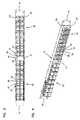
- FIGS. 1 and 2are front elevation and front perspective views, respectively, of an embodiment of a patch panel in accordance with the present invention including a plurality of electrical connector assemblies.
- FIGS. 3 and 4are rear elevation and rear perspective views, respectively, of the patch panel shown in FIG. 1 .
- FIG. 5is a side view of the patch panel shown in FIG. 1 .
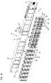
- FIG. 6is an exploded, front perspective view of the patch panel of FIGS. 1-5 in accordance with the present invention including a plurality of electrical connector assemblies.
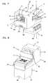
- FIGS. 7 and 8are front perspective and rear perspective views, respectively, of an embodiment of an electrical connector assembly in accordance with the present invention.
- FIGS. 9-13are front perspective, front, side, bottom, and rear views, respectively, of an embodiment of an angled jack housing in accordance with the present invention.
- FIGS. 14-16are front perspective, rear perspective, and side views, respectively, of an embodiment of a spring insert in accordance with the present invention.
- FIGS. 17 and 18are front perspective and rear perspective views, respectively, of an embodiment of a front entry clip in accordance with the present invention.
- FIGS. 19-21are front perspective, rear perspective, and side views, respectively, of an embodiment of a cover in accordance with the present invention.
- FIGS. 22-24are front perspective, rear perspective, and front views, respectively, of an embodiment of a modular jack in accordance with the present invention.
- FIGS. 25-27are perspective views illustrating assembly of an embodiment of a spring insert, including a plurality of springs and a front entry clip, in accordance with the present invention.
- FIGS. 28 and 29are perspective views illustrating assembly of an embodiment of a spring insert and a modular jack onto a board in accordance with the present invention.
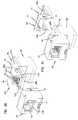
- FIGS. 30 and 31are perspective views illustrating assembly of an embodiment of a housing and cover onto an angled jack in accordance with the present invention.
- FIGS. 32-35are top views illustrating coupling of an embodiment of an electrical connector assembly to a patch panel in accordance with the present invention.
- FIGS. 1 and 2an embodiment of a patch panel 10 with a front surface 11 is illustrated including mounting portions 14 which allow the patch panel 10 to be mounted to such structures as a rack or cabinet.
- a plurality of electrical connector assemblies 15are shown coupled to the patch panel 10 .
- Each of the electrical connector assemblies 15comprises a first jack 16 and a second jack 36 electrically connected to one another.
- Each jack 16 and 36receives a patch cord plug (not shown).
- Each jack 16 and 36is disposed at an angle to the panel so that each patch cord is angled toward the same end of the patch panel.
- the first jackis an angled jack 16 since it mounts to the patch panel in an angled configuration.
- the second jackis a modular jack 36 assembled to the angled jack 16 to form the connector assembly 15 (see FIGS. 3 - 4 ).
- both the angled jack 16 and the modular jack 36are RJ-45 type jacks.
- RJ-45 type jacksRJ-45 type jacks.
- other types of jacksmay also be used without departing from the spirit of the invention.
- Each angled jack 16defines a port 17 including a latch groove 18 .
- Each angled jack 16is positioned at an angle with respect to the front surface 11 of the patch panel 10 .
- the angled jacks 16are positioned at a 45-degree angle with respect to the front surface 11 , however other similar angles may also be used.
- the ports 17 of each of the angled jacks 16 or a group of angled jacks 16may be oriented in different directions, such as first angled jack group 12 and oppositely-oriented second angled jack group 13 .
- Each angled jack 16may accommodate a plug (not shown) such as a patch cord used to interconnect two jacks.
- Each plugincludes conductive contacts for making electrical contact with the springs of each jack.
- each of the ports 17 of each of the angled jacks 16is positioned such that the latch groove 18 is at an outermost area of the angled jack 16 .
- a plug inserted into port 17presents a plug clip on the plug that is spaced from the front surface 11 of the patch panel 10 . This provides the user's thumb or finger with easy access to the plug clip when the plug is released from the port 17 . The ease in accessing the plug clip facilitates rapid changeover and minimizes downtime.
- each of the electrical connector assemblies 15includes a modular jack 36 defining a port 37 with a latch groove 38 .
- the modular jack 36may accommodate a plug (not shown), and each modular jack 36 is positioned at an angle with respect to the rear surface 31 of the patch panel 10 .
- each modular jack 36is positioned at a 45-degree angle with respect to the rear surface 31 .
- each the ports 37 of each modular jack or group of modular jacks 36may be oriented in different directions, such as first modular jack group 32 and oppositely-oriented second modular jack group 33 .
- each of the latch grooves 38 on each of the modular jacks 36are positioned on the modular jack 36 so as to be spaced from the rear surface 31 of the patch panel 10 to allow for easy removal of a plug clip of a plug inserted into the port 37 .
- Cable managementmay be increased due to the angled jacks on both sides of the patch panel, reducing the twisting forces exerted on the patch cords.
- the unique configurationmay allow for a greater density of jacks on the panel as well.
- FIG. 5A side view of the patch panel 10 and plurality of electrical connector assemblies 15 is shown in FIG. 5 . Both ports 17 and 37 are visible in the side view since the end assemblies face partially toward the side, as well as other assemblies in the group.
- Each electrical connector assembly 15may be inserted into a connector location 61 defined by the patch panel 10 generally in a direction 5 , such that notches 64 formed in a housing 61 of the angled jack 16 are seated on a first side 66 of the connector location 61 and a pair of shoulders 62 and a latch 63 formed on the housing 61 of the angled jack 16 are positioned to surround a second side 68 of the connector location 61 .
- each of the electrical connector assemblies 15may be coupled to the patch panel 10 such that the angled jack 16 is positioned at a 45-degree angle with respect to the front surface 11 and the modular jack 36 is positioned at a 45-degree angle with respect to the rear surface 31 of the patch panel 10 .
- the housing 61further includes a top 72 and a front 73 in which the port 17 is defined, as well as springs 74 that make electrical contact with complementary conductors on a plug (not shown).
- the housing 61also defines apertures 75 into which locking tabs 76 and 77 are engaged (both locking tabs 76 and 77 are discussed below).
- a board 78on which both the angled jack 16 and the modular jack 36 are mounted and a cover 71 coupled to the board and the housing 61 .
- the angled jack 16(and specifically the port 17 ) is positioned at an angle relative to the modular jack (and specifically the port 37 ).
- the port 17 of the angled jack 16is positioned at a 90-degree angle with respect to the port 37 of the modular jack 36 .
- Other anglesmay also be used without departing from the spirit of the invention.
- the port 17is positioned relative to the port 36 such that a line of plug insertion X—X drawn through the port 17 intersects a line of plug insertion Y—Y drawn through the port 37 at a point outside both the angled jack 16 and the modular jack 36 .
- the electrical connector assembly 15may be coupled to the patch panel 10 as shown in FIG. 6 .
- the housing 61 of the angled jack 16is shown in greater detail in FIGS. 9-13.
- the notches 64 , the shoulders 62 , and the latch 63can be seen in greater detail in FIGS. 11 and 12.
- the shoulders 62 and the latch 63are formed adjacent the front 72 and a bottom 110 of the housing 61
- the notches 63are formed opposite and adjacent the top 72 and a rear 111 of the housing 61 .
- the rear 111 of the housing 61is shown, including rails 131 defining grooves 132 between the rails 131 and the bottom 110 of the housing 61 .
- FIGS. 14-16Shown in FIGS. 14-16 is a spring insert 130 in accordance with an example embodiment of the present invention.
- the spring insert 130comprises a front 131 and sides 132 and 134 , as well as railways 133 defined by the sides 132 and 134 .
- the locking tabs 76are positioned on an outer surface of each side 132 and 134 and are sized to fit into the apertures 75 defined in the housing 61 .
- a comb 135with a plurality of grooves in which a plurality of springs (not shown) may be disposed within.
- a window 137is defined between the comb 135 and a bottom 138 of the spring insert 130 .
- FIGS. 17 and 18a front entry clip 170 is shown in accordance with an example embodiment of the present invention.
- the front entry clip 170includes a front 171 and a plurality of arms 172 extending rearwardly from the front 171 .
- the arms 172correspond to the grooves formed by the comb 135 of the spring insert 130 .
- the front entry clip 170is sized so as to fit in the window 137 and the arms 172 are formed so as to engage the grooves in the comb 135 .
- the cover 71is illustrated in FIGS. 19-21, including an angled portion 201 and a modular portion 202 .
- the cover 71generally functions to protect the board 78 (described below) from dust and other debris.
- the angled portion 201protects the rear 111 and springs 74 of the angled jack 16 and the modular portion 202 protects the electrical connections made with the modular jack 36 .
- Railways 192are defined in inner surfaces 193 of the cover 71 sized so as to slidingly engage the board 78 , as shown below.
- the locking tabs 77are positioned to engage the apertures 75 on the housing 61 .
- the modular jack 36is shown including the port 37 and the latch groove 38 .
- the modular jack 36further includes pins 232 used to make electrical connection with the board 78 and tabs 231 with increased circumferential ends 233 to engage apertures 281 defined by the board 78 so as to hold the modular jack 36 in place.
- a commercially available RJ-45 jackmade by Stewart Connector Systems with model number SS-7188V-A-NF, is used for the modular jack 36 .
- jacksmay also be used instead of jacks 16 and 36 without departing from the spirit of the invention.
- the alternative jackscould be mounted together in any convenient manner and provided with retention structure for positioning each jack angled toward the same end of the patch panel.
- FIGS. 25-31generally illustrate an example method for assembling the electrical connector assembly 15 in accordance with the present invention.
- the springs 74are inserted into the grooves of the comb 135 of the spring insert 130 .
- different types of springs 74may be used, including springs bent to different angles and springs with contact portions running in opposite directions.
- a spring tip 261 of each spring 74extends below the bottom 138 of the spring insert 130 .
- the front entry clip 170is inserted into the spring insert 130 in the window 137 , so that at least a portion of the arms 172 of the front entry clip 170 slidingly engage the spring insert 130 .
- the spring insert 130is coupled to the board 78 at a first end 288 .
- the board 78may be constructed of any dielectric material, such as PCB, and includes electrical connections 286 and electrical connections 287 defined by the board 78 . Further included are tracings 284 , which may be etched into the board 78 , so as to connect the electrical connections 286 with the electrical connections 287 in a variety of arrangements.
- the spring insert 130is coupled to a top surface 282 of the board 78 by inserting the spring tips 261 of the springs 74 into the electrical connections 286 and soldering the spring tips 261 to the board 78 .
- the modular jack 36is coupled to the board 78 on a bottom surface 283 and a second end 289 by inserting spring tips 290 of the pins 232 into the electrical connections 287 and inserting the tabs 231 into the apertures 281 defined by the board 78 .
- the spring tips 290are soldered to the board 78 .
- the increased circumferential ends 233 of the tabs 231are sized so as to engage an inner circumference of the apertures 281 to hold the modular jack 36 and the board 78 together.
- the housing 61is slidingly engaged with the board 78 and the spring insert 130 .
- the first end 288 of the boardis slide along the grooves 132 of the housing 61 , and the railways 133 of the spring insert 130 are slid along the complementary rails 131 of the housing 61 .
- the housing 61is slid toward the second end 289 of the board 78 until the locking tabs 76 of the spring insert 130 are disposed within the apertures 75 defined by the housing 61 , so as to lock the housing 61 into place. In this locked position, the springs 74 are accessible through the port 17 .
- the cover 71is slidingly engaged on the board 78 by sliding the second end 289 of the board 78 into the railways 192 until the locking tabs 77 engage the apertures 75 in the housing 61 , thereby locking the cover 71 into place.
- the modular portion 202 of the cover 71 positioned in this mannerprotects the electrical connections 287 and the tracings 284 on the board 78 as well as the pins 232 .
- the angled portion 201 of the cover 71protects the springs 74 of the angled jack 16 .
- FIGS. 32-35illustrated an example method for coupling the electrical connector assembly 15 with the patch panel 10 .
- the electrical connector assembly 15is positioned generally adjacent the front surface 11 of the patch panel 10 with the modular jack 36 aligned with one of the connector locations 61 between the first side 66 and the second side 68 .
- the electrical connector assembly 15is then moved perpendicularly with respect to the patch panel 10 in a direction A so that the modular jack 36 is moved partially through the connector location 61 .
- the electrical connector assembly 15is slightly turned and moved in a direction B until, as is shown in FIG. 34, the modular jack 36 and the modular portion 202 of the cover 71 clear the patch panel 10 .
- the electrical connector assembly 15is then moved at a direction C until notch 64 on the angled jack 16 engages the first side 66 of the connector location 61 and the latch 63 passes through the connector location 61 and the shoulders 62 engages the front surface 11 of the patch panel 10 .
- the latch 63is positioned to contact the rear surface 31 of the patch panel 10 and the shoulders engage the front surface 11 so as to surround the first side 66 of the connector location 61 to releasably lock the electrical connector assembly 15 into place.
- the connector assemblies 15 in FIGS. 32-35are angled in the same direction, such as for group 13 in FIG. 1.
- a second group, group 12 in FIG. 1can be angled in the opposite direction by following a similar method, but in an opposite direction.
Landscapes
- Engineering & Computer Science (AREA)
- Computer Networks & Wireless Communication (AREA)
- Coupling Device And Connection With Printed Circuit (AREA)
- Details Of Connecting Devices For Male And Female Coupling (AREA)
- Connector Housings Or Holding Contact Members (AREA)
Abstract
Description
Claims (16)
Priority Applications (4)
| Application Number | Priority Date | Filing Date | Title |
|---|---|---|---|
| US10/645,760US6761585B2 (en) | 2001-11-16 | 2003-08-19 | Angled RJ to RJ patch panel |
| US10/860,177US7066771B2 (en) | 2001-11-16 | 2004-06-03 | Angled RJ to RJ patch panel |
| US11/382,106US7241182B2 (en) | 2001-11-16 | 2006-05-08 | Angled RJ to RJ patch panel |
| US11/774,609US7686658B2 (en) | 2001-11-16 | 2007-07-08 | Angled RJ to RJ patch panel |
Applications Claiming Priority (2)
| Application Number | Priority Date | Filing Date | Title |
|---|---|---|---|
| US09/991,077US6736670B2 (en) | 2001-11-16 | 2001-11-16 | Angled RJ to RJ patch panel |
| US10/645,760US6761585B2 (en) | 2001-11-16 | 2003-08-19 | Angled RJ to RJ patch panel |
Related Parent Applications (1)
| Application Number | Title | Priority Date | Filing Date |
|---|---|---|---|
| US09/991,077ContinuationUS6736670B2 (en) | 2001-11-16 | 2001-11-16 | Angled RJ to RJ patch panel |
Related Child Applications (1)
| Application Number | Title | Priority Date | Filing Date |
|---|---|---|---|
| US10/860,177ContinuationUS7066771B2 (en) | 2001-11-16 | 2004-06-03 | Angled RJ to RJ patch panel |
Publications (2)
| Publication Number | Publication Date |
|---|---|
| US20040038594A1 US20040038594A1 (en) | 2004-02-26 |
| US6761585B2true US6761585B2 (en) | 2004-07-13 |
Family
ID=25536847
Family Applications (5)
| Application Number | Title | Priority Date | Filing Date |
|---|---|---|---|
| US09/991,077Expired - LifetimeUS6736670B2 (en) | 2001-11-16 | 2001-11-16 | Angled RJ to RJ patch panel |
| US10/645,760Expired - LifetimeUS6761585B2 (en) | 2001-11-16 | 2003-08-19 | Angled RJ to RJ patch panel |
| US10/860,177Expired - LifetimeUS7066771B2 (en) | 2001-11-16 | 2004-06-03 | Angled RJ to RJ patch panel |
| US11/382,106Expired - Fee RelatedUS7241182B2 (en) | 2001-11-16 | 2006-05-08 | Angled RJ to RJ patch panel |
| US11/774,609Expired - Fee RelatedUS7686658B2 (en) | 2001-11-16 | 2007-07-08 | Angled RJ to RJ patch panel |
Family Applications Before (1)
| Application Number | Title | Priority Date | Filing Date |
|---|---|---|---|
| US09/991,077Expired - LifetimeUS6736670B2 (en) | 2001-11-16 | 2001-11-16 | Angled RJ to RJ patch panel |
Family Applications After (3)
| Application Number | Title | Priority Date | Filing Date |
|---|---|---|---|
| US10/860,177Expired - LifetimeUS7066771B2 (en) | 2001-11-16 | 2004-06-03 | Angled RJ to RJ patch panel |
| US11/382,106Expired - Fee RelatedUS7241182B2 (en) | 2001-11-16 | 2006-05-08 | Angled RJ to RJ patch panel |
| US11/774,609Expired - Fee RelatedUS7686658B2 (en) | 2001-11-16 | 2007-07-08 | Angled RJ to RJ patch panel |
Country Status (4)
| Country | Link |
|---|---|
| US (5) | US6736670B2 (en) |
| AU (1) | AU2002366075B2 (en) |
| GB (2) | GB2415549B (en) |
| WO (1) | WO2003044902A1 (en) |
Cited By (29)
| Publication number | Priority date | Publication date | Assignee | Title |
|---|---|---|---|---|
| US20050197005A1 (en)* | 2004-03-04 | 2005-09-08 | Darrell Bentley | High-density multi-port-module patch panel system |
| US20050282442A1 (en)* | 2004-06-18 | 2005-12-22 | Hyland James H | Electrical adapter assembly |
| US20060089010A1 (en)* | 2004-10-26 | 2006-04-27 | Jung-Wen Chang | Connector assembly |
| USD545766S1 (en)* | 2004-06-16 | 2007-07-03 | Adc Gmbh | Patch panel |
| US7278880B1 (en)* | 2006-03-31 | 2007-10-09 | Hsing Chau Industrial Co., Ltd. | Jumper board |
| US7288001B1 (en)* | 2006-09-20 | 2007-10-30 | Ortronics, Inc. | Electrically isolated shielded multiport connector assembly |
| US20080102709A1 (en)* | 2006-10-27 | 2008-05-01 | Intel Corporation | Multiport ethernet connector |
| US20080280500A1 (en)* | 2007-05-07 | 2008-11-13 | Martich Mark E | Connector assembly for use with plugs and preterminated cables |
| US20090163043A1 (en)* | 2007-12-21 | 2009-06-25 | Yannick Demers | Patch panel with angled module |
| USD624504S1 (en)* | 2009-12-29 | 2010-09-28 | ENGINUITY Communications Corp. | Patch panel assembly |
| US20110217867A1 (en)* | 2009-03-03 | 2011-09-08 | Adc Gmbh | Consolidation point enclosure |
| US8182294B2 (en) | 2007-05-07 | 2012-05-22 | Ortronics, Inc. | Connector assembly and related methods of use |
| US8600208B2 (en) | 2010-08-24 | 2013-12-03 | Adc Telecommunications, Inc. | Fiber optic telecommunications module |
| US8758047B2 (en) | 2007-05-07 | 2014-06-24 | Ortronics, Inc. | Port replication assembly with adapter cable and related methods of use |
| US20140370226A1 (en)* | 2013-06-17 | 2014-12-18 | Cisco Technology, Inc. | Panel assembly |
| US9146374B2 (en) | 2012-09-28 | 2015-09-29 | Adc Telecommunications, Inc. | Rapid deployment packaging for optical fiber |
| US20150370028A1 (en)* | 2010-06-02 | 2015-12-24 | Tyco Electronics Corporation | Switch rack system |
| US9223094B2 (en) | 2012-10-05 | 2015-12-29 | Tyco Electronics Nederland Bv | Flexible optical circuit, cassettes, and methods |
| US9435975B2 (en) | 2013-03-15 | 2016-09-06 | Commscope Technologies Llc | Modular high density telecommunications frame and chassis system |
| US9535229B2 (en) | 2011-10-07 | 2017-01-03 | Commscope Technologies Llc | Fiber optic cassette, system, and method |
| US9722380B1 (en)* | 2016-07-22 | 2017-08-01 | Rockwell Automation Technologies, Inc. | Network distribution adapter for a motor control center |
| US9885845B2 (en)* | 2015-01-15 | 2018-02-06 | Commscope, Inc. Of North Carolina | Module and assembly for fiber optic interconnections |
| US9910236B2 (en) | 2008-08-29 | 2018-03-06 | Corning Optical Communications LLC | High density and bandwidth fiber optic apparatuses and related equipment and methods |
| US10094996B2 (en) | 2008-08-29 | 2018-10-09 | Corning Optical Communications, Llc | Independently translatable modules and fiber optic equipment trays in fiber optic equipment |
| US11294136B2 (en) | 2008-08-29 | 2022-04-05 | Corning Optical Communications LLC | High density and bandwidth fiber optic apparatuses and related equipment and methods |
| US11372165B2 (en) | 2011-09-12 | 2022-06-28 | Commscope Technologies Llc | Flexible lensed optical interconnect device for signal distribution |
| US11409068B2 (en) | 2017-10-02 | 2022-08-09 | Commscope Technologies Llc | Fiber optic circuit and preparation method |
| US11592628B2 (en) | 2012-09-28 | 2023-02-28 | Commscope Technologies Llc | Fiber optic cassette |
| US12339511B2 (en) | 2020-03-31 | 2025-06-24 | Commscope Technologies Llc | Fiber optic cable management systems and methods |
Families Citing this family (45)
| Publication number | Priority date | Publication date | Assignee | Title |
|---|---|---|---|---|
| US6736670B2 (en)* | 2001-11-16 | 2004-05-18 | Adc Telecommunications, Inc. | Angled RJ to RJ patch panel |
| US6790096B2 (en)* | 2001-12-28 | 2004-09-14 | Hon Hai Precision Ind. Co., Ltd. | Cable assembly having arrangement for organizing cable |
| US7112090B2 (en)* | 2003-05-14 | 2006-09-26 | Panduit Corp. | High density keystone jack patch panel |
| DE102004022865B4 (en)* | 2004-05-06 | 2010-01-07 | Mc Technology Gmbh | RJ-45 coupling |
| EP1761905A1 (en)* | 2004-05-31 | 2007-03-14 | Jason Andrew Roper | Computer network security |
| US7335049B2 (en)* | 2004-09-15 | 2008-02-26 | 3M Innovative Properties Company | Connector assembly for housing insulation displacement elements |
| USD559186S1 (en)* | 2004-09-20 | 2008-01-08 | Rit Technologies Ltd. | High-density patch panel |
| US7748032B2 (en)* | 2004-09-30 | 2010-06-29 | Citrix Systems, Inc. | Method and apparatus for associating tickets in a ticket hierarchy |
| US7094095B1 (en)* | 2005-02-25 | 2006-08-22 | Panduit Corp. | Stair-stepped angled patch panel |
| JP4613725B2 (en)* | 2005-07-19 | 2011-01-19 | 住友電装株式会社 | Split connector |
| US7234944B2 (en)* | 2005-08-26 | 2007-06-26 | Panduit Corp. | Patch field documentation and revision systems |
| USD542240S1 (en)* | 2005-09-08 | 2007-05-08 | Leviton Manufacturing Co., Inc. | Patch panel |
| US7300308B2 (en)* | 2005-09-09 | 2007-11-27 | Leviton Manufacturing Co., Inc. | Patch panel |
| DE102006003752A1 (en)* | 2006-01-25 | 2007-09-20 | Mc Technology Gmbh | clutch |
| US7343078B2 (en)* | 2006-06-29 | 2008-03-11 | Commscope Solutions Properties, Llc | Patch panels with communications connectors that are rotatable about a vertical axis |
| GB2451385A (en)* | 2006-06-29 | 2009-01-28 | Commscope Inc | Patch panels with communications connectors that are rotatable about a vertical axis |
| US7335056B1 (en)* | 2006-10-19 | 2008-02-26 | Adc Telecommunications, Inc. | RJ to RJ swing panel |
| US7488205B2 (en)* | 2006-12-13 | 2009-02-10 | Commscope, Inc. Of North Carolina | Fixed angled patch panel |
| CN101663797B (en)* | 2007-03-29 | 2013-01-23 | 西蒙公司 | Communication connector |
| US7601024B2 (en)* | 2007-05-07 | 2009-10-13 | Ortronics, Inc. | Shielded connector assembly for preterminated systems |
| EP2019580B1 (en)* | 2007-07-12 | 2012-12-19 | Panduit Corporation | Accessory Bracket |
| US9038973B2 (en)* | 2007-07-12 | 2015-05-26 | Panduit Corp. | Accessory bracket |
| MX2010001515A (en)* | 2007-08-09 | 2010-03-10 | Belden Cdt Canada Inc | TELESCOPIC CONNECTOR ASSEMBLY. |
| GB2451849A (en)* | 2007-08-14 | 2009-02-18 | Brand Rex Ltd | Patch panel having angled jacks |
| WO2009058928A1 (en)* | 2007-10-30 | 2009-05-07 | The Siemon Company | Vertical patching system |
| CA123805S (en)* | 2007-12-14 | 2009-02-25 | Fiber Connections Inc | Patch panel |
| CN201178025Y (en)* | 2008-01-05 | 2009-01-07 | 富士康(昆山)电脑接插件有限公司 | Magnetic coil module and electrical connector provided with the module |
| US7978951B2 (en)* | 2008-03-28 | 2011-07-12 | Adc Telecommunications, Inc. | Bulkhead with angled openings and method |
| US20100093210A1 (en)* | 2008-10-10 | 2010-04-15 | Kunshan Jiahua Electronics Co., Ltd. | Coaxial electrical connector |
| US7762839B2 (en)* | 2008-12-22 | 2010-07-27 | Surtec Industries, Inc. | Patch panel assembly |
| US7896692B2 (en)* | 2009-05-15 | 2011-03-01 | Leviton Manufacturing Co., Inc. | Method of improving isolation between circuits on a printed circuit board |
| US8744228B2 (en)* | 2009-05-22 | 2014-06-03 | Commscope, Inc. Of North Carolina | Telecommunications patching system with cable management system and related cable management equipment |
| US8585437B2 (en) | 2011-11-10 | 2013-11-19 | Jyh Eng Technology Co., Ltd. | Angle panel |
| DE202011052046U1 (en) | 2011-11-21 | 2012-01-27 | Jyh Eng Technology Co., Ltd. | Angle Steckfeld |
| WO2013112858A1 (en)* | 2012-01-27 | 2013-08-01 | Go!Foton Holdings, Inc. | Patch panel assembly |
| JP5259858B1 (en)* | 2012-05-16 | 2013-08-07 | 株式会社東芝 | Connectors, circuit modules and electronic equipment |
| US8747150B1 (en)* | 2012-12-24 | 2014-06-10 | Jyh Eng Technology Co., Ltd. | Multidirectional modular jack and face panel mounting structure |
| CN112018687A (en)* | 2013-12-31 | 2020-12-01 | 福州欧冠创新工业设计有限公司 | Hexagonal socket for reducing accumulated turning angle of pipeline |
| US10291969B2 (en) | 2017-02-14 | 2019-05-14 | Go!Foton Holdings, Inc. | Rear cable management |
| US11228819B1 (en)* | 2020-06-30 | 2022-01-18 | Go!Foton Holdings, Inc. | Easy access patch panel |
| US12022245B2 (en) | 2020-06-30 | 2024-06-25 | Go!Foton Holdings, Inc. | Easy access patch panel |
| EP3971622A1 (en) | 2020-07-02 | 2022-03-23 | Go!Foton Holdings, Inc. | Intelligent optical switch |
| AU2021301276A1 (en)* | 2020-07-02 | 2023-02-23 | Commscope Technologies Llc | Universal jack opening |
| WO2022006549A1 (en)* | 2020-07-02 | 2022-01-06 | Commscope Technologies Llc | Telecommunications jack adapter |
| EP4063929A1 (en)* | 2021-01-18 | 2022-09-28 | Sterlite Technologies Limited | Enclosure with converging ports |
Citations (48)
| Publication number | Priority date | Publication date | Assignee | Title |
|---|---|---|---|---|
| US4290664A (en) | 1979-09-28 | 1981-09-22 | Communications Systems, Inc. | Multiple outlet telephone line adapter |
| US4367908A (en) | 1980-06-05 | 1983-01-11 | Akzona Incorporated | Electrical connector coupling |
| US4379609A (en) | 1981-03-09 | 1983-04-12 | Western Electric Company, Inc. | Modular cord coupler jack having a disconnection encumbrance |
| US4438998A (en) | 1982-03-05 | 1984-03-27 | Amp Incorporated | Modular plug-dial modular jack adaptor |
| US4460234A (en) | 1981-09-18 | 1984-07-17 | Virginia Patent Development Corporation | Double-ended modular jack |
| US4593966A (en) | 1984-09-17 | 1986-06-10 | Communications Systems, Inc. | Modular telephone line coupler |
| US4657330A (en) | 1984-02-06 | 1987-04-14 | Thomas & Betts Corporation | Field installable modular telephone connector |
| US4806117A (en) | 1987-08-21 | 1989-02-21 | Amp Incorporated | Modular plug coupler |
| US4904209A (en) | 1987-12-04 | 1990-02-27 | Amp Incorporated | Modular plug coupler |
| US4905275A (en) | 1989-02-06 | 1990-02-27 | Porta Systems Corp. | Laminar type telephone protector block and interconnectable modular elements therefor |
| US4944698A (en) | 1988-12-27 | 1990-07-31 | The Siemon Company | Dual modular jack adapter |
| US5030123A (en) | 1989-03-24 | 1991-07-09 | Adc Telecommunications, Inc. | Connector and patch panel for digital video and data |
| US5044981A (en) | 1990-04-18 | 1991-09-03 | Reliance Comm/Tec Corporation | Snap-on stacking telephone jack |
| US5074801A (en) | 1990-10-26 | 1991-12-24 | The Siemon Company | Modular jack patching device |
| US5129842A (en) | 1991-04-08 | 1992-07-14 | Digital Equipment Corporation | Modular patch panel |
| US5139445A (en) | 1990-12-07 | 1992-08-18 | The Siemon Company | Modular test adapter |
| US5161988A (en) | 1991-02-13 | 1992-11-10 | Rit Technologies Ltd. | Patching panel |
| US5178554A (en) | 1990-10-26 | 1993-01-12 | The Siemon Company | Modular jack patching device |
| US5269708A (en) | 1993-03-03 | 1993-12-14 | Adc Telecommunications, Inc. | Patch panel for high speed twisted pair |
| US5328390A (en) | 1992-09-01 | 1994-07-12 | Hubbell Incorporated | Modular telecommunication jack adapter |
| US5366388A (en) | 1990-06-27 | 1994-11-22 | Digital Equipment Corporation | Wiring distribution system and devices for building wiring |
| EP0718926A2 (en) | 1994-12-23 | 1996-06-26 | AT&T Corp. | Modular cross-connect system |
| US5531612A (en) | 1993-12-14 | 1996-07-02 | Goodall; Roy J. | Multi-port modular jack assembly |
| US5658166A (en)* | 1990-06-27 | 1997-08-19 | Digital Equipment Corporation | Modular coupler arrangement for use in a building wiring distribution system |
| US5685742A (en) | 1995-11-28 | 1997-11-11 | Molex Incorporated | Electrical connector |
| US5721776A (en) | 1996-03-21 | 1998-02-24 | Northern Telecom Limited | Telephone line connector |
| US5836786A (en) | 1996-05-21 | 1998-11-17 | The Whitaker Corporation | Patch panel having snap together construction |
| US5931703A (en) | 1997-02-04 | 1999-08-03 | Hubbell Incorporated | Low crosstalk noise connector for telecommunication systems |
| USD417434S (en) | 1998-12-28 | 1999-12-07 | Hon Hai Precision Ind. Co., Ltd. | Modular jack |
| WO1999063628A1 (en) | 1998-06-05 | 1999-12-09 | Adc Telecommunications, Inc. | Telecommunications patch panel with angled connector modules and method of assembling such a panel |
| US6031909A (en) | 1998-03-19 | 2000-02-29 | Lucent Technologies Inc. | Modular jack housing |
| US6036547A (en) | 1998-03-05 | 2000-03-14 | Berg Technology, Inc. | Double deck gang jack exhibiting suppressed mutual crosstalk |
| USD421964S (en) | 1998-10-14 | 2000-03-28 | Accton Technology Corporation | Hub |
| US6053764A (en) | 1998-06-30 | 2000-04-25 | Lucent Technologies Inc. | Patch panel and interlocking module |
| US6068520A (en) | 1997-03-13 | 2000-05-30 | Berg Technology, Inc. | Low profile double deck connector with improved cross talk isolation |
| US6123577A (en) | 1996-02-06 | 2000-09-26 | Energy Transformation Systems, Inc. | Lan patch panel and wall mount unit assembly |
| US6142834A (en) | 1999-04-23 | 2000-11-07 | Liao; Sheng-Hsin | Electric jack with a pivoted cover |
| US6146192A (en)* | 1999-03-31 | 2000-11-14 | Adc Telecommunications, Inc. | Bulkhead connector system including angled adapter |
| US6146207A (en) | 1998-03-23 | 2000-11-14 | Framatome Connectors International | Coupling element for two plugs, adapted male and female elements and coupling device obtained |
| US6168474B1 (en) | 1999-06-04 | 2001-01-02 | Lucent Technologies Inc. | Communications connector having crosstalk compensation |
| US6176741B1 (en) | 1998-04-20 | 2001-01-23 | Pulse Engineering, Inc. | Modular Microelectronic connector and method for manufacturing same |
| US6193560B1 (en) | 2000-03-03 | 2001-02-27 | Tyco Electronics Corporation | Connector assembly with side-by-side terminal arrays |
| US6234832B1 (en) | 1996-09-12 | 2001-05-22 | Berg Technology, Inc. | Double row modular gang jack for board edge application |
| US6296534B1 (en) | 2000-08-16 | 2001-10-02 | Hon Hai Precision Ind. Co., Ltd. | Encapsulated electrical adapter assembly and method of producing the same |
| US6302742B1 (en) | 2000-06-02 | 2001-10-16 | John Ray Berst | Electrical interface panel |
| US6319066B2 (en) | 2000-03-31 | 2001-11-20 | Hon Hai Precision Ind. Co., Ltd. | Compact electrical adapter for mounting to a panel connector of a computer |
| US6352447B1 (en) | 2000-03-24 | 2002-03-05 | Techsonic Industries, Inc. | Cable bundle connector |
| US6358093B1 (en) | 2001-02-07 | 2002-03-19 | Adc Telecommunications, Inc. | Normal through jack and method |
Family Cites Families (18)
| Publication number | Priority date | Publication date | Assignee | Title |
|---|---|---|---|---|
| US421964A (en)* | 1890-02-25 | Horse-boot | ||
| US417434A (en)* | 1889-12-17 | Julius ffjedltlcir ferdixaxd praxz lowe | ||
| DE421965C (en)* | 1924-03-14 | 1925-11-24 | Foerderanlagen Ernst Heckel M | Prismatic support composed of several similar parts |
| US4995688A (en)* | 1989-07-31 | 1991-02-26 | Adc Telecommunications, Inc. | Optical fiber distribution frame |
| US5127082A (en)* | 1991-03-22 | 1992-06-30 | The Siemon Company | Fiber optic patch panel |
| US5295869A (en)* | 1992-12-18 | 1994-03-22 | The Siemon Company | Electrically balanced connector assembly |
| US5892870A (en)* | 1995-11-16 | 1999-04-06 | Fiber Connections Inc. | Fibre optic cable connector |
| DE29521330U1 (en)* | 1995-12-09 | 1997-01-09 | BTR Blumberger Telefon- und Relaisbau Albert Metz, 78176 Blumberg | Adapter for the connection of telecommunication and data terminals |
| US5708742A (en)* | 1996-06-18 | 1998-01-13 | Northern Telecom Limited | Combinations of printed circuit boards and face plates |
| US6123834A (en)* | 1997-04-18 | 2000-09-26 | Exxon Chemical Patents Inc. | Catalytic upgrade of naphtha |
| US6167183A (en)* | 1997-05-30 | 2000-12-26 | Hubbell Incorporated | Low profile communications outlet box |
| AUPP224298A0 (en) | 1998-03-06 | 1998-04-02 | Power And Digital Instruments Pty. Ltd. | Improved manner of electrical connection |
| GB9824415D0 (en)* | 1998-11-07 | 1998-12-30 | Raychem Sa Nv | A panel for supporting a plurality of fibre optic connectors |
| US6334792B1 (en)* | 1999-01-15 | 2002-01-01 | Adc Telecommunications, Inc. | Connector including reduced crosstalk spring insert |
| USD421965S (en)* | 1999-05-10 | 2000-03-28 | Ditel, Inc. | Fiber optic cable connector plate |
| JP4087046B2 (en)* | 2000-09-06 | 2008-05-14 | ヒロセ電機株式会社 | Optical cable adapter or connector and its mounting member |
| TWI231869B (en)* | 2000-11-29 | 2005-05-01 | Fci Sa | Angled optical connector mounting assembly |
| US6736670B2 (en)* | 2001-11-16 | 2004-05-18 | Adc Telecommunications, Inc. | Angled RJ to RJ patch panel |
- 2001
- 2001-11-16USUS09/991,077patent/US6736670B2/ennot_activeExpired - Lifetime
- 2002
- 2002-11-13GBGB0516478Apatent/GB2415549B/ennot_activeExpired - Fee Related
- 2002-11-13WOPCT/US2002/036481patent/WO2003044902A1/ennot_activeApplication Discontinuation
- 2002-11-13AUAU2002366075Apatent/AU2002366075B2/ennot_activeCeased
- 2002-11-13GBGB0411323Apatent/GB2397703C/ennot_activeExpired - Fee Related
- 2003
- 2003-08-19USUS10/645,760patent/US6761585B2/ennot_activeExpired - Lifetime
- 2004
- 2004-06-03USUS10/860,177patent/US7066771B2/ennot_activeExpired - Lifetime
- 2006
- 2006-05-08USUS11/382,106patent/US7241182B2/ennot_activeExpired - Fee Related
- 2007
- 2007-07-08USUS11/774,609patent/US7686658B2/ennot_activeExpired - Fee Related
Patent Citations (49)
| Publication number | Priority date | Publication date | Assignee | Title |
|---|---|---|---|---|
| US4290664A (en) | 1979-09-28 | 1981-09-22 | Communications Systems, Inc. | Multiple outlet telephone line adapter |
| US4367908A (en) | 1980-06-05 | 1983-01-11 | Akzona Incorporated | Electrical connector coupling |
| US4379609A (en) | 1981-03-09 | 1983-04-12 | Western Electric Company, Inc. | Modular cord coupler jack having a disconnection encumbrance |
| US4460234A (en) | 1981-09-18 | 1984-07-17 | Virginia Patent Development Corporation | Double-ended modular jack |
| US4438998A (en) | 1982-03-05 | 1984-03-27 | Amp Incorporated | Modular plug-dial modular jack adaptor |
| US4657330A (en) | 1984-02-06 | 1987-04-14 | Thomas & Betts Corporation | Field installable modular telephone connector |
| US4593966A (en) | 1984-09-17 | 1986-06-10 | Communications Systems, Inc. | Modular telephone line coupler |
| US4806117A (en) | 1987-08-21 | 1989-02-21 | Amp Incorporated | Modular plug coupler |
| US4904209A (en) | 1987-12-04 | 1990-02-27 | Amp Incorporated | Modular plug coupler |
| US4944698A (en) | 1988-12-27 | 1990-07-31 | The Siemon Company | Dual modular jack adapter |
| US4905275A (en) | 1989-02-06 | 1990-02-27 | Porta Systems Corp. | Laminar type telephone protector block and interconnectable modular elements therefor |
| US5030123A (en) | 1989-03-24 | 1991-07-09 | Adc Telecommunications, Inc. | Connector and patch panel for digital video and data |
| US5044981A (en) | 1990-04-18 | 1991-09-03 | Reliance Comm/Tec Corporation | Snap-on stacking telephone jack |
| US5658166A (en)* | 1990-06-27 | 1997-08-19 | Digital Equipment Corporation | Modular coupler arrangement for use in a building wiring distribution system |
| US5366388A (en) | 1990-06-27 | 1994-11-22 | Digital Equipment Corporation | Wiring distribution system and devices for building wiring |
| US5178554A (en) | 1990-10-26 | 1993-01-12 | The Siemon Company | Modular jack patching device |
| US5074801A (en) | 1990-10-26 | 1991-12-24 | The Siemon Company | Modular jack patching device |
| US5139445A (en) | 1990-12-07 | 1992-08-18 | The Siemon Company | Modular test adapter |
| US5161988A (en) | 1991-02-13 | 1992-11-10 | Rit Technologies Ltd. | Patching panel |
| US5129842A (en) | 1991-04-08 | 1992-07-14 | Digital Equipment Corporation | Modular patch panel |
| US5328390A (en) | 1992-09-01 | 1994-07-12 | Hubbell Incorporated | Modular telecommunication jack adapter |
| US5269708A (en) | 1993-03-03 | 1993-12-14 | Adc Telecommunications, Inc. | Patch panel for high speed twisted pair |
| US5531612A (en) | 1993-12-14 | 1996-07-02 | Goodall; Roy J. | Multi-port modular jack assembly |
| US5639261A (en) | 1994-12-23 | 1997-06-17 | Lucent Technologies Inc. | Modular cross-connect system |
| EP0718926A2 (en) | 1994-12-23 | 1996-06-26 | AT&T Corp. | Modular cross-connect system |
| US5685742A (en) | 1995-11-28 | 1997-11-11 | Molex Incorporated | Electrical connector |
| US6123577A (en) | 1996-02-06 | 2000-09-26 | Energy Transformation Systems, Inc. | Lan patch panel and wall mount unit assembly |
| US5721776A (en) | 1996-03-21 | 1998-02-24 | Northern Telecom Limited | Telephone line connector |
| US5836786A (en) | 1996-05-21 | 1998-11-17 | The Whitaker Corporation | Patch panel having snap together construction |
| US6234832B1 (en) | 1996-09-12 | 2001-05-22 | Berg Technology, Inc. | Double row modular gang jack for board edge application |
| US5931703A (en) | 1997-02-04 | 1999-08-03 | Hubbell Incorporated | Low crosstalk noise connector for telecommunication systems |
| US6068520A (en) | 1997-03-13 | 2000-05-30 | Berg Technology, Inc. | Low profile double deck connector with improved cross talk isolation |
| US6036547A (en) | 1998-03-05 | 2000-03-14 | Berg Technology, Inc. | Double deck gang jack exhibiting suppressed mutual crosstalk |
| US6031909A (en) | 1998-03-19 | 2000-02-29 | Lucent Technologies Inc. | Modular jack housing |
| US6146207A (en) | 1998-03-23 | 2000-11-14 | Framatome Connectors International | Coupling element for two plugs, adapted male and female elements and coupling device obtained |
| US6176741B1 (en) | 1998-04-20 | 2001-01-23 | Pulse Engineering, Inc. | Modular Microelectronic connector and method for manufacturing same |
| WO1999063628A1 (en) | 1998-06-05 | 1999-12-09 | Adc Telecommunications, Inc. | Telecommunications patch panel with angled connector modules and method of assembling such a panel |
| US6053764A (en) | 1998-06-30 | 2000-04-25 | Lucent Technologies Inc. | Patch panel and interlocking module |
| USD421964S (en) | 1998-10-14 | 2000-03-28 | Accton Technology Corporation | Hub |
| USD417434S (en) | 1998-12-28 | 1999-12-07 | Hon Hai Precision Ind. Co., Ltd. | Modular jack |
| US6146192A (en)* | 1999-03-31 | 2000-11-14 | Adc Telecommunications, Inc. | Bulkhead connector system including angled adapter |
| US6142834A (en) | 1999-04-23 | 2000-11-07 | Liao; Sheng-Hsin | Electric jack with a pivoted cover |
| US6168474B1 (en) | 1999-06-04 | 2001-01-02 | Lucent Technologies Inc. | Communications connector having crosstalk compensation |
| US6193560B1 (en) | 2000-03-03 | 2001-02-27 | Tyco Electronics Corporation | Connector assembly with side-by-side terminal arrays |
| US6352447B1 (en) | 2000-03-24 | 2002-03-05 | Techsonic Industries, Inc. | Cable bundle connector |
| US6319066B2 (en) | 2000-03-31 | 2001-11-20 | Hon Hai Precision Ind. Co., Ltd. | Compact electrical adapter for mounting to a panel connector of a computer |
| US6302742B1 (en) | 2000-06-02 | 2001-10-16 | John Ray Berst | Electrical interface panel |
| US6296534B1 (en) | 2000-08-16 | 2001-10-02 | Hon Hai Precision Ind. Co., Ltd. | Encapsulated electrical adapter assembly and method of producing the same |
| US6358093B1 (en) | 2001-02-07 | 2002-03-19 | Adc Telecommunications, Inc. | Normal through jack and method |
Non-Patent Citations (19)
| Title |
|---|
| "Angled Entry Jack Shielded Cat. 6," Tyco Electronics, 1 page (Mar. 2, 2001). |
| "Coupler Assembly, 6 Position, Right Angle," AMP Incorporated, 1 page (Jul. 29, 1984). |
| ADC Telecommunications, Inc., "ADC REZ(TM), Home Networking Solutions" 100318PR, Sep. 2000, 2 pages. |
| ADC Telecommunications, Inc., "ADC REZ™, Home Networking Solutions" 100318PR, Sep. 2000, 2 pages. |
| ADC Telecommunications, Inc., "Enterprise(TM) Network Essentials for ADC" M168, May 2000, 8 pages. |
| ADC Telecommunications, Inc., "Enterprise(TM) Structural Connectivity System Patch Panels" 100054PR, Dec. 2000, 21 pages. |
| ADC Telecommunications, Inc., "Enterprise™ Network Essentials for ADC" M168, May 2000, 8 pages. |
| ADC Telecommunications, Inc., "Enterprise™ Structural Connectivity System Patch Panels" 100054PR, Dec. 2000, 21 pages. |
| ADC Telecommunications, Inc., "Network Connectivity Solutions" M143, Feb. 2001, Front Cover page, Table of Contents (2 pages ), pp. 1-41, and Back Cover page. |
| ATS, Inc., "UTP Slim Line(TM) Adapter Category 5E Products," http://www.atsats.com/products/slim.htm, 3 pages (Printed Jul. 18, 2001). |
| ATS, Inc., "UTP Slim Line™ Adapter Category 5E Products," http://www.atsats.com/products/slim.htm, 3 pages (Printed Jul. 18, 2001). |
| L-com(R) Connectivity Products, "L-com ECF Product Literature (excepts)," 5 pages (date unknown). |
| L-com® Connectivity Products, "L-com ECF Product Literature (excepts)," 5 pages (date unknown). |
| Ortronics, Inc., "Specialty Panels and Hubs," http://www.ortronics.com/products/products/m_patch_panels, 5 pages (2000). |
| Photographs of ATS Slimline(TM) Adapter EIA T568 A/B PS-Cat 5+, P/N C5RJT155. |
| Photographs of ATS Slimline™ Adapter EIA T568 A/B PS-Cat 5+, P/N C5RJT155. |
| Stewart Connector Systems, Inc., "71 Series. AngleJack Vertical Modular Jacks," http://www.stewartconnector.com/products/modular/angeljack.htm, 6 pages (1999). |
| The Siemon Company, Catalog 1999, Front Cover page, Table of Contents, pp. 1.3-1.5, and Back Cover page (1999). |
| UNICOM Electric, Inc., "Category 5c and 5 Feed-Thru Panels," http://www.unicomlink.com/wiring/feed.html, 1 page (1995). |
Cited By (71)
| Publication number | Priority date | Publication date | Assignee | Title |
|---|---|---|---|---|
| US6974348B2 (en)* | 2004-03-04 | 2005-12-13 | Commscope Solutions Properties, Llc. | High-density multi-port-module patch panel system |
| US20050197005A1 (en)* | 2004-03-04 | 2005-09-08 | Darrell Bentley | High-density multi-port-module patch panel system |
| USD545766S1 (en)* | 2004-06-16 | 2007-07-03 | Adc Gmbh | Patch panel |
| US20050282442A1 (en)* | 2004-06-18 | 2005-12-22 | Hyland James H | Electrical adapter assembly |
| US7048550B2 (en)* | 2004-06-18 | 2006-05-23 | Hon Hai Precision Ind. Co., Ltd. | Electrical adapter assembly |
| US20060089010A1 (en)* | 2004-10-26 | 2006-04-27 | Jung-Wen Chang | Connector assembly |
| US7278880B1 (en)* | 2006-03-31 | 2007-10-09 | Hsing Chau Industrial Co., Ltd. | Jumper board |
| US7288001B1 (en)* | 2006-09-20 | 2007-10-30 | Ortronics, Inc. | Electrically isolated shielded multiport connector assembly |
| US7473144B2 (en)* | 2006-10-27 | 2009-01-06 | Intel Corporation | Multiport ethernet connector |
| US20080102709A1 (en)* | 2006-10-27 | 2008-05-01 | Intel Corporation | Multiport ethernet connector |
| US8182294B2 (en) | 2007-05-07 | 2012-05-22 | Ortronics, Inc. | Connector assembly and related methods of use |
| US8758047B2 (en) | 2007-05-07 | 2014-06-24 | Ortronics, Inc. | Port replication assembly with adapter cable and related methods of use |
| US7628657B2 (en)* | 2007-05-07 | 2009-12-08 | Ortronics, Inc. | Connector assembly for use with plugs and preterminated cables |
| US20090311916A1 (en)* | 2007-05-07 | 2009-12-17 | Ortronics, Inc | Subassembly containing contact leads |
| US7695328B2 (en) | 2007-05-07 | 2010-04-13 | Ortronics, Inc. | Subassembly containing contact leads |
| US20080280500A1 (en)* | 2007-05-07 | 2008-11-13 | Martich Mark E | Connector assembly for use with plugs and preterminated cables |
| WO2009079776A1 (en)* | 2007-12-21 | 2009-07-02 | Belden Cdt Canada Inc. | Patch panel with angled module |
| US20090163043A1 (en)* | 2007-12-21 | 2009-06-25 | Yannick Demers | Patch panel with angled module |
| US11294136B2 (en) | 2008-08-29 | 2022-04-05 | Corning Optical Communications LLC | High density and bandwidth fiber optic apparatuses and related equipment and methods |
| US10606014B2 (en) | 2008-08-29 | 2020-03-31 | Corning Optical Communications LLC | Independently translatable modules and fiber optic equipment trays in fiber optic equipment |
| US11609396B2 (en) | 2008-08-29 | 2023-03-21 | Corning Optical Communications LLC | High density and bandwidth fiber optic apparatuses and related equipment and methods |
| US10094996B2 (en) | 2008-08-29 | 2018-10-09 | Corning Optical Communications, Llc | Independently translatable modules and fiber optic equipment trays in fiber optic equipment |
| US11294135B2 (en) | 2008-08-29 | 2022-04-05 | Corning Optical Communications LLC | High density and bandwidth fiber optic apparatuses and related equipment and methods |
| US12072545B2 (en) | 2008-08-29 | 2024-08-27 | Corning Optical Communications LLC | High density and bandwidth fiber optic apparatuses and related equipment and methods |
| US11092767B2 (en) | 2008-08-29 | 2021-08-17 | Corning Optical Communications LLC | High density and bandwidth fiber optic apparatuses and related equipment and methods |
| US11086089B2 (en) | 2008-08-29 | 2021-08-10 | Corning Optical Communications LLC | High density and bandwidth fiber optic apparatuses and related equipment and methods |
| US10852499B2 (en) | 2008-08-29 | 2020-12-01 | Corning Optical Communications LLC | High density and bandwidth fiber optic apparatuses and related equipment and methods |
| US11754796B2 (en) | 2008-08-29 | 2023-09-12 | Corning Optical Communications LLC | Independently translatable modules and fiber optic equipment trays in fiber optic equipment |
| US10564378B2 (en) | 2008-08-29 | 2020-02-18 | Corning Optical Communications LLC | High density and bandwidth fiber optic apparatuses and related equipment and methods |
| US10459184B2 (en) | 2008-08-29 | 2019-10-29 | Corning Optical Communications LLC | High density and bandwidth fiber optic apparatuses and related equipment and methods |
| US10444456B2 (en) | 2008-08-29 | 2019-10-15 | Corning Optical Communications LLC | High density and bandwidth fiber optic apparatuses and related equipment and methods |
| US10422971B2 (en) | 2008-08-29 | 2019-09-24 | Corning Optical Communicatinos LLC | High density and bandwidth fiber optic apparatuses and related equipment and methods |
| US10416405B2 (en) | 2008-08-29 | 2019-09-17 | Corning Optical Communications LLC | Independently translatable modules and fiber optic equipment trays in fiber optic equipment |
| US10222570B2 (en) | 2008-08-29 | 2019-03-05 | Corning Optical Communications LLC | Independently translatable modules and fiber optic equipment trays in fiber optic equipment |
| US9910236B2 (en) | 2008-08-29 | 2018-03-06 | Corning Optical Communications LLC | High density and bandwidth fiber optic apparatuses and related equipment and methods |
| US10126514B2 (en) | 2008-08-29 | 2018-11-13 | Corning Optical Communications, Llc | Independently translatable modules and fiber optic equipment trays in fiber optic equipment |
| US10120153B2 (en) | 2008-08-29 | 2018-11-06 | Corning Optical Communications, Llc | Independently translatable modules and fiber optic equipment trays in fiber optic equipment |
| US20110217867A1 (en)* | 2009-03-03 | 2011-09-08 | Adc Gmbh | Consolidation point enclosure |
| US8292660B2 (en) | 2009-03-03 | 2012-10-23 | Adc Gmbh | Consolidation point enclosure |
| USD624504S1 (en)* | 2009-12-29 | 2010-09-28 | ENGINUITY Communications Corp. | Patch panel assembly |
| US9632272B2 (en)* | 2010-06-02 | 2017-04-25 | Commscope Technologies Llc | Switch rack system |
| US20150370028A1 (en)* | 2010-06-02 | 2015-12-24 | Tyco Electronics Corporation | Switch rack system |
| US8600208B2 (en) | 2010-08-24 | 2013-12-03 | Adc Telecommunications, Inc. | Fiber optic telecommunications module |
| US11372165B2 (en) | 2011-09-12 | 2022-06-28 | Commscope Technologies Llc | Flexible lensed optical interconnect device for signal distribution |
| US11061197B2 (en) | 2011-10-07 | 2021-07-13 | Commscope Technologies Llc | Fiber optic cassette, system, and method |
| US10578821B2 (en) | 2011-10-07 | 2020-03-03 | Commscope Technologies Llc | Fiber optic cassette, system, and method |
| US9535229B2 (en) | 2011-10-07 | 2017-01-03 | Commscope Technologies Llc | Fiber optic cassette, system, and method |
| US11561356B2 (en) | 2011-10-07 | 2023-01-24 | Commscope Technologies Llc | Fiber optic cassette, system, and method |
| US9952400B2 (en) | 2011-10-07 | 2018-04-24 | Commscope Technologies Llc | Fiber optic cassette, system, and method |
| US11592628B2 (en) | 2012-09-28 | 2023-02-28 | Commscope Technologies Llc | Fiber optic cassette |
| US9470869B2 (en) | 2012-09-28 | 2016-10-18 | Commscope Technologies Llc | Rapid deployment packaging for optical fiber |
| US9927591B2 (en) | 2012-09-28 | 2018-03-27 | Commscope Technologies Llc | Rapid deployment packaging for optical fiber |
| US9146374B2 (en) | 2012-09-28 | 2015-09-29 | Adc Telecommunications, Inc. | Rapid deployment packaging for optical fiber |
| US9874711B2 (en) | 2012-10-05 | 2018-01-23 | Commscope Asia Holdings B.V. | Flexible optical circuit, cassettes, and methods |
| US10955633B2 (en) | 2012-10-05 | 2021-03-23 | Commscope Asia Holdings B.V. | Flexible optical circuit, cassettes, and methods |
| US9223094B2 (en) | 2012-10-05 | 2015-12-29 | Tyco Electronics Nederland Bv | Flexible optical circuit, cassettes, and methods |
| US10317638B2 (en) | 2012-10-05 | 2019-06-11 | Commscope Asia Holdings B.V. | Flexible optical circuit, cassettes, and methods |
| US11573389B2 (en) | 2012-10-05 | 2023-02-07 | Commscope Asia Holdings B.V. | Flexible optical circuit, cassettes, and methods |
| US12130487B2 (en) | 2012-10-05 | 2024-10-29 | Commscope Asia Holdings B.V. | Flexible optical circuit, cassettes, and methods |
| US9435975B2 (en) | 2013-03-15 | 2016-09-06 | Commscope Technologies Llc | Modular high density telecommunications frame and chassis system |
| US9952398B2 (en) | 2013-03-15 | 2018-04-24 | Commscope Technologies Llc | Modular high density telecommunications frame and chassis system |
| US10473875B2 (en) | 2013-03-15 | 2019-11-12 | Commscope Technologies Llc | Modular high density telecommunications frame and chassis system |
| US9247319B2 (en)* | 2013-06-17 | 2016-01-26 | Cisco Technology, Inc. | Panel assembly |
| US20140370226A1 (en)* | 2013-06-17 | 2014-12-18 | Cisco Technology, Inc. | Panel assembly |
| US9885845B2 (en)* | 2015-01-15 | 2018-02-06 | Commscope, Inc. Of North Carolina | Module and assembly for fiber optic interconnections |
| US10613285B2 (en) | 2015-01-15 | 2020-04-07 | Commscope, Inc. Of North Carolina | Module and assembly for fiber optic interconnections |
| US9722380B1 (en)* | 2016-07-22 | 2017-08-01 | Rockwell Automation Technologies, Inc. | Network distribution adapter for a motor control center |
| US11609400B2 (en) | 2017-10-02 | 2023-03-21 | Commscope Technologies Llc | Fiber optic circuit and preparation method |
| US11409068B2 (en) | 2017-10-02 | 2022-08-09 | Commscope Technologies Llc | Fiber optic circuit and preparation method |
| US12276858B2 (en) | 2017-10-02 | 2025-04-15 | Commscope Technologies Llc | Fiber optic circuit and preparation method |
| US12339511B2 (en) | 2020-03-31 | 2025-06-24 | Commscope Technologies Llc | Fiber optic cable management systems and methods |
Also Published As
| Publication number | Publication date |
|---|---|
| US20080108253A1 (en) | 2008-05-08 |
| GB2415549B (en) | 2006-06-14 |
| HK1067237A1 (en) | 2005-04-01 |
| WO2003044902A1 (en) | 2003-05-30 |
| HK1085573A1 (en) | 2006-08-25 |
| US20030096536A1 (en) | 2003-05-22 |
| US6736670B2 (en) | 2004-05-18 |
| AU2002366075B2 (en) | 2008-06-12 |
| HK1085057A1 (en) | 2006-08-11 |
| US7686658B2 (en) | 2010-03-30 |
| US20040219829A1 (en) | 2004-11-04 |
| US7066771B2 (en) | 2006-06-27 |
| US20060194471A1 (en) | 2006-08-31 |
| GB2397703A (en) | 2004-07-28 |
| GB2397703C (en) | 2006-06-13 |
| GB2415549A (en) | 2005-12-28 |
| AU2002366075A1 (en) | 2003-06-10 |
| US7241182B2 (en) | 2007-07-10 |
| GB2397703B (en) | 2006-05-31 |
| US20040038594A1 (en) | 2004-02-26 |
| GB0516478D0 (en) | 2005-09-14 |
| GB0411323D0 (en) | 2004-06-23 |
Similar Documents
| Publication | Publication Date | Title |
|---|---|---|
| US6761585B2 (en) | Angled RJ to RJ patch panel | |
| US7455548B2 (en) | Rotatable connector modules with inverted jacks | |
| CN100449876C (en) | Telecommunication terminal block | |
| US7503810B1 (en) | Board edge termination back-end connection assemblies and communications jacks including such assemblies | |
| US7857635B2 (en) | Board edge termination back-end connection assemblies and communications connectors including such assemblies | |
| EP2137794B1 (en) | Modular connector with reduced termination variability and improved performance | |
| EP0939455A2 (en) | Low cross talk connector configuration | |
| US6371794B1 (en) | Telecommunications plug and adapter | |
| JPH07201379A (en) | Patch connector | |
| US9893470B2 (en) | Telecommunications cabling system, and electrical connection module shielding interface therefor | |
| JP2003522389A (en) | Vertical and right angle modular outlets | |
| GB2420665A (en) | Angled connector assembly for patch panel |
Legal Events
| Date | Code | Title | Description |
|---|---|---|---|
| STCF | Information on status: patent grant | Free format text:PATENTED CASE | |
| FPAY | Fee payment | Year of fee payment:4 | |
| REMI | Maintenance fee reminder mailed | ||
| FPAY | Fee payment | Year of fee payment:8 | |
| AS | Assignment | Owner name:TYCO ELECTRONICS SERVICES GMBH, SWITZERLAND Free format text:ASSIGNMENT OF ASSIGNORS INTEREST;ASSIGNOR:ADC TELECOMMUNICATIONS, INC.;REEL/FRAME:036060/0174 Effective date:20110930 | |
| AS | Assignment | Owner name:COMMSCOPE EMEA LIMITED, IRELAND Free format text:ASSIGNMENT OF ASSIGNORS INTEREST;ASSIGNOR:TYCO ELECTRONICS SERVICES GMBH;REEL/FRAME:036956/0001 Effective date:20150828 | |
| AS | Assignment | Owner name:COMMSCOPE TECHNOLOGIES LLC, NORTH CAROLINA Free format text:ASSIGNMENT OF ASSIGNORS INTEREST;ASSIGNOR:COMMSCOPE EMEA LIMITED;REEL/FRAME:037012/0001 Effective date:20150828 | |
| AS | Assignment | Owner name:JPMORGAN CHASE BANK, N.A., AS COLLATERAL AGENT, ILLINOIS Free format text:PATENT SECURITY AGREEMENT (TERM);ASSIGNOR:COMMSCOPE TECHNOLOGIES LLC;REEL/FRAME:037513/0709 Effective date:20151220 Owner name:JPMORGAN CHASE BANK, N.A., AS COLLATERAL AGENT, ILLINOIS Free format text:PATENT SECURITY AGREEMENT (ABL);ASSIGNOR:COMMSCOPE TECHNOLOGIES LLC;REEL/FRAME:037514/0196 Effective date:20151220 Owner name:JPMORGAN CHASE BANK, N.A., AS COLLATERAL AGENT, IL Free format text:PATENT SECURITY AGREEMENT (ABL);ASSIGNOR:COMMSCOPE TECHNOLOGIES LLC;REEL/FRAME:037514/0196 Effective date:20151220 Owner name:JPMORGAN CHASE BANK, N.A., AS COLLATERAL AGENT, IL Free format text:PATENT SECURITY AGREEMENT (TERM);ASSIGNOR:COMMSCOPE TECHNOLOGIES LLC;REEL/FRAME:037513/0709 Effective date:20151220 | |
| FPAY | Fee payment | Year of fee payment:12 | |
| AS | Assignment | Owner name:ALLEN TELECOM LLC, ILLINOIS Free format text:RELEASE BY SECURED PARTY;ASSIGNOR:JPMORGAN CHASE BANK, N.A.;REEL/FRAME:048840/0001 Effective date:20190404 Owner name:REDWOOD SYSTEMS, INC., NORTH CAROLINA Free format text:RELEASE BY SECURED PARTY;ASSIGNOR:JPMORGAN CHASE BANK, N.A.;REEL/FRAME:048840/0001 Effective date:20190404 Owner name:ANDREW LLC, NORTH CAROLINA Free format text:RELEASE BY SECURED PARTY;ASSIGNOR:JPMORGAN CHASE BANK, N.A.;REEL/FRAME:048840/0001 Effective date:20190404 Owner name:COMMSCOPE TECHNOLOGIES LLC, NORTH CAROLINA Free format text:RELEASE BY SECURED PARTY;ASSIGNOR:JPMORGAN CHASE BANK, N.A.;REEL/FRAME:048840/0001 Effective date:20190404 Owner name:COMMSCOPE, INC. OF NORTH CAROLINA, NORTH CAROLINA Free format text:RELEASE BY SECURED PARTY;ASSIGNOR:JPMORGAN CHASE BANK, N.A.;REEL/FRAME:048840/0001 Effective date:20190404 Owner name:ANDREW LLC, NORTH CAROLINA Free format text:RELEASE BY SECURED PARTY;ASSIGNOR:JPMORGAN CHASE BANK, N.A.;REEL/FRAME:049260/0001 Effective date:20190404 Owner name:REDWOOD SYSTEMS, INC., NORTH CAROLINA Free format text:RELEASE BY SECURED PARTY;ASSIGNOR:JPMORGAN CHASE BANK, N.A.;REEL/FRAME:049260/0001 Effective date:20190404 Owner name:ALLEN TELECOM LLC, ILLINOIS Free format text:RELEASE BY SECURED PARTY;ASSIGNOR:JPMORGAN CHASE BANK, N.A.;REEL/FRAME:049260/0001 Effective date:20190404 Owner name:COMMSCOPE TECHNOLOGIES LLC, NORTH CAROLINA Free format text:RELEASE BY SECURED PARTY;ASSIGNOR:JPMORGAN CHASE BANK, N.A.;REEL/FRAME:049260/0001 Effective date:20190404 Owner name:COMMSCOPE, INC. OF NORTH CAROLINA, NORTH CAROLINA Free format text:RELEASE BY SECURED PARTY;ASSIGNOR:JPMORGAN CHASE BANK, N.A.;REEL/FRAME:049260/0001 Effective date:20190404 | |
| AS | Assignment | Owner name:JPMORGAN CHASE BANK, N.A., NEW YORK Free format text:ABL SECURITY AGREEMENT;ASSIGNORS:COMMSCOPE, INC. OF NORTH CAROLINA;COMMSCOPE TECHNOLOGIES LLC;ARRIS ENTERPRISES LLC;AND OTHERS;REEL/FRAME:049892/0396 Effective date:20190404 Owner name:WILMINGTON TRUST, NATIONAL ASSOCIATION, AS COLLATE Free format text:PATENT SECURITY AGREEMENT;ASSIGNOR:COMMSCOPE TECHNOLOGIES LLC;REEL/FRAME:049892/0051 Effective date:20190404 Owner name:JPMORGAN CHASE BANK, N.A., NEW YORK Free format text:TERM LOAN SECURITY AGREEMENT;ASSIGNORS:COMMSCOPE, INC. OF NORTH CAROLINA;COMMSCOPE TECHNOLOGIES LLC;ARRIS ENTERPRISES LLC;AND OTHERS;REEL/FRAME:049905/0504 Effective date:20190404 Owner name:WILMINGTON TRUST, NATIONAL ASSOCIATION, AS COLLATERAL AGENT, CONNECTICUT Free format text:PATENT SECURITY AGREEMENT;ASSIGNOR:COMMSCOPE TECHNOLOGIES LLC;REEL/FRAME:049892/0051 Effective date:20190404 | |
| AS | Assignment | Owner name:WILMINGTON TRUST, DELAWARE Free format text:SECURITY INTEREST;ASSIGNORS:ARRIS SOLUTIONS, INC.;ARRIS ENTERPRISES LLC;COMMSCOPE TECHNOLOGIES LLC;AND OTHERS;REEL/FRAME:060752/0001 Effective date:20211115 | |
| AS | Assignment | Owner name:RUCKUS WIRELESS, LLC (F/K/A RUCKUS WIRELESS, INC.), NORTH CAROLINA Free format text:RELEASE OF SECURITY INTEREST AT REEL/FRAME 049905/0504;ASSIGNOR:JPMORGAN CHASE BANK, N.A., AS COLLATERAL AGENT;REEL/FRAME:071477/0255 Effective date:20241217 Owner name:COMMSCOPE TECHNOLOGIES LLC, NORTH CAROLINA Free format text:RELEASE OF SECURITY INTEREST AT REEL/FRAME 049905/0504;ASSIGNOR:JPMORGAN CHASE BANK, N.A., AS COLLATERAL AGENT;REEL/FRAME:071477/0255 Effective date:20241217 Owner name:COMMSCOPE, INC. OF NORTH CAROLINA, NORTH CAROLINA Free format text:RELEASE OF SECURITY INTEREST AT REEL/FRAME 049905/0504;ASSIGNOR:JPMORGAN CHASE BANK, N.A., AS COLLATERAL AGENT;REEL/FRAME:071477/0255 Effective date:20241217 Owner name:ARRIS SOLUTIONS, INC., NORTH CAROLINA Free format text:RELEASE OF SECURITY INTEREST AT REEL/FRAME 049905/0504;ASSIGNOR:JPMORGAN CHASE BANK, N.A., AS COLLATERAL AGENT;REEL/FRAME:071477/0255 Effective date:20241217 Owner name:ARRIS TECHNOLOGY, INC., NORTH CAROLINA Free format text:RELEASE OF SECURITY INTEREST AT REEL/FRAME 049905/0504;ASSIGNOR:JPMORGAN CHASE BANK, N.A., AS COLLATERAL AGENT;REEL/FRAME:071477/0255 Effective date:20241217 Owner name:ARRIS ENTERPRISES LLC (F/K/A ARRIS ENTERPRISES, INC.), NORTH CAROLINA Free format text:RELEASE OF SECURITY INTEREST AT REEL/FRAME 049905/0504;ASSIGNOR:JPMORGAN CHASE BANK, N.A., AS COLLATERAL AGENT;REEL/FRAME:071477/0255 Effective date:20241217 |