US6761503B2 - Splined member for use in a slip joint and method of manufacturing the same - Google Patents
Splined member for use in a slip joint and method of manufacturing the sameDownload PDFInfo
- Publication number
- US6761503B2 US6761503B2US10/131,752US13175202AUS6761503B2US 6761503 B2US6761503 B2US 6761503B2US 13175202 AUS13175202 AUS 13175202AUS 6761503 B2US6761503 B2US 6761503B2
- Authority
- US
- United States
- Prior art keywords
- slip joint
- grooves
- rods
- longitudinally extending
- joint defined
- Prior art date
- Legal status (The legal status is an assumption and is not a legal conclusion. Google has not performed a legal analysis and makes no representation as to the accuracy of the status listed.)
- Expired - Fee Related
Links
Images


Classifications
- F—MECHANICAL ENGINEERING; LIGHTING; HEATING; WEAPONS; BLASTING
- F16—ENGINEERING ELEMENTS AND UNITS; GENERAL MEASURES FOR PRODUCING AND MAINTAINING EFFECTIVE FUNCTIONING OF MACHINES OR INSTALLATIONS; THERMAL INSULATION IN GENERAL
- F16C—SHAFTS; FLEXIBLE SHAFTS; ELEMENTS OR CRANKSHAFT MECHANISMS; ROTARY BODIES OTHER THAN GEARING ELEMENTS; BEARINGS
- F16C3/00—Shafts; Axles; Cranks; Eccentrics
- F16C3/02—Shafts; Axles
- F16C3/03—Shafts; Axles telescopic
- F16C3/035—Shafts; Axles telescopic with built-in bearings
- F—MECHANICAL ENGINEERING; LIGHTING; HEATING; WEAPONS; BLASTING
- F16—ENGINEERING ELEMENTS AND UNITS; GENERAL MEASURES FOR PRODUCING AND MAINTAINING EFFECTIVE FUNCTIONING OF MACHINES OR INSTALLATIONS; THERMAL INSULATION IN GENERAL
- F16D—COUPLINGS FOR TRANSMITTING ROTATION; CLUTCHES; BRAKES
- F16D3/00—Yielding couplings, i.e. with means permitting movement between the connected parts during the drive
- F16D3/02—Yielding couplings, i.e. with means permitting movement between the connected parts during the drive adapted to specific functions
- F16D3/06—Yielding couplings, i.e. with means permitting movement between the connected parts during the drive adapted to specific functions specially adapted to allow axial displacement
- F16D3/065—Yielding couplings, i.e. with means permitting movement between the connected parts during the drive adapted to specific functions specially adapted to allow axial displacement by means of rolling elements
- Y—GENERAL TAGGING OF NEW TECHNOLOGICAL DEVELOPMENTS; GENERAL TAGGING OF CROSS-SECTIONAL TECHNOLOGIES SPANNING OVER SEVERAL SECTIONS OF THE IPC; TECHNICAL SUBJECTS COVERED BY FORMER USPC CROSS-REFERENCE ART COLLECTIONS [XRACs] AND DIGESTS
- Y10—TECHNICAL SUBJECTS COVERED BY FORMER USPC
- Y10T—TECHNICAL SUBJECTS COVERED BY FORMER US CLASSIFICATION
- Y10T403/00—Joints and connections
- Y10T403/70—Interfitted members
- Y10T403/7026—Longitudinally splined or fluted rod
- Y10T403/7031—Rod designed to be manipulable, e.g., twistable, within coupling for quick disconnect
- Y—GENERAL TAGGING OF NEW TECHNOLOGICAL DEVELOPMENTS; GENERAL TAGGING OF CROSS-SECTIONAL TECHNOLOGIES SPANNING OVER SEVERAL SECTIONS OF THE IPC; TECHNICAL SUBJECTS COVERED BY FORMER USPC CROSS-REFERENCE ART COLLECTIONS [XRACs] AND DIGESTS
- Y10—TECHNICAL SUBJECTS COVERED BY FORMER USPC
- Y10T—TECHNICAL SUBJECTS COVERED BY FORMER US CLASSIFICATION
- Y10T403/00—Joints and connections
- Y10T403/70—Interfitted members
- Y10T403/7026—Longitudinally splined or fluted rod
- Y10T403/7033—Longitudinally splined or fluted rod including a lock or retainer
Definitions
- This inventionrelates in general to slip joints, such as are commonly used in vehicle drive train systems, for transmitting rotational force or torque between telescoping members, while accommodating a limited amount of relative axial movement therebetween.
- this inventionrelates to an improved structure for a splined member that is adapted for use in such a slip joint.
- a drive train systemfor transmitting rotational power from an engine/transmission assembly to an axle assembly so as to rotatably drive one or more wheels of the vehicle.
- a typical drive train systemincludes a driveshaft assembly that is connected between an output shaft of the engine/transmission assembly and an input shaft of the axle assembly.
- a first universal jointis connected between the output shaft of the engine/transmission assembly and a first end of the driveshaft assembly, while a second universal joint is connected between a second end of the driveshaft assembly and the input shaft of the axle assembly.
- the universal jointsprovide a rotational driving connection from the output shaft of the engine/transmission assembly through the driveshaft assembly to the input shaft of the axle assembly, while accommodating a limited amount of angular misalignment between the rotational axes thereof.
- a typical slip jointincludes male and female telescoping members having respective pluralities of splines formed thereon.
- the male splined memberhas a plurality of outwardly extending splines formed on the outer surface thereof that cooperate with a plurality of inwardly extending splines formed on the inner surface of the female splined member.
- the cooperating splines of the male and female membersprovide a rotational driving connection through the slip joint, while permitting a limited amount of relative axial movement therebetween.
- the slip jointmay be provided at the ends of the driveshaft assembly or in the interior thereof, as desired.
- splined membersare often formed by a machining process, wherein material is removed from a member to form splines therein.
- the memberis initially formed having a surface of predetermined size and shape.
- a cutting toolsuch as a hobbing tool
- the material that remains on the memberbecomes the plurality of splines.
- the splinesare usually formed having relatively square faces, i.e., faces that are generally flat and extend generally radially relative to the rotational axis of the member.
- the splined memberis coated with a material having a relatively low coefficient of friction.
- the low friction coatingis provided to minimize the amount of force that is required to effect relative movement between the two splined members. Also, the low friction coating provides a relatively tight fit between the cooperating splines of the two splined members, thus minimizing any undesirable looseness therebetween while continuing to allow free axial movement.
- the splined membercan include a female tubular member having an inner surface provided with a plurality of longitudinally extending grooves that are sized and spaced in accordance with a desired number and position of splines to be formed.
- a elongated rodis disposed in each of the longitudinally extending grooves formed in the inner surface of the female tubular member.
- a quantity of positioning materialis provided within spaces provided between the elongated rods and the longitudinally extending grooves. The positioning material is then hardened to support the elongated rods in the longitudinally extending grooves to define a plurality of inwardly extending splines in the female splined member.
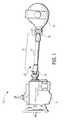
- FIG. 1is a schematic side elevational view of a vehicle drive train system including a slip joint in accordance with this invention.
- FIG. 2is an enlarged, exploded perspective view, partially broken away, of the slip joint illustrated in FIG. 1 .
- FIG. 3is a sectional elevational view of a hollow cylindrical member that can be used to formed a female splined member for the slip joint illustrated in FIGS. 1 and 2.
- FIG. 4is a sectional elevational view of the hollow cylindrical member illustrated in FIG. 3 after having a plurality of longitudinally extending grooves formed therein.
- FIG. 5is a sectional elevational view of a male positioning mandrel having a plurality of elongated rods supported thereon.
- FIG. 6is a sectional elevational view showing the male positioning mandrel and the elongated rods illustrated in FIG. 5 positioned concentrically within the hollow cylindrical member illustrated in FIG. 4 .
- FIG. 7is a sectional elevational view showing the female splined member that has been formed after a quantity of positioning material has been introduced by the male positioning member between the elongated rods and the longitudinally extending grooves of the hollow cylindrical member.
- FIG. 8is a sectional elevational view of the assembled slip joint illustrated in FIGS. 1 and 2 .
- FIG. 1a drive train system, indicated generally at 10 , in accordance with this invention.
- the illustrated drive train system 10which is intended to be representative of any drive train system (vehicular or otherwise) for transferring rotational power from a source to a driven device, includes a transmission 12 having an output shaft (not shown) that is connected to an input shaft (not shown) of an axle assembly 14 by a driveshaft assembly 15 .
- the transmission 12 and the axle assembly 14are conventional in the art.
- the driveshaft assembly 15includes a hollow cylindrical driveshaft tube 16 that extends from a front end adjacent to the transmission 12 to a rear end adjacent to the axle assembly 14 .
- the driveshaft assembly 15further includes a pair of universal joints 18 for rotatably connecting the output shaft of the transmission 12 to the front end of the driveshaft assembly 15 and for rotatably connecting the rear end of the driveshaft assembly 15 to the input shaft of the axle assembly 14 .
- the universal joints 18are also conventional in the art.
- a slip joint, indicated generally at 20is provided for connecting the rear end of the front universal joint 18 to the front end of the driveshaft tube 16 .
- the structure of the slip joint 20is illustrated in detail in FIG. 2 .
- the slip joint 20includes a female splined member, indicated generally at 22 , including a female tubular member 22 a having a plurality of inwardly extending splines that are defined by a plurality of circumferentially spaced, elongated rods 23 .
- the elongated rods 23extend radially inwardly from an inner surface of the female tubular member 22 a to define the splines.
- the female splined member 22further has a pair of spaced apart yoke arms (not shown in FIG. 2) formed thereon that extend axially from the female tubular member 22 a and are connected to the front universal joint 18 .
- the female splined member 22is typically referred to as a slip yoke.
- the slip joint 20also includes a male member, indicated generally at 24 , that includes a cylindrical body portion 24 a having a plurality of circumferentially spaced, longitudinally extending grooves 24 b formed in an outer surface thereof.
- a plurality of balls 25are disposed in the longitudinally extending grooves 24 b formed in the cylindrical body portion 24 a .
- the balls 25can be formed from a hardened, low-friction material, such as steel. Travel of the balls 25 throughout the grooves 24 b may be limited by a mechanical stop or interference member, such as a cage generally indicated at 19 .
- the male member 24further includes a reduced diameter neck portion 24 c that is secured to the forward end of the driveshaft tube 16 in a conventional manner, such as by welding.
- the cylindrical body portion 24 a and the balls 25 supported therebyare sized to fit telescopically within the splined end of the female splined member 22 such that the elongate rods 23 cooperate with the balls 25 in respective longitudinally extending grooves 24 b to form the slip joint 20 .
- the telescoping nature of the slip joint assembly 20facilitates the installation of the driveshaft assembly 15 within a vehicle, accommodates relative axial movement between the transmission 12 and the axle assembly 14 (such as might be caused by movement of the vehicle over rough terrain), and provides for some collapsibility of the driveshaft in the event of a collision of the vehicle.
- a tube yoke 26is provided for connecting the rear end of the driveshaft tube 16 to the rear universal joint 18 .
- the tube yoke 26is conventional in the art and can be secured to the rearward end of the driveshaft tube 16 in any conventional manner, such as by welding.
- the female splined member 22may alternatively be provided at the forward end of the driveshaft tube 16 and the pair of spaced apart arms that are connected to the front universal joint 18 may extend axially from the male member 24 .
- slip joint 20may alternatively be provided for connecting the rear end of the driveshaft tube 16 to the rear universal joint 18 , and that the tube yoke 26 may be provided for connecting the front end of the driveshaft tube 16 to the front universal joint 18 .
- the slip joint 20may be provided in an intermediate or interior portion of the driveshaft tube 16 , such as is commonly found in three joint driveshaft assemblies, wherein the driveshaft tube 16 is split into two driveshaft tube sections.
- a number of other splined componentsare commonly used in conventional driveshaft assemblies, and the scope of this invention is intended to cover such other splined components.
- a hollow cylindrical member 30as shown in FIG. 3, is provided.
- the hollow cylindrical member 30may be formed from any desired material, but is preferably formed from metallic material, such as steel or aluminum.
- the hollow cylindrical member 30is re-shaped by any conventional process to form the female tubular member 22 a having an inner surface provided with a plurality of circumferentially spaced, longitudinally extending grooves 22 b , as shown in FIG. 4 .
- the hollow cylindrical member 30can be re-shaped in this manner by any conventional process.
- the hollow cylindrical member 30can be re-shaped by inserting a mandrel (not shown) into the hollow cylindrical member 30 and then collapsing the hollow cylindrical member 30 about the circumferential surface of the mandrel.
- the hollow cylindrical member 30can, for example, be collapsed in this manner using a magnetic pulse formation process.
- the longitudinally extending grooves 22 bare sized and spaced in accordance with a desired number and position of splines to be formed on the inner surface of the female tubular member 22 a.
- a male positioning mandrelindicated generally at 40 .
- the male positioning mandrel 40includes an outer surface having a plurality of circumferentially spaced, longitudinally extending grooves 40 a provided in the outer surface thereof. Similar to the grooves 22 b discussed above, the grooves 40 a are also sized and circumferentially spaced in accordance with a desired number and position of splines to be formed on the inner surface of the female tubular member 22 a .
- an elongated rod 23is disposed in each of the longitudinally extending grooves 40 a formed in the outer surface of the male positioning mandrel 40 .
- the elongated rods 23can be formed from any desired material, but preferably are formed from a strong, rigid material, such as steel, to provide a hardened wear surface.
- the elongated rods 23can be temporarily retained in the longitudinally extending grooves 40 a by any conventional means.
- the elongated rods 23can be temporarily retained in the grooves 40 a by a mechanical retainer, such as a cage (not shown), adhesives, and the like.
- the elongated rods 23can be temporarily retained in the grooves 40 a sizing such grooves 40 a to frictionally engage and retain the elongated rods 23 therein.
- the male positioning mandrel 40can further include a mechanism for injecting a quantity of a positioning material about the elongated rods 23 .
- the injecting mechanismcan, for example, include a manifold, indicated generally at 40 b , that is provided in the interior of the male positioning mandrel 40 .
- the illustrated manifold 40 bis an enlarged central bore that is formed through the interior of the male positioning mandrel 40 .
- the injecting mechanismcan further include a plurality of passageways 40 c that extend radially outwardly from the manifold 40 b to the outer surface of the male positioning mandrel 40 .
- the passageways 40 care axially and circumferentially spaced apart from one another and extend radially outwardly between adjacent ones of the longitudinally extending grooves 40 a provided in the outer surface of the male positioning mandrel 40 .
- the passageways 40 cmay be oriented in any desired configuration.
- the injecting mechanismcan include one or more channels 40 d formed in the male positioning mandrel 40 through which coolant can flow. The purposes for the manifold 40 b , the passageways 40 c , and the coolant channels 40 d will be explained below.
- the male positioning mandrel 40 having the elongated rods 23 supported thereoncan be inserted concentrically within the female tubular member 22 a .
- the radially outermost portions of the elongated rods 23extend within the adjacent longitudinally extending grooves 22 b formed in the female tubular member 22 a .
- the male positioning mandrel 40supports the elongated rods 23 in this orientation while a quantity of positioning material 50 is introduced between the outer surface of the male positioning mandrel 40 and the inner surface of the female tubular member 22 a .
- the positioning material 50can, for example, be embodied as a hardenable liquid material that is introduced through the injecting mechanism described above.
- the positioning material 50is injected into the manifold 40 b and radially outwardly through the passageways 40 c .
- the positioning material 50can be injected through the female tubular member 22 a through ports (not shown) provided through the female tubular member 22 a or in any other manner.
- the positioning material 50When injected, the positioning material 50 fills the spaces between the elongate rods 23 and the longitudinally extending grooves 22 b in the female tubular member 22 a .
- the positioning material 50can also be injected into the annular spaces between the outer surface of the male positioning mandrel 40 and the inner surface of the female tubular member 22 a , between adjacent ones of the elongated rods 23 .
- the positioning material 50can be embodied as any material that is suitable for retaining the elongated rods 23 in the longitudinally extending grooves 22 b provided in the inner surface of the female tubular member 22 .
- the positioning material 50can be a molten plastic material that is filled or impregnated with glass or other reinforcing material.
- the positioning material 50can, if desired, be heated to facilitate flow thereof through the manifold 40 b and the passageways 40 c.
- the positioning material 50is caused to retain the elongated rods 23 in the longitudinally extending grooves 22 b provided in the inner surface of the female tubular member 22 .
- Thiscan be accomplished by causing the positioning material 50 to change from a liquid state to a solid state. This change of state can be achieved by allowing the hot liquid positioning material 50 to cool and thereby solidify.
- Such coolingcan be expedited by the passage of coolant through the coolant channels 40 d formed in the male positioning mandrel 40 .
- the passageways 40 care sized to be relatively small in comparison with the manifold 40 b .
- the positioning material 50Upon hardening, the positioning material 50 retains the elongates rods 23 in the longitudinally extending grooves 22 b provided in the inner surface of the female tubular member 22 a .
- the male positioning mandrel 40is removed, as shown in FIG. 7 .
- the elongate rods 23remain in the longitudinally extending grooves 22 b in the female tubular member 22 a , thereby forming a plurality of internal splines.
- the longitudinally extending grooves 22 bneed not be precisely formed to conform closely to the elongated rods 23 , but rather need only be generally formed to allow the positioning material 50 to envelop the elongated rods 23 and support them on the female tubular member 22 a .
- the positioning material 50functions to both position the elongated rods 23 and retain them in desired positions on the female tubular member 22 a .
- the positioning material 50can also function to physically insulate the elongated rods 23 from the female tubular member 22 a . Consequently, the female tubular member 22 and the elongate rods 23 can be formed from dissimilar materials without being susceptible to undesirable galvanic corrosion.
- the female tubular member 22can be formed from a relatively lightweight material, such as aluminum, while the elongated rods 23 can be formed from a relatively heavier material, such as steel.
- the positioning material 50provides a barrier between the aluminum and steel to prevent the occurrence of galvanic corrosion.
- the slip joint 20is assembled as shown in FIG. 8 .
- the balls 25are supported in the elongated grooves 24 b in the cylindrical body portion 24 a of the male member 24 of the slip joint 20 .
- the cage 19is provided about the cylindrical body portion 24 a . The cage 19 functions to retain the balls 25 in a fixed relation to one another and limit the travel of the balls 25 in the elongated grooves 24 b in the male member 24 .
- the male member 24 and the balls 25 and cage 19 supported by the male member 24are inserted into the female splined member 22 so that the balls 25 in each of the elongated grooves 24 b in the male member 24 are disposed between two adjacent elongate rods 23 .
- the balls 25engage or cooperate with the elongate rods 23 in a circumferential direction (in a clockwise or counter-clockwise direction when viewing FIG. 8) to transmit torque or rotational force between the female splined member 22 and the male member 24 .
- the female splined member 22 and the male member 24are telescopically displaceable relative to one another.
- the balls 25facilitate unencumbered telescopic displacement between the female splined member 22 and the male member 24 .
- the telescoping nature of the slip joint assembly 20facilitates the installation of the driveshaft assembly 15 within a vehicle, accommodates relative axial movement between the transmission 12 and the axle assembly 14 , and provides for some collapsibility of the driveshaft in the event of a collision of the vehicle.
Landscapes
- Engineering & Computer Science (AREA)
- General Engineering & Computer Science (AREA)
- Mechanical Engineering (AREA)
- Ocean & Marine Engineering (AREA)
- Shafts, Cranks, Connecting Bars, And Related Bearings (AREA)
- Mutual Connection Of Rods And Tubes (AREA)
Abstract
Description
This invention relates in general to slip joints, such as are commonly used in vehicle drive train systems, for transmitting rotational force or torque between telescoping members, while accommodating a limited amount of relative axial movement therebetween. In particular, this invention relates to an improved structure for a splined member that is adapted for use in such a slip joint.
In a typical land vehicle, a drive train system is provided for transmitting rotational power from an engine/transmission assembly to an axle assembly so as to rotatably drive one or more wheels of the vehicle. A typical drive train system includes a driveshaft assembly that is connected between an output shaft of the engine/transmission assembly and an input shaft of the axle assembly. To accomplish this, a first universal joint is connected between the output shaft of the engine/transmission assembly and a first end of the driveshaft assembly, while a second universal joint is connected between a second end of the driveshaft assembly and the input shaft of the axle assembly. The universal joints provide a rotational driving connection from the output shaft of the engine/transmission assembly through the driveshaft assembly to the input shaft of the axle assembly, while accommodating a limited amount of angular misalignment between the rotational axes thereof.
Not only must the drive train system accommodate a limited amount of angular misalignment between the engine/transmission assembly and the axle assembly, but it must also typically accommodate a limited amount of relative axial movement therebetween. A small amount of such relative axial movement frequently occurs when the vehicle is operated. To address this, it is known to provide a slip joint in the driveshaft assembly of the drive train system. A typical slip joint includes male and female telescoping members having respective pluralities of splines formed thereon. The male splined member has a plurality of outwardly extending splines formed on the outer surface thereof that cooperate with a plurality of inwardly extending splines formed on the inner surface of the female splined member. The cooperating splines of the male and female members provide a rotational driving connection through the slip joint, while permitting a limited amount of relative axial movement therebetween. The slip joint may be provided at the ends of the driveshaft assembly or in the interior thereof, as desired.
Conventional splined members are often formed by a machining process, wherein material is removed from a member to form splines therein. To accomplish this, the member is initially formed having a surface of predetermined size and shape. Then, a cutting tool (such as a hobbing tool) is moved into engagement with the surface of the member to remove some of the material therefrom. The material that remains on the member becomes the plurality of splines. As a result of this machining process, the splines are usually formed having relatively square faces, i.e., faces that are generally flat and extend generally radially relative to the rotational axis of the member. Then, the splined member is coated with a material having a relatively low coefficient of friction. The low friction coating is provided to minimize the amount of force that is required to effect relative movement between the two splined members. Also, the low friction coating provides a relatively tight fit between the cooperating splines of the two splined members, thus minimizing any undesirable looseness therebetween while continuing to allow free axial movement.
Although the above-described machining process for forming splines has functioned satisfactorily for many years, it has been found to be somewhat inefficient. This is because the machining process has been found to be relatively slow and expensive to perform. Also, the machining process results in a quantity of scrap material of which must be disposed. Thus, it would be desirable to provide an improved structure for a splined member for use in a slip joint and an improved method for manufacturing the same.
This invention relates to an improved structure and method for manufacturing a splined member for use in a slip joint for transmitting rotational force between two members, while accommodating a limited amount of relative axial movement therebetween. The splined member can include a female tubular member having an inner surface provided with a plurality of longitudinally extending grooves that are sized and spaced in accordance with a desired number and position of splines to be formed. A elongated rod is disposed in each of the longitudinally extending grooves formed in the inner surface of the female tubular member. A quantity of positioning material is provided within spaces provided between the elongated rods and the longitudinally extending grooves. The positioning material is then hardened to support the elongated rods in the longitudinally extending grooves to define a plurality of inwardly extending splines in the female splined member.
Various objects and advantages of this invention will become apparent to those skilled in the art from the following detailed description of the preferred embodiment, when read in light of the accompanying drawings.
FIG. 1 is a schematic side elevational view of a vehicle drive train system including a slip joint in accordance with this invention.
FIG. 2 is an enlarged, exploded perspective view, partially broken away, of the slip joint illustrated in FIG.1.
FIG. 3 is a sectional elevational view of a hollow cylindrical member that can be used to formed a female splined member for the slip joint illustrated in FIGS. 1 and 2.
FIG. 4 is a sectional elevational view of the hollow cylindrical member illustrated in FIG. 3 after having a plurality of longitudinally extending grooves formed therein.
FIG. 5 is a sectional elevational view of a male positioning mandrel having a plurality of elongated rods supported thereon.
FIG. 6 is a sectional elevational view showing the male positioning mandrel and the elongated rods illustrated in FIG. 5 positioned concentrically within the hollow cylindrical member illustrated in FIG.4.
FIG. 7 is a sectional elevational view showing the female splined member that has been formed after a quantity of positioning material has been introduced by the male positioning member between the elongated rods and the longitudinally extending grooves of the hollow cylindrical member.
FIG. 8 is a sectional elevational view of the assembled slip joint illustrated in FIGS.1 and2.
Referring now to the drawings, there is illustrated in FIG. 1 a drive train system, indicated generally at10, in accordance with this invention. The illustrateddrive train system 10, which is intended to be representative of any drive train system (vehicular or otherwise) for transferring rotational power from a source to a driven device, includes atransmission 12 having an output shaft (not shown) that is connected to an input shaft (not shown) of anaxle assembly 14 by adriveshaft assembly 15. Thetransmission 12 and theaxle assembly 14 are conventional in the art. Thedriveshaft assembly 15 includes a hollowcylindrical driveshaft tube 16 that extends from a front end adjacent to thetransmission 12 to a rear end adjacent to theaxle assembly 14. Thedriveshaft assembly 15 further includes a pair ofuniversal joints 18 for rotatably connecting the output shaft of thetransmission 12 to the front end of thedriveshaft assembly 15 and for rotatably connecting the rear end of thedriveshaft assembly 15 to the input shaft of theaxle assembly 14. Theuniversal joints 18 are also conventional in the art.
A slip joint, indicated generally at20, is provided for connecting the rear end of the frontuniversal joint 18 to the front end of thedriveshaft tube 16. The structure of theslip joint 20 is illustrated in detail in FIG.2. As shown therein, theslip joint 20 includes a female splined member, indicated generally at22, including a femaletubular member 22ahaving a plurality of inwardly extending splines that are defined by a plurality of circumferentially spaced,elongated rods 23. Theelongated rods 23 extend radially inwardly from an inner surface of the femaletubular member 22ato define the splines. The female splinedmember 22 further has a pair of spaced apart yoke arms (not shown in FIG. 2) formed thereon that extend axially from the femaletubular member 22aand are connected to the frontuniversal joint 18. Thus, the female splinedmember 22 is typically referred to as a slip yoke.
Theslip joint 20 also includes a male member, indicated generally at24, that includes acylindrical body portion 24ahaving a plurality of circumferentially spaced, longitudinally extendinggrooves 24bformed in an outer surface thereof. A plurality ofballs 25 are disposed in the longitudinally extendinggrooves 24bformed in thecylindrical body portion 24a. Theballs 25 can be formed from a hardened, low-friction material, such as steel. Travel of theballs 25 throughout thegrooves 24bmay be limited by a mechanical stop or interference member, such as a cage generally indicated at19. Themale member 24 further includes a reduceddiameter neck portion 24cthat is secured to the forward end of thedriveshaft tube 16 in a conventional manner, such as by welding. Thecylindrical body portion 24aand theballs 25 supported thereby are sized to fit telescopically within the splined end of the female splinedmember 22 such that theelongate rods 23 cooperate with theballs 25 in respective longitudinally extendinggrooves 24bto form theslip joint 20. The telescoping nature of theslip joint assembly 20 facilitates the installation of thedriveshaft assembly 15 within a vehicle, accommodates relative axial movement between thetransmission 12 and the axle assembly14 (such as might be caused by movement of the vehicle over rough terrain), and provides for some collapsibility of the driveshaft in the event of a collision of the vehicle.
Referring back to FIG. 1, atube yoke 26 is provided for connecting the rear end of thedriveshaft tube 16 to the rearuniversal joint 18. Thetube yoke 26 is conventional in the art and can be secured to the rearward end of thedriveshaft tube 16 in any conventional manner, such as by welding. It will be appreciated that the female splinedmember 22 may alternatively be provided at the forward end of thedriveshaft tube 16 and the pair of spaced apart arms that are connected to the frontuniversal joint 18 may extend axially from themale member 24. It will also be appreciated that the slip joint20 may alternatively be provided for connecting the rear end of thedriveshaft tube 16 to the rear universal joint18, and that thetube yoke 26 may be provided for connecting the front end of thedriveshaft tube 16 to the frontuniversal joint 18. Alternatively, it will be appreciated that the slip joint20 may be provided in an intermediate or interior portion of thedriveshaft tube 16, such as is commonly found in three joint driveshaft assemblies, wherein thedriveshaft tube 16 is split into two driveshaft tube sections. Similarly, a number of other splined components are commonly used in conventional driveshaft assemblies, and the scope of this invention is intended to cover such other splined components.
Referring now to FIGS. 3 through 7, there is illustrated the steps in the method of this invention for forming the femalesplined member 22 illustrated in FIG.2. Initially, a hollowcylindrical member 30, as shown in FIG. 3, is provided. The hollowcylindrical member 30 may be formed from any desired material, but is preferably formed from metallic material, such as steel or aluminum. Then, as shown in FIG. 4, the hollowcylindrical member 30 is re-shaped by any conventional process to form thefemale tubular member 22ahaving an inner surface provided with a plurality of circumferentially spaced, longitudinally extendinggrooves 22b, as shown in FIG.4. The hollowcylindrical member 30 can be re-shaped in this manner by any conventional process. For example, the hollowcylindrical member 30 can be re-shaped by inserting a mandrel (not shown) into the hollowcylindrical member 30 and then collapsing the hollowcylindrical member 30 about the circumferential surface of the mandrel. The hollowcylindrical member 30 can, for example, be collapsed in this manner using a magnetic pulse formation process. Thelongitudinally extending grooves 22bare sized and spaced in accordance with a desired number and position of splines to be formed on the inner surface of thefemale tubular member 22a.
Next, as shown in FIG. 5, a male positioning mandrel, indicated generally at40, is provided. Themale positioning mandrel 40 includes an outer surface having a plurality of circumferentially spaced, longitudinally extendinggrooves 40aprovided in the outer surface thereof. Similar to thegrooves 22bdiscussed above, thegrooves 40aare also sized and circumferentially spaced in accordance with a desired number and position of splines to be formed on the inner surface of thefemale tubular member 22a. Next, anelongated rod 23 is disposed in each of thelongitudinally extending grooves 40aformed in the outer surface of themale positioning mandrel 40. Theelongated rods 23 can be formed from any desired material, but preferably are formed from a strong, rigid material, such as steel, to provide a hardened wear surface. Theelongated rods 23 can be temporarily retained in thelongitudinally extending grooves 40aby any conventional means. For example, theelongated rods 23 can be temporarily retained in thegrooves 40aby a mechanical retainer, such as a cage (not shown), adhesives, and the like. Alternatively, theelongated rods 23 can be temporarily retained in thegrooves 40asizingsuch grooves 40ato frictionally engage and retain theelongated rods 23 therein.
Themale positioning mandrel 40 can further include a mechanism for injecting a quantity of a positioning material about theelongated rods 23. The injecting mechanism can, for example, include a manifold, indicated generally at40b, that is provided in the interior of themale positioning mandrel 40. The illustratedmanifold 40bis an enlarged central bore that is formed through the interior of themale positioning mandrel 40. The injecting mechanism can further include a plurality ofpassageways 40cthat extend radially outwardly from the manifold40bto the outer surface of themale positioning mandrel 40. In the illustrated embodiment, thepassageways 40care axially and circumferentially spaced apart from one another and extend radially outwardly between adjacent ones of thelongitudinally extending grooves 40aprovided in the outer surface of themale positioning mandrel 40. However, thepassageways 40cmay be oriented in any desired configuration. Lastly, the injecting mechanism can include one ormore channels 40dformed in themale positioning mandrel 40 through which coolant can flow. The purposes for the manifold40b, thepassageways 40c, and thecoolant channels 40dwill be explained below.
As shown in FIG. 6, themale positioning mandrel 40 having theelongated rods 23 supported thereon can be inserted concentrically within thefemale tubular member 22a. When so positioned, the radially outermost portions of theelongated rods 23 extend within the adjacent longitudinally extendinggrooves 22bformed in thefemale tubular member 22a. Themale positioning mandrel 40 supports theelongated rods 23 in this orientation while a quantity ofpositioning material 50 is introduced between the outer surface of themale positioning mandrel 40 and the inner surface of thefemale tubular member 22a. Thepositioning material 50 can, for example, be embodied as a hardenable liquid material that is introduced through the injecting mechanism described above. To accomplish this, thepositioning material 50 is injected into the manifold40band radially outwardly through thepassageways 40c. Alternatively, thepositioning material 50 can be injected through thefemale tubular member 22athrough ports (not shown) provided through thefemale tubular member 22aor in any other manner.
When injected, thepositioning material 50 fills the spaces between theelongate rods 23 and thelongitudinally extending grooves 22bin thefemale tubular member 22a. Thepositioning material 50 can also be injected into the annular spaces between the outer surface of themale positioning mandrel 40 and the inner surface of thefemale tubular member 22a, between adjacent ones of theelongated rods 23. Thepositioning material 50 can be embodied as any material that is suitable for retaining theelongated rods 23 in thelongitudinally extending grooves 22bprovided in the inner surface of thefemale tubular member 22. For example, thepositioning material 50 can be a molten plastic material that is filled or impregnated with glass or other reinforcing material. Thepositioning material 50 can, if desired, be heated to facilitate flow thereof through the manifold40band thepassageways 40c.
Once thepositioning material 50 has been injected, it is caused to retain theelongated rods 23 in thelongitudinally extending grooves 22bprovided in the inner surface of thefemale tubular member 22. This can be accomplished by causing thepositioning material 50 to change from a liquid state to a solid state. This change of state can be achieved by allowing the hotliquid positioning material 50 to cool and thereby solidify. Such cooling can be expedited by the passage of coolant through thecoolant channels 40dformed in themale positioning mandrel 40. In the illustrated embodiment, thepassageways 40care sized to be relatively small in comparison with the manifold40b. This is desirable because it facilitates the separation of thepositioning material 50 injected about theelongated rods 23 from the positioning material that remains in thepassageways 40c, thereby allowing easy removal of themale positioning mandrel 40 from thefemale tubular member 22bafter the injection process is completed.
Upon hardening, thepositioning material 50 retains the elongatesrods 23 in thelongitudinally extending grooves 22bprovided in the inner surface of thefemale tubular member 22a. After thepositioning material 50 has hardened, themale positioning mandrel 40 is removed, as shown in FIG.7. Theelongate rods 23 remain in thelongitudinally extending grooves 22bin thefemale tubular member 22a, thereby forming a plurality of internal splines. Thus, thelongitudinally extending grooves 22bneed not be precisely formed to conform closely to theelongated rods 23, but rather need only be generally formed to allow thepositioning material 50 to envelop theelongated rods 23 and support them on thefemale tubular member 22a. Thus, thepositioning material 50 functions to both position theelongated rods 23 and retain them in desired positions on thefemale tubular member 22a. Thepositioning material 50 can also function to physically insulate theelongated rods 23 from thefemale tubular member 22a. Consequently, thefemale tubular member 22 and theelongate rods 23 can be formed from dissimilar materials without being susceptible to undesirable galvanic corrosion. For example, thefemale tubular member 22 can be formed from a relatively lightweight material, such as aluminum, while theelongated rods 23 can be formed from a relatively heavier material, such as steel. Thepositioning material 50 provides a barrier between the aluminum and steel to prevent the occurrence of galvanic corrosion.
After the femalesplined member 22 has been manufactured in accordance with the method of this invention, the slip joint20 is assembled as shown in FIG.8. In this assembled condition, theballs 25 are supported in theelongated grooves 24bin thecylindrical body portion 24aof themale member 24 of the slip joint20. Thecage 19 is provided about thecylindrical body portion 24a. Thecage 19 functions to retain theballs 25 in a fixed relation to one another and limit the travel of theballs 25 in theelongated grooves 24bin themale member 24. Themale member 24 and theballs 25 andcage 19 supported by themale member 24 are inserted into the femalesplined member 22 so that theballs 25 in each of theelongated grooves 24bin themale member 24 are disposed between two adjacentelongate rods 23. Theballs 25 engage or cooperate with theelongate rods 23 in a circumferential direction (in a clockwise or counter-clockwise direction when viewing FIG. 8) to transmit torque or rotational force between the femalesplined member 22 and themale member 24. Moreover, the femalesplined member 22 and themale member 24 are telescopically displaceable relative to one another. Theballs 25 facilitate unencumbered telescopic displacement between the femalesplined member 22 and themale member 24. As stated above, the telescoping nature of the slipjoint assembly 20 facilitates the installation of thedriveshaft assembly 15 within a vehicle, accommodates relative axial movement between thetransmission 12 and theaxle assembly 14, and provides for some collapsibility of the driveshaft in the event of a collision of the vehicle.
Although this invention has been described in the context of the illustrated femalesplined member 22, it will be appreciated that the same general method can be used to form the malesplined member 24, wherein theelongated rods 23 are supported in grooves formed in the outer surface of thebody portion 24aof the male splined member by thepositioning material 50.
In accordance with the provisions of the patent statutes, the principle and mode of operation of this invention have been explained and illustrated in its preferred embodiment. However, it must be understood that this invention may be practiced otherwise than as specifically explained and illustrated without departing from its spirit or scope.
Claims (14)
1. A slip joint comprising:
a first member including a surface having a first plurality of grooves formed therein, a rod disposed in each of said first plurality of grooves, and a quantity of material extending between said first member and each of said rods for retaining said rods within said first plurality of grooves to define a plurality of splines on said first member that extend beyond said surface;
a second member including a surface having a second plurality of grooves formed therein; and
a plurality of balls disposed in each of said second plurality of grooves, said plurality of balls cooperating with said rods on said first member to provide a rotatable driving connection between said first and second members, while permitting relative axial movement therebetween.
2. The slip joint defined inclaim 1 wherein each of said first plurality of grooves extends longitudinally along said first member.
3. The slip joint defined inclaim 2 said rods are elongated and are disposed in said first plurality of longitudinally extending grooves.
4. The slip joint defined inclaim 1 wherein said material is disposed between said rods and said first member.
5. The slip joint defined inclaim 1 wherein said material is disposed between adjacent ones of said rods.
6. The slip joint defined inclaim 1 wherein said material is disposed between said rods and said first member and also between adjacent ones of said rods.
7. The slip joint defined inclaim 1 wherein said material is formed from a plastic material.
8. The slip joint defined inclaim 7 wherein said plastic material is impregnated with glass or other reinforcing material.
9. The slip joint defined inclaim 1 wherein said first member and said rods are formed from different materials.
10. The slip joint defined inclaim 1 wherein said first member is generally hollow and cylindrical in shape and includes an inner surface, and wherein said first plurality of grooves is formed in said inner surface.
11. The slip joint defined inclaim 10 wherein said second member is generally cylindrical in shape and includes an outer surface, and wherein said second plurality of grooves is formed in said outer surface.
12. The slip joint defined inclaim 1 wherein said first member is generally cylindrical in shape and includes an outer surface, and wherein said first plurality of grooves is formed in said outer surface.
13. The slip joint defined inclaim 12 wherein said second member is generally hollow and cylindrical in shape and includes an inner surface, and wherein said second plurality of grooves is formed in said inner surface.
14. The slip joint defined inclaim 1 further including a cage for retaining said balls in said first and second pluralities of grooves.
Priority Applications (4)
| Application Number | Priority Date | Filing Date | Title |
|---|---|---|---|
| US10/131,752US6761503B2 (en) | 2002-04-24 | 2002-04-24 | Splined member for use in a slip joint and method of manufacturing the same |
| EP03252129AEP1359333A1 (en) | 2002-04-24 | 2003-04-03 | Splined member for use in a slip joint and method of manufacturing the same |
| AU2003203612AAU2003203612A1 (en) | 2002-04-24 | 2003-04-07 | Splined Member for Use in a Slip Joint and Method of Manufacturing the Same |
| BR0300934-3ABR0300934A (en) | 2002-04-24 | 2003-04-16 | Grooved element adapted for use in sliding joint |
Applications Claiming Priority (1)
| Application Number | Priority Date | Filing Date | Title |
|---|---|---|---|
| US10/131,752US6761503B2 (en) | 2002-04-24 | 2002-04-24 | Splined member for use in a slip joint and method of manufacturing the same |
Publications (2)
| Publication Number | Publication Date |
|---|---|
| US20030202846A1 US20030202846A1 (en) | 2003-10-30 |
| US6761503B2true US6761503B2 (en) | 2004-07-13 |
Family
ID=29215597
Family Applications (1)
| Application Number | Title | Priority Date | Filing Date |
|---|---|---|---|
| US10/131,752Expired - Fee RelatedUS6761503B2 (en) | 2002-04-24 | 2002-04-24 | Splined member for use in a slip joint and method of manufacturing the same |
Country Status (4)
| Country | Link |
|---|---|
| US (1) | US6761503B2 (en) |
| EP (1) | EP1359333A1 (en) |
| AU (1) | AU2003203612A1 (en) |
| BR (1) | BR0300934A (en) |
Cited By (58)
| Publication number | Priority date | Publication date | Assignee | Title |
|---|---|---|---|---|
| US20040245759A1 (en)* | 2001-10-01 | 2004-12-09 | Yasuhisa Yamada | Vehicle steering telescopic shaft |
| US20060039747A1 (en)* | 2002-11-29 | 2006-02-23 | Nsk Ltd. | Telescopic shaft for vehicle steering |
| US20060060022A1 (en)* | 2002-10-02 | 2006-03-23 | Nsk Ltd | Extendable shaft for vehicle steering |
| US20060082120A1 (en)* | 2002-12-20 | 2006-04-20 | Masato Taniguchi | Telescopic shaft for motor vehicle steering |
| US20060162989A1 (en)* | 2003-02-06 | 2006-07-27 | Nsk, Ltd. Nsk Steering Systems Co., Ltd | Steering device for motor vehicle |
| US20060252559A1 (en)* | 2003-07-02 | 2006-11-09 | Yasuhisa Yamada | Telescopic shaft for motor vehicle steering |
| US20070157754A1 (en)* | 2004-01-27 | 2007-07-12 | Nsk Ltd. | Telescopic shaft for vehicle steering |
| US20070273137A1 (en)* | 2002-06-11 | 2007-11-29 | Yasuhisa Yamada | Telescopic shaft for steering of vehicle, and telescopic shaft for steering of vehicle with cardan shaft joint |
| US20090050748A1 (en)* | 2007-08-22 | 2009-02-26 | Embraer - Empresa Brasileira De Aeronautica S.A | Aircraft flight control systems and methods |
| US20090193915A1 (en)* | 2008-02-01 | 2009-08-06 | Feng-Ho Wang | Separable ball screw |
| US20100105489A1 (en)* | 2008-10-23 | 2010-04-29 | Andres Gregory R | Driveshaft assembly |
| US20100126818A1 (en)* | 2008-11-21 | 2010-05-27 | Schaeffler Kg | Bi-directional coupling with axial disengagement |
| US9028164B2 (en) | 2012-03-08 | 2015-05-12 | Dana Automotive Systems Group, Llc | Magnetic pulse formed vehicle driveshaft and method of making same |
| US20170305454A1 (en)* | 2016-04-25 | 2017-10-26 | Seohan Industry Co., Ltd. | Telescopic shaft |
| US9845861B1 (en)* | 2016-05-26 | 2017-12-19 | GM Global Technology Operations LLC | Rotatable assembly including a coupling interface |
| US9976332B2 (en) | 2014-06-27 | 2018-05-22 | Magna Closures Inc. | Electromechanical strut with integrated flex coupling and slip device and clutch/coupling assembly therefor |
| US10016220B2 (en) | 2011-11-01 | 2018-07-10 | Nuvasive Specialized Orthopedics, Inc. | Adjustable magnetic devices and methods of using same |
| US10039661B2 (en) | 2006-10-20 | 2018-08-07 | Nuvasive Specialized Orthopedics, Inc. | Adjustable implant and method of use |
| US20180321011A1 (en)* | 2013-12-16 | 2018-11-08 | Ravin Crossbows, Llc | Silent Cocking System for a Crossbow |
| US10174778B2 (en)* | 2011-03-17 | 2019-01-08 | Zephyros, Inc. | Bonding assembly |
| US10238427B2 (en) | 2015-02-19 | 2019-03-26 | Nuvasive Specialized Orthopedics, Inc. | Systems and methods for vertebral adjustment |
| US10271885B2 (en) | 2014-12-26 | 2019-04-30 | Nuvasive Specialized Orthopedics, Inc. | Systems and methods for distraction |
| US10349995B2 (en) | 2007-10-30 | 2019-07-16 | Nuvasive Specialized Orthopedics, Inc. | Skeletal manipulation method |
| US10378589B2 (en)* | 2016-03-16 | 2019-08-13 | Dreamtec., Inc. | Sliding cage of universal joint for vehicle |
| US10405891B2 (en) | 2010-08-09 | 2019-09-10 | Nuvasive Specialized Orthopedics, Inc. | Maintenance feature in magnetic implant |
| US10478232B2 (en) | 2009-04-29 | 2019-11-19 | Nuvasive Specialized Orthopedics, Inc. | Interspinous process device and method |
| US10517643B2 (en) | 2009-02-23 | 2019-12-31 | Nuvasive Specialized Orthopedics, Inc. | Non-invasive adjustable distraction system |
| US10617453B2 (en) | 2015-10-16 | 2020-04-14 | Nuvasive Specialized Orthopedics, Inc. | Adjustable devices for treating arthritis of the knee |
| US10646262B2 (en) | 2011-02-14 | 2020-05-12 | Nuvasive Specialized Orthopedics, Inc. | System and method for altering rotational alignment of bone sections |
| US10660675B2 (en) | 2010-06-30 | 2020-05-26 | Nuvasive Specialized Orthopedics, Inc. | External adjustment device for distraction device |
| US10729470B2 (en) | 2008-11-10 | 2020-08-04 | Nuvasive Specialized Orthopedics, Inc. | External adjustment device for distraction device |
| US10743794B2 (en) | 2011-10-04 | 2020-08-18 | Nuvasive Specialized Orthopedics, Inc. | Devices and methods for non-invasive implant length sensing |
| US10751094B2 (en) | 2013-10-10 | 2020-08-25 | Nuvasive Specialized Orthopedics, Inc. | Adjustable spinal implant |
| US10835290B2 (en) | 2015-12-10 | 2020-11-17 | Nuvasive Specialized Orthopedics, Inc. | External adjustment device for distraction device |
| US10918425B2 (en) | 2016-01-28 | 2021-02-16 | Nuvasive Specialized Orthopedics, Inc. | System and methods for bone transport |
| US20210207667A1 (en)* | 2018-05-14 | 2021-07-08 | Sew-Eurodrive Gmbh & Co. Kg | Brake assembly for an electric motor |
| US11191579B2 (en) | 2012-10-29 | 2021-12-07 | Nuvasive Specialized Orthopedics, Inc. | Adjustable devices for treating arthritis of the knee |
| US11202707B2 (en) | 2008-03-25 | 2021-12-21 | Nuvasive Specialized Orthopedics, Inc. | Adjustable implant system |
| US11207110B2 (en) | 2009-09-04 | 2021-12-28 | Nuvasive Specialized Orthopedics, Inc. | Bone growth device and method |
| US11246694B2 (en) | 2014-04-28 | 2022-02-15 | Nuvasive Specialized Orthopedics, Inc. | System for informational magnetic feedback in adjustable implants |
| USRE49061E1 (en) | 2012-10-18 | 2022-05-10 | Nuvasive Specialized Orthopedics, Inc. | Intramedullary implants for replacing lost bone |
| US11357547B2 (en) | 2014-10-23 | 2022-06-14 | Nuvasive Specialized Orthopedics Inc. | Remotely adjustable interactive bone reshaping implant |
| US11357549B2 (en) | 2004-07-02 | 2022-06-14 | Nuvasive Specialized Orthopedics, Inc. | Expandable rod system to treat scoliosis and method of using the same |
| US11577097B2 (en) | 2019-02-07 | 2023-02-14 | Nuvasive Specialized Orthopedics, Inc. | Ultrasonic communication in medical devices |
| US11589901B2 (en) | 2019-02-08 | 2023-02-28 | Nuvasive Specialized Orthopedics, Inc. | External adjustment device |
| US11608860B2 (en)* | 2016-09-29 | 2023-03-21 | Aktiebolaget Skf | Force transmission assembly having ceramic parts |
| US11696836B2 (en) | 2013-08-09 | 2023-07-11 | Nuvasive, Inc. | Lordotic expandable interbody implant |
| US11737787B1 (en) | 2021-05-27 | 2023-08-29 | Nuvasive, Inc. | Bone elongating devices and methods of use |
| US11766252B2 (en) | 2013-07-31 | 2023-09-26 | Nuvasive Specialized Orthopedics, Inc. | Noninvasively adjustable suture anchors |
| US11801187B2 (en) | 2016-02-10 | 2023-10-31 | Nuvasive Specialized Orthopedics, Inc. | Systems and methods for controlling multiple surgical variables |
| US11806054B2 (en) | 2021-02-23 | 2023-11-07 | Nuvasive Specialized Orthopedics, Inc. | Adjustable implant, system and methods |
| US11839410B2 (en) | 2012-06-15 | 2023-12-12 | Nuvasive Inc. | Magnetic implants with improved anatomical compatibility |
| US11857226B2 (en) | 2013-03-08 | 2024-01-02 | Nuvasive Specialized Orthopedics | Systems and methods for ultrasonic detection of device distraction |
| US11925389B2 (en) | 2008-10-13 | 2024-03-12 | Nuvasive Specialized Orthopedics, Inc. | Spinal distraction system |
| US11933371B2 (en) | 2018-09-21 | 2024-03-19 | Tirsan Kardan Sanayi Ve Ticaret A.S. | Slip joint assembly for a driveshaft |
| US11982508B2 (en) | 2013-12-16 | 2024-05-14 | Ravin Crossbows, Llc | Crossbow and crossbow string guide power journals |
| US12023073B2 (en) | 2021-08-03 | 2024-07-02 | Nuvasive Specialized Orthopedics, Inc. | Adjustable implant |
| US12213708B2 (en) | 2020-09-08 | 2025-02-04 | Nuvasive Specialized Orthopedics, Inc. | Remote control module for adjustable implants |
Families Citing this family (5)
| Publication number | Priority date | Publication date | Assignee | Title |
|---|---|---|---|---|
| US20100094303A1 (en)* | 2008-10-13 | 2010-04-15 | Arvin Chang | Spinal distraction system |
| US10605285B2 (en)* | 2017-08-08 | 2020-03-31 | Divergent Technologies, Inc. | Systems and methods for joining node and tube structures |
| GB2574889A (en) | 2018-06-22 | 2019-12-25 | Lewmar Ltd | Retractable thruster and drive shaft for retractable thruster |
| US20250224028A1 (en)* | 2021-10-18 | 2025-07-10 | Atieva, Inc. | Variable stiffness device to absorb backlash in splined components |
| CN114593133B (en)* | 2022-02-14 | 2023-05-02 | 江苏集萃碳纤维及复合材料应用技术研究院有限公司 | Composite material axle tube connected with metal joint |
Citations (27)
| Publication number | Priority date | Publication date | Assignee | Title |
|---|---|---|---|---|
| US1270533A (en)* | 1918-04-26 | 1918-06-25 | Lombard Carburetor Company | Clutching mechanism. |
| US2397538A (en)* | 1944-08-10 | 1946-04-02 | Davis Kenneth | Drive coupling |
| US2599969A (en) | 1950-03-09 | 1952-06-10 | Bajulaz Roger | Ball bearing |
| US2992548A (en)* | 1959-03-28 | 1961-07-18 | Jean Walterscheid Maschinenfab | Universal-joint shaft assembly |
| US3112627A (en)* | 1959-11-13 | 1963-12-03 | Leitz Ernst Gmbh | Cylindrical mount for photographic objectives |
| US3345832A (en)* | 1965-08-20 | 1967-10-10 | Clifford C Bottoms | Rotary driving mechanism |
| US3392599A (en)* | 1966-12-30 | 1968-07-16 | Gen Motors Corp | Energy absorbing device |
| US3494148A (en)* | 1967-09-29 | 1970-02-10 | North American Rockwell | Recirculating ball slip joint assembly |
| US3879093A (en) | 1972-06-20 | 1975-04-22 | Claude Betrix | Axial guiding apparatus |
| US4133190A (en) | 1976-07-20 | 1979-01-09 | Firma Eberhard Hoeckle Gmbh | Cardan drive shaft with telescoping shaft parts |
| US4254639A (en)* | 1976-08-18 | 1981-03-10 | Hiroshi Teramachi | Limited sliding ball spline assembly |
| US4406641A (en)* | 1979-10-22 | 1983-09-27 | Nadella | Torque transmitting coupling |
| US4433875A (en)* | 1981-08-17 | 1984-02-28 | Skf Kugellagerfabriken Gmbh | Torque transmitting bearing and method of assembly |
| US4667530A (en)* | 1985-07-22 | 1987-05-26 | Etablissement Supervis | Variable length shaft assembly particularly for motor vehicle steering shafts |
| US4799803A (en) | 1987-09-16 | 1989-01-24 | Nippon Thompson Co., Ltd. | Ball spline linear motion rolling guide unit |
| US5460574A (en)* | 1993-08-31 | 1995-10-24 | Trw Inc. | Variable length shaft assembly with a lash bushing |
| US5553966A (en)* | 1992-09-09 | 1996-09-10 | David Brown Engineering Limited | Connecting a shaft to a bore |
| US5584765A (en)* | 1993-07-21 | 1996-12-17 | Nippon Thompson Co., Ltd. | Ball spline with liner member |
| US5645366A (en)* | 1994-02-28 | 1997-07-08 | Unisia Jecs Corporation | Shaft coupling structure of drive shaft |
| US5709605A (en)* | 1996-12-23 | 1998-01-20 | General Motors Corporation | Shaft coupling |
| DE19735443A1 (en) | 1997-08-16 | 1999-02-18 | Schaeffler Waelzlager Ohg | Torque-transmitting shaft for profiled pipe |
| WO1999025983A1 (en) | 1997-11-19 | 1999-05-27 | Thomson Industries, Inc. | Linear motion anti-rotational bearing assembly |
| DE19817290A1 (en) | 1998-04-18 | 1999-10-21 | Skf Linearsysteme Gmbh | Longitudinal roller bearing for machines with restricted stroke action |
| JP2000160101A (en) | 1998-11-27 | 2000-06-13 | Dow Corning Toray Silicone Co Ltd | Silicone composition for forming releasable hardened film |
| EP1065397A1 (en)* | 1999-06-30 | 2001-01-03 | NACAM France S.A. | Telescopic ball coupling for two shafts |
| US6474868B2 (en)* | 1999-12-10 | 2002-11-05 | Skf Linearsysteme Gmbh | Roller bearing for longitudinal motions |
| US6557433B1 (en)* | 1999-03-16 | 2003-05-06 | Melchor Daumal Castellon | Telescopic shaft for steering columns in motor vehicles with loading control sliding system |
Family Cites Families (1)
| Publication number | Priority date | Publication date | Assignee | Title |
|---|---|---|---|---|
| JP2001336543A (en)* | 2000-05-30 | 2001-12-07 | Koyo Seiko Co Ltd | Coupling structure of rotating shaft |
- 2002
- 2002-04-24USUS10/131,752patent/US6761503B2/ennot_activeExpired - Fee Related
- 2003
- 2003-04-03EPEP03252129Apatent/EP1359333A1/ennot_activeWithdrawn
- 2003-04-07AUAU2003203612Apatent/AU2003203612A1/ennot_activeAbandoned
- 2003-04-16BRBR0300934-3Apatent/BR0300934A/ennot_activeApplication Discontinuation
Patent Citations (29)
| Publication number | Priority date | Publication date | Assignee | Title |
|---|---|---|---|---|
| US1270533A (en)* | 1918-04-26 | 1918-06-25 | Lombard Carburetor Company | Clutching mechanism. |
| US2397538A (en)* | 1944-08-10 | 1946-04-02 | Davis Kenneth | Drive coupling |
| US2599969A (en) | 1950-03-09 | 1952-06-10 | Bajulaz Roger | Ball bearing |
| US2992548A (en)* | 1959-03-28 | 1961-07-18 | Jean Walterscheid Maschinenfab | Universal-joint shaft assembly |
| US3112627A (en)* | 1959-11-13 | 1963-12-03 | Leitz Ernst Gmbh | Cylindrical mount for photographic objectives |
| US3345832A (en)* | 1965-08-20 | 1967-10-10 | Clifford C Bottoms | Rotary driving mechanism |
| US3392599A (en)* | 1966-12-30 | 1968-07-16 | Gen Motors Corp | Energy absorbing device |
| US3494148A (en)* | 1967-09-29 | 1970-02-10 | North American Rockwell | Recirculating ball slip joint assembly |
| US3879093A (en) | 1972-06-20 | 1975-04-22 | Claude Betrix | Axial guiding apparatus |
| US4133190A (en) | 1976-07-20 | 1979-01-09 | Firma Eberhard Hoeckle Gmbh | Cardan drive shaft with telescoping shaft parts |
| US4254639A (en)* | 1976-08-18 | 1981-03-10 | Hiroshi Teramachi | Limited sliding ball spline assembly |
| US4406641A (en)* | 1979-10-22 | 1983-09-27 | Nadella | Torque transmitting coupling |
| US4433875A (en)* | 1981-08-17 | 1984-02-28 | Skf Kugellagerfabriken Gmbh | Torque transmitting bearing and method of assembly |
| US4667530A (en)* | 1985-07-22 | 1987-05-26 | Etablissement Supervis | Variable length shaft assembly particularly for motor vehicle steering shafts |
| US4799803A (en) | 1987-09-16 | 1989-01-24 | Nippon Thompson Co., Ltd. | Ball spline linear motion rolling guide unit |
| US5553966A (en)* | 1992-09-09 | 1996-09-10 | David Brown Engineering Limited | Connecting a shaft to a bore |
| US5584765A (en)* | 1993-07-21 | 1996-12-17 | Nippon Thompson Co., Ltd. | Ball spline with liner member |
| US5460574A (en)* | 1993-08-31 | 1995-10-24 | Trw Inc. | Variable length shaft assembly with a lash bushing |
| US5645366A (en)* | 1994-02-28 | 1997-07-08 | Unisia Jecs Corporation | Shaft coupling structure of drive shaft |
| US5674026A (en)* | 1994-02-28 | 1997-10-07 | Unisia Jecs Corporation | Shaft coupling structure of drive shaft |
| US5709605A (en)* | 1996-12-23 | 1998-01-20 | General Motors Corporation | Shaft coupling |
| DE19735443A1 (en) | 1997-08-16 | 1999-02-18 | Schaeffler Waelzlager Ohg | Torque-transmitting shaft for profiled pipe |
| WO1999025983A1 (en) | 1997-11-19 | 1999-05-27 | Thomson Industries, Inc. | Linear motion anti-rotational bearing assembly |
| DE19817290A1 (en) | 1998-04-18 | 1999-10-21 | Skf Linearsysteme Gmbh | Longitudinal roller bearing for machines with restricted stroke action |
| JP2000160101A (en) | 1998-11-27 | 2000-06-13 | Dow Corning Toray Silicone Co Ltd | Silicone composition for forming releasable hardened film |
| US6557433B1 (en)* | 1999-03-16 | 2003-05-06 | Melchor Daumal Castellon | Telescopic shaft for steering columns in motor vehicles with loading control sliding system |
| EP1065397A1 (en)* | 1999-06-30 | 2001-01-03 | NACAM France S.A. | Telescopic ball coupling for two shafts |
| US6343993B1 (en)* | 1999-06-30 | 2002-02-05 | Nacam France S.A. | Ball-type system for coupling two sliding shafts |
| US6474868B2 (en)* | 1999-12-10 | 2002-11-05 | Skf Linearsysteme Gmbh | Roller bearing for longitudinal motions |
Cited By (108)
| Publication number | Priority date | Publication date | Assignee | Title |
|---|---|---|---|---|
| US20040245759A1 (en)* | 2001-10-01 | 2004-12-09 | Yasuhisa Yamada | Vehicle steering telescopic shaft |
| US7481130B2 (en) | 2001-10-01 | 2009-01-27 | Nsk Ltd. | Vehicle steering telescopic shaft |
| US20070273137A1 (en)* | 2002-06-11 | 2007-11-29 | Yasuhisa Yamada | Telescopic shaft for steering of vehicle, and telescopic shaft for steering of vehicle with cardan shaft joint |
| US7429060B2 (en) | 2002-06-11 | 2008-09-30 | Nsk Ltd. | Telescopic shaft for steering of vehicle, and telescopic shaft for steering of vehicle with cardan shaft joint |
| US20060060022A1 (en)* | 2002-10-02 | 2006-03-23 | Nsk Ltd | Extendable shaft for vehicle steering |
| US7559267B2 (en) | 2002-10-02 | 2009-07-14 | Nsk Ltd. | Extendable shaft for vehicle steering |
| US7416216B2 (en)* | 2002-11-29 | 2008-08-26 | Nsk Ltd. | Telescopic shaft for vehicle steering |
| US20060039747A1 (en)* | 2002-11-29 | 2006-02-23 | Nsk Ltd. | Telescopic shaft for vehicle steering |
| US20060082120A1 (en)* | 2002-12-20 | 2006-04-20 | Masato Taniguchi | Telescopic shaft for motor vehicle steering |
| US20060162989A1 (en)* | 2003-02-06 | 2006-07-27 | Nsk, Ltd. Nsk Steering Systems Co., Ltd | Steering device for motor vehicle |
| US7416199B2 (en) | 2003-02-06 | 2008-08-26 | Nsk Ltd. | Steering device for motor vehicle |
| US7404768B2 (en) | 2003-07-02 | 2008-07-29 | Nsk Ltd. | Telescopic shaft for motor vehicle steering |
| US20060252559A1 (en)* | 2003-07-02 | 2006-11-09 | Yasuhisa Yamada | Telescopic shaft for motor vehicle steering |
| US20070157754A1 (en)* | 2004-01-27 | 2007-07-12 | Nsk Ltd. | Telescopic shaft for vehicle steering |
| US11712268B2 (en) | 2004-07-02 | 2023-08-01 | Nuvasive Specialized Orthopedics, Inc. | Expandable rod system to treat scoliosis and method of using the same |
| US11357549B2 (en) | 2004-07-02 | 2022-06-14 | Nuvasive Specialized Orthopedics, Inc. | Expandable rod system to treat scoliosis and method of using the same |
| US11672684B2 (en) | 2006-10-20 | 2023-06-13 | Nuvasive Specialized Orthopedics, Inc. | Adjustable implant and method of use |
| US10039661B2 (en) | 2006-10-20 | 2018-08-07 | Nuvasive Specialized Orthopedics, Inc. | Adjustable implant and method of use |
| US11234849B2 (en) | 2006-10-20 | 2022-02-01 | Nuvasive Specialized Orthopedics, Inc. | Adjustable implant and method of use |
| US7740207B2 (en)* | 2007-08-22 | 2010-06-22 | Embraer - Empresa Brasileira De Aeronautica S.A. | Aircraft flight control systems and methods |
| US20090050748A1 (en)* | 2007-08-22 | 2009-02-26 | Embraer - Empresa Brasileira De Aeronautica S.A | Aircraft flight control systems and methods |
| US10349995B2 (en) | 2007-10-30 | 2019-07-16 | Nuvasive Specialized Orthopedics, Inc. | Skeletal manipulation method |
| US11871974B2 (en) | 2007-10-30 | 2024-01-16 | Nuvasive Specialized Orthopedics, Inc. | Skeletal manipulation method |
| US11172972B2 (en) | 2007-10-30 | 2021-11-16 | Nuvasive Specialized Orthopedics, Inc. | Skeletal manipulation method |
| US20090193915A1 (en)* | 2008-02-01 | 2009-08-06 | Feng-Ho Wang | Separable ball screw |
| US12076241B2 (en) | 2008-03-25 | 2024-09-03 | Nuvasive Specialized Orthopedics, Inc. | Adjustable implant system |
| US11202707B2 (en) | 2008-03-25 | 2021-12-21 | Nuvasive Specialized Orthopedics, Inc. | Adjustable implant system |
| US11925389B2 (en) | 2008-10-13 | 2024-03-12 | Nuvasive Specialized Orthopedics, Inc. | Spinal distraction system |
| US7922593B2 (en)* | 2008-10-23 | 2011-04-12 | American Axle & Manufacturing, Inc. | Driveshaft assembly |
| US20100105489A1 (en)* | 2008-10-23 | 2010-04-29 | Andres Gregory R | Driveshaft assembly |
| US10729470B2 (en) | 2008-11-10 | 2020-08-04 | Nuvasive Specialized Orthopedics, Inc. | External adjustment device for distraction device |
| US11974782B2 (en) | 2008-11-10 | 2024-05-07 | Nuvasive Specialized Orthopedics, Inc. | External adjustment device for distraction device |
| US8448765B2 (en) | 2008-11-21 | 2013-05-28 | Schaeffler Technologies AG & Co. KG | Bi-directional coupling with axial disengagement |
| US20100126818A1 (en)* | 2008-11-21 | 2010-05-27 | Schaeffler Kg | Bi-directional coupling with axial disengagement |
| US11304729B2 (en) | 2009-02-23 | 2022-04-19 | Nuvasive Specialized Orthhopedics, Inc. | Non-invasive adjustable distraction system |
| US10517643B2 (en) | 2009-02-23 | 2019-12-31 | Nuvasive Specialized Orthopedics, Inc. | Non-invasive adjustable distraction system |
| US11918254B2 (en) | 2009-02-23 | 2024-03-05 | Nuvasive Specialized Orthopedics Inc. | Adjustable implant system |
| US10478232B2 (en) | 2009-04-29 | 2019-11-19 | Nuvasive Specialized Orthopedics, Inc. | Interspinous process device and method |
| US11602380B2 (en) | 2009-04-29 | 2023-03-14 | Nuvasive Specialized Orthopedics, Inc. | Interspinous process device and method |
| US11944358B2 (en) | 2009-09-04 | 2024-04-02 | Nuvasive Specialized Orthopedics, Inc. | Bone growth device and method |
| US11207110B2 (en) | 2009-09-04 | 2021-12-28 | Nuvasive Specialized Orthopedics, Inc. | Bone growth device and method |
| US10660675B2 (en) | 2010-06-30 | 2020-05-26 | Nuvasive Specialized Orthopedics, Inc. | External adjustment device for distraction device |
| US12178477B2 (en) | 2010-06-30 | 2024-12-31 | Globus Medical Inc. | External adjustment device for distraction system |
| US11497530B2 (en) | 2010-06-30 | 2022-11-15 | Nuvasive Specialized Orthopedics, Inc. | External adjustment device for distraction device |
| US10405891B2 (en) | 2010-08-09 | 2019-09-10 | Nuvasive Specialized Orthopedics, Inc. | Maintenance feature in magnetic implant |
| US10646262B2 (en) | 2011-02-14 | 2020-05-12 | Nuvasive Specialized Orthopedics, Inc. | System and method for altering rotational alignment of bone sections |
| US12290290B2 (en) | 2011-02-14 | 2025-05-06 | Nuvasive, Inc. | System and method for altering rotational alignment of bone sections |
| US11406432B2 (en) | 2011-02-14 | 2022-08-09 | Nuvasive Specialized Orthopedics, Inc. | System and method for altering rotational alignment of bone sections |
| US10174778B2 (en)* | 2011-03-17 | 2019-01-08 | Zephyros, Inc. | Bonding assembly |
| US10743794B2 (en) | 2011-10-04 | 2020-08-18 | Nuvasive Specialized Orthopedics, Inc. | Devices and methods for non-invasive implant length sensing |
| US11445939B2 (en) | 2011-10-04 | 2022-09-20 | Nuvasive Specialized Orthopedics, Inc. | Devices and methods for non-invasive implant length sensing |
| US11918255B2 (en) | 2011-11-01 | 2024-03-05 | Nuvasive Specialized Orthopedics Inc. | Adjustable magnetic devices and methods of using same |
| US11123107B2 (en) | 2011-11-01 | 2021-09-21 | Nuvasive Specialized Orthopedics, Inc. | Adjustable magnetic devices and methods of using same |
| US10349982B2 (en) | 2011-11-01 | 2019-07-16 | Nuvasive Specialized Orthopedics, Inc. | Adjustable magnetic devices and methods of using same |
| US10016220B2 (en) | 2011-11-01 | 2018-07-10 | Nuvasive Specialized Orthopedics, Inc. | Adjustable magnetic devices and methods of using same |
| US9028164B2 (en) | 2012-03-08 | 2015-05-12 | Dana Automotive Systems Group, Llc | Magnetic pulse formed vehicle driveshaft and method of making same |
| US11839410B2 (en) | 2012-06-15 | 2023-12-12 | Nuvasive Inc. | Magnetic implants with improved anatomical compatibility |
| USRE49061E1 (en) | 2012-10-18 | 2022-05-10 | Nuvasive Specialized Orthopedics, Inc. | Intramedullary implants for replacing lost bone |
| USRE49720E1 (en) | 2012-10-18 | 2023-11-07 | Nuvasive Specialized Orthopedics, Inc. | Intramedullary implants for replacing lost bone |
| US11213330B2 (en) | 2012-10-29 | 2022-01-04 | Nuvasive Specialized Orthopedics, Inc. | Adjustable devices for treating arthritis of the knee |
| US11871971B2 (en) | 2012-10-29 | 2024-01-16 | Nuvasive Specialized Orthopedics, Inc. | Adjustable devices for treating arthritis of the knee |
| US11191579B2 (en) | 2012-10-29 | 2021-12-07 | Nuvasive Specialized Orthopedics, Inc. | Adjustable devices for treating arthritis of the knee |
| US11857226B2 (en) | 2013-03-08 | 2024-01-02 | Nuvasive Specialized Orthopedics | Systems and methods for ultrasonic detection of device distraction |
| US12329374B2 (en) | 2013-07-31 | 2025-06-17 | Nuvasive Specialized Orthopedics Inc. | Noninvasively adjustable suture anchors |
| US11766252B2 (en) | 2013-07-31 | 2023-09-26 | Nuvasive Specialized Orthopedics, Inc. | Noninvasively adjustable suture anchors |
| US12213893B2 (en) | 2013-08-09 | 2025-02-04 | Nuvasive, Inc. | Lordotic expandable interbody implant and method of using same |
| US11696836B2 (en) | 2013-08-09 | 2023-07-11 | Nuvasive, Inc. | Lordotic expandable interbody implant |
| US10751094B2 (en) | 2013-10-10 | 2020-08-25 | Nuvasive Specialized Orthopedics, Inc. | Adjustable spinal implant |
| US11576702B2 (en) | 2013-10-10 | 2023-02-14 | Nuvasive Specialized Orthopedics, Inc. | Adjustable spinal implant |
| US12188740B2 (en)* | 2013-12-16 | 2025-01-07 | Ravin Crossbows, Llc | Silent cocking system for a crossbow |
| US11982508B2 (en) | 2013-12-16 | 2024-05-14 | Ravin Crossbows, Llc | Crossbow and crossbow string guide power journals |
| US20180321011A1 (en)* | 2013-12-16 | 2018-11-08 | Ravin Crossbows, Llc | Silent Cocking System for a Crossbow |
| US11246694B2 (en) | 2014-04-28 | 2022-02-15 | Nuvasive Specialized Orthopedics, Inc. | System for informational magnetic feedback in adjustable implants |
| US9976332B2 (en) | 2014-06-27 | 2018-05-22 | Magna Closures Inc. | Electromechanical strut with integrated flex coupling and slip device and clutch/coupling assembly therefor |
| US12226127B2 (en) | 2014-10-23 | 2025-02-18 | Nuvasive Specialized Orthopedics, Inc. | Remotely adjustable interactive implantable device |
| US11357547B2 (en) | 2014-10-23 | 2022-06-14 | Nuvasive Specialized Orthopedics Inc. | Remotely adjustable interactive bone reshaping implant |
| US10271885B2 (en) | 2014-12-26 | 2019-04-30 | Nuvasive Specialized Orthopedics, Inc. | Systems and methods for distraction |
| US11890043B2 (en) | 2014-12-26 | 2024-02-06 | Nuvasive Specialized Orthopedics, Inc. | Systems and methods for distraction |
| US11963705B2 (en) | 2014-12-26 | 2024-04-23 | Nuvasive Specialized Orthopedics, Inc. | Systems and methods for distraction |
| US11439449B2 (en) | 2014-12-26 | 2022-09-13 | Nuvasive Specialized Orthopedics, Inc. | Systems and methods for distraction |
| US11612416B2 (en) | 2015-02-19 | 2023-03-28 | Nuvasive Specialized Orthopedics, Inc. | Systems and methods for vertebral adjustment |
| US10238427B2 (en) | 2015-02-19 | 2019-03-26 | Nuvasive Specialized Orthopedics, Inc. | Systems and methods for vertebral adjustment |
| US12076051B2 (en) | 2015-02-19 | 2024-09-03 | Nuvasive Specialized Orthopedics, Inc. | Systems and methods for vertebral adjustment |
| US10617453B2 (en) | 2015-10-16 | 2020-04-14 | Nuvasive Specialized Orthopedics, Inc. | Adjustable devices for treating arthritis of the knee |
| US11596456B2 (en) | 2015-10-16 | 2023-03-07 | Nuvasive Specialized Orthopedics, Inc. | Adjustable devices for treating arthritis of the knee |
| US11504162B2 (en) | 2015-12-10 | 2022-11-22 | Nuvasive Specialized Orthopedics, Inc. | External adjustment device for distraction device |
| US12185982B2 (en) | 2015-12-10 | 2025-01-07 | Globus Medical Inc. | External adjustment device for distraction device |
| US10835290B2 (en) | 2015-12-10 | 2020-11-17 | Nuvasive Specialized Orthopedics, Inc. | External adjustment device for distraction device |
| US10918425B2 (en) | 2016-01-28 | 2021-02-16 | Nuvasive Specialized Orthopedics, Inc. | System and methods for bone transport |
| US11801187B2 (en) | 2016-02-10 | 2023-10-31 | Nuvasive Specialized Orthopedics, Inc. | Systems and methods for controlling multiple surgical variables |
| US12263128B2 (en) | 2016-02-10 | 2025-04-01 | Nuvasive Specialized Orthopedics, Inc. | Systems and methods for controlling multiple surgical variables |
| US10378589B2 (en)* | 2016-03-16 | 2019-08-13 | Dreamtec., Inc. | Sliding cage of universal joint for vehicle |
| US20170305454A1 (en)* | 2016-04-25 | 2017-10-26 | Seohan Industry Co., Ltd. | Telescopic shaft |
| US9845861B1 (en)* | 2016-05-26 | 2017-12-19 | GM Global Technology Operations LLC | Rotatable assembly including a coupling interface |
| US11608860B2 (en)* | 2016-09-29 | 2023-03-21 | Aktiebolaget Skf | Force transmission assembly having ceramic parts |
| US20210207667A1 (en)* | 2018-05-14 | 2021-07-08 | Sew-Eurodrive Gmbh & Co. Kg | Brake assembly for an electric motor |
| US11988258B2 (en)* | 2018-05-14 | 2024-05-21 | Sew-Eurodrive Gmbh & Co. Kg | Brake assembly for an electric motor |
| US11933371B2 (en) | 2018-09-21 | 2024-03-19 | Tirsan Kardan Sanayi Ve Ticaret A.S. | Slip joint assembly for a driveshaft |
| US12274896B2 (en) | 2019-02-07 | 2025-04-15 | Nuvasive Specialized Orthopedics, Inc. | Ultrasonic communication in medical devices |
| US11577097B2 (en) | 2019-02-07 | 2023-02-14 | Nuvasive Specialized Orthopedics, Inc. | Ultrasonic communication in medical devices |
| US11589901B2 (en) | 2019-02-08 | 2023-02-28 | Nuvasive Specialized Orthopedics, Inc. | External adjustment device |
| US12213708B2 (en) | 2020-09-08 | 2025-02-04 | Nuvasive Specialized Orthopedics, Inc. | Remote control module for adjustable implants |
| US11944359B2 (en) | 2021-02-23 | 2024-04-02 | Nuvasive Specialized Orthopedics, Inc. | Adjustable implant, system and methods |
| US12004784B2 (en) | 2021-02-23 | 2024-06-11 | Nuvasive Specialized Orthopedics, Inc. | Adjustable implant, system and methods |
| US11806054B2 (en) | 2021-02-23 | 2023-11-07 | Nuvasive Specialized Orthopedics, Inc. | Adjustable implant, system and methods |
| US11737787B1 (en) | 2021-05-27 | 2023-08-29 | Nuvasive, Inc. | Bone elongating devices and methods of use |
| US12303169B1 (en) | 2021-05-27 | 2025-05-20 | Nuvasive, Inc. | Bone elongating devices and methods of use |
| US12023073B2 (en) | 2021-08-03 | 2024-07-02 | Nuvasive Specialized Orthopedics, Inc. | Adjustable implant |
Also Published As
| Publication number | Publication date |
|---|---|
| BR0300934A (en) | 2004-08-17 |
| AU2003203612A1 (en) | 2003-11-13 |
| US20030202846A1 (en) | 2003-10-30 |
| EP1359333A1 (en) | 2003-11-05 |
Similar Documents
| Publication | Publication Date | Title |
|---|---|---|
| US6761503B2 (en) | Splined member for use in a slip joint and method of manufacturing the same | |
| EP1375943B1 (en) | Rolling ball slip joint formed from two tubular members | |
| US7018299B2 (en) | Rolling ball spline slip joint with helically shaped cage | |
| US6368225B1 (en) | Axially collapsible driveshaft assembly and method of manufacturing same | |
| US6367680B1 (en) | Component for vehicular driveshaft assembly and method of manufacturing same | |
| US6634078B1 (en) | Method of manufacturing a splined member for use in a slip joint | |
| US5951402A (en) | Driveline assembly | |
| US10920831B2 (en) | Propshaft assembly having yoke friction welded to propshaft tube | |
| US6754943B1 (en) | Method of manufacturing an axially collapsible driveshaft assembly | |
| US7591164B2 (en) | Method of manufacturing a splined member for use in a driveshaft assembly | |
| WO2018021443A1 (en) | Telescopic shaft | |
| US7080437B2 (en) | Method of manufacturing an axially collapsible driveshaft assembly | |
| US7080436B2 (en) | Method of manufacturing an axially collapsible driveshaft | |
| US20060130309A1 (en) | Method of manufacturing a splined member having a coating of a material applied thereto | |
| EP1724035B1 (en) | Method of manufacturing a driveshaft assembly | |
| US6217457B1 (en) | Axially adjustable steering shaft assembly with rods and linear bearings | |
| JP2017106565A (en) | Telescopic shaft | |
| GB2157397A (en) | A device for transmitting torque | |
| JP2017106566A (en) | Manufacturing method of male shaft for telescopic shaft |
Legal Events
| Date | Code | Title | Description |
|---|---|---|---|
| AS | Assignment | Owner name:SPICER DRIVESHAFT, INC., OHIO Free format text:ASSIGNMENT OF ASSIGNORS INTEREST;ASSIGNOR:BREESE, DOUGLAS E.;REEL/FRAME:012847/0727 Effective date:20020423 | |
| AS | Assignment | Owner name:TORQUE-TRACTION TECHNOLOGIES, INC., OHIO Free format text:MERGER;ASSIGNOR:SPICER DRIVESHAFT, INC.;REEL/FRAME:013692/0887 Effective date:20021227 | |
| AS | Assignment | Owner name:TORQUE-TRACTION TECHNOLOGIES LLC,OHIO Free format text:MERGER;ASSIGNOR:TORQUE-TRACTION TECHNOLOGY, INC.;REEL/FRAME:017240/0259 Effective date:20060101 Owner name:TORQUE-TRACTION TECHNOLOGIES LLC, OHIO Free format text:MERGER;ASSIGNOR:TORQUE-TRACTION TECHNOLOGY, INC.;REEL/FRAME:017240/0259 Effective date:20060101 | |
| REMI | Maintenance fee reminder mailed | ||
| LAPS | Lapse for failure to pay maintenance fees | ||
| STCH | Information on status: patent discontinuation | Free format text:PATENT EXPIRED DUE TO NONPAYMENT OF MAINTENANCE FEES UNDER 37 CFR 1.362 | |
| FP | Lapsed due to failure to pay maintenance fee | Effective date:20080713 |