US6759957B2 - Home security system - Google Patents
Home security systemDownload PDFInfo
- Publication number
- US6759957B2 US6759957B2US10/300,850US30085002AUS6759957B2US 6759957 B2US6759957 B2US 6759957B2US 30085002 AUS30085002 AUS 30085002AUS 6759957 B2US6759957 B2US 6759957B2
- Authority
- US
- United States
- Prior art keywords
- image
- unit
- image data
- associations
- image capturing
- Prior art date
- Legal status (The legal status is an assumption and is not a legal conclusion. Google has not performed a legal analysis and makes no representation as to the accuracy of the status listed.)
- Expired - Lifetime, expires
Links
Images


Classifications
- H—ELECTRICITY
- H04—ELECTRIC COMMUNICATION TECHNIQUE
- H04N—PICTORIAL COMMUNICATION, e.g. TELEVISION
- H04N7/00—Television systems
- H04N7/18—Closed-circuit television [CCTV] systems, i.e. systems in which the video signal is not broadcast
- G—PHYSICS
- G08—SIGNALLING
- G08B—SIGNALLING OR CALLING SYSTEMS; ORDER TELEGRAPHS; ALARM SYSTEMS
- G08B25/00—Alarm systems in which the location of the alarm condition is signalled to a central station, e.g. fire or police telegraphic systems
- G08B25/01—Alarm systems in which the location of the alarm condition is signalled to a central station, e.g. fire or police telegraphic systems characterised by the transmission medium
- G08B25/06—Alarm systems in which the location of the alarm condition is signalled to a central station, e.g. fire or police telegraphic systems characterised by the transmission medium using power transmission lines
- G—PHYSICS
- G08—SIGNALLING
- G08B—SIGNALLING OR CALLING SYSTEMS; ORDER TELEGRAPHS; ALARM SYSTEMS
- G08B13/00—Burglar, theft or intruder alarms
- G08B13/18—Actuation by interference with heat, light, or radiation of shorter wavelength; Actuation by intruding sources of heat, light, or radiation of shorter wavelength
- G08B13/189—Actuation by interference with heat, light, or radiation of shorter wavelength; Actuation by intruding sources of heat, light, or radiation of shorter wavelength using passive radiation detection systems
- G08B13/194—Actuation by interference with heat, light, or radiation of shorter wavelength; Actuation by intruding sources of heat, light, or radiation of shorter wavelength using passive radiation detection systems using image scanning and comparing systems
- G08B13/196—Actuation by interference with heat, light, or radiation of shorter wavelength; Actuation by intruding sources of heat, light, or radiation of shorter wavelength using passive radiation detection systems using image scanning and comparing systems using television cameras
- G08B13/19634—Electrical details of the system, e.g. component blocks for carrying out specific functions
- G—PHYSICS
- G08—SIGNALLING
- G08B—SIGNALLING OR CALLING SYSTEMS; ORDER TELEGRAPHS; ALARM SYSTEMS
- G08B13/00—Burglar, theft or intruder alarms
- G08B13/18—Actuation by interference with heat, light, or radiation of shorter wavelength; Actuation by intruding sources of heat, light, or radiation of shorter wavelength
- G08B13/189—Actuation by interference with heat, light, or radiation of shorter wavelength; Actuation by intruding sources of heat, light, or radiation of shorter wavelength using passive radiation detection systems
- G08B13/194—Actuation by interference with heat, light, or radiation of shorter wavelength; Actuation by intruding sources of heat, light, or radiation of shorter wavelength using passive radiation detection systems using image scanning and comparing systems
- G08B13/196—Actuation by interference with heat, light, or radiation of shorter wavelength; Actuation by intruding sources of heat, light, or radiation of shorter wavelength using passive radiation detection systems using image scanning and comparing systems using television cameras
- G08B13/19639—Details of the system layout
- G08B13/19645—Multiple cameras, each having view on one of a plurality of scenes, e.g. multiple cameras for multi-room surveillance or for tracking an object by view hand-over
- G—PHYSICS
- G08—SIGNALLING
- G08B—SIGNALLING OR CALLING SYSTEMS; ORDER TELEGRAPHS; ALARM SYSTEMS
- G08B13/00—Burglar, theft or intruder alarms
- G08B13/18—Actuation by interference with heat, light, or radiation of shorter wavelength; Actuation by intruding sources of heat, light, or radiation of shorter wavelength
- G08B13/189—Actuation by interference with heat, light, or radiation of shorter wavelength; Actuation by intruding sources of heat, light, or radiation of shorter wavelength using passive radiation detection systems
- G08B13/194—Actuation by interference with heat, light, or radiation of shorter wavelength; Actuation by intruding sources of heat, light, or radiation of shorter wavelength using passive radiation detection systems using image scanning and comparing systems
- G08B13/196—Actuation by interference with heat, light, or radiation of shorter wavelength; Actuation by intruding sources of heat, light, or radiation of shorter wavelength using passive radiation detection systems using image scanning and comparing systems using television cameras
- G08B13/19654—Details concerning communication with a camera
- G08B13/19656—Network used to communicate with a camera, e.g. WAN, LAN, Internet
- G—PHYSICS
- G08—SIGNALLING
- G08B—SIGNALLING OR CALLING SYSTEMS; ORDER TELEGRAPHS; ALARM SYSTEMS
- G08B13/00—Burglar, theft or intruder alarms
- G08B13/18—Actuation by interference with heat, light, or radiation of shorter wavelength; Actuation by intruding sources of heat, light, or radiation of shorter wavelength
- G08B13/189—Actuation by interference with heat, light, or radiation of shorter wavelength; Actuation by intruding sources of heat, light, or radiation of shorter wavelength using passive radiation detection systems
- G08B13/194—Actuation by interference with heat, light, or radiation of shorter wavelength; Actuation by intruding sources of heat, light, or radiation of shorter wavelength using passive radiation detection systems using image scanning and comparing systems
- G08B13/196—Actuation by interference with heat, light, or radiation of shorter wavelength; Actuation by intruding sources of heat, light, or radiation of shorter wavelength using passive radiation detection systems using image scanning and comparing systems using television cameras
- G08B13/19663—Surveillance related processing done local to the camera
- G—PHYSICS
- G08—SIGNALLING
- G08B—SIGNALLING OR CALLING SYSTEMS; ORDER TELEGRAPHS; ALARM SYSTEMS
- G08B13/00—Burglar, theft or intruder alarms
- G08B13/18—Actuation by interference with heat, light, or radiation of shorter wavelength; Actuation by intruding sources of heat, light, or radiation of shorter wavelength
- G08B13/189—Actuation by interference with heat, light, or radiation of shorter wavelength; Actuation by intruding sources of heat, light, or radiation of shorter wavelength using passive radiation detection systems
- G08B13/194—Actuation by interference with heat, light, or radiation of shorter wavelength; Actuation by intruding sources of heat, light, or radiation of shorter wavelength using passive radiation detection systems using image scanning and comparing systems
- G08B13/196—Actuation by interference with heat, light, or radiation of shorter wavelength; Actuation by intruding sources of heat, light, or radiation of shorter wavelength using passive radiation detection systems using image scanning and comparing systems using television cameras
- G08B13/19665—Details related to the storage of video surveillance data
- G08B13/19671—Addition of non-video data, i.e. metadata, to video stream
- G08B13/19673—Addition of time stamp, i.e. time metadata, to video stream
- G—PHYSICS
- G08—SIGNALLING
- G08B—SIGNALLING OR CALLING SYSTEMS; ORDER TELEGRAPHS; ALARM SYSTEMS
- G08B13/00—Burglar, theft or intruder alarms
- G08B13/18—Actuation by interference with heat, light, or radiation of shorter wavelength; Actuation by intruding sources of heat, light, or radiation of shorter wavelength
- G08B13/189—Actuation by interference with heat, light, or radiation of shorter wavelength; Actuation by intruding sources of heat, light, or radiation of shorter wavelength using passive radiation detection systems
- G08B13/194—Actuation by interference with heat, light, or radiation of shorter wavelength; Actuation by intruding sources of heat, light, or radiation of shorter wavelength using passive radiation detection systems using image scanning and comparing systems
- G08B13/196—Actuation by interference with heat, light, or radiation of shorter wavelength; Actuation by intruding sources of heat, light, or radiation of shorter wavelength using passive radiation detection systems using image scanning and comparing systems using television cameras
- G08B13/19678—User interface
- G08B13/1968—Interfaces for setting up or customising the system
- G—PHYSICS
- G08—SIGNALLING
- G08B—SIGNALLING OR CALLING SYSTEMS; ORDER TELEGRAPHS; ALARM SYSTEMS
- G08B13/00—Burglar, theft or intruder alarms
- G08B13/18—Actuation by interference with heat, light, or radiation of shorter wavelength; Actuation by intruding sources of heat, light, or radiation of shorter wavelength
- G08B13/189—Actuation by interference with heat, light, or radiation of shorter wavelength; Actuation by intruding sources of heat, light, or radiation of shorter wavelength using passive radiation detection systems
- G08B13/194—Actuation by interference with heat, light, or radiation of shorter wavelength; Actuation by intruding sources of heat, light, or radiation of shorter wavelength using passive radiation detection systems using image scanning and comparing systems
- G08B13/196—Actuation by interference with heat, light, or radiation of shorter wavelength; Actuation by intruding sources of heat, light, or radiation of shorter wavelength using passive radiation detection systems using image scanning and comparing systems using television cameras
- G08B13/19678—User interface
- G08B13/19682—Graphic User Interface [GUI] presenting system data to the user, e.g. information on a screen helping a user interacting with an alarm system
- G—PHYSICS
- G08—SIGNALLING
- G08B—SIGNALLING OR CALLING SYSTEMS; ORDER TELEGRAPHS; ALARM SYSTEMS
- G08B13/00—Burglar, theft or intruder alarms
- G08B13/18—Actuation by interference with heat, light, or radiation of shorter wavelength; Actuation by intruding sources of heat, light, or radiation of shorter wavelength
- G08B13/189—Actuation by interference with heat, light, or radiation of shorter wavelength; Actuation by intruding sources of heat, light, or radiation of shorter wavelength using passive radiation detection systems
- G08B13/194—Actuation by interference with heat, light, or radiation of shorter wavelength; Actuation by intruding sources of heat, light, or radiation of shorter wavelength using passive radiation detection systems using image scanning and comparing systems
- G08B13/196—Actuation by interference with heat, light, or radiation of shorter wavelength; Actuation by intruding sources of heat, light, or radiation of shorter wavelength using passive radiation detection systems using image scanning and comparing systems using television cameras
- G08B13/19678—User interface
- G08B13/19684—Portable terminal, e.g. mobile phone, used for viewing video remotely
- G—PHYSICS
- G08—SIGNALLING
- G08B—SIGNALLING OR CALLING SYSTEMS; ORDER TELEGRAPHS; ALARM SYSTEMS
- G08B13/00—Burglar, theft or intruder alarms
- G08B13/18—Actuation by interference with heat, light, or radiation of shorter wavelength; Actuation by intruding sources of heat, light, or radiation of shorter wavelength
- G08B13/189—Actuation by interference with heat, light, or radiation of shorter wavelength; Actuation by intruding sources of heat, light, or radiation of shorter wavelength using passive radiation detection systems
- G08B13/194—Actuation by interference with heat, light, or radiation of shorter wavelength; Actuation by intruding sources of heat, light, or radiation of shorter wavelength using passive radiation detection systems using image scanning and comparing systems
- G08B13/196—Actuation by interference with heat, light, or radiation of shorter wavelength; Actuation by intruding sources of heat, light, or radiation of shorter wavelength using passive radiation detection systems using image scanning and comparing systems using television cameras
- G08B13/19695—Arrangements wherein non-video detectors start video recording or forwarding but do not generate an alarm themselves
- H—ELECTRICITY
- H04—ELECTRIC COMMUNICATION TECHNIQUE
- H04N—PICTORIAL COMMUNICATION, e.g. TELEVISION
- H04N7/00—Television systems
- H04N7/18—Closed-circuit television [CCTV] systems, i.e. systems in which the video signal is not broadcast
- H04N7/181—Closed-circuit television [CCTV] systems, i.e. systems in which the video signal is not broadcast for receiving images from a plurality of remote sources
Definitions
- the present inventionrelates to a home security system that monitors the inside of a facility, and especially relates to a home security system that detects any occurrence of alarming situations and captures the images within a house or a facility by a camera.
- the conventional home security system mentioned aboveincludes a plurality of sensors that detect any intruder breaking in, a plurality of cameras that are installed within a house, and a control unit that controls the cameras according to the result of detection by the sensors.
- control unitmakes a camera that is fixedly associated with the sensor to capture the image, and sends the captured image data to an external home care service center via communication lines.
- each of the sensors and camerasare always associated with each other according to certain relationships, and the locations for capturing images cannot be varied nor the number be increased or decreased according to the level and condition of monitoring.
- the control unitchooses, among a plurality of cameras, the camera that is associated with the sensor to be the only camera to capture the image.
- the control unitchooses, among a plurality of cameras, the camera that is associated with the sensor to be the only camera to capture the image.
- the object of the present inventionis to provide a home security system that allows to vary as well as increase and decrease the locations of capturing images according to the level and condition of monitoring.
- the present inventionis the home security system that monitors an inside of a facility and comprises: a plurality of detection units operable to detect an alarming situation in different locations inside the facility; a plurality of image capturing units operable to capture an image in different locations inside the facility; an association memory unit operable to memorize associations between a plurality of the detection units and a plurality of the image capturing units; an updating unit operable to update the associations memorized in the association memory unit; and a control unit operable to, when one of a plurality of the detection units detects an alarming situation, have the image capturing unit which is associated with the detection unit that detects the alarming situation capture an image based on the associations memorized in the association memory unit.
- the updating unitupdates said associations, it becomes possible to vary as well as increase and decrease the locations of capturing images according to the level and condition of monitoring.
- a plurality of the detection units, a plurality of the image capturing units and the control unitmay communicate each other via an electric power line.
- a plurality of the detection units, a plurality of the image capturing units and the control unitcan be connected using electric power lines that are already established in the house.
- the detection units and the image capturing unitscan be added quite easily.
- the home security systemfurther comprises an image display unit, wherein the image capturing unit sends image data that indicates content of the captured image to the image display unit, and the image display unit displays the image captured by the image capturing unit based on the image data.
- the state of alarm situationscan be confirmed easily by viewing the images.
- the home security systemmay further comprise a server that communicates with the image display unit and provides an image via a communication line, wherein the image display unit sends the image data obtained from the image capturing unit to the server, and the server provides the image based on the image data to a device that accesses the server via the communication line.
- the serverprovides the images captured by the image capturing unit via communication lines, the user is able to confirm the images captured by the image capturing units even from a place where he/she has gone by accessing the server using personal computers etc.
- FIG. 1is a diagram showing an overall structure of the home security system according to the embodiment of the present invention.
- FIG. 2is a layout drawing showing a layout of sensors and cameras according to the present embodiment.
- FIG. 3is a perspective illustration of a camera according to the present embodiment.
- FIG. 4is a block diagram showing an internal structure of a camera according to the present embodiment.
- FIG. 5is a data structure diagram that illustrates image data being transmitted according to the present embodiment.
- FIG. 6is a perspective illustration of a controller according to the present embodiment.
- FIG. 7is a block diagram showing an internal structure of a controller according to the present embodiment.
- FIG. 8is a sequence diagram showing an overall operation of the home security system according to the present embodiment.
- FIG. 9is an explanatory diagram for explaining the content included in linkage information according to the present embodiment.
- FIG. 10is an explanatory diagram for explaining relationships between sensors and cameras in “User setting mode 1 ” according to the present embodiment.
- FIG. 11is an explanatory diagram for explaining relationships between sensors and cameras in “User setting mode 2 ” according to the present embodiment.
- FIG. 12is an explanatory diagram for explaining relationships between sensors and cameras in “User setting mode 3 ” according to the present embodiment.
- FIG. 13is a screen display diagram of a controller according to the present embodiment.
- FIG. 14is another screen display diagram of a controller according to the present embodiment.
- FIG. 15is yet another screen display of a controller according to the present embodiment
- FIG. 16is still another screen display diagram of a controller according to the present embodiment.
- FIG. 17is a perspective illustration of another camera according to the present embodiment.
- FIG. 18is a block diagram showing an internal structure of the camera shown in FIG. 17 according to the present embodiment.
- FIG. 19is a block diagram showing an internal structure of another sensor.
- FIG. 1is a constitutional diagram of the home security system according to the embodiment of the present invention.
- the home security systemis a system that varies as well as increases and decreases the locations of capturing images according to the level and condition of monitoring.
- the systemincludes eight sensors 11 to 18 that detect the existence of human being, six cameras 21 to 26 that capture still images, a controller 30 that controls the cameras 21 to 26 according to the detection results of the sensors 11 to 18 , a center server 40 that communicates with the controller 30 via the Internet 100 , and a cellular phone 50 .
- the sensors 11 to 18 , the cameras 21 to 26 and the controller 30are installed within a house that is a target for monitoring, and transmit signals via electric power lines L that are established within the house.
- signals outputted by the sensors 11 to 18 , cameras 21 to 26 , and the controller 30are transmitted by superposing onto electric power flowing in the electric power lines L.
- the home security system according to the present embodimentallows an easy establishment of the system by using the electric power lines L, and also allows to minimize necessary wiring for establishing the system.
- the number of cameras and sensorscan also be increased quite easily.
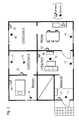
- FIG. 2is a layout drawing showing an example of the layout of sensors 11 to 18 and cameras 21 to 26 .
- a sensor 11 and a camera 21are installed in the entrance hall.
- the sensor 11detects the existence of human being in the entrance hall, while the camera 21 captures the image of the whole entrance hall area.
- sensors 12 and 13as well as a camera 22 are installed.
- the sensor 12detects the existence of human being in the center area of the room while the sensor 13 detects any existence of human being around the window of the living room, and the camera 22 captures the image of the whole room including the window area.
- a sensor 14 and a camera 23are installed in the kitchen.
- the sensor 14detects the existence of human being around the window of the kitchen, while the camera 23 captures the image of the whole kitchen area including the window.
- a sensor 15 and a camera 24are installed in the child's room A.
- the sensor 15detects any existence of human being around the window of the child's room A, while the camera 24 captures the image of the whole room including the window area.
- sensors 16 and 17 as well as a camera 25are installed in the child's room B.
- the sensor 16detects the existence of human being in the center area of the room while the sensor 17 detects any existence of human being around the window of the child's room B, and the camera 25 captures the image of the whole room including the window area.
- a sensor 18 and a camera 26are installed.
- the sensor 18detects the existence of human being around the window of the room, while the camera 26 captures the image of the whole bedroom area including the window.
- the sensors 11 to 18comprise, for example, infrared sensors of pyroelectric-type that detect any existence of human being within a certain area by receiving infrared radiation emitted from human bodies, and send detection signals that notify whether there are any human being detected or not to the controller 30 via the electric power lines L.
- Identification information for identifying each of the sensors 11 to 18are also allocated, and when the sensors 11 to 18 send detection signals, they send as well the identification information that is allocated to each of them to the controller 30 .
- the center server 40is located in a security company etc. that was commissioned to monitor the house by the resident of the house, meaning the user of the system, and places the images captured by any of the cameras 21 to 26 on a web page.
- the cameras 21 to 26have equal structure and function with each other, capture still images and send image data that indicates the content of the captured images to the controller 30 via the electric power lines L.
- FIG. 3is a perspective illustration of the camera 21 .
- the camera 21includes optical and electronic equipment for performing the above-mentioned functions, a case 20 d which is a nearly rectangular box made of molded resin that contains said equipment, a power cable 20 e that is lead out from inside of the case 20 d , and a plug 20 f that is fit at the end of the power cable 20 e opposite from the case 20 d.
- a protruding part 20 dais formed to protrude frontward, and the protruding part 20 da has an opening part 20 db that connects the inside and outside of the case 20 d .
- the protruding part 20 daalso has a translucent film 20 dc that transmits light and is fit to block the opening part 20 db.
- CCDCharge Coupled Device
- the camera 21is installed so that the backside of the case 20 d faces the wall, and is used by plugging in the plug 20 f to a power receptacle located inside of the house.
- FIG. 4is a block diagram of the optical and electronic equipment of the camera 21 .
- the camera 21is equipped with the lenses and the CCD, and includes an image capturing unit 20 a that generates the image data, an image processing unit 20 b that performs image processing such as compressing the image data, and a communication control unit 20 c that communicates with the controller 30 and controls the image capturing unit 20 a and the image processing unit 20 b according to the communication result.
- the cameras 22 to 26have the same structure as the camera 21 , which means each of them has an image capturing unit 20 a , an image processing unit 20 b and a communication control unit 20 c.
- the communication control unit 20 cWhen the communication control unit 20 c receives an image capturing direction signal that directs to capture an image from the controller 30 , it makes the image capturing unit 20 a to capture an image and generate image data, and makes the image processing unit 20 b to compress the image data after changing the image data to a prescribed size. For example, the communication control unit 20 c makes the image capturing unit 20 a to capture an image and to generate image data of 320 ⁇ 240 pixels, and then makes the image processing unit 20 b to change the image data to image data of 240 ⁇ 80 pixels and to compress the image data by JPEG (Joint Photographic Experts Group) format. The data size of the compressed image data differs according to the object of shooting.
- JPEGJoint Photographic Experts Group
- the communication control unit 20 csends a size notification signal that notifies the data size of the compressed image data to the controller 30 . And when the communication control unit 20 c receives a transmission direction signal, from the controller 30 , that directs to send the image data in said data size, the communication control unit 20 c sends the image data to the controller 30 . Meanwhile, when the communication control unit 20 c receives a compression transmission direction signal, from the controller 30 , that directs to compress the data size with a prescribed compression ratio before sending, the communication control unit 20 c makes the image processing unit 20 b compress the image data with the directed compression ratio, and sends the compressed image data to the controller 30 .
- the camera 21compresses the image data before sending, it can prevent the image quality to be lowered while shortening the time needed for transmission as well.
- the communication control unit 20 cdoes not send the image data as it is, but divides the image data when sending to the controller 30 .
- FIG. 5is a data structure diagram that illustrates image data being divided and transmitted.
- the communication control unit 20 cinstructs the image processing unit 20 b to divide the image data P 1 into one or more than one divided image data P 2 that has the data size of 131 bytes each, and a divided image data P 3 that has the data size of less than 131 bytes.
- the communication control unit 20 ccreates packets by adding, to each of the divided image data P 2 and P 3 , a header section p 1 , number information p 2 that indicates the number allocated to the divided image data P 2 and P 3 , date and time information p 3 that indicates the date and time that the image is captured, and data size information p 4 that indicates the data size of the image data P 1 before dividing, and then sends the plurality of packets that include the divided image data P 2 or the divided image data P 3 to the controller 30 .
- the controller 30that has obtained the plurality of packets is able to judge whether all the packets are obtained or not from the number indicated by the number information p 2 , the data size indicated by the data size information p 4 and the date and time indicated by the date and time information p 3 , all of which being included in each of the packets, and thus an accurate transmission of the image data P 1 becomes possible.
- the controller 30When the controller 30 receives a detection signal that notifies an existence of human being together with identification information from any of the sensors 11 to 18 , it directs a camera that is associated with the sensor to which the identification number is allocated to capture an image.
- FIG. 6is a perspective illustration of the controller 30 .
- the controller 30includes electronic equipment for performing the above-mentioned functions, a controller case 30 a which is a nearly rectangular box made of molded resin that contains said equipment, a power cable 30 b that is lead out from inside of the controller case 30 a , and a plug 30 c that is fit at the end of the power cable 30 b opposite from the controller case 30 a .
- the controller 30is installed so that the backside of the controller case 30 a faces the wall, and is used by plugging in the plug 30 c to a power receptacle located inside of the house.
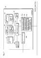
- FIG. 7is a block diagram of the electronic equipment included in the controller 30 .
- the controller 30includes an electric power line communication unit 31 that communicates with sensors 11 to 18 and cameras 21 to 26 via electric power lines L, a net communication unit 33 a that communicates with a center server 40 via the Internet 100 , a display unit 34 that displays characters and images according to input signals, an image memory unit 35 that memorizes image data P 1 , a linkage memory unit 36 which memorizes linkage information 36 d that indicates the association between the sensors 11 to 18 and the cameras 21 to 26 , a calculation unit 37 that calculates the compression ratio for directing any of the cameras 21 to 26 to compress image data P 1 , a main control unit 38 that controls the electric power line communication unit 31 , the net communication unit 33 a , the display unit 34 , the image memory unit 35 , the linkage memory unit 36 and the calculation unit 37 , as well as an operation unit 39 that is equipped with a plurality of operation buttons operated by the user and outputs operation signals that indicate directions according to the operation to the main control unit 38 .
- the electric power line communication unit 31includes an image requesting unit 31 c that directs any of the cameras 21 to 26 to capture images and requests image data P 1 , an image obtaining unit 31 b which obtains packets that include the image data P 1 or divided image data P 2 and P 3 from any of the cameras 21 to 26 , and a sensor reception unit 31 a that receives detection signals and identification information from any of the sensors 11 to 18 .
- FIG. 6Also as shown in FIG. 6, several openings that connect the inside and outside of the case are formed at the front side of the controller case 30 a .
- the display unit 34is located inside of the controller case 30 a so that the side that displays characters and images is exposed from one of the openings, while the operation unit 39 is located inside of the controller case 30 a so that the operation buttons are exposed from other openings.
- FIG. 8is a sequence diagram showing an example of an overall operation according to the present embodiment.
- Step S 100when the sensor 11 that is installed in the entrance hall detects human being (Step S 100 ), the sensor 11 sends a detection signal that notifies an existence of human being as well as its own identification information to the controller 30 (Step S 102 ).
- the main control unit 38 of the controller 30comprehends, based on the received result, that the sensor 11 has detected human being and refers to linkage information 36 d that is memorized in the linkage memory unit 36 (Step S 104 ).
- this linkage information 36 dthe sensor 11 is associated with the camera 21 .
- the main control unit 38 of the controller 30determines that a camera associated with the sensor 11 is the camera 21 (Step S 106 ). Then, the main control unit 38 makes the image requesting unit 31 c of the electric power line communication unit 31 to send an image capturing direction signal that directs the camera 21 to capture an image (Step S 108 ).
- the communication control unit 20 c of the camera 21receives the image capturing direction signal, it makes the image capturing unit 20 a to capture an image (Step S 110 ), and makes the image processing unit 20 b to change size and compress image data P 1 generated by the image capturing unit 20 a (Step S 112 ). Then, the communication control unit 20 c sends a size notification signal that notifies the controller 30 of the data size of the compressed image data P 1 (Step S 114 ).
- the main control unit 38 of the controller 30judges whether the image data P 1 generated by the camera 21 needs to be compressed further, based on the data size indicated by the size notification signal (Step S 116 ).
- the main control unit 38 of the controller 30judges that compression is not necessary because the data size is less than or equal to a prescribed size, it makes the image requesting unit 31 c of the electric power line communication unit 31 to send, to the camera 21 , a transmission direction signal that directs to send the image data P 1 without compressing (Step S 118 ).
- the main control unit 38 of the controller 30judges that compression is necessary because the data size is larger than a prescribed size, it makes the calculation unit 37 to calculate the compression ratio so that the data size becomes less than or equal to the prescribed size (Step S 120 ).
- the main control unit 38then makes the image requesting unit 31 c of the electric power line communication unit 31 to send, to the camera 21 , a compression transmission direction signal that directs to compress the image data by the calculated compression ratio and send the compressed image data P 1 (Step S 122 ).
- the communication control unit 20 c of the camera 21receives the compression transmission direction signal, it instructs the image processing unit 20 b to compress the image data P 1 by the compression ratio directed by the signal (Step S 124 ), and if necessary, makes the image processing unit 20 b to divide the compressed image data P 1 into a plurality of divided image data P 2 and P 3 (Step S 126 ). Then, the communication control unit 20 c sends the divided image data P 2 and P 3 that are made into packets to the controller 30 (Step S 128 ).
- the main control unit 38 of the controller 30obtains the plurality of packets via the image obtaining unit 31 b of the electric power line communication unit 31 , it combines the divided image data P 2 and P 3 that are included in each of the packets, reproduces the image data P 1 before dividing, and memorizes the image data P 1 in the image memory unit 35 (Step S 130 ).
- the main control unit 38determines that all the packets are not obtained by the image obtaining unit 31 b , by checking the number indicated by number information p 2 and the data size indicated by the data size information p 4 that are included in each of the packets, the main control unit 38 identifies the missing packet. And the main control unit 38 makes the image requesting unit 31 c of the electric power line communication unit 31 to specify, to the camera 21 , the number of the number information p 2 included in the missing packet and request to send the packet. Since the communication control unit 20 c of the camera 21 sends the packet according to the request, the image data P 1 can be sent accurately.
- the main control unit 38 of the controller 30sends the reproduced image data P 1 to the display unit 34 and makes the image display unit 34 to display the image captured by the camera 21 (Step S 132 ).
- the main control unit 38also makes the net communication unit 33 a to send the image data P 1 to the center server 40 via the Internet 100 (Step S 134 ).
- the center server 40When the center server 40 obtains the image data P 1 , it places an image based on the image data P 1 onto a certain web page (Step S 136 ).
- the center server 40sends data for displaying the web page to the cellular phone 50 (Step S 140 ).
- the cellular phone 50displays the web page that includes the image captured by the camera 21 onto a display unit, which includes LCD (Liquid crystal display), that is equipped to the phone (Step S 142 ).
- cameras 21 to 26capture images of certain locations within a house when any intruder breaks into the house, and the captured images are sent to the center server 40 .
- the security company that owns the center server 40can easily figure out the condition of the house, while by placing the image onto a web page, the resident of the house is able to figure out the condition of the house by using the cellular phone 50 from somewhere outside and viewing the image through the Internet 100 .
- the setting of the relationships between sensors 11 to 18 and cameras 21 to 26are made to be variable.
- the linkage information 36 dthat is memorized in the linkage memory unit 36 , there is a plurality of modes categorized according to the level and condition of monitoring, and the linkages between the sensors 11 to 18 and the cameras 21 to 26 are registered according to each mode.
- the main control unit 38Based on an operation signal outputted from the operating unit 39 as a result of an operation made by the user to the operation unit 39 , the main control unit 38 selects one of the plurality of modes in the linkage information 36 d and directs a camera that is associated with the selected mode to capture an image.
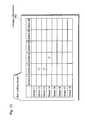
- FIG. 9is an explanatory diagram for explaining the content included in linkage information 36 d.
- Linkage information 36 dmay have, for example, five different modes that are “Not home mode”, “At home mode”, “User setting mode 1”, “User setting mode 2”, and “User setting mode 3”.
- “Not home mode”is a mode suitable when sufficient monitoring is necessary such as the case when all the residents of the house are going out, and in this “Not home mode”, each of the sensors 11 to 18 are associated with all of the cameras 21 to 26 as shown by the circles in FIG. 9 . So when the user selects the “Not home mode” according to the necessary level of monitoring by operating the operation buttons of the operation unit 39 of the controller 30 , the main control unit 38 selects the “Not home mode” out of five different modes, and when any of the sensors 11 to 18 detects human being, the main control unit 38 directs all of the cameras 21 to 26 to capture images.
- “At home mode”is a mode suitable when monitoring is not necessary such as the case when the resident of the house is at home, and in this “At home mode”, the sensors 11 to 18 are not associated with any of the cameras. Accordingly, when the user selects the “At home mode” according to the necessary level of monitoring by operating the operation buttons of the operation unit 39 of the controller 30 , the main control unit 38 selects the “At home mode” out of five different modes, and does not direct the cameras 21 to 26 to capture images even when any of the sensors 11 to 18 detects human being.
- “User setting mode 1”, “User setting mode 2” and “User setting mode 3”are the modes to which the relationships are set by the user.
- FIG. 10is an explanatory diagram for explaining relationships between sensors 11 to 18 and cameras 21 to 26 in the “User setting mode 1”.
- the “User setting mode 1”is a mode in which the sensors 11 to 18 and the cameras 21 to 26 are linked so that when the sensor installed in each room detects human being, the camera installed in the same room is made to capture an image.
- the sensor 11is linked with the camera 21 , the sensors 12 and 13 with the camera 22 , the sensor 14 with the camera 23 , the sensor 15 with the camera 24 , the sensors 16 and 17 with the camera 25 and the sensor 18 is linked with the camera 26 .
- the main control unit 38 of the controller 30selects the “User setting mode 1” out of five different modes, and for example, makes the camera 21 to capture the image of the entrance hall if the sensor 11 that is located in the entrance hall detects human being, and makes the camera 25 to capture the image of the child's room B if the sensor 16 that is located in the child's room B detects human being.
- FIG. 11is an explanatory diagram for explaining relationships between sensors 11 to 18 and cameras 21 to 26 in the “User setting mode 2”.
- the “User setting mode 2”is a mode in which the sensors 11 to 18 and the cameras 21 to 26 are linked so that when any of the sensors installed in each room other than the child's room A and the child's room B detects human being, the cameras installed in the same room as the sensor as well as those installed in the child's room A and the child's room B are made to capture images, and when the sensors installed in the child's room A and the child's room B detect human being, none of the cameras is made to capture image.
- the sensor 11is linked with the cameras 21 , 24 and 25 , the sensors 12 and 13 with the cameras 22 , 24 and 25 , the sensor 14 with the cameras 23 to 25 , the sensor 18 with the cameras 24 to 26 , and the sensors 15 , 16 and 17 are not linked with any of the cameras.
- the userselects the “User setting mode 2” according to the level and condition of monitoring necessary in such a case. Then, the main control unit 38 of the controller 30 selects the “User setting mode 2” out of five different modes, and directs the cameras 21 , 24 and 25 to capture the images of the entrance hall as well as the child's room A and the child's room B if the sensor 11 detects human being in the entrance hall, and makes the cameras 22 , 24 and 25 to capture the images of the living room as well as the child's room A and the Child's room B if the sensor 12 detects human being in the living room.
- FIG. 12is an explanatory diagram for explaining relationships between sensors 11 to 18 and cameras 21 to 26 in the “User setting mode 3”.
- the “User setting mode 3”is a mode in which the sensors 11 to 18 and the cameras 21 to 26 are linked so that when the sensors installed in the entrance hall, the living room or the kitchen detect human being, the cameras installed in the respective rooms are made to capture images.
- the sensor 11is linked with the camera 21 , the sensors 12 and 13 with the camera 22 , the sensor 14 with the camera 23 , and the sensors 15 , 16 , 17 and 18 are not linked with any of the cameras.
- the userselects the “User setting mode 3” according to the level and condition of monitoring necessary in such a case. Then, the main control unit 38 of the controller 30 selects the “User setting mode 3” out of five different modes, and directs the camera 21 to capture the image of the entrance hall if the sensor 11 detects human being in the entrance hall, and makes the camera 22 to capture the image of the living room if the sensor 12 detects human being in the living room.
- the main control unit 38 of the controller 30makes display unit 34 to display a screen that inquires whether the user desires to change or confirm the mode setting, or to change or confirm the setting of relationships between sensors and cameras (hereinafter referred to as “linkage setting”) in each mode.
- FIG. 13is a screen display diagram that shows an example of said screen.
- buttons B 1 and B 2which reads “Linkage setting” that is for updating or confirming linkage setting are displayed.
- the userdesires to change or confirm mode setting, he/she operates the operation buttons of the operation unit 39 that are marked with arrows so that the button B 1 is highlighted, and then operates the operation button of the operation unit 39 that is marked as “OK” to select the button B 1 .
- the main control unit 38 of the controller 30makes the display unit 34 to display the currently selected mode as well as a screen that inquires whether to change the mode or not.
- FIG. 14is a screen display diagram that shows an example of a screen of the display unit 34 for displaying the mode currently selected by the controller 30 .
- “At home mode”is displayed on the display unit 34 as a currently selected mode. Also on the display unit 34 are a button B 3 which reads “OK” for directing that the current setting is not changed, and a button B 4 which reads “Update” for directing to update the current setting.
- the useris able to confirm the currently selected mode by viewing the screen displayed as mentioned above, and be able to recognize that the monitoring level is set to be the lowest when “At home mode” is displayed as explained above.
- the userdesires to change the mode setting, the user operates the operation buttons of the operation unit 39 as has been explained, makes the button B 4 highlighted and selects it.
- the main control unit 38 of the controller 30makes the display unit 34 to display a screen for selecting mode.
- FIG. 15is a screen display diagram that shows an example of the above-mentioned selection screen.
- buttons which indicate modes that can be selectedare displayed on the display unit 34 , which are: a button B 5 that reads “At home mode”, a button B 6 that reads “Not home mode”, a button B 7 that reads “User setting mode 1”, a button B 8 that reads “User setting mode 2” and a button B 9 that reads “User setting mode 3”.
- the “User setting mode 1”is selected for the main control unit 38 of the controller 30 , and when any of the sensors 11 to 18 detects human being, the main control unit 38 directs the cameras 21 to 26 that are linked with these sensors by the “User setting mode 1” to capture images.
- the useris able to change as well as increase or decrease the locations of capturing images according to the level and condition of monitoring by operating the operation unit 39 of the controller 30 .
- the userdesires to change the linkage setting of the “User setting mode 1”, which is the currently selected mode in this case, the user selects the button B 2 which reads “Linkage setting” in the screen shown in FIG. 13 .
- the main control unit 38 of the controller 30makes the display unit 34 to display a screen that allows to change the linkage setting.
- FIG. 16is a screen display diagram that shows an example of a screen that allows to change linkage settings.
- the upper part of the display unit 34displays the layout of the sensors 11 to 18 and cameras 21 to 26 to show their locations, and the bottom part of the display unit 34 displays a chart for selecting cameras that are associated with each of the sensors 11 to 18 .
- the chartconsists of eight sheets Se 1 to Se 8 that correspond to each of the sensors, and in each of the sheets Se 1 to Se 8 , cameras that are linked with each of the sensors are indicated.
- the sheet Se 1shows the cameras that are linked with the sensor 11
- the sheet Se 2shows the cameras that are linked with the sensor 12 .
- the names of cameras 21 to 26are shown, and on the right of each camera names, check boxes Bo for showing check marks that indicate whether each camera is associated with the sensor or not are displayed. For example, if the check box Bo next to the name “Camera 21 ” has a check mark in it, the sheet Se 1 indicates that the sensor 11 is linked with the camera 21 .
- the userdesires to change the linkage setting, the user selects the sheet that indicates the sensor subject to changing by operating the operation unit 39 of the controller 30 , while referring to the layout displayed on the upper part of the display unit 34 at the same time. Then the user can add a check mark to the check box Bo next to the camera that is to be newly linked with the sensor, or delete the check mark in the check box Bo next to the camera that is to be removed from the linkage. In this way, the user can direct the controller 30 to change the linkage settings.
- the association between the sensors and camerascan be changed according to the user's choice by operating the controller 30 .
- FIG. 17is a perspective illustration of a camera according to the variation.
- the camera 210 shown in FIG. 17has the basic structure and function of the cameras 21 to 26 , and also is able to make the controller 30 to change the mode settings categorized according to the level and condition of monitoring by operating a push-button switch 201 b that is located at the front side of the camera.
- This variation of the home security systemincludes the camera 210 instead of any or all of the cameras 21 to 26 used in the home security system according to the already mentioned embodiment.
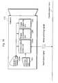
- FIG. 18is a block diagram showing an internal structure of the camera 210 .
- the camera 210includes an image capturing unit 20 a , an image processing unit 20 b , a communication control unit 200 c , a camera operation unit 203 equipped with the push-button switch 201 b , and a camera display unit 202 a that comprises, for example, light emitting diode.
- the case 200 d of the camera 210is, as shown in FIG. 17 and similar to the case 20 d of the cameras 21 to 26 , shaped as a nearly rectangular box.
- a protruding part 20 da and an opening part 20 dbare also formed.
- a window 202 for exposing the camera display unit 202 ais also formed.
- the camera operation unit 203outputs a signal according to the operation of the push-button switch 201 b to the communication control unit 200 c , and every time the communication control unit 200 c receives the signal, it outputs a mode switching signal that directs to switch the mode to the controller 30 via the electric power lines L.
- the main control unit 38 of the controller 30obtains the mode switching signal via the electric power line communication unit 31 , and switches the modes that are set in the order of “Not home mode” ⁇ “At home mode” ⁇ “User setting mode 1” ⁇ “User setting mode 2” ⁇ “User setting mode 3”. This means, when the currently selected mode is the “Not home mode”, the main control unit 38 changes the mode to “At home mode” by receiving a mode switching signal, and if it receives another mode switching signal, the main control unit 38 changes the mode to “User setting mode 1”.
- the main control unit 38makes the electric power line communication unit 31 to send, via the electric power lines L, a notification signal that notifies all of cameras 210 that are connected with the electric power lines L of the changed mode.
- the communication control unit 200 c of the camera 210obtains a notification signal from the controller 30 , it specifies the changed mode based on the notification signal and makes the camera display unit 202 a to light up according the changed mode.
- the communication control unit 200 cmakes the camera display unit 202 a to light up.
- the camera display unit 202 ais made to blink in a long cycle, or if it was judged that the mode setting was changed to “User setting mode 2”, then the camera display unit 202 a is made to blink in a short cycle. If the camera display unit 202 a is able to emit multiple colors, the camera display unit 202 a may also be made to emit different colors of light according to the changed modes.
- the usercan easily change the mode setting, not by operating the controller 30 that is installed in the house, but by operating the push-button switch 201 b of the camera operation unit 203 in the camera 210 that is near the user.
- the usercan also figure out the currently selected mode quite easily by viewing the camera display unit 202 a.
- FIG. 19is a block diagram of a sensor according to the variation.
- the sensor 110 shown in FIG. 19has the basic structure and function of the sensors 11 to 18 , and also is a sensor that displays the currently selected mode.
- This variation of the home security systemincludes the sensor 110 instead of any or all of the sensors 11 to 18 used in the home security system according to the already mentioned embodiment.
- the sensor 110includes a sensor body 110 a that has similar functions as the sensors 11 to 18 and detects the existence of human being, as well as a sensor display unit 110 b that comprises, for example, light emitting diode, that emits light according to the control from the sensor body 110 a.
- the main control unit 38 of the controller 30 in this variationoutputs a notification signal that notifies all of sensors 110 of the changed mode setting every time it changes the mode setting that are categorized according to the level and condition of monitoring.
- the sensor body 110 a of the sensor 110obtains the notification signal from the controller 30 , it makes the sensor display unit 110 b to light up according to the changed mode. This means, similar to the camera 210 , the sensor display unit 110 b displays the currently selected mode by blinking etc.
- the usercan easily figure out the currently selected mode and the level and condition of monitoring, not by operating the controller 30 that is installed in the house, but by viewing the sensor display unit 110 b of the sensor 110 that is near the user.
- the main control unit 38 of the controller 30sends a notification signal that notifies all of cameras 210 and sensors 110 of the changed mode setting every time it changes the mode setting.
- the usercan easily change the mode setting, not by operating the controller 30 that is installed in the house, but by operating the camera operation unit 203 of the camera 210 that is near the user.
- the usercan also figure out the currently selected mode more easily by viewing the camera display unit 202 a or the sensor display unit 110 b.
- the cellular phone 50was used only to display the images that are placed on the web page by the center server 40 , but the cellular phone 50 may also be used to display and change mode settings and linkage settings.
- the center server 40communicates with the controller 30 and makes the screens for mode setting and linkage setting as shown in FIGS. 13 to 16 to be placed on the web page. Then, the cellular phone 50 displays said web page onto its own display unit by accessing the center server 40 .
- the usercan easily confirm the mode setting and the linkage setting from a place where he/she has gone by using the cellular phone 50 .
- the cellular phone 50carries out the operation similar to the operation unit 39 of the controller 30 according to the operation made with its own dial buttons, and sends, to the center server 40 via the Internet 100 , an operation signal that selects the buttons B 1 to B 9 etc. on the screen as shown in FIGS. 13 to 16 that are displayed on the web page. Then, the center server 40 sends the operation signal from the cellular phone 50 to the controller 30 , and makes the main control unit 38 of the controller 30 to change the mode settings and linkage settings.
- the usercan easily change the mode settings as well as linkage settings by using the cellular phone 50 from a place where he/she has gone.
- cameras 21 to 26 and 210it is also possible to have cameras 21 to 26 and 210 to include memory units that memorize image data P 1 .
- the communication control unit 20 c or 200 c of the cameras 21 to 26 or 210makes the information which indicates the date and time that the image data P 1 is generated to be included in the image data P 1 , and then makes the memory unit to memorize the image data P 1 .
- the main control unit 38 of the controller 30receives, from the operation unit 39 , an operation signal that specifies a date and time and directs to display the images captured on the date and time
- the main control unit 38makes the image requesting unit 31 c of the electric power light communication unit 31 to request, to the cameras 21 to 26 and 210 , to send the image data P 1 which includes the information that indicates the specified date and time.
- the communication control unit 20 c or 200 c of the cameras 21 to 26 or 210selects, from the memory unit, image data P 1 that corresponds to the request from the controller 30 and sends the image data P 1 to the controller 30 .
- the cameras 21 to 26 and 210 , the sensors 11 to 18 and 110 , and the controller 30transmit signals between each other via electric power lines L in the present embodiment and its variations, but the transmission can also be made, other than the electric power lines L, via dedicated communication cables etc.
- the currently selected mode and the relationships between sensors and cameras that are set according to each modeare displayed by the display unit 34 only by operating the operation unit 39 of the controller 30 in the present embodiment and its variations, but it can also be made to display the information all the time regardless of the operation of the operation unit 39 . In such case, the user can easily confirm the current settings without operating the operation unit 39 .
Landscapes
- Engineering & Computer Science (AREA)
- Physics & Mathematics (AREA)
- General Physics & Mathematics (AREA)
- Multimedia (AREA)
- Human Computer Interaction (AREA)
- Library & Information Science (AREA)
- Signal Processing (AREA)
- Business, Economics & Management (AREA)
- Emergency Management (AREA)
- Alarm Systems (AREA)
- Closed-Circuit Television Systems (AREA)
- Telephonic Communication Services (AREA)
Abstract
Description
Claims (42)
Applications Claiming Priority (2)
| Application Number | Priority Date | Filing Date | Title |
|---|---|---|---|
| JP2001-363317 | 2001-11-28 | ||
| JP2001363317 | 2001-11-28 |
Publications (2)
| Publication Number | Publication Date |
|---|---|
| US20030098789A1 US20030098789A1 (en) | 2003-05-29 |
| US6759957B2true US6759957B2 (en) | 2004-07-06 |
Family
ID=19173679
Family Applications (1)
| Application Number | Title | Priority Date | Filing Date |
|---|---|---|---|
| US10/300,850Expired - LifetimeUS6759957B2 (en) | 2001-11-28 | 2002-11-21 | Home security system |
Country Status (5)
| Country | Link |
|---|---|
| US (1) | US6759957B2 (en) |
| EP (1) | EP1316933B1 (en) |
| KR (1) | KR20030043778A (en) |
| CN (1) | CN100409578C (en) |
| DE (1) | DE60213746T2 (en) |
Cited By (44)
| Publication number | Priority date | Publication date | Assignee | Title |
|---|---|---|---|---|
| US20050007999A1 (en)* | 2003-06-25 | 2005-01-13 | Gary Becker | Universal emergency number ELIN based on network address ranges |
| US20050128072A1 (en)* | 2003-12-16 | 2005-06-16 | Li Shih H. | Security system for a building |
| US20050151848A1 (en)* | 2004-01-09 | 2005-07-14 | Jean Wang | Image transmitter |
| US20050270143A1 (en)* | 2004-06-02 | 2005-12-08 | Inventec Appliances Corporation | Surveillance apparatus integrated with mobile phone |
| US20060001537A1 (en)* | 2003-11-20 | 2006-01-05 | Blake Wilbert L | System and method for remote access to security event information |
| US20060044136A1 (en)* | 2004-08-26 | 2006-03-02 | Dsfe Security Systems International, Inc. | Method and device for intrusion detection using an optical continuity system |
| US20060120517A1 (en)* | 2004-03-05 | 2006-06-08 | Avaya Technology Corp. | Advanced port-based E911 strategy for IP telephony |
| US20060158310A1 (en)* | 2005-01-20 | 2006-07-20 | Avaya Technology Corp. | Mobile devices including RFID tag readers |
| US20060235765A1 (en)* | 2005-04-15 | 2006-10-19 | David Clifford R | Interactive Image Activation and Distribution System and Associated Methods |
| US20070047641A1 (en)* | 2005-08-26 | 2007-03-01 | James Bellinson | Self-contained security system |
| US20070063840A1 (en)* | 2005-09-22 | 2007-03-22 | Keith Jentoft | Security monitoring arrangement and method using a common field of view |
| US20070066311A1 (en)* | 2005-09-22 | 2007-03-22 | Jean-Michel Reibel | Spread spectrum wireless communication and monitoring arrangement and method |
| US20070094720A1 (en)* | 2005-09-01 | 2007-04-26 | Charles Galambos | Security system |
| US20070182543A1 (en)* | 2006-02-04 | 2007-08-09 | Hongyue Luo | Intelligent Home Security System |
| US20070188798A1 (en)* | 2005-04-15 | 2007-08-16 | David Clifford R | Interactive Image Activation and Distribution System and Associated Methods |
| USD555528S1 (en) | 2006-03-24 | 2007-11-20 | Rsialarm, Inc. | Mountable security detector |
| US7339607B2 (en)* | 2005-03-25 | 2008-03-04 | Yongyouth Damabhorn | Security camera and monitor system activated by motion sensor and body heat sensor for homes or offices |
| US20080158336A1 (en)* | 2006-10-11 | 2008-07-03 | Richard Benson | Real time video streaming to video enabled communication device, with server based processing and optional control |
| US20080239409A1 (en)* | 2007-03-27 | 2008-10-02 | David Clifford R | Interactive Image Activation and Distribution System and Associated Methods |
| US20080252730A1 (en)* | 2007-04-10 | 2008-10-16 | Winfield Vision Development (Holding) Ltd. | Infrared sensitive security lighting system |
| US20090179988A1 (en)* | 2005-09-22 | 2009-07-16 | Jean-Michel Reibel | Integrated motion-image monitoring device with solar capacity |
| US20090200374A1 (en)* | 2008-02-07 | 2009-08-13 | Jentoft Keith A | Method and device for arming and disarming status in a facility monitoring system |
| US20090243834A1 (en)* | 2008-03-27 | 2009-10-01 | At&T Mobility Ii Llc | Systems And Methods For Controlling A Secruity System Via A Mobile Device |
| US7835343B1 (en) | 2006-03-24 | 2010-11-16 | Rsi Video Technologies, Inc. | Calculating transmission anticipation time using dwell and blank time in spread spectrum communications for security systems |
| US8463654B1 (en) | 2009-05-01 | 2013-06-11 | Clifford R. David | Tour site image capture and marketing system and associated methods |
| US20140005809A1 (en)* | 2012-06-27 | 2014-01-02 | Ubiquiti Networks, Inc. | Method and apparatus for configuring and controlling interfacing devices |
| USD711272S1 (en) | 2013-04-09 | 2014-08-19 | Rsi Video Technologies, Inc. | Mountable security detector |
| US8860568B1 (en) | 2012-12-17 | 2014-10-14 | Aaron M. Baker | Home floor safe security system |
| US9172605B2 (en) | 2014-03-07 | 2015-10-27 | Ubiquiti Networks, Inc. | Cloud device identification and authentication |
| US9189934B2 (en) | 2005-09-22 | 2015-11-17 | Rsi Video Technologies, Inc. | Security monitoring with programmable mapping |
| US9191037B2 (en) | 2013-10-11 | 2015-11-17 | Ubiquiti Networks, Inc. | Wireless radio system optimization by persistent spectrum analysis |
| US9214032B2 (en) | 2005-04-15 | 2015-12-15 | Freeze Frame, Llc | Interactive guest image capture using video wall/floor/ceiling displays for selections of background scenes, and selection/distribution of customized |
| US9270841B2 (en) | 2005-04-15 | 2016-02-23 | Freeze Frame, Llc | Interactive image capture, marketing and distribution |
| US9270840B2 (en) | 2011-08-24 | 2016-02-23 | Freeze Frame, Llc | Site image capture and marketing system and associated methods |
| US9293817B2 (en) | 2013-02-08 | 2016-03-22 | Ubiquiti Networks, Inc. | Stacked array antennas for high-speed wireless communication |
| US9325516B2 (en) | 2014-03-07 | 2016-04-26 | Ubiquiti Networks, Inc. | Power receptacle wireless access point devices for networked living and work spaces |
| US9368870B2 (en) | 2014-03-17 | 2016-06-14 | Ubiquiti Networks, Inc. | Methods of operating an access point using a plurality of directional beams |
| US9472067B1 (en) | 2013-07-23 | 2016-10-18 | Rsi Video Technologies, Inc. | Security devices and related features |
| US9490533B2 (en) | 2013-02-04 | 2016-11-08 | Ubiquiti Networks, Inc. | Dual receiver/transmitter radio devices with choke |
| US9495845B1 (en) | 2012-10-02 | 2016-11-15 | Rsi Video Technologies, Inc. | Control panel for security monitoring system providing cell-system upgrades |
| US9496620B2 (en) | 2013-02-04 | 2016-11-15 | Ubiquiti Networks, Inc. | Radio system for long-range high-speed wireless communication |
| US9543635B2 (en) | 2013-02-04 | 2017-01-10 | Ubiquiti Networks, Inc. | Operation of radio devices for long-range high-speed wireless communication |
| US9912034B2 (en) | 2014-04-01 | 2018-03-06 | Ubiquiti Networks, Inc. | Antenna assembly |
| US10834335B2 (en) | 2005-04-15 | 2020-11-10 | Freeze Frame, Llc | Interactive guest image capture using video wall/floor/ceiling displays for selections of background scenes, and selection/distribution of customized souvenir portfolios including merged images/sound |
Families Citing this family (48)
| Publication number | Priority date | Publication date | Assignee | Title |
|---|---|---|---|---|
| US6714977B1 (en)* | 1999-10-27 | 2004-03-30 | Netbotz, Inc. | Method and system for monitoring computer networks and equipment |
| US7392309B2 (en)* | 1999-10-27 | 2008-06-24 | American Power Conversion Corporation | Network appliance management |
| US7330886B2 (en) | 1999-10-27 | 2008-02-12 | American Power Conversion Corporation | Network appliance management |
| JP4146592B2 (en)* | 1999-11-12 | 2008-09-10 | 株式会社日立製作所 | Adaptive communication method and equipment constituting distributed system |
| US8271626B2 (en) | 2001-01-26 | 2012-09-18 | American Power Conversion Corporation | Methods for displaying physical network topology and environmental status by location, organization, or responsible party |
| EP1360796B1 (en) | 2001-01-26 | 2009-12-23 | American Power Conversion Corporation | Method and system for a set of network appliances which can be connected to provide enhanced collaboration, scalability, and reliability |
| CN101072364B (en) | 2001-09-07 | 2012-05-09 | 英特图形软件技术公司 | Image stabilization using color matching |
| WO2003094031A1 (en) | 2002-05-03 | 2003-11-13 | Netbotz, Inc. | Method and apparatus for collecting and displaying network device information |
| WO2004090679A2 (en) | 2003-04-14 | 2004-10-21 | Netbotz, Inc. | Environmental monitoring device |
| US7542963B2 (en)* | 2003-04-14 | 2009-06-02 | American Power Conversion Corporation | Method and system for journaling and accessing sensor and configuration data |
| DE602004024296D1 (en)* | 2003-04-14 | 2010-01-07 | American Power Conv Corp | EXPANDABLE SENSOR MONITORING, WARNING PROCESSING AND NOTIFICATION SYSTEM AND METHOD |
| US8566292B2 (en) | 2003-04-14 | 2013-10-22 | Schneider Electric It Corporation | Method and system for journaling and accessing sensor and configuration data |
| US7068166B2 (en)* | 2003-06-17 | 2006-06-27 | Sanki Eng. Co. Ltd. | Break-in detection system |
| DE20311245U1 (en)* | 2003-07-21 | 2003-09-18 | Everspring Industry Co. Ltd., Kweishan, Taoyuan | Multiple detection device |
| US7627651B2 (en) | 2003-10-27 | 2009-12-01 | American Power Conversion Corporation | System and method for network device communication |
| PL1685543T3 (en) | 2003-11-18 | 2009-07-31 | Intergraph Software Tech Company | Digital video surveillance |
| EP1564700A1 (en)* | 2004-02-11 | 2005-08-17 | Sensormatic Electronics Corporation | System and method for remote access to security event information |
| US7486183B2 (en)* | 2004-05-24 | 2009-02-03 | Eaton Corporation | Home system and method for sending and displaying digital images |
| WO2006049501A2 (en)* | 2004-11-01 | 2006-05-11 | Ultrawaves Design Holding B.V. | Flexible surveillance network system |
| US8145748B2 (en)* | 2004-12-13 | 2012-03-27 | American Power Conversion Corporation | Remote monitoring system |
| US7711814B1 (en) | 2004-12-13 | 2010-05-04 | American Power Conversion Corporation | Method and system for remote monitoring of a power supply device with user registration capability |
| US8107625B2 (en)* | 2005-03-31 | 2012-01-31 | Avaya Inc. | IP phone intruder security monitoring system |
| ITMI20051513A1 (en)* | 2005-08-02 | 2007-02-03 | S & A S R L | VIDEO MONITORING DEVICE FOR HOUSES AND ENVIRONMENTS AT RISK |
| CA2628392A1 (en) | 2005-11-03 | 2007-05-18 | Barry Stuecker | Security system |
| FR2898718B1 (en)* | 2006-03-15 | 2009-11-27 | Francois Leroux | CONTROL OF REMOTE SITES BY WIRELESS CONNECTIONS |
| EP1901254A1 (en)* | 2006-09-15 | 2008-03-19 | Siemens Schweiz AG | Verification of an alarm triggered by a hazard detector |
| US20090138313A1 (en) | 2007-05-15 | 2009-05-28 | American Power Conversion Corporation | Methods and systems for managing facility power and cooling |
| JP5265141B2 (en)* | 2007-06-15 | 2013-08-14 | オリンパス株式会社 | Portable electronic device, program and information storage medium |
| JP2008310680A (en)* | 2007-06-15 | 2008-12-25 | Olympus Corp | Control system, program, and information storage medium |
| JP5152967B2 (en) | 2007-10-12 | 2013-02-27 | パナソニック株式会社 | COMMUNICATION METHOD, COMMUNICATION DEVICE, AND COMMUNICATION SYSTEM, |
| US20090195382A1 (en)* | 2008-01-31 | 2009-08-06 | Sensormatic Electronics Corporation | Video sensor and alarm system and method with object and event classification |
| JP2011061665A (en)* | 2009-09-14 | 2011-03-24 | Ricoh Co Ltd | Image processor, information processor, image distribution system, method, and recording medium |
| US20120001755A1 (en)* | 2010-07-02 | 2012-01-05 | Richard Paul Conrady | Virtual Presence after Security Event Detection |
| JP2012249117A (en)* | 2011-05-30 | 2012-12-13 | Hitachi Ltd | Monitoring camera system |
| US8990536B2 (en) | 2011-06-01 | 2015-03-24 | Schneider Electric It Corporation | Systems and methods for journaling and executing device control instructions |
| US20130063592A1 (en)* | 2011-09-08 | 2013-03-14 | Scott Michael Kingsley | Method and system for associating devices with a coverage area for a camera |
| CN104137105B (en) | 2011-12-22 | 2017-07-11 | 施耐德电气It公司 | Analysis of the Effect of Transient Events on Temperature in Data Centers |
| US20140192188A1 (en)* | 2012-11-21 | 2014-07-10 | Technology Advancement Group, Inc. | Device and method for enhancing covert operations in hostile environments by reducing bandwidth and power requirements |
| CA2833112A1 (en)* | 2012-12-18 | 2014-06-18 | Kikuo Kaga | Construction image data recording system and data recording unit adapted to be embedded in a structure |
| TW201426673A (en)* | 2012-12-26 | 2014-07-01 | Hon Hai Prec Ind Co Ltd | Remote directing system and remote directing terminal system |
| US10515398B2 (en)* | 2015-02-12 | 2019-12-24 | At&T Mobility Ii Llc | System, method, and memory device for personalized vacations |
| US9911318B2 (en) | 2015-03-27 | 2018-03-06 | Google Llc | Configuring a smart home controller |
| CN104992518B (en)* | 2015-07-31 | 2018-02-16 | 深圳市欣横纵技术股份有限公司 | A kind of intelligent control command dispatching system applied to military project place |
| CN107221133B (en) | 2016-03-22 | 2018-12-11 | 杭州海康威视数字技术股份有限公司 | A kind of area monitoring alarm system and alarm method |
| CN105928504B (en)* | 2016-04-14 | 2018-03-20 | 北京小米移动软件有限公司 | Barrier localization method, apparatus and system |
| WO2017195286A1 (en)* | 2016-05-11 | 2017-11-16 | 三菱電機株式会社 | Air conditioning visualization system |
| KR102369805B1 (en)* | 2017-08-23 | 2022-03-03 | 한화테크윈 주식회사 | Method and apparatus for determining camera operation mode |
| JP7001410B2 (en)* | 2017-09-27 | 2022-02-03 | 株式会社キーエンス | Auxiliary unit for sensor unit |
Citations (12)
| Publication number | Priority date | Publication date | Assignee | Title |
|---|---|---|---|---|
| US4567557A (en)* | 1983-02-23 | 1986-01-28 | Burns Martin J | Building intelligence system |
| GB2264802A (en) | 1992-03-05 | 1993-09-08 | Fenmill Limited | Signal communication systems |
| DE4229257A1 (en) | 1992-09-02 | 1994-03-03 | Thomas Moore | Security surveillance system with alarm and image recording functions - providing undetected recording or obvious recording with deterrent effect under control of programmable central unit |
| US5459450A (en)* | 1992-02-20 | 1995-10-17 | Beghelli S.R.L. | Presence-detecting system |
| US5657076A (en)* | 1993-01-12 | 1997-08-12 | Tapp; Hollis M. | Security and surveillance system |
| JPH10271572A (en) | 1997-03-25 | 1998-10-09 | Nissho Seisakusho:Kk | Automatic metering system |
| GB2329541A (en) | 1997-09-17 | 1999-03-24 | Sony Uk Ltd | Highlighting view from controlled security camera |
| US5956081A (en)* | 1996-10-23 | 1999-09-21 | Katz; Barry | Surveillance system having graphic video integration controller and full motion video switcher |
| US5982418A (en)* | 1996-04-22 | 1999-11-09 | Sensormatic Electronics Corporation | Distributed video data storage in video surveillance system |
| EP0971540A1 (en) | 1991-05-13 | 2000-01-12 | Interactive Pictures Inc., (previously Omniview Inc) | Omniview motionless camera orientation system |
| JP2000091962A (en) | 1998-09-11 | 2000-03-31 | Ntt Power & Building Facilities Inc | Video monitor system utilizing power line for communication line and video transmitter |
| WO2001026280A1 (en) | 1999-10-07 | 2001-04-12 | G.Mate, Inc. | Security system and method using mobile communication network |
Family Cites Families (5)
| Publication number | Priority date | Publication date | Assignee | Title |
|---|---|---|---|---|
| JPH11328558A (en)* | 1998-05-19 | 1999-11-30 | Nec Telecom Syst Ltd | Guard terminal device |
| CN1256471A (en)* | 1999-04-16 | 2000-06-14 | 四川长虹电器股份有限公司 | TV picture album data making method |
| CN1125420C (en)* | 1999-04-30 | 2003-10-22 | 北京华讯和达数据科技有限公司 | Wire and wireless integrated safety alarm system |
| KR20010008215A (en)* | 2000-11-16 | 2001-02-05 | 김명근 | Real time moving picture remote guard controling system and method and interface device |
| CN1521698A (en)* | 2003-01-30 | 2004-08-18 | ���µ�����ҵ��ʽ���� | Household security system |
- 2002
- 2002-11-14DEDE60213746Tpatent/DE60213746T2/ennot_activeExpired - Lifetime
- 2002-11-14EPEP02025542Apatent/EP1316933B1/ennot_activeExpired - Lifetime
- 2002-11-21USUS10/300,850patent/US6759957B2/ennot_activeExpired - Lifetime
- 2002-11-28KRKR1020020074915Apatent/KR20030043778A/ennot_activeWithdrawn
- 2002-11-28CNCNB021543089Apatent/CN100409578C/ennot_activeExpired - Fee Related
Patent Citations (12)
| Publication number | Priority date | Publication date | Assignee | Title |
|---|---|---|---|---|
| US4567557A (en)* | 1983-02-23 | 1986-01-28 | Burns Martin J | Building intelligence system |
| EP0971540A1 (en) | 1991-05-13 | 2000-01-12 | Interactive Pictures Inc., (previously Omniview Inc) | Omniview motionless camera orientation system |
| US5459450A (en)* | 1992-02-20 | 1995-10-17 | Beghelli S.R.L. | Presence-detecting system |
| GB2264802A (en) | 1992-03-05 | 1993-09-08 | Fenmill Limited | Signal communication systems |
| DE4229257A1 (en) | 1992-09-02 | 1994-03-03 | Thomas Moore | Security surveillance system with alarm and image recording functions - providing undetected recording or obvious recording with deterrent effect under control of programmable central unit |
| US5657076A (en)* | 1993-01-12 | 1997-08-12 | Tapp; Hollis M. | Security and surveillance system |
| US5982418A (en)* | 1996-04-22 | 1999-11-09 | Sensormatic Electronics Corporation | Distributed video data storage in video surveillance system |
| US5956081A (en)* | 1996-10-23 | 1999-09-21 | Katz; Barry | Surveillance system having graphic video integration controller and full motion video switcher |
| JPH10271572A (en) | 1997-03-25 | 1998-10-09 | Nissho Seisakusho:Kk | Automatic metering system |
| GB2329541A (en) | 1997-09-17 | 1999-03-24 | Sony Uk Ltd | Highlighting view from controlled security camera |
| JP2000091962A (en) | 1998-09-11 | 2000-03-31 | Ntt Power & Building Facilities Inc | Video monitor system utilizing power line for communication line and video transmitter |
| WO2001026280A1 (en) | 1999-10-07 | 2001-04-12 | G.Mate, Inc. | Security system and method using mobile communication network |
Cited By (74)
| Publication number | Priority date | Publication date | Assignee | Title |
|---|---|---|---|---|
| US20050007999A1 (en)* | 2003-06-25 | 2005-01-13 | Gary Becker | Universal emergency number ELIN based on network address ranges |
| US7627091B2 (en) | 2003-06-25 | 2009-12-01 | Avaya Inc. | Universal emergency number ELIN based on network address ranges |
| US20060001537A1 (en)* | 2003-11-20 | 2006-01-05 | Blake Wilbert L | System and method for remote access to security event information |
| US20050128072A1 (en)* | 2003-12-16 | 2005-06-16 | Li Shih H. | Security system for a building |
| US20050151848A1 (en)* | 2004-01-09 | 2005-07-14 | Jean Wang | Image transmitter |
| US20060120517A1 (en)* | 2004-03-05 | 2006-06-08 | Avaya Technology Corp. | Advanced port-based E911 strategy for IP telephony |
| US7974388B2 (en) | 2004-03-05 | 2011-07-05 | Avaya Inc. | Advanced port-based E911 strategy for IP telephony |
| US7738634B1 (en) | 2004-03-05 | 2010-06-15 | Avaya Inc. | Advanced port-based E911 strategy for IP telephony |
| US7109860B2 (en)* | 2004-06-02 | 2006-09-19 | Inventec Appliances Corporation | Surveillance apparatus integrated with mobile phone |
| US20050270143A1 (en)* | 2004-06-02 | 2005-12-08 | Inventec Appliances Corporation | Surveillance apparatus integrated with mobile phone |
| US20060044136A1 (en)* | 2004-08-26 | 2006-03-02 | Dsfe Security Systems International, Inc. | Method and device for intrusion detection using an optical continuity system |
| US7135970B2 (en) | 2004-08-26 | 2006-11-14 | Dsfe Security Systems International, Inc | Method and device for intrusion detection using an optical continuity system |
| US7589616B2 (en) | 2005-01-20 | 2009-09-15 | Avaya Inc. | Mobile devices including RFID tag readers |
| US20060158310A1 (en)* | 2005-01-20 | 2006-07-20 | Avaya Technology Corp. | Mobile devices including RFID tag readers |
| US7339607B2 (en)* | 2005-03-25 | 2008-03-04 | Yongyouth Damabhorn | Security camera and monitor system activated by motion sensor and body heat sensor for homes or offices |
| US7881968B2 (en) | 2005-04-15 | 2011-02-01 | David Clifford R | Interactive image activation and distribution system and associated methods |
| US20070188798A1 (en)* | 2005-04-15 | 2007-08-16 | David Clifford R | Interactive Image Activation and Distribution System and Associated Methods |
| US8615443B2 (en) | 2005-04-15 | 2013-12-24 | Clifford R. David | Interactive image activation and distribution system and associated methods |
| US8635115B2 (en) | 2005-04-15 | 2014-01-21 | Clifford R. David | Interactive image activation and distribution system and associated methods |
| US20060235765A1 (en)* | 2005-04-15 | 2006-10-19 | David Clifford R | Interactive Image Activation and Distribution System and Associated Methods |
| US10834335B2 (en) | 2005-04-15 | 2020-11-10 | Freeze Frame, Llc | Interactive guest image capture using video wall/floor/ceiling displays for selections of background scenes, and selection/distribution of customized souvenir portfolios including merged images/sound |
| US20110231293A1 (en)* | 2005-04-15 | 2011-09-22 | David Clifford R | Interactive Image Activation And Distribution System And Associated Methods |
| US7966223B2 (en) | 2005-04-15 | 2011-06-21 | David Clifford R | Interactive image activation and distribution system and associated methods |
| US9270841B2 (en) | 2005-04-15 | 2016-02-23 | Freeze Frame, Llc | Interactive image capture, marketing and distribution |
| US9214032B2 (en) | 2005-04-15 | 2015-12-15 | Freeze Frame, Llc | Interactive guest image capture using video wall/floor/ceiling displays for selections of background scenes, and selection/distribution of customized |
| US20070047641A1 (en)* | 2005-08-26 | 2007-03-01 | James Bellinson | Self-contained security system |
| US20070094720A1 (en)* | 2005-09-01 | 2007-04-26 | Charles Galambos | Security system |
| US9679455B2 (en) | 2005-09-22 | 2017-06-13 | Rsi Video Technologies, Inc. | Security monitoring with programmable mapping |
| US20070063840A1 (en)* | 2005-09-22 | 2007-03-22 | Keith Jentoft | Security monitoring arrangement and method using a common field of view |
| US20070066311A1 (en)* | 2005-09-22 | 2007-03-22 | Jean-Michel Reibel | Spread spectrum wireless communication and monitoring arrangement and method |
| US20090179988A1 (en)* | 2005-09-22 | 2009-07-16 | Jean-Michel Reibel | Integrated motion-image monitoring device with solar capacity |
| US7463145B2 (en) | 2005-09-22 | 2008-12-09 | Rsi Video Technologies, Inc. | Security monitoring arrangement and method using a common field of view |
| US8081073B2 (en) | 2005-09-22 | 2011-12-20 | Rsi Video Technologies, Inc. | Integrated motion-image monitoring device with solar capacity |
| US8155105B2 (en) | 2005-09-22 | 2012-04-10 | Rsi Video Technologies, Inc. | Spread spectrum wireless communication and monitoring arrangement and method |
| US9189934B2 (en) | 2005-09-22 | 2015-11-17 | Rsi Video Technologies, Inc. | Security monitoring with programmable mapping |
| US20070182543A1 (en)* | 2006-02-04 | 2007-08-09 | Hongyue Luo | Intelligent Home Security System |
| US7835343B1 (en) | 2006-03-24 | 2010-11-16 | Rsi Video Technologies, Inc. | Calculating transmission anticipation time using dwell and blank time in spread spectrum communications for security systems |
| USD555528S1 (en) | 2006-03-24 | 2007-11-20 | Rsialarm, Inc. | Mountable security detector |
| US20080158336A1 (en)* | 2006-10-11 | 2008-07-03 | Richard Benson | Real time video streaming to video enabled communication device, with server based processing and optional control |
| US8260674B2 (en) | 2007-03-27 | 2012-09-04 | David Clifford R | Interactive image activation and distribution system and associate methods |
| US20080239409A1 (en)* | 2007-03-27 | 2008-10-02 | David Clifford R | Interactive Image Activation and Distribution System and Associated Methods |
| US20080252730A1 (en)* | 2007-04-10 | 2008-10-16 | Winfield Vision Development (Holding) Ltd. | Infrared sensitive security lighting system |
| US8714449B2 (en) | 2008-02-07 | 2014-05-06 | Rsi Video Technologies, Inc. | Method and device for arming and disarming status in a facility monitoring system |
| US20090200374A1 (en)* | 2008-02-07 | 2009-08-13 | Jentoft Keith A | Method and device for arming and disarming status in a facility monitoring system |
| US20090243834A1 (en)* | 2008-03-27 | 2009-10-01 | At&T Mobility Ii Llc | Systems And Methods For Controlling A Secruity System Via A Mobile Device |
| US8786434B2 (en)* | 2008-03-27 | 2014-07-22 | At&T Mobility Ii Llc | Systems and methods for controlling a secruity system via a mobile device |
| US8463654B1 (en) | 2009-05-01 | 2013-06-11 | Clifford R. David | Tour site image capture and marketing system and associated methods |
| US9270840B2 (en) | 2011-08-24 | 2016-02-23 | Freeze Frame, Llc | Site image capture and marketing system and associated methods |
| US10536361B2 (en) | 2012-06-27 | 2020-01-14 | Ubiquiti Inc. | Method and apparatus for monitoring and processing sensor data from an electrical outlet |
| US10326678B2 (en) | 2012-06-27 | 2019-06-18 | Ubiquiti Networks, Inc. | Method and apparatus for controlling power to an electrical load based on sensor data |
| US9887898B2 (en) | 2012-06-27 | 2018-02-06 | Ubiquiti Networks, Inc. | Method and apparatus for monitoring and processing sensor data in an interfacing-device network |
| US10498623B2 (en) | 2012-06-27 | 2019-12-03 | Ubiquiti Inc. | Method and apparatus for monitoring and processing sensor data using a sensor-interfacing device |
| US9531618B2 (en) | 2012-06-27 | 2016-12-27 | Ubiquiti Networks, Inc. | Method and apparatus for distributed control of an interfacing-device network |
| US9425978B2 (en)* | 2012-06-27 | 2016-08-23 | Ubiquiti Networks, Inc. | Method and apparatus for configuring and controlling interfacing devices |
| US20140005809A1 (en)* | 2012-06-27 | 2014-01-02 | Ubiquiti Networks, Inc. | Method and apparatus for configuring and controlling interfacing devices |
| US11349741B2 (en) | 2012-06-27 | 2022-05-31 | Ubiquiti Inc. | Method and apparatus for controlling power to an electrical load based on sensor data |
| US9495845B1 (en) | 2012-10-02 | 2016-11-15 | Rsi Video Technologies, Inc. | Control panel for security monitoring system providing cell-system upgrades |
| US8860568B1 (en) | 2012-12-17 | 2014-10-14 | Aaron M. Baker | Home floor safe security system |
| US9490533B2 (en) | 2013-02-04 | 2016-11-08 | Ubiquiti Networks, Inc. | Dual receiver/transmitter radio devices with choke |
| US9496620B2 (en) | 2013-02-04 | 2016-11-15 | Ubiquiti Networks, Inc. | Radio system for long-range high-speed wireless communication |
| US9543635B2 (en) | 2013-02-04 | 2017-01-10 | Ubiquiti Networks, Inc. | Operation of radio devices for long-range high-speed wireless communication |
| US9373885B2 (en) | 2013-02-08 | 2016-06-21 | Ubiquiti Networks, Inc. | Radio system for high-speed wireless communication |
| US9531067B2 (en) | 2013-02-08 | 2016-12-27 | Ubiquiti Networks, Inc. | Adjustable-tilt housing with flattened dome shape, array antenna, and bracket mount |
| US9293817B2 (en) | 2013-02-08 | 2016-03-22 | Ubiquiti Networks, Inc. | Stacked array antennas for high-speed wireless communication |
| USD711272S1 (en) | 2013-04-09 | 2014-08-19 | Rsi Video Technologies, Inc. | Mountable security detector |
| US9472067B1 (en) | 2013-07-23 | 2016-10-18 | Rsi Video Technologies, Inc. | Security devices and related features |
| US9191037B2 (en) | 2013-10-11 | 2015-11-17 | Ubiquiti Networks, Inc. | Wireless radio system optimization by persistent spectrum analysis |
| US9325516B2 (en) | 2014-03-07 | 2016-04-26 | Ubiquiti Networks, Inc. | Power receptacle wireless access point devices for networked living and work spaces |
| US9172605B2 (en) | 2014-03-07 | 2015-10-27 | Ubiquiti Networks, Inc. | Cloud device identification and authentication |
| US9912053B2 (en) | 2014-03-17 | 2018-03-06 | Ubiquiti Networks, Inc. | Array antennas having a plurality of directional beams |
| US9843096B2 (en) | 2014-03-17 | 2017-12-12 | Ubiquiti Networks, Inc. | Compact radio frequency lenses |
| US9368870B2 (en) | 2014-03-17 | 2016-06-14 | Ubiquiti Networks, Inc. | Methods of operating an access point using a plurality of directional beams |
| US9912034B2 (en) | 2014-04-01 | 2018-03-06 | Ubiquiti Networks, Inc. | Antenna assembly |
| US9941570B2 (en) | 2014-04-01 | 2018-04-10 | Ubiquiti Networks, Inc. | Compact radio frequency antenna apparatuses |
Also Published As
| Publication number | Publication date |
|---|---|
| DE60213746T2 (en) | 2007-08-16 |
| DE60213746D1 (en) | 2006-09-21 |
| EP1316933A2 (en) | 2003-06-04 |
| KR20030043778A (en) | 2003-06-02 |
| US20030098789A1 (en) | 2003-05-29 |
| EP1316933A3 (en) | 2003-09-03 |
| CN1496010A (en) | 2004-05-12 |
| EP1316933B1 (en) | 2006-08-09 |
| CN100409578C (en) | 2008-08-06 |
Similar Documents
| Publication | Publication Date | Title |
|---|---|---|
| US6759957B2 (en) | Home security system | |
| WO2014189186A1 (en) | Method for controlling electronic device using ip camera having function of wireless remote controller | |
| EP3023958A1 (en) | House monitoring system | |
| KR20040067861A (en) | Display apparatus and control method | |
| US20060064732A1 (en) | Adapter apparatus and network camera control method | |
| JP2003228780A (en) | Home security system | |
| US20100060733A1 (en) | Remote surveillance system | |
| KR20010042238A (en) | Human body detecting device and method therefor | |
| WO2005013620A1 (en) | Remote monitoring system | |
| AU614406B2 (en) | Video surveillance method and device | |
| KR101741964B1 (en) | Remote control system and method using smart control board for simultaneous communication of video and data | |
| JP2000500638A (en) | Video surveillance system and method | |
| JP5061746B2 (en) | Information transmission system and information transmission apparatus | |
| US20060098091A1 (en) | Surveillance system for remotely controlling camera through monitor and method thereof | |
| JPH08297793A (en) | Monitoring device | |
| JP2005318445A (en) | Home device of remote monitor system | |
| JPH05122704A (en) | Gatedoor camera equipment | |
| JP6564486B1 (en) | Video surveillance device | |
| KR100654439B1 (en) | Method and system for displaying communication information of camera | |
| KR100904928B1 (en) | Wired and wireless monitoring and remote device control system | |
| JPH11234655A (en) | Image monitoring system | |
| JP2003333673A (en) | Mobile communication terminal, remote control method and remote control system | |
| JP2005316884A (en) | Remote watching system, and in-house device used for remote watching system | |
| JPH10224769A (en) | Monitoring system | |
| KR20060095684A (en) | Mobile communication terminal with unmanned surveillance and its operation method |
Legal Events
| Date | Code | Title | Description |
|---|---|---|---|
| AS | Assignment | Owner name:MATSUSHITA ELECTRIC INDUSTRIAL CO., LTD., JAPAN Free format text:ASSIGNMENT OF ASSIGNORS INTEREST;ASSIGNORS:MURAKAMI, TAKASHI;SHINTANI, YASUYUKI;AIZU, KAZUHIRO;REEL/FRAME:013513/0828 Effective date:20021106 | |
| STCF | Information on status: patent grant | Free format text:PATENTED CASE | |
| FEPP | Fee payment procedure | Free format text:PAYOR NUMBER ASSIGNED (ORIGINAL EVENT CODE: ASPN); ENTITY STATUS OF PATENT OWNER: LARGE ENTITY | |
| FPAY | Fee payment | Year of fee payment:4 | |
| FEPP | Fee payment procedure | Free format text:PAYER NUMBER DE-ASSIGNED (ORIGINAL EVENT CODE: RMPN); ENTITY STATUS OF PATENT OWNER: LARGE ENTITY Free format text:PAYOR NUMBER ASSIGNED (ORIGINAL EVENT CODE: ASPN); ENTITY STATUS OF PATENT OWNER: LARGE ENTITY | |
| FPAY | Fee payment | Year of fee payment:8 | |
| FPAY | Fee payment | Year of fee payment:12 | |
| AS | Assignment | Owner name:PANASONIC CORPORATION, JAPAN Free format text:CHANGE OF NAME;ASSIGNOR:MATSUSHITA ELECTRIC INDUSTRIAL CO., LTD.;REEL/FRAME:045607/0679 Effective date:20081001 | |
| AS | Assignment | Owner name:SECURITY VIDEO CAMERA SYSTEMS, INC., CALIFORNIA Free format text:ASSIGNMENT OF ASSIGNORS INTEREST;ASSIGNOR:PANASONIC CORPORATION;REEL/FRAME:047166/0442 Effective date:20180420 |