US6758861B2 - Intervertebral spacer device having a wave washer force restoring element - Google Patents
Intervertebral spacer device having a wave washer force restoring elementDownload PDFInfo
- Publication number
- US6758861B2 US6758861B2US10/272,580US27258002AUS6758861B2US 6758861 B2US6758861 B2US 6758861B2US 27258002 AUS27258002 AUS 27258002AUS 6758861 B2US6758861 B2US 6758861B2
- Authority
- US
- United States
- Prior art keywords
- wave washer
- plates
- set forth
- disposed
- ring
- Prior art date
- Legal status (The legal status is an assumption and is not a legal conclusion. Google has not performed a legal analysis and makes no representation as to the accuracy of the status listed.)
- Expired - Fee Related
Links
- 125000006850spacer groupChemical group0.000titleclaimsabstractdescription11
- 230000007246mechanismEffects0.000claimsabstractdescription6
- 239000012858resilient materialSubstances0.000claims3
- 210000000988bone and boneAnatomy0.000abstractdescription35
- 239000000463materialSubstances0.000description24
- 230000004927fusionEffects0.000description12
- 230000035882stressEffects0.000description11
- 210000001519tissueAnatomy0.000description7
- 238000002513implantationMethods0.000description5
- 230000003466anti-cipated effectEffects0.000description4
- 239000013536elastomeric materialSubstances0.000description4
- 210000000115thoracic cavityAnatomy0.000description4
- 208000027418Wounds and injuryDiseases0.000description3
- 210000000845cartilageAnatomy0.000description3
- 239000007943implantSubstances0.000description3
- 210000004705lumbosacral regionAnatomy0.000description3
- 230000007170pathologyEffects0.000description3
- 230000008439repair processEffects0.000description3
- 210000003484anatomyAnatomy0.000description2
- 239000011248coating agentSubstances0.000description2
- 238000000576coating methodMethods0.000description2
- 230000006378damageEffects0.000description2
- 238000013461designMethods0.000description2
- 239000004744fabricSubstances0.000description2
- 208000014674injuryDiseases0.000description2
- 238000000034methodMethods0.000description2
- 230000001737promoting effectEffects0.000description2
- 230000000717retained effectEffects0.000description2
- 210000000954sacrococcygeal regionAnatomy0.000description2
- 239000007787solidSubstances0.000description2
- 210000002517zygapophyseal jointAnatomy0.000description2
- 102000008186CollagenHuman genes0.000description1
- 108010035532CollagenProteins0.000description1
- 206010028980NeoplasmDiseases0.000description1
- 229910001069Ti alloyInorganic materials0.000description1
- 230000002159abnormal effectEffects0.000description1
- 230000009471actionEffects0.000description1
- 230000000712assemblyEffects0.000description1
- 238000000429assemblyMethods0.000description1
- 230000037326chronic stressEffects0.000description1
- 229920001436collagenPolymers0.000description1
- 230000006835compressionEffects0.000description1
- 238000007906compressionMethods0.000description1
- 210000002808connective tissueAnatomy0.000description1
- 239000002537cosmeticSubstances0.000description1
- 230000003412degenerative effectEffects0.000description1
- 238000011161developmentMethods0.000description1
- 230000018109developmental processEffects0.000description1
- 239000003814drugSubstances0.000description1
- 230000002526effect on cardiovascular systemEffects0.000description1
- 230000002068genetic effectEffects0.000description1
- 235000015110jelliesNutrition0.000description1
- 210000003041ligamentAnatomy0.000description1
- 230000001045lordotic effectEffects0.000description1
- 229910052751metalInorganic materials0.000description1
- 239000002184metalSubstances0.000description1
- 238000012986modificationMethods0.000description1
- 230000004048modificationEffects0.000description1
- 239000000178monomerSubstances0.000description1
- 210000003205muscleAnatomy0.000description1
- 210000000653nervous systemAnatomy0.000description1
- 210000000056organAnatomy0.000description1
- 210000004197pelvisAnatomy0.000description1
- 230000000737periodic effectEffects0.000description1
- 210000000578peripheral nerveAnatomy0.000description1
- 229920001296polysiloxanePolymers0.000description1
- 238000011084recoveryMethods0.000description1
- 238000011160researchMethods0.000description1
- 230000000630rising effectEffects0.000description1
- 238000010079rubber tappingMethods0.000description1
- 210000003625skullAnatomy0.000description1
- 230000006641stabilisationEffects0.000description1
- 238000011105stabilizationMethods0.000description1
- 230000000087stabilizing effectEffects0.000description1
- 239000010935stainless steelSubstances0.000description1
- 229910001220stainless steelInorganic materials0.000description1
- 238000011477surgical interventionMethods0.000description1
- 238000001356surgical procedureMethods0.000description1
- 210000002435tendonAnatomy0.000description1
- 238000013519translationMethods0.000description1
- 230000008733traumaEffects0.000description1
Images


Classifications
- A—HUMAN NECESSITIES
- A61—MEDICAL OR VETERINARY SCIENCE; HYGIENE
- A61F—FILTERS IMPLANTABLE INTO BLOOD VESSELS; PROSTHESES; DEVICES PROVIDING PATENCY TO, OR PREVENTING COLLAPSING OF, TUBULAR STRUCTURES OF THE BODY, e.g. STENTS; ORTHOPAEDIC, NURSING OR CONTRACEPTIVE DEVICES; FOMENTATION; TREATMENT OR PROTECTION OF EYES OR EARS; BANDAGES, DRESSINGS OR ABSORBENT PADS; FIRST-AID KITS
- A61F2/00—Filters implantable into blood vessels; Prostheses, i.e. artificial substitutes or replacements for parts of the body; Appliances for connecting them with the body; Devices providing patency to, or preventing collapsing of, tubular structures of the body, e.g. stents
- A61F2/02—Prostheses implantable into the body
- A61F2/30—Joints
- A61F2/44—Joints for the spine, e.g. vertebrae, spinal discs
- A61F2/442—Intervertebral or spinal discs, e.g. resilient
- A61F2/4425—Intervertebral or spinal discs, e.g. resilient made of articulated components
- A—HUMAN NECESSITIES
- A61—MEDICAL OR VETERINARY SCIENCE; HYGIENE
- A61F—FILTERS IMPLANTABLE INTO BLOOD VESSELS; PROSTHESES; DEVICES PROVIDING PATENCY TO, OR PREVENTING COLLAPSING OF, TUBULAR STRUCTURES OF THE BODY, e.g. STENTS; ORTHOPAEDIC, NURSING OR CONTRACEPTIVE DEVICES; FOMENTATION; TREATMENT OR PROTECTION OF EYES OR EARS; BANDAGES, DRESSINGS OR ABSORBENT PADS; FIRST-AID KITS
- A61F2/00—Filters implantable into blood vessels; Prostheses, i.e. artificial substitutes or replacements for parts of the body; Appliances for connecting them with the body; Devices providing patency to, or preventing collapsing of, tubular structures of the body, e.g. stents
- A61F2/02—Prostheses implantable into the body
- A61F2/30—Joints
- A61F2/30767—Special external or bone-contacting surface, e.g. coating for improving bone ingrowth
- A—HUMAN NECESSITIES
- A61—MEDICAL OR VETERINARY SCIENCE; HYGIENE
- A61F—FILTERS IMPLANTABLE INTO BLOOD VESSELS; PROSTHESES; DEVICES PROVIDING PATENCY TO, OR PREVENTING COLLAPSING OF, TUBULAR STRUCTURES OF THE BODY, e.g. STENTS; ORTHOPAEDIC, NURSING OR CONTRACEPTIVE DEVICES; FOMENTATION; TREATMENT OR PROTECTION OF EYES OR EARS; BANDAGES, DRESSINGS OR ABSORBENT PADS; FIRST-AID KITS
- A61F2/00—Filters implantable into blood vessels; Prostheses, i.e. artificial substitutes or replacements for parts of the body; Appliances for connecting them with the body; Devices providing patency to, or preventing collapsing of, tubular structures of the body, e.g. stents
- A61F2/02—Prostheses implantable into the body
- A61F2/30—Joints
- A61F2002/30001—Additional features of subject-matter classified in A61F2/28, A61F2/30 and subgroups thereof
- A61F2002/30108—Shapes
- A61F2002/3011—Cross-sections or two-dimensional shapes
- A61F2002/30112—Rounded shapes, e.g. with rounded corners
- A61F2002/30136—Rounded shapes, e.g. with rounded corners undulated or wavy, e.g. serpentine-shaped or zigzag-shaped
- A—HUMAN NECESSITIES
- A61—MEDICAL OR VETERINARY SCIENCE; HYGIENE
- A61F—FILTERS IMPLANTABLE INTO BLOOD VESSELS; PROSTHESES; DEVICES PROVIDING PATENCY TO, OR PREVENTING COLLAPSING OF, TUBULAR STRUCTURES OF THE BODY, e.g. STENTS; ORTHOPAEDIC, NURSING OR CONTRACEPTIVE DEVICES; FOMENTATION; TREATMENT OR PROTECTION OF EYES OR EARS; BANDAGES, DRESSINGS OR ABSORBENT PADS; FIRST-AID KITS
- A61F2/00—Filters implantable into blood vessels; Prostheses, i.e. artificial substitutes or replacements for parts of the body; Appliances for connecting them with the body; Devices providing patency to, or preventing collapsing of, tubular structures of the body, e.g. stents
- A61F2/02—Prostheses implantable into the body
- A61F2/30—Joints
- A61F2002/30001—Additional features of subject-matter classified in A61F2/28, A61F2/30 and subgroups thereof
- A61F2002/30108—Shapes
- A61F2002/3011—Cross-sections or two-dimensional shapes
- A61F2002/30159—Concave polygonal shapes
- A61F2002/30171—Concave polygonal shapes rosette- or star-shaped
- A—HUMAN NECESSITIES
- A61—MEDICAL OR VETERINARY SCIENCE; HYGIENE
- A61F—FILTERS IMPLANTABLE INTO BLOOD VESSELS; PROSTHESES; DEVICES PROVIDING PATENCY TO, OR PREVENTING COLLAPSING OF, TUBULAR STRUCTURES OF THE BODY, e.g. STENTS; ORTHOPAEDIC, NURSING OR CONTRACEPTIVE DEVICES; FOMENTATION; TREATMENT OR PROTECTION OF EYES OR EARS; BANDAGES, DRESSINGS OR ABSORBENT PADS; FIRST-AID KITS
- A61F2/00—Filters implantable into blood vessels; Prostheses, i.e. artificial substitutes or replacements for parts of the body; Appliances for connecting them with the body; Devices providing patency to, or preventing collapsing of, tubular structures of the body, e.g. stents
- A61F2/02—Prostheses implantable into the body
- A61F2/30—Joints
- A61F2002/30001—Additional features of subject-matter classified in A61F2/28, A61F2/30 and subgroups thereof
- A61F2002/30108—Shapes
- A61F2002/30199—Three-dimensional shapes
- A61F2002/302—Three-dimensional shapes toroidal, e.g. rings
- A—HUMAN NECESSITIES
- A61—MEDICAL OR VETERINARY SCIENCE; HYGIENE
- A61F—FILTERS IMPLANTABLE INTO BLOOD VESSELS; PROSTHESES; DEVICES PROVIDING PATENCY TO, OR PREVENTING COLLAPSING OF, TUBULAR STRUCTURES OF THE BODY, e.g. STENTS; ORTHOPAEDIC, NURSING OR CONTRACEPTIVE DEVICES; FOMENTATION; TREATMENT OR PROTECTION OF EYES OR EARS; BANDAGES, DRESSINGS OR ABSORBENT PADS; FIRST-AID KITS
- A61F2/00—Filters implantable into blood vessels; Prostheses, i.e. artificial substitutes or replacements for parts of the body; Appliances for connecting them with the body; Devices providing patency to, or preventing collapsing of, tubular structures of the body, e.g. stents
- A61F2/02—Prostheses implantable into the body
- A61F2/30—Joints
- A61F2002/30001—Additional features of subject-matter classified in A61F2/28, A61F2/30 and subgroups thereof
- A61F2002/30108—Shapes
- A61F2002/30199—Three-dimensional shapes
- A61F2002/30291—Three-dimensional shapes spirally-coiled, i.e. having a 2D spiral cross-section
- A—HUMAN NECESSITIES
- A61—MEDICAL OR VETERINARY SCIENCE; HYGIENE
- A61F—FILTERS IMPLANTABLE INTO BLOOD VESSELS; PROSTHESES; DEVICES PROVIDING PATENCY TO, OR PREVENTING COLLAPSING OF, TUBULAR STRUCTURES OF THE BODY, e.g. STENTS; ORTHOPAEDIC, NURSING OR CONTRACEPTIVE DEVICES; FOMENTATION; TREATMENT OR PROTECTION OF EYES OR EARS; BANDAGES, DRESSINGS OR ABSORBENT PADS; FIRST-AID KITS
- A61F2/00—Filters implantable into blood vessels; Prostheses, i.e. artificial substitutes or replacements for parts of the body; Appliances for connecting them with the body; Devices providing patency to, or preventing collapsing of, tubular structures of the body, e.g. stents
- A61F2/02—Prostheses implantable into the body
- A61F2/30—Joints
- A61F2002/30001—Additional features of subject-matter classified in A61F2/28, A61F2/30 and subgroups thereof
- A61F2002/30316—The prosthesis having different structural features at different locations within the same prosthesis; Connections between prosthetic parts; Special structural features of bone or joint prostheses not otherwise provided for
- A61F2002/30317—The prosthesis having different structural features at different locations within the same prosthesis
- A61F2002/30326—The prosthesis having different structural features at different locations within the same prosthesis differing in height or in length
- A—HUMAN NECESSITIES
- A61—MEDICAL OR VETERINARY SCIENCE; HYGIENE
- A61F—FILTERS IMPLANTABLE INTO BLOOD VESSELS; PROSTHESES; DEVICES PROVIDING PATENCY TO, OR PREVENTING COLLAPSING OF, TUBULAR STRUCTURES OF THE BODY, e.g. STENTS; ORTHOPAEDIC, NURSING OR CONTRACEPTIVE DEVICES; FOMENTATION; TREATMENT OR PROTECTION OF EYES OR EARS; BANDAGES, DRESSINGS OR ABSORBENT PADS; FIRST-AID KITS
- A61F2/00—Filters implantable into blood vessels; Prostheses, i.e. artificial substitutes or replacements for parts of the body; Appliances for connecting them with the body; Devices providing patency to, or preventing collapsing of, tubular structures of the body, e.g. stents
- A61F2/02—Prostheses implantable into the body
- A61F2/30—Joints
- A61F2002/30001—Additional features of subject-matter classified in A61F2/28, A61F2/30 and subgroups thereof
- A61F2002/30316—The prosthesis having different structural features at different locations within the same prosthesis; Connections between prosthetic parts; Special structural features of bone or joint prostheses not otherwise provided for
- A61F2002/30329—Connections or couplings between prosthetic parts, e.g. between modular parts; Connecting elements
- A61F2002/30433—Connections or couplings between prosthetic parts, e.g. between modular parts; Connecting elements using additional screws, bolts, dowels, rivets or washers e.g. connecting screws
- A—HUMAN NECESSITIES
- A61—MEDICAL OR VETERINARY SCIENCE; HYGIENE
- A61F—FILTERS IMPLANTABLE INTO BLOOD VESSELS; PROSTHESES; DEVICES PROVIDING PATENCY TO, OR PREVENTING COLLAPSING OF, TUBULAR STRUCTURES OF THE BODY, e.g. STENTS; ORTHOPAEDIC, NURSING OR CONTRACEPTIVE DEVICES; FOMENTATION; TREATMENT OR PROTECTION OF EYES OR EARS; BANDAGES, DRESSINGS OR ABSORBENT PADS; FIRST-AID KITS
- A61F2/00—Filters implantable into blood vessels; Prostheses, i.e. artificial substitutes or replacements for parts of the body; Appliances for connecting them with the body; Devices providing patency to, or preventing collapsing of, tubular structures of the body, e.g. stents
- A61F2/02—Prostheses implantable into the body
- A61F2/30—Joints
- A61F2002/30001—Additional features of subject-matter classified in A61F2/28, A61F2/30 and subgroups thereof
- A61F2002/30316—The prosthesis having different structural features at different locations within the same prosthesis; Connections between prosthetic parts; Special structural features of bone or joint prostheses not otherwise provided for
- A61F2002/30329—Connections or couplings between prosthetic parts, e.g. between modular parts; Connecting elements
- A61F2002/30476—Connections or couplings between prosthetic parts, e.g. between modular parts; Connecting elements locked by an additional locking mechanism
- A61F2002/30492—Connections or couplings between prosthetic parts, e.g. between modular parts; Connecting elements locked by an additional locking mechanism using a locking pin
- A—HUMAN NECESSITIES
- A61—MEDICAL OR VETERINARY SCIENCE; HYGIENE
- A61F—FILTERS IMPLANTABLE INTO BLOOD VESSELS; PROSTHESES; DEVICES PROVIDING PATENCY TO, OR PREVENTING COLLAPSING OF, TUBULAR STRUCTURES OF THE BODY, e.g. STENTS; ORTHOPAEDIC, NURSING OR CONTRACEPTIVE DEVICES; FOMENTATION; TREATMENT OR PROTECTION OF EYES OR EARS; BANDAGES, DRESSINGS OR ABSORBENT PADS; FIRST-AID KITS
- A61F2/00—Filters implantable into blood vessels; Prostheses, i.e. artificial substitutes or replacements for parts of the body; Appliances for connecting them with the body; Devices providing patency to, or preventing collapsing of, tubular structures of the body, e.g. stents
- A61F2/02—Prostheses implantable into the body
- A61F2/30—Joints
- A61F2002/30001—Additional features of subject-matter classified in A61F2/28, A61F2/30 and subgroups thereof
- A61F2002/30316—The prosthesis having different structural features at different locations within the same prosthesis; Connections between prosthetic parts; Special structural features of bone or joint prostheses not otherwise provided for
- A61F2002/30329—Connections or couplings between prosthetic parts, e.g. between modular parts; Connecting elements
- A61F2002/30476—Connections or couplings between prosthetic parts, e.g. between modular parts; Connecting elements locked by an additional locking mechanism
- A61F2002/30495—Connections or couplings between prosthetic parts, e.g. between modular parts; Connecting elements locked by an additional locking mechanism using a locking ring
- A—HUMAN NECESSITIES
- A61—MEDICAL OR VETERINARY SCIENCE; HYGIENE
- A61F—FILTERS IMPLANTABLE INTO BLOOD VESSELS; PROSTHESES; DEVICES PROVIDING PATENCY TO, OR PREVENTING COLLAPSING OF, TUBULAR STRUCTURES OF THE BODY, e.g. STENTS; ORTHOPAEDIC, NURSING OR CONTRACEPTIVE DEVICES; FOMENTATION; TREATMENT OR PROTECTION OF EYES OR EARS; BANDAGES, DRESSINGS OR ABSORBENT PADS; FIRST-AID KITS
- A61F2/00—Filters implantable into blood vessels; Prostheses, i.e. artificial substitutes or replacements for parts of the body; Appliances for connecting them with the body; Devices providing patency to, or preventing collapsing of, tubular structures of the body, e.g. stents
- A61F2/02—Prostheses implantable into the body
- A61F2/30—Joints
- A61F2002/30001—Additional features of subject-matter classified in A61F2/28, A61F2/30 and subgroups thereof
- A61F2002/30316—The prosthesis having different structural features at different locations within the same prosthesis; Connections between prosthetic parts; Special structural features of bone or joint prostheses not otherwise provided for
- A61F2002/30329—Connections or couplings between prosthetic parts, e.g. between modular parts; Connecting elements
- A61F2002/30476—Connections or couplings between prosthetic parts, e.g. between modular parts; Connecting elements locked by an additional locking mechanism
- A61F2002/305—Snap connection
- A—HUMAN NECESSITIES
- A61—MEDICAL OR VETERINARY SCIENCE; HYGIENE
- A61F—FILTERS IMPLANTABLE INTO BLOOD VESSELS; PROSTHESES; DEVICES PROVIDING PATENCY TO, OR PREVENTING COLLAPSING OF, TUBULAR STRUCTURES OF THE BODY, e.g. STENTS; ORTHOPAEDIC, NURSING OR CONTRACEPTIVE DEVICES; FOMENTATION; TREATMENT OR PROTECTION OF EYES OR EARS; BANDAGES, DRESSINGS OR ABSORBENT PADS; FIRST-AID KITS
- A61F2/00—Filters implantable into blood vessels; Prostheses, i.e. artificial substitutes or replacements for parts of the body; Appliances for connecting them with the body; Devices providing patency to, or preventing collapsing of, tubular structures of the body, e.g. stents
- A61F2/02—Prostheses implantable into the body
- A61F2/30—Joints
- A61F2002/30001—Additional features of subject-matter classified in A61F2/28, A61F2/30 and subgroups thereof
- A61F2002/30316—The prosthesis having different structural features at different locations within the same prosthesis; Connections between prosthetic parts; Special structural features of bone or joint prostheses not otherwise provided for
- A61F2002/30329—Connections or couplings between prosthetic parts, e.g. between modular parts; Connecting elements
- A61F2002/30518—Connections or couplings between prosthetic parts, e.g. between modular parts; Connecting elements with possibility of relative movement between the prosthetic parts
- A—HUMAN NECESSITIES
- A61—MEDICAL OR VETERINARY SCIENCE; HYGIENE
- A61F—FILTERS IMPLANTABLE INTO BLOOD VESSELS; PROSTHESES; DEVICES PROVIDING PATENCY TO, OR PREVENTING COLLAPSING OF, TUBULAR STRUCTURES OF THE BODY, e.g. STENTS; ORTHOPAEDIC, NURSING OR CONTRACEPTIVE DEVICES; FOMENTATION; TREATMENT OR PROTECTION OF EYES OR EARS; BANDAGES, DRESSINGS OR ABSORBENT PADS; FIRST-AID KITS
- A61F2/00—Filters implantable into blood vessels; Prostheses, i.e. artificial substitutes or replacements for parts of the body; Appliances for connecting them with the body; Devices providing patency to, or preventing collapsing of, tubular structures of the body, e.g. stents
- A61F2/02—Prostheses implantable into the body
- A61F2/30—Joints
- A61F2002/30001—Additional features of subject-matter classified in A61F2/28, A61F2/30 and subgroups thereof
- A61F2002/30316—The prosthesis having different structural features at different locations within the same prosthesis; Connections between prosthetic parts; Special structural features of bone or joint prostheses not otherwise provided for
- A61F2002/30535—Special structural features of bone or joint prostheses not otherwise provided for
- A61F2002/30563—Special structural features of bone or joint prostheses not otherwise provided for having elastic means or damping means, different from springs, e.g. including an elastomeric core or shock absorbers
- A—HUMAN NECESSITIES
- A61—MEDICAL OR VETERINARY SCIENCE; HYGIENE
- A61F—FILTERS IMPLANTABLE INTO BLOOD VESSELS; PROSTHESES; DEVICES PROVIDING PATENCY TO, OR PREVENTING COLLAPSING OF, TUBULAR STRUCTURES OF THE BODY, e.g. STENTS; ORTHOPAEDIC, NURSING OR CONTRACEPTIVE DEVICES; FOMENTATION; TREATMENT OR PROTECTION OF EYES OR EARS; BANDAGES, DRESSINGS OR ABSORBENT PADS; FIRST-AID KITS
- A61F2/00—Filters implantable into blood vessels; Prostheses, i.e. artificial substitutes or replacements for parts of the body; Appliances for connecting them with the body; Devices providing patency to, or preventing collapsing of, tubular structures of the body, e.g. stents
- A61F2/02—Prostheses implantable into the body
- A61F2/30—Joints
- A61F2002/30001—Additional features of subject-matter classified in A61F2/28, A61F2/30 and subgroups thereof
- A61F2002/30316—The prosthesis having different structural features at different locations within the same prosthesis; Connections between prosthetic parts; Special structural features of bone or joint prostheses not otherwise provided for
- A61F2002/30535—Special structural features of bone or joint prostheses not otherwise provided for
- A61F2002/30565—Special structural features of bone or joint prostheses not otherwise provided for having spring elements
- A61F2002/30573—2-D spiral springs
- A—HUMAN NECESSITIES
- A61—MEDICAL OR VETERINARY SCIENCE; HYGIENE
- A61F—FILTERS IMPLANTABLE INTO BLOOD VESSELS; PROSTHESES; DEVICES PROVIDING PATENCY TO, OR PREVENTING COLLAPSING OF, TUBULAR STRUCTURES OF THE BODY, e.g. STENTS; ORTHOPAEDIC, NURSING OR CONTRACEPTIVE DEVICES; FOMENTATION; TREATMENT OR PROTECTION OF EYES OR EARS; BANDAGES, DRESSINGS OR ABSORBENT PADS; FIRST-AID KITS
- A61F2/00—Filters implantable into blood vessels; Prostheses, i.e. artificial substitutes or replacements for parts of the body; Appliances for connecting them with the body; Devices providing patency to, or preventing collapsing of, tubular structures of the body, e.g. stents
- A61F2/02—Prostheses implantable into the body
- A61F2/30—Joints
- A61F2002/30001—Additional features of subject-matter classified in A61F2/28, A61F2/30 and subgroups thereof
- A61F2002/30316—The prosthesis having different structural features at different locations within the same prosthesis; Connections between prosthetic parts; Special structural features of bone or joint prostheses not otherwise provided for
- A61F2002/30535—Special structural features of bone or joint prostheses not otherwise provided for
- A61F2002/30574—Special structural features of bone or joint prostheses not otherwise provided for with an integral complete or partial collar or flange
- A—HUMAN NECESSITIES
- A61—MEDICAL OR VETERINARY SCIENCE; HYGIENE
- A61F—FILTERS IMPLANTABLE INTO BLOOD VESSELS; PROSTHESES; DEVICES PROVIDING PATENCY TO, OR PREVENTING COLLAPSING OF, TUBULAR STRUCTURES OF THE BODY, e.g. STENTS; ORTHOPAEDIC, NURSING OR CONTRACEPTIVE DEVICES; FOMENTATION; TREATMENT OR PROTECTION OF EYES OR EARS; BANDAGES, DRESSINGS OR ABSORBENT PADS; FIRST-AID KITS
- A61F2/00—Filters implantable into blood vessels; Prostheses, i.e. artificial substitutes or replacements for parts of the body; Appliances for connecting them with the body; Devices providing patency to, or preventing collapsing of, tubular structures of the body, e.g. stents
- A61F2/02—Prostheses implantable into the body
- A61F2/30—Joints
- A61F2002/30001—Additional features of subject-matter classified in A61F2/28, A61F2/30 and subgroups thereof
- A61F2002/30316—The prosthesis having different structural features at different locations within the same prosthesis; Connections between prosthetic parts; Special structural features of bone or joint prostheses not otherwise provided for
- A61F2002/30535—Special structural features of bone or joint prostheses not otherwise provided for
- A61F2002/30594—Special structural features of bone or joint prostheses not otherwise provided for slotted, e.g. radial or meridian slot ending in a polar aperture, non-polar slots, horizontal or arcuate slots
- A—HUMAN NECESSITIES
- A61—MEDICAL OR VETERINARY SCIENCE; HYGIENE
- A61F—FILTERS IMPLANTABLE INTO BLOOD VESSELS; PROSTHESES; DEVICES PROVIDING PATENCY TO, OR PREVENTING COLLAPSING OF, TUBULAR STRUCTURES OF THE BODY, e.g. STENTS; ORTHOPAEDIC, NURSING OR CONTRACEPTIVE DEVICES; FOMENTATION; TREATMENT OR PROTECTION OF EYES OR EARS; BANDAGES, DRESSINGS OR ABSORBENT PADS; FIRST-AID KITS
- A61F2/00—Filters implantable into blood vessels; Prostheses, i.e. artificial substitutes or replacements for parts of the body; Appliances for connecting them with the body; Devices providing patency to, or preventing collapsing of, tubular structures of the body, e.g. stents
- A61F2/02—Prostheses implantable into the body
- A61F2/30—Joints
- A61F2002/30001—Additional features of subject-matter classified in A61F2/28, A61F2/30 and subgroups thereof
- A61F2002/30316—The prosthesis having different structural features at different locations within the same prosthesis; Connections between prosthetic parts; Special structural features of bone or joint prostheses not otherwise provided for
- A61F2002/30535—Special structural features of bone or joint prostheses not otherwise provided for
- A61F2002/30604—Special structural features of bone or joint prostheses not otherwise provided for modular
- A—HUMAN NECESSITIES
- A61—MEDICAL OR VETERINARY SCIENCE; HYGIENE
- A61F—FILTERS IMPLANTABLE INTO BLOOD VESSELS; PROSTHESES; DEVICES PROVIDING PATENCY TO, OR PREVENTING COLLAPSING OF, TUBULAR STRUCTURES OF THE BODY, e.g. STENTS; ORTHOPAEDIC, NURSING OR CONTRACEPTIVE DEVICES; FOMENTATION; TREATMENT OR PROTECTION OF EYES OR EARS; BANDAGES, DRESSINGS OR ABSORBENT PADS; FIRST-AID KITS
- A61F2/00—Filters implantable into blood vessels; Prostheses, i.e. artificial substitutes or replacements for parts of the body; Appliances for connecting them with the body; Devices providing patency to, or preventing collapsing of, tubular structures of the body, e.g. stents
- A61F2/02—Prostheses implantable into the body
- A61F2/30—Joints
- A61F2/30767—Special external or bone-contacting surface, e.g. coating for improving bone ingrowth
- A61F2/30771—Special external or bone-contacting surface, e.g. coating for improving bone ingrowth applied in original prostheses, e.g. holes or grooves
- A61F2002/30772—Apertures or holes, e.g. of circular cross section
- A61F2002/30774—Apertures or holes, e.g. of circular cross section internally-threaded
- A—HUMAN NECESSITIES
- A61—MEDICAL OR VETERINARY SCIENCE; HYGIENE
- A61F—FILTERS IMPLANTABLE INTO BLOOD VESSELS; PROSTHESES; DEVICES PROVIDING PATENCY TO, OR PREVENTING COLLAPSING OF, TUBULAR STRUCTURES OF THE BODY, e.g. STENTS; ORTHOPAEDIC, NURSING OR CONTRACEPTIVE DEVICES; FOMENTATION; TREATMENT OR PROTECTION OF EYES OR EARS; BANDAGES, DRESSINGS OR ABSORBENT PADS; FIRST-AID KITS
- A61F2/00—Filters implantable into blood vessels; Prostheses, i.e. artificial substitutes or replacements for parts of the body; Appliances for connecting them with the body; Devices providing patency to, or preventing collapsing of, tubular structures of the body, e.g. stents
- A61F2/02—Prostheses implantable into the body
- A61F2/30—Joints
- A61F2/30767—Special external or bone-contacting surface, e.g. coating for improving bone ingrowth
- A61F2002/3092—Special external or bone-contacting surface, e.g. coating for improving bone ingrowth having an open-celled or open-pored structure
- A—HUMAN NECESSITIES
- A61—MEDICAL OR VETERINARY SCIENCE; HYGIENE
- A61F—FILTERS IMPLANTABLE INTO BLOOD VESSELS; PROSTHESES; DEVICES PROVIDING PATENCY TO, OR PREVENTING COLLAPSING OF, TUBULAR STRUCTURES OF THE BODY, e.g. STENTS; ORTHOPAEDIC, NURSING OR CONTRACEPTIVE DEVICES; FOMENTATION; TREATMENT OR PROTECTION OF EYES OR EARS; BANDAGES, DRESSINGS OR ABSORBENT PADS; FIRST-AID KITS
- A61F2/00—Filters implantable into blood vessels; Prostheses, i.e. artificial substitutes or replacements for parts of the body; Appliances for connecting them with the body; Devices providing patency to, or preventing collapsing of, tubular structures of the body, e.g. stents
- A61F2/02—Prostheses implantable into the body
- A61F2/30—Joints
- A61F2/3094—Designing or manufacturing processes
- A61F2002/30975—Designing or manufacturing processes made of two halves
- A—HUMAN NECESSITIES
- A61—MEDICAL OR VETERINARY SCIENCE; HYGIENE
- A61F—FILTERS IMPLANTABLE INTO BLOOD VESSELS; PROSTHESES; DEVICES PROVIDING PATENCY TO, OR PREVENTING COLLAPSING OF, TUBULAR STRUCTURES OF THE BODY, e.g. STENTS; ORTHOPAEDIC, NURSING OR CONTRACEPTIVE DEVICES; FOMENTATION; TREATMENT OR PROTECTION OF EYES OR EARS; BANDAGES, DRESSINGS OR ABSORBENT PADS; FIRST-AID KITS
- A61F2/00—Filters implantable into blood vessels; Prostheses, i.e. artificial substitutes or replacements for parts of the body; Appliances for connecting them with the body; Devices providing patency to, or preventing collapsing of, tubular structures of the body, e.g. stents
- A61F2/02—Prostheses implantable into the body
- A61F2/30—Joints
- A61F2/44—Joints for the spine, e.g. vertebrae, spinal discs
- A61F2/442—Intervertebral or spinal discs, e.g. resilient
- A61F2/4425—Intervertebral or spinal discs, e.g. resilient made of articulated components
- A61F2002/443—Intervertebral or spinal discs, e.g. resilient made of articulated components having two transversal endplates and at least one intermediate component
- A—HUMAN NECESSITIES
- A61—MEDICAL OR VETERINARY SCIENCE; HYGIENE
- A61F—FILTERS IMPLANTABLE INTO BLOOD VESSELS; PROSTHESES; DEVICES PROVIDING PATENCY TO, OR PREVENTING COLLAPSING OF, TUBULAR STRUCTURES OF THE BODY, e.g. STENTS; ORTHOPAEDIC, NURSING OR CONTRACEPTIVE DEVICES; FOMENTATION; TREATMENT OR PROTECTION OF EYES OR EARS; BANDAGES, DRESSINGS OR ABSORBENT PADS; FIRST-AID KITS
- A61F2220/00—Fixations or connections for prostheses classified in groups A61F2/00 - A61F2/26 or A61F2/82 or A61F9/00 or A61F11/00 or subgroups thereof
- A61F2220/0025—Connections or couplings between prosthetic parts, e.g. between modular parts; Connecting elements
- A61F2220/0041—Connections or couplings between prosthetic parts, e.g. between modular parts; Connecting elements using additional screws, bolts, dowels or rivets, e.g. connecting screws
- A—HUMAN NECESSITIES
- A61—MEDICAL OR VETERINARY SCIENCE; HYGIENE
- A61F—FILTERS IMPLANTABLE INTO BLOOD VESSELS; PROSTHESES; DEVICES PROVIDING PATENCY TO, OR PREVENTING COLLAPSING OF, TUBULAR STRUCTURES OF THE BODY, e.g. STENTS; ORTHOPAEDIC, NURSING OR CONTRACEPTIVE DEVICES; FOMENTATION; TREATMENT OR PROTECTION OF EYES OR EARS; BANDAGES, DRESSINGS OR ABSORBENT PADS; FIRST-AID KITS
- A61F2230/00—Geometry of prostheses classified in groups A61F2/00 - A61F2/26 or A61F2/82 or A61F9/00 or A61F11/00 or subgroups thereof
- A61F2230/0002—Two-dimensional shapes, e.g. cross-sections
- A61F2230/0004—Rounded shapes, e.g. with rounded corners
- A—HUMAN NECESSITIES
- A61—MEDICAL OR VETERINARY SCIENCE; HYGIENE
- A61F—FILTERS IMPLANTABLE INTO BLOOD VESSELS; PROSTHESES; DEVICES PROVIDING PATENCY TO, OR PREVENTING COLLAPSING OF, TUBULAR STRUCTURES OF THE BODY, e.g. STENTS; ORTHOPAEDIC, NURSING OR CONTRACEPTIVE DEVICES; FOMENTATION; TREATMENT OR PROTECTION OF EYES OR EARS; BANDAGES, DRESSINGS OR ABSORBENT PADS; FIRST-AID KITS
- A61F2230/00—Geometry of prostheses classified in groups A61F2/00 - A61F2/26 or A61F2/82 or A61F9/00 or A61F11/00 or subgroups thereof
- A61F2230/0002—Two-dimensional shapes, e.g. cross-sections
- A61F2230/0028—Shapes in the form of latin or greek characters
- A61F2230/005—Rosette-shaped, e.g. star-shaped
- A—HUMAN NECESSITIES
- A61—MEDICAL OR VETERINARY SCIENCE; HYGIENE
- A61F—FILTERS IMPLANTABLE INTO BLOOD VESSELS; PROSTHESES; DEVICES PROVIDING PATENCY TO, OR PREVENTING COLLAPSING OF, TUBULAR STRUCTURES OF THE BODY, e.g. STENTS; ORTHOPAEDIC, NURSING OR CONTRACEPTIVE DEVICES; FOMENTATION; TREATMENT OR PROTECTION OF EYES OR EARS; BANDAGES, DRESSINGS OR ABSORBENT PADS; FIRST-AID KITS
- A61F2230/00—Geometry of prostheses classified in groups A61F2/00 - A61F2/26 or A61F2/82 or A61F9/00 or A61F11/00 or subgroups thereof
- A61F2230/0063—Three-dimensional shapes
- A61F2230/0065—Three-dimensional shapes toroidal, e.g. ring-shaped, doughnut-shaped
- A—HUMAN NECESSITIES
- A61—MEDICAL OR VETERINARY SCIENCE; HYGIENE
- A61F—FILTERS IMPLANTABLE INTO BLOOD VESSELS; PROSTHESES; DEVICES PROVIDING PATENCY TO, OR PREVENTING COLLAPSING OF, TUBULAR STRUCTURES OF THE BODY, e.g. STENTS; ORTHOPAEDIC, NURSING OR CONTRACEPTIVE DEVICES; FOMENTATION; TREATMENT OR PROTECTION OF EYES OR EARS; BANDAGES, DRESSINGS OR ABSORBENT PADS; FIRST-AID KITS
- A61F2230/00—Geometry of prostheses classified in groups A61F2/00 - A61F2/26 or A61F2/82 or A61F9/00 or A61F11/00 or subgroups thereof
- A61F2230/0063—Three-dimensional shapes
- A61F2230/0091—Three-dimensional shapes helically-coiled or spirally-coiled, i.e. having a 2-D spiral cross-section
- A—HUMAN NECESSITIES
- A61—MEDICAL OR VETERINARY SCIENCE; HYGIENE
- A61F—FILTERS IMPLANTABLE INTO BLOOD VESSELS; PROSTHESES; DEVICES PROVIDING PATENCY TO, OR PREVENTING COLLAPSING OF, TUBULAR STRUCTURES OF THE BODY, e.g. STENTS; ORTHOPAEDIC, NURSING OR CONTRACEPTIVE DEVICES; FOMENTATION; TREATMENT OR PROTECTION OF EYES OR EARS; BANDAGES, DRESSINGS OR ABSORBENT PADS; FIRST-AID KITS
- A61F2250/00—Special features of prostheses classified in groups A61F2/00 - A61F2/26 or A61F2/82 or A61F9/00 or A61F11/00 or subgroups thereof
- A61F2250/0014—Special features of prostheses classified in groups A61F2/00 - A61F2/26 or A61F2/82 or A61F9/00 or A61F11/00 or subgroups thereof having different values of a given property or geometrical feature, e.g. mechanical property or material property, at different locations within the same prosthesis
- A61F2250/0037—Special features of prostheses classified in groups A61F2/00 - A61F2/26 or A61F2/82 or A61F9/00 or A61F11/00 or subgroups thereof having different values of a given property or geometrical feature, e.g. mechanical property or material property, at different locations within the same prosthesis differing in height or in length
- A—HUMAN NECESSITIES
- A61—MEDICAL OR VETERINARY SCIENCE; HYGIENE
- A61F—FILTERS IMPLANTABLE INTO BLOOD VESSELS; PROSTHESES; DEVICES PROVIDING PATENCY TO, OR PREVENTING COLLAPSING OF, TUBULAR STRUCTURES OF THE BODY, e.g. STENTS; ORTHOPAEDIC, NURSING OR CONTRACEPTIVE DEVICES; FOMENTATION; TREATMENT OR PROTECTION OF EYES OR EARS; BANDAGES, DRESSINGS OR ABSORBENT PADS; FIRST-AID KITS
- A61F2310/00—Prostheses classified in A61F2/28 or A61F2/30 - A61F2/44 being constructed from or coated with a particular material
- A61F2310/00005—The prosthesis being constructed from a particular material
- A61F2310/00011—Metals or alloys
- A61F2310/00017—Iron- or Fe-based alloys, e.g. stainless steel
- A—HUMAN NECESSITIES
- A61—MEDICAL OR VETERINARY SCIENCE; HYGIENE
- A61F—FILTERS IMPLANTABLE INTO BLOOD VESSELS; PROSTHESES; DEVICES PROVIDING PATENCY TO, OR PREVENTING COLLAPSING OF, TUBULAR STRUCTURES OF THE BODY, e.g. STENTS; ORTHOPAEDIC, NURSING OR CONTRACEPTIVE DEVICES; FOMENTATION; TREATMENT OR PROTECTION OF EYES OR EARS; BANDAGES, DRESSINGS OR ABSORBENT PADS; FIRST-AID KITS
- A61F2310/00—Prostheses classified in A61F2/28 or A61F2/30 - A61F2/44 being constructed from or coated with a particular material
- A61F2310/00005—The prosthesis being constructed from a particular material
- A61F2310/00011—Metals or alloys
- A61F2310/00023—Titanium or titanium-based alloys, e.g. Ti-Ni alloys
- A—HUMAN NECESSITIES
- A61—MEDICAL OR VETERINARY SCIENCE; HYGIENE
- A61F—FILTERS IMPLANTABLE INTO BLOOD VESSELS; PROSTHESES; DEVICES PROVIDING PATENCY TO, OR PREVENTING COLLAPSING OF, TUBULAR STRUCTURES OF THE BODY, e.g. STENTS; ORTHOPAEDIC, NURSING OR CONTRACEPTIVE DEVICES; FOMENTATION; TREATMENT OR PROTECTION OF EYES OR EARS; BANDAGES, DRESSINGS OR ABSORBENT PADS; FIRST-AID KITS
- A61F2310/00—Prostheses classified in A61F2/28 or A61F2/30 - A61F2/44 being constructed from or coated with a particular material
- A61F2310/00005—The prosthesis being constructed from a particular material
- A61F2310/00365—Proteins; Polypeptides; Degradation products thereof
Definitions
- This inventionrelates generally to a spinal implant assembly for implantation into the intervertebral space between adjacent vertebral bones to simultaneously provide stabilization and continued flexibility and proper anatomical motion, and more specifically to such a device which utilizes a wave washer as a force restoring element.
- the bones and connective tissue of an adult human spinal columnconsists of more than 20 discrete bones coupled sequentially to one another by a tri-joint complex which consists of an anterior disc and the two posterior facet joints, the anterior discs of adjacent bones being cushioned by cartilage spacers referred to as intervertebral discs.
- These more than 20 bonesare anatomically categorized as being members of one of four classifications: cervical, thoracic, lumbar, or sacral.
- the cervical portion of the spinewhich comprises the top of the spine, up to the base of the skull, includes the first 7 vertebrae.
- the intermediate 12 bonesare the thoracic vertebrae, and connect to the lower spine comprising the 5 lumbar vertebrae.
- the base of the spineis the sacral bones (including the coccyx).
- the component bones of the cervical spineare generally smaller than those of the thoracic spine, which are in turn smaller than those of the lumbar region.
- the sacral regionconnects laterally to the pelvis. While the sacral region is an integral part of the spine, for the purposes of fusion surgeries and for this disclosure, the word spine shall refer only to the cervical, thoracic, and lumbar regions.
- the spinal column of bonesis highly complex in that it includes over twenty bones coupled to one another, housing and protecting critical elements of the nervous system having innumerable peripheral nerves and circulatory bodies in close proximity.
- the spineis a highly flexible structure, capable of a high degree of curvature and twist in nearly every direction.
- FIGS. 1 and 2in which a side perspective view of an intervertebral body cage and an anterior perspective view of a post implantation spinal column are shown, respectively, a more complete description of these devices of the prior art is herein provided.
- These cages 10generally comprise tubular metal body 12 having an external surface threading 14 . They are inserted transverse to the axis of the spine 16 , into preformed cylindrical holes at the junction of adjacent vertebral bodies (in FIG. 2 the pair of cages 10 are inserted between the fifth lumbar vertebra (L 5 ) and the top of the sacrum (S 1 ).
- Two cages 10are generally inserted side by side with the external threading 14 tapping into the lower surface of the vertebral bone above (L 5 ), and the upper surface of the vertebral bone (S 1 ) below.
- the cages 10include holes 18 through which the adjacent bones are to grow. Additional material, for example bone graft materials, may be inserted into the hollow interior 20 of the cage 10 to incite or accelerate the growth of the bone into the cage. End caps (not shown) are often utilized to hold the bone graft material within the cage 10 .
- an object of the present inventionto provide a new and novel intervertebral spacer which stabilizes the spine without promoting a bone fusion across the intervertebral space.
- the present inventionis a flexible intervertebral spacer device comprising a pair of spaced apart base plates, arranged in a substantially parallel planar alignment (or slightly offset relative to one another in accordance with proper lordotic angulation) and coupled to one another by means of a spring mechanism.
- this spring mechanismprovides a strong restoring force when a compressive load is applied to the plates, and may also permit limited rotation of the two plates relative to one another. While there are a wide variety of embodiments contemplated, two embodiment families are described herein as representative of preferred types. Each of these embodiments includes a wave washer utilized as its force restoring element.
- the base plateswhich are similar in all embodiments, as the assembly is to be positioned between the facing surfaces of adjacent vertebral bodies, and as such need to have substantially flat external surfaces which seat against the opposing bone surfaces.
- the opposing platesmay be convex in accordance with the average topology of the spinal anatomy.
- the platesare to mate with the bone surfaces in such a way as to not rotate relative thereto. (The plates rotate relative to one another, but not with respect to the bone surfaces to which they are each in contact with.)
- the upper and lower platesmay each include outwardly directed spikes which penetrate the bone surface and mechanically hold the plates in place.
- the base platesmay be coupleable to other securing means for holding the present invention in place.
- the platesmay include a porous coating into which the bone of the vertebral body can grow. (Note that this limited fusion of the bone to the base plate does not extend across the intervertebral space.)
- a circumferential wallwhich is resilient and which simply prevents vessels and tissues from growing into the interior of the device.
- This resilient wallmay comprise a porous fabric or a semi-impermiable elastomeric material, and serves a similar purpose to the naturally occurring annulus material which surrounds the cartilage of the intervertebral disc, which the present invention is designed to replace when conditions warrant.
- Suitable tissue compatible materialsmeeting the simple mechanical requirements of flexibility and durability are prevalent in a number of medical fields including cardiovascular medicine, wherein such materials are utilized for venous and arterial wall repair, or for use with artificial valve replacements.
- suitable plastic materialsare utilized in the surgical repair of gross damage to muscles and organs.
- the internal structure of the present inventioncomprises a force restoring member, which provides a restoring force when compressed. More particularly, it is desirable that the restoring forces be directed outward against the opposing plates, when a compressive load is applied to the plates.
- the restoring force providing subassemblynot substantially interfere with the rotation of the opposing plates relative to one another.
- the force restoring subassemblydoes not interfere with the rotation of the plates.
- the spring subassemblysubstantially inhibits any rotation of the plates relative to one another.
- the force restoring membercomprises at least one wave washer.
- the restoring force providing subassemblycomprises a single wave washers.
- Wave washersresemble simple round washers which comprise a flat round ring, except that while maintaining a constant curvature of radius in the plane normally defined by the washer, the washer rises and falls in a wave-like around its circumference.
- a standard washeris a relatively planar ring-shaped object, confined to the x-y plane.
- the wave washeris ring-shaped object which undulates in the z-axis around its edge.
- the restoring force of a wave washeris proportional to the elastic properties of the material.
- the magnitude of the compressive load support and the restoring force provided by the wave washermay be modified by altering the thickness of the material in its radial extent, or in its z-axis, or, alternatively, by providing a radial slot in it.
- the top and the bottom of a wave washershall be defined as the planes defined by the highest and lowest points of the circumferential undulations, respectively.
- a wave washerresponds to a compressive load by deflecting compressively in z-axis, and either radially or circumferentially. The restoring force which is therefore proportional to the elastic modulus. With a slot formed in the washer, it expands and restores itself far more elastically than a continuous ring washer.
- the wave washeris one of the strongest configurations for a spring, and is highly suitable for use as a restoring force providing subassembly for use in an intervertebral spacer element which must endure considerable cyclical loading in an active human adult.
- the ring-shaped wave washeris secured by a series of pins which extend upwardly and outwardly from one of the inner surfaces of one of the base plates. A compressive load applied to the base plates causes the corresponding compression of the washer, which in turn causes a restoring force to be applied to the base plates. The washer deflects appropriately under the load, only to spring back into its undeflected shape upon the unloading of the spring.
- the securing pins, as well as the exterior circumferential elastomeric materialplace constraints on the extent to which one base plate may rotate relative to the other. In this way the base plates may rotate relative to one another while maintaining a constant resilient capacity relative to the adjacent bone.
- a single modified wave washerwhich is spiral-shaped, as opposed to being ring-shaped. More particularly, instead of the wave washer described in conjunction with the first embodiment, which defines a circumference of 360 degrees (in the solid variant) or less (the slotted variant), the wave washer of the second embodiment sweeps through an angle of 720 degrees or more (depending upon to specific anatomical needs).
- the undulations of the washer on the z-axismay be such that the arches are aligned, or misaligned.
- securing pins of the type introduced abovewhich extend upward and radially outward from the interior surface of one of the base plates
- the alternative variantmay be secured by a simple screw which locks one of the ends of the washer to the base plate.
- preferred embodiments of the present inventionmay be filled with a highly resilient elastomeric material.
- the material itselfshould be highly biologically inert, and should not substantially interfere with the restoring forces provided by the spring-like mechanisms therein.
- Suitable materialsmay include hydrophilic monomers such as are used in contact lenses.
- Alternative materialsinclude silicone jellies and synthetic collagens such as have been used in cosmetic applications.
- FIG. 1is a side perspective view of an interbody fusion device of the prior art
- FIG. 2is a front view of the anterior portion of the lumbo-sacral region of a human spine, into which a pair of interbody fusion devices of the type shown in FIG. 1 have been implanted;
- FIGS. 3 a and 3 bare side cross-section views of the upper and lower opposing plates of the present invention.
- FIG. 4is a side cross-section view of the opposing plates in association with one another, wherein an exterior skirt is included;
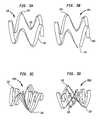
- FIG. 5 ais a perspective views of solid ring-shaped wave washer of the type which is utilized in conjunction with an embodiment of the present invention
- FIG. 5 bis a perspective view of a slotted ring-shaped wave washer of the type which is utilized in conjunction with a similar embodiment of the present invention
- FIGS. 5 c and 5 dare perspective and top views of a spiral-shaped wave washer of the type which is utilized in conjunction with another embodiment of the present invention
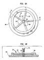
- FIGS. 6 a and 6 bare top and side perspective views of a securing pin assembly and screw for securing a wave washer to a base plate;
- FIG. 7is a side cross-section view of a first embodiment of the present invention which utilizes ring-shaped wave washer, of the type shown in FIGS. 5 a and 5 b ;
- FIG. 8is a side cross-section view of another embodiment of the present invention which utilizes spiral-shaped wave washer, of the type shown in FIGS. 5 c and 5 d;
- FIGS. 3 a and 3 bside cross-section views of the top and bottom plate members 100 a 100 b of a first embodiment of the present invention is shown. More particularly, in this embodiment, the upper and lower plates 100 a , 100 b are substantially identical. As the device is designed to be positioned between the facing surfaces of adjacent vertebral bodies, the plates include substantially flat surface portions 102 a , 102 b which seat against the opposing bone surfaces. In addition, the plates are to mate with the bone surfaces in such a way as to not rotate relative thereto. It is, therefore, preferred that the plates should include a porous coating 104 a , 104 b into which the bone of the vertebral body can grow.
- An additional threaded hole 106 a , 106 bis provided in each plate such that the interior of the device may be readily accessed if a need should arise.
- the plates 100 a , 100 bfurther include a circumferential flange 108 a , 108 b .
- the flange 108 a , 108 bmay be offset with respect to the front 110 a , 110 b and rear 111 a , 111 b orientation of the overall assembly. More particularly, the offset nature of the flanges 108 a , 108 b is exhibited in the non-symmetric appearance of each flange as it circumscribes the corresponding plate 100 a , 100 b .
- the portion of the flange 108 a , 108 b which corresponds to the rear 111 a , 111 b of the deviceis shorter than the portion corresponding to the front 110 a , 110 b of the device.
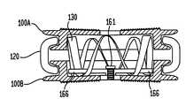
- FIG. 4a partially assembled embodiment of the present invention is provided in a side cross-section view, wherein the upper and lower plates 100 a , 100 b illustrated in FIGS. 3 a and 3 b are joined by means of a circumferential wall 120 . More particularly, between the base plates 100 a , 100 b , on the exterior of the device, there is included a circumferential wall 120 which is resilient and which is provided to prevents vessels and tissues from entering within the interior of the device. It is preferred that the resilient wall 120 comprise a porous fabric or a semi-impermiable elastomeric material. The wall 120 is further designs to couple to the flanges 108 a , 108 b of the corresponding plates 100 a , 100 b.
- the force restoring elementcomprises a ring-shaped wave washer element 130 .
- the wave washer 130is continuous, in that it does not include a radial break.
- the ring-shaped elementmaintains a circumferentially complete 360 degrees.
- the wave washer 130is so named inasmuch as its circumferential conformation includes a rising and falling undulating edge 132 , which, while maintaining a constant radius, creates a periodic arches 134 and valleys 136 .
- the restoring force of a continuous wave washer of the type illustrated in FIG. 5 ais proportional to the elastic properties of the material. As a compressive load is applied to the continuous ring-shaped washer, the forces are directed down onto the arches 134 and up against the valleys 136 . A significant fraction of these forces are immediately translated into hoop stresses which apply stresses directed toward radially expanding the washer. This hoop stress is also counterbalanced by the material strength of the washer.
- FIG. 5 billustrates an alternative ring-shaped wave washer for use with the present invention, which wave washer 140 is radially slotted.
- This radial slot 142permits the compressive load which is applied to the washer down onto the arches 144 and up against the valleys 146 to cause the ring to deflect such that the slot 142 closes.
- the difference between the radially slotted washer of FIG. 5 b , and the continuous washer of FIG. 5 ais that the continuous washer 130 responds to a compressive load by deflecting radially (with a very high stress to deflection ratio), whereas the radially slotted washer 140 deflects circumferentially, closing the slot 142 (this is characteristic of a much lower stress to deflection ratio).
- the spiral-shaped wave washers 150 a , 150 beach comprise a spirally wound band of material (as above, a titanium alloy or stainless steel is preferable, although other suitable surgical materials may be found to function adequately).
- the spirally wound wave washers 150 a , 150 b of this embodiment styleincludes a series of alternating and undulating arches 154 and valley 156 which extend continuously around the spiral.
- the wave washer in FIG. 5 cshows a washer in which the series of arches and valleys are radially aligned. Alternatively, in FIG. 5 d , the arches and valleys are not aligned.
- a first method of securing a wave washer(either the ring-shaped washers of FIGS. 5 a and 5 b , or the spiral-shaped washer of FIG. 5 c ) to a base plate 168 is provided.
- the pin assembly 160comprises a central hub portion 162 which is flat and includes a threaded hole, having substantially the same diameter and threading as the hole 106 a or 106 b in the corresponding base plate 100 a or 100 b .
- the screw 161is designed to secure the pin assembly to the base plate.
- the pin assembly 160further includes a plurality of radially extending thin shafts 166 . These shafts extend outwardly and upwardly from the base plate, aligning themselves in the arches and valleys of the corresponding washer, thereby securing it to the base plate.
- FIGS. 3 a , 3 b and 5 dthe means for securing the non-aligned spiral-shaped wave washer is now described.
- a midpoint (of a valley 156 ) of the spiral band of the wave washer having non-aligned arches 154 and valleys 156includes a threaded hole 159 which aligns with the threaded hole 106 a or 106 b in the base plate to which it is to be secured.
- the screw 161 shown in FIGS. 6 a and 6 bsecures the washer to the base plate through the aligned holes.
- FIG. 7an integrated device embodying the principles of the present invention is provided in a side cross-section view.
- the base plates 100 a , 100 bare disposed in a spaced apart relationship such that the opposing inner surfaces are approximately parallel and facing one another.
- a single ring-shaped wave washer 130 or 140is disposed between the plates, and retained therein by the circumferential flanges 108 a , 108 b .
- the ring-shaped wave washer 130 or 140is further constrained against rotational motion by a securing pin assembly 160 , and more particularly by the radially extending thin shafts 166 .
- a flexible circumferential skirt 120is provided around the entirety of the device, such that the tissue of the patient may not grow into, and thereby cause pain, or inhibit the functionality of the device. It shall be understood that a very similar design would accommodate a spiral-shaped wave washer 150 a as an alternative to the ring-shaped wave washer, so long as the arches and valleys of the spiral-shaped wave washer are radially aligned, as is shown in FIG. 5 c.
- FIG. 8an alternative integrated device embodying the principles of the present invention is provided in a side cross-section view.
- the base plates 100 a , 100 bare disposed in a spaced apart relationship such that the opposing inner surfaces are approximately parallel and facing one another.
- a single spiral-shaped wave washer 150 bis disposed between the plates, and retained therein by the circumferential flanges 108 a , 108 b .
- the spiral-shaped wave washer 150 bis further constrained against undesirable translation within the assembly by means of the screw 161 which extends through the central hole 159 of the washer 150 b and the hole 106 b in the base plate 100 b .
- a flexible circumferential skirt 120is provided around the entirety of the device, such that the tissue of the patient may not grow into, and thereby cause pain, or inhibit the functionality of the device.
Landscapes
- Health & Medical Sciences (AREA)
- Engineering & Computer Science (AREA)
- Biomedical Technology (AREA)
- Neurology (AREA)
- Orthopedic Medicine & Surgery (AREA)
- Cardiology (AREA)
- Oral & Maxillofacial Surgery (AREA)
- Transplantation (AREA)
- Heart & Thoracic Surgery (AREA)
- Vascular Medicine (AREA)
- Life Sciences & Earth Sciences (AREA)
- Animal Behavior & Ethology (AREA)
- General Health & Medical Sciences (AREA)
- Public Health (AREA)
- Veterinary Medicine (AREA)
- Prostheses (AREA)
Abstract
Description
Claims (19)
Priority Applications (2)
| Application Number | Priority Date | Filing Date | Title |
|---|---|---|---|
| US10/272,580US6758861B2 (en) | 2001-07-16 | 2002-10-16 | Intervertebral spacer device having a wave washer force restoring element |
| US10/833,738US7314487B2 (en) | 2001-07-16 | 2004-04-28 | Intervertebral spacer device having a wave washer force restoring element |
Applications Claiming Priority (2)
| Application Number | Priority Date | Filing Date | Title |
|---|---|---|---|
| US09/906,117US6468310B1 (en) | 2001-07-16 | 2001-07-16 | Intervertebral spacer device having a wave washer force restoring element |
| US10/272,580US6758861B2 (en) | 2001-07-16 | 2002-10-16 | Intervertebral spacer device having a wave washer force restoring element |
Related Parent Applications (1)
| Application Number | Title | Priority Date | Filing Date |
|---|---|---|---|
| US09/906,117ContinuationUS6468310B1 (en) | 2001-07-16 | 2001-07-16 | Intervertebral spacer device having a wave washer force restoring element |
Related Child Applications (1)
| Application Number | Title | Priority Date | Filing Date |
|---|---|---|---|
| US10/833,738ContinuationUS7314487B2 (en) | 2001-07-16 | 2004-04-28 | Intervertebral spacer device having a wave washer force restoring element |
Publications (2)
| Publication Number | Publication Date |
|---|---|
| US20030040801A1 US20030040801A1 (en) | 2003-02-27 |
| US6758861B2true US6758861B2 (en) | 2004-07-06 |
Family
ID=25421960
Family Applications (3)
| Application Number | Title | Priority Date | Filing Date |
|---|---|---|---|
| US09/906,117Expired - LifetimeUS6468310B1 (en) | 2001-07-16 | 2001-07-16 | Intervertebral spacer device having a wave washer force restoring element |
| US10/272,580Expired - Fee RelatedUS6758861B2 (en) | 2001-07-16 | 2002-10-16 | Intervertebral spacer device having a wave washer force restoring element |
| US10/833,738Expired - Fee RelatedUS7314487B2 (en) | 2001-07-16 | 2004-04-28 | Intervertebral spacer device having a wave washer force restoring element |
Family Applications Before (1)
| Application Number | Title | Priority Date | Filing Date |
|---|---|---|---|
| US09/906,117Expired - LifetimeUS6468310B1 (en) | 2001-07-16 | 2001-07-16 | Intervertebral spacer device having a wave washer force restoring element |
Family Applications After (1)
| Application Number | Title | Priority Date | Filing Date |
|---|---|---|---|
| US10/833,738Expired - Fee RelatedUS7314487B2 (en) | 2001-07-16 | 2004-04-28 | Intervertebral spacer device having a wave washer force restoring element |
Country Status (1)
| Country | Link |
|---|---|
| US (3) | US6468310B1 (en) |
Cited By (82)
| Publication number | Priority date | Publication date | Assignee | Title |
|---|---|---|---|---|
| US20040106998A1 (en)* | 2002-10-04 | 2004-06-03 | Ferree Bret A. | Multiaxial artificial disc replacements |
| US20040267367A1 (en)* | 2003-06-30 | 2004-12-30 | Depuy Acromed, Inc | Intervertebral implant with conformable endplate |
| US20050060036A1 (en)* | 2003-05-21 | 2005-03-17 | Robert Schultz | Spinal column implant |
| US20050209698A1 (en)* | 2003-08-05 | 2005-09-22 | Gordon Charles R | Expandable intervertebral implant |
| US6986789B2 (en) | 2003-08-22 | 2006-01-17 | Aesculap Ag & Co. Kg | Intervertebral implant |
| US20060149381A1 (en)* | 2004-12-30 | 2006-07-06 | Kim Chong C | Prosthetic spinal discs |
| US7198644B2 (en) | 2003-07-08 | 2007-04-03 | Aesculap Ag & Co. Kg | Intervertebral implant |
| US20070191958A1 (en)* | 2006-02-15 | 2007-08-16 | Abdou M S | Devices and Methods for Inter-Vertebral Orthopedic Device Placement |
| US20070270972A1 (en)* | 2003-08-05 | 2007-11-22 | Southwest Research Institute | Artificial functional spinal unit system and method for use |
| US20070282448A1 (en)* | 2006-05-26 | 2007-12-06 | Abdou M S | Inter-Vertebral Disc Motion Devices and Methods of Use |
| US20080154381A1 (en)* | 2006-12-21 | 2008-06-26 | Rob Gene Parrish | Intervertebral disc spacer |
| US20080183295A1 (en)* | 2006-11-20 | 2008-07-31 | Joseph Aferzon | Implantable spinal disk |
| US20090105829A1 (en)* | 2007-10-22 | 2009-04-23 | Gimbel Jonathan A | Dampener system for a posterior stabilization system with a variable length elongated member |
| US20090105827A1 (en)* | 2007-10-22 | 2009-04-23 | Gimbel Jonathan A | Dampener system for a posterior stabilization system with a fixed length elongated member |
| US20090157185A1 (en)* | 2007-12-18 | 2009-06-18 | Chong Chol Kim | Prosthetic Monolithic Spinal Discs and Method of Customizing and Constructing Discs |
| US7549995B2 (en) | 2003-07-08 | 2009-06-23 | Aesculap Ag | Surgical instrument for handling an implant |
| US7585325B2 (en) | 2004-06-16 | 2009-09-08 | Aesculap Ag | Intervertebral implant |
| US7655045B2 (en) | 2003-05-06 | 2010-02-02 | Aesculap Implant Systems, Llc | Artificial intervertebral disc |
| US7674296B2 (en) | 2005-04-21 | 2010-03-09 | Globus Medical, Inc. | Expandable vertebral prosthesis |
| US7799081B2 (en) | 2004-09-14 | 2010-09-21 | Aeolin, Llc | System and method for spinal fusion |
| US7815648B2 (en) | 2004-06-02 | 2010-10-19 | Facet Solutions, Inc | Surgical measurement systems and methods |
| US7832409B2 (en) | 2003-05-06 | 2010-11-16 | Aesculap Implant Systems, Llc | Method of inserting an artificial intervertebral disc |
| US7909869B2 (en) | 2003-08-05 | 2011-03-22 | Flexuspine, Inc. | Artificial spinal unit assemblies |
| US7914560B2 (en) | 2004-02-17 | 2011-03-29 | Gmedelaware 2 Llc | Spinal facet implant with spherical implant apposition surface and bone bed and methods of use |
| US7959677B2 (en) | 2007-01-19 | 2011-06-14 | Flexuspine, Inc. | Artificial functional spinal unit system and method for use |
| US20110208307A1 (en)* | 2010-02-22 | 2011-08-25 | Synthes Usa, Llc | Total disc replacement with w-shaped spring elements |
| US8118869B2 (en) | 2006-03-08 | 2012-02-21 | Flexuspine, Inc. | Dynamic interbody device |
| US8162994B2 (en) | 2007-10-22 | 2012-04-24 | Flexuspine, Inc. | Posterior stabilization system with isolated, dual dampener systems |
| US8187330B2 (en) | 2007-10-22 | 2012-05-29 | Flexuspine, Inc. | Dampener system for a posterior stabilization system with a variable length elongated member |
| US8206418B2 (en) | 2007-01-10 | 2012-06-26 | Gmedelaware 2 Llc | System and method for facet joint replacement with detachable coupler |
| US8267965B2 (en) | 2007-10-22 | 2012-09-18 | Flexuspine, Inc. | Spinal stabilization systems with dynamic interbody devices |
| US8282683B2 (en) | 2010-04-12 | 2012-10-09 | Globus Medical, Inc. | Expandable vertebral implant |
| US8303660B1 (en) | 2006-04-22 | 2012-11-06 | Samy Abdou | Inter-vertebral disc prosthesis with variable rotational stop and methods of use |
| US8523912B2 (en) | 2007-10-22 | 2013-09-03 | Flexuspine, Inc. | Posterior stabilization systems with shared, dual dampener systems |
| US8721723B2 (en) | 2009-01-12 | 2014-05-13 | Globus Medical, Inc. | Expandable vertebral prosthesis |
| US8777994B2 (en) | 2004-06-02 | 2014-07-15 | Gmedelaware 2 Llc | System and method for multiple level facet joint arthroplasty and fusion |
| US8940051B2 (en) | 2011-03-25 | 2015-01-27 | Flexuspine, Inc. | Interbody device insertion systems and methods |
| US9492288B2 (en) | 2013-02-20 | 2016-11-15 | Flexuspine, Inc. | Expandable fusion device for positioning between adjacent vertebral bodies |
| US9517144B2 (en) | 2014-04-24 | 2016-12-13 | Exactech, Inc. | Limited profile intervertebral implant with incorporated fastening mechanism |
| US9526627B2 (en) | 2011-11-17 | 2016-12-27 | Exactech, Inc. | Expandable interbody device system and method |
| US9707091B2 (en) | 2010-04-12 | 2017-07-18 | Globus Medical, Inc. | Expandable vertebral implant |
| US9724207B2 (en) | 2003-02-14 | 2017-08-08 | DePuy Synthes Products, Inc. | In-situ formed intervertebral fusion device and method |
| US9913735B2 (en) | 2010-04-12 | 2018-03-13 | Globus Medical, Inc. | Angling inserter tool for expandable vertebral implant |
| US9949769B2 (en) | 2004-03-06 | 2018-04-24 | DePuy Synthes Products, Inc. | Dynamized interspinal implant |
| US10130489B2 (en) | 2010-04-12 | 2018-11-20 | Globus Medical, Inc. | Expandable vertebral implant |
| US10238500B2 (en) | 2002-06-27 | 2019-03-26 | DePuy Synthes Products, Inc. | Intervertebral disc |
| US10398565B2 (en) | 2014-04-24 | 2019-09-03 | Choice Spine, Llc | Limited profile intervertebral implant with incorporated fastening and locking mechanism |
| US10543107B2 (en) | 2009-12-07 | 2020-01-28 | Samy Abdou | Devices and methods for minimally invasive spinal stabilization and instrumentation |
| US10548740B1 (en) | 2016-10-25 | 2020-02-04 | Samy Abdou | Devices and methods for vertebral bone realignment |
| US10575961B1 (en) | 2011-09-23 | 2020-03-03 | Samy Abdou | Spinal fixation devices and methods of use |
| US10695105B2 (en) | 2012-08-28 | 2020-06-30 | Samy Abdou | Spinal fixation devices and methods of use |
| US10857003B1 (en) | 2015-10-14 | 2020-12-08 | Samy Abdou | Devices and methods for vertebral stabilization |
| US10888433B2 (en) | 2016-12-14 | 2021-01-12 | DePuy Synthes Products, Inc. | Intervertebral implant inserter and related methods |
| US10918498B2 (en) | 2004-11-24 | 2021-02-16 | Samy Abdou | Devices and methods for inter-vertebral orthopedic device placement |
| US10940016B2 (en) | 2017-07-05 | 2021-03-09 | Medos International Sarl | Expandable intervertebral fusion cage |
| US10966840B2 (en) | 2010-06-24 | 2021-04-06 | DePuy Synthes Products, Inc. | Enhanced cage insertion assembly |
| US10973648B1 (en) | 2016-10-25 | 2021-04-13 | Samy Abdou | Devices and methods for vertebral bone realignment |
| US10973652B2 (en) | 2007-06-26 | 2021-04-13 | DePuy Synthes Products, Inc. | Highly lordosed fusion cage |
| US11006982B2 (en) | 2012-02-22 | 2021-05-18 | Samy Abdou | Spinous process fixation devices and methods of use |
| US11173040B2 (en) | 2012-10-22 | 2021-11-16 | Cogent Spine, LLC | Devices and methods for spinal stabilization and instrumentation |
| US11179248B2 (en) | 2018-10-02 | 2021-11-23 | Samy Abdou | Devices and methods for spinal implantation |
| US11273050B2 (en) | 2006-12-07 | 2022-03-15 | DePuy Synthes Products, Inc. | Intervertebral implant |
| US11344424B2 (en) | 2017-06-14 | 2022-05-31 | Medos International Sarl | Expandable intervertebral implant and related methods |
| US11426290B2 (en) | 2015-03-06 | 2022-08-30 | DePuy Synthes Products, Inc. | Expandable intervertebral implant, system, kit and method |
| US11426286B2 (en) | 2020-03-06 | 2022-08-30 | Eit Emerging Implant Technologies Gmbh | Expandable intervertebral implant |
| US11446155B2 (en) | 2017-05-08 | 2022-09-20 | Medos International Sarl | Expandable cage |
| US11446156B2 (en) | 2018-10-25 | 2022-09-20 | Medos International Sarl | Expandable intervertebral implant, inserter instrument, and related methods |
| US11452607B2 (en) | 2010-10-11 | 2022-09-27 | DePuy Synthes Products, Inc. | Expandable interspinous process spacer implant |
| US11497619B2 (en) | 2013-03-07 | 2022-11-15 | DePuy Synthes Products, Inc. | Intervertebral implant |
| US11510788B2 (en) | 2016-06-28 | 2022-11-29 | Eit Emerging Implant Technologies Gmbh | Expandable, angularly adjustable intervertebral cages |
| US11596522B2 (en) | 2016-06-28 | 2023-03-07 | Eit Emerging Implant Technologies Gmbh | Expandable and angularly adjustable intervertebral cages with articulating joint |
| US11602438B2 (en) | 2008-04-05 | 2023-03-14 | DePuy Synthes Products, Inc. | Expandable intervertebral implant |
| US11607321B2 (en) | 2009-12-10 | 2023-03-21 | DePuy Synthes Products, Inc. | Bellows-like expandable interbody fusion cage |
| US11612491B2 (en) | 2009-03-30 | 2023-03-28 | DePuy Synthes Products, Inc. | Zero profile spinal fusion cage |
| US11654033B2 (en) | 2010-06-29 | 2023-05-23 | DePuy Synthes Products, Inc. | Distractible intervertebral implant |
| US11737881B2 (en) | 2008-01-17 | 2023-08-29 | DePuy Synthes Products, Inc. | Expandable intervertebral implant and associated method of manufacturing the same |
| US11752009B2 (en) | 2021-04-06 | 2023-09-12 | Medos International Sarl | Expandable intervertebral fusion cage |
| US11850160B2 (en) | 2021-03-26 | 2023-12-26 | Medos International Sarl | Expandable lordotic intervertebral fusion cage |
| US11911287B2 (en) | 2010-06-24 | 2024-02-27 | DePuy Synthes Products, Inc. | Lateral spondylolisthesis reduction cage |
| USRE49973E1 (en) | 2013-02-28 | 2024-05-21 | DePuy Synthes Products, Inc. | Expandable intervertebral implant, system, kit and method |
| US12090064B2 (en) | 2022-03-01 | 2024-09-17 | Medos International Sarl | Stabilization members for expandable intervertebral implants, and related systems and methods |
| US12440346B2 (en) | 2023-03-31 | 2025-10-14 | DePuy Synthes Products, Inc. | Expandable intervertebral implant |
Families Citing this family (131)
| Publication number | Priority date | Publication date | Assignee | Title |
|---|---|---|---|---|
| FR2897259B1 (en) | 2006-02-15 | 2008-05-09 | Ldr Medical Soc Par Actions Si | INTERSOMATIC TRANSFORAMINAL CAGE WITH INTERBREBAL FUSION GRAFT AND CAGE IMPLANTATION INSTRUMENT |
| US7918888B2 (en)* | 1999-10-13 | 2011-04-05 | Hamada James S | Spinal fusion instrumentation, implant and method |
| FR2808995B1 (en) | 2000-05-18 | 2003-02-21 | Aesculap Sa | INTERSOMATIC CAGE WITH UNIFIED GRAFT |
| US8940047B2 (en)* | 2001-02-15 | 2015-01-27 | Spinecore, Inc. | Intervertebral spacer device having recessed notch pairs for manipulation using a surgical tool |
| US7575576B2 (en)* | 2001-07-16 | 2009-08-18 | Spinecore, Inc. | Wedge ramp distractor and related methods for use in implanting artificial intervertebral discs |
| US7223291B2 (en)* | 2001-07-16 | 2007-05-29 | Spinecore, Inc. | Intervertebral spacer device having engagement hole pairs for manipulation using a surgical tool |
| US6740117B2 (en)* | 2001-02-15 | 2004-05-25 | Spinecore, Inc. | Intervertebral spacer device having a radially thinning slotted belleville spring |
| US6863689B2 (en)* | 2001-07-16 | 2005-03-08 | Spinecore, Inc. | Intervertebral spacer having a flexible wire mesh vertebral body contact element |
| US6607559B2 (en)* | 2001-07-16 | 2003-08-19 | Spine Care, Inc. | Trial intervertebral distraction spacers |
| US7169182B2 (en)* | 2001-07-16 | 2007-01-30 | Spinecore, Inc. | Implanting an artificial intervertebral disc |
| US6989032B2 (en)* | 2001-07-16 | 2006-01-24 | Spinecore, Inc. | Artificial intervertebral disc |
| US6669730B2 (en) | 2001-02-15 | 2003-12-30 | Spinecore, Inc. | Intervertebral spacer device utilizing a spirally slotted belleville washer having radially extending grooves |
| US7563285B2 (en)* | 2001-07-16 | 2009-07-21 | Spinecore, Inc. | Artificial intervertebral disc utilizing a ball joint coupling |
| US7235081B2 (en)* | 2001-07-16 | 2007-06-26 | Spinecore, Inc. | Wedge plate inserter/impactor and related methods for use in implanting an artificial intervertebral disc |
| US8858564B2 (en) | 2001-02-15 | 2014-10-14 | Spinecore, Inc. | Wedge plate inserter/impactor and related methods for use in implanting an artificial intervertebral disc |
| US6673113B2 (en)* | 2001-10-18 | 2004-01-06 | Spinecore, Inc. | Intervertebral spacer device having arch shaped spring elements |
| FR2824261B1 (en) | 2001-05-04 | 2004-05-28 | Ldr Medical | INTERVERTEBRAL DISC PROSTHESIS AND IMPLEMENTATION METHOD AND TOOLS |
| US6607558B2 (en) | 2001-07-03 | 2003-08-19 | Axiomed Spine Corporation | Artificial disc |
| FR2827156B1 (en) | 2001-07-13 | 2003-11-14 | Ldr Medical | VERTEBRAL CAGE DEVICE WITH MODULAR FASTENING |
| US7153310B2 (en)* | 2001-07-16 | 2006-12-26 | Spinecore, Inc. | Vertebral bone distraction instruments |
| US6468310B1 (en)* | 2001-07-16 | 2002-10-22 | Third Millennium Engineering, Llc | Intervertebral spacer device having a wave washer force restoring element |
| US7695478B2 (en)* | 2001-07-16 | 2010-04-13 | Spinecore, Inc. | Insertion tool for use with intervertebral spacers |
| ATE426377T1 (en)* | 2001-07-16 | 2009-04-15 | Spinecore Inc | ARTIFICIAL DISC WITH A FORCE-RESTORING ELEMENT IN THE FORM OF A WAVE WASHER |
| US7118599B2 (en) | 2001-07-16 | 2006-10-10 | Spinecore, Inc. | Artificial intervertebral disc |
| US20070198092A1 (en)* | 2001-07-16 | 2007-08-23 | Spinecore, Inc. | System for inserting artificial intervertebral discs |
| US7160327B2 (en) | 2001-07-16 | 2007-01-09 | Spinecore, Inc. | Axially compressible artificial intervertebral disc having limited rotation using a captured ball and socket joint with a solid ball and compression locking post |
| US7771477B2 (en) | 2001-10-01 | 2010-08-10 | Spinecore, Inc. | Intervertebral spacer device utilizing a belleville washer having radially spaced concentric grooves |
| US20090177283A9 (en)* | 2001-10-01 | 2009-07-09 | Ralph James D | Intervertebral spacer device utilizing a spirally slotted belleville washer and a rotational mounting |
| US7713302B2 (en) | 2001-10-01 | 2010-05-11 | Spinecore, Inc. | Intervertebral spacer device utilizing a spirally slotted belleville washer having radially spaced concentric grooves |
| US20030083749A1 (en)* | 2001-10-31 | 2003-05-01 | Kuslich Stephen D. | Corpectomy device |
| FR2832917B1 (en)* | 2001-11-30 | 2004-09-24 | Spine Next Sa | ELASTICALLY DEFORMABLE INTERVERTEBRAL IMPLANT |
| US6736850B2 (en)* | 2001-12-28 | 2004-05-18 | Spinal Concepts, Inc. | Vertebral pseudo arthrosis device and method |
| US20080027548A9 (en) | 2002-04-12 | 2008-01-31 | Ferree Bret A | Spacerless artificial disc replacements |
| US8038713B2 (en) | 2002-04-23 | 2011-10-18 | Spinecore, Inc. | Two-component artificial disc replacements |
| US6706068B2 (en) | 2002-04-23 | 2004-03-16 | Bret A. Ferree | Artificial disc replacements with natural kinematics |
| CA2495404C (en) | 2002-08-15 | 2011-05-03 | Justin K. Coppes | Intervertebral disc implant |
| EP1542626B1 (en) | 2002-08-15 | 2012-09-26 | Synthes GmbH | Controlled artificial intervertebral disc implant |
| US7083649B2 (en) | 2002-10-29 | 2006-08-01 | St. Francis Medical Technologies, Inc. | Artificial vertebral disk replacement implant with translating pivot point |
| US6966929B2 (en) | 2002-10-29 | 2005-11-22 | St. Francis Medical Technologies, Inc. | Artificial vertebral disk replacement implant with a spacer |
| US7497859B2 (en) | 2002-10-29 | 2009-03-03 | Kyphon Sarl | Tools for implanting an artificial vertebral disk |
| US7273496B2 (en) | 2002-10-29 | 2007-09-25 | St. Francis Medical Technologies, Inc. | Artificial vertebral disk replacement implant with crossbar spacer and method |
| FR2846550B1 (en) | 2002-11-05 | 2006-01-13 | Ldr Medical | INTERVERTEBRAL DISC PROSTHESIS |
| FR2851157B1 (en)* | 2003-02-13 | 2005-12-09 | Spinevision | INTERVERTEBRAL PROSTHESIS |
| US6908484B2 (en) | 2003-03-06 | 2005-06-21 | Spinecore, Inc. | Cervical disc replacement |
| EP1605872B1 (en)* | 2003-03-24 | 2009-09-30 | Synthes GmbH | Vertebral disc or intervertebral disc prosthesis |
| EP1610740A4 (en) | 2003-04-04 | 2009-04-08 | Theken Disc Llc | Artificial disc prosthesis |
| US7407513B2 (en)* | 2003-05-02 | 2008-08-05 | Smart Disc, Inc. | Artificial spinal disk |
| US7442211B2 (en) | 2003-05-27 | 2008-10-28 | Spinalmotion, Inc. | Intervertebral prosthetic disc |
| US7537612B2 (en)* | 2003-06-20 | 2009-05-26 | Warsaw Orthopedic, Inc. | Lumbar composite nucleus |
| EP1646336B1 (en)* | 2003-07-22 | 2009-07-08 | Synthes GmbH | Intervertebral implant comprising dome-shaped joint surfaces |
| US9700450B2 (en)* | 2003-07-28 | 2017-07-11 | Baronova, Inc. | Devices and methods for gastrointestinal stimulation |
| US7811329B2 (en) | 2003-07-31 | 2010-10-12 | Globus Medical | Transforaminal prosthetic spinal disc replacement and methods thereof |
| US7713304B2 (en) | 2003-07-31 | 2010-05-11 | Globus Medical, Inc. | Transforaminal prosthetic spinal disc replacement |
| US7621956B2 (en)* | 2003-07-31 | 2009-11-24 | Globus Medical, Inc. | Prosthetic spinal disc replacement |
| US7458988B2 (en)* | 2003-11-05 | 2008-12-02 | Warsaw Orthopedic, Inc. | Compressible corpectomy device |
| US7520899B2 (en) | 2003-11-05 | 2009-04-21 | Kyphon Sarl | Laterally insertable artificial vertebral disk replacement implant with crossbar spacer |
| EP1532950B1 (en)* | 2003-11-18 | 2008-03-26 | Zimmer GmbH | Spinal disc prosthesis |
| US7670377B2 (en) | 2003-11-21 | 2010-03-02 | Kyphon Sarl | Laterally insertable artifical vertebral disk replacement implant with curved spacer |
| US20050154462A1 (en) | 2003-12-02 | 2005-07-14 | St. Francis Medical Technologies, Inc. | Laterally insertable artificial vertebral disk replacement implant with translating pivot point |
| US7481839B2 (en) | 2003-12-02 | 2009-01-27 | Kyphon Sarl | Bioresorbable interspinous process implant for use with intervertebral disk remediation or replacement implants and procedures |
| US7217291B2 (en)* | 2003-12-08 | 2007-05-15 | St. Francis Medical Technologies, Inc. | System and method for replacing degenerated spinal disks |
| EP2113227B1 (en) | 2004-02-04 | 2015-07-29 | LDR Medical | Intervertebral disc prosthesis |
| FR2865629B1 (en) | 2004-02-04 | 2007-01-26 | Ldr Medical | INTERVERTEBRAL DISC PROSTHESIS |
| US7393361B2 (en)* | 2004-02-20 | 2008-07-01 | Spinecore, Inc. | Artificial intervertebral disc having a bored semispherical bearing with a compression locking post and retaining caps |
| US7468076B2 (en)* | 2004-02-20 | 2008-12-23 | Spinecore, Inc. | Artificial intervertebral disc having a universal joint |
| FR2869528B1 (en) | 2004-04-28 | 2007-02-02 | Ldr Medical | INTERVERTEBRAL DISC PROSTHESIS |
| MXPA06014714A (en) | 2004-06-30 | 2007-06-22 | Synergy Disc Replacement Inc | Artificial spinal disc. |
| US9237958B2 (en) | 2004-06-30 | 2016-01-19 | Synergy Disc Replacement Inc. | Joint prostheses |
| US8172904B2 (en) | 2004-06-30 | 2012-05-08 | Synergy Disc Replacement, Inc. | Artificial spinal disc |
| US8454699B2 (en) | 2004-06-30 | 2013-06-04 | Synergy Disc Replacement, Inc | Systems and methods for vertebral disc replacement |
| US7481840B2 (en) | 2004-09-29 | 2009-01-27 | Kyphon Sarl | Multi-piece artificial spinal disk replacement device with selectably positioning articulating element |
| US7575600B2 (en) | 2004-09-29 | 2009-08-18 | Kyphon Sarl | Artificial vertebral disk replacement implant with translating articulation contact surface and method |
| FR2876900B1 (en)* | 2004-10-22 | 2007-01-05 | Sdgi Holdings Inc | INTERVERTEBRAL IMPLANT AND DEVICE FOR STABILIZING THE RACHIS COMPRISING THE SAME |
| FR2879436B1 (en) | 2004-12-22 | 2007-03-09 | Ldr Medical | INTERVERTEBRAL DISC PROSTHESIS |
| US7578848B2 (en)* | 2005-03-03 | 2009-08-25 | Cervical Xpand, Llc | Intervertebral stabilizer |
| US20060276899A1 (en)* | 2005-06-03 | 2006-12-07 | Zipnick Richard I | Minimally invasive apparatus to manipulate and revitalize spinal column disc |
| DE102005025685B4 (en)* | 2005-06-03 | 2015-05-21 | Mathys Ag Bettlach | Intervertebral disc implant |
| FR2887762B1 (en) | 2005-06-29 | 2007-10-12 | Ldr Medical Soc Par Actions Si | INTERVERTEBRAL DISC PROSTHESIS INSERTION INSTRUMENTATION BETWEEN VERTEBRATES |
| US20070016301A1 (en)* | 2005-07-14 | 2007-01-18 | Medical Device Concepts Llc. | Multi-axial interbody spacer device |
| US20070016190A1 (en)* | 2005-07-14 | 2007-01-18 | Medical Device Concepts Llc | Dynamic spinal stabilization system |
| FR2891135B1 (en) | 2005-09-23 | 2008-09-12 | Ldr Medical Sarl | INTERVERTEBRAL DISC PROSTHESIS |
| FR2893838B1 (en) | 2005-11-30 | 2008-08-08 | Ldr Medical Soc Par Actions Si | PROSTHESIS OF INTERVERTEBRAL DISC AND INSTRUMENTATION OF INSERTION OF THE PROSTHESIS BETWEEN VERTEBRATES |
| US8231631B2 (en)* | 2006-03-20 | 2012-07-31 | Perception Raisonnement Action En Medecine | Distractor system |
| US11395626B2 (en) | 2006-12-07 | 2022-07-26 | DePuy Synthes Products, Inc. | Sensor for intervertebral fusion indicia |
| US7905922B2 (en) | 2006-12-20 | 2011-03-15 | Zimmer Spine, Inc. | Surgical implant suitable for replacement of an intervertebral disc |
| US7892285B2 (en)* | 2007-01-02 | 2011-02-22 | Zimmer Spine, Inc. | Universal joint total disc replacement |
| US8465546B2 (en) | 2007-02-16 | 2013-06-18 | Ldr Medical | Intervertebral disc prosthesis insertion assemblies |
| FR2916956B1 (en) | 2007-06-08 | 2012-12-14 | Ldr Medical | INTERSOMATIC CAGE, INTERVERTEBRAL PROSTHESIS, ANCHORING DEVICE AND IMPLANTATION INSTRUMENTATION |
| EP2018832B1 (en)* | 2007-07-26 | 2011-09-21 | BIEDERMANN MOTECH GmbH | Intervertebral disc prosthesis |
| EP2244671A4 (en)* | 2008-01-25 | 2013-03-20 | Spinalmotion Inc | INTERVERTEBRAL PROSTHETIC DISC WITH SHOCK-ABSORBING CENTRAL COMPRISING DISC SPRINGS |
| EP2268233A4 (en)* | 2008-02-28 | 2013-04-10 | Kinetic Spine Technologies Inc | Intervertebral disc prosthesis having ball and ring structure |
| US8147499B2 (en)* | 2008-04-24 | 2012-04-03 | Spinecore, Inc. | Dynamic distractor |
| ES2361099B1 (en)* | 2008-05-26 | 2012-05-08 | Rudolf Morgenstern Lopez | "INTERVERTEBRAL PROSTHESIS" |
| US11224521B2 (en) | 2008-06-06 | 2022-01-18 | Providence Medical Technology, Inc. | Cervical distraction/implant delivery device |
| CA2725811A1 (en) | 2008-06-06 | 2009-12-10 | Providence Medical Technology, Inc. | Facet joint implants and delivery tools |
| US8172902B2 (en) | 2008-07-17 | 2012-05-08 | Spinemedica, Llc | Spinal interbody spacers |
| US7927375B2 (en) | 2008-09-12 | 2011-04-19 | Doty Keith L | Dynamic six-degrees-of-freedom intervertebral spinal disc prosthesis |
| EP2408382A4 (en) | 2009-03-13 | 2013-06-19 | Univ Toledo | FOLDING CAGE LITTLE INVASIVE |
| US8226724B2 (en)* | 2009-06-18 | 2012-07-24 | Doty Keith L | Intervertebral spinal disc prosthesis |
| KR101687435B1 (en) | 2009-07-06 | 2016-12-19 | 신세스 게엠바하 | Expandable fixation assemblies |
| CN105326585B (en) | 2009-09-17 | 2018-12-11 | Ldr控股公司 | Intervertebral implant with extensible bone anchoring element |
| US8277509B2 (en) | 2009-12-07 | 2012-10-02 | Globus Medical, Inc. | Transforaminal prosthetic spinal disc apparatus |
| WO2011080535A1 (en) | 2009-12-31 | 2011-07-07 | Lrd Medical | Anchoring device, intervertebral implant and implantation instrument |
| US8486116B2 (en) | 2010-01-08 | 2013-07-16 | Biomet Manufacturing Ring Corporation | Variable angle locking screw |
| KR101052833B1 (en)* | 2010-10-28 | 2011-07-29 | 박경우 | Flexible intervertebral cage |
| US8496713B2 (en)* | 2010-12-10 | 2013-07-30 | Globus Medical, Inc. | Spine stabilization device and methods |
| US8728129B2 (en) | 2011-01-07 | 2014-05-20 | Biomet Manufacturing, Llc | Variable angled locking screw |
| US8998991B2 (en)* | 2011-02-23 | 2015-04-07 | Globus Medical, Inc. | Six degree spine stabilization devices and methods |
| US8277505B1 (en) | 2011-06-10 | 2012-10-02 | Doty Keith L | Devices for providing up to six-degrees of motion having kinematically-linked components and methods of use |
| HK1201138A1 (en)* | 2011-10-10 | 2015-08-28 | William Casey Fox | Shape changing bone implant for enhanced healing |
| US9017410B2 (en) | 2011-10-26 | 2015-04-28 | Globus Medical, Inc. | Artificial discs |
| US8287598B1 (en) | 2011-12-05 | 2012-10-16 | TrueMotion Spine, Inc. | True spinal motion preserving, shock absorbing, intervertebral spinal disc prosthesis |
| FR2987256B1 (en) | 2012-02-24 | 2014-08-08 | Ldr Medical | ANCHORING DEVICE FOR INTERVERTEBRAL IMPLANT, INTERVERTEBRAL IMPLANT AND IMPLANTATION INSTRUMENTATION |
| US9393126B2 (en)* | 2012-04-20 | 2016-07-19 | Peter L. Mayer | Bilaterally placed disc prosthesis for spinal implant and method of bilateral placement |
| US9364339B2 (en)* | 2012-04-30 | 2016-06-14 | Peter L. Mayer | Unilaterally placed expansile spinal prosthesis |
| EP2877127B1 (en) | 2012-07-26 | 2019-08-21 | Synthes GmbH | Expandable implant |
| US20140067069A1 (en) | 2012-08-30 | 2014-03-06 | Interventional Spine, Inc. | Artificial disc |
| US9198770B2 (en) | 2013-07-31 | 2015-12-01 | Globus Medical, Inc. | Artificial disc devices and related methods of use |
| AU2015267055B2 (en) | 2014-05-27 | 2020-04-02 | Christopher U. Phan | Lateral mass fixation implant |
| US9913727B2 (en) | 2015-07-02 | 2018-03-13 | Medos International Sarl | Expandable implant |
| US10537436B2 (en) | 2016-11-01 | 2020-01-21 | DePuy Synthes Products, Inc. | Curved expandable cage |
| US11871968B2 (en) | 2017-05-19 | 2024-01-16 | Providence Medical Technology, Inc. | Spinal fixation access and delivery system |
| US20200289285A1 (en)* | 2017-11-16 | 2020-09-17 | Providence Medical Technology, Inc. | Arthroplasty implant for a facet joint |
| US11648128B2 (en) | 2018-01-04 | 2023-05-16 | Providence Medical Technology, Inc. | Facet screw and delivery device |
| US11096802B2 (en) | 2018-03-03 | 2021-08-24 | K2M, Inc. | Intervertebral trial with marker |
| CN213722665U (en)* | 2018-06-12 | 2021-07-20 | 深圳市立心科学有限公司 | Intervertebral fusion device with multiple buffering parts |
| US10893951B2 (en)* | 2018-08-07 | 2021-01-19 | Minimally Invasive Spinal Technology, LLC | Device and method for correcting spinal deformities in patients |
| WO2020061464A1 (en) | 2018-09-21 | 2020-03-26 | Providence Medical Technology, Inc. | Vertebral joint access and decortication devices and methods of using |
| US11701241B2 (en) | 2021-06-28 | 2023-07-18 | Spine Wave, Inc. | Bellows shaped spinal implant |
| US11826265B2 (en) | 2021-06-28 | 2023-11-28 | Spine Wave, Inc. | Bellows shaped spinal implant having gyroid lattice structures |
| US20240335296A1 (en)* | 2023-04-06 | 2024-10-10 | 33 Medical, Inc. | Minimally invasive compliant devices for total lumbar disc replacement |
Citations (11)
| Publication number | Priority date | Publication date | Assignee | Title |
|---|---|---|---|---|
| US4309777A (en)* | 1980-11-13 | 1982-01-12 | Patil Arun A | Artificial intervertebral disc |
| US5928284A (en)* | 1998-07-09 | 1999-07-27 | Mehdizadeh; Hamid M. | Disc replacement prosthesis |
| US6231609B1 (en)* | 1998-07-09 | 2001-05-15 | Hamid M. Mehdizadeh | Disc replacement prosthesis |
| US20020128714A1 (en)* | 1999-06-04 | 2002-09-12 | Mark Manasas | Orthopedic implant and method of making metal articles |
| US6454806B1 (en)* | 1999-07-26 | 2002-09-24 | Advanced Prosthetic Technologies, Inc. | Spinal surgical prosthesis |
| US6468310B1 (en)* | 2001-07-16 | 2002-10-22 | Third Millennium Engineering, Llc | Intervertebral spacer device having a wave washer force restoring element |
| US6520996B1 (en)* | 1999-06-04 | 2003-02-18 | Depuy Acromed, Incorporated | Orthopedic implant |
| US6527806B2 (en)* | 2001-07-16 | 2003-03-04 | Third Millennium Engineering, Llc | Intervertebral spacer device having a spiral wave washer force restoring element |
| US6527804B1 (en)* | 1998-12-11 | 2003-03-04 | Dimso (Distribution Medicale Du Sud-Quest) | Intervertebral disk prosthesis |
| US6579320B1 (en)* | 1998-12-11 | 2003-06-17 | Stryker Spine | Intervertebral disc prosthesis with contact blocks |
| US6723127B2 (en)* | 2001-07-16 | 2004-04-20 | Spine Core, Inc. | Artificial intervertebral disc having a wave washer force restoring element |
Family Cites Families (48)
| Publication number | Priority date | Publication date | Assignee | Title |
|---|---|---|---|---|
| SE391122B (en) | 1971-01-25 | 1977-02-07 | Cutter Lab | PROTESTS IN THE FORM OF A SPINE BONIC DISC AND PROCEDURES FOR MANUFACTURE THEREOF |
| CA1283501C (en) | 1987-02-12 | 1991-04-30 | Thomas P. Hedman | Artificial spinal disc |
| DE3809793A1 (en) | 1988-03-23 | 1989-10-05 | Link Waldemar Gmbh Co | SURGICAL INSTRUMENT SET |
| FR2659226B1 (en) | 1990-03-07 | 1992-05-29 | Jbs Sa | PROSTHESIS FOR INTERVERTEBRAL DISCS AND ITS IMPLEMENTATION INSTRUMENTS. |
| US5123926A (en)* | 1991-02-22 | 1992-06-23 | Madhavan Pisharodi | Artificial spinal prosthesis |
| US5425773A (en) | 1992-01-06 | 1995-06-20 | Danek Medical, Inc. | Intervertebral disk arthroplasty device |
| DE4208115A1 (en) | 1992-03-13 | 1993-09-16 | Link Waldemar Gmbh Co | DISC ENDOPROTHESIS |
| DE4208116C2 (en) | 1992-03-13 | 1995-08-03 | Link Waldemar Gmbh Co | Intervertebral disc prosthesis |
| US5676701A (en) | 1993-01-14 | 1997-10-14 | Smith & Nephew, Inc. | Low wear artificial spinal disc |
| US5383772A (en)* | 1993-11-04 | 1995-01-24 | Tecumseh Products Company | Scroll compressor stabilizer ring |
| US5458642A (en)* | 1994-01-18 | 1995-10-17 | Beer; John C. | Synthetic intervertebral disc |
| US5674296A (en) | 1994-11-14 | 1997-10-07 | Spinal Dynamics Corporation | Human spinal disc prosthesis |
| FR2728159B1 (en) | 1994-12-16 | 1997-06-27 | Tornier Sa | ELASTIC DISC PROSTHESIS |
| US5683465A (en) | 1996-03-18 | 1997-11-04 | Shinn; Gary Lee | Artificial intervertebral disk prosthesis |
| US5755796A (en) | 1996-06-06 | 1998-05-26 | Ibo; Ivo | Prosthesis of the cervical intervertebralis disk |
| US5666243A (en)* | 1996-09-03 | 1997-09-09 | Seagate Technology, Inc. | Spring loaded stacked actuator assembly |
| US5782832A (en) | 1996-10-01 | 1998-07-21 | Surgical Dynamics, Inc. | Spinal fusion implant and method of insertion thereof |
| US5895428A (en) | 1996-11-01 | 1999-04-20 | Berry; Don | Load bearing spinal joint implant |
| US5827328A (en)* | 1996-11-22 | 1998-10-27 | Buttermann; Glenn R. | Intervertebral prosthetic device |
| US5893889A (en) | 1997-06-20 | 1999-04-13 | Harrington; Michael | Artificial disc |
| US6146421A (en) | 1997-08-04 | 2000-11-14 | Gordon, Maya, Roberts And Thomas, Number 1, Llc | Multiple axis intervertebral prosthesis |
| AU8768998A (en) | 1997-08-04 | 1999-02-22 | Gordon, Maya, Roberts & Thomas Number 1 Llc | Multiple axis intervertebral prosthesis |
| US5824094A (en) | 1997-10-17 | 1998-10-20 | Acromed Corporation | Spinal disc |
| US5888226A (en) | 1997-11-12 | 1999-03-30 | Rogozinski; Chaim | Intervertebral prosthetic disc |
| US5899941A (en) | 1997-12-09 | 1999-05-04 | Chubu Bearing Kabushiki Kaisha | Artificial intervertebral disk |
| US5989291A (en)* | 1998-02-26 | 1999-11-23 | Third Millennium Engineering, Llc | Intervertebral spacer device |
| US6019792A (en) | 1998-04-23 | 2000-02-01 | Cauthen Research Group, Inc. | Articulating spinal implant |
| WO1999053871A1 (en) | 1998-04-23 | 1999-10-28 | Cauthen Research Group, Inc. | Articulating spinal implant |
| US6296664B1 (en) | 1998-06-17 | 2001-10-02 | Surgical Dynamics, Inc. | Artificial intervertebral disc |
| US6136031A (en) | 1998-06-17 | 2000-10-24 | Surgical Dynamics, Inc. | Artificial intervertebral disc |
| US6063121A (en) | 1998-07-29 | 2000-05-16 | Xavier; Ravi | Vertebral body prosthesis |
| US6113637A (en) | 1998-10-22 | 2000-09-05 | Sofamor Danek Holdings, Inc. | Artificial intervertebral joint permitting translational and rotational motion |
| US6151934A (en)* | 1998-10-23 | 2000-11-28 | Emhart Inc. | Lock assembly with over-torque defense system |
| US6039763A (en) | 1998-10-27 | 2000-03-21 | Disc Replacement Technologies, Inc. | Articulating spinal disc prosthesis |
| FR2787015B1 (en) | 1998-12-11 | 2001-04-27 | Dimso Sa | INTERVERTEBRAL DISC PROSTHESIS WITH COMPRESSIBLE BODY |
| FR2787014B1 (en) | 1998-12-11 | 2001-03-02 | Dimso Sa | INTERVERTEBRAL DISC PROSTHESIS WITH REDUCED FRICTION |
| US6368350B1 (en) | 1999-03-11 | 2002-04-09 | Sulzer Spine-Tech Inc. | Intervertebral disc prosthesis and method |
| ES2195470T3 (en) | 1999-05-21 | 2003-12-01 | Link Waldemar Gmbh Co | INTERVERTEBRAL ENDOPROTESIS WITH A DENTED CONNECTION PLATE. |
| US6592624B1 (en) | 1999-11-24 | 2003-07-15 | Depuy Acromed, Inc. | Prosthetic implant element |
| FR2805733B1 (en) | 2000-03-03 | 2002-06-07 | Scient X | DISC PROSTHESIS FOR CERVICAL VERTEBRUS |
| FR2805985B1 (en) | 2000-03-10 | 2003-02-07 | Eurosurgical | INTERVERTEBRAL DISK PROSTHESIS |
| US6673113B2 (en) | 2001-10-18 | 2004-01-06 | Spinecore, Inc. | Intervertebral spacer device having arch shaped spring elements |
| US6607558B2 (en) | 2001-07-03 | 2003-08-19 | Axiomed Spine Corporation | Artificial disc |
| DE10132588C2 (en) | 2001-07-05 | 2003-05-22 | Fehling Instr Gmbh | Disc prosthesis |
| US6375682B1 (en) | 2001-08-06 | 2002-04-23 | Lewis W. Fleischmann | Collapsible, rotatable and expandable spinal hydraulic prosthetic device |
| DE50114038D1 (en) | 2001-08-24 | 2008-07-31 | Zimmer Gmbh | Artificial disc |
| US20030083749A1 (en) | 2001-10-31 | 2003-05-01 | Kuslich Stephen D. | Corpectomy device |
| US6793678B2 (en) | 2002-06-27 | 2004-09-21 | Depuy Acromed, Inc. | Prosthetic intervertebral motion disc having dampening |
- 2001
- 2001-07-16USUS09/906,117patent/US6468310B1/ennot_activeExpired - Lifetime
- 2002
- 2002-10-16USUS10/272,580patent/US6758861B2/ennot_activeExpired - Fee Related
- 2004
- 2004-04-28USUS10/833,738patent/US7314487B2/ennot_activeExpired - Fee Related
Patent Citations (11)
| Publication number | Priority date | Publication date | Assignee | Title |
|---|---|---|---|---|
| US4309777A (en)* | 1980-11-13 | 1982-01-12 | Patil Arun A | Artificial intervertebral disc |
| US5928284A (en)* | 1998-07-09 | 1999-07-27 | Mehdizadeh; Hamid M. | Disc replacement prosthesis |
| US6231609B1 (en)* | 1998-07-09 | 2001-05-15 | Hamid M. Mehdizadeh | Disc replacement prosthesis |
| US6527804B1 (en)* | 1998-12-11 | 2003-03-04 | Dimso (Distribution Medicale Du Sud-Quest) | Intervertebral disk prosthesis |
| US6579320B1 (en)* | 1998-12-11 | 2003-06-17 | Stryker Spine | Intervertebral disc prosthesis with contact blocks |
| US20020128714A1 (en)* | 1999-06-04 | 2002-09-12 | Mark Manasas | Orthopedic implant and method of making metal articles |
| US6520996B1 (en)* | 1999-06-04 | 2003-02-18 | Depuy Acromed, Incorporated | Orthopedic implant |
| US6454806B1 (en)* | 1999-07-26 | 2002-09-24 | Advanced Prosthetic Technologies, Inc. | Spinal surgical prosthesis |
| US6468310B1 (en)* | 2001-07-16 | 2002-10-22 | Third Millennium Engineering, Llc | Intervertebral spacer device having a wave washer force restoring element |
| US6527806B2 (en)* | 2001-07-16 | 2003-03-04 | Third Millennium Engineering, Llc | Intervertebral spacer device having a spiral wave washer force restoring element |
| US6723127B2 (en)* | 2001-07-16 | 2004-04-20 | Spine Core, Inc. | Artificial intervertebral disc having a wave washer force restoring element |
Cited By (200)
| Publication number | Priority date | Publication date | Assignee | Title |
|---|---|---|---|---|
| US10238500B2 (en) | 2002-06-27 | 2019-03-26 | DePuy Synthes Products, Inc. | Intervertebral disc |
| US20040106998A1 (en)* | 2002-10-04 | 2004-06-03 | Ferree Bret A. | Multiaxial artificial disc replacements |
| US10433971B2 (en) | 2003-02-14 | 2019-10-08 | DePuy Synthes Products, Inc. | In-situ formed intervertebral fusion device and method |
| US10583013B2 (en) | 2003-02-14 | 2020-03-10 | DePuy Synthes Products, Inc. | In-situ formed intervertebral fusion device and method |
| US9814589B2 (en) | 2003-02-14 | 2017-11-14 | DePuy Synthes Products, Inc. | In-situ formed intervertebral fusion device and method |
| US9814590B2 (en) | 2003-02-14 | 2017-11-14 | DePuy Synthes Products, Inc. | In-situ formed intervertebral fusion device and method |
| US11432938B2 (en) | 2003-02-14 | 2022-09-06 | DePuy Synthes Products, Inc. | In-situ intervertebral fusion device and method |
| US9808351B2 (en) | 2003-02-14 | 2017-11-07 | DePuy Synthes Products, Inc. | In-situ formed intervertebral fusion device and method |
| US9801729B2 (en) | 2003-02-14 | 2017-10-31 | DePuy Synthes Products, Inc. | In-situ formed intervertebral fusion device and method |
| US9788963B2 (en) | 2003-02-14 | 2017-10-17 | DePuy Synthes Products, Inc. | In-situ formed intervertebral fusion device and method |
| US9724207B2 (en) | 2003-02-14 | 2017-08-08 | DePuy Synthes Products, Inc. | In-situ formed intervertebral fusion device and method |
| US10085843B2 (en) | 2003-02-14 | 2018-10-02 | DePuy Synthes Products, Inc. | In-situ formed intervertebral fusion device and method |
| US10376372B2 (en) | 2003-02-14 | 2019-08-13 | DePuy Synthes Products, Inc. | In-situ formed intervertebral fusion device and method |
| US10405986B2 (en) | 2003-02-14 | 2019-09-10 | DePuy Synthes Products, Inc. | In-situ formed intervertebral fusion device and method |
| US10420651B2 (en) | 2003-02-14 | 2019-09-24 | DePuy Synthes Products, Inc. | In-situ formed intervertebral fusion device and method |
| US11207187B2 (en) | 2003-02-14 | 2021-12-28 | DePuy Synthes Products, Inc. | In-situ formed intervertebral fusion device and method |
| US9925060B2 (en) | 2003-02-14 | 2018-03-27 | DePuy Synthes Products, Inc. | In-situ formed intervertebral fusion device and method |
| US11096794B2 (en) | 2003-02-14 | 2021-08-24 | DePuy Synthes Products, Inc. | In-situ formed intervertebral fusion device and method |
| US10639164B2 (en) | 2003-02-14 | 2020-05-05 | DePuy Synthes Products, Inc. | In-situ formed intervertebral fusion device and method |
| US10786361B2 (en) | 2003-02-14 | 2020-09-29 | DePuy Synthes Products, Inc. | In-situ formed intervertebral fusion device and method |
| US10555817B2 (en) | 2003-02-14 | 2020-02-11 | DePuy Synthes Products, Inc. | In-situ formed intervertebral fusion device and method |
| US10575959B2 (en) | 2003-02-14 | 2020-03-03 | DePuy Synthes Products, Inc. | In-situ formed intervertebral fusion device and method |
| US10492918B2 (en) | 2003-02-14 | 2019-12-03 | DePuy Synthes Products, Inc. | In-situ formed intervertebral fusion device and method |
| US7766966B2 (en) | 2003-05-06 | 2010-08-03 | Aesculap Implant Systems, Llc | Artificial intervertebral disc |
| US7655045B2 (en) | 2003-05-06 | 2010-02-02 | Aesculap Implant Systems, Llc | Artificial intervertebral disc |
| US7832409B2 (en) | 2003-05-06 | 2010-11-16 | Aesculap Implant Systems, Llc | Method of inserting an artificial intervertebral disc |
| US20050060036A1 (en)* | 2003-05-21 | 2005-03-17 | Robert Schultz | Spinal column implant |
| US11612493B2 (en) | 2003-06-30 | 2023-03-28 | DePuy Synthes Products, Inc. | Intervertebral implant with conformable endplate |
| US20040267367A1 (en)* | 2003-06-30 | 2004-12-30 | Depuy Acromed, Inc | Intervertebral implant with conformable endplate |
| US10433974B2 (en) | 2003-06-30 | 2019-10-08 | DePuy Synthes Products, Inc. | Intervertebral implant with conformable endplate |
| US7549995B2 (en) | 2003-07-08 | 2009-06-23 | Aesculap Ag | Surgical instrument for handling an implant |
| US7198644B2 (en) | 2003-07-08 | 2007-04-03 | Aesculap Ag & Co. Kg | Intervertebral implant |
| US8172903B2 (en) | 2003-08-05 | 2012-05-08 | Gordon Charles R | Expandable intervertebral implant with spacer |
| US7799082B2 (en) | 2003-08-05 | 2010-09-21 | Flexuspine, Inc. | Artificial functional spinal unit system and method for use |
| US8753398B2 (en) | 2003-08-05 | 2014-06-17 | Charles R. Gordon | Method of inserting an expandable intervertebral implant without overdistraction |
| US8647386B2 (en) | 2003-08-05 | 2014-02-11 | Charles R. Gordon | Expandable intervertebral implant system and method |
| US8603168B2 (en) | 2003-08-05 | 2013-12-10 | Flexuspine, Inc. | Artificial functional spinal unit system and method for use |
| US7708778B2 (en) | 2003-08-05 | 2010-05-04 | Flexuspine, Inc. | Expandable articulating intervertebral implant with cam |
| US20050209698A1 (en)* | 2003-08-05 | 2005-09-22 | Gordon Charles R | Expandable intervertebral implant |
| US8052723B2 (en) | 2003-08-05 | 2011-11-08 | Flexuspine Inc. | Dynamic posterior stabilization systems and methods of use |
| US8118871B2 (en) | 2003-08-05 | 2012-02-21 | Flexuspine, Inc. | Expandable articulating intervertebral implant |
| US8118870B2 (en) | 2003-08-05 | 2012-02-21 | Flexuspine, Inc. | Expandable articulating intervertebral implant with spacer |
| US7753958B2 (en) | 2003-08-05 | 2010-07-13 | Gordon Charles R | Expandable intervertebral implant |
| US8123810B2 (en) | 2003-08-05 | 2012-02-28 | Gordon Charles R | Expandable intervertebral implant with wedged expansion member |
| US8147550B2 (en) | 2003-08-05 | 2012-04-03 | Flexuspine, Inc. | Expandable articulating intervertebral implant with limited articulation |
| US7785351B2 (en) | 2003-08-05 | 2010-08-31 | Flexuspine, Inc. | Artificial functional spinal implant unit system and method for use |
| US7909869B2 (en) | 2003-08-05 | 2011-03-22 | Flexuspine, Inc. | Artificial spinal unit assemblies |
| US20070270972A1 (en)* | 2003-08-05 | 2007-11-22 | Southwest Research Institute | Artificial functional spinal unit system and method for use |
| US7794480B2 (en) | 2003-08-05 | 2010-09-14 | Flexuspine, Inc. | Artificial functional spinal unit system and method for use |
| US9579124B2 (en) | 2003-08-05 | 2017-02-28 | Flexuspine, Inc. | Expandable articulating intervertebral implant with limited articulation |
| US8257440B2 (en) | 2003-08-05 | 2012-09-04 | Gordon Charles R | Method of insertion of an expandable intervertebral implant |
| US6986789B2 (en) | 2003-08-22 | 2006-01-17 | Aesculap Ag & Co. Kg | Intervertebral implant |
| US8906063B2 (en) | 2004-02-17 | 2014-12-09 | Gmedelaware 2 Llc | Spinal facet joint implant |
| US7998177B2 (en) | 2004-02-17 | 2011-08-16 | Gmedelaware 2 Llc | Linked bilateral spinal facet implants and methods of use |
| US7998178B2 (en) | 2004-02-17 | 2011-08-16 | Gmedelaware 2 Llc | Linked bilateral spinal facet implants and methods of use |
| US7914560B2 (en) | 2004-02-17 | 2011-03-29 | Gmedelaware 2 Llc | Spinal facet implant with spherical implant apposition surface and bone bed and methods of use |
| US9949769B2 (en) | 2004-03-06 | 2018-04-24 | DePuy Synthes Products, Inc. | Dynamized interspinal implant |
| US10512489B2 (en) | 2004-03-06 | 2019-12-24 | DePuy Synthes Products, Inc. | Dynamized interspinal implant |
| US10433881B2 (en) | 2004-03-06 | 2019-10-08 | DePuy Synthes Products, Inc. | Dynamized interspinal implant |
| US8777994B2 (en) | 2004-06-02 | 2014-07-15 | Gmedelaware 2 Llc | System and method for multiple level facet joint arthroplasty and fusion |
| US7815648B2 (en) | 2004-06-02 | 2010-10-19 | Facet Solutions, Inc | Surgical measurement systems and methods |
| US7585325B2 (en) | 2004-06-16 | 2009-09-08 | Aesculap Ag | Intervertebral implant |
| US8562683B2 (en) | 2004-09-14 | 2013-10-22 | Aeolin Llc | System and method for spinal fusion |
| US7799081B2 (en) | 2004-09-14 | 2010-09-21 | Aeolin, Llc | System and method for spinal fusion |
| US10918498B2 (en) | 2004-11-24 | 2021-02-16 | Samy Abdou | Devices and methods for inter-vertebral orthopedic device placement |
| US11096799B2 (en) | 2004-11-24 | 2021-08-24 | Samy Abdou | Devices and methods for inter-vertebral orthopedic device placement |
| US11992423B2 (en) | 2004-11-24 | 2024-05-28 | Samy Abdou | Devices and methods for inter-vertebral orthopedic device placement |
| US20060149381A1 (en)* | 2004-12-30 | 2006-07-06 | Kim Chong C | Prosthetic spinal discs |
| US7309357B2 (en) | 2004-12-30 | 2007-12-18 | Infinesse, Corporation | Prosthetic spinal discs |
| US7674296B2 (en) | 2005-04-21 | 2010-03-09 | Globus Medical, Inc. | Expandable vertebral prosthesis |
| US7828847B2 (en) | 2006-02-15 | 2010-11-09 | Samy Abdou | Devices and methods for inter-vertebral orthopedic device placement |
| US8500814B2 (en) | 2006-02-15 | 2013-08-06 | Samy Abdou | Devices and methods for inter-vertebral orthopedic device placement |
| US20070191958A1 (en)* | 2006-02-15 | 2007-08-16 | Abdou M S | Devices and Methods for Inter-Vertebral Orthopedic Device Placement |
| US20110082553A1 (en)* | 2006-02-15 | 2011-04-07 | Samy Abdou | Devices and methods for inter-vertebral orthopedic device placement |
| US8118869B2 (en) | 2006-03-08 | 2012-02-21 | Flexuspine, Inc. | Dynamic interbody device |
| US8303660B1 (en) | 2006-04-22 | 2012-11-06 | Samy Abdou | Inter-vertebral disc prosthesis with variable rotational stop and methods of use |
| US20070282448A1 (en)* | 2006-05-26 | 2007-12-06 | Abdou M S | Inter-Vertebral Disc Motion Devices and Methods of Use |
| US8771355B2 (en) | 2006-05-26 | 2014-07-08 | M. S. Abdou | Inter-vertebral disc motion devices and methods of use |
| US8029569B2 (en)* | 2006-11-20 | 2011-10-04 | International Spinal Innovations, Llc | Implantable spinal disk |
| US10143564B2 (en) | 2006-11-20 | 2018-12-04 | International Spinal Innovations, Llc | Implantable spinal disk |
| US9044336B2 (en) | 2006-11-20 | 2015-06-02 | International Spinal Innovations, Llc | Implantable spinal disk |
| US8262735B2 (en) | 2006-11-20 | 2012-09-11 | International Spinal Innovations, Llc | Implantable spinal disk |
| US20080183295A1 (en)* | 2006-11-20 | 2008-07-31 | Joseph Aferzon | Implantable spinal disk |
| US11712345B2 (en) | 2006-12-07 | 2023-08-01 | DePuy Synthes Products, Inc. | Intervertebral implant |
| US11432942B2 (en) | 2006-12-07 | 2022-09-06 | DePuy Synthes Products, Inc. | Intervertebral implant |
| US11273050B2 (en) | 2006-12-07 | 2022-03-15 | DePuy Synthes Products, Inc. | Intervertebral implant |
| US11497618B2 (en) | 2006-12-07 | 2022-11-15 | DePuy Synthes Products, Inc. | Intervertebral implant |
| US11660206B2 (en) | 2006-12-07 | 2023-05-30 | DePuy Synthes Products, Inc. | Intervertebral implant |
| US11642229B2 (en) | 2006-12-07 | 2023-05-09 | DePuy Synthes Products, Inc. | Intervertebral implant |
| US20080154381A1 (en)* | 2006-12-21 | 2008-06-26 | Rob Gene Parrish | Intervertebral disc spacer |
| US20080177389A1 (en)* | 2006-12-21 | 2008-07-24 | Rob Gene Parrish | Intervertebral disc spacer |
| US8951300B2 (en) | 2006-12-21 | 2015-02-10 | Rob Gene Parrish | Intervertebral disc spacer |
| US8211147B2 (en) | 2007-01-10 | 2012-07-03 | Gmedelaware 2 Llc | System and method for facet joint replacement |
| US8206418B2 (en) | 2007-01-10 | 2012-06-26 | Gmedelaware 2 Llc | System and method for facet joint replacement with detachable coupler |
| US8252027B2 (en) | 2007-01-10 | 2012-08-28 | Gmedelaware 2 Llc | System and method for facet joint replacement |
| US8940022B2 (en) | 2007-01-19 | 2015-01-27 | Flexuspine, Inc. | Artificial functional spinal unit system and method for use |
| US7959677B2 (en) | 2007-01-19 | 2011-06-14 | Flexuspine, Inc. | Artificial functional spinal unit system and method for use |
| US8377098B2 (en) | 2007-01-19 | 2013-02-19 | Flexuspine, Inc. | Artificial functional spinal unit system and method for use |
| US8597358B2 (en) | 2007-01-19 | 2013-12-03 | Flexuspine, Inc. | Dynamic interbody devices |
| US9066811B2 (en) | 2007-01-19 | 2015-06-30 | Flexuspine, Inc. | Artificial functional spinal unit system and method for use |
| US8702759B2 (en) | 2007-04-17 | 2014-04-22 | Gmedelaware 2 Llc | System and method for bone anchorage |
| US9050144B2 (en) | 2007-04-17 | 2015-06-09 | Gmedelaware 2 Llc | System and method for implant anchorage with anti-rotation features |
| US10973652B2 (en) | 2007-06-26 | 2021-04-13 | DePuy Synthes Products, Inc. | Highly lordosed fusion cage |
| US11622868B2 (en) | 2007-06-26 | 2023-04-11 | DePuy Synthes Products, Inc. | Highly lordosed fusion cage |
| US8523912B2 (en) | 2007-10-22 | 2013-09-03 | Flexuspine, Inc. | Posterior stabilization systems with shared, dual dampener systems |
| US20090105829A1 (en)* | 2007-10-22 | 2009-04-23 | Gimbel Jonathan A | Dampener system for a posterior stabilization system with a variable length elongated member |
| US8182514B2 (en) | 2007-10-22 | 2012-05-22 | Flexuspine, Inc. | Dampener system for a posterior stabilization system with a fixed length elongated member |
| US8267965B2 (en) | 2007-10-22 | 2012-09-18 | Flexuspine, Inc. | Spinal stabilization systems with dynamic interbody devices |
| US8162994B2 (en) | 2007-10-22 | 2012-04-24 | Flexuspine, Inc. | Posterior stabilization system with isolated, dual dampener systems |
| US20090105827A1 (en)* | 2007-10-22 | 2009-04-23 | Gimbel Jonathan A | Dampener system for a posterior stabilization system with a fixed length elongated member |
| US8157844B2 (en) | 2007-10-22 | 2012-04-17 | Flexuspine, Inc. | Dampener system for a posterior stabilization system with a variable length elongated member |
| US8187330B2 (en) | 2007-10-22 | 2012-05-29 | Flexuspine, Inc. | Dampener system for a posterior stabilization system with a variable length elongated member |
| US20090157185A1 (en)* | 2007-12-18 | 2009-06-18 | Chong Chol Kim | Prosthetic Monolithic Spinal Discs and Method of Customizing and Constructing Discs |
| US11737881B2 (en) | 2008-01-17 | 2023-08-29 | DePuy Synthes Products, Inc. | Expandable intervertebral implant and associated method of manufacturing the same |
| US11602438B2 (en) | 2008-04-05 | 2023-03-14 | DePuy Synthes Products, Inc. | Expandable intervertebral implant |
| US11617655B2 (en) | 2008-04-05 | 2023-04-04 | DePuy Synthes Products, Inc. | Expandable intervertebral implant |
| US11701234B2 (en) | 2008-04-05 | 2023-07-18 | DePuy Synthes Products, Inc. | Expandable intervertebral implant |
| US11707359B2 (en) | 2008-04-05 | 2023-07-25 | DePuy Synthes Products, Inc. | Expandable intervertebral implant |
| US12023255B2 (en) | 2008-04-05 | 2024-07-02 | DePuy Synthes Products, Inc. | Expandable inter vertebral implant |
| US12011361B2 (en) | 2008-04-05 | 2024-06-18 | DePuy Synthes Products, Inc. | Expandable intervertebral implant |
| US11712341B2 (en) | 2008-04-05 | 2023-08-01 | DePuy Synthes Products, Inc. | Expandable intervertebral implant |
| US11712342B2 (en) | 2008-04-05 | 2023-08-01 | DePuy Synthes Products, Inc. | Expandable intervertebral implant |
| US9962268B2 (en) | 2009-01-12 | 2018-05-08 | Globus Medical, Inc. | Expandable vertebral prosthesis |
| US10314717B2 (en) | 2009-01-12 | 2019-06-11 | Globus Medical, Inc. | Expandable vertebral prosthesis |
| US11399951B2 (en) | 2009-01-12 | 2022-08-02 | Globus Medical, Inc. | Expandable vertebral prosthesis |
| US8721723B2 (en) | 2009-01-12 | 2014-05-13 | Globus Medical, Inc. | Expandable vertebral prosthesis |
| US12220324B2 (en) | 2009-01-12 | 2025-02-11 | Globus Medical, Inc. | Expandable vertebral prosthesis |
| US11612491B2 (en) | 2009-03-30 | 2023-03-28 | DePuy Synthes Products, Inc. | Zero profile spinal fusion cage |
| US12097124B2 (en) | 2009-03-30 | 2024-09-24 | DePuy Synthes Products, Inc. | Zero profile spinal fusion cage |
| US10857004B2 (en) | 2009-12-07 | 2020-12-08 | Samy Abdou | Devices and methods for minimally invasive spinal stabilization and instrumentation |
| US10543107B2 (en) | 2009-12-07 | 2020-01-28 | Samy Abdou | Devices and methods for minimally invasive spinal stabilization and instrumentation |
| US10945861B2 (en) | 2009-12-07 | 2021-03-16 | Samy Abdou | Devices and methods for minimally invasive spinal stabilization and instrumentation |
| US10610380B2 (en) | 2009-12-07 | 2020-04-07 | Samy Abdou | Devices and methods for minimally invasive spinal stabilization and instrumentation |
| US11918486B2 (en) | 2009-12-07 | 2024-03-05 | Samy Abdou | Devices and methods for minimally invasive spinal stabilization and instrumentation |
| US11607321B2 (en) | 2009-12-10 | 2023-03-21 | DePuy Synthes Products, Inc. | Bellows-like expandable interbody fusion cage |
| US8313529B2 (en) | 2010-02-22 | 2012-11-20 | Synthes Usa, Llc | Total disc replacement with W-shaped spring elements |
| US20110208307A1 (en)* | 2010-02-22 | 2011-08-25 | Synthes Usa, Llc | Total disc replacement with w-shaped spring elements |
| US8282683B2 (en) | 2010-04-12 | 2012-10-09 | Globus Medical, Inc. | Expandable vertebral implant |
| US11298243B2 (en) | 2010-04-12 | 2022-04-12 | Globus Medical, Inc. | Angling inserter tool for expandable vertebral implant |
| US10492928B2 (en) | 2010-04-12 | 2019-12-03 | Globus Medical, Inc. | Angling inserter tool for expandable vertebral implant |
| US12279971B2 (en) | 2010-04-12 | 2025-04-22 | Globus Medical, Inc. | Angling inserter tool for expandable vertebral implant |
| US10130489B2 (en) | 2010-04-12 | 2018-11-20 | Globus Medical, Inc. | Expandable vertebral implant |
| US9913735B2 (en) | 2010-04-12 | 2018-03-13 | Globus Medical, Inc. | Angling inserter tool for expandable vertebral implant |
| US9707091B2 (en) | 2010-04-12 | 2017-07-18 | Globus Medical, Inc. | Expandable vertebral implant |
| US12318304B2 (en) | 2010-06-24 | 2025-06-03 | DePuy Synthes Products, Inc. | Lateral spondylolisthesis reduction cage |
| US11911287B2 (en) | 2010-06-24 | 2024-02-27 | DePuy Synthes Products, Inc. | Lateral spondylolisthesis reduction cage |
| US10966840B2 (en) | 2010-06-24 | 2021-04-06 | DePuy Synthes Products, Inc. | Enhanced cage insertion assembly |
| US11872139B2 (en) | 2010-06-24 | 2024-01-16 | DePuy Synthes Products, Inc. | Enhanced cage insertion assembly |
| US11654033B2 (en) | 2010-06-29 | 2023-05-23 | DePuy Synthes Products, Inc. | Distractible intervertebral implant |
| US11452607B2 (en) | 2010-10-11 | 2022-09-27 | DePuy Synthes Products, Inc. | Expandable interspinous process spacer implant |
| US8940051B2 (en) | 2011-03-25 | 2015-01-27 | Flexuspine, Inc. | Interbody device insertion systems and methods |
| US10575961B1 (en) | 2011-09-23 | 2020-03-03 | Samy Abdou | Spinal fixation devices and methods of use |
| US11517449B2 (en) | 2011-09-23 | 2022-12-06 | Samy Abdou | Spinal fixation devices and methods of use |
| US12167973B2 (en) | 2011-09-23 | 2024-12-17 | Samy Abdou | Spinal fixation devices and methods of use |
| US11324608B2 (en) | 2011-09-23 | 2022-05-10 | Samy Abdou | Spinal fixation devices and methods of use |
| US9526627B2 (en) | 2011-11-17 | 2016-12-27 | Exactech, Inc. | Expandable interbody device system and method |
| US11006982B2 (en) | 2012-02-22 | 2021-05-18 | Samy Abdou | Spinous process fixation devices and methods of use |
| US11839413B2 (en) | 2012-02-22 | 2023-12-12 | Samy Abdou | Spinous process fixation devices and methods of use |
| US11559336B2 (en) | 2012-08-28 | 2023-01-24 | Samy Abdou | Spinal fixation devices and methods of use |
| US10695105B2 (en) | 2012-08-28 | 2020-06-30 | Samy Abdou | Spinal fixation devices and methods of use |
| US11918483B2 (en) | 2012-10-22 | 2024-03-05 | Cogent Spine Llc | Devices and methods for spinal stabilization and instrumentation |
| US11173040B2 (en) | 2012-10-22 | 2021-11-16 | Cogent Spine, LLC | Devices and methods for spinal stabilization and instrumentation |
| US11766341B2 (en) | 2013-02-20 | 2023-09-26 | Tyler Fusion Technologies, Llc | Expandable fusion device for positioning between adjacent vertebral bodies |
| US11369484B2 (en) | 2013-02-20 | 2022-06-28 | Flexuspine Inc. | Expandable fusion device for positioning between adjacent vertebral bodies |
| US9492288B2 (en) | 2013-02-20 | 2016-11-15 | Flexuspine, Inc. | Expandable fusion device for positioning between adjacent vertebral bodies |
| US12433764B2 (en) | 2013-02-20 | 2025-10-07 | Tyler Fusion Technologies, Llc | Expandable fusion device for positioning between adjacent vertebral bodies |
| USRE49973E1 (en) | 2013-02-28 | 2024-05-21 | DePuy Synthes Products, Inc. | Expandable intervertebral implant, system, kit and method |
| US11497619B2 (en) | 2013-03-07 | 2022-11-15 | DePuy Synthes Products, Inc. | Intervertebral implant |
| US11850164B2 (en) | 2013-03-07 | 2023-12-26 | DePuy Synthes Products, Inc. | Intervertebral implant |
| US10398565B2 (en) | 2014-04-24 | 2019-09-03 | Choice Spine, Llc | Limited profile intervertebral implant with incorporated fastening and locking mechanism |
| US9517144B2 (en) | 2014-04-24 | 2016-12-13 | Exactech, Inc. | Limited profile intervertebral implant with incorporated fastening mechanism |
| US11253373B2 (en) | 2014-04-24 | 2022-02-22 | Choice Spine, Llc | Limited profile intervertebral implant with incorporated fastening and locking mechanism |
| US11426290B2 (en) | 2015-03-06 | 2022-08-30 | DePuy Synthes Products, Inc. | Expandable intervertebral implant, system, kit and method |
| US10857003B1 (en) | 2015-10-14 | 2020-12-08 | Samy Abdou | Devices and methods for vertebral stabilization |
| US11246718B2 (en) | 2015-10-14 | 2022-02-15 | Samy Abdou | Devices and methods for vertebral stabilization |
| US11596522B2 (en) | 2016-06-28 | 2023-03-07 | Eit Emerging Implant Technologies Gmbh | Expandable and angularly adjustable intervertebral cages with articulating joint |
| US11510788B2 (en) | 2016-06-28 | 2022-11-29 | Eit Emerging Implant Technologies Gmbh | Expandable, angularly adjustable intervertebral cages |
| US11596523B2 (en) | 2016-06-28 | 2023-03-07 | Eit Emerging Implant Technologies Gmbh | Expandable and angularly adjustable articulating intervertebral cages |
| US12390343B2 (en) | 2016-06-28 | 2025-08-19 | Eit Emerging Implant Technologies Gmbh | Expandable, angularly adjustable intervertebral cages |
| US12433757B2 (en) | 2016-06-28 | 2025-10-07 | Eit Emerging Implant Technologies Gmbh | Expandable, angularly adjustable and articulating intervertebral cages |
| US11058548B1 (en) | 2016-10-25 | 2021-07-13 | Samy Abdou | Devices and methods for vertebral bone realignment |
| US11752008B1 (en) | 2016-10-25 | 2023-09-12 | Samy Abdou | Devices and methods for vertebral bone realignment |
| US10744000B1 (en) | 2016-10-25 | 2020-08-18 | Samy Abdou | Devices and methods for vertebral bone realignment |
| US10973648B1 (en) | 2016-10-25 | 2021-04-13 | Samy Abdou | Devices and methods for vertebral bone realignment |
| US11259935B1 (en) | 2016-10-25 | 2022-03-01 | Samy Abdou | Devices and methods for vertebral bone realignment |
| US10548740B1 (en) | 2016-10-25 | 2020-02-04 | Samy Abdou | Devices and methods for vertebral bone realignment |
| US10888433B2 (en) | 2016-12-14 | 2021-01-12 | DePuy Synthes Products, Inc. | Intervertebral implant inserter and related methods |
| US12427031B2 (en) | 2017-05-08 | 2025-09-30 | Medos International Sarl | Expandable cage |
| US11446155B2 (en) | 2017-05-08 | 2022-09-20 | Medos International Sarl | Expandable cage |
| US11344424B2 (en) | 2017-06-14 | 2022-05-31 | Medos International Sarl | Expandable intervertebral implant and related methods |
| US10940016B2 (en) | 2017-07-05 | 2021-03-09 | Medos International Sarl | Expandable intervertebral fusion cage |
| US11179248B2 (en) | 2018-10-02 | 2021-11-23 | Samy Abdou | Devices and methods for spinal implantation |
| US11446156B2 (en) | 2018-10-25 | 2022-09-20 | Medos International Sarl | Expandable intervertebral implant, inserter instrument, and related methods |
| US11426286B2 (en) | 2020-03-06 | 2022-08-30 | Eit Emerging Implant Technologies Gmbh | Expandable intervertebral implant |
| US11806245B2 (en) | 2020-03-06 | 2023-11-07 | Eit Emerging Implant Technologies Gmbh | Expandable intervertebral implant |
| US11850160B2 (en) | 2021-03-26 | 2023-12-26 | Medos International Sarl | Expandable lordotic intervertebral fusion cage |
| US12023258B2 (en) | 2021-04-06 | 2024-07-02 | Medos International Sarl | Expandable intervertebral fusion cage |
| US11752009B2 (en) | 2021-04-06 | 2023-09-12 | Medos International Sarl | Expandable intervertebral fusion cage |
| US12090064B2 (en) | 2022-03-01 | 2024-09-17 | Medos International Sarl | Stabilization members for expandable intervertebral implants, and related systems and methods |
| US12440346B2 (en) | 2023-03-31 | 2025-10-14 | DePuy Synthes Products, Inc. | Expandable intervertebral implant |
Also Published As
| Publication number | Publication date |
|---|---|
| US20040204763A1 (en) | 2004-10-14 |
| US6468310B1 (en) | 2002-10-22 |
| US7314487B2 (en) | 2008-01-01 |
| US20030040801A1 (en) | 2003-02-27 |
Similar Documents
| Publication | Publication Date | Title |
|---|---|---|
| US6758861B2 (en) | Intervertebral spacer device having a wave washer force restoring element | |
| US6527806B2 (en) | Intervertebral spacer device having a spiral wave washer force restoring element | |
| US6764515B2 (en) | Intervertebral spacer device utilizing a spirally slotted belleville washer and a rotational mounting | |
| US5989291A (en) | Intervertebral spacer device | |
| US8029568B2 (en) | Intervertebral spacer device having a slotted partial circular domed arch strip spring | |
| US6740117B2 (en) | Intervertebral spacer device having a radially thinning slotted belleville spring | |
| US6669730B2 (en) | Intervertebral spacer device utilizing a spirally slotted belleville washer having radially extending grooves | |
| US6863688B2 (en) | Intervertebral spacer device utilizing a spirally slotted belleville washer having radially spaced concentric grooves | |
| US20090177283A9 (en) | Intervertebral spacer device utilizing a spirally slotted belleville washer and a rotational mounting | |
| US6887274B2 (en) | Intervertebral spacer device utilizing a belleville washer having radially spaced concentric grooves | |
| US8715349B2 (en) | Intervertebral spacer device | |
| US7713302B2 (en) | Intervertebral spacer device utilizing a spirally slotted belleville washer having radially spaced concentric grooves | |
| US20020111682A1 (en) | Intervertebral spacer device having a radially thinning belleville spring | |
| US20020111687A1 (en) | Intervertebral spacer device utilizing a belleville washer having radially extending grooves | |
| US8092539B2 (en) | Intervertebral spacer device having a belleville washer with concentric grooves | |
| US20050125064A1 (en) | Intervertebral spacer device |
Legal Events
| Date | Code | Title | Description |
|---|---|---|---|
| AS | Assignment | Owner name:THIRD MILLENNIUM ENGINEERING, LLC, NEW JERSEY Free format text:ASSIGNMENT OF ASSIGNORS INTEREST;ASSIGNORS:RALPH, JAMES D.;TATAR, STEPHEN;ERRICO, JOSEPH P.;REEL/FRAME:013407/0078 Effective date:20021016 | |
| AS | Assignment | Owner name:SPINECORE, INC., NEW JERSEY Free format text:ASSIGNMENT OF ASSIGNORS INTEREST;ASSIGNOR:THIRD MILLENNIUM ENGINEERING, LLC;REEL/FRAME:014344/0937 Effective date:20030314 | |
| CC | Certificate of correction | ||
| FPAY | Fee payment | Year of fee payment:4 | |
| FPAY | Fee payment | Year of fee payment:8 | |
| REMI | Maintenance fee reminder mailed | ||
| LAPS | Lapse for failure to pay maintenance fees | ||
| STCH | Information on status: patent discontinuation | Free format text:PATENT EXPIRED DUE TO NONPAYMENT OF MAINTENANCE FEES UNDER 37 CFR 1.362 | |
| FP | Lapsed due to failure to pay maintenance fee | Effective date:20160706 | |
| AS | Assignment | Owner name:HOWMEDICA OTEONICS CORP., NEW JERSEY Free format text:MERGER;ASSIGNOR:SPINECORE, INC.;REEL/FRAME:053897/0621 Effective date:20190327 | |
| AS | Assignment | Owner name:HOWMEDICA OSTEONICS CORP., NEW JERSEY Free format text:CORRECTIVE ASSIGNMENT TO CORRECT THE ASSIGNEE NAME PREVIOUSLY RECORDED AT REEL: 053897 FRAME: 0621. ASSIGNOR(S) HEREBY CONFIRMS THE ASSIGNMENT;ASSIGNOR:SPINECORE, INC.;REEL/FRAME:053941/0753 Effective date:20190327 |