US6758808B2 - Surgical instruments for stabilizing a localized portion of a beating heart - Google Patents
Surgical instruments for stabilizing a localized portion of a beating heartDownload PDFInfo
- Publication number
- US6758808B2 US6758808B2US09/769,964US76996401AUS6758808B2US 6758808 B2US6758808 B2US 6758808B2US 76996401 AUS76996401 AUS 76996401AUS 6758808 B2US6758808 B2US 6758808B2
- Authority
- US
- United States
- Prior art keywords
- articulating
- mount
- maneuverable arm
- cable
- joint
- Prior art date
- Legal status (The legal status is an assumption and is not a legal conclusion. Google has not performed a legal analysis and makes no representation as to the accuracy of the status listed.)
- Expired - Lifetime, expires
Links
- 230000000087stabilizing effectEffects0.000titleclaimsabstractdescription29
- 238000010009beatingMethods0.000titledescription27
- 230000007246mechanismEffects0.000claimsdescription57
- 230000008878couplingEffects0.000claimsdescription40
- 238000010168coupling processMethods0.000claimsdescription40
- 238000005859coupling reactionMethods0.000claimsdescription40
- 239000000463materialSubstances0.000claimsdescription19
- 229910001220stainless steelInorganic materials0.000claimsdescription7
- 239000010935stainless steelSubstances0.000claimsdescription7
- 229920001971elastomerPolymers0.000claimsdescription6
- 239000000806elastomerSubstances0.000claimsdescription6
- 229920001296polysiloxanePolymers0.000claimsdescription5
- 239000004814polyurethaneSubstances0.000claimsdescription5
- 229920002635polyurethanePolymers0.000claimsdescription5
- 238000007789sealingMethods0.000claimsdescription4
- 239000004744fabricSubstances0.000claimsdescription2
- 239000000835fiberSubstances0.000claimsdescription2
- 229920002803thermoplastic polyurethanePolymers0.000claimsdescription2
- 238000000034methodMethods0.000abstractdescription53
- 230000006641stabilisationEffects0.000abstractdescription37
- 238000011105stabilizationMethods0.000abstractdescription37
- 210000001519tissueAnatomy0.000description78
- 239000003381stabilizerSubstances0.000description74
- 230000003872anastomosisEffects0.000description23
- 238000013461designMethods0.000description17
- 238000001356surgical procedureMethods0.000description14
- 230000006870functionEffects0.000description12
- 229910052751metalInorganic materials0.000description12
- 239000002184metalSubstances0.000description12
- 210000004351coronary vesselAnatomy0.000description11
- 230000033001locomotionEffects0.000description10
- 230000037361pathwayEffects0.000description10
- 210000001367arteryAnatomy0.000description9
- 230000006835compressionEffects0.000description9
- 238000007906compressionMethods0.000description9
- 239000004417polycarbonateSubstances0.000description8
- 229920000515polycarbonatePolymers0.000description8
- 210000001562sternumAnatomy0.000description8
- 229920002334SpandexPolymers0.000description6
- 239000008280bloodSubstances0.000description6
- 210000004369bloodAnatomy0.000description6
- 239000004759spandexSubstances0.000description6
- 230000008901benefitEffects0.000description5
- 210000005003heart tissueAnatomy0.000description5
- 230000008859changeEffects0.000description4
- 238000010276constructionMethods0.000description4
- 239000011521glassSubstances0.000description4
- 238000003780insertionMethods0.000description4
- 230000037431insertionEffects0.000description4
- 239000011148porous materialSubstances0.000description4
- 239000004809TeflonSubstances0.000description3
- 229920006362Teflon®Polymers0.000description3
- 230000017531blood circulationEffects0.000description3
- 230000000694effectsEffects0.000description3
- 239000012530fluidSubstances0.000description3
- 238000001746injection mouldingMethods0.000description3
- 238000000465mouldingMethods0.000description3
- 230000008569processEffects0.000description3
- 238000000926separation methodMethods0.000description3
- 125000006850spacer groupChemical group0.000description3
- 238000003466weldingMethods0.000description3
- 229920005830Polyurethane FoamPolymers0.000description2
- 230000009471actionEffects0.000description2
- 239000000853adhesiveSubstances0.000description2
- 230000001070adhesive effectEffects0.000description2
- 238000004873anchoringMethods0.000description2
- 238000013459approachMethods0.000description2
- QVGXLLKOCUKJST-UHFFFAOYSA-Natomic oxygenChemical compound[O]QVGXLLKOCUKJST-UHFFFAOYSA-N0.000description2
- 238000005452bendingMethods0.000description2
- 230000002612cardiopulmonary effectEffects0.000description2
- 210000000038chestAnatomy0.000description2
- 238000002788crimpingMethods0.000description2
- 238000005520cutting processMethods0.000description2
- 230000003247decreasing effectEffects0.000description2
- 210000001349mammary arteryAnatomy0.000description2
- 238000012986modificationMethods0.000description2
- 230000004048modificationEffects0.000description2
- 235000015097nutrientsNutrition0.000description2
- 229910052760oxygenInorganic materials0.000description2
- 239000001301oxygenSubstances0.000description2
- 239000004033plasticSubstances0.000description2
- 229920003023plasticPolymers0.000description2
- 239000011496polyurethane foamSubstances0.000description2
- 230000002980postoperative effectEffects0.000description2
- 210000003752saphenous veinAnatomy0.000description2
- 210000000115thoracic cavityAnatomy0.000description2
- 229910001369BrassInorganic materials0.000description1
- 208000005189EmbolismDiseases0.000description1
- 229920000271Kevlar®Polymers0.000description1
- 208000002847Surgical WoundDiseases0.000description1
- RTAQQCXQSZGOHL-UHFFFAOYSA-NTitaniumChemical compound[Ti]RTAQQCXQSZGOHL-UHFFFAOYSA-N0.000description1
- 230000004913activationEffects0.000description1
- 230000032683agingEffects0.000description1
- 229910052782aluminiumInorganic materials0.000description1
- XAGFODPZIPBFFR-UHFFFAOYSA-NaluminiumChemical compound[Al]XAGFODPZIPBFFR-UHFFFAOYSA-N0.000description1
- 210000000709aortaAnatomy0.000description1
- 230000000712assemblyEffects0.000description1
- 238000000429assemblyMethods0.000description1
- 239000000560biocompatible materialSubstances0.000description1
- 230000015572biosynthetic processEffects0.000description1
- 239000010951brassSubstances0.000description1
- 230000000747cardiac effectEffects0.000description1
- 239000002131composite materialSubstances0.000description1
- 238000011161developmentMethods0.000description1
- 230000018109developmental processEffects0.000description1
- 235000005911dietNutrition0.000description1
- 230000037213dietEffects0.000description1
- 238000009826distributionMethods0.000description1
- 239000003365glass fiberSubstances0.000description1
- 239000004519greaseSubstances0.000description1
- 208000019622heart diseaseDiseases0.000description1
- 239000011796hollow space materialSubstances0.000description1
- 238000002347injectionMethods0.000description1
- 239000007924injectionSubstances0.000description1
- 238000009434installationMethods0.000description1
- 238000005304joiningMethods0.000description1
- 239000004761kevlarSubstances0.000description1
- 150000002739metalsChemical class0.000description1
- 239000000203mixtureSubstances0.000description1
- 238000006213oxygenation reactionMethods0.000description1
- 230000000704physical effectEffects0.000description1
- 229920000642polymerPolymers0.000description1
- 239000002861polymer materialSubstances0.000description1
- 230000036316preloadEffects0.000description1
- 230000000750progressive effectEffects0.000description1
- 238000005086pumpingMethods0.000description1
- 238000009877renderingMethods0.000description1
- 238000005476solderingMethods0.000description1
- 239000007787solidSubstances0.000description1
- 230000035882stressEffects0.000description1
- 230000001629suppressionEffects0.000description1
- 230000003874surgical anastomosisEffects0.000description1
- 238000012360testing methodMethods0.000description1
- 229920001187thermosetting polymerPolymers0.000description1
- 239000010936titaniumSubstances0.000description1
- 229910052719titaniumInorganic materials0.000description1
- 238000012876topographyMethods0.000description1
- 230000007704transitionEffects0.000description1
- 235000015112vegetable and seed oilNutrition0.000description1
- 239000008158vegetable oilSubstances0.000description1
- 238000012800visualizationMethods0.000description1
Images


Classifications
- A—HUMAN NECESSITIES
- A61—MEDICAL OR VETERINARY SCIENCE; HYGIENE
- A61B—DIAGNOSIS; SURGERY; IDENTIFICATION
- A61B17/00—Surgical instruments, devices or methods
- A61B17/02—Surgical instruments, devices or methods for holding wounds open, e.g. retractors; Tractors
- A61B17/0206—Surgical instruments, devices or methods for holding wounds open, e.g. retractors; Tractors with antagonistic arms as supports for retractor elements
- A—HUMAN NECESSITIES
- A61—MEDICAL OR VETERINARY SCIENCE; HYGIENE
- A61B—DIAGNOSIS; SURGERY; IDENTIFICATION
- A61B17/00—Surgical instruments, devices or methods
- A61B17/02—Surgical instruments, devices or methods for holding wounds open, e.g. retractors; Tractors
- A61B2017/0237—Surgical instruments, devices or methods for holding wounds open, e.g. retractors; Tractors for heart surgery
- A61B2017/0243—Surgical instruments, devices or methods for holding wounds open, e.g. retractors; Tractors for heart surgery for immobilizing local areas of the heart, e.g. while it beats
- A—HUMAN NECESSITIES
- A61—MEDICAL OR VETERINARY SCIENCE; HYGIENE
- A61B—DIAGNOSIS; SURGERY; IDENTIFICATION
- A61B17/00—Surgical instruments, devices or methods
- A61B17/30—Surgical pincettes, i.e. surgical tweezers without pivotal connections
- A61B2017/306—Surgical pincettes, i.e. surgical tweezers without pivotal connections holding by means of suction
- A—HUMAN NECESSITIES
- A61—MEDICAL OR VETERINARY SCIENCE; HYGIENE
- A61G—TRANSPORT, PERSONAL CONVEYANCES, OR ACCOMMODATION SPECIALLY ADAPTED FOR PATIENTS OR DISABLED PERSONS; OPERATING TABLES OR CHAIRS; CHAIRS FOR DENTISTRY; FUNERAL DEVICES
- A61G13/00—Operating tables; Auxiliary appliances therefor
- A61G13/10—Parts, details or accessories
- A61G13/12—Rests specially adapted therefor; Arrangements of patient-supporting surfaces
Definitions
- the present inventionrelates generally to surgical instruments, and more particularly to surgical instruments useful for stabilizing a portion of a beating heart during coronary surgery.
- Cardiovascular endothelial artery blockagesSurgeries to treat heart disease, and particularly narrowing and/or blockages in the coronary arteries that supply oxygen and nutrients to the heart, are increasing in numbers due to the aging of the population in America and other developed nations, as well as the diets in such nations and a variety of other factors.
- Classical open heart surgery techniqueshave been performed to bypass coronary artery blockages, often by rerouting the blood flow around the blockage, using a graft, such as from the saphenous vein.
- Another techniqueinvolves supplying blood to a location downstream of a blockage by anastomosing another artery to the coronary artery, e.g. a mammary artery.
- CABGcoronary artery bypass graft
- anastomosis between two such vesselsis a particularly delicate procedure, which requires precise placement of sutures in the tissue surrounding the arteriotomy and the source or graft vessel.
- An anastomosis between vessels of these dimensionsis tedious during a stopped-heart procedure, but during a beating heart procedure it is markedly even more difficult.
- the heartis typically accessed by way of a surgical incision such as a sternotomy or a thoracotomy.
- a surgical incisionsuch as a sternotomy or a thoracotomy.
- Such an incisioneven with the use of one or more retractors leaves only a limited opening space within which to perform the surgical procedures.
- one ore more of the blocked or restricted arteriesare located a good distance away from the access incision, requiring the stabilization device to traverse a longer and more tortuous path than if the artery were located so as to be directly exposed to the access incision.
- distant locationscan be such that the stabilization device must engage the surface of the heart at difficult angular relationships or orientations.
- devices which operate to provide a mechanical force to stabilize the beating heartcan encounter difficulty maintaining mechanical traction against the surface of the heart if they are not sufficiently maneuverable, and devices which utilize suction or vacuum to engage the heart can have a difficult time maintaining a vacuum seal against the heart tissue for the same reason.
- a device that is extremely maneuverable so as to be able to place the stabilizing portion of the device at many locations on the heartmay not have a sufficiently small size of low profile to be an effective device. Since the working space provided by the incision opening is quite limited, it is desirable to make the stabilization device as small and low profile as possible to maintain maximum working space, as well as visibility for the surgeon.
- a stabilization systemincluding a tissue contact member having a surface adapted to contact the tissue and temporarily maintain the tissue in a relatively immobilized state; and a maneuverable arm attached to the tissue contact member, which includes at least one articulating joint formed by a link having a male articulating surface composed of angled teeth and a female articulating surface having angled trenches adapted to receive the angled teeth.
- This type of articulating jointmoves in one degree of freedom directed by the angled teeth sliding against the angled trenches.
- the maneuverable armcomprises a plurality of the above-described articulating joints.
- one or more rotational jointsmay be provided, each formed by a link having a male articulating surface and a link having a female articulating surface, which are positioned for relative rotation in a plane perpendicular to a longitudinal axis of the maneuverable arm.
- the rotational joints, together with the articulating jointsimpart maneuverability in three dimensions to the maneuverable arm.
- a first rotational jointis provided intermediate the articulating joints and a second rotational joint is positioned at or near a proximal end of the maneuverable arm.
- a low profile mountis provided which is connected at a proximal end portion of the maneuverable arm.
- the mountincludes a first mount portion and a second mount portion, which is pivotally connected to the first mount portion.
- the first mount portionmay be integral with a male or female articulating surface of a rotational joint that it then forms a part of at the proximal end of the maneuverable arm.
- the second mount portionis pivotal away from the first mount portion to position the mount over a fixed object, or to release the mount from the fixed object.
- the mount portionalso allows the stablization system to be slid along a rail on a fixed object to which it is mounted.
- the second mount portionis pivotable toward the first mount portion to fix the mount on the fixed object.
- the mountmay further comprise a locking mechanism adapted to lock the second mount portion to the first mount portion in a closed position upon pivoting the second mount portion toward the first mount portion.
- the closed positionis configured to lock the mount on the fixed object.
- the fixed objectmay be a sternal retractor, for example, or other object, which is stationary relative to the moving tissue.
- the mount portionsmay each further include a rail grip adapted to engage one side of a rail on a sternal retractor.
- the locking mechanismmay include a living hinge formed in one of the first and second mount portions and a pin extending transversely on the other of the first and second mount portions, the pin being adapted to snap fit into the living hinge.
- a cablepasses internally through each of the articulating joints, rotational joints and mount of the device.
- the cableis further attached to a tensioning mechanism proximally of the mount.
- the tensioning mechanismmay include a screw mechanism and a knob.
- the screw mechanismhas a first threaded component having a first set of threads and a second threaded component having a second set of threads adapted to mate with the first set of threads.
- the first threaded componentis fixed to the cable and the knob is adapted to torque the second threaded component with respect to the first threaded component.
- the screw mechanismis adapted to lock the first and second mount portions together in the closed position, to securely lock the stabilization system on the rail on which it is mounted.
- the second threaded componentmay include a torque limiter having a unidirectional slip clutch, which is engageable with the knob.
- the knobpositively engages the torque limiter for unthreading the second set of threads from the first set of threads, and positively engages the torque limiter for threading the second set of threads on the first set of threads until a predetermined amount of torque is required to further tension the cable.
- the torque limiterslips with respect to the knob.
- the slip clutchmay include at least one fin extending from an outer surface of the second threaded member at an angle to a line normal to a tangent line passing through the location from which the fin extends. Each fin is adapted to engage a groove formed in an inner surface of the knob.
- the cableincludes a stop member fixed to a distal end thereof, such that, upon applying tension to the cable with the tensioning member, the stop member and the tensioning member apply a compressive force to the articulating joints and rotational joints, thereby locking every joint into an assumed orientation.
- a coupling mechanismwhich links the stop member to the tissue contact member, thereby also linking the maneuverable arm to the tissue contact member, is further provided.
- the coupling memberis adapted to lock the tissue contact member in an assumed position when the cable is placed under a sufficient tension to lock the maneuverable arm.
- the coupling mechanismmay include a ball member fixed to the tissue contact member and a socket member rotatably joined with the stop member and adapted to receive the ball member to form a ball joint.
- the socket membermay further include a slot through a side wall thereof, which terminates in an enlarged opening dimensioned to permit the ball member to pass therethrough.
- the coupling mechanismmay further include a coupling link having arms adapted to lock with the socket member, and an upper abutment surface adapted to abut the stop member.
- a second coupling linkhaving driving surfaces adapted to contact a distal most link of a distal most articulating joint of the maneuverable arm may also be provided.
- the second coupling linkfurther includes a lower abutment surface adapted to abut an upper portion of the ball member, wherein, upon tensioning of the cable, the stop member draws the first coupling link and the socket member in a proximal direction, whereby the socket member compresses the ball member against the lower abutment surface.
- a flexible sleevepositioned over the articulating joints and the rotational joints of the maneuverable arm.
- the flexible sleevemay comprise an elastomer, such as silicone or dip molded PVC, for example.
- the flexible sleevecomprises a material having a four or six way stretch, such as LYCRA®, or SPANDEX (elastomeric fabric of fibers containing polyurethane), for example.
- the tissue contact memberis rotatable in three degrees of freedom with respect to the distal end of the maneuverable arm.
- the tissue contact membermay be locked with respect to the maneuverable arm in virtually any position to which the tissue contact member may be maneuvered when in an unlocked state.
- the locking mechanismsimultaneously locks the maneuverable arm in virtually any position to which the maneuverable arm may be maneuvered when in an unlocked state.
- the tissue contact membermay include a pair of feet extending substantially parallel to one another and adapted to straddle a target site on the tissue.
- the pair of feetmay extend from a common base portion and the common base portion may be angled away from a plane in which the feet substantially extend.
- Other tissue contact members described hereinmay be incorporated into the system as described herein.
- a large variety of tissue contact membersmay be adapted for use in the stabilizer of the present invention by providing each with a ball member extending therefrom which is adapted to form a ball joint at the distal end of the maneuverable arm.
- each contact member or foot of the tissue contact memberincludes a thin compliant seal extending around a perimeter of a bottom surface thereof.
- Each compliant sealmay have a tapering thickness, wherein the thickness is greater adjacent the bottom surface of the foot and tapers thinner in a direction extending away from the bottom surface.
- the compliant sealmay have a tapering length, forming a variable seal, wherein the length measures a distance that the seal extends away from the bottom surface.
- the sealmay have a greater length near the proximal end of the foot than near the distal end of the foot.
- the tissue contact members, whether employing negative pressure or notare substantially rigid, as described herein, although malleable contact members may also be employed.
- the tissue contact memberincludes a manifold base interconnected with a pair of feet.
- the manifold baseis substantially hollow and has a pair of fittings extending therefrom, on which the feet are mounted.
- Each footis independently rotatable about the respective fitting, with respect to the manifold base.
- Each foothas a hollow interior defining a vacuum chamber, with each vacuum chamber having a first opening adapted to engage at least a portion of the tissue and a second opening fluidly coupled with an opening through the respective fitting extending from the manifold base.
- Each vacuum chambermay further include channels formed on an upper interior surface of the foot.
- the channelsmay be aligned substantially parallel to one another and extend in a direction from the proximal end to the distal end of the foot.
- a deep channelmay be formed near the distal end of each foot, to fluidly communicate with the opening through the respective fitting.
- Each footmay have an asymmetrical transverse cross-section.
- a porous filtermay be provided to cover at least a portion of the channels in each vacuum chamber.
- the porous filtermay be integrally molded with the thin compliant seal on each foot.
- Each sealmay be provided with one or more grooves to further enhance the flexibility thereof.
- a rotatable fittingmay be mounted to the manifold base, thereby providing a rotational connection between a vacuum line and the manifold base adapted to snap fit over said third fitting, said rotatable fitting further comprising an inlet tube configured for connecting with a vacuum line, whereby the vacuum line is rotatably mounted to said manifold base.
- novel tissue contact membersincluding one having a pair of feet comprising an extremely low profile structural member and a thin compliant seal extending from a bottom perimeter of the structural member.
- a tensioning mechanism for applying tension to a cable passing through a maneuverable surgical instrumentis described as comprising a screw mechanism and a knob.
- a one-step lock mechanismmay be employed that uses a coarser thread, or camming surfaces to lock/unlock the mechanism with a single partial turn.
- the screw mechanismhas a first threaded component having a first set of threads and a second threaded component having a second set of threads adapted to mate with the first set of threads.
- the first threadedis fixed to the cable and the knob is adapted to torque the second threaded component with respect to the first threaded component.
- the second threaded componentmay include a torque limiter, which may include a unidirectional slip clutch engaging that engages the knob up to a predetermined torque level and then slips with respect thereto, thereafter.
- a torque limiterwhich may include a unidirectional slip clutch engaging that engages the knob up to a predetermined torque level and then slips with respect thereto, thereafter.
- a device for providing additional stabilization to tissue already in contact with a primary stabilization memberwhich includes at least one tissue contact member adapted to be placed on the tissue in an area bounded by primary tissue contact members, and a connecting member extending from the at least one tissue contact member and adapted to be hand held or fixed to a relatively immovable object.
- the deviceis also included with a primary stabilization device in a stabilization system.
- a method of stabilizing tissue at a location of a target site at which an operative procedure is to be performedis described to include contacting the tissue in the vicinity of the location with a primary stabilizing instrument to stabilize the general vicinity of the location; and contacting the tissue in a location between the location where the primary stabilizing instrument contacts the tissue and the target site, to further stabilize the target site.
- the methodmay further include fixing each of the primary and second stabilizing instrument to the same or different relatively immovable objects after tissue contact has been established.
- the secondary stabilizing instrumentmay alternatively be fixed to the primary stabilizing instrument or hand held.
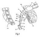
- FIG. 1is a perspective view illustrating an example of a stabilizing instrument mounted to a rail of a retractor arm according to the present invention.
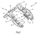
- FIG. 2is a perspective view of a retractor system including the retractor arms shown in FIG. 1 .
- FIG. 3Ais an exploded view of the components at the distal end of a stabilizing instrument according to the present invention.
- FIG. 3Bis an assembled, sectional view of the components shown in FIG. 3B, except for the distal most, foot component.
- FIG. 3Cis an exploded view of the components at the distal end of a stabilizing instrument including a slight variation of that shown in FIG. 3 A.
- FIG. 4is a partial plan view of a cable having a cable fitting mounted thereon, according to the present invention.
- FIG. 4Ais a perspective, isolated view of distal most articulating link according to the present invention.
- FIG. 4Bis a longitudinal sectional view of the link shown in FIG. 4 A.
- FIG. 4Cis an enlarged detailed view of the portion of the link identified by III in FIG. 4 B.
- FIG. 5Ais an end view of a distal surface of an adapter link according to the present invention.
- FIG. 5Bis a longitudinal sectional view of the adapter link shown in FIG. 5A, taken along line 5 B— 5 B.
- FIG. 5Cis a sectional view of the adapter link shown in FIG. 5A, taken along line 5 C— 5 C.
- FIG. 6is a perspective view of an adapter link 340 according to the present invention.
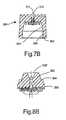
- FIG. 7Ais a perspective view of a link having a female articulating surface for a rotational joint.
- FIG. 7Bis a longitudinal sectional view of the link shown in FIG. 7 A.
- FIG. 8Ais a perspective view of a link having a male articulating surface for a rotational joint.
- FIG. 8Bis a longitudinal sectional view of the link shown in FIG. 8 A.
- FIG. 9Ais a perspective view of a distal portion of a stabilizer mount according to the present invention.
- FIG. 9Bis a bottom view of the distal portion shown in FIG. 9 A.
- FIG. 9Cis a longitudinal sectional view of the distal portion shown in FIG. 9 A.
- FIG. 10Ais a plan view of a proximal portion of a stabilizer mount according to the present invention.
- FIG. 10Bis a longitudinal sectional view of the proximal portion shown in FIG. 10A, taken along line 10 B— 10 B.
- FIG. 10Cis a plan view of a screw member according to the present invention.
- FIG. 10Dis an end view of the screw member shown in FIG. 10C as viewed from the left in FIG. 10C
- FIG. 10Eis a plan view of an anchor according to the present invention.
- FIG. 10Fis a perspective view of a stabilizer device including an optional flexible sleeve according to the present invention.
- FIG. 11is a perspective view of a knob according to the present invention.
- FIG. 12Ais a perspective view of a torque member according to the present invention.
- FIG. 12Bis an end view of the torque member shown in FIG. 12A as viewed from the left in FIG. 12 A.
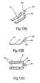
- FIG. 13Ais an example of a tissue contact member according to the present invention.
- FIG. 13Bis a side view of the tissue contact member shown in FIG. 13A
- FIG. 13Cis a bottom view of the tissue contact member shown in FIG. 13 A.
- FIG. 14Ais an exploded view of another example of a tissue contact member according to the present invention.
- FIG. 14Bis a side, assembled view of the tissue contact member shown in FIG. 14 A.
- FIG. 14Cis a sectional view of a foot or contact member of the tissue contact member shown in FIG. 14B, taken along line 14 C— 14 C.
- FIG. 14Dis a perspective view of a porous elastic pad or filter according to the present invention.
- FIG. 14Eis a bottom view of a foot or contact member of the tissue contact member shown in FIG. 14 B.
- FIG. 14Fis a sectional view of a foot or contact member of the tissue contact member shown in FIG. 14B, which is a variation of that shown in FIG. 14 C.
- FIG. 14Gis a sectional view of a foot or contact member of the tissue contact member shown in FIG. 14B, which is a variation of that shown in FIG. 14 C.
- FIG. 15Ais another example of a stabilizing device according to the present invention.
- FIG. 15Bis a sectional view of the tissue contact member shown in FIG. 15A, taken along line 15 B— 15 B.
- FIG. 16Ais a partial perspective view of a stabilization system according to the present invention.
- FIG. 16Bis a sectional view of the tissue contact members of the stabilization system shown in FIG. 16A, taken along line 16 B— 16 B.
- the instruments and methods of the present inventionmay be used for stabilization of a beating heart during a coronary artery bypass graft (CABG) procedure in which the bypass of a narrowed or blocked vessel is performed without application of cardioplegia to the patient and without cardiopulmonary bypass.
- CABGcoronary artery bypass graft
- the instruments and methodsenable the contacting of the heart and relative stabilization at and in the surrounding area of the portion of the heart contacted, to make it possible to perform delicate surgical tasks in that area.
- the instruments of the present inventionmay be used for stabilizing tissue in other applications, they are most advantageously employed in a CABG procedure in combination with a sternal retractor used to provide an opening in the chest for direct access to the heart. While it would be apparent to one of ordinary skill in the art that the present instruments could be employed separately from a retractor, they are nonetheless adapted to be mounted to a retractor to provide a desirable base of stability. However, other objects of fixation could be utilized if necessary, as known in the art.
- retractorse.g., retractor used in thoracotomy, and other rib separators
- retractorscould also serve as a base to which the present instruments could be fixed.
- the instruments of the present inventioncould be advantageously used for their stabilization capabilities in a stopped heart procedure, including procedures employing cardiopulmonary bypass.
- the present instrumentsare particularly advantageous in beating heart procedures.
- the present instrumentsmay access and stabilize the beating heart in a number of surgical contexts involving various incisions and surgical approaches to the heart as are known in the art, the instruments described herein are most advantageously employed in CABG procedures where the heart is accessed through only one or two minimally invasive incisions in the chest. Particularly, methods involving a sternal retractor are described.
- LIMAleft internal mammary artery
- LADleft anterior descending artery
- Another common procedureinvolves anastomosing a saphenous vein graft proximally to the aorta and distally to a target artery, post blockage location.
- the anastomosis procedure in either caseis a delicate and exacting procedure which requires the installation of very fine sutures around the entire perimeter of the source vessel or graft to attach it to the target vessel in a manner that is substantially leak-proof, for the immediate commencement of delivery of blood to the heart via the surgically altered pathway achieved by the procedure.
- Tissue stabilizerswhich provide superior engagement with the surface of the heart.
- Tissue stabilizers according to the present inventionmay have one or more stabilizer feet, which are adjustable as to the orientation of their features which are used to contact the tissue surface, e.g., the surface of the heart.
- stabilizer feetmay be employed and are described in detail below.
- an exemplary stabilizer 10is illustrated in FIG. 1 and is shown mounted to a removable blade portion 110 of a sternal retractor 100 (FIG. 2 ). As shown in FIGS. 1 and 2, the stabilizer 10 is adapted to be mounted to a retractor assembly 100 for performing a mid-sternal surgical procedure on the beating heart, although the present invention is not limited to such an application, as described above.
- Retractor assembly 100generally includes a pair of opposing blades 110 adapted to engage opposite sides of a sternal incision, or other incision, and a drive mechanism 112 constructed to force the blades 110 apart, thereby driving an opening in the sternum.
- the drive mechanism 112the sternum may thus be spread to the desired opening, thus providing the desired access and direct visualization of the thoracic cavity.
- the heartmay be positioned or oriented to best present the target vessels for anastomosis.
- This positioningmay be established, for example, through the strategic placement and tensioning of sutures in the pericardial sac, by appropriately placing the patient in the Trendlenburg position, or by using a heart positioner including a strap or pad or other device, such as a Guidant XPOSETM device, available from Guidant Corp., Cupertino, Calif., for example.
- a Guidant XPOSETM deviceavailable from Guidant Corp., Cupertino, Calif., for example.
- the stabilizer assembly 10having been mounted to the retractor assembly 100 is manipulated so as to bring at least one component of the stabilizer assembly 10 into contact with the beating heart adjacent the target site of the anastomosis.
- the surgeontypically applies a stabilizing force to the beating heart via the stabilizer assembly 10 until the desired stabilization if attained, and secures the stabilizer assembly in a fixed orientation to maintain the stabilizing force against the beating heart.
- the positioning and fixation of the stabilizer assembly 10substantially eliminates movement of the heart in the area of the anastomosis, thereby facilitating the surgeon's placement of sutures and related procedural requirements in performing the anastomosis (or other surgical procedure).
- the stabilizer assembly 10is released to enable it to be flexibly moved away from contact with the heart.
- the retractor assembly 100 shown in FIG. 2may be used in mid-sternotomy procedures, together with a stabilizer assembly 10 according to the present invention, but is shown for purposes of example only. As noted above, stabilizer assemblies according to the present invention may be used with other types of retractors, or even without a retractor.
- Retractor assembly 100includes a drive mechanism 112 to which are mounted a pair of opposing retractor blades 110 adapted for insertion into an incision and for engaging opposite sides of the incision. In the example shown, retractor blades 110 are removable from the drive mechanism 112 , although this feature is not required for operation with a stabilizer assembly 10 according to the present invention.
- the opposing blades 110When the heart is accessed by way of an incision through all or a portion of the sternum, the opposing blades 110 may be inserted into the incision and driven apart by operation of the drive mechanism 112 to create an opening and working space for operating on the heart.
- the drive mechanism 112is constructed to spread the opposing blades apart in a generally planar movement, although the separating motion may also have a significant curvilinear or angular component in addition.
- the blades 110may each have one or more channels or engaging members 118 adapted to engage opposite sides of an access incision. Different sizes of blades are available so as to optimize the engagement of the retractor assembly with various sizes and shapes of sternums.
- Activation of the drive mechanism 112force apart the first and second platform blades 110 thereby causing engaging members 118 to correspondingly force the incision open to provide access to the desired surgical site.
- engaging members 118are adapted to engage each side of the incised sternum to reliably hold and engage the sternum as the sternum is forced open to expose the thoracic cavity and ultimately the heart.
- FIG. 2shows a ratchet or rack arrangement, as is generally known in the art.
- Rotation of the handle on handle assembly 124facilitates movement of a moveable housing 124 relative to the bar 115 of the drive mechanism 112 , by engaging a pinion (not shown, but mounted to the handle) with the rack teeth 111 on the bar 115 in a cogging manner.
- This effectively moves the blade 110that is attached to or mounted on the movable housing 124 , toward or away from the other blade 10 that is attached to or mounted on a fixed housing 121 which does not move relative to the bar 115 .
- platform blades 110may incorporate a wide variety of additional features which enhance the performance of the retractor system.
- one or both bladesmay have mounting features to which stabilizer 10 , and various other instruments used during the procedure, can be secured.
- the engaging features 118 which engage the sternumare preferably part of a unitary platform blade structure which also includes mounting features to which a stabilizer and other instruments can be mounted and secured. Since the mounting features and the sternal engaging features are part of the same component, there is no mechanical connection between the two, and the stability of an attached instrument against the forces of a beating heart is greatly improved.
- the first and second platform blades 110include mount features in the form of rails 160 .
- a mount featuremay also be included on the rack bar 115 .
- the rails 160allow stabilizer 10 (and other instruments) to be positioned at any desired location along the operable length of either rail.
- the rails 160may be oriented substantially perpendicular to the direction of separation of the blades 110 , or in a more curvilinear fashion.
- the rails 160extend upwardly from the bodies of the platform blades 110 , although they may be formed alternatively as recessed features or in another configuration.
- the upwardly extending configurationsare adapted to connect with the stabilizers having connecting features as shown in the examples.
- Stabilizer 10is a multi-jointed device which provides the flexibility needed to reach less direct surfaces of the heart from the incision opening. Additionally, stabilizer 10 is extremely low profile to maximize the amount of free space available in the opening for use by the surgeon.
- stabilizer 10includes a heart contact member 20 adapted to contact the heart adjacent the site desired to be stabilized.
- the contact member 20may include a pair of feet or contact members 22 as shown in FIG. 1, which may be substantially planar, or slightly curved to conform to the shape of the heart, or one or more may have a non-conforming curve to establish a contact between only a portion of the contact member 20 and the beating heart.
- the shape of the feet 22 and the contact member 20may be varied depending on the clinical assessment by the surgeon, the design of the remainder of the stabilizer 10 , and/or the design of other instruments to be used to complete the anastomosis.
- Various examples of contact memberswill be detailed herein as the description proceeds.
- Stabilizer 10further includes a highly maneuverable arm 30 which connects the contact member 20 through a base member 40 to a tightening mechanism 50 at the proximal end of the device.
- the maneuverable arm 30includes multiple articulating joints which enable the contact member 20 to be positioned and set at a wide variety of positions, virtually enabling the contact member to be used for any target site in performing anastomoses according to the present invention.
- the multiplicity of articulating jointsallow versatile positioning, and a cable 288 which runs through each of the joints and interconnects them with the tightening mechanism 50 , may be tensioned to freeze the selected orientation of the device in a rigid configuration. In this way, the contact member 20 can be maintained at the desired orientation to provide stabilization to that portion of the heart tissue with which it makes contact, as well as the immediately surrounding area.
- FIG. 3Aan exploded view of the components at the distal end of stabilizing instrument 10 are shown which connect the maneuverable arm 30 to the contact member 20 .
- the distal most articulating member 310 of the maneuverable arm 30includes a cavity 312 (see FIG. 3B) which opens to the distal end of the articulating member 310 and is adapted to at least partially receive coupling members 260 , 280 and 290 , which are described below.
- a socket member 240having an outside diameter of about 0.375 inches in this example, caps the distal end of the stabilizer 10 and is mated to the distal most articulating member 310 via coupling members 260 , 280 and 290 , in concert with the tensioning cable which runs through the stabilizer.
- Socket member 240includes an opening 242 , which is dimensioned to freely receive the ball portion 222 of a connecting element 220 to which contact member 20 is fixed. Socket member 240 further includes a slot 244 dimensioned to receive stem 224 of connecting element 200 , allowing it to slide freely in the slot 244 while at the same time preventing ball portion 222 from passing therethrough. A proximal opening 246 is provided in the socket member and dimensioned to receive at least a portion of coupling members 260 , 280 and 290 .
- Coupling member 260may be a socket cap which is received within the proximal opening.
- Socket cap 260includes a base or cap portion 262 dimensioned to abut ball portion 222 and maintain it in its position in the socket member 240 .
- the cap portionhas a substantially planar bottom surface with a circular opening dimensioned to ride against the sphericity of the ball portion 222 .
- other configurations of the bottom surfaceare contemplated which would accomplish the same function, e.g., the ability to apply force against the ball portion 222 and maintain the ball portion within the socket member 240 , while also allowing the ball portion to rotate.
- the cap portion 262upon increased application of force, has the ability to lock the ball portion and prevent it from rotating.
- the outer surface of the socket cap 260is substantially cylindrical and adapted to slidably and rotatably fit within the cavity of the coupling member 240 introduced by the proximal opening 246 . This allows rotation of the contact member about the longitudinal axis of the maneuverable arm when the stabilizer is in a non-rigid state.
- the proximal portion of the socket cap 260includes driving surfaces 264 adapted to abut against the distal most articulating member 310 and transmit force against the ball portion 222 via cap portion 262 when the cable is tensioned. In the example shown in FIG. 3A, driving surfaces 264 are located on tabs 266 which are dimensioned to be received in slots 314 in the distal most articulating member 310 .
- the socket member 240may be pulled in a direction away from the distal most articulating member 310 by a sufficient distance to allow ball portion 222 to be extracted through opening 242 , for example to change the setup by replacing the existing contact member 20 with a different one.
- a changemay be made between contact members to choose a different design or configuration, or even to change to one which operates on a different principle.
- a change from a mechanical contact member, which operates by applying physical pressure against the beating heart tissuemay be replaced with a negative pressure contact member, which engages the heart by vacuum.
- any of the contact members described hereincould be exchanged for operation in the stabilizer 10 described.
- other known contact memberscould be used or adapted to be used by those of ordinary skill in the art. This interchangeability is made possible by the notches 314 which allow separation of the tabs 266 therefrom.
- the notches 314may be replaced by enclosed holes 314 ′ (see FIG. 3C) which maintain the capture of tabs 266 even when the tension is fully relieved in the stabilizer 10 .
- the socket member 240cannot be separated from the distal most articulating member 310 ′ and coupling members 260 , 280 and 290 by a sufficient distance to remove ball portion 222 through opening 242 (unless a shim within the mount is removed as described below). While this arrangement eliminates the ability to easily interchange contact members, it has the advantage of ensuring that the contact member will not become accidentally disengaged or removed, regardless of the amount of tension (or lack thereof) in the stabilizer 10 .
- the socket cap 260further includes recessed or open portions 266 dimensioned to receive the arms 292 of coupling member 290 .
- the recessed portionsare continuous over the length of the socket cap 260 and are also defined along the perimeter of the cap portion 262 .
- the arms 292interfit with the socket cap and are continuous with the outer perimeter thereof to form a cylindrical surface for rotating against the socket member 240 .
- the interior surface of socket member 240is undercut near the proximal end to form an annular groove 248 that extends around the interior circumference of the proximal end portion and underlies a lip 248 formed thereby.
- tines 294which extend outwardly from arms 292 at the distal end of the arms, engage the groove 248 and are prevented from being withdrawn from the socket member 240 by lip 247 . Because the lip 247 and groove 248 extend around the entire inner circumference of the socket member 240 , coupling member 290 is free to rotate with socket cap 260 in an unlocked configuration of the stabilizer 10 .
- the outside ends of the tines 294are preferably chamfered or beveled 294 a to ease the insertion of the coupling member 290 into the socket member 240 .
- the cavity 312 in member 310is dimensioned to slidably receive at least the proximal portions of coupling members 260 and 290 with a close fit. Because the tabs 266 engage with either slots 314 or holes 314 ′, the coupling members 260 and 290 do not rotate with respect to member 310 , but only with respect to socket member 240 .
- Coupling member 290is provided with an abutment surface 296 which is adapted to abut against the upper surface 312 t that defines the top of cavity 312 .
- a central opening 298is provided through the abutment surface and proximal end of the coupling member to allow the tensioning cable to pass therethrough.
- a cable fitting 280is provided as a part of the coupling assembly, and includes an enlarged ball-shaped or other shape stop portion 282 which has an abutment surface 284 adapted to abut against coupling member 292 to apply a force thereto when the cable is drawn up thereagainst.
- Cable fitting 280also includes a hole or passage 286 passing centrally and longitudinally therethrough, for passage of the cable therethrough.
- Each of the coupling components 260 , 280 and 290 , as well as the socket member 240 and connecting element 220may be made of a machined biocompatible metal, such as stainless steel, or may be molded, such as by metal injection molding, for example. Alternative metals which are biocompatible and meet the strength requirements for this application may also be employed.
- cable 288is preferably a multi-strand metallic cable made from 300 series stainless steel in a 7 ⁇ 7 configuration (seven strands in each of seven bundles), but may be made of another high strength biocompatible material which would be suitable for such purposes, e.g., Kevlar, titanium and the like.
- the cableshould preferably have a tensile breaking strength of at least about 470 psi.
- the cable 288is assembled with the cable fitting 280 by passing the cable 288 through passage 286 and then welding, soldering, swaging, adhering, crimping or otherwise securing the cable fitting 280 to the cable in a manner to withstand tensile forces up to about 470 psi.
- 470 psiis a value that is used for the particular embodiment presently being described, and that this value may vary depending upon variation of size or other parameters used in each particular stabilizer device.
- the distal ends 289 of the componentsmay be made flush by grinding for example.
- the proximal end 287is electrocut to length, which, in this example is about twelve inches ⁇ a quarter of an inch.
- the maneuverable arm 30comprises a plurality of articulating members or links.
- Each linkincludes a hole passing through its center and long its longitudinal axis, to provide a passageway for cable 288 which passes through each link.
- the linksmay be made from a high strength, high rigidity plastic such as a rigid glass-filled polyurethane, for example, or other acceptable high rigidity biocompatible plastics known in the art.
- the linksmay be alternately arranged such that links formed of rigid glass-filled polyurethane alternate with links formed of polycarbonate with Teflon and glass fill, for example.
- the links of the maneuverable arm 30are formed in groups having progressively stepped down outer diameters, where the distal most link 310 has the smallest diameter at its distal end, and the proximal most links have the largest diameters, with intermediate diameters existing between the two ends.
- This decreasing diameter profilemaximizes the amount of free or working space available to the surgeon at the distal or working end of the device, while maintaining additional friction capability toward the proximal end to ensure a sufficient overall rigidity of the device upon tightening the cable.
- FIG. 4Ais a perspective, isolated view of distal most articulating link 310 .
- the distal portion 316 of link 310has an outside diameter of about 0.400 inches in this example where it forms a rotational joint with socket member 240 such that, in an unfixed state, the socket member 240 is free to rotate about the longitudinal axis 3101 of the link 310 .
- Link 310includes a central transitional portion 317 that transitions the link to the larger diameter portion 318 at the proximal end thereof.
- the outer diameter of portion 318 in this exampleis about 0.500 inches, which is substantially matched to the outside diameter of articulating link 320 with which it articulates.
- the articulating joint which is formed between links 310 and 320is formed by a series of “V-trenches” 32 and teeth 34 aligned parallel across the faces of the links that articulate with one another.
- the articulating faceis concave
- the distal articulating face of link 320 that interfaces link 310is convex.
- the surfacesare designed to conform to one another, with the V-trenches 32 of link 310 meshing with the teeth (or ridges) 34 of the distal surface of link 320 , and the V-trenches 32 of the distal surface of link 320 receiving and meshing with the teeth 34 of link 310 .
- both surfaceshave the same (although inverse) degree of curvature, they articulate smoothly in the direction of the V-trenches, gliding smoothly in a single plane of rotation only, when the device is in an unrestricted, or untensioned state.
- frictional forces between the teeth and the V-trenchesincrease making it increasingly difficult to articulate the joining surfaces, until eventually the two pieces become fixed with respect to one another.
- This fixationcan occur at any desired relative positioning between the two links within the range of motion provided by the joint. This is the basis for the ability to fix the device in any desired configuration.
- the trenches 32not only provide a track along which the teeth 34 are guided for rotational articulation of the joint in a plane, but they must have a sufficient aspect ratio and angulation to effect a progressive development of friction as the teeth sink lower into the trenches under compression.
- Aspect ratiois defined here as a ratio of the depth (or height) of the trench over the average width of the trench.
- the aspect ratio of the trenchesshould be at least about 1:2 or greater.
- the aspect ratio of the teethshould also be at least about 1:2 or greater. In the examples shown, the aspect ratio is closer to 1:1.
- the trenchesfor example, may be about 0.055′′ deep (see FIG. 4C, 34 h ) and about 0.048′′ average width.
- the angulation of the each side of the trench with respect to a normal line intersecting the bottom of the trenchmay be about 10 to 20 degrees and, in the example shown is about 17 ⁇ 1 degrees. Because teeth 34 are angled in a V-shape, in the same way that the V-trenches 32 are configured, as a tooth 34 is forced into a trench 32 , the frictional forces increase geometrically due to the increase in width on both sides of the tooth 34 a and 34 b that contacts sides of V-trench 32 a and 32 b at any given depth.
- any outward give or compliance of a V-trenchis counteracted an equal, but opposing force developed in an adjacent V-trench undergoing the same compressive forces against a similarly dimensioned tooth.
- the V-trench designprovides continuously articulating surfaces between the teeth and the trenches and has been found to provide greatly superior frictional results, as compared to existing ball and socket configurations and modified ball and socket configurations, when equal amounts of compressive force are applied to each type of articulating joint design.
- the link 310includes four V-trenches 32 alternating with five teeth 34 , although it would be known to those of ordinary skill in the art that these numbers could be varied.
- the peak-to-peak distance 35 between teeth 34is about 0.100 inches in the example shown (FIG. 4 C).
- the height 34 h of a tooth 34may be about 0.050 inches and the angle formed by the walls 32 a and 32 b of a trench 32 (or by walls 34 a and 34 b of a tooth 34 ) may be about thirty degrees, plus or minus about ten degrees.
- the width of a tooth, at the top surface 34 cmay be about 0.050 inches.
- the link 310may be tapered to form a conical pathway 313 to enhance the flexibility of the maneuverable arm 30 .
- the conical pathwayassists the cable 288 in bending, especially under extreme angles, by providing a pathway which is more curved when a series of these pathways are assembled as in the case of an assembly of links.
- Angle 313 a formed by the wall of the pathway 313may also be about thirty degrees, plus or minus about ten degrees.
- a second link 320is assembled on the proximal end of the link 320 described above.
- the links 320are substantially identical and each have substantially the same outside diameter along the entire length thereof, the outside diameter being about 0.500 inches.
- the proximal surface of each link 320is substantially identical to the proximal surface of the link 310 .
- the distal surface of each link 320has a series of V-trenches 32 and teeth 34 adapted to mesh with a proximal surface of a link 320 or link 310 .
- the distal surfacehas five trenches 32 alternating with four teeth 34 , for example, to provide a topography adapted to mate with the five teeth 34 and four trenches of the proximal surface of a link 310 or link 320 , for example.
- thisis merely an example and the configurations may be switched between the two surfaces.
- the inventionlimited to only a 5-4 configuration as more or fewer teeth and trenches may be formed in a series on a surface.
- the outside diameters of the linksmay also be different from that described.
- a smaller maneuverable armcan be made using lengths having outside diameters of 0.400, 0.500, 0.600 and 0.700 inches, respectively.
- a larger armcould be produced by scaling up the link sizes, respectively.
- An adapter link 330is assembled on top of the second link 320 as shown in FIG. 1 .
- Adapter link 330has a distal portion 332 (see FIG. 5B) which has substantially the same outer diameter as the outer diameter of link 320 (in this example, about 0.500 inches).
- the distal surface of adapter link 330is essentially the same as the distal surface of a link 320 as described above, and is shown here in FIG. 5 A.
- Outlying the series of V-trenches 32 and teeth 34are a pair of side walls 33 which are very similar to teeth 34 but only interface with a trench on one side thereof. Nonetheless the side walls 33 contribute to the balancing of side forces between the trenches and contribute to the articulating function of the joint overall.
- An angular gap or section 336is formed in the distal face and central tooth 34 to facilitate the bending of the cable 288 (see FIG. 5 C).
- the angle formed by gap 336is about sixty degrees plus or minus about five degrees and is centered on the longitudinal axis 3301 of the link 330 .
- the flexibility of each articulating V-trench jointis about fifteen degrees in either direction away from the longitudinal axis 3301 .
- a transitional portion 337 of the adapter link 330connects the smaller diameter distal portion 332 to the larger diameter proximal portion 334 .
- the distal portionhas an outside diameter of about 0.600 inches.
- the distal articulating surfaceis formed much in the same manner as the distal articulating surfaces of the smaller links described earlier, preferably with the same degree of concavity, although it could be varied.
- the V-trenches 32 and teeth 34are also preferably of the same height, width and pitch (i.e., angle of walls) as those described with regard to the smaller links 310 and 320 , although the length of these features is necessarily longer so as to span the larger section presented by this surface.
- a conical pathway 313is provided to enhance the flexibility of the maneuverable arm 30 .
- the overall length of adapter link 330measure from proximal end to distal end is about 0.525 inches in this example.
- An additional adapter link 340may be assembled over adapter link 330 as shown in FIG. 1 .
- Adapter link 340is constructed essentially the same as adapter link 330 , but is scaled larger. That is, the distal portion has an outside diameter of about 0.600 inches and an articulating surface that is convex and adapted to mesh with the proximal articulating surface of the link 330 .
- the V-trenches 32 and teeth 34are also preferably of the same height, width and pitch (i.e., angle of walls) as all others previously described with regard to the smaller links.
- the proximal portion 344has an outside diameter of about 0.700 inches and therefor the length of the trenches and teeth are necessarily longer so as to span the larger section presented by this surface.
- the articulating surfacesprovide excellent high friction locking surfaces when the links are compressed together, which allows the design of a smaller and lower profile device than has been known previously. Also, since a significantly lower compression force is effective (e.g., a tensioning force on cable 288 of only about four hundred pounds results in a stiffness of the device equally to that requiring a one thousand pound force in some prior art devices), the tightening mechanism can be made smaller, enabling a lower profile of the overall device. Since the V-trench articulating surfaces allow rotation in only one dimension (i.e., rotation in a single plane), at least one rotational joint 355 (FIG. 1) is provided with a plane of rotation normal to the plane of rotation of an adjacent V-trench joint.
- Rotational joint 355is formed between female link 350 and male link 360 .
- the distal portion of maneuverable armthus far described may be flexed in any plane of rotation which is coaxial with the longitudinal axis of the rotational joint, since the longitudinal axis also establishes the center of rotation of the rotational joint 355 . This greatly enhances the flexibility and versatility of the stabilizer, as to the locations that it can be positioned to address.
- Female link 350is about 0.650 inches long in this example and has an outside diameter of about 0.700 inches.
- the distal articulating surfaceis adapted to mesh with and articulate with the proximal surface of the adapter link 340 .
- a central opening 311is provided in the link 350 , the same as all previously described links, and is tapered conically 313 to enhance the flexibility of the cable 288 and maneuverable arm 30 overall.
- the proximal end of link 350form a flat annulus 352 which is adapted to interface with a like surface at the distal surface of the male link 360 , described below.
- a opening in the distal endprovides a race 354 against which the male portion of the joint articulates during rotation. Race 354 is shown as cylindrical 354 and then conically tapered 354 ′, but may be completely conically tapered.
- Male link 360includes male bearing portion 362 which is adapted to rotate in race 354 .
- the conical tapering of race 354 and the conical taper of male bearing portion 364allow a finite amount of flexing between the two components such that the rotation joint therebetween will still function without binding or popping out of joint even when the maneuverable arm is maximally flexed.
- a flat annular surface 364is provided at the base of the male bearing portion 362 and is adapted to interface with and rotate against annular surface 352 , in a relaxed state. Further, the compression of these two annular surfaces together acts to increase the friction resistance between the male and female links, thereby preventing rotation.
- male link 360also includes a central opening 311 and conical taper 313 in the proximal portion, as well as about a thirty degree conical taper 336 ′ to enhance the flexibility of the cable 288 and maneuverability of the maneuverable arm 30 .
- Male link 360tapers to a larger proximal portion 366 having an outside diameter of about 0.800 inches.
- the proximal surfaceis concave with teeth 34 and V-trenches which may be manufactured to the same dimensions (except length) and standards as those previously described.
- each of the large linksis substantially identical, only one will be described here to avoid redundancy.
- Each large link 370has a substantially consistent outside diameter over the length thereof, which is about 0.800 inches.
- the constructionis essentially the same as described with regard to links 320 , but scaled up to size. Therefor, each link 370 provides substantially more surface area against which the surfaces articulate, as well as develop friction under compression. In this way, the large links develop a great deal of rigidity and fixing strength when the cable is tensioned.
- a large diameter female link 380interfaces the fourth large link 370 .
- Female link 380is constructed essentially the same as female link 350 , but is scaled up to a size having about a 0.800 inch outside diameter.
- the distal endincludes V-trenches 32 and teeth 34 which mate with the corresponding V-trenches and teeth in the proximal end surface of link 370 .
- the distal endincludes a flat annular surface and a race which are formed the same as 352 and 354 , only of slightly larger dimension.
- Large female link 380forms a second rotational joint 385 with the distal portion of mount 40 .
- FIG. 9Ais a perspective view of the distal portion 40 a of mount 40 .
- the distal end of distal portion 40 aextends a male bearing portion 402 male bearing portion which is adapted to rotate in the race of the large diameter female link 380 , or, is actually the case when mount 40 is fixed to a stationary object such as a retractor, to allow the race of the large diameter female link 380 to rotate on the male bearing portion 402 .
- the conical tapering of the race and the conical taper of male bearing portion 402allow a finite amount of flexing between the two components such that the rotation joint therebetween will still function without binding or popping out of joint even when the maneuverable arm is maximally flexed.
- a flat annular surface 404is provided at the base of the male bearing portion 402 and is adapted to interface with and facilitate rotation of the annular surface of the large female link 380 , in a relaxed state. Further, the compression of these two annular surfaces together acts to increase the friction resistance between the male and female links, thereby preventing rotation. Additionally, the conical surface of the male bearing portion 402 is forced into the race of the large female link 380 upon tightening of the device, thereby frictionally locking the joint.
- the second rotational joint 385is provided with a plane of rotation normal to the longitudinal axis of the distal portion 40 a .
- the entire maneuverable arm 30may be flexed in any plane of rotation which is coaxial with the longitudinal axis of the rotational joint, which is also the longitudinal axis of the distal portion 40 a , since the longitudinal axis also establishes the center of rotation of the rotational joint 385 .
- the portion of the maneuverable arm 30 that is distal to rotational joint 355may be flexed in a plane of rotation which is coaxial with the longitudinal axis, but different from the plane of flexation of the portion of the maneuverable arm that is proximal to the rotational joint 355 .
- Mount 40may be molded of a high strength and highly rigid composite polymeric material such as polycarbonate with Teflon and glass fill, for example having about 10 percent Teflon, and 20 percent glass fiber fill, with the percentages being weight percentages. Alternatively, other materials such as CCP, polyurethane, etc. could be employed for this purpose. As an alternative to molding, it would also be possible to machine these components. Because of the simplicity of the design of mount 40 , it can be made to be extremely low profile, thereby taking up less space at the location of mounting, and more importantly, positioning the entire stabilizer very close to the stationary mounting site and minimizing the amount of space that it extends into the surgical site.
- mount 40An important function of mount 40 is to securely fix stabilizer 10 to a relatively immobile object, such as a sternal retractor, so as to maintain the stabilizer in a fixed position relative to the beating heart.
- the stabilizeritself can be made rigid through the mechanisms described herein, and could possibly be hand operated, but the stabilization process is more effective and requires fewer hands in the vicinity of the surgical site if the stabilizer can be anchored to an immovable object.
- Mount 40is adapted to be clamped to an appropriate rail, such as on a sternal retractor, for example, and secured by rail grips 406 and 410 .
- Distal and proximal portions 40 a and 40 bare joined by a hinge formed by passing a hinge pin (not shown) through hinge pin receptacles 412 and 414 .
- the hinge pinis a straight metallic shaft which is press fit into the pin receptacles.
- the hinge pinis preferably formed of medical grade stainless steel or an alternative biocompatible metal.
- the hinge jointallows the portions 40 a and 40 b to be pivoted toward and away from one another about the hinge pin. When the portions 40 a and 40 b are pivoted away from one another, rail grips 406 and 410 also move away from one another. This position is used for releasing the mount from a rail and for positioning the mount over the rail prior to engaging the mount to it.
- Distal portion 40 ahas a living hinge 416 , located directly beneath hinge receptacle 412 , which is adapted to receive and engage a second hinge pin 418 mounted in proximal portion 40 b beneath hinge receptacles 414 .
- the neck 420 of living hinge 416defines a slot having a dimension slightly smaller than the outside diameter of second hinge pin 418 .
- second hinge pin 418contacts the sides of neck 420 , thereby exercising living hinge 416 by forcing neck 420 open to allow second hinge pin 418 to pass by and engage in hinge receptacle 422 .
- Hinge receptacle 422is dimensioned slightly larger than the outside diameter of second hinge pin 418 .
- Second hinge pin 418seats in hinge receptacle 422 , thereby allowing living hinge 416 to relax and neck 420 to return to its original dimension and locking hinge pin 418 in.
- This entire operationresembles a “snap fit” and securely fixes the portions 40 a and 40 b in approximation with one another.
- rail grips 406 and 410are brought into a fixed configuration, gripping both sides of the rail on which the mount 40 is secured.
- the release operationis just as simple, where the mount portions can be simply “snapped” open and pivoted away from one another to dismount the stabilizer 10 from a rail.
- the fixed position of the mount 40may be designed to completely secure the stabilizer 10 to a rail, or it may be designed to clamp the rail snugly, thereby stabilizing the device 10 , while still allowing the mount to be slid along the rail (under a significant amount of friction) to reposition it.
- Mount 40is provided with a large opening 408 which funnels down to a smaller passageway 424 through which cable 288 is passed through upon assembly of the maneuverable arm 30 .
- coupling member 290is assembled over cable 288 by threading it over the proximal, or free end of the cable and sliding it to the end fixed to the cable fitting 280 to abut stop portion 282 .
- Socket cap 260is then placed over the distal end of the cable fitting 280 and interfit with coupling member 290 , thereby surrounding stop portion 282 together with arms 292 .
- Socket member 240is then snap fit over the coupling assembly, thereby engaging tines 294 with lip 247 , after which links can begin to be added.
- the distal most link 310is assembled over the proximal end of the cable and slid down to engage driving surfaces 264 of socket cap 260 . If the link 310 has notches 314 , the driving surfaces 264 simply engage notches 314 and must be maintained pressed into position or they may fall out of position if no compression is maintained. If the link 310 ′ has holes 314 ′, then the driving surfaces may snap into position and be secured there.
- the remainder of the links, 320 , 330 , 340 , 350 , 360 , 370 and 380are then assembled in order by simply sliding them from the proximal end of the cable down into position over one another and oriented so that the V-trenches and teeth engage with one another on interfacing surfaces.
- a safety crimpis then formed over the cable 288 proximally of the large female link 380 .
- the safety crimpis formed by placing a small tubular piece of ductile metal over the cable and then crimping or deforming the ductile metal so that it is anchored in a desired position on the cable.
- the deformed metalis too large to pass through the central opening in the large female link 380 and thus serves as a precautionary measure to maintain all of the links on the cable, should there be a failure in the vicinity of the mount or proximal to the mount.
- the maneuverable arm 30now having been loosely preliminarily assembled, the proximal end of cable 288 is passed through large opening 408 in distal portion 40 a of mount 40 and through opening 424 whereby distal portion 40 a is positioned loosely up against large female link 380 .
- An open channel 426is provided in the underside of distal portion 40 a proximally of opening 424 , which allows access to cable 288 .
- An additional cable fitting(not shown), similar to the safety crimp, but longer to increase the amount of friction, is slid over the proximal end of cable 288 and positioned adjacent opening 424 where it is securely crimped.
- the second hinge pinhaving been secured into place in the proximal portion 40 b , the proximal portion 40 b is then assembled with the distal portion 40 a , after passing the cable through the central opening of proximal portion.
- Assembly of the mount portionsis made by aligning hinge receptacles 412 and 414 , and press fitting the first hinge pin therein.
- a biasing member 432such as a coil spring for example, and screw 440 are next inserted into the proximal opening 430 of proximal portion 40 b at the same time passing cable 288 through the central opening of the biasing member and central opening 442 that passes through screw 440 .
- Screw 440is inserted head first, and opening 430 is configured so as to prevent rotation of the screw 440 with respect to the mount 40 once the screw 440 has been inserted.
- opening 430is configured so as to prevent rotation of the screw 440 with respect to the mount 40 once the screw 440 has been inserted.
- the version shown in FIG. 10Dhas a hexagonal head 444 and opening 430 has a hexagonal cross section which allows the head 444 to be slid into opening 430 , but prevents head 444 from rotating once it has been slid into opening 430 .
- the shape of the head 444 and 430may be varied, as would be apparent to those of ordinary skill in the art, so long as the opening allows the head to be slid in and then prevents rotation of the head once in position.
- Biasing member 432ensures that the proximal portion of the screw 440 and the threads 452 surrounding it are maintained in a position that extends from mount portion 40 b to ensured that a torque member (described below) can be positively threaded thereto, in a repeatable and reliable fashion.
- An enlarged opening 446is provided in the proximal end of the screw 440 which is dimensioned to receive an anchor 450 (FIG. 10E) that is slid over the cable 288 and crimped into place to secure the screw 440 in position and to further lock the assembly. Opening 446 tapers to join opening 442 and thereby forms an abutment surface 448 against which the anchor 450 is secured.
- Anchor 450is preferably formed of a malleable metal such as brass or aluminum, for example, and screw 440 is preferably metal, such as metal injection molded 316 series stainless steel, for example. Threads 452 may be lubricated with a grease having a vegetable oil, silicone or other biocompatible base, to smooth the tightening operation, described below.
- a flexible sleeve 460may be positioned over the links of the maneuverable arm 330 , as shown in FIG. 10F, if desired.
- the sleevemay, although does not necessarily need to, be formed in two parts such that a distal part is slid over the distal portion of the arm 330 where it is attached to the distal most articulating member at 460 a and at the distal portion of the intermediate rotational joint at 460 b .
- the proximal part of the sleeve 460is fitted over the proximal portion of the arm 330 where it is attached to the proximal portion of the intermediate rotational joint at 460 c and at the distal portion of the rotational joint at the proximal end of arm 330 at 460 d.
- the sleevecould be formed of an elastomer such as silicone or dip molded PVC, for example, it has been found that the flexibility of the links about an axis perpendicular to the longitudinal axis of the maneuverable arm 330 may be limited by such a sleeve, although rotation about the longitudinal axis is not so limited. It has been found that superior results may be achieved by using a material that has more axes of elasticity, such as a knitted LYCRA® or SPANDEX material having a four or six way stretch. Such a sleeve 460 does not preload the maneuverable arm significantly so as to restrict its flexibility in either of the motions discussed above.
- any of the sleeve materialsserves the function of further ensuring that no foreign materials (e.g., sutures, surgeon's gloves, etc.) will be trapped or snagged in any of the articulating joints of the maneuverable arm 330 .
- An additional advantage of a sleeve 460is that it provides an extra degree of integrity to the maneuverable arm 330 , helping maintain each of the links in its intended position. Further, if there should be a failure in the cable 288 or other factor causing disintegration of the device, the sleeve 460 would prevent loss of links and maintain the integrity of the device.
- the torque member 520is preferably formed of a hard polymer material such as polycarbonate.
- Torque member 520is threaded internally with threads 522 dimensioned to mate with the external threads 452 on the shaft of screw 440 .
- Threads 522 and 452must be strong enough to withstand the tensile forces that are applied to cable 288 when they are threaded together. The threads must therefor be strong enough to withstand tensile forces of at least 470 psi in the example described above.
- Torque member 520further includes a torque limiter formed by fins 524 .
- Fins 524are integrally molded of polycarbonate with torque member 520 , and are placed so as to engage trenches 562 in knob 560 when torque member 520 is slid into knob 520 .
- Fins 524are angled with respect to the body of torque member 520 in a clockwise direction when viewed from the proximal end of torque member 520 ,as shown in FIG. 12 A.
- Knob 560includes tabs 564 which extend from ribs 566 that separate the trenches 562 .
- Tabs 564are configured to lock into circumferential annular trench 430 on the proximal portion of proximal mount portion 40 b in a snap fit manner. That is, the inner diameter of a circle formed by connecting the tops of tabs 564 is smaller than the outer diameter of the proximal end 432 of mount portion 40 b .
- tabs 564deflect or give somewhat to pass by the proximal end and snap into place in circumferential trench 430 , which has an outside diameter slightly smaller than the inside diameter formed by tabs 564 .
- Knob 560has an internal cup or cylinder 568 extending from the center of the proximal end inside of knob 560 .
- Cup 568is a hollow cylinder dimensioned to receive a spacer 526 that makes up the proximal end portion of torque member 520 .
- Spacer 526maintains threads 522 in alignment with threads 452 on screw 440 when knob 560 is snapped onto the mount 40 .
- Threads 522are self starting and will engage threads 452 when knob 560 is turned in a clockwise direction. When knob 560 is turned a sufficient amount in the counterclockwise direction, threads 522 disengage from threads 452 to ensure that no residual tension is left on cable 288 so that the maximum flexibility of maneuverable arm 30 is available.
- cup 568maintains threads 522 in alignment with threads 452 to ensure that torque member 520 does not become cross threaded when knob 560 is turned clockwise.
- Knob 560includes four extensions 570 radially extending from equally circumferentially spaced locations on the proximal portion of knob 560 .
- the present inventionis not limited to the use of four extensions, as more or fewer extensions may be used and still achieve the desired results.
- Extensions 570not only provide a convenient non-slip handle to be grasped by the hand of an operator, but also provide additional mechanical advantage to apply torque for tensioning cable 288 . As noted above, because of the efficiency of the frictional surfaces provided by the V-trench and tooth design on the articulating links, less force is needed to sufficiently rigidity the stabilizer than that required by prior art designs.
- extensions 570can be made to extend by a significantly smaller distance. This is important because it allows the entire device 10 , and particularly the mount 40 to be made to assume an extremely low profile and thereby provide the surgeon with more working space.
- Knob 560may be made from the same materials as the links.
- the stabilizerAfter snapping knob 560 into position on the proximal portion 40 b of mount 40 , the stabilizer is fully assembled. A position on a rail of a sternal retractor is chosen where the stabilizer is to be mounted. The stabilizer 10 is then mounted to the rail in the desired location in the manner described above. Alternatively, as also noted above, the mount can be snapped together for a hand held use (or clamping by other means) of the stabilizer 10 , and all of the following steps would apply to each use. After closing the mount 40 and while the stabilizer is still in a fully relaxed, flexible state, the surgeon then manipulates maneuverable arm 30 and heart contact member 20 to assume a configuration best suited for approximation of the heart tissue that is desired to be stabilized.
- Manipulationcan include flexing any combination or all of the links at the V-trench articulations, as well as rotation about either or both of the rotational joints. Additionally, heart contact member is freely rotatable 360 degrees about the longitudinal axis of the device 10 , as well as nearly 180 degrees in a plane coaxial with the longitudinal axis of the device. This effectively gives the surgeon three degrees of freedom about which to position heart contact member 20 .
- the surgeonmay desire to do a “coarse” positioning of the stabilizer 10 to approximate a configuration deemed best for contacting the target tissue and then apply some tension to cable 288 by torquing knob 560 an amount enough to increase friction between the links (as well as between the ball of heart contact member and coupling members) so that the stabilizer holds the configuration under its own weight, but not enough to make the configuration rigid.
- the surgeoncan then make fine adjustments to the configuration at particular joints or locations along the stabilizer, without concern for displacing the semi-fixed configurations of those joints that do not need to be adjusted.
- knob 560is torqued to the fully rigidity the stabilizer 10 .
- Torque member 520is stopped from movement in the distal direction when its distal surface abuts against the proximal surface of proximal portion 40 b of mount 40 . Since screw 440 is securely fixed to cable 288 , it draws cable 288 in the proximal direction as it moves, thereby placing the cable under tension. This draws stop member 282 against coupling member 290 which is also drawn in the proximal direction and tines 294 at the same time draw socket member 240 in the proximal direction. Abutment of the distal most link 310 against driving surfaces 264 maintains socket cap 260 stationary relative to the movement of socket member 240 , which causes a compression of ball 222 , thereby fixing heart contact member 20 .
- Stabilizer 10then functions as a rigid member to provide the desired stabilizing surface against which the target tissue is maintained relatively motionless during the surgical procedure.
- Fins 524are designed to act as a torque limiter or clutch during tensioning of cable 288 .
- knob 560As knob 560 is rotated clockwise, trenches 562 engage fins 524 to drive them in a direction shown by force F 1 in FIG. 12 B.
- the torque required to further tension cable 288reaches a predetermined limit (i.e., the torque required to generate a tension of about 400 psi in this example)
- the force exerted by trenches 562 against fins 524is deflects the fins by an amount sufficient to allow them to escape from within the trenches.
- the heart contact member 20 shown in FIG. 1is designed to improve the visibility to the surgeon, that is to increase the areas of the heart which is visible to the surgeon during the procedure, while still providing the necessary suppression of heart movement to enable the efficient construction of the anastomosis. More particularly, in this embodiment, a pair of contact members 22 extend from a common base portion 24 which bends away from a general plane in which the contact members 22 lie, where it is connected to stem or post 224 , which connects ball 220 to the heart contact member 20 for connection with the rest of the stabilizer 10 as discussed above. The oblique angle between contact members 22 and common base portion 24 provides the ability to extend the contact members 22 away from the maneuverable arm 30 and insure that the arm 30 and common base portion 24 do not obstruct the surgeon's view.
- Common base portion 24includes a slot 26 into which post 224 is fitted for connection thereto.
- Post 224may also be provided with a slot 226 which captures a portion of common base portion at the same time that slot 26 borders along the length of post 224 .
- Thisprovides a fairly secure mechanical fit which is fully reinforced by welding the two components together.
- the two piecescould be manufactured as a single component by metal injection molding.
- Ball portion 222may also be fixed to post 224 by welding, or could also be manufactured integrally by metal injection molding. Ball 222 is made larger than previously used in prior art devices to provide a larger frictional area upon which to lock the ball joint that ball portion 222 forms a part of and also to enhance the smooth operation of the joint.
- the socket member 240 of the ball joint arrangementis free to rotate about the longitudinal axis of the stabilizer 10 , it is possible to design the socket member to have only one opening 242 and still achieve an even greater flexibility in positioning heart contact member 20 than prior art devices having a non-rotatable socket member that have four openings circumferentially spaced about the socket member. Also, the socket member has greater strength due to this design and can withstand the forces applied by a larger ball.
- Contact members 22may have frictional surfaces 28 on the underside thereof (FIG. 13C) to more securely engage the tissue that they contact.
- the tips 22 t of the contact members 22may be bent upward in the forms of “ski tips” to prevent edge effects (e.g., stress concentration, cutting, chafing, etc.) against the tissue which might otherwise be caused by straight tips.
- the shape of contact members 22may be varied depending on the clinical assessment by the surgeon, or by the design of other instruments used to complete the anastomosis, for example.
- the contact membersmay also be modified to include apertures, openings or attachments to facilitate connection with sutures or other devices used to achieve the stabilization and/or anastomosis.
- Examples of alternative heart contact members that may also be modified for use with the present stabilizercan be found, for example, in U.S. Pat. No. 6,036,641 and in copending U.S. application Ser. No. 09/305,811, filed May 4, 1999, entitled “Surgical Retractor Platform Blade Apparatus”, the disclosures of both of which are herein incorporated by reference in their entireties.
- Heart contact member 600which uses negative pressure to facilitate engagement of the surface of the heart.
- Heart contact member 600includes a pair of contact members 602 which typically engage the surface of the heart on opposite sides of a coronary artery.
- Heart contact memberis typically positioned such that the coronary artery or other anastomosis site runs lengthwise in the space between the contact members 602 .
- heart contact member 600preferably has a construction that does not occlude or otherwise contact the vessel as contact members 602 are placed on opposite sides of the coronary vessel portion to be stabilized. Thus, contact members 602 are spaced apart at a distance such that a coronary artery can be positioned therebetween.
- tissue stabilizers hereinare shown to include two contact members, it is noted that a functional, although less effective tissue stabilizer could be formed according to the principles described herein using only one tissue contact member. Of course, more than two tissue contact members could also be configured. This is true not only of the example shown in FIGS. 14A-14D, but of all tissue contact members contemplated for use in the present invention.
- contact members 602may each be provided with a thin, compliant seal 604 which is preferably molded into the contact member.
- Seal 604is very compliant and flexible, with a Shore hardness of about 50, for example, and tapers similar to a “knife edge”, so that it conforms easily to the topology of the tissue that it contacts when a vacuum is drawn through the contact member 602 , thereby providing an effective seal between the heart contact member 600 and the tissue.
- Seal 604is preferably molded from a soft and compliant elastomer such as a thermoplastic urethane, e.g. Softflex 0615, available from Network Polymers, Inc.
- the distance that the seal extends from the contact member 602may vary such that it extends by a relatively greater distance near the tip or distal end of the contact member 602 to provide a variable seal (as shown in phantom by reference numeral 604 ′ in FIG. 14 B).
- the variable seal configurationmay help to ensure that a seal is maintained at the distal end of the contact member 604 and that a vacuum pathway is also maintained, as the cross sectional area and thus volume of the distal end is reduced.
- Contact members 602are connected to manifold base 606 over integrally molded fittings 608 extending therefrom.
- the fittings 608each include an enlarged circumferential lip 610 over which the contact members 602 are dimensioned to be snap fitted, so that there is only about 0.0005′′ tolerance per side of the fit between the parts an therefor no O-ring or other seal is required to seal the connection.
- Each contact memberhas a circumferential trench into which the respective lip fits. This results in a more rigid connection between each contact member 602 and the manifold base 606 making the heart contact member 600 more rigid overall, thus resulting in an improved stabilizer device. Additionally, the contact members 602 retain the ability to rotate with respect to the manifold 606 .
- Connecting element 200is fixed to the manifold 606 opposite fittings 608 and is preferably fixed by molding, adhesives or other equivalent.
- a third fitting 608having a similar configuration to those fittings that engage the contact members 602 , extends from an end of the manifold 606 .
- a rotatable fitting 612is internally dimensioned to be snap fitted over the third fitting 608 and to be rotatable with respect to the fitting after mounting.
- Rotatable fitting 612has an inner circumferential trench dimensioned to tightly receive lip 610 so that no O-ring is necessary.
- An end cap 614is ultrasonically welded to the rotatable fitting 612 to complete the seal with the manifold 606 .
- Rotatable fittingallows greater freedom in positioning the heart contact member 600 with less resistance from the line connecting the vacuum source thereto.
- the contact members 602 and manifold 606can be rotated while maintaining a constant position of the rotatable joint 612 and the vacuum line connected to it.
- An inlet tube 616 having an inlet opening 618is provided to fluidly connect a vacuum line with a hollow space or chamber defined within manifold base 606 and rotatable fitting 612 .
- the internal chamber within manifold base 606 and the fittings 608 extending therefromprovide for convenient distribution of a single vacuum source connected by vacuum line to inlet tube 616 to multiple contact members 602 .
- Inlet tube 616may have one or more barbs 620 to facilitate the secure and leak-free attachment of a length of flexible tubing (not shown) coming from a vacuum pump or other vacuum source (not shown) as is commonly known in the art.
- inlet tube 616may be replaced with a fitting similar to 608 and a vacuum line can be provided with a fitting similar to the interior fitting of rotatable fitting 612 so as to provide a rotational joint between rotatable fitting 612 and the vacuum line that does not require a separate seal such as an O-ring.
- a separate sealsuch as an O-ring.
- an O-ring sealcould also be substituted here, since there is not a concern with rigidity at this joint.
- the contact member 602is shown to have an asymmetrical cross section which slopes from a relatively thick external edge or ridge 602 e , to a relatively thin internal side 602 i .
- the relatively thick ridge 602 eprovides structural rigidity and the tapering slope conformation of the member and thin side 602 i are designed to maximize the viewing and access to the target site, which is straddled by the members 602 .
- the contact membersare made of a rigid material such as polycarbonate for example.
- compliant seal 604After molding the member 602 , from polycarbonate, for example, compliant seal 604 is overmolded, form a material which is compatible with polycarbonate and exhibits the desired physical properties (e.g., Softflex 0615), wherein it bonds to the polycarbonate upon curing.
- the flexible, compliant seal 604together with the bottom of contact member 602 defines a space 624 which is placed over the tissue to be stabilized.
- the channels 622are open to the space 624 and connect with deep channel 626 which fluidly connects with the manifold 606 via the opening through fitting 608 .
- space 624fluidly connects with deep channel 626
- channels 622provide additional assurance that a vacuum seal will be maintained along the length and perimeter of the contact member 602 even if tissue should be drawn up into contact with the underside of the member 602 .
- the deep channel 626extends forwardly in a teardrop configuration and also has a transverse portion 626 t into which the channels 622 feed.
- an elastomeric pad or filtermay be fitted or fixed against the bottom surface of the contact member 602 and covering at least a portion of the channels 622 , to further ensure that a vacuum pathway remains open even if tissue is drawn up against the contact member 602 .
- the pad 630may be about 0.015′′ thick and is porous preferably having pores 632 of about 0.020′′ to 0.030′′ diameter. The pores do not necessarily have to be round in shape, but may be hexagonal, for example, or another shape.
- the padmay be formed of an open-cell biocompatible elastomer, such as polyurethane foam (available from Evergreen), or a closed-cell biocompatible polyurethane foam (also available from Evergreen) into which has been molded, punched, or otherwise formed pores of the above-mentioned dimensions.
- an open-cell biocompatible elastomersuch as polyurethane foam (available from Evergreen), or a closed-cell biocompatible polyurethane foam (also available from Evergreen) into which has been molded, punched, or otherwise formed pores of the above-mentioned dimensions.
- FIG. 14Fshows a cross section of another example of a contact member 602 which is essentially the same as that shown in FIG. 14C, except that one or more trenches 634 (in this example, two are shown) may be molded into the compliant seal 604 .
- Trenches 634act as living hinges when the contact member is applied to tissue and a vacuum is drawn, making the seal 604 even more flexible and compliant.
- FIG. 14Gshows a cross section of a further example of a contact member 602 which is essentially the same as that shown in FIG. 14C, except that the porous member 630 ′ is integrally molded with the compliant seal 604 .
- the porous member 630 ′is molded at the same time and of the same material as the seal 604 . Pores 632 are also molded into the porous member 630 at the same time.
- Heart contact member 700includes an extremely low profile member 20 ′, which is substantially the same as contact member 20 described above, and like contact member 20 , may be made from a sheet of stainless steel for example.
- Low profile member 20 ′provides the structural stiffness for the heart contact member 700 and may include a pair of feet or contact members 22 ′, which may be substantially planar, or slightly curved to conform to the shape of the heart, or one or more may have a non-conforming curve.
- a compliant seal 704extends from the bottom perimeter of the low profile member 20 ′ (i.e., feet 22 ′) and, when placed in contact with a tissue to be stabilized, forms an enclosed space between the tissue and the low profile member 20 ′ within which a negative pressure can be applied, thereby sealing the sealing member 704 with the tissue.
- Compliant seal 704may be fixed to the low profile member 20 ′ by clamping, adhesives, or the like, or, in the example shown in FIG. 15A, the seal member 704 is molded with mechanical anchors 706 which are inserted through openings 24 ′ in the low profile member 20 ′, thereby anchoring the seal 704 to the low profile member 20 ′.
- the seal member 704includes one or more vacuum inlets 708 (two in the example of FIGS. 15A and 15B) into which vacuum lines are connected for application of vacuum to the space defined by the seal member 704 .
- Vacuum lines 710run adjacent to the maneuverable arm 30 and may be maintained in position by surrounding the maneuverable arm 30 and vacuum lines 710 with a flexible sleeve 760 , which may be made of an elastomer, such as silicone or dip molded PVC, for example, or preferably of a material that has more axes of elasticity, such as a knitted LYCRA® or SPANDEX material having a four or six way stretch.
- a flexible sleeve 760which may be made of an elastomer, such as silicone or dip molded PVC, for example, or preferably of a material that has more axes of elasticity, such as a knitted LYCRA® or SPANDEX material having a four or six way stretch.
- a central opening 770may be provided and one or more vacuum lines (not shown) may be run internally of the links of maneuverable arm 30 to make and even more compact arrangement. These lines would exit in the vicinity of the distal most flexible link, or proximal to that and connect with the seal 704 in the manner described above.
- FIG. 16Ashows a secondary stabilization device 800 which is adapted to provide additional stabilization to a region of tissue between the contact members of a primary stabilization device which are already stabilizing the general area surrounding the target site.
- secondary stabilization device 800is shown in use with a primary stabilization device 850 which has a solid linking member 852 , it is noted that secondary stabilization device 800 may be utilized with any of the primary stabilizers disclosed herein which include a multi-link maneuverable arm 30 . Still further, secondary stabilization device 800 may be utilized with any primary stabilization device dimensioned to allow access by secondary contact member 802 , including those primary stabilization devices which apply negative pressure through the tissue contact members.
- Secondary contact member 802is substantially oval shaped in a plane view but inclines or cants upwardly at its periphery in the shape of a “cowboy hat”, as can be ascertained by viewing the sectional representation in FIG. 16 B.
- This configurationenables the lower interior surfaces 806 of the secondary contact member to extend downwardly and approximate the tissue immediate adjacent a target vessel 801 while allowing the lower exterior surfaces 804 to contact the upper surfaces of primary contact members 22 . Thereby further stabilizing the secondary contact member 802 .
- FIG. 16Aincludes openings 808 adapted to apply negative pressure to the tissue contacted by secondary contact member 802 .
- Connecting member 810extends from secondary contact member 802 and is integrally formed therewith in this example, although a separate connecting member may be fluidly connected to secondary contact member.
- Connecting member 810 and secondary contact member 802form an enclosed chamber in which negative pressure can be developed.
- the proximal end of connecting member 810(not shown) is connected to a source of negative pressure.
- openings 808seal with the tissue, thereby drawing the tissue against the secondary contact member 802 and performing the secondary stabilization function.
- Connecting member 810may be clamped to a sternal retractor or other relatively stationary object to provide maximum rigidity or may be mounted to the primary stabilization device for simplicity or handheld. Openings 814 may be provided through the upper interior surfaces 816 of secondary contact member 802 an connected through an internal manifold 820 to a lumen 818 which runs inside of connecting member 810 and is connected to a negative or positive pressure source that is controllable independently of the negative pressure source connected to openings 808 . Thus, openings 814 may be controlled to provide positive pressure, acting as a blower to blow excess blood, fluids and/or other debris away from the target site. Alternatively, openings 814 may be controlled to provide negative pressure to suction away fluids and debris from the target site.
- Secondary contact member 802may be formed of a substantially rigid polymer, such as known in the medical arts, or stainless steel, for example.
- connecting member 810is integrally molded with secondary contact member 802 , of the same material. After the anastomosis has been completed, secondary contact member may be cut at 822 or elsewhere to allow removal of the secondary stabilization member 800 from the target site. Although not necessary, secondary contact member 802 may be pre-scored to facilitate the cutting.
Landscapes
- Health & Medical Sciences (AREA)
- Life Sciences & Earth Sciences (AREA)
- Surgery (AREA)
- Heart & Thoracic Surgery (AREA)
- Engineering & Computer Science (AREA)
- Biomedical Technology (AREA)
- Nuclear Medicine, Radiotherapy & Molecular Imaging (AREA)
- Medical Informatics (AREA)
- Molecular Biology (AREA)
- Animal Behavior & Ethology (AREA)
- General Health & Medical Sciences (AREA)
- Public Health (AREA)
- Veterinary Medicine (AREA)
- Surgical Instruments (AREA)
Abstract
Description
Claims (102)
Priority Applications (2)
| Application Number | Priority Date | Filing Date | Title |
|---|---|---|---|
| US09/769,964US6758808B2 (en) | 2001-01-24 | 2001-01-24 | Surgical instruments for stabilizing a localized portion of a beating heart |
| US10/799,528US20040171917A1 (en) | 2001-01-24 | 2004-03-13 | Surgical instruments for stabilizing a localized portion of a beating heart |
Applications Claiming Priority (1)
| Application Number | Priority Date | Filing Date | Title |
|---|---|---|---|
| US09/769,964US6758808B2 (en) | 2001-01-24 | 2001-01-24 | Surgical instruments for stabilizing a localized portion of a beating heart |
Related Child Applications (1)
| Application Number | Title | Priority Date | Filing Date |
|---|---|---|---|
| US10/799,528DivisionUS20040171917A1 (en) | 2001-01-24 | 2004-03-13 | Surgical instruments for stabilizing a localized portion of a beating heart |
Publications (2)
| Publication Number | Publication Date |
|---|---|
| US20020099268A1 US20020099268A1 (en) | 2002-07-25 |
| US6758808B2true US6758808B2 (en) | 2004-07-06 |
Family
ID=25087051
Family Applications (2)
| Application Number | Title | Priority Date | Filing Date |
|---|---|---|---|
| US09/769,964Expired - LifetimeUS6758808B2 (en) | 2001-01-24 | 2001-01-24 | Surgical instruments for stabilizing a localized portion of a beating heart |
| US10/799,528AbandonedUS20040171917A1 (en) | 2001-01-24 | 2004-03-13 | Surgical instruments for stabilizing a localized portion of a beating heart |
Family Applications After (1)
| Application Number | Title | Priority Date | Filing Date |
|---|---|---|---|
| US10/799,528AbandonedUS20040171917A1 (en) | 2001-01-24 | 2004-03-13 | Surgical instruments for stabilizing a localized portion of a beating heart |
Country Status (1)
| Country | Link |
|---|---|
| US (2) | US6758808B2 (en) |
Cited By (31)
| Publication number | Priority date | Publication date | Assignee | Title |
|---|---|---|---|---|
| US20030216619A1 (en)* | 2001-07-13 | 2003-11-20 | Paul Scirica | Surgical instrument |
| US20050101840A1 (en)* | 2002-04-11 | 2005-05-12 | Medtronic, Inc. | Apparatus for temporarily engaging body tissue |
| US20050152739A1 (en)* | 2001-10-09 | 2005-07-14 | Endoscopic Technologies, Inc. | Method and apparatus for improved stiffness in the linkage assembly of a flexible arm |
| US20050215851A1 (en)* | 2004-03-24 | 2005-09-29 | Kim David J | Methods and apparatus providing suction-assisted tissue engagment |
| US20050226682A1 (en)* | 2001-10-09 | 2005-10-13 | David Chersky | Method and apparatus for improved stiffness in the linkage assembly of a flexible arm |
| US6955558B1 (en)* | 2004-04-26 | 2005-10-18 | Andrew Corporation | Cable and apparatus interface security device |
| US20070191686A1 (en)* | 2006-02-13 | 2007-08-16 | Levahn Intellectual Property Holding Company, Llc | Method of making a surgical clamp |
| US7270670B1 (en) | 2003-04-21 | 2007-09-18 | Cardica, Inc. | Minimally-invasive surgical system utilizing a stabilizer |
| US20080139879A1 (en)* | 2006-04-26 | 2008-06-12 | Olson Andrew L | Methods and devices for stabilizing tissue |
| US20100228095A1 (en)* | 2009-03-06 | 2010-09-09 | Lanx, Inc. | Surgical retractor |
| US7822453B2 (en) | 2002-10-01 | 2010-10-26 | Nellcor Puritan Bennett Llc | Forehead sensor placement |
| US20100280325A1 (en)* | 2009-04-30 | 2010-11-04 | Tamer Ibrahim | Retractors and surgical systems including the same |
| US20100317925A1 (en)* | 2009-06-12 | 2010-12-16 | Banchieri Michael J | Suction-assisted tissue stabilizers |
| WO2011006502A1 (en) | 2009-07-16 | 2011-01-20 | Vermund Larsen A/S | Adjustable support |
| US20110028792A1 (en)* | 2009-07-28 | 2011-02-03 | Tamer Ibrahim | Tissue retractors with fluid evacuation/infusion and/or light emission capability |
| US20110196208A1 (en)* | 2009-03-06 | 2011-08-11 | Lanx, Inc. | Asymetrical surgical retractor |
| WO2011106777A1 (en)* | 2010-02-26 | 2011-09-01 | Maquet Cardiovascular Llc | Blower instrument, apparatus and methods of using |
| WO2011159733A1 (en) | 2010-06-14 | 2011-12-22 | Maquet Cardiovascular Llc | Surgical instruments, systems and methods of use |
| US8083664B2 (en) | 2005-05-25 | 2011-12-27 | Maquet Cardiovascular Llc | Surgical stabilizers and methods for use in reduced-access surgical sites |
| US20120010629A1 (en)* | 2010-07-08 | 2012-01-12 | Warsaw Orthopedic, Inc. | Surgical assembly with flexible arm |
| US8182494B1 (en)* | 2002-07-31 | 2012-05-22 | Cardica, Inc. | Minimally-invasive surgical system |
| US8257274B2 (en) | 2008-09-25 | 2012-09-04 | Nellcor Puritan Bennett Llc | Medical sensor and technique for using the same |
| US8364220B2 (en) | 2008-09-25 | 2013-01-29 | Covidien Lp | Medical sensor and technique for using the same |
| US8412297B2 (en) | 2003-10-01 | 2013-04-02 | Covidien Lp | Forehead sensor placement |
| US8460172B2 (en) | 2010-07-29 | 2013-06-11 | Medtronic, Inc. | Tissue stabilizing device and methods including a self-expandable head-link assembly |
| US8515515B2 (en) | 2009-03-25 | 2013-08-20 | Covidien Lp | Medical sensor with compressible light barrier and technique for using the same |
| US8781548B2 (en) | 2009-03-31 | 2014-07-15 | Covidien Lp | Medical sensor with flexible components and technique for using the same |
| US8940005B2 (en)* | 2011-08-08 | 2015-01-27 | Gyrus Ent L.L.C. | Locking flexible surgical instruments |
| US9572561B2 (en) | 2012-03-12 | 2017-02-21 | Emory University | Sternal retractor |
| US10383612B2 (en) | 2003-07-08 | 2019-08-20 | Maquet Cardiovascular Llc | Organ manipulator apparatus |
| US10918423B2 (en) | 2015-06-11 | 2021-02-16 | Howmedica Osteonics Corp. | Spine-anchored targeting systems and methods for posterior spinal surgery |
Families Citing this family (16)
| Publication number | Priority date | Publication date | Assignee | Title |
|---|---|---|---|---|
| US7338434B1 (en) | 2002-08-21 | 2008-03-04 | Medtronic, Inc. | Method and system for organ positioning and stabilization |
| US6676597B2 (en)* | 2001-01-13 | 2004-01-13 | Medtronic, Inc. | Method and device for organ positioning |
| US7338441B2 (en) | 2001-09-06 | 2008-03-04 | Houser Russell A | Superelastic/shape memory tissue stabilizers and surgical instruments |
| US6730021B2 (en)* | 2001-11-07 | 2004-05-04 | Computer Motion, Inc. | Tissue spreader with force measurement, force indication or force limitation |
| US7494460B2 (en) | 2002-08-21 | 2009-02-24 | Medtronic, Inc. | Methods and apparatus providing suction-assisted tissue engagement through a minimally invasive incision |
| US7047056B2 (en) | 2003-06-25 | 2006-05-16 | Nellcor Puritan Bennett Incorporated | Hat-based oximeter sensor |
| US20070130669A1 (en)* | 2005-12-09 | 2007-06-14 | Rogers Sports Management Group | Hat with multi-stretchable headband |
| FI118510B (en)* | 2006-05-24 | 2007-12-14 | Bioretec Oy | System used with the implantation device |
| US8062218B2 (en)* | 2009-02-27 | 2011-11-22 | Warsaw Orthopedic, Inc. | Surgical access instrument |
| US8303497B2 (en)* | 2009-03-23 | 2012-11-06 | International Spinal Innovations, Llc | Minimally invasive surgical retractor with an expanded field of vision |
| US8814788B2 (en)* | 2010-05-13 | 2014-08-26 | Livac Pty Ltd | Suction retractor |
| DE102012219752A1 (en)* | 2012-10-29 | 2014-04-30 | Aesculap Ag | Stabilizer for beating heart surgery |
| WO2014137390A1 (en)* | 2013-03-05 | 2014-09-12 | Emory University | Sternal retractor |
| US11723718B2 (en) | 2015-06-02 | 2023-08-15 | Heartlander Surgical, Inc. | Therapy delivery system that operates on the surface of an anatomical entity |
| CN106377316B (en)* | 2016-09-18 | 2020-07-14 | 上海交通大学 | Operation equipment for thyroid minimally invasive surgery |
| US10772616B2 (en)* | 2016-11-23 | 2020-09-15 | Dignity Health | Non-metallic retractor device with swivel retractor arms |
Citations (201)
| Publication number | Priority date | Publication date | Assignee | Title |
|---|---|---|---|---|
| US452131A (en) | 1891-05-12 | Depurator | ||
| US810675A (en) | 1905-04-24 | 1906-01-23 | Gustav F Richter | Dilator. |
| FR473451A (en) | 1914-06-15 | 1915-01-13 | Pierre Antoine Gentile | Advanced Parallel Spreader |
| GB168216A (en) | 1920-07-07 | 1921-09-01 | William J Cameron | Improvements in and relating to gagging-appliances and tongue depressors |
| US1706500A (en) | 1927-08-01 | 1929-03-26 | Henry J Smith | Surgical retractor |
| US2296793A (en) | 1942-02-02 | 1942-09-22 | Harry M Kirschbaum | Surgical retractor |
| US2590527A (en) | 1947-04-03 | 1952-03-25 | Joseph Niedermann | Suction massage device |
| US2693795A (en) | 1950-09-09 | 1954-11-09 | Herman R Grieshaber | Surgical retractor |
| US2863444A (en) | 1956-08-21 | 1958-12-09 | Winsten Joseph | Liver retractor for cholecystectomies |
| US3392722A (en) | 1965-07-29 | 1968-07-16 | Roger L. Jorgensen | Post-operative surgical valve |
| US3466079A (en) | 1965-09-08 | 1969-09-09 | Western Electric Co | Pressurized fluid pickup device |
| US3683926A (en) | 1970-07-09 | 1972-08-15 | Dainippon Pharmaceutical Co | Tube for connecting blood vessels |
| US3720433A (en) | 1970-09-29 | 1973-03-13 | Us Navy | Manipulator apparatus for gripping submerged objects |
| US3783873A (en) | 1971-09-16 | 1974-01-08 | H Jacobs | Weighted surgical clamp having foldable prop |
| US3858926A (en) | 1973-07-23 | 1975-01-07 | Ludger Ottenhues | Vacuum lifting device |
| US3882855A (en) | 1973-11-12 | 1975-05-13 | Heyer Schulte Corp | Retractor for soft tissue for example brain tissue |
| US3912317A (en) | 1974-07-10 | 1975-10-14 | Shiroyama Kogyo Kk | Vacuum suction type manipulator |
| US3916909A (en) | 1973-08-01 | 1975-11-04 | Bio Medicus Inc | Suction surgical instrument of the forceps type |
| US3983863A (en) | 1975-06-02 | 1976-10-05 | American Hospital Supply Corporation | Heart support for coronary artery surgery |
| US4047532A (en) | 1975-04-21 | 1977-09-13 | Phillips Jack L | Vacuum forcep and method of using same |
| US4048987A (en) | 1973-08-06 | 1977-09-20 | James Kevin Hurson | Surgical acid |
| US4049484A (en) | 1974-09-13 | 1977-09-20 | Johnson, Matthey & Co., Limited | Vacuum transfer head and method of use |
| US4049002A (en) | 1975-07-18 | 1977-09-20 | Bio-Medicus, Inc. | Fluid conveying surgical instrument |
| US4049000A (en) | 1975-08-01 | 1977-09-20 | Williams Robert W | Suction retraction instrument |
| US4052980A (en) | 1976-06-10 | 1977-10-11 | Guenter A. Grams | Triaxial fiberoptic soft tissue retractor |
| US4094484A (en) | 1976-03-13 | 1978-06-13 | W. Vinten Limited | Balanced portable pedestals |
| US4096853A (en) | 1975-06-21 | 1978-06-27 | Hoechst Aktiengesellschaft | Device for the introduction of contrast medium into an anus praeter |
| US4226228A (en) | 1978-11-02 | 1980-10-07 | Shin Hee J | Multiple joint retractor with light |
| US4230119A (en) | 1978-12-01 | 1980-10-28 | Medical Engineering Corp. | Micro-hemostat |
| US4306561A (en) | 1979-11-05 | 1981-12-22 | Ocean Trading Co., Ltd. | Holding apparatus for repairing severed nerves and method of using the same |
| US4350160A (en) | 1979-11-14 | 1982-09-21 | Kolesov Evgeny V | Instrument for establishing vascular anastomoses |
| US4366819A (en) | 1980-11-17 | 1983-01-04 | Kaster Robert L | Anastomotic fitting |
| US4368736A (en) | 1980-11-17 | 1983-01-18 | Kaster Robert L | Anastomotic fitting |
| US4421107A (en) | 1980-10-15 | 1983-12-20 | Estes Roger Q | Surgical retractor elements and assembly |
| US4428368A (en) | 1980-09-29 | 1984-01-31 | Masakatsu Torii | Massage device |
| US4434791A (en) | 1982-03-15 | 1984-03-06 | Humboldt Products Corp. | Surgical retractor array system |
| US4461284A (en) | 1982-09-30 | 1984-07-24 | Fackler Martin L | Surgical retaining device |
| US4492229A (en) | 1982-09-03 | 1985-01-08 | Grunwald Ronald P | Suture guide holder |
| US4617916A (en) | 1984-11-08 | 1986-10-21 | Minnesota Scientific, Inc. | Retractor apparatus |
| US4627421A (en) | 1984-08-03 | 1986-12-09 | Symbas Panagiotis N | Sternal retractor |
| US4637377A (en) | 1985-09-20 | 1987-01-20 | Loop Floyd D | Pillow or support member for surgical use |
| US4646747A (en) | 1983-10-28 | 1987-03-03 | Astra-Tech Aktiebolag | Electrode for electrocardiographic examinations |
| US4688570A (en) | 1981-03-09 | 1987-08-25 | The Regents Of The University Of California | Ophthalmologic surgical instrument |
| US4702230A (en) | 1986-12-08 | 1987-10-27 | Pilling Co. | Adapter for surgical retractor |
| US4718418A (en) | 1983-11-17 | 1988-01-12 | Lri L.P. | Apparatus for ophthalmological surgery |
| US4726358A (en) | 1984-08-10 | 1988-02-23 | World Products Pty. Limited | Manipulative treatment device having pivoting links between base and supports |
| US4726356A (en) | 1985-11-12 | 1988-02-23 | Kapp Surgical Instrument, Inc. | Cardiovascular and thoracic retractor |
| US4736749A (en) | 1985-04-26 | 1988-04-12 | Astra-Tech Aktiebolag | Holder for medical use fixed by vacuum |
| US4747395A (en) | 1983-08-24 | 1988-05-31 | Brief L Paul | Surgical retractor for bone surgery |
| US4754746A (en) | 1986-09-25 | 1988-07-05 | Cox Kenneth L | Self-retaining metatarsal spreader |
| EP0293760A2 (en) | 1987-05-26 | 1988-12-07 | Leonard Medical | Arm device for adjustable positioning of a medical instrument |
| US4803984A (en) | 1987-07-06 | 1989-02-14 | Montefiore Hospital Association Of Western Pennsylvania | Method for performing small vessel anastomosis |
| US4808163A (en) | 1987-07-29 | 1989-02-28 | Laub Glenn W | Percutaneous venous cannula for cardiopulmonary bypass |
| US4829985A (en) | 1986-05-28 | 1989-05-16 | Delacroix-Chevalier | Sternal retractor |
| US4852552A (en) | 1987-09-03 | 1989-08-01 | Pilling Co. | Sternal retractor |
| US4854318A (en) | 1987-12-18 | 1989-08-08 | Scanlan International | Blood vessel holder and method of using in anastomosis |
| US4858552A (en) | 1986-03-19 | 1989-08-22 | Glatt Gmbh | Apparatus pelletizing particles |
| US4865019A (en) | 1988-02-25 | 1989-09-12 | Phillips Steven J | Retractor apparatus for use in harvesting mammary arteries during heart by-pass surgery |
| US4884559A (en) | 1987-12-04 | 1989-12-05 | Collins Jason H | Surgical speculum |
| US4904012A (en) | 1986-11-26 | 1990-02-27 | Sumitomo Electric Industries, Ltd. | Suction device |
| US4925443A (en) | 1987-02-27 | 1990-05-15 | Heilman Marlin S | Biocompatible ventricular assist and arrhythmia control device |
| DE9004513U1 (en) | 1990-04-20 | 1990-06-28 | Herzberg, Wolfgang, Dr.med., 2000 Wedel | Device for achieving a liquid-tight closure of a section of the intestinal wall against its surroundings, such as the abdominal cavity |
| US4949707A (en) | 1984-11-08 | 1990-08-21 | Minnesota Scientific, Inc. | Retractor apparatus |
| US4955896A (en) | 1985-09-27 | 1990-09-11 | Freeman Jerre M | Universal medical forcep tool |
| US4962758A (en) | 1988-11-23 | 1990-10-16 | Jeffrey Lasner | Vibratory device for releasing air bubbles trapped in the heart muscle |
| US4971037A (en) | 1988-09-19 | 1990-11-20 | Pilling Co. | Surgical retractor support |
| US4973300A (en) | 1989-09-22 | 1990-11-27 | Pioneering Technologies, Inc. | Cardiac sling for circumflex coronary artery surgery |
| GB2233561A (en) | 1989-07-07 | 1991-01-16 | Engineering In Medicine Limite | Workpiece holding or positioning means |
| US4989587A (en) | 1989-04-26 | 1991-02-05 | Farley Daniel K | Sternal retractor |
| US4991578A (en) | 1989-04-04 | 1991-02-12 | Siemens-Pacesetter, Inc. | Method and system for implanting self-anchoring epicardial defibrillation electrodes |
| US4993862A (en) | 1989-08-16 | 1991-02-19 | Pilling Company | Clamp assembly for surgical retractor support |
| US5009660A (en) | 1989-09-15 | 1991-04-23 | Visx, Incorporated | Gas purging, eye fixation hand piece |
| US5011469A (en) | 1988-08-29 | 1991-04-30 | Shiley, Inc. | Peripheral cardiopulmonary bypass and coronary reperfusion system |
| US5025779A (en) | 1988-08-16 | 1991-06-25 | Mogens Bugge | Device intended to be used for opening the chest during surgery |
| US5036868A (en) | 1990-01-29 | 1991-08-06 | Unilink Inc. | Anastomosis preparation technique |
| US5037428A (en) | 1990-06-21 | 1991-08-06 | Applied Medical Technology, Inc. | Vessel approximation and alignment device |
| US5053041A (en) | 1990-03-12 | 1991-10-01 | Ansari Shapoor S | Vessel holder |
| US5052373A (en) | 1988-07-29 | 1991-10-01 | Michelson Gary K | Spinal retractor |
| US5080088A (en) | 1987-11-09 | 1992-01-14 | Minnesota Scientific, Inc. | Flexible retractor |
| US5098369A (en) | 1987-02-27 | 1992-03-24 | Vascor, Inc. | Biocompatible ventricular assist and arrhythmia control device including cardiac compression pad and compression assembly |
| US5119804A (en) | 1990-11-19 | 1992-06-09 | Anstadt George L | Heart massage apparatus |
| US5131905A (en) | 1990-07-16 | 1992-07-21 | Grooters Ronald K | External cardiac assist device |
| US5133724A (en) | 1991-04-04 | 1992-07-28 | Pilling Co. | Abdominal aortic clamp |
| US5159921A (en) | 1990-11-27 | 1992-11-03 | Hoover Rocklin L | Surgical retractor |
| US5167223A (en) | 1989-09-08 | 1992-12-01 | Tibor Koros | Heart valve retractor and sternum spreader surgical instrument |
| US5171254A (en) | 1991-11-19 | 1992-12-15 | Sher Neal A | Eye fixation device |
| USRE34150E (en) | 1985-11-12 | 1992-12-29 | Kapp Surgical Instrument, Inc. | Cardiovascular and thoracic retractor |
| US5192070A (en) | 1990-09-06 | 1993-03-09 | Smc Kabushiki Kaisha | Suction pad |
| US5231974A (en) | 1991-05-31 | 1993-08-03 | Giglio Steven R | Self retaining retractor |
| GB2267827A (en) | 1992-06-15 | 1993-12-22 | Himansu Kumar Dasmahapatra | A device for internal mammary artery dissection |
| US5287861A (en) | 1992-10-30 | 1994-02-22 | Wilk Peter J | Coronary artery by-pass method and associated catheter |
| US5290082A (en) | 1992-07-06 | 1994-03-01 | Palmer Harold D | Battery operated hand held vacuum handling device |
| US5293863A (en) | 1992-05-08 | 1994-03-15 | Loma Linda University Medical Center | Bladed endoscopic retractor |
| US5300087A (en) | 1991-03-22 | 1994-04-05 | Knoepfler Dennis J | Multiple purpose forceps |
| US5318013A (en) | 1992-11-06 | 1994-06-07 | Wilk Peter J | Surgical clamping assembly and associated method |
| US5336252A (en) | 1992-06-22 | 1994-08-09 | Cohen Donald M | System and method for implanting cardiac electrical leads |
| EP0630629A1 (en) | 1993-05-27 | 1994-12-28 | Paul Hartmann Aktiengesellschaft | Hydrogel wound dressing product |
| US5382756A (en) | 1993-01-22 | 1995-01-17 | Dagan; Gideon B. | Encapsulation closure for cables |
| US5383840A (en) | 1992-07-28 | 1995-01-24 | Vascor, Inc. | Biocompatible ventricular assist and arrhythmia control device including cardiac compression band-stay-pad assembly |
| US5417709A (en) | 1994-04-12 | 1995-05-23 | Symbiosis Corporation | Endoscopic instrument with end effectors forming suction and/or irrigation lumens |
| US5425705A (en) | 1993-02-22 | 1995-06-20 | Stanford Surgical Technologies, Inc. | Thoracoscopic devices and methods for arresting the heart |
| US5437651A (en) | 1993-09-01 | 1995-08-01 | Research Medical, Inc. | Medical suction apparatus |
| US5452733A (en) | 1993-02-22 | 1995-09-26 | Stanford Surgical Technologies, Inc. | Methods for performing thoracoscopic coronary artery bypass |
| US5467763A (en) | 1992-01-21 | 1995-11-21 | Mcmahon; Michael J. | Surgical instruments |
| US5484391A (en) | 1992-07-30 | 1996-01-16 | Univ Temple | Direct manual cardiac compression method |
| US5498256A (en) | 1993-05-28 | 1996-03-12 | Snowden-Pencer, Inc. | Surgical instrument handle |
| US5503617A (en) | 1994-07-19 | 1996-04-02 | Jako; Geza J. | Retractor and method for direct access endoscopic surgery |
| US5509890A (en) | 1993-12-16 | 1996-04-23 | Kazama; Shigeru | Heart retractor |
| US5512037A (en) | 1994-05-12 | 1996-04-30 | United States Surgical Corporation | Percutaneous surgical retractor |
| US5514076A (en) | 1994-01-27 | 1996-05-07 | Flexmedics Corporation | Surgical retractor |
| US5514075A (en) | 1991-05-29 | 1996-05-07 | Origin Medsystems, Inc. | Properitoneal mechanical retraction apparatus and methods of using |
| US5520610A (en) | 1991-05-31 | 1996-05-28 | Giglio; Steven R. | Self retaining retractor |
| US5529571A (en) | 1995-01-17 | 1996-06-25 | Daniel; Elie C. | Surgical retractor/compressor |
| US5547458A (en) | 1994-07-11 | 1996-08-20 | Ethicon, Inc. | T-shaped abdominal wall lift with telescoping member |
| US5569274A (en) | 1993-02-22 | 1996-10-29 | Heartport, Inc. | Endoscopic vascular clamping system and method |
| US5571215A (en) | 1993-02-22 | 1996-11-05 | Heartport, Inc. | Devices and methods for intracardiac procedures |
| US5573496A (en) | 1992-07-02 | 1996-11-12 | Mcpherson; William E. | Method of using a coil screw surgical retractor |
| US5607446A (en) | 1995-01-31 | 1997-03-04 | Beehler; Cecil C. | Pupil dilator |
| US5607421A (en) | 1991-05-01 | 1997-03-04 | The Trustees Of Columbia University In The City Of New York | Myocardial revascularization through the endocardial surface using a laser |
| US5613937A (en) | 1993-02-22 | 1997-03-25 | Heartport, Inc. | Method of retracting heart tissue in closed-chest heart surgery using endo-scopic retraction |
| US5651378A (en) | 1996-02-20 | 1997-07-29 | Cardiothoracic Systems, Inc. | Method of using vagal nerve stimulation in surgery |
| WO1997032514A2 (en) | 1996-03-04 | 1997-09-12 | Heartport, Inc. | Retractor for providing surgical access and suture organizer |
| US5667480A (en) | 1995-10-20 | 1997-09-16 | Ethicon Endo-Surgery, Inc. | Method and devices for endoscopic vessel harvesting |
| US5713951A (en) | 1993-02-22 | 1998-02-03 | Heartport, Inc. | Thoracoscopic valve prosthesis delivery device |
| US5727569A (en) | 1996-02-20 | 1998-03-17 | Cardiothoracic Systems, Inc. | Surgical devices for imposing a negative pressure to fix the position of cardiac tissue during surgery |
| US5730757A (en) | 1996-02-20 | 1998-03-24 | Cardiothoracic Systems, Inc. | Access platform for internal mammary dissection |
| US5735290A (en) | 1993-02-22 | 1998-04-07 | Heartport, Inc. | Methods and systems for performing thoracoscopic coronary bypass and other procedures |
| US5749892A (en) | 1994-08-31 | 1998-05-12 | Heartport, Inc. | Device for isolating a surgical site |
| US5755660A (en) | 1995-10-31 | 1998-05-26 | Tyagi; Narendra S. | Combination surgical retractor, light source, spreader, and suction apparatus |
| US5766151A (en) | 1991-07-16 | 1998-06-16 | Heartport, Inc. | Endovascular system for arresting the heart |
| US5772583A (en) | 1994-01-21 | 1998-06-30 | Wright; John T. M. | Sternal retractor with attachments for mitral & tricuspid valve repair |
| US5782746A (en) | 1996-02-15 | 1998-07-21 | Wright; John T. M. | Local cardiac immobilization surgical device |
| US5795291A (en) | 1994-11-10 | 1998-08-18 | Koros; Tibor | Cervical retractor system |
| US5797960A (en) | 1993-02-22 | 1998-08-25 | Stevens; John H. | Method and apparatus for thoracoscopic intracardiac procedures |
| US5799661A (en) | 1993-02-22 | 1998-09-01 | Heartport, Inc. | Devices and methods for port-access multivessel coronary artery bypass surgery |
| US5813410A (en) | 1996-02-01 | 1998-09-29 | Levin; John M. | Internal body pump and systems employing same |
| US5836311A (en) | 1995-09-20 | 1998-11-17 | Medtronic, Inc. | Method and apparatus for temporarily immobilizing a local area of tissue |
| US5846194A (en) | 1998-01-23 | 1998-12-08 | Ethicon Endo-Surgery, Inc. | Surgical retraction apparatus |
| US5846187A (en) | 1996-09-13 | 1998-12-08 | Genzyme Corporation | Redo sternotomy retractor |
| US5846193A (en) | 1997-05-01 | 1998-12-08 | Wright; John T. M. | Midcab retractor |
| US5865730A (en) | 1997-10-07 | 1999-02-02 | Ethicon Endo-Surgery, Inc. | Tissue stabilization device for use during surgery having remotely actuated feet |
| US5868770A (en) | 1993-12-23 | 1999-02-09 | Oticon A/S | Method and instrument for establishing the receiving site of a coronary artery bypass graft |
| US5876332A (en) | 1997-07-24 | 1999-03-02 | Genzyme Corporation | Surgical support member |
| US5875782A (en) | 1996-11-14 | 1999-03-02 | Cardiothoracic Systems, Inc. | Methods and devices for minimally invasive coronary artery revascularization on a beating heart without cardiopulmonary bypass |
| US5879291A (en) | 1997-10-08 | 1999-03-09 | Ethicon Endo-Surgery, Inc. | Device used with a surgical retractor to elevate body parts |
| US5882299A (en) | 1997-01-31 | 1999-03-16 | Minnesota Scientific, Inc. | Device and procedure for minimally invasive coronary anastomosis |
| US5885271A (en) | 1997-03-14 | 1999-03-23 | Millennium Cardiac Strategies, Inc. | Device for regional immobilization of a compliant body |
| US5888247A (en) | 1995-04-10 | 1999-03-30 | Cardiothoracic Systems, Inc | Method for coronary artery bypass |
| US5891017A (en) | 1997-01-31 | 1999-04-06 | Baxter Research Medical, Inc. | Surgical stabilizer and method for isolating and immobilizing cardiac tissue |
| US5894843A (en) | 1996-02-20 | 1999-04-20 | Cardiothoracic Systems, Inc. | Surgical method for stabilizing the beating heart during coronary artery bypass graft surgery |
| US5899425A (en)* | 1997-05-02 | 1999-05-04 | Medtronic, Inc. | Adjustable supporting bracket having plural ball and socket joints |
| US5908382A (en) | 1998-07-08 | 1999-06-01 | Koros; Tibor B. | Minimally invasive retractor for internal mammary artery harvesting |
| US5913876A (en) | 1996-02-20 | 1999-06-22 | Cardiothoracic Systems, Inc. | Method and apparatus for using vagus nerve stimulation in surgery |
| US5944736A (en) | 1996-02-20 | 1999-08-31 | Cardiothoracic Systems, Inc. | Access platform for internal mammary dissection |
| US5944658A (en) | 1997-09-23 | 1999-08-31 | Koros; Tibor B. | Lumbar spinal fusion retractor and distractor system |
| US5947896A (en) | 1996-04-26 | 1999-09-07 | United States Surgical Corporation | Heart stabilizer apparatus and method for use |
| US5957835A (en) | 1997-05-16 | 1999-09-28 | Guidant Corporation | Apparatus and method for cardiac stabilization and arterial occlusion |
| US5967972A (en) | 1997-03-28 | 1999-10-19 | Kapp Surgical Instrument, Inc. | Minimally invasive surgical retractor and method of operation |
| US5967973A (en) | 1996-04-26 | 1999-10-19 | United States Surgical | Surgical retractor and method of surgery |
| US5976080A (en) | 1996-09-20 | 1999-11-02 | United States Surgical | Surgical apparatus and method |
| US5976171A (en) | 1996-02-20 | 1999-11-02 | Cardiothoracic Systems, Inc. | Access platform for internal mammary dissection |
| US5984865A (en) | 1998-09-15 | 1999-11-16 | Thompson Surgical Instruments, Inc. | Surgical retractor having locking interchangeable blades |
| US5984867A (en) | 1997-05-02 | 1999-11-16 | Heartport, Inc. | Surgical retractor and method of retracting |
| US6007523A (en) | 1998-09-28 | 1999-12-28 | Embol-X, Inc. | Suction support and method of use |
| US6007486A (en) | 1997-10-07 | 1999-12-28 | Ethicon Endo-Surgery, Inc. | Tissue stabilization device for use during surgery having a segmented shaft |
| US6010531A (en) | 1993-02-22 | 2000-01-04 | Heartport, Inc. | Less-invasive devices and methods for cardiac valve surgery |
| US6013027A (en) | 1997-10-07 | 2000-01-11 | Ethicon Endo-Surgery, Inc. | Method for using a tissue stabilization device during surgery |
| US6019722A (en) | 1997-09-17 | 2000-02-01 | Guidant Corporation | Device to permit offpump beating heart coronary bypass surgery |
| US6030340A (en) | 1997-12-19 | 2000-02-29 | United States Surgical | Surgical retractor |
| US6029671A (en) | 1991-07-16 | 2000-02-29 | Heartport, Inc. | System and methods for performing endovascular procedures |
| US6033362A (en) | 1997-04-25 | 2000-03-07 | Beth Israel Deaconess Medical Center | Surgical retractor and method of use |
| US6036641A (en) | 1996-02-20 | 2000-03-14 | Cardiothoracic System, Inc. | Surgical instruments for stabilizing the beating heart during coronary artery bypass graft surgery |
| USD421803S (en) | 1998-03-07 | 2000-03-21 | Koros Tibor B | Retractor for coronary artery bypass surgery |
| US6042539A (en) | 1999-03-26 | 2000-03-28 | Ethicon Endo-Surgery, Inc. | Vacuum-actuated tissue-lifting device and method |
| EP0993806A2 (en) | 1998-09-15 | 2000-04-19 | Medtronic Inc. | Apparatus for temporarily immobilizing a local area of tissue |
| US6063021A (en) | 1998-07-31 | 2000-05-16 | Pilling Weck Incorporated | Stabilizer for surgery |
| US6071295A (en) | 1997-02-27 | 2000-06-06 | Medivas Opcab, Inc. | Device to hold an anastomotic site of coronary artery motionless and bloodless for the bypass operation |
| US6099468A (en) | 1999-01-15 | 2000-08-08 | Kapp Surgical Instrument, Inc. | Retractor for partial sternotomy |
| US6102854A (en) | 1997-08-27 | 2000-08-15 | Coroneo Inc. | Sternum retractor for performing bypass surgery on a beating heart |
| US6102853A (en) | 1998-01-23 | 2000-08-15 | United States Surgical Corporation | Surgical instrument |
| US6110187A (en) | 1995-02-24 | 2000-08-29 | Heartport, Inc. | Device and method for minimizing heart displacements during a beating heart surgical procedure |
| US6190311B1 (en) | 1997-05-02 | 2001-02-20 | Cardiothoracic Systems, Inc. | Retractor and instrument platform for a less invasive cardiovascular surgical procedure |
| US6193652B1 (en) | 1997-10-07 | 2001-02-27 | Ethicon Endo-Surgery, Inc. | Tissue stabilization device for use during surgery having spherical curved feet |
| US6200263B1 (en) | 1998-01-23 | 2001-03-13 | United States Surgical Corporation | Surgical instrument holder |
| US6210323B1 (en) | 1998-05-05 | 2001-04-03 | The University Of British Columbia | Surgical arm and tissue stabilizer |
| US6231585B1 (en) | 1997-11-20 | 2001-05-15 | Medivas, Llc | Device for stabilizing a treatment site and method of use |
| US6251065B1 (en) | 1998-03-17 | 2001-06-26 | Gary S. Kochamba | Methods and apparatus for stabilizing tissue |
| US6338738B1 (en)* | 1999-08-31 | 2002-01-15 | Edwards Lifesciences Corp. | Device and method for stabilizing cardiac tissue |
| US6371910B1 (en) | 1997-10-16 | 2002-04-16 | General Surgical Innovations, Inc. | Inflatable manipulator for organ positioning during surgery |
| US6375611B1 (en) | 2000-01-07 | 2002-04-23 | Origin Medsystems, Inc. | Organ stabilizer |
| US6398726B1 (en) | 1998-11-20 | 2002-06-04 | Intuitive Surgical, Inc. | Stabilizer for robotic beating-heart surgery |
| US6406424B1 (en) | 1999-09-16 | 2002-06-18 | Williamson, Iv Warren P. | Tissue stabilizer having an articulating lift element |
| US6447443B1 (en) | 2001-01-13 | 2002-09-10 | Medtronic, Inc. | Method for organ positioning and stabilization |
| US6458079B1 (en) | 1997-04-25 | 2002-10-01 | Beth Israel Deaconess Medical Center | Surgical retractor and method of use |
| US6468265B1 (en) | 1998-11-20 | 2002-10-22 | Intuitive Surgical, Inc. | Performing cardiac surgery without cardioplegia |
| US6478029B1 (en) | 1993-02-22 | 2002-11-12 | Hearport, Inc. | Devices and methods for port-access multivessel coronary artery bypass surgery |
| US6478729B1 (en) | 1999-07-08 | 2002-11-12 | Chase Medical, Lp | Device and method for isolating a surface of a beating heart during surgery |
| US6494211B1 (en) | 1993-02-22 | 2002-12-17 | Hearport, Inc. | Device and methods for port-access multivessel coronary artery bypass surgery |
| US6503245B2 (en) | 2000-10-11 | 2003-01-07 | Medcanica, Inc. | Method of performing port off-pump beating heart coronary artery bypass surgery |
| US6506149B2 (en) | 1999-09-07 | 2003-01-14 | Origin Medsystems, Inc. | Organ manipulator having suction member supported with freedom to move relative to its support |
| US6592573B2 (en) | 2000-10-11 | 2003-07-15 | Popcab, Llc | Through-port heart stabilization system |
Family Cites Families (8)
| Publication number | Priority date | Publication date | Assignee | Title |
|---|---|---|---|---|
| US2859515A (en)* | 1956-03-20 | 1958-11-11 | Kinman Albert Harold | Disposable feeding implement |
| US3138871A (en)* | 1963-10-21 | 1964-06-30 | Oneida Ltd | Spaghetti fork and spoon |
| BR9909656A (en)* | 1998-03-17 | 2001-10-16 | Gary S Kochamba | Method and apparatus for stabilizing tissue |
| US6641604B1 (en)* | 2000-02-11 | 2003-11-04 | Iotek, Inc. | Devices and method for manipulation of organ tissue |
| EP1255490B1 (en)* | 2000-02-11 | 2008-11-05 | Endoscopic Technologies, Inc. | Tissue stabilizer |
| US6558314B1 (en)* | 2000-02-11 | 2003-05-06 | Iotek, Inc. | Devices and method for manipulation of organ tissue |
| US6602183B1 (en)* | 2000-07-24 | 2003-08-05 | Inpulse Dynamics Nv | Enhanced suction-based cardiac mechanical stabilizer |
| US6676597B2 (en)* | 2001-01-13 | 2004-01-13 | Medtronic, Inc. | Method and device for organ positioning |
- 2001
- 2001-01-24USUS09/769,964patent/US6758808B2/ennot_activeExpired - Lifetime
- 2004
- 2004-03-13USUS10/799,528patent/US20040171917A1/ennot_activeAbandoned
Patent Citations (236)
| Publication number | Priority date | Publication date | Assignee | Title |
|---|---|---|---|---|
| US452131A (en) | 1891-05-12 | Depurator | ||
| US810675A (en) | 1905-04-24 | 1906-01-23 | Gustav F Richter | Dilator. |
| FR473451A (en) | 1914-06-15 | 1915-01-13 | Pierre Antoine Gentile | Advanced Parallel Spreader |
| GB168216A (en) | 1920-07-07 | 1921-09-01 | William J Cameron | Improvements in and relating to gagging-appliances and tongue depressors |
| US1706500A (en) | 1927-08-01 | 1929-03-26 | Henry J Smith | Surgical retractor |
| US2296793A (en) | 1942-02-02 | 1942-09-22 | Harry M Kirschbaum | Surgical retractor |
| US2590527A (en) | 1947-04-03 | 1952-03-25 | Joseph Niedermann | Suction massage device |
| US2693795A (en) | 1950-09-09 | 1954-11-09 | Herman R Grieshaber | Surgical retractor |
| US2863444A (en) | 1956-08-21 | 1958-12-09 | Winsten Joseph | Liver retractor for cholecystectomies |
| US3392722A (en) | 1965-07-29 | 1968-07-16 | Roger L. Jorgensen | Post-operative surgical valve |
| US3466079A (en) | 1965-09-08 | 1969-09-09 | Western Electric Co | Pressurized fluid pickup device |
| US3683926A (en) | 1970-07-09 | 1972-08-15 | Dainippon Pharmaceutical Co | Tube for connecting blood vessels |
| US3720433A (en) | 1970-09-29 | 1973-03-13 | Us Navy | Manipulator apparatus for gripping submerged objects |
| US3783873A (en) | 1971-09-16 | 1974-01-08 | H Jacobs | Weighted surgical clamp having foldable prop |
| US3858926A (en) | 1973-07-23 | 1975-01-07 | Ludger Ottenhues | Vacuum lifting device |
| US3916909A (en) | 1973-08-01 | 1975-11-04 | Bio Medicus Inc | Suction surgical instrument of the forceps type |
| US4048987A (en) | 1973-08-06 | 1977-09-20 | James Kevin Hurson | Surgical acid |
| US3882855A (en) | 1973-11-12 | 1975-05-13 | Heyer Schulte Corp | Retractor for soft tissue for example brain tissue |
| US3912317A (en) | 1974-07-10 | 1975-10-14 | Shiroyama Kogyo Kk | Vacuum suction type manipulator |
| US4049484A (en) | 1974-09-13 | 1977-09-20 | Johnson, Matthey & Co., Limited | Vacuum transfer head and method of use |
| US4047532A (en) | 1975-04-21 | 1977-09-13 | Phillips Jack L | Vacuum forcep and method of using same |
| US3983863A (en) | 1975-06-02 | 1976-10-05 | American Hospital Supply Corporation | Heart support for coronary artery surgery |
| US4096853A (en) | 1975-06-21 | 1978-06-27 | Hoechst Aktiengesellschaft | Device for the introduction of contrast medium into an anus praeter |
| US4049002A (en) | 1975-07-18 | 1977-09-20 | Bio-Medicus, Inc. | Fluid conveying surgical instrument |
| US4049000A (en) | 1975-08-01 | 1977-09-20 | Williams Robert W | Suction retraction instrument |
| US4094484A (en) | 1976-03-13 | 1978-06-13 | W. Vinten Limited | Balanced portable pedestals |
| US4052980A (en) | 1976-06-10 | 1977-10-11 | Guenter A. Grams | Triaxial fiberoptic soft tissue retractor |
| US4226228A (en) | 1978-11-02 | 1980-10-07 | Shin Hee J | Multiple joint retractor with light |
| US4230119A (en) | 1978-12-01 | 1980-10-28 | Medical Engineering Corp. | Micro-hemostat |
| US4306561A (en) | 1979-11-05 | 1981-12-22 | Ocean Trading Co., Ltd. | Holding apparatus for repairing severed nerves and method of using the same |
| US4350160A (en) | 1979-11-14 | 1982-09-21 | Kolesov Evgeny V | Instrument for establishing vascular anastomoses |
| US4428368A (en) | 1980-09-29 | 1984-01-31 | Masakatsu Torii | Massage device |
| US4421107A (en) | 1980-10-15 | 1983-12-20 | Estes Roger Q | Surgical retractor elements and assembly |
| US4366819A (en) | 1980-11-17 | 1983-01-04 | Kaster Robert L | Anastomotic fitting |
| US4368736A (en) | 1980-11-17 | 1983-01-18 | Kaster Robert L | Anastomotic fitting |
| US4688570A (en) | 1981-03-09 | 1987-08-25 | The Regents Of The University Of California | Ophthalmologic surgical instrument |
| US4434791A (en) | 1982-03-15 | 1984-03-06 | Humboldt Products Corp. | Surgical retractor array system |
| US4492229A (en) | 1982-09-03 | 1985-01-08 | Grunwald Ronald P | Suture guide holder |
| US4461284A (en) | 1982-09-30 | 1984-07-24 | Fackler Martin L | Surgical retaining device |
| US4747395A (en) | 1983-08-24 | 1988-05-31 | Brief L Paul | Surgical retractor for bone surgery |
| US4646747A (en) | 1983-10-28 | 1987-03-03 | Astra-Tech Aktiebolag | Electrode for electrocardiographic examinations |
| US4718418A (en) | 1983-11-17 | 1988-01-12 | Lri L.P. | Apparatus for ophthalmological surgery |
| US4627421A (en) | 1984-08-03 | 1986-12-09 | Symbas Panagiotis N | Sternal retractor |
| US4726358A (en) | 1984-08-10 | 1988-02-23 | World Products Pty. Limited | Manipulative treatment device having pivoting links between base and supports |
| US4617916A (en) | 1984-11-08 | 1986-10-21 | Minnesota Scientific, Inc. | Retractor apparatus |
| US4949707A (en) | 1984-11-08 | 1990-08-21 | Minnesota Scientific, Inc. | Retractor apparatus |
| US4736749A (en) | 1985-04-26 | 1988-04-12 | Astra-Tech Aktiebolag | Holder for medical use fixed by vacuum |
| US4637377A (en) | 1985-09-20 | 1987-01-20 | Loop Floyd D | Pillow or support member for surgical use |
| US4955896A (en) | 1985-09-27 | 1990-09-11 | Freeman Jerre M | Universal medical forcep tool |
| US4726356A (en) | 1985-11-12 | 1988-02-23 | Kapp Surgical Instrument, Inc. | Cardiovascular and thoracic retractor |
| USRE34150E (en) | 1985-11-12 | 1992-12-29 | Kapp Surgical Instrument, Inc. | Cardiovascular and thoracic retractor |
| US4858552A (en) | 1986-03-19 | 1989-08-22 | Glatt Gmbh | Apparatus pelletizing particles |
| US4829985A (en) | 1986-05-28 | 1989-05-16 | Delacroix-Chevalier | Sternal retractor |
| US4754746A (en) | 1986-09-25 | 1988-07-05 | Cox Kenneth L | Self-retaining metatarsal spreader |
| US4904012A (en) | 1986-11-26 | 1990-02-27 | Sumitomo Electric Industries, Ltd. | Suction device |
| US4702230A (en) | 1986-12-08 | 1987-10-27 | Pilling Co. | Adapter for surgical retractor |
| US5098369A (en) | 1987-02-27 | 1992-03-24 | Vascor, Inc. | Biocompatible ventricular assist and arrhythmia control device including cardiac compression pad and compression assembly |
| US4925443A (en) | 1987-02-27 | 1990-05-15 | Heilman Marlin S | Biocompatible ventricular assist and arrhythmia control device |
| US4863133A (en) | 1987-05-26 | 1989-09-05 | Leonard Medical | Arm device for adjustable positioning of a medical instrument or the like |
| EP0293760A2 (en) | 1987-05-26 | 1988-12-07 | Leonard Medical | Arm device for adjustable positioning of a medical instrument |
| EP0293760B1 (en) | 1987-05-26 | 1995-02-15 | Leonard Medical | Arm device for adjustable positioning of a medical instrument |
| EP0293760A3 (en) | 1987-05-26 | 1991-07-17 | Leonard Medical | Arm device for adjustable positioning of a medical instrument |
| US4803984A (en) | 1987-07-06 | 1989-02-14 | Montefiore Hospital Association Of Western Pennsylvania | Method for performing small vessel anastomosis |
| US4808163A (en) | 1987-07-29 | 1989-02-28 | Laub Glenn W | Percutaneous venous cannula for cardiopulmonary bypass |
| US4852552A (en) | 1987-09-03 | 1989-08-01 | Pilling Co. | Sternal retractor |
| US5080088A (en) | 1987-11-09 | 1992-01-14 | Minnesota Scientific, Inc. | Flexible retractor |
| US4884559A (en) | 1987-12-04 | 1989-12-05 | Collins Jason H | Surgical speculum |
| US4854318A (en) | 1987-12-18 | 1989-08-08 | Scanlan International | Blood vessel holder and method of using in anastomosis |
| US4865019A (en) | 1988-02-25 | 1989-09-12 | Phillips Steven J | Retractor apparatus for use in harvesting mammary arteries during heart by-pass surgery |
| US5052373A (en) | 1988-07-29 | 1991-10-01 | Michelson Gary K | Spinal retractor |
| US5025779A (en) | 1988-08-16 | 1991-06-25 | Mogens Bugge | Device intended to be used for opening the chest during surgery |
| US5011469A (en) | 1988-08-29 | 1991-04-30 | Shiley, Inc. | Peripheral cardiopulmonary bypass and coronary reperfusion system |
| US4971037A (en) | 1988-09-19 | 1990-11-20 | Pilling Co. | Surgical retractor support |
| US4962758A (en) | 1988-11-23 | 1990-10-16 | Jeffrey Lasner | Vibratory device for releasing air bubbles trapped in the heart muscle |
| US4991578A (en) | 1989-04-04 | 1991-02-12 | Siemens-Pacesetter, Inc. | Method and system for implanting self-anchoring epicardial defibrillation electrodes |
| US4989587A (en) | 1989-04-26 | 1991-02-05 | Farley Daniel K | Sternal retractor |
| GB2233561A (en) | 1989-07-07 | 1991-01-16 | Engineering In Medicine Limite | Workpiece holding or positioning means |
| US4993862A (en) | 1989-08-16 | 1991-02-19 | Pilling Company | Clamp assembly for surgical retractor support |
| US5167223A (en) | 1989-09-08 | 1992-12-01 | Tibor Koros | Heart valve retractor and sternum spreader surgical instrument |
| US5009660A (en) | 1989-09-15 | 1991-04-23 | Visx, Incorporated | Gas purging, eye fixation hand piece |
| US4973300A (en) | 1989-09-22 | 1990-11-27 | Pioneering Technologies, Inc. | Cardiac sling for circumflex coronary artery surgery |
| US5036868A (en) | 1990-01-29 | 1991-08-06 | Unilink Inc. | Anastomosis preparation technique |
| US5053041A (en) | 1990-03-12 | 1991-10-01 | Ansari Shapoor S | Vessel holder |
| DE9004513U1 (en) | 1990-04-20 | 1990-06-28 | Herzberg, Wolfgang, Dr.med., 2000 Wedel | Device for achieving a liquid-tight closure of a section of the intestinal wall against its surroundings, such as the abdominal cavity |
| US5037428A (en) | 1990-06-21 | 1991-08-06 | Applied Medical Technology, Inc. | Vessel approximation and alignment device |
| US5131905A (en) | 1990-07-16 | 1992-07-21 | Grooters Ronald K | External cardiac assist device |
| US5192070A (en) | 1990-09-06 | 1993-03-09 | Smc Kabushiki Kaisha | Suction pad |
| US5119804A (en) | 1990-11-19 | 1992-06-09 | Anstadt George L | Heart massage apparatus |
| US5159921A (en) | 1990-11-27 | 1992-11-03 | Hoover Rocklin L | Surgical retractor |
| US5300087A (en) | 1991-03-22 | 1994-04-05 | Knoepfler Dennis J | Multiple purpose forceps |
| US5133724A (en) | 1991-04-04 | 1992-07-28 | Pilling Co. | Abdominal aortic clamp |
| US5607421A (en) | 1991-05-01 | 1997-03-04 | The Trustees Of Columbia University In The City Of New York | Myocardial revascularization through the endocardial surface using a laser |
| US5514075A (en) | 1991-05-29 | 1996-05-07 | Origin Medsystems, Inc. | Properitoneal mechanical retraction apparatus and methods of using |
| US5231974A (en) | 1991-05-31 | 1993-08-03 | Giglio Steven R | Self retaining retractor |
| US5520610A (en) | 1991-05-31 | 1996-05-28 | Giglio; Steven R. | Self retaining retractor |
| US5766151A (en) | 1991-07-16 | 1998-06-16 | Heartport, Inc. | Endovascular system for arresting the heart |
| US6029671A (en) | 1991-07-16 | 2000-02-29 | Heartport, Inc. | System and methods for performing endovascular procedures |
| US5171254A (en) | 1991-11-19 | 1992-12-15 | Sher Neal A | Eye fixation device |
| US5467763A (en) | 1992-01-21 | 1995-11-21 | Mcmahon; Michael J. | Surgical instruments |
| US5293863A (en) | 1992-05-08 | 1994-03-15 | Loma Linda University Medical Center | Bladed endoscopic retractor |
| GB2267827A (en) | 1992-06-15 | 1993-12-22 | Himansu Kumar Dasmahapatra | A device for internal mammary artery dissection |
| US5336252A (en) | 1992-06-22 | 1994-08-09 | Cohen Donald M | System and method for implanting cardiac electrical leads |
| US5573496A (en) | 1992-07-02 | 1996-11-12 | Mcpherson; William E. | Method of using a coil screw surgical retractor |
| US5290082A (en) | 1992-07-06 | 1994-03-01 | Palmer Harold D | Battery operated hand held vacuum handling device |
| US5383840A (en) | 1992-07-28 | 1995-01-24 | Vascor, Inc. | Biocompatible ventricular assist and arrhythmia control device including cardiac compression band-stay-pad assembly |
| US5582580A (en) | 1992-07-30 | 1996-12-10 | Temple University - Of The Commonwealth System Of Higher Education | Direct manual cardiac compression device |
| US5484391A (en) | 1992-07-30 | 1996-01-16 | Univ Temple | Direct manual cardiac compression method |
| US5571074A (en) | 1992-07-30 | 1996-11-05 | Temple University-Of The Commonwealth System Of Higher Education | Inflatable and expandable direct manual cardiac compression device |
| US5287861A (en) | 1992-10-30 | 1994-02-22 | Wilk Peter J | Coronary artery by-pass method and associated catheter |
| US5318013A (en) | 1992-11-06 | 1994-06-07 | Wilk Peter J | Surgical clamping assembly and associated method |
| US6027476A (en) | 1992-12-03 | 2000-02-22 | Heartport, Inc. | Methods and systems for performing thoracoscopic coronary bypass and other procedures |
| US5382756A (en) | 1993-01-22 | 1995-01-17 | Dagan; Gideon B. | Encapsulation closure for cables |
| US5569274A (en) | 1993-02-22 | 1996-10-29 | Heartport, Inc. | Endoscopic vascular clamping system and method |
| US5799661A (en) | 1993-02-22 | 1998-09-01 | Heartport, Inc. | Devices and methods for port-access multivessel coronary artery bypass surgery |
| US5797960A (en) | 1993-02-22 | 1998-08-25 | Stevens; John H. | Method and apparatus for thoracoscopic intracardiac procedures |
| US5735290A (en) | 1993-02-22 | 1998-04-07 | Heartport, Inc. | Methods and systems for performing thoracoscopic coronary bypass and other procedures |
| US5536251A (en) | 1993-02-22 | 1996-07-16 | Heartport, Inc. | Thoracoscopic devices and methods for arresting the heart |
| US5728151A (en) | 1993-02-22 | 1998-03-17 | Heartport, Inc. | Intercostal access devices for less-invasive cardiovascular surgery |
| US5425705A (en) | 1993-02-22 | 1995-06-20 | Stanford Surgical Technologies, Inc. | Thoracoscopic devices and methods for arresting the heart |
| US5713951A (en) | 1993-02-22 | 1998-02-03 | Heartport, Inc. | Thoracoscopic valve prosthesis delivery device |
| US5571215A (en) | 1993-02-22 | 1996-11-05 | Heartport, Inc. | Devices and methods for intracardiac procedures |
| US6494211B1 (en) | 1993-02-22 | 2002-12-17 | Hearport, Inc. | Device and methods for port-access multivessel coronary artery bypass surgery |
| US5452733A (en) | 1993-02-22 | 1995-09-26 | Stanford Surgical Technologies, Inc. | Methods for performing thoracoscopic coronary artery bypass |
| US6478029B1 (en) | 1993-02-22 | 2002-11-12 | Hearport, Inc. | Devices and methods for port-access multivessel coronary artery bypass surgery |
| US6010531A (en) | 1993-02-22 | 2000-01-04 | Heartport, Inc. | Less-invasive devices and methods for cardiac valve surgery |
| US5613937A (en) | 1993-02-22 | 1997-03-25 | Heartport, Inc. | Method of retracting heart tissue in closed-chest heart surgery using endo-scopic retraction |
| EP0630629A1 (en) | 1993-05-27 | 1994-12-28 | Paul Hartmann Aktiengesellschaft | Hydrogel wound dressing product |
| US5498256A (en) | 1993-05-28 | 1996-03-12 | Snowden-Pencer, Inc. | Surgical instrument handle |
| US5437651A (en) | 1993-09-01 | 1995-08-01 | Research Medical, Inc. | Medical suction apparatus |
| US5509890A (en) | 1993-12-16 | 1996-04-23 | Kazama; Shigeru | Heart retractor |
| US5868770A (en) | 1993-12-23 | 1999-02-09 | Oticon A/S | Method and instrument for establishing the receiving site of a coronary artery bypass graft |
| US5772583A (en) | 1994-01-21 | 1998-06-30 | Wright; John T. M. | Sternal retractor with attachments for mitral & tricuspid valve repair |
| US5514076A (en) | 1994-01-27 | 1996-05-07 | Flexmedics Corporation | Surgical retractor |
| US5417709A (en) | 1994-04-12 | 1995-05-23 | Symbiosis Corporation | Endoscopic instrument with end effectors forming suction and/or irrigation lumens |
| US5512037A (en) | 1994-05-12 | 1996-04-30 | United States Surgical Corporation | Percutaneous surgical retractor |
| US5547458A (en) | 1994-07-11 | 1996-08-20 | Ethicon, Inc. | T-shaped abdominal wall lift with telescoping member |
| US5503617A (en) | 1994-07-19 | 1996-04-02 | Jako; Geza J. | Retractor and method for direct access endoscopic surgery |
| US5749892A (en) | 1994-08-31 | 1998-05-12 | Heartport, Inc. | Device for isolating a surgical site |
| US6017304A (en) | 1994-08-31 | 2000-01-25 | Vierra; Mark A. | Device and method for isolating a surgical site |
| US6482151B1 (en) | 1994-08-31 | 2002-11-19 | Heartport, Inc. | Method of performing a procedure on a coronary artery |
| US6149583A (en) | 1994-08-31 | 2000-11-21 | Heartport, Inc. | Device and method for isolating a surgical site |
| US5807243A (en) | 1994-08-31 | 1998-09-15 | Heartport, Inc. | Method for isolating a surgical site |
| US6139492A (en) | 1994-08-31 | 2000-10-31 | Heartport, Inc. | Device and method for isolating a surgical site |
| US5795291A (en) | 1994-11-10 | 1998-08-18 | Koros; Tibor | Cervical retractor system |
| US5529571A (en) | 1995-01-17 | 1996-06-25 | Daniel; Elie C. | Surgical retractor/compressor |
| US5607446A (en) | 1995-01-31 | 1997-03-04 | Beehler; Cecil C. | Pupil dilator |
| US6110187A (en) | 1995-02-24 | 2000-08-29 | Heartport, Inc. | Device and method for minimizing heart displacements during a beating heart surgical procedure |
| US6183486B1 (en) | 1995-02-24 | 2001-02-06 | Heartport, Inc. | Device and method for minimizing heart displacements during a beating heart surgical procedure |
| US5947125A (en) | 1995-04-10 | 1999-09-07 | Cardiothoracic Systems, Inc. | Method for coronary artery bypass |
| US5888247A (en) | 1995-04-10 | 1999-03-30 | Cardiothoracic Systems, Inc | Method for coronary artery bypass |
| US6350229B1 (en) | 1995-09-20 | 2002-02-26 | Medtronic, Inc. | Method and apparatus for temporarily immobilizing a local area of tissue |
| US6464630B1 (en) | 1995-09-20 | 2002-10-15 | Medtronic, Inc. | Method and apparatus for temporarily immobilizing a local area of tissue |
| US6015378A (en) | 1995-09-20 | 2000-01-18 | Medtronic, Inc. | Method and apparatus for temporarily immobilizing a local area tissue |
| US5836311A (en) | 1995-09-20 | 1998-11-17 | Medtronic, Inc. | Method and apparatus for temporarily immobilizing a local area of tissue |
| US5927284A (en) | 1995-09-20 | 1999-07-27 | Medtronic, Inc | Method and apparatus for temporarily immobilizing a local area of tissue |
| US5667480A (en) | 1995-10-20 | 1997-09-16 | Ethicon Endo-Surgery, Inc. | Method and devices for endoscopic vessel harvesting |
| US5755660A (en) | 1995-10-31 | 1998-05-26 | Tyagi; Narendra S. | Combination surgical retractor, light source, spreader, and suction apparatus |
| US5813410A (en) | 1996-02-01 | 1998-09-29 | Levin; John M. | Internal body pump and systems employing same |
| US5782746A (en) | 1996-02-15 | 1998-07-21 | Wright; John T. M. | Local cardiac immobilization surgical device |
| US5727569A (en) | 1996-02-20 | 1998-03-17 | Cardiothoracic Systems, Inc. | Surgical devices for imposing a negative pressure to fix the position of cardiac tissue during surgery |
| US6036641A (en) | 1996-02-20 | 2000-03-14 | Cardiothoracic System, Inc. | Surgical instruments for stabilizing the beating heart during coronary artery bypass graft surgery |
| US6050266A (en) | 1996-02-20 | 2000-04-18 | Cardiothracic Systems, Inc. | Procedures for stabilizing the beating heart during coronary artery bypass graft surgery |
| US5913876A (en) | 1996-02-20 | 1999-06-22 | Cardiothoracic Systems, Inc. | Method and apparatus for using vagus nerve stimulation in surgery |
| US5894843A (en) | 1996-02-20 | 1999-04-20 | Cardiothoracic Systems, Inc. | Surgical method for stabilizing the beating heart during coronary artery bypass graft surgery |
| US5944736A (en) | 1996-02-20 | 1999-08-31 | Cardiothoracic Systems, Inc. | Access platform for internal mammary dissection |
| US6394951B1 (en) | 1996-02-20 | 2002-05-28 | Cardiothoracic Systems, Inc. | Surgical instruments and procedures for stabilizing the beating heart during coronary artery bypass graft surgery |
| US5651378A (en) | 1996-02-20 | 1997-07-29 | Cardiothoracic Systems, Inc. | Method of using vagal nerve stimulation in surgery |
| US6315717B1 (en) | 1996-02-20 | 2001-11-13 | Cardiothoracic Systems, Inc. | Surgical instruments for stabilizing the beating heart during coronary artery bypass graft surgery |
| US6213941B1 (en) | 1996-02-20 | 2001-04-10 | Cardiothoracic Systems, Inc. | Surgical instruments for stabilizing the beating heart during coronary bypass graft surgery |
| US6032672A (en) | 1996-02-20 | 2000-03-07 | Cardiothoracic Systems, Inc. | Surgical devices for imposing a negative pressure to stabilize cardiac tissue during surgery |
| US5906607A (en) | 1996-02-20 | 1999-05-25 | Cardiothoracic Systems, Inc. | Surgical devices for imposing a negative pressure to stabilize cardiac tissue during surgery |
| US5730757A (en) | 1996-02-20 | 1998-03-24 | Cardiothoracic Systems, Inc. | Access platform for internal mammary dissection |
| US5976171A (en) | 1996-02-20 | 1999-11-02 | Cardiothoracic Systems, Inc. | Access platform for internal mammary dissection |
| US6346077B1 (en) | 1996-02-20 | 2002-02-12 | Cardiothoracic Systems, Inc. | Surgical instrument for stabilizing the beating heart during coronary artery bypass graft surgery |
| WO1997032514A3 (en) | 1996-03-04 | 1997-11-06 | Heartport Inc | Retractor for providing surgical access and suture organizer |
| WO1997032514A2 (en) | 1996-03-04 | 1997-09-12 | Heartport, Inc. | Retractor for providing surgical access and suture organizer |
| US6537212B2 (en) | 1996-04-26 | 2003-03-25 | United States Surgical Corporation | Surgical retractor |
| US5947896A (en) | 1996-04-26 | 1999-09-07 | United States Surgical Corporation | Heart stabilizer apparatus and method for use |
| US6213940B1 (en) | 1996-04-26 | 2001-04-10 | United States Surgical Corporation | Surgical retractor including coil spring suture mount |
| US5967973A (en) | 1996-04-26 | 1999-10-19 | United States Surgical | Surgical retractor and method of surgery |
| US5846187A (en) | 1996-09-13 | 1998-12-08 | Genzyme Corporation | Redo sternotomy retractor |
| US5976080A (en) | 1996-09-20 | 1999-11-02 | United States Surgical | Surgical apparatus and method |
| US5875782A (en) | 1996-11-14 | 1999-03-02 | Cardiothoracic Systems, Inc. | Methods and devices for minimally invasive coronary artery revascularization on a beating heart without cardiopulmonary bypass |
| US5891017A (en) | 1997-01-31 | 1999-04-06 | Baxter Research Medical, Inc. | Surgical stabilizer and method for isolating and immobilizing cardiac tissue |
| US5882299A (en) | 1997-01-31 | 1999-03-16 | Minnesota Scientific, Inc. | Device and procedure for minimally invasive coronary anastomosis |
| US6071295A (en) | 1997-02-27 | 2000-06-06 | Medivas Opcab, Inc. | Device to hold an anastomotic site of coronary artery motionless and bloodless for the bypass operation |
| US5885271A (en) | 1997-03-14 | 1999-03-23 | Millennium Cardiac Strategies, Inc. | Device for regional immobilization of a compliant body |
| US5967972A (en) | 1997-03-28 | 1999-10-19 | Kapp Surgical Instrument, Inc. | Minimally invasive surgical retractor and method of operation |
| US6033362A (en) | 1997-04-25 | 2000-03-07 | Beth Israel Deaconess Medical Center | Surgical retractor and method of use |
| US6458079B1 (en) | 1997-04-25 | 2002-10-01 | Beth Israel Deaconess Medical Center | Surgical retractor and method of use |
| US5846193A (en) | 1997-05-01 | 1998-12-08 | Wright; John T. M. | Midcab retractor |
| US5984867A (en) | 1997-05-02 | 1999-11-16 | Heartport, Inc. | Surgical retractor and method of retracting |
| US5899425A (en)* | 1997-05-02 | 1999-05-04 | Medtronic, Inc. | Adjustable supporting bracket having plural ball and socket joints |
| US6190311B1 (en) | 1997-05-02 | 2001-02-20 | Cardiothoracic Systems, Inc. | Retractor and instrument platform for a less invasive cardiovascular surgical procedure |
| US5957835A (en) | 1997-05-16 | 1999-09-28 | Guidant Corporation | Apparatus and method for cardiac stabilization and arterial occlusion |
| US5876332A (en) | 1997-07-24 | 1999-03-02 | Genzyme Corporation | Surgical support member |
| US6102854A (en) | 1997-08-27 | 2000-08-15 | Coroneo Inc. | Sternum retractor for performing bypass surgery on a beating heart |
| US6019722A (en) | 1997-09-17 | 2000-02-01 | Guidant Corporation | Device to permit offpump beating heart coronary bypass surgery |
| US6610008B1 (en) | 1997-09-17 | 2003-08-26 | Origin Medsystems, Inc. | Device and method to permit offpump beating heart coronary bypass surgery |
| US5944658A (en) | 1997-09-23 | 1999-08-31 | Koros; Tibor B. | Lumbar spinal fusion retractor and distractor system |
| US5865730A (en) | 1997-10-07 | 1999-02-02 | Ethicon Endo-Surgery, Inc. | Tissue stabilization device for use during surgery having remotely actuated feet |
| US6193652B1 (en) | 1997-10-07 | 2001-02-27 | Ethicon Endo-Surgery, Inc. | Tissue stabilization device for use during surgery having spherical curved feet |
| US6013027A (en) | 1997-10-07 | 2000-01-11 | Ethicon Endo-Surgery, Inc. | Method for using a tissue stabilization device during surgery |
| US6007486A (en) | 1997-10-07 | 1999-12-28 | Ethicon Endo-Surgery, Inc. | Tissue stabilization device for use during surgery having a segmented shaft |
| US5879291A (en) | 1997-10-08 | 1999-03-09 | Ethicon Endo-Surgery, Inc. | Device used with a surgical retractor to elevate body parts |
| US6371910B1 (en) | 1997-10-16 | 2002-04-16 | General Surgical Innovations, Inc. | Inflatable manipulator for organ positioning during surgery |
| US6231585B1 (en) | 1997-11-20 | 2001-05-15 | Medivas, Llc | Device for stabilizing a treatment site and method of use |
| US6030340A (en) | 1997-12-19 | 2000-02-29 | United States Surgical | Surgical retractor |
| US6200263B1 (en) | 1998-01-23 | 2001-03-13 | United States Surgical Corporation | Surgical instrument holder |
| US6264605B1 (en) | 1998-01-23 | 2001-07-24 | United States Surgical Corporation | Surgical instrument |
| US6610009B2 (en) | 1998-01-23 | 2003-08-26 | United States Surgical Corporation | Surgical instrument holder |
| US5846194A (en) | 1998-01-23 | 1998-12-08 | Ethicon Endo-Surgery, Inc. | Surgical retraction apparatus |
| US6102853A (en) | 1998-01-23 | 2000-08-15 | United States Surgical Corporation | Surgical instrument |
| US6565508B2 (en) | 1998-01-23 | 2003-05-20 | United States Surgical Corporation | Surgical instrument |
| USD421803S (en) | 1998-03-07 | 2000-03-21 | Koros Tibor B | Retractor for coronary artery bypass surgery |
| US6251065B1 (en) | 1998-03-17 | 2001-06-26 | Gary S. Kochamba | Methods and apparatus for stabilizing tissue |
| US6607479B1 (en) | 1998-03-17 | 2003-08-19 | Gary S. Kochamba | Methods and apparatus for stabilizing tissue |
| US6210323B1 (en) | 1998-05-05 | 2001-04-03 | The University Of British Columbia | Surgical arm and tissue stabilizer |
| US5908382A (en) | 1998-07-08 | 1999-06-01 | Koros; Tibor B. | Minimally invasive retractor for internal mammary artery harvesting |
| US6063021A (en) | 1998-07-31 | 2000-05-16 | Pilling Weck Incorporated | Stabilizer for surgery |
| US6464629B1 (en) | 1998-09-15 | 2002-10-15 | Medtronic, Inc. | Method and apparatus for temporarily immobilizing a local area of tissue |
| EP0993806A2 (en) | 1998-09-15 | 2000-04-19 | Medtronic Inc. | Apparatus for temporarily immobilizing a local area of tissue |
| US5984865A (en) | 1998-09-15 | 1999-11-16 | Thompson Surgical Instruments, Inc. | Surgical retractor having locking interchangeable blades |
| US6007523A (en) | 1998-09-28 | 1999-12-28 | Embol-X, Inc. | Suction support and method of use |
| US6398726B1 (en) | 1998-11-20 | 2002-06-04 | Intuitive Surgical, Inc. | Stabilizer for robotic beating-heart surgery |
| US6468265B1 (en) | 1998-11-20 | 2002-10-22 | Intuitive Surgical, Inc. | Performing cardiac surgery without cardioplegia |
| US6099468A (en) | 1999-01-15 | 2000-08-08 | Kapp Surgical Instrument, Inc. | Retractor for partial sternotomy |
| US6042539A (en) | 1999-03-26 | 2000-03-28 | Ethicon Endo-Surgery, Inc. | Vacuum-actuated tissue-lifting device and method |
| US6478729B1 (en) | 1999-07-08 | 2002-11-12 | Chase Medical, Lp | Device and method for isolating a surface of a beating heart during surgery |
| US6338738B1 (en)* | 1999-08-31 | 2002-01-15 | Edwards Lifesciences Corp. | Device and method for stabilizing cardiac tissue |
| US6506149B2 (en) | 1999-09-07 | 2003-01-14 | Origin Medsystems, Inc. | Organ manipulator having suction member supported with freedom to move relative to its support |
| US6406424B1 (en) | 1999-09-16 | 2002-06-18 | Williamson, Iv Warren P. | Tissue stabilizer having an articulating lift element |
| US6375611B1 (en) | 2000-01-07 | 2002-04-23 | Origin Medsystems, Inc. | Organ stabilizer |
| US6503245B2 (en) | 2000-10-11 | 2003-01-07 | Medcanica, Inc. | Method of performing port off-pump beating heart coronary artery bypass surgery |
| US6592573B2 (en) | 2000-10-11 | 2003-07-15 | Popcab, Llc | Through-port heart stabilization system |
| US6447443B1 (en) | 2001-01-13 | 2002-09-10 | Medtronic, Inc. | Method for organ positioning and stabilization |
Non-Patent Citations (80)
| Title |
|---|
| 09/345,859 Looney et al. filed on Jul. 1, 1999. |
| 09/438,670 Parsons, et al. filed on Nov. 12, 1999. |
| 09/489,274 Brown et al. filed on Jan. 21, 2000. |
| 60/117,333 Looney et al. (provisional) filed on Jan. 24, 1999. |
| Akins, et al., "Preservation of Interventricular Septal Function in Patients Having Coronary Artery Bypass Graft Without Cardiopulmonary Bypass," American Heart Journal, vol. 107, No, 2, Feb., 1984, pp. 304-309. |
| Ancalmo, N. and J. L. Ochsner: "A Modified Sternal Retractor," Ann. Thorac, Surg. 21 (1976) 174. |
| Angelini, G.D., M.D. et al., "Fiber-Optic Retractor for Harvesting the Internal Mammary Artery," Ann. Thorac. Surg. (1990; 50:314-5). |
| Angelini, G.D., M.D., "Simple, Inexpensive Method of Heart Retraction During Coronary Artery Bypass Surgery," Ann. Thora. Surg 46:46-247, Aug. 1988. |
| Anstadt, M.D., et al., "Direct Mechanical Ventricular Actuation for Cardiac Arrest in Humans," Chest, vol. 100, No. 1, Jul. 1991. |
| Antinori, C. et al., "A Method of Retraction During Reoperative Coronary Operations Using the Favaloro Retractor," The Society of Thoracic Surgeons: 1989. |
| Archer, DO, et al., "Coronary Artery Revascularization Without Cardiopulmonary Bypass," Texas Heart institute Journal, vol. 11, No. 1, Mar. 1984, pp. 52-57. |
| Arom, K.V., et al., "Mini-Sternotomy for Coronary Artery Bypass Grafting," The Annals of Thoracic Surgery 1996; 61:1271-2. |
| Arom, K.V., et al., "Mini-Sternotomy for Coronary Artery Bypass Grafting," The Annals of Thoracic Surgery 1996; 62:1884-85. |
| Ballantyne, M.D., et al., "Delayed Recovery of Severally 'Stunned' Myocardium with the Support of a Left Ventricular Assist Device After Coronary Artery Bypass Graft Surgery," Journal of the American College of Cardiology, vol. 10, No. 3, Sep. 1987, pp. 710-712. |
| Bedellino, M.M., et al., "The Cardiac Rag-Simple Exposure of the Heart," Texas Heart Institute Journal, vol. 15, No. 2, 1988, 134-35. |
| Beg, R.A., et al., "Internal Mammary Retractor," Ann Thorac, Surg., vol. 39, No. 1, pp. 286-287, Jan. 1985. |
| Benetti, et al., "Direct Coronary Surgery with Saphenous Vein Bypass Without Either Cardiopulmonary Bypass or Cardiac Arrest," The Journal of Cardiovascular Surgery, vol. 26, No. 3, May-Jun., 1985, pgs. 217-222. |
| Benetti, et al., "Direct Myocardial Revascularization Without Extracorporeal Circulation," Chest, vol. 100, No. 2 Aug., 1991, pgs. 312-316. |
| Benetti, J., et al., "A Single Coronary Artery Bypass Grafting-A Comparison Between Minimally Invasive Off Pump Techniques and Conventional Procedures," European Journal of Cardio-Thoracic Surgery, 14 (Supp. I) (1998) S7-S12. |
| Borst, et al., "Coronary Artery Bypass Grafting Without Cardiopulmonary Bypass and Without Interruption of Native Coronary Flow Using a Novel Anastomosis Site Restraining Device ("Octopus")," J Am Coll Cardiol, May 1996, vol. 27, No. 6, pgs. 1356-1364. |
| Borst, et al., "Regional Cardiac Wall Immunobilization for Open Chest and Closed Chest Coronary Artery Bypass Grafting on the Beating Heart; 'Octopus' Method," Circulation, Oct. 15, 1995, vol. 92, No. 8, Supplement 1, 1-117. |
| British Heart Journal, "Coronary Surgery Without Cardiopulmonary Bypass," pgs. 203-205, 1995. |
| Buffolo, et al., "Direct Myocardial Revascularization Without Cardiopulmonary Bypass," Thorac. Cardiovasc. Surgeon, 33 (1985) pgs. 26-29. |
| Bugge, M., "A New Internal mammary Artery Retractor," Thorac. Cardiovasc Surgeon 38, pgs. 316-317 (1990). |
| Calafiore, A. M., et al., "Minimally Invasive Coronary Artery Bypass Grafting," The Annals of Thoracic Surgery, 62:1545-8, 1996. |
| Campalani et al., "A New Self-Retaining Internal Mammary Artery Retractor." J. Cardiovas. Surg., vol. 28. (1987). |
| Cartier, R, MD., "Triple Coronary Artery Revascularization on the Stabilized Beating Heart: Initial Experience," Montreal Heart Institute, CJS, vol. 41, No. 4, pgs. 283-288, Aug. 1998. |
| Chaux, A. and C. Blanche, "A New Concept in Sternal Retraction: Applications for Internal Mammary Artery Dissection and Valve Replacement Surgery," Ann. Thorac. Surg. 42, pgs. 473-474, Oct. 1986. |
| Cooley, D.A., "Limited Access Myocardial Revascularization," Texas Heart Institute Journal, pgs. 81-84, vol. 23, No. 2, 1996. |
| Correspondence and Brief Communications, Archives of Surgery-volume 115, 1136-37, Sep. 1980. |
| Cremer, J, MD, "Off-Bypass Coronary Bypass Grafting Via Minithoracotomy Using Mechanical Epicardial Stabilization," The Annals of Thoracic Surgery, 63:S79-83, 1997. |
| Delacroix-Chevalier Surgical Instruments, IMA Saving Packages Brochure. |
| DelRossi, A J and Lemole, GM, "A New Retractor to Aid in Coronary Artery Surgery," The Annals of Thoracic Surgery, vol. 36, No. 1, 101-102, Jul. 1983. |
| Fanning, MD., "Reoperative Coronary Artery Bypass Grafting Without Cardiopulmonary Bypass," The Annals of Thoracic Surgery, vol. 55, No. 2, Feb. 1993, pgs. 486-489. |
| Favaloro, M.D., et al, "Direct Myocardial Revascularization by Saphenous Vein Graft," The Annals of Thoracic Surgery, vol. 10, No. 2, Aug. 1970. |
| Fonger, et al., "Enhanced Preservation of Acutely Ischemic Myocardium with Transeptal Left Ventricular Assist," The Annals of Thoracic Surgery, vol. 57, No. 3, Mar. 1994, pgs. 570-575. |
| Gacioch, et al., "Cardiogenic Shock Complicating Actue Myocardial Infarction: The Use of Coronary Angioplasty and the Integracion of the New Support Device into Patient Management," Journal of the American College of Cardiology, vol. 19, No. 3, Mar. 1, 1992. |
| Green, GE., "Technique of Internal Mammary-Coronary Artery Anastomosis," The Journal of Cardiovascular Surgery, 78:455-79, 1979. |
| Groopman, J., "Heart Surgery, Unplugged; Making the Coronary Bypass Safer, Cheaper, and Easier," The New Yorker, Jan. 11, 1999, pgs. 43-46, 50-51. |
| Guzman, F. M.D., "Transient Radial Nerve Injury Related to the Use of A Self Retraining Retractor for Internal Mammary Artery Dissection," J. Cardiovasc. Surg. 30, 1989, pgs. 1015-1016. |
| Hasan, RI, et al., "Technique of Dissecting the Internal Mammary After Using the Moussalli Bar," European Journal of Cardiothoracic Surgery, 4:571-572, 1990. |
| Itoh, Toshiaki, M.D., et al., "New Modification of a Mammary Artery Retractor," Ann. Thorac. Surg. 9, 1994; 57:1670-1. |
| Izzat, FRCS, et al., "Cardiac Stabilizer for Minimally Invasive Direct Coronary Artery Bypass," Elsevier Science Inc., 1997 by the Society of Thoracic Surgeons. |
| Japanese Article "Heart Retractor". |
| Japanese Journal of Thoracic Surgery, vol. 42, No. 2, 1989. |
| Kazama, S. et al., "Fabric Heart Retractor for Coronary Artery Bypass Operations," The Annals of Thoracic Surgery, 55:1582-3, 1993. |
| Kolessov, M.D., "Mammary Artery-Coronary Artery Anastomosis as Method of Treatment for Angina Pectoris," Thoracic and Cardiovascular Surgery, vol. 54, No. 4, Oct., 1967, pgs. 535-544. |
| Konishi, T. MD, et al., "Hybrid-Type Stabilizer for Off-Pump Directed Coronary Artery Bypass Grafting," Annals of Thoracic Surgery 66;961-2, 1998. |
| Kresh, et al., "Heart-Mechanical Assist Device Interaction," Trans. Am. Soc. Artif. Intern. Organs, vol. XXXII, 1986, pgs. 437-443. |
| Lavergne, et al., "Transcatheter Radiofrequency Ablation of Atrial Tissue Using a Suction Catheter," PACE, vol. 12, Jan. 1989, Part II, pgs. 177-186. |
| Lonn, M.D., et al. "Coronary Artery Operation Supported by the Hemopump: An Experimental Study on Pigs," The Annals of Thoracic Surgery, vol. 58, No. 1, Jul. 1994, pgs. 516-523. |
| Matsuura, A. MD, et al., "A New Device for Exposing the Circumflex Coronary Artery," The Annals of Thoracic Surgery, 59:1249-50, 1995, pgs. 1249-1250. |
| McGee, et al. "Extended Clinical Support with an Implantable Left Ventricular Assist Device," Trans. Am Soc. Artif. Intern. Organs, vol. XXXV, 1989, pgs. 614-616. |
| McKeown, P.P. et al., "A Modified Sternal Retractor for Exposure of the Internal Mammary Artery," Ann. Thorac. Surg. 32 (1981) 619. |
| Ochsner, JL, et al., "Surgical Management of Diseased Intracavitary Coronary Arteries," The Annals of Throacic Surgery, vol. 38, No. 4, Jul., pgs. 356-362, Oct. 1984. |
| Parsonnet, V. MD, et al., "Graduated Probes for Coronary Bypass Surgery," The Journal of Thoracic and Cardiovascular Surgery, vol. 68, No. 3, 424-26 (Sep. 1974). |
| Parsonnet, V. MD, et al., "Self-Retaining Epicardial Retractor for Aortocoronary Bypass Surgery," The Journal of Thoracic and Cardiovascular Surgery, 629-30 1979. |
| Perrault, L. et al., "Snaring of the Target Vessel in Less Invasive Bypass Operations Does Not Cause Endothelial Dysfunction," The Society of Thoracic Surgeons, pgs. 751-755, 1997. |
| Pfister, et al., "Coronary Artery Bypass Without Cardiopulmonary Bypass," The Annals of Thoracic Surgery, vol. 54, No. 6, Dec. 1992, pgs. 1085-1092. |
| Phillips, Steven J., M.D. et al., "A Versatile Retractor for Use in Harvesting the Internal Mammary Artery and Performing Standard Cardiac Operations," J. Thorac. Cardiovasc. Surg. (1989; 97:633-5). |
| Pilling Surgical Instruments, A Rusch International Company Brochure. |
| Pittman, John, M.D., et al., "Improved Visualization of the Internal Mammary Artery with a New Retractor System," Ann. Thorac. Surg., 1989; 48:869-70. |
| Riahi, et al., "A Simple Technique and Device to Provide a Bloodless Operative Field in Coronary Artery Surgery Without Cross-Clamping the Aorta," The Journal of Thoracis and Cardiovascular Surgery, vol. 66, No. 6., Dec. 1973, pgs. 974-78. |
| Richenbacher, M.D., et al., "Current Status of Cardiac Surgeyr: A 40-Year Review," Journal of American College of Cardiology, vol. 14, No. 3, pgs. 535-544. |
| Robicsek, F., "Aortic Spoon-Jaw Clamp for Aorta-Saphenous Vein Anastomosis," Journal of Cardiac Surgery, 10:583-585, 1995. |
| Robinson, et al., "A Minimally Invasive Surgical Method for Coronary Revascularization-Preliminary Experience in Five Patients," Circulation, Oct. 15, 1995, vol. 92, No. 8, 1-176. |
| Rousou, J. et al., "Cardiac Retractor for Coronary Bypass Operations," The Society of Throacic Surgeons, pgs. 52:877-78, 1991. |
| Roux, D. MD. et al., "New Helper Instrument in Cardiac Surgery," The Annals of Thoracic Surgery, 48: 595-6, 1989. |
| Roux, D., M.D. et al., "Internal Mammary Artery Dissection: A Three Dimensional Sternal Retractor," J. Cardiovasc. Surg., 1989; 30:996-7. |
| Ruzevich et al. "Long-Term Follow-up of Survivors of Postcardiotomy Circulatory Support," Trans. Am. Soc. Artif. Intern. Organs, vol. XXXIV, 1988, pgs. 116-124. |
| Scholz, et al. "Transfemoral Placement of the Left Ventricular Assist Device 'Hemopump' During Mechanical Resuscitation," Thoracic and Cardiovascular Surgeon, vol. 38 (1990) pgs. 69-72. |
| Stevens, et al., "Closed Chest Coronary Artery Bypass With Cardioplegic Arrest in the Dog," 67<th >Scientific Session, 238, I-251. |
| Stevens, et al., "Closed Chest Coronary Artery Bypass With Cardioplegic Arrest in the Dog," 67th Scientific Session, 238, I-251. |
| Trapp and R. Bisarya, "The Use or Not to Use the Pump Oxygenator in Coronary Bypass Operations," The Annals of Thoracic Surgery, vol. 19, No. 1, Jan. 1975, pgs. 108-109. |
| Trapp, et al., "Placement of Coronary Artery Bypass Graft without Pump Oxygenator," Journal of the Society of Thoracic Surgeons and the Southern Thoracic Surgeons Assn. vol. 19, No. 1, Jan. 1975. |
| USSC Cardiovascular Thora-Lift J, United States Surgical Corporation, Norwalk, Connecticut, Product Brochure. |
| Vigano, M., "Tecnica Operatoria Operatoria," Minerva Cardioangiologica, vol. 23-N. 6-7 (1975). |
| Vincent, J.G., "A Compact Single Post Internal Mammary Artery Dissection Retractor," Eur. J. Cardio-Thor. Surg. 3 (1989). |
| Westaby, S. et al., "Less Invasive Coronary Surgery: Consensus From the Oxford Meeting," The Annals of Thoracic Surgery, 62:924-31, 1996. |
| Zumbro, et al., "A Prospective Evaluation of the Pulsatile Assist Device," The Annals of Throacic Surgery, vol. 28, No. 2, Aug., 1979, pgs. 269-273. |
Cited By (54)
| Publication number | Priority date | Publication date | Assignee | Title |
|---|---|---|---|---|
| US20030216619A1 (en)* | 2001-07-13 | 2003-11-20 | Paul Scirica | Surgical instrument |
| US7137949B2 (en)* | 2001-07-13 | 2006-11-21 | United States Surgical Corporation | Surgical instrument |
| US20050152739A1 (en)* | 2001-10-09 | 2005-07-14 | Endoscopic Technologies, Inc. | Method and apparatus for improved stiffness in the linkage assembly of a flexible arm |
| US20050226682A1 (en)* | 2001-10-09 | 2005-10-13 | David Chersky | Method and apparatus for improved stiffness in the linkage assembly of a flexible arm |
| US20050101840A1 (en)* | 2002-04-11 | 2005-05-12 | Medtronic, Inc. | Apparatus for temporarily engaging body tissue |
| US7311664B2 (en)* | 2002-04-11 | 2007-12-25 | Medtronic, Inc. | Apparatus for temporarily engaging body tissue |
| US8182494B1 (en)* | 2002-07-31 | 2012-05-22 | Cardica, Inc. | Minimally-invasive surgical system |
| US7822453B2 (en) | 2002-10-01 | 2010-10-26 | Nellcor Puritan Bennett Llc | Forehead sensor placement |
| US8452367B2 (en) | 2002-10-01 | 2013-05-28 | Covidien Lp | Forehead sensor placement |
| US7899509B2 (en) | 2002-10-01 | 2011-03-01 | Nellcor Puritan Bennett Llc | Forehead sensor placement |
| US7270670B1 (en) | 2003-04-21 | 2007-09-18 | Cardica, Inc. | Minimally-invasive surgical system utilizing a stabilizer |
| US10383612B2 (en) | 2003-07-08 | 2019-08-20 | Maquet Cardiovascular Llc | Organ manipulator apparatus |
| US8412297B2 (en) | 2003-10-01 | 2013-04-02 | Covidien Lp | Forehead sensor placement |
| US20050215851A1 (en)* | 2004-03-24 | 2005-09-29 | Kim David J | Methods and apparatus providing suction-assisted tissue engagment |
| US7399272B2 (en)* | 2004-03-24 | 2008-07-15 | Medtronic, Inc. | Methods and apparatus providing suction-assisted tissue engagement |
| US6955558B1 (en)* | 2004-04-26 | 2005-10-18 | Andrew Corporation | Cable and apparatus interface security device |
| US20050239324A1 (en)* | 2004-04-26 | 2005-10-27 | Andrew Corporation | Cable and apparatus interface security device |
| US8083664B2 (en) | 2005-05-25 | 2011-12-27 | Maquet Cardiovascular Llc | Surgical stabilizers and methods for use in reduced-access surgical sites |
| US20070191686A1 (en)* | 2006-02-13 | 2007-08-16 | Levahn Intellectual Property Holding Company, Llc | Method of making a surgical clamp |
| US8025620B2 (en) | 2006-04-26 | 2011-09-27 | Medtronic, Inc. | Methods and devices for stabilizing tissue |
| US20080139879A1 (en)* | 2006-04-26 | 2008-06-12 | Olson Andrew L | Methods and devices for stabilizing tissue |
| US7794387B2 (en)* | 2006-04-26 | 2010-09-14 | Medtronic, Inc. | Methods and devices for stabilizing tissue |
| US8364220B2 (en) | 2008-09-25 | 2013-01-29 | Covidien Lp | Medical sensor and technique for using the same |
| US8257274B2 (en) | 2008-09-25 | 2012-09-04 | Nellcor Puritan Bennett Llc | Medical sensor and technique for using the same |
| US20110196208A1 (en)* | 2009-03-06 | 2011-08-11 | Lanx, Inc. | Asymetrical surgical retractor |
| US20100228095A1 (en)* | 2009-03-06 | 2010-09-09 | Lanx, Inc. | Surgical retractor |
| US8515515B2 (en) | 2009-03-25 | 2013-08-20 | Covidien Lp | Medical sensor with compressible light barrier and technique for using the same |
| US8781548B2 (en) | 2009-03-31 | 2014-07-15 | Covidien Lp | Medical sensor with flexible components and technique for using the same |
| US20100280325A1 (en)* | 2009-04-30 | 2010-11-04 | Tamer Ibrahim | Retractors and surgical systems including the same |
| US20100317925A1 (en)* | 2009-06-12 | 2010-12-16 | Banchieri Michael J | Suction-assisted tissue stabilizers |
| WO2011006502A1 (en) | 2009-07-16 | 2011-01-20 | Vermund Larsen A/S | Adjustable support |
| US8296886B2 (en) | 2009-07-16 | 2012-10-30 | Vermund Larsen A/S | Adjustable support |
| US8696556B2 (en) | 2009-07-28 | 2014-04-15 | Endoscopic Technologies, Inc. | Tissue retractors with fluid evacuation/infusion and/or light emission capability |
| US20110028792A1 (en)* | 2009-07-28 | 2011-02-03 | Tamer Ibrahim | Tissue retractors with fluid evacuation/infusion and/or light emission capability |
| US9022998B2 (en) | 2010-02-26 | 2015-05-05 | Maquet Cardiovascular Llc | Blower instrument, apparatus and methods of using |
| US20110213296A1 (en)* | 2010-02-26 | 2011-09-01 | Amit Agarwal | Blower Instrument, Apparatus and Methods of Using |
| US9662434B2 (en) | 2010-02-26 | 2017-05-30 | Maquet Cardiovascular Llc | Blower instrument, apparatus and methods of using |
| WO2011106777A1 (en)* | 2010-02-26 | 2011-09-01 | Maquet Cardiovascular Llc | Blower instrument, apparatus and methods of using |
| WO2011159733A1 (en) | 2010-06-14 | 2011-12-22 | Maquet Cardiovascular Llc | Surgical instruments, systems and methods of use |
| US10398422B2 (en) | 2010-06-14 | 2019-09-03 | Maquet Cardiovascular Llc | Surgical instruments, systems and methods of use |
| US12004732B2 (en) | 2010-06-14 | 2024-06-11 | Maquet Cardiovascular Llc | Surgical instruments, systems and methods of use |
| US11284872B2 (en) | 2010-06-14 | 2022-03-29 | Maquet Cardiovascular Llc | Surgical instruments, systems and methods of use |
| EP3741306A2 (en) | 2010-06-14 | 2020-11-25 | Maquet Cardiovascular LLC | Surgical organ stabilizer instruments |
| US9655605B2 (en) | 2010-06-14 | 2017-05-23 | Maquet Cardiovascular Llc | Surgical instruments, systems and methods of use |
| EP3187119A1 (en) | 2010-06-14 | 2017-07-05 | Maquet Cardiovascular LLC | Surgical organ stabilizer instruments |
| US10238409B2 (en)* | 2010-07-08 | 2019-03-26 | Warsaw Orthopedic, Inc. | Surgical assembly with flexible arm |
| US20120010629A1 (en)* | 2010-07-08 | 2012-01-12 | Warsaw Orthopedic, Inc. | Surgical assembly with flexible arm |
| US9486296B2 (en)* | 2010-07-08 | 2016-11-08 | Warsaw Orthopedic, Inc. | Surgical assembly with flexible arm |
| US8460172B2 (en) | 2010-07-29 | 2013-06-11 | Medtronic, Inc. | Tissue stabilizing device and methods including a self-expandable head-link assembly |
| US9066714B2 (en) | 2010-07-29 | 2015-06-30 | Medtronic, Inc. | Tissue stabilizing device and methods including a self-expandable head-link assembly |
| US8940005B2 (en)* | 2011-08-08 | 2015-01-27 | Gyrus Ent L.L.C. | Locking flexible surgical instruments |
| US9572561B2 (en) | 2012-03-12 | 2017-02-21 | Emory University | Sternal retractor |
| US10918423B2 (en) | 2015-06-11 | 2021-02-16 | Howmedica Osteonics Corp. | Spine-anchored targeting systems and methods for posterior spinal surgery |
| US11918260B2 (en) | 2015-06-11 | 2024-03-05 | Howmedica Osteonics Corp. | Spine-anchored targeting systems and methods for posterior spinal surgery |
Also Published As
| Publication number | Publication date |
|---|---|
| US20040171917A1 (en) | 2004-09-02 |
| US20020099268A1 (en) | 2002-07-25 |
Similar Documents
| Publication | Publication Date | Title |
|---|---|---|
| US6758808B2 (en) | Surgical instruments for stabilizing a localized portion of a beating heart | |
| US11284872B2 (en) | Surgical instruments, systems and methods of use | |
| US9498198B2 (en) | Surgical instruments for accessing and stabilizing a localized portion of a beating heart | |
| US10383612B2 (en) | Organ manipulator apparatus | |
| US7238155B2 (en) | Method and apparatus for creating a working opening through an incision | |
| US6464629B1 (en) | Method and apparatus for temporarily immobilizing a local area of tissue | |
| US6283912B1 (en) | Surgical retractor platform blade apparatus | |
| US6656113B2 (en) | Surgical instruments and procedures for stabilizing a localized portion of a beating heart |
Legal Events
| Date | Code | Title | Description |
|---|---|---|---|
| AS | Assignment | Owner name:CARDIOTHORACIC SYSTEMS, INC., CALIFORNIA Free format text:ASSIGNMENT OF ASSIGNORS INTEREST;ASSIGNORS:PAUL, DAVID J.;WALLIN, JOSHUA K.;REIS, EUGENE E.;AND OTHERS;REEL/FRAME:011792/0984;SIGNING DATES FROM 20010326 TO 20010411 | |
| FEPP | Fee payment procedure | Free format text:PAYER NUMBER DE-ASSIGNED (ORIGINAL EVENT CODE: RMPN); ENTITY STATUS OF PATENT OWNER: LARGE ENTITY Free format text:PAYOR NUMBER ASSIGNED (ORIGINAL EVENT CODE: ASPN); ENTITY STATUS OF PATENT OWNER: LARGE ENTITY | |
| STCF | Information on status: patent grant | Free format text:PATENTED CASE | |
| FPAY | Fee payment | Year of fee payment:4 | |
| AS | Assignment | Owner name:CARDIOTHORACIC SYSTEMS, LLC, CALIFORNIA Free format text:CHANGE OF NAME;ASSIGNOR:CARDIOTHORACIC SYSTEMS, INC.;REEL/FRAME:021835/0274 Effective date:20080103 Owner name:CARDIOTHORACIC SYSTEMS, LLC,CALIFORNIA Free format text:CHANGE OF NAME;ASSIGNOR:CARDIOTHORACIC SYSTEMS, INC.;REEL/FRAME:021835/0274 Effective date:20080103 | |
| AS | Assignment | Owner name:MAQUET CARDIOVASCULAR, LLC, CALIFORNIA Free format text:ASSIGNMENT OF ASSIGNORS INTEREST;ASSIGNOR:CARDIOTHORACIC SYSTEMS, LLC;REEL/FRAME:021976/0249 Effective date:20081202 Owner name:MAQUET CARDIOVASCULAR, LLC,CALIFORNIA Free format text:ASSIGNMENT OF ASSIGNORS INTEREST;ASSIGNOR:CARDIOTHORACIC SYSTEMS, LLC;REEL/FRAME:021976/0249 Effective date:20081202 | |
| FPAY | Fee payment | Year of fee payment:8 | |
| FPAY | Fee payment | Year of fee payment:12 |