US6758382B1 - Auto-adjustable tool for self-reacting and conventional friction stir welding - Google Patents
Auto-adjustable tool for self-reacting and conventional friction stir weldingDownload PDFInfo
- Publication number
- US6758382B1 US6758382B1US10/431,655US43165503AUS6758382B1US 6758382 B1US6758382 B1US 6758382B1US 43165503 AUS43165503 AUS 43165503AUS 6758382 B1US6758382 B1US 6758382B1
- Authority
- US
- United States
- Prior art keywords
- pin
- stir welding
- friction stir
- shoulder
- upper shoulder
- Prior art date
- Legal status (The legal status is an assumption and is not a legal conclusion. Google has not performed a legal analysis and makes no representation as to the accuracy of the status listed.)
- Expired - Fee Related
Links
Images
Classifications
- B—PERFORMING OPERATIONS; TRANSPORTING
- B23—MACHINE TOOLS; METAL-WORKING NOT OTHERWISE PROVIDED FOR
- B23K—SOLDERING OR UNSOLDERING; WELDING; CLADDING OR PLATING BY SOLDERING OR WELDING; CUTTING BY APPLYING HEAT LOCALLY, e.g. FLAME CUTTING; WORKING BY LASER BEAM
- B23K20/00—Non-electric welding by applying impact or other pressure, with or without the application of heat, e.g. cladding or plating
- B23K20/12—Non-electric welding by applying impact or other pressure, with or without the application of heat, e.g. cladding or plating the heat being generated by friction; Friction welding
- B23K20/122—Non-electric welding by applying impact or other pressure, with or without the application of heat, e.g. cladding or plating the heat being generated by friction; Friction welding using a non-consumable tool, e.g. friction stir welding
- B23K20/1245—Non-electric welding by applying impact or other pressure, with or without the application of heat, e.g. cladding or plating the heat being generated by friction; Friction welding using a non-consumable tool, e.g. friction stir welding characterised by the apparatus
- B23K20/1255—Tools therefor, e.g. characterised by the shape of the probe
- B—PERFORMING OPERATIONS; TRANSPORTING
- B23—MACHINE TOOLS; METAL-WORKING NOT OTHERWISE PROVIDED FOR
- B23K—SOLDERING OR UNSOLDERING; WELDING; CLADDING OR PLATING BY SOLDERING OR WELDING; CUTTING BY APPLYING HEAT LOCALLY, e.g. FLAME CUTTING; WORKING BY LASER BEAM
- B23K20/00—Non-electric welding by applying impact or other pressure, with or without the application of heat, e.g. cladding or plating
- B23K20/12—Non-electric welding by applying impact or other pressure, with or without the application of heat, e.g. cladding or plating the heat being generated by friction; Friction welding
- B23K20/122—Non-electric welding by applying impact or other pressure, with or without the application of heat, e.g. cladding or plating the heat being generated by friction; Friction welding using a non-consumable tool, e.g. friction stir welding
- B—PERFORMING OPERATIONS; TRANSPORTING
- B23—MACHINE TOOLS; METAL-WORKING NOT OTHERWISE PROVIDED FOR
- B23K—SOLDERING OR UNSOLDERING; WELDING; CLADDING OR PLATING BY SOLDERING OR WELDING; CUTTING BY APPLYING HEAT LOCALLY, e.g. FLAME CUTTING; WORKING BY LASER BEAM
- B23K20/00—Non-electric welding by applying impact or other pressure, with or without the application of heat, e.g. cladding or plating
- B23K20/12—Non-electric welding by applying impact or other pressure, with or without the application of heat, e.g. cladding or plating the heat being generated by friction; Friction welding
- B23K20/129—Non-electric welding by applying impact or other pressure, with or without the application of heat, e.g. cladding or plating the heat being generated by friction; Friction welding specially adapted for particular articles or workpieces
Definitions
- the present inventionis directed to a friction stir welding device and, more particularly, to a machine tool capable of performing conventional friction stir welding while manipulating pin length in real time as well as capable of performing self-reacting friction stir welding while making real time adjustments to the distance between the upper and lower shoulders.
- a workpieceis generally supported by a rigid table or anvil typically formed with a steel plate.
- the anvilstabilizes the actuation force of the upper shoulder to maintain the integrity of the workpiece so that the workpiece does not bend or deform under load.
- the pinIn order to maximize the strength of the joint between workpiece sections, the pin should extend the entire thickness of the workpiece.
- U.S. Pat. No. 6,199,745attempts to address this issue by providing a unique probe pin. This pin allows for self-reacting friction stir welding since it has a rotating bottom shoulder that cooperates with the upper shoulder. However, it makes no provision for performing conventional friction stir welding.
- U.S. Pat. No. 5,893,507describes an auto-adjustment pin tool for friction stir welding which allows the pin to be incrementally withdrawn from the workpiece thereby eliminating craters or key holes in the weld after completion of the weld. While this design may be effective for conventional friction stir welding, it makes no provision for self-reacting friction stir welding.
- U.S. Pat. No. 5,697,544shows an adjustable pin for a friction stir welding tool which allows the shoulder to move relative to the pin tool. This design makes no provision for self-reacting friction stir welding.
- An object of the present inventionis to provide a tool which can perform both conventional friction stir welding (FSW) as well as self-reacting friction stir welding (SR-FSW).
- FSWfriction stir welding
- SR-FSWself-reacting friction stir welding
- Another object of the present inventionis to provide a method for providing FSW and SR-FSW utilizing auto-adjustable pin tool (APT) technology as well as an ability to adjust the distance between opposing shoulders when performing SR-FSW.
- APTauto-adjustable pin tool
- Another object of the present inventionis to provide a dual capability machine tool not known in the art to provide both FSW and SR-FSW capability.
- Another object of the present inventionis to incorporate auto-adjustable pin tool (APT) technology into a machine tool for performing either FSW or SR-FSW processes.
- APTauto-adjustable pin tool
- Another object of the present inventionis to provide a tool having the ability to provide a replaceable upper shoulder and pin and/or to add and subsequently remove a lower side shoulder from the pin so that a single tool can be utilized to perform conventional as well as self-reacting FSW.
- the toolis preferably equipped with a replaceable upper shoulder and pin and/or a pin configured to receive a removable lower shoulder. Accordingly, a single tool may be utilized for both FSW and SR-FSW operations.
- a closed-loop control systemallows the position and/or load on each shoulder (in SR-FSW), or on the upper shoulder and pin (in conventional FSW), to be controlled independently or in unison.
- FIG. 1shows a schematic cut away view of a friction stir welding device constructed in accordance with the presently preferred embodiment of the present invention
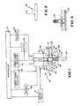
- FIG. 2shows a side plan view of a first alternatively preferred pin for use with the tool of FIG. 1;
- FIG. 3shows a portion of the tool of FIG. 1 with the lower shoulder member removed.
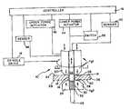
- FIG. 1schematically illustrates a preferred embodiment of a friction stir welding device 10 for friction stir welding application.
- the tool 10welds workpiece sections 12 , 14 at joint 16 .
- the tool 10is connected to a spindle drive 18 , or other driver, which rotates upper shoulder member 20 along with pin 22 and lower shoulder member 24 when attached as shown in FIG. 1 .
- the pin and lower shoulder member(when attached) may be rotationally driven either dependently (at the same rotational velocity) or independently (thereby allowing different rotational velocities) relative to the upper shoulder member.
- FIG. 1shows the tool 10 configured for self-reacting friction stir welding (SR-FSW).
- the lower shoulder member 24is attached to the pin 22 .
- the pin 22is equipped with threads 30 which cooperate with internal threads 32 in the lower shoulder member 24 .
- cooperating threads 30are one way of retaining the pin 22 to the lower shoulder member 24 , other connectors and/or methods may also be utilized so that the lower shoulder member 24 may be detached and reattached at the will of the operator.
- the lower shoulder member 24is connected intermediate the upper shoulder 26 and the distal end 25 of the pin 22 .
- the lower shoulder member 24may be selectively removed from the tool 10 .
- the lower shoulder member 24is shown in an installed configuration and in use relative to the pin 22 and upper shoulder member 20 so that SR-SFW can be performed on the work pieces 12 , 14 .
- the lower shoulder member 24has been removed from the pin 22 and tool 10 such that the same pin 22 , or alternatively another pin as will be discussed below, can be utilized to perform conventional friction stir welding as is known in the art and as seen in FIG. 3 .
- Upper shoulder member 20is shown in FIG. 1 supported so that upper shoulder 26 abuts upper surfaces 34 , 36 of work piece sections 12 , 14 .
- Pin 22extends through the joint 16 and lower shoulder 28 of lower shoulder member 24 .
- Lower shoulder 28abuts lower surfaces 38 , 40 of work piece sections 12 , 14 .
- An upper forge actuator 42is illustrated coupled to the upper shoulder member 20 and a lower forge actuator 44 is illustrated coupled to the lower shoulder member 24 , when installed, through pin 22 .
- the spindle drive 18rotates and the upper and lower shoulder members; and the upper and lower forge actuators 42 , 44 supply forging forces F g1 , F g2 to upper and lower shoulder members 20 , 24 , respectively. Rotation of pin 22 and upper and lower shoulder members 20 , 24 generates friction heat to create a plasticized region for joining the work sections 12 , 14 together.
- Upper and lower forge actuators 42 , 44 and spindle drive 18are connected to controller 46 as schematically illustrated in FIG. 1 for operation.
- the controller 46directs upper and lower forge actuators 42 , 44 to maintain upper and lower shoulder members 20 , 24 and shoulders 26 , 28 in abutment with upper and lower surfaces 34 , 36 and 38 , 40 , respectively, of the work pieces 12 , 14 to compensate for variations in work piece thicknesses and to provide a predetermined load on opposed surfaces of the work pieces 12 , 14 .
- Sensors 48 and 50are preferably utilized to provide feedback to the controller 46 .
- the sensors 48 , 50may be utilized to sense real-time force and/or position of the shoulders 26 , 28 . By providing the sensors 48 , 50 , the position of, or forging force on, the upper and lower shoulders 26 , 28 may be manipulated in real time by the controller 46 .
- the upper shoulder membermay also be completely removed and replace in order to provide the optimum shoulder geometry for the applicable process.
- the upper shoulder membercan also be replaced with a tool holder that can be used to hold a conventional fixed-pin friction stir welding pin-tool. In the case of a using a conventional fixed-pin design the auto-adjustable pin must be removed or withdrawn into the spindle.
- the lower force forge actuator 44functions more similarly to an auto-adjustable pin tool mechanism as described in U.S. Pat. No. 5,893,507. Specifically, as the tool 10 traverses an increasing thickness of the work piece, increased pressure is experienced on the upper shoulder member 26 . The controller 46 senses this rise in pressure, and/or change in position of the work piece surface, and withdraws the upper shoulder member 20 to keep the pressure and or position relative to the work piece surface constant. At the same time the lower forge actuator 44 extends the pin 22 further from the shoulder to keep the pin tip 22 at the proper position relative to the work pieces 12 , 14 .
- the controller 46moves the upper shoulder member towards the work pieces 12 , 14 (because of decreasing work piece 12 , 14 thicknesses) to maintain a constant pressure sensed at the sensor 48 and/or constant position of the shoulder relative to the work piece surface.
- the lower force forge actuator 44moves upward to withdraw the pin tip 22 to the appropriate position relative to the work pieces 12 , 14 .
- a switch 52is preferably utilized to inform the controller 46 of whether the lower shoulder member 24 is attached or not.
- the controller 46may withdraw the pin 22 with a lower forge actuator 44 , and upon not sensing forge F g2 , will thereby activate switch 52 to allow the lower forge actuator 94 to provide auto adjusting pin tool (APT) capability in the conventional friction stir welding mode shown in FIG. 3 .
- the switch 52may be utilized to inform the controller 46 whether the pin 21 of FIG. 2 is utilized or the pin 22 of FIG. 3, or another appropriate pin or fixed-pin tool, is utilized without the lower shoulder member 24 connected thereto.
Landscapes
- Engineering & Computer Science (AREA)
- Mechanical Engineering (AREA)
- Pressure Welding/Diffusion-Bonding (AREA)
Abstract
Description
This invention was made by an employee of the United States Government and may be manufactured and used by or for the Government for governmental purposes without the payment of any royalties thereon or thereof.
1. Field of the Invention
The present invention is directed to a friction stir welding device and, more particularly, to a machine tool capable of performing conventional friction stir welding while manipulating pin length in real time as well as capable of performing self-reacting friction stir welding while making real time adjustments to the distance between the upper and lower shoulders.
2. Description of Related Art
The general concept of friction stir welding is described in U.S. Pat. No. 5,460,317. Conventional friction stir welding is a process of welding component pails together using the frictional heat generated by a non-consumable tool to join work piece sections. The tool includes a pin that is inserted into the joint and a shoulder that is urged against an upper surface of the work piece. The pin and shoulder rotate to generate friction needed to create a plasticized region along the joint for the welding operation.
For conventional friction stir welding operation, a workpiece is generally supported by a rigid table or anvil typically formed with a steel plate. The anvil stabilizes the actuation force of the upper shoulder to maintain the integrity of the workpiece so that the workpiece does not bend or deform under load. In order to maximize the strength of the joint between workpiece sections, the pin should extend the entire thickness of the workpiece. U.S. Pat. No. 6,199,745 attempts to address this issue by providing a unique probe pin. This pin allows for self-reacting friction stir welding since it has a rotating bottom shoulder that cooperates with the upper shoulder. However, it makes no provision for performing conventional friction stir welding.
Other improvements have taken place in this art. U.S. Pat. No. 5,893,507 describes an auto-adjustment pin tool for friction stir welding which allows the pin to be incrementally withdrawn from the workpiece thereby eliminating craters or key holes in the weld after completion of the weld. While this design may be effective for conventional friction stir welding, it makes no provision for self-reacting friction stir welding.
U.S. Pat. No. 5,697,544 shows an adjustable pin for a friction stir welding tool which allows the shoulder to move relative to the pin tool. This design makes no provision for self-reacting friction stir welding.
Accordingly, there exists a need for a tool and method for performing both conventional and self-reacting friction stir welding which will provide for the adjustment of the pin length in real time during conventional welding as well as for the adjustment of the distance between the upper and lower shoulders in real time during self-reacting friction stir welding.
An object of the present invention is to provide a tool which can perform both conventional friction stir welding (FSW) as well as self-reacting friction stir welding (SR-FSW).
Another object of the present invention is to provide a method for providing FSW and SR-FSW utilizing auto-adjustable pin tool (APT) technology as well as an ability to adjust the distance between opposing shoulders when performing SR-FSW.
Another object of the present invention is to provide a dual capability machine tool not known in the art to provide both FSW and SR-FSW capability.
Another object of the present invention is to incorporate auto-adjustable pin tool (APT) technology into a machine tool for performing either FSW or SR-FSW processes.
Another object of the present invention is to provide a tool having the ability to provide a replaceable upper shoulder and pin and/or to add and subsequently remove a lower side shoulder from the pin so that a single tool can be utilized to perform conventional as well as self-reacting FSW.
By providing this capability in a FSW device, it is believed that a significant reduction in costs can be experienced by a facility contemplating the purchase of conventional FSW equipment as well as SR-FSW equipment. The tool is preferably equipped with a replaceable upper shoulder and pin and/or a pin configured to receive a removable lower shoulder. Accordingly, a single tool may be utilized for both FSW and SR-FSW operations. A closed-loop control system allows the position and/or load on each shoulder (in SR-FSW), or on the upper shoulder and pin (in conventional FSW), to be controlled independently or in unison.
The particular features and advantages of the invention as well as other objects will become apparent from the following description taken in connection with the accompanying drawings in which:
FIG. 1 shows a schematic cut away view of a friction stir welding device constructed in accordance with the presently preferred embodiment of the present invention;
FIG. 2 shows a side plan view of a first alternatively preferred pin for use with the tool of FIG. 1; and
FIG. 3 shows a portion of the tool of FIG. 1 with the lower shoulder member removed.
FIG. 1 schematically illustrates a preferred embodiment of a frictionstir welding device 10 for friction stir welding application. Thetool 10welds workpiece sections joint 16. Thetool 10 is connected to aspindle drive 18, or other driver, which rotatesupper shoulder member 20 along withpin 22 andlower shoulder member 24 when attached as shown in FIG.1. The pin and lower shoulder member (when attached) may be rotationally driven either dependently (at the same rotational velocity) or independently (thereby allowing different rotational velocities) relative to the upper shoulder member.
FIG. 1 shows thetool 10 configured for self-reacting friction stir welding (SR-FSW). In this embodiment, thelower shoulder member 24 is attached to thepin 22. In the illustration, thepin 22 is equipped withthreads 30 which cooperate withinternal threads 32 in thelower shoulder member 24. By coordinating the direction of thethreads 30 andinternal threads 32 of thelower shoulder member 24 along with the direction of rotation of thespindle drive 18, thelower shoulder member 24 can be retained on thepin 22. Although cooperatingthreads 30 are one way of retaining thepin 22 to thelower shoulder member 24, other connectors and/or methods may also be utilized so that thelower shoulder member 24 may be detached and reattached at the will of the operator. Thelower shoulder member 24 is connected intermediate theupper shoulder 26 and thedistal end 25 of thepin 22.
As can be seen from FIG. 3, thelower shoulder member 24 may be selectively removed from thetool 10. In FIG. 1, thelower shoulder member 24 is shown in an installed configuration and in use relative to thepin 22 andupper shoulder member 20 so that SR-SFW can be performed on thework pieces lower shoulder member 24 has been removed from thepin 22 andtool 10 such that thesame pin 22, or alternatively another pin as will be discussed below, can be utilized to perform conventional friction stir welding as is known in the art and as seen in FIG.3.
Upper andlower forge actuators spindle drive 18 are connected to controller46 as schematically illustrated in FIG. 1 for operation. The controller46 directs upper andlower forge actuators lower shoulder members shoulders lower surfaces work pieces work pieces Sensors sensors shoulders sensors lower shoulders
Although this configuration works satisfactory for SR-FSW, it may be that the user desires atool 10 which has the capability of performing SR-FSW as well as conventional FSW. In conventional FSW, there is nolower shoulder 28 orlower shoulder member 24 utilized. In fact, ananvil 52, illustrated in FIG. 3, or other appropriate lower surface is normally provided. Obviously, there is no way that alower force actuator 44 could be utilized to apply forging force Fg2independently of forging force Fg1as shown in FIG.1. In order to switch from the SR-FSW process or mode shown in FIG. 1 to the conventional FSW process or mode shown in FIG. 3, thelower shoulder member 24 is removed from thepin 22. Alternatively, pin21 as shown in FIG. 2 may be utilized for the SR-FSW mode and then replaced withpin 22 as shown in FIG. 3 or another conventional friction stir weld pin known in the art. The upper shoulder member may also be completely removed and replace in order to provide the optimum shoulder geometry for the applicable process. The upper shoulder member can also be replaced with a tool holder that can be used to hold a conventional fixed-pin friction stir welding pin-tool. In the case of a using a conventional fixed-pin design the auto-adjustable pin must be removed or withdrawn into the spindle.
When operating in the conventional friction stir welding mode as shown in FIG. 3, the lowerforce forge actuator 44 functions more similarly to an auto-adjustable pin tool mechanism as described in U.S. Pat. No. 5,893,507. Specifically, as thetool 10 traverses an increasing thickness of the work piece, increased pressure is experienced on theupper shoulder member 26. The controller46 senses this rise in pressure, and/or change in position of the work piece surface, and withdraws theupper shoulder member 20 to keep the pressure and or position relative to the work piece surface constant. At the same time thelower forge actuator 44 extends thepin 22 further from the shoulder to keep thepin tip 22 at the proper position relative to thework pieces sensor 48 senses a reduction material thickness and/or forging pressure, the controller46 moves the upper shoulder member towards thework pieces 12,14 (because of decreasingwork piece sensor 48 and/or constant position of the shoulder relative to the work piece surface. At the same time the lowerforce forge actuator 44 moves upward to withdraw thepin tip 22 to the appropriate position relative to thework pieces
In order to change the controller46 from SR-FSW to conventional FSW mode, aswitch 52 is preferably utilized to inform the controller46 of whether thelower shoulder member 24 is attached or not. Alternatively, the controller46 may withdraw thepin 22 with alower forge actuator 44, and upon not sensing forge Fg2, will thereby activateswitch 52 to allow the lower forge actuator94 to provide auto adjusting pin tool (APT) capability in the conventional friction stir welding mode shown in FIG.3. Alternatively, theswitch 52 may be utilized to inform the controller46 whether the pin21 of FIG. 2 is utilized or thepin 22 of FIG. 3, or another appropriate pin or fixed-pin tool, is utilized without thelower shoulder member 24 connected thereto.
Numerous alterations of the structure herein disclosed will suggest themselves to those skilled in the art. However, it is to be understood that the present disclosure relates to the preferred embodiment of the invention, which is for purposes of illustration only, and not to be construed as a limitation of the invention. All such modifications, which do not depart from the spirit of the invention, are intended to be included within the scope of the appended claims.
Claims (19)
1. A friction stir welding device comprising:
an upper shoulder having a bore therethrough;
a pin extending perpendicularly along a pin axis through the shoulder, said pin having a distal end, said upper shoulder and said pin rotatably driven independently (the upper shoulder and the pin are not mechanically tied and may rotate at different rates) in a welding operation; and
a lower shoulder removably connected to the pin intermediate the upper shoulder and the distal end of the pin, said lower shoulder having a larger perimeter than the pin;
wherein the lower shoulder member further comprises a feature extending into the lower shoulder member which receives a portion of the pin with said feature mechanically locking the lower shoulder member to the pin.
2. The friction stir welding tool ofclaim 1 wherein the upper shoulder and pin are rotatably drivein in an independent rotation, wherein independent rotation is provided when the shoulder and pin are not mechanically tied together.
3. The friction stir welding tool ofclaim 1 further comprising a lower shoulder member and the lower shoulder is a portion of the lower shoulder member.
4. The friction stir welding tool ofclaim 1 wherein the lower shoulder further comprises a bore that is threaded and threadably receives the pin intermediate the distal end of the pin and the upper shoulder.
5. The friction stir welding tool ofclaim 1 further comprising an upper shoulder member and the upper shoulder is a portion of the upper shoulder member.
6. The friction stir welding tool ofclaim 2 wherein the pin and upper shoulder arm rotatably driven by a spindle drive.
7. A friction stir welding device comprising:
an upper shoulder having a bore therethrough;
a pin extending perpendicularly along a pin axis through the shoulder, said pin having a distal end, said upper shoulder and said pin rotatably driven either dependently (shoulder and pin are mechanically tied and rotate together) or independently (shoulder and pin are not mechanically tied and may rotate at different rates) in a welding operation;
a lower shoulder removably connected to the pin intermediate the upper shoulder and the distal end of the pin, said lower shoulder having a larger perimeter than the pin; and
a controller having a conventional stir welding mode and a self-reacting friction stir welding mode, and when in said conventional friction stir welding mode, one of a force applied by the upper shoulder and a discrete position of one of the upper shoulder and pin are controlled by the controller, and when in said self-reacting friction stir welding mode, the force applied by the upper and lower shoulders and a discrete position of the upper and lower shoulders are controlled by the controller.
8. The friction stir welding tool ofclaim 7 further comprising an upper forge assembly operably coupled to the controller and the upper shoulder, and a lower forge assembly operably coupled to the controller and the pin, said upper forge assembly configured to move the upper shoulder up and down relative to the pin axis, and said lower forge assembly configured to move the pin up and down along the pin axis.
9. The friction stir welding tool ofclaim 7 further comprising a switch having a first and second position, and when said switch is in the first position, said controller is in the conventional stir welding mode, and when in the second position, said controller is in the self-reacting stir welding mode.
10. A friction stir welding tool configured to perform at least one of conventional and self-reacting friction stir welding on a workpiece, said tool comprising:
an upper shoulder member, said upper shoulder member rotationally driven during a welding operation, and said upper shoulder member having an upper shoulder, said upper shoulder adapted to be movable toward and away from the workpiece;
an upper forge assembly operably coupled to the upper shoulder for moving the upper shoulder towards and away from the workpiece;
a pin extending through the upper shoulder member to contact the workpiece;
a lower forge assembly operably coupled to the pin for moving the pin toward and away from the workpiece; and
a controller in communication with the upper and lower forge assemblies, said controller having a conventional friction stir welding mode and a self-reacting friction stir welding mode;
wherein when in said conventional friction stir welding mode, said lower forge assembly controls one of a discrete position of the pin and a force of insertion of the pin into the workpiece, and when in said self-reacting friction stir welding mode, said lower forge assembly controls one of a lower forging force applied through the pin to a lower surface of a workpiece and a discrete position of the lower shoulder.
11. The friction stir welding tool ofclaim 10 further comprising a switch, said switch changing the operation of the controller from conventional stir welding mode to self-reacting friction stir welding mode.
12. The friction stir welding tool ofclaim 10 wherein the switch is user activated.
13. The friction stir welding tool ofclaim 11 further comprising a lower shoulder movable with the pin below the workpiece and wherein the switch is activated based on the lower forging force reported to the controller.
14. The friction stir welding tool ofclaim 11 wherein the pin has a connector, and a lower shoulder member is attached to the connector in an attached configuration with said lower shoulder member having a lower shoulder contacting the lower surface of the workpiece, and said lower shoulder member is not attached to the connector in a disconnected configuration.
15. A friction stir welding tool configured to perform at least one of conventional and self-reacting friction stir welding on a workpiece, said tool comprising:
an upper shoulder member rotationally driven during a welding operation about a rotation axis, and said upper shoulder member having an upper shoulder, said upper shoulder adapted to be linearly movable along the rotation axis;
an upper forge assembly operably coupled to the upper shoulder for moving the upper shoulder linearly along the rotation axis;
a pin extending through the upper shoulder member along the rotation axis and having a distal end;
a lower forge assembly operably coupled to the pin for moving the pin along the rotation axis independently of the linear movement of the upper shoulder by the upper forge assembly; and
a controller in communication with the upper and lower forge assemblies, said controller having a conventional friction stir welding mode and a self-reacting friction stir welding mode;
wherein when in said conventional friction stir welding mode, said lower forge assembly controls one of a discrete position of the pin and a force of the pin along the rotation axis, and when in said self-reacting friction stir welding mode, said lower forge assembly controls one of a lower forging force applied through the pin to a lower surface of a workpiece and a discrete position of the lower shoulder.
16. The friction stir welding tool ofclaim 15 further comprising a lower shoulder member, and wherein the pin further comprises a connector intermediate the upper shoulder member and the distal end of the pin; said connector cooperating with the lower shoulder member in a connected configuration to secure the lower shoulder member to the pin, and said controller placed in the self-reacting friction stir welding mode.
17. The friction stir welding tool ofclaim 16 wherein the lower shoulder member is not attached to the pin in a disconnected configuration, and said controller placed in the conventional friction stir welding mode.
18. The friction stir welding tool ofclaim 15 further comprising a switch changing the controller from the conventional to the self-reacting friction stir welding mode.
19. The friction stir welding tool ofclaim 15 wherein the pin is initially provided with a lower shoulder.
Priority Applications (1)
| Application Number | Priority Date | Filing Date | Title |
|---|---|---|---|
| US10/431,655US6758382B1 (en) | 2003-05-02 | 2003-05-02 | Auto-adjustable tool for self-reacting and conventional friction stir welding |
Applications Claiming Priority (1)
| Application Number | Priority Date | Filing Date | Title |
|---|---|---|---|
| US10/431,655US6758382B1 (en) | 2003-05-02 | 2003-05-02 | Auto-adjustable tool for self-reacting and conventional friction stir welding |
Publications (1)
| Publication Number | Publication Date |
|---|---|
| US6758382B1true US6758382B1 (en) | 2004-07-06 |
Family
ID=32595078
Family Applications (1)
| Application Number | Title | Priority Date | Filing Date |
|---|---|---|---|
| US10/431,655Expired - Fee RelatedUS6758382B1 (en) | 2003-05-02 | 2003-05-02 | Auto-adjustable tool for self-reacting and conventional friction stir welding |
Country Status (1)
| Country | Link |
|---|---|
| US (1) | US6758382B1 (en) |
Cited By (53)
| Publication number | Priority date | Publication date | Assignee | Title |
|---|---|---|---|---|
| US20050156010A1 (en)* | 2003-05-05 | 2005-07-21 | Flak Richard A. | Applications of friction stir welding using a superabrasive tool |
| US20060043151A1 (en)* | 2004-08-30 | 2006-03-02 | Israel Stol | Advanced friction stir welding tools |
| US20060065694A1 (en)* | 2004-09-28 | 2006-03-30 | Israel Stol | Multi-shouldered fixed bobbin tools for simultaneous friction stir welding of multiple parallel walls between parts |
| US20060086775A1 (en)* | 2004-10-22 | 2006-04-27 | Edison Welding Institute | Method of friction stir welding and retractable shoulderless variable penetration friction stir welding tool for same |
| US20060163328A1 (en)* | 2003-08-29 | 2006-07-27 | General Electric Company | Apparatus and method for friction stir welding using a consumable pin tool |
| US20060289604A1 (en)* | 2005-06-27 | 2006-12-28 | Gkss-Forschungszentrum Geesthacht Gmbh | Friction stir welding appparatus |
| US20060289603A1 (en)* | 2005-06-27 | 2006-12-28 | Gkss-Forschungszentrum Geesthacht Gmbh | Apparatus and process for friction stir welding |
| US20070057015A1 (en)* | 2005-09-09 | 2007-03-15 | Kevin Colligan | Tapered friction stir welding and processing tool |
| US20070257058A1 (en)* | 2006-05-02 | 2007-11-08 | Heiner Ophardt | Wall plate system with releasable lock |
| US20080011810A1 (en)* | 2006-07-17 | 2008-01-17 | Burford Dwight A | Friction stir welding tool |
| US7383975B2 (en) | 2004-08-30 | 2008-06-10 | Alcoa Inc. | Fracture resistant friction stir welding tools |
| US20080217377A1 (en)* | 2007-03-06 | 2008-09-11 | Alcoa Inc. | Fracture Resistant Friction Stir Welding Tool |
| US20080251571A1 (en)* | 2007-04-13 | 2008-10-16 | Burford Dwight A | Friction stir welding tool having a counterflow pin configuration |
| US20080257936A1 (en)* | 2004-10-22 | 2008-10-23 | Trapp Timothy J | Multi-section faced shoulderless retractable variable penetration friction stir welding tool |
| US20090065553A1 (en)* | 2007-09-07 | 2009-03-12 | Burg James T | Friction stir welding apparatus |
| FR2921575A1 (en)* | 2007-09-27 | 2009-04-03 | Eads Europ Aeronautic Defence | DOUBLE - SHAPING WELDING DEVICE FOR WELDING FRICTION - MIXED PIECES AND METHOD FOR WELDING. |
| US20090230173A1 (en)* | 2008-03-14 | 2009-09-17 | Israel Stol | Advanced multi-shouldered fixed bobbin tools for simultaneous friction stir welding of multiple parallel walls between parts |
| US20090255980A1 (en)* | 2008-04-15 | 2009-10-15 | Lockheed Martin Corporation | Control systems for friction stir welding of titanium alloys and other high temperature materials |
| US20100044415A1 (en)* | 2006-09-12 | 2010-02-25 | Tosoh Smd, Inc. | Sputtering target assembly and method of making same |
| US7686202B1 (en) | 2006-09-29 | 2010-03-30 | The United States Of America As Represented By The Administrator Of The National Aeronautics And Space Administration | Gimbaled-shoulder friction stir welding tool |
| US20100163604A1 (en)* | 2008-12-29 | 2010-07-01 | Noe Andreas | Method of and apparatus for splicing metal strips |
| US20100213242A1 (en)* | 2007-03-30 | 2010-08-26 | Kawasaki Jukogyo Kabushiki Kaisha | Sticking pad, friction stir welding machine and friction stir welding system |
| CN101947691A (en)* | 2010-09-29 | 2011-01-19 | 哈尔滨工业大学 | Self-supporting friction stir welding method with unequal diameters of upper and lower shaft shoulders and stirring head thereof |
| CN101979209A (en)* | 2010-11-29 | 2011-02-23 | 哈尔滨工业大学 | Self-sustaining friction stir welding method with reverse rotation of upper and lower shoulders |
| US20110180587A1 (en)* | 2008-06-26 | 2011-07-28 | Edison Welding Institute, Inc. | Friction stir welding tool |
| US8079276B2 (en) | 2008-04-15 | 2011-12-20 | Spirit Aerosystems, Inc. | Dynamic calibration assembly for a friction stir welding machine |
| CN102601517A (en)* | 2012-04-06 | 2012-07-25 | 江苏科技大学 | Same-direction different-speed double-shoulder stir friction welding device and application method |
| EP2505296A1 (en)* | 2011-04-01 | 2012-10-03 | Helmholtz-Zentrum Geesthacht Zentrum für Material- und Küstenforschung GmbH | Friction stir welding apparatus |
| US20120279442A1 (en)* | 2005-09-26 | 2012-11-08 | Kevin Creehan | Self-reacting friction stir welding tool with the ability to add filler material |
| US20120279441A1 (en)* | 2005-09-26 | 2012-11-08 | Kevin Creehan | System for continuous feeding of filler material for friction stir welding, processing and fabrication |
| US20120298724A1 (en)* | 2011-05-27 | 2012-11-29 | Yoshinori Kato | Friction stir welding tool and friction stir welding apparatus |
| EP2564969A2 (en) | 2011-09-01 | 2013-03-06 | Airbus Operations GmbH | Friction stir welding method for connecting two panel-shaped workpieces and device for same |
| WO2012171523A3 (en)* | 2011-06-15 | 2013-04-04 | Eads Deutschland Gmbh | Welding tool comprising a rotating probe, welding method and workpiece |
| CN103052463A (en)* | 2010-09-03 | 2013-04-17 | 三菱日立制铁机械株式会社 | Double-side friction stir welding method for metal plates having gap between abutting portions |
| US8632850B2 (en) | 2005-09-26 | 2014-01-21 | Schultz-Creehan Holdings, Inc. | Friction fabrication tools |
| US8636194B2 (en) | 2005-09-26 | 2014-01-28 | Schultz-Creehan Holdings, Inc. | Friction stir fabrication |
| US20140069986A1 (en)* | 2011-03-18 | 2014-03-13 | Kawasaki Jukogyo Kabushiki Kaisha | Friction stir spot welding device and friction stir spot welding method |
| US20140069985A1 (en)* | 2011-03-18 | 2014-03-13 | Kawasaki Jukogyo Kabushiki Kaisha | Friction stir spot welding device and friction stir spot welding method |
| US20140217151A1 (en)* | 2011-08-21 | 2014-08-07 | Saga Tekkohsho Co., Ltd. | Friction stir welding tool |
| US20140231490A1 (en)* | 2011-10-14 | 2014-08-21 | Nippon Sharyo, Ltd. | Friction stir welding apparatus |
| US20140299051A1 (en)* | 2011-11-08 | 2014-10-09 | Hochschule Für Angewandte Wissenschaften - Fachhochschule Kempten | Friction application device |
| US9266191B2 (en) | 2013-12-18 | 2016-02-23 | Aeroprobe Corporation | Fabrication of monolithic stiffening ribs on metallic sheets |
| US20160074957A1 (en)* | 2013-04-16 | 2016-03-17 | Kawasaki Jukogyo Kabushiki Kaisha | Friction stir welding apparatus and friction stir welding method |
| US9511446B2 (en) | 2014-12-17 | 2016-12-06 | Aeroprobe Corporation | In-situ interlocking of metals using additive friction stir processing |
| US9511445B2 (en) | 2014-12-17 | 2016-12-06 | Aeroprobe Corporation | Solid state joining using additive friction stir processing |
| US20170157699A1 (en)* | 2014-04-16 | 2017-06-08 | Honda Motor Co., Ltd. | Friction stir welding apparatus |
| US20170297142A1 (en)* | 2015-01-09 | 2017-10-19 | Ihi Corporation | Friction stir welding method |
| US20180050420A1 (en)* | 2016-08-17 | 2018-02-22 | The Boeing Company | Apparatuses and methods for fabricating metal matrix composite structures |
| US10105791B2 (en) | 2015-01-27 | 2018-10-23 | The Boeing Company | Pin tool assemblies for friction stir welding and apparatus and methods including the same |
| US20200047279A1 (en)* | 2018-08-10 | 2020-02-13 | Spirit Aerosystems, Inc. | Friction stir welding machines and methods |
| CN112548311A (en)* | 2020-11-30 | 2021-03-26 | 上海航天设备制造总厂有限公司 | Tool for disassembling and stirring upper shaft shoulder and lower shaft shoulder after double-shaft-shoulder friction stir welding and using method |
| US11311959B2 (en) | 2017-10-31 | 2022-04-26 | MELD Manufacturing Corporation | Solid-state additive manufacturing system and material compositions and structures |
| CN115722788A (en)* | 2022-11-16 | 2023-03-03 | 航天工程装备(苏州)有限公司 | Double-shaft-shoulder friction stir welding device and system and automatic adjusting method |
Citations (17)
| Publication number | Priority date | Publication date | Assignee | Title |
|---|---|---|---|---|
| DE136143C (en)* | ||||
| US5460317A (en) | 1991-12-06 | 1995-10-24 | The Welding Institute | Friction welding |
| US5794835A (en) | 1996-05-31 | 1998-08-18 | The Boeing Company | Friction stir welding |
| WO1999052669A1 (en) | 1998-04-14 | 1999-10-21 | The Welding Institute | High performance tools for friction stir welding (fsw) |
| US6050474A (en) | 1997-07-23 | 2000-04-18 | Hitachi, Ltd. | Friction stir welding method, frame members used therein, and product formed thereby |
| US6199745B1 (en) | 1998-07-09 | 2001-03-13 | Mts Systems Corporation | Welding head |
| US6237835B1 (en) | 2000-02-29 | 2001-05-29 | The Boeing Company | Method and apparatus for backing up a friction stir weld joint |
| JP2001269780A (en)* | 2000-03-27 | 2001-10-02 | Ishikawajima Harima Heavy Ind Co Ltd | Low temperature liquefied gas container |
| JP2001287053A (en) | 2000-04-10 | 2001-10-16 | Hitachi Ltd | Friction stir welding method and welding device |
| JP2002018580A (en) | 2000-06-30 | 2002-01-22 | Hitachi Ltd | Friction stir welding method and welding device |
| JP2002045981A (en) | 2000-08-04 | 2002-02-12 | Hitachi Ltd | Friction stir welding method and joining structure |
| EP1188508A2 (en)* | 2000-09-13 | 2002-03-20 | Hitachi, Ltd. | Friction stir welding |
| US6367681B1 (en) | 2000-04-04 | 2002-04-09 | The Boeing Company | Friction stir welding apparatus and method |
| JP2003071574A (en)* | 2001-08-31 | 2003-03-11 | Nikkei Kako:Kk | Friction stir welding method and device |
| JP2003181654A (en)* | 2001-12-13 | 2003-07-02 | Mitsubishi Heavy Ind Ltd | Friction stir welding device |
| US20030201307A1 (en)* | 2002-04-29 | 2003-10-30 | The Boeing Company | Method and apparatus for friction stir welding |
| US20030209588A1 (en)* | 2002-05-07 | 2003-11-13 | Kevin Colligan | Tapered friction stir welding tool |
- 2003
- 2003-05-02USUS10/431,655patent/US6758382B1/ennot_activeExpired - Fee Related
Patent Citations (20)
| Publication number | Priority date | Publication date | Assignee | Title |
|---|---|---|---|---|
| DE136143C (en)* | ||||
| US5460317A (en) | 1991-12-06 | 1995-10-24 | The Welding Institute | Friction welding |
| US5460317B1 (en) | 1991-12-06 | 1997-12-09 | Welding Inst | Friction welding |
| US5794835A (en) | 1996-05-31 | 1998-08-18 | The Boeing Company | Friction stir welding |
| US6050474A (en) | 1997-07-23 | 2000-04-18 | Hitachi, Ltd. | Friction stir welding method, frame members used therein, and product formed thereby |
| WO1999052669A1 (en) | 1998-04-14 | 1999-10-21 | The Welding Institute | High performance tools for friction stir welding (fsw) |
| US6199745B1 (en) | 1998-07-09 | 2001-03-13 | Mts Systems Corporation | Welding head |
| US6237835B1 (en) | 2000-02-29 | 2001-05-29 | The Boeing Company | Method and apparatus for backing up a friction stir weld joint |
| JP2001269780A (en)* | 2000-03-27 | 2001-10-02 | Ishikawajima Harima Heavy Ind Co Ltd | Low temperature liquefied gas container |
| US6367681B1 (en) | 2000-04-04 | 2002-04-09 | The Boeing Company | Friction stir welding apparatus and method |
| JP2001287053A (en) | 2000-04-10 | 2001-10-16 | Hitachi Ltd | Friction stir welding method and welding device |
| JP2002018580A (en) | 2000-06-30 | 2002-01-22 | Hitachi Ltd | Friction stir welding method and welding device |
| JP2002045981A (en) | 2000-08-04 | 2002-02-12 | Hitachi Ltd | Friction stir welding method and joining structure |
| EP1188508A2 (en)* | 2000-09-13 | 2002-03-20 | Hitachi, Ltd. | Friction stir welding |
| JP2002086281A (en)* | 2000-09-13 | 2002-03-26 | Hitachi Ltd | Friction stir welding method |
| US6557746B2 (en)* | 2000-09-13 | 2003-05-06 | Hitachi, Ltd. | Friction stir bonding method |
| JP2003071574A (en)* | 2001-08-31 | 2003-03-11 | Nikkei Kako:Kk | Friction stir welding method and device |
| JP2003181654A (en)* | 2001-12-13 | 2003-07-02 | Mitsubishi Heavy Ind Ltd | Friction stir welding device |
| US20030201307A1 (en)* | 2002-04-29 | 2003-10-30 | The Boeing Company | Method and apparatus for friction stir welding |
| US20030209588A1 (en)* | 2002-05-07 | 2003-11-13 | Kevin Colligan | Tapered friction stir welding tool |
Cited By (104)
| Publication number | Priority date | Publication date | Assignee | Title |
|---|---|---|---|---|
| US20050156010A1 (en)* | 2003-05-05 | 2005-07-21 | Flak Richard A. | Applications of friction stir welding using a superabrasive tool |
| US7530486B2 (en)* | 2003-05-05 | 2009-05-12 | Sii Megadiamond, Inc. | Applications of friction stir welding using a superabrasive tool |
| US7784667B2 (en)* | 2003-08-29 | 2010-08-31 | General Electric Company | Apparatus and method for friction stir welding using a consumable pin tool |
| US20060163328A1 (en)* | 2003-08-29 | 2006-07-27 | General Electric Company | Apparatus and method for friction stir welding using a consumable pin tool |
| US20060043151A1 (en)* | 2004-08-30 | 2006-03-02 | Israel Stol | Advanced friction stir welding tools |
| US7401723B2 (en) | 2004-08-30 | 2008-07-22 | Alcoa Inc. | Advanced friction stir welding tools |
| US7383975B2 (en) | 2004-08-30 | 2008-06-10 | Alcoa Inc. | Fracture resistant friction stir welding tools |
| US20060065694A1 (en)* | 2004-09-28 | 2006-03-30 | Israel Stol | Multi-shouldered fixed bobbin tools for simultaneous friction stir welding of multiple parallel walls between parts |
| WO2006037051A3 (en)* | 2004-09-28 | 2006-10-05 | Alcoa Inc | Multi-shouldered fixed bobbin tools for simultaneous friction stir welding |
| US7198189B2 (en)* | 2004-09-28 | 2007-04-03 | Alcoa Inc. | Multi-shouldered fixed bobbin tools for simultaneous friction stir welding of multiple parallel walls between parts |
| US20080257936A1 (en)* | 2004-10-22 | 2008-10-23 | Trapp Timothy J | Multi-section faced shoulderless retractable variable penetration friction stir welding tool |
| US20070228102A1 (en)* | 2004-10-22 | 2007-10-04 | Trapp Timothy J | Retractable shoulderless variable penetration friction stir welding tool |
| US20060086775A1 (en)* | 2004-10-22 | 2006-04-27 | Edison Welding Institute | Method of friction stir welding and retractable shoulderless variable penetration friction stir welding tool for same |
| US7234626B2 (en)* | 2004-10-22 | 2007-06-26 | Edison Welding Institute, Inc. | Method of friction stir welding and retractable shoulderless variable penetration friction stir welding tool for same |
| US7404510B2 (en) | 2004-10-22 | 2008-07-29 | Edison Welding Institute, Inc. | Retractable shoulderless variable penetration friction stir welding tool |
| US20060289603A1 (en)* | 2005-06-27 | 2006-12-28 | Gkss-Forschungszentrum Geesthacht Gmbh | Apparatus and process for friction stir welding |
| US20060289604A1 (en)* | 2005-06-27 | 2006-12-28 | Gkss-Forschungszentrum Geesthacht Gmbh | Friction stir welding appparatus |
| US20070057015A1 (en)* | 2005-09-09 | 2007-03-15 | Kevin Colligan | Tapered friction stir welding and processing tool |
| US8397974B2 (en)* | 2005-09-26 | 2013-03-19 | Aeroprobe Corporation | Self-reacting friction stir welding tool with the ability to add filler material |
| US8893954B2 (en) | 2005-09-26 | 2014-11-25 | Aeroprobe Corporation | Friction stir fabrication |
| US20120279442A1 (en)* | 2005-09-26 | 2012-11-08 | Kevin Creehan | Self-reacting friction stir welding tool with the ability to add filler material |
| US8875976B2 (en)* | 2005-09-26 | 2014-11-04 | Aeroprobe Corporation | System for continuous feeding of filler material for friction stir welding, processing and fabrication |
| US9205578B2 (en) | 2005-09-26 | 2015-12-08 | Aeroprobe Corporation | Fabrication tools for exerting normal forces on feedstock |
| US20120279441A1 (en)* | 2005-09-26 | 2012-11-08 | Kevin Creehan | System for continuous feeding of filler material for friction stir welding, processing and fabrication |
| US8632850B2 (en) | 2005-09-26 | 2014-01-21 | Schultz-Creehan Holdings, Inc. | Friction fabrication tools |
| US9643279B2 (en) | 2005-09-26 | 2017-05-09 | Aeroprobe Corporation | Fabrication tools for exerting normal forces on feedstock |
| US8636194B2 (en) | 2005-09-26 | 2014-01-28 | Schultz-Creehan Holdings, Inc. | Friction stir fabrication |
| US20070257058A1 (en)* | 2006-05-02 | 2007-11-08 | Heiner Ophardt | Wall plate system with releasable lock |
| US20080011810A1 (en)* | 2006-07-17 | 2008-01-17 | Burford Dwight A | Friction stir welding tool |
| US8016179B2 (en) | 2006-07-17 | 2011-09-13 | Wichita State University | Friction stir welding tool having a scroll-free concentric region |
| US20100044415A1 (en)* | 2006-09-12 | 2010-02-25 | Tosoh Smd, Inc. | Sputtering target assembly and method of making same |
| US8235277B2 (en) | 2006-09-12 | 2012-08-07 | Tosoh Smd, Inc. | Sputtering target assembly and method of making same |
| US8020748B2 (en) | 2006-09-12 | 2011-09-20 | Toso SMD, Inc. | Sputtering target assembly and method of making same |
| US7686202B1 (en) | 2006-09-29 | 2010-03-30 | The United States Of America As Represented By The Administrator Of The National Aeronautics And Space Administration | Gimbaled-shoulder friction stir welding tool |
| US20100108742A1 (en)* | 2007-03-06 | 2010-05-06 | Israel Stol | Fracture resistant friction stir welding tools |
| US20080217377A1 (en)* | 2007-03-06 | 2008-09-11 | Alcoa Inc. | Fracture Resistant Friction Stir Welding Tool |
| US20100213242A1 (en)* | 2007-03-30 | 2010-08-26 | Kawasaki Jukogyo Kabushiki Kaisha | Sticking pad, friction stir welding machine and friction stir welding system |
| US7896216B2 (en)* | 2007-03-30 | 2011-03-01 | Kawasaki Jukogyo Kabushiki Kaisha | Sticking pad, friction stir welding machine and friction stir welding system |
| US20080251571A1 (en)* | 2007-04-13 | 2008-10-16 | Burford Dwight A | Friction stir welding tool having a counterflow pin configuration |
| US7942306B2 (en) | 2007-04-13 | 2011-05-17 | Wichita State University | Friction stir welding tool having a counterflow pin configuration |
| US7793816B2 (en) | 2007-09-07 | 2010-09-14 | Alcoa Inc. | Friction stir welding apparatus |
| US20090065553A1 (en)* | 2007-09-07 | 2009-03-12 | Burg James T | Friction stir welding apparatus |
| WO2009044077A3 (en)* | 2007-09-27 | 2009-05-28 | Eads Europ Aeronautic Defence | Double-shouldered welding device for the friction stir welding of parts, and welding method |
| US7931185B2 (en) | 2007-09-27 | 2011-04-26 | European Aeronautic Defence And Space Company Eads France | Double-shouldered welding device for the friction stir welding of parts, and welding method |
| JP2010540251A (en)* | 2007-09-27 | 2010-12-24 | ユーロピアン アエロノーティック ディフェンス アンド スペース カンパニー イーズ フランス | Joining apparatus and joining method with a double shoulder for joining members by friction stirring |
| FR2921575A1 (en)* | 2007-09-27 | 2009-04-03 | Eads Europ Aeronautic Defence | DOUBLE - SHAPING WELDING DEVICE FOR WELDING FRICTION - MIXED PIECES AND METHOD FOR WELDING. |
| US7854362B2 (en) | 2008-03-14 | 2010-12-21 | Alcoa Inc. | Advanced multi-shouldered fixed bobbin tools for simultaneous friction stir welding of multiple parallel walls between parts |
| US8413875B2 (en) | 2008-03-14 | 2013-04-09 | Alcoa Inc. | Advanced multi-shouldered fixed bobbin tools for simultaneous friction stir welding of multiple parallel walls between parts |
| US20100163603A1 (en)* | 2008-03-14 | 2010-07-01 | Alcoa Inc. | Advanced multi-shouldered fixed bobbin tools for simultaneous friction stir welding of multiple parallel walls between parts |
| US20090230173A1 (en)* | 2008-03-14 | 2009-09-17 | Israel Stol | Advanced multi-shouldered fixed bobbin tools for simultaneous friction stir welding of multiple parallel walls between parts |
| US8256657B2 (en) | 2008-03-14 | 2012-09-04 | Alcoa Inc. | Advanced multi-shouldered fixed bobbin tools for simultaneous friction stir welding of multiple parallel walls between parts |
| US20090255980A1 (en)* | 2008-04-15 | 2009-10-15 | Lockheed Martin Corporation | Control systems for friction stir welding of titanium alloys and other high temperature materials |
| WO2009146172A3 (en)* | 2008-04-15 | 2010-01-21 | Lockheed Martin Corporation | Control systems for friction stir welding of titanium alloys and other high temperature materials |
| EP2268446A4 (en)* | 2008-04-15 | 2012-05-02 | Lockheed Corp | Control systems for friction stir welding of titanium alloys and other high temperature materials |
| US8079276B2 (en) | 2008-04-15 | 2011-12-20 | Spirit Aerosystems, Inc. | Dynamic calibration assembly for a friction stir welding machine |
| US20110180587A1 (en)* | 2008-06-26 | 2011-07-28 | Edison Welding Institute, Inc. | Friction stir welding tool |
| US20100163604A1 (en)* | 2008-12-29 | 2010-07-01 | Noe Andreas | Method of and apparatus for splicing metal strips |
| US8109428B2 (en)* | 2008-12-29 | 2012-02-07 | BWG Bergwerk-und Walzwerk-Maschinenbau GmbH USA | Method of and apparatus for splicing metal strips |
| CN103052463A (en)* | 2010-09-03 | 2013-04-17 | 三菱日立制铁机械株式会社 | Double-side friction stir welding method for metal plates having gap between abutting portions |
| CN103052463B (en)* | 2010-09-03 | 2015-08-05 | 三菱日立制铁机械株式会社 | The both surface friction stirring joint method of the metallic plate in gap is there is in docking section |
| CN101947691B (en)* | 2010-09-29 | 2012-05-30 | 哈尔滨工业大学 | Self-supporting friction stir welding method with unequal diameters of upper and lower shaft shoulders and stirring head thereof |
| CN101947691A (en)* | 2010-09-29 | 2011-01-19 | 哈尔滨工业大学 | Self-supporting friction stir welding method with unequal diameters of upper and lower shaft shoulders and stirring head thereof |
| CN101979209A (en)* | 2010-11-29 | 2011-02-23 | 哈尔滨工业大学 | Self-sustaining friction stir welding method with reverse rotation of upper and lower shoulders |
| CN101979209B (en)* | 2010-11-29 | 2012-05-30 | 哈尔滨工业大学 | Self-sustaining friction stir welding method with reverse rotation of upper and lower shoulders |
| US9314870B2 (en) | 2011-03-18 | 2016-04-19 | Kawasaki Jukogyo Kabushiki Kaisha | Friction stir spot welding device and friction stir spot welding method |
| US20140069986A1 (en)* | 2011-03-18 | 2014-03-13 | Kawasaki Jukogyo Kabushiki Kaisha | Friction stir spot welding device and friction stir spot welding method |
| US20140069985A1 (en)* | 2011-03-18 | 2014-03-13 | Kawasaki Jukogyo Kabushiki Kaisha | Friction stir spot welding device and friction stir spot welding method |
| US9095926B2 (en)* | 2011-03-18 | 2015-08-04 | Kawasaki Jukogyo Kabushiki Kaisha | Friction stir spot welding device and friction stir spot welding method |
| US8950650B2 (en)* | 2011-03-18 | 2015-02-10 | Kawasaki Jukogyo Kabushiki Kaisha | Friction stir spot welding device and friction stir spot welding method |
| US8893951B2 (en) | 2011-04-01 | 2014-11-25 | Helmholtz-Zentrum Geesthacht Zentrum fur Material-und Kustenforschung GmbH | Apparatus for friction stir welding |
| EP2505296A1 (en)* | 2011-04-01 | 2012-10-03 | Helmholtz-Zentrum Geesthacht Zentrum für Material- und Küstenforschung GmbH | Friction stir welding apparatus |
| US20120298724A1 (en)* | 2011-05-27 | 2012-11-29 | Yoshinori Kato | Friction stir welding tool and friction stir welding apparatus |
| WO2012171523A3 (en)* | 2011-06-15 | 2013-04-04 | Eads Deutschland Gmbh | Welding tool comprising a rotating probe, welding method and workpiece |
| US9796133B2 (en) | 2011-06-15 | 2017-10-24 | Airbus Defence and Space GmbH | Welding tool comprising a rotating probe, welding method and workpiece |
| US8899468B2 (en)* | 2011-08-21 | 2014-12-02 | Honda Motor Co., Ltd. | Friction stir welding tool |
| US20140217151A1 (en)* | 2011-08-21 | 2014-08-07 | Saga Tekkohsho Co., Ltd. | Friction stir welding tool |
| EP2564969A2 (en) | 2011-09-01 | 2013-03-06 | Airbus Operations GmbH | Friction stir welding method for connecting two panel-shaped workpieces and device for same |
| DE102011112042A1 (en) | 2011-09-01 | 2013-03-07 | Airbus Operations Gmbh | Friction friction welding method for connecting plate-shaped workpieces and apparatus therefor |
| US9216472B2 (en)* | 2011-10-14 | 2015-12-22 | Nippon Sharyo, Ltd. | Friction stir welding apparatus comprising slide plates |
| US20140231490A1 (en)* | 2011-10-14 | 2014-08-21 | Nippon Sharyo, Ltd. | Friction stir welding apparatus |
| US10286480B2 (en) | 2011-11-08 | 2019-05-14 | Hochschule für angewandte Wissenschaften—Fachhochschule Kempten | Friction application device |
| US20140299051A1 (en)* | 2011-11-08 | 2014-10-09 | Hochschule Für Angewandte Wissenschaften - Fachhochschule Kempten | Friction application device |
| US9687934B2 (en)* | 2011-11-08 | 2017-06-27 | Hochschule für angewandte Wissenschaften—Fachhochschule Kempten | Friction application device |
| CN102601517A (en)* | 2012-04-06 | 2012-07-25 | 江苏科技大学 | Same-direction different-speed double-shoulder stir friction welding device and application method |
| US20160074957A1 (en)* | 2013-04-16 | 2016-03-17 | Kawasaki Jukogyo Kabushiki Kaisha | Friction stir welding apparatus and friction stir welding method |
| US9975200B2 (en)* | 2013-04-16 | 2018-05-22 | Kawasaki Jukogyo Kabushiki Kaisha | Friction stir welding apparatus with an L-shaped support |
| US9862054B2 (en) | 2013-12-18 | 2018-01-09 | Aeroprobe Corporation | Additive friction stir methods of repairing substrates |
| US10500674B2 (en) | 2013-12-18 | 2019-12-10 | MELD Manufacturing Corporation | Additive friction-stir fabrication system for forming substrates with ribs |
| US9266191B2 (en) | 2013-12-18 | 2016-02-23 | Aeroprobe Corporation | Fabrication of monolithic stiffening ribs on metallic sheets |
| US20170157699A1 (en)* | 2014-04-16 | 2017-06-08 | Honda Motor Co., Ltd. | Friction stir welding apparatus |
| US9975201B2 (en)* | 2014-04-16 | 2018-05-22 | Honda Motor Co., Ltd. | Friction stir welding apparatus |
| US10583631B2 (en) | 2014-12-17 | 2020-03-10 | MELD Manufacturing Corporation | In-situ interlocking of metals using additive friction stir processing |
| US10105790B2 (en) | 2014-12-17 | 2018-10-23 | Aeroprobe Corporation | Solid state joining using additive friction stir processing |
| US9511445B2 (en) | 2014-12-17 | 2016-12-06 | Aeroprobe Corporation | Solid state joining using additive friction stir processing |
| US9511446B2 (en) | 2014-12-17 | 2016-12-06 | Aeroprobe Corporation | In-situ interlocking of metals using additive friction stir processing |
| US20170297142A1 (en)* | 2015-01-09 | 2017-10-19 | Ihi Corporation | Friction stir welding method |
| US10105791B2 (en) | 2015-01-27 | 2018-10-23 | The Boeing Company | Pin tool assemblies for friction stir welding and apparatus and methods including the same |
| US10610960B2 (en) | 2015-01-27 | 2020-04-07 | The Boeing Company | Pin tool assemblies for friction stir welding and apparatus and methods including the same |
| US10279423B2 (en)* | 2016-08-17 | 2019-05-07 | The Boeing Company | Apparatuses and methods for fabricating metal matrix composite structures |
| US20180050420A1 (en)* | 2016-08-17 | 2018-02-22 | The Boeing Company | Apparatuses and methods for fabricating metal matrix composite structures |
| US11311959B2 (en) | 2017-10-31 | 2022-04-26 | MELD Manufacturing Corporation | Solid-state additive manufacturing system and material compositions and structures |
| US20200047279A1 (en)* | 2018-08-10 | 2020-02-13 | Spirit Aerosystems, Inc. | Friction stir welding machines and methods |
| CN112548311A (en)* | 2020-11-30 | 2021-03-26 | 上海航天设备制造总厂有限公司 | Tool for disassembling and stirring upper shaft shoulder and lower shaft shoulder after double-shaft-shoulder friction stir welding and using method |
| CN115722788A (en)* | 2022-11-16 | 2023-03-03 | 航天工程装备(苏州)有限公司 | Double-shaft-shoulder friction stir welding device and system and automatic adjusting method |
Similar Documents
| Publication | Publication Date | Title |
|---|---|---|
| US6758382B1 (en) | Auto-adjustable tool for self-reacting and conventional friction stir welding | |
| US6799708B2 (en) | Device for joining workpieces by friction stir welding | |
| JP7216551B2 (en) | Friction stir spot welding device and friction stir spot welding method | |
| US6497355B1 (en) | System for controlling the stirring pin of a friction stir welding apparatus | |
| US6726084B2 (en) | Friction stir heating/welding with pin tool having rough distal region | |
| US7703654B2 (en) | Counter-rotating spindle for friction stir welding | |
| EP1375050B1 (en) | Machining control method and robot | |
| US7748593B2 (en) | Friction stir welding apparatus and method of operating same | |
| US6604667B2 (en) | Device for joining, by friction stir welding, at least two workpieces | |
| US9764375B2 (en) | Friction bit joining of materials using a friction rivet | |
| US20100072261A1 (en) | Friction stir welding spindle downforce and other control techniques, systems and methods | |
| US20130228612A1 (en) | Friction bit joining of materials | |
| US11858060B2 (en) | Friction stir spot welding device and method for operating same | |
| JP7739521B2 (en) | Friction stir spot welding device and joint structure | |
| US11407060B2 (en) | Counter support, device and method for friction stir welding | |
| US20080217380A1 (en) | Method and apparatus to relieve residual stress or distortion in a heat processed article | |
| JP6339292B2 (en) | Spot welding method and apparatus | |
| US7060929B2 (en) | Sheet-to-tube resistance spot welding using servo gun | |
| JP2021062409A (en) | Friction stir spot joining apparatus and method of operating the same | |
| EP3094429B1 (en) | Friction bit joining of materials using a friction rivet |
Legal Events
| Date | Code | Title | Description |
|---|---|---|---|
| AS | Assignment | Owner name:NATIONAL AERONAUTICS AND SPACE ADMINISTRATION, DIS Free format text:ASSIGNMENT OF ASSIGNORS INTEREST;ASSIGNOR:CAMPBELL, ROBERT W.;REEL/FRAME:014057/0629 Effective date:20030502 | |
| AS | Assignment | Owner name:NATIONAL AERONAUTICS AND SPACE ADMINISTRATION, DIS Free format text:CORRECTIVE COVERSHEET TO CORRECT THE CONVEYING PARTY'S NAME THAT WAS PREVIOUSLY RECORDED ON REEL 014057, FRAME 0629.;ASSIGNOR:CARTER, ROBERT W.;REEL/FRAME:014086/0541 Effective date:20030502 | |
| FPAY | Fee payment | Year of fee payment:4 | |
| REMI | Maintenance fee reminder mailed | ||
| LAPS | Lapse for failure to pay maintenance fees | ||
| STCH | Information on status: patent discontinuation | Free format text:PATENT EXPIRED DUE TO NONPAYMENT OF MAINTENANCE FEES UNDER 37 CFR 1.362 | |
| FP | Lapsed due to failure to pay maintenance fee | Effective date:20120706 |