US6758370B2 - Product vending - Google Patents
Product vendingDownload PDFInfo
- Publication number
- US6758370B2 US6758370B2US09/485,118US48511800AUS6758370B2US 6758370 B2US6758370 B2US 6758370B2US 48511800 AUS48511800 AUS 48511800AUS 6758370 B2US6758370 B2US 6758370B2
- Authority
- US
- United States
- Prior art keywords
- product
- chute
- tongue
- products
- wall
- Prior art date
- Legal status (The legal status is an assumption and is not a legal conclusion. Google has not performed a legal analysis and makes no representation as to the accuracy of the status listed.)
- Expired - Lifetime
Links
Images


Classifications
- G—PHYSICS
- G07—CHECKING-DEVICES
- G07F—COIN-FREED OR LIKE APPARATUS
- G07F11/00—Coin-freed apparatus for dispensing, or the like, discrete articles
- G07F11/02—Coin-freed apparatus for dispensing, or the like, discrete articles from non-movable magazines
- G07F11/04—Coin-freed apparatus for dispensing, or the like, discrete articles from non-movable magazines in which magazines the articles are stored one vertically above the other
- G07F11/06—Coin-freed apparatus for dispensing, or the like, discrete articles from non-movable magazines in which magazines the articles are stored one vertically above the other supported individually on pivotally-mounted flaps or shelves
- G—PHYSICS
- G07—CHECKING-DEVICES
- G07F—COIN-FREED OR LIKE APPARATUS
- G07F11/00—Coin-freed apparatus for dispensing, or the like, discrete articles
- G07F11/02—Coin-freed apparatus for dispensing, or the like, discrete articles from non-movable magazines
- G07F11/04—Coin-freed apparatus for dispensing, or the like, discrete articles from non-movable magazines in which magazines the articles are stored one vertically above the other
- G07F11/16—Delivery means
- G07F11/163—Delivery means characterised by blocking access to the output bins
Definitions
- This inventionrelates to product vending and relates particularly but not exclusively to product vending apparatus and parts therefor suitable for vending high cost products such as consumables for computer printers.
- PCT/AU93/00416WO94/04446
- PCT/AU95/00154WO95/26004
- PCT/AU93/00416relates to a vending machine which facilitates recycling of complex articles, such as printer and toner cartridges.
- PCT/AU95/00154discloses an electronic catalogue device and system for enabling remote ordering of goods/services.
- the present inventionattempts to address one or more of the afore-mentioned problems.
- a dispensing mechanism for a vending machinefor permitting generally flat faced product to be vended one at a time, said mechanism comprising an upright storage chute in which identical shaped and sized product can be stacked one on top of the other so the flat face of said generally flat faced product lies generally transversely of vertical, said storage chute being defined by a first generally upright extending wall and a spaced and opposed second generally upright extended wall, the spacing being sufficient to allow the product to move in a generally vertical path in said chute by gravity from the top to the bottom of the chute,
- first tongue and a vertically lower spaced second tonguemounted to advance and retreat into said path through said second wall at the bottom of the stack, a lowermost product being supported in said chute by a support surface in said path opposite where said first tongue extends through said second wall and by said first tongue when said first tongue is advanced into said path through said second wall, the weight of all products being carried by said support surface and said first tongue,
- the vertical spacing of said first tongue and said second tonguebeing such that when the lowermost product is caught by the second tongue, the next highermost product in the stack will be positioned so that the first tongue can be advanced under that product so that that product and all products thereabove will be carried by said upper part of said inclined ramp and said first tongue, and so as said second tongue is retreated the product caught on said second tongue will fall by gravity onto said inclined ramp and pass through said discharge opening and be vended.
- first tongue and said second tonguebe mechanically interconnected for pivoting rocking movement for advancing and retreating and that the pivot axis be generally horizontal.
- solenoid meansbe connected to said first tongue and to said second tongue to effect advancing and retreating.
- said support surfacebe an upper part of said inclined ramp.
- said inclined ramphave a step at the upper part so that product supported by said first tongue and said upper part be supported at an upper part of said step, and so product supported by said upper part and said second tongue be supported at a lower part of said step.
- said storage chutebe one of a plurality of chute modules, and that each module be positioned one above the other to form a multiple module height chute so that a plurality of different products can be stacked in said multiple height chute and vended therefrom by advancing or retreating the appropriate first and second tongues.
- said multiple height chutebe a single chute with bays for each module and wherein the plurality of discharge openings be coverable by respective removable wall plates, that said plurality of first tongues and said second tongues be removable, and that said inclined ramps be removable, whereby a product vendor can choose to utilise the whole of the chute for one group of product in a range, or can utilise the chute for a plurality of different product groups in a range, thereby permitting multiple groups of products to be stacked in said chute and user selected for vending by operation of the corresponding first tongue and second tongue.
- said inclined rampbe of unitary construction but it may comprises two or more separate items.
- the first itemmay extend from or adjacent said first wall and the second item may extend from or adjacent a lower part of said upper part of said ramp.
- said rampbe swingable about its upper region so that when loading fresh product into said chute, said ramp can be swung by its lowermost part swinging upwardly to a generally horizontal position thereby closing the chute at the bottom of the chute and inhibiting against mis-oriented product falling through the chute and being discharged from said product discharge opening.
- a vending machinehaving a plurality of chute modules, each module having an upright extending chute in which identical shaped and size product can be stacked one on top of the other, said storage chute being defined by a first generally upright extending wall and a spaced and opposed second generally upright extending wall, the spacing being sufficient to allow the product to move in a generally vertical path in said chute by gravity from the top to the bottom of the chute, there being an inclined product discharge ramp extending across the bottom of the chute extending downwardly from adjacent the first wall to the second wall, and a product discharge opening in said second wall, there being a product dispensing mechanism at the bottom of the chute above said ramp, said product dispensing mechanism permitting the lowermost product in said chute to be vended by moving onto said ramp and passing through said opening whilst retaining all product higher than said lowermost product within said chute for subsequent vending,
- each modulebeing positioned one above the other whereby to provide a multiple module height chute so that a plurality of different products can be stacked in said multiple height chute and vended therefrom by advancing or retreating the appropriate first and second tongues.
- said multiple height chutebe a single chute with bays for each module and wherein the plurality of discharge openings be coverable by respective removable wall plates, said plurality of first tongues and said second tongues be removable, and that said inclined ramps be removable, whereby a product vendor can choose to utilise the whole of the chute for one group of product in a range, or can utilise a chute for a plurality of different product groups in a range, thereby permitting multiple groups of product to be stacked in said chute and user selected for vending by operation of the corresponding first tongue and second tongue.
- said rampbe swingable about its upper region so that when loading fresh product into said chute, said ramp can be swung from its lowermost part upwardly to a generally horizontal position thereby closing the chute at the bottom of the chute and inhibiting against mis-oriented product falling through the chute and being discharged from said product discharge opening.
- a vending machinefor vending product, said machine having a processing means, a user operable product selecting means, a dispensing mechanism for releasing stored product one at a time so said stored product can be vended, a product sensing means for sensing product dispensed from said dispensing mechanism and a product removal sensor,
- said product sensing means for sensing product dispensedcomprises a physical sensor in the path of the product as it is dispensed.
- said product sensing meansmay simply comprise providing a sensing signal in response to the user operable product selecting means being activated to dispense a product.
- said machinehas a multiple product vending feature, where multiple product can be ordered to be vended by a single purchase transaction at said machine, and wherein if said product removal sensor is not activated, the order will be terminated without dispensing of subsequent product in that order.
- said machinehas a credit card debit facility for charging for product dispensed, and wherein multiple product ordered to be vended by a single transaction is charged to said credit card, and wherein if said product removal sensor is not activated, the order will be terminated without dispensing of subsequent product in that order, and the credit card debit adjusted to reflect the cost of any product removed from said machine in that order.
- a dispensing mechanism for a vending machinefor permitting generally flat faced product to be vended one at a time, said mechanism comprising a storage bin with a generally horizontally extending but inclined floor on which said generally flat faced product can be supported on an edge face so that flat face extends generally upright and wherein product can be stacked side-by-side,
- the spacing between said tongue and said stopbeing such that a single product can be supported on the floor in said space and prevented from falling by gravity from said floor by said stop, and wherein said tongue is advanceable into said path to prevent movement of the next product in said path, so that when product is to be vended said stop can be moved away from the end of the floor thereby allowing the product to fall by gravity and to be vended, and to permit product held in said path by said tongue, and so that after vending said stop can be returned to the end of the floor and the tongue retreated thereby allowing the next product to move into said space between said tongue and said stop whereupon said tongue can then be advanced between the next product and the succeeding product making the machine ready for future vending.
- said movable stopis an end wall of said storage bin.
- said end wallis pivoted near the top of said storage bin so it can swing from a position where it is at the end of said floor to a position away from said floor.
- a latchfor holding said end wall at the position where it is at the end of said floor and wherein when said latch is released, the weight of product will cause said end wall to swing to said position away from said floor and to allow the product to fall by gravity off said floor, and wherein said latch can relatch said end wall as it return swings by gravity to the end of said floor.
- the end wallis mounted so it will return swing by gravity.
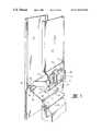
- FIG. 1is a front perspective view of the example of the preferred dispensing machine
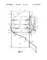
- FIG. 2is a side view of a dispensing machine for dispensing flat faced product such as inkjet printer cartridges;
- FIG. 3is a perspective view of the mechanism of FIG. 2;
- FIGS. 4, 5 , and 6are views similar to FIG. 2 showing different stages of operation
- FIG. 7is a perspective view similar to FIG. 3 showing a removable product discharge opening cover
- FIG. 8is a side view of a product retrieval sensor arrangement
- FIG. 9is a view similar to FIG. 8 showing the product retrieval sensor at a different stage of operation
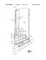
- FIGS. 10, 11 and 12are side views during different stages of operation of a further product discharge mechanism for dispensing media product on which printing is to be made by a computer printer;
- FIG. 13is a perspective view of the mechanism of FIGS. 10, 11 and 12 ;
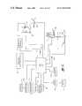
- FIG. 14is a schematic electrical block circuit diagram of the components
- FIG. 15is a software flow diagram showing functionality of part of the software in the machine.
- FIG. 16is a view similar to that of FIG. 13 but showing an alternative embodiment; and FIGS. 17 and 18 are views similar to FIGS. 11 and 12 but of the embodiment of FIG. 16 .
- FIG. 1there is shown a vending machine 1 having a cabinet 3 made from sheet metal or other suitable material.
- the cabinet 3is generally rectangular in footprint and stands upright.
- the front face 5is provided with a user-interactive panel 7 which is preferably on a vertically inclined face.
- Panel 7has a monitor screen 9 on which can be displayed messages and instructions and also a touch keyboard for alphanumeric data entry.
- a motorised card reader 11for reading credit cards and other similar cards.
- Below the card reader 11is a “secure” PIN pad 13 for data entry of PIN numbers for a credit card introduced into the card reader 11 .
- Mounted below the PIN pad 13is a bar code scanning device 15 .
- screen displaysmay be provided on the monitor screen 9 to permit particular products to be chosen for vending.
- the screen 9is configured as a touch screen so that menu options and product choices can be made directly by touching appropriate icons on the screen 9 .
- a loudspeaker device 17from which audible announcements may be made concerning products to be vended and/or from which music or other pleasant sounds may be emitted to attract purchasers to the machine.
- a receipt printer 19Mounted below the panel 7 is a receipt printer 19 .
- a series of LED lamps 21are provided above the receipt printer 19 and these are illuminated at an appropriate time to announce to a purchaser that a receipt is being printed and ready for collection.
- a door 23which can be opened to enable recycling of used printer product such as printer ink cartridges. The door 23 may be latched and opened in response to particular user commands on the touch screen 9 . In this way, the door will not be readily opened for receipt of items until requested by a particular purchaser. This will, in turn, inhibit against unwanted articles being blatantly deposited in the recycle bin.
- a door 25which can be swung open about a lowermost hinge to permit retrieval of product vended from the vending machine 1 .
- the product which is passed through the door 25is printer ink cartridges such as inkjet cartridges.
- a slot 27mounted on the lower right hand side of the front face 5 of the vending machine 1 is a slot 27 through which a purchaser can place their fingers or hands to enable retrieval of further product vended from the vending machine 1 .
- the product vended through slot 27is typically media material such as printing paper, envelope paper and the like.
- a light box 29with a front face 31 on which advertising material may be displayed.
- the front face 31is provided by a plastic sheet suitably printed with desired advertising material.
- the machine 1also has an in-built computer device for controlling operation of the machine. It also has a modem for permitting connection to a host computer to relay information backwards and forwards concerning operation of the machine such as stock held details, stock purchase details and/or whether there is a malfunction in the machine.
- a series of LEDs 33which are illuminated when the latch on the door 23 is released. This permits a purchaser to be informed when the door 23 can be opened.
- a series of LEDs 35which can be illuminated when a product is vended within the machine and ready for collection by being withdrawn through door 25 . This also permits a purchaser to be informed that vended product is ready for collection.
- slot 27Mounted above slot 27 are a series of LEDs 37 which can be illuminated when product has been vended within the machine and is ready for collection by being withdrawn through the slot 27 . This also permits a purchaser to be informed that vended product is ready for collection.
- FIGS. 2 through 9there is shown detail of a dispensing mechanism for dispensing articles through door 25 .
- Such mechanismmay be one of several such mechanisms mounted within the cabinet 3 on the left hand side when viewing FIG. 1 .
- the product which is to be dispensed in this particular examplecomprises inkjet printer cartridges.
- the inkjet printer cartridgesare shown throughout these figures within an outer product package 37 .
- This packagehas a generally flat face 39 which is arranged to be on the underside of the product 37 .
- This particular productalso has a flat upper face 41 with two flat side faces 43 which are inclined.
- the transverse cross-section of the packis therefore tetrahedral in shape.
- the product 37is stacked within an upright storage chute 45 so that the product 37 lies one on top of the other and so that the flat face 39 lies generally transversely of vertical. All of the product 37 is therefore identically shaped and sized.
- the chute 45is defined by a first generally upright extending wall 47 , and a spaced and opposed second generally upright extending wall 49 .
- the spacing of the first wall 47 and the second wall 49is sufficient to allow the product 37 to move in a generally vertical path 51 in the chute 45 by gravity from the top to the bottom of the chute 45 .
- the flat face 39is slightly inclined off true horizontal and slopes downwardly from the second wall 49 towards the first wall 47 .
- a product discharge ramp 53which extends downwardly across the chute 45 from the first wall 47 to the second wall 49 towards a product discharge opening 55 in the second wall 49 .
- the dispensing mechanismhas a first tongue 57 , and a vertically lower spaced second tongue 59 mounted externally of the chute 45 adjacent the second wall 49 so that both the first tongue 57 and the second tongue 59 can advance and retreat into the path 51 through the second wall 49 at the bottom of the stack of product 37 .
- the first tongue 57 and the second tongue 59are mechanically interconnected for pivotal rocking movement for advancing and retreating into the path 51 about a pivot axis 61 defined by a pivot pin 63 .
- the pivot axis 61is arranged to be generally horizontal and parallel with the face of the second wall 49 .
- the lowermost product 37 in the stackis supported in the chute 45 by the first tongue 57 and by a support surface 65 in the path 51 which is opposite where the first tongue 57 extends through the second wall 49 .
- the support surface 65be an upper part 67 of the ramp 53 .
- FIG. 2clearly shows that the first tongue 57 and the second tongue 59 are interconnected by an arm 69 and that the pivot pin 63 is mounted generally at the junction of the second tongue 59 with the arm 69 and is therefore closer to the second tongue 59 than the first tongue 57 .
- a further arm 71extends from the junction between the first tongue 57 and the arm 69 .
- the arm 71extends outwardly from the second wall 49 so that it can be engaged by a head 73 of a solenoid-operated plunger 75 .
- the arm 71is maintained in close contact relationship with the head 73 by means of a spring means 77 .
- the spring means 77connects with a free end of the arm 71 and with a base part 79 forming part of a mounting bracket 81 on which the solenoid plunger 75 is supported and, in turn, attached to the second wall 49 .
- the base 81extends downwardly and provides a support for the pivot pin 63 but the figures do not clearly show this.
- FIG. 7show this in diagrammatic form where an upturned arm 83 is provided through which the pivot pin 63 can extend and provide bearing support therefor.
- a similar arm 83is provided at the opposite side of the base 81 for the other end of the pivot pin 63 .
- FIGS. 3 and 7both show the nature of the ramp 53 which comprises a plate-like member which has two tongues 85 extending from the upper edge in spaced apart relation. Only one such tongue can be clearly seen in these figures.
- One tongueis on one side of the ramp 53 whilst the other tongue is on the opposite side.
- the tongues 85are arranged to pass through apertures 87 in the first wall 47 .
- This correctlyreleasably positions the ramp 53 relative to the first tongue 57 and the second tongue 59 .
- Italso provides a means for hinging of the ramp 53 so that it can swing from the position shown in these figures to a position where the lowermost part 89 can be swung upwardly to a generally horizontal position thereby closing the chute 45 at the bottom of the chute or the stack of product 37 .
- Catch meansmay be utilised to hold the ramp 53 in that upwardly swung position during loading thereby leaving both hands of a restocker person free for the reloading purposes.
- the ramp 53is shown of unitary construction but it may comprise two or more separate items.
- the first itemmay extend from or adjacent the first wall 47
- the second itemmay then comprise a generally downwardly inclined ramp surface which may extend from or adjacent a lower part of the upper part 67 .
- the upper part 67will define the surface 65 which supports the undersurface and flat face 39 of the product 37 and the lower part will then provide a ramp surface to direct dispensed product downwardly through the product discharge opening 55 .
- the ramp 53is shown having a step 91 at the upper part 67 .
- the product 37initially has its flat face 39 supported on the upper part of the step 91 .
- the step 91has a lower surface 93 onto which the product can fall.
- the lower surface 93also provides a further supporting surface for a product being discharged as will be described hereinafter.
- the ramp 53also has a step 95 at a lower part which assists free discharge of the product 37 off the ramp 53 .
- FIG. 5shows a first step in dispensing the product 37 .
- the solenoid 75is operated in response to a user request for dispensing product. This, in turn, causes the solenoid plunger to extend so that the head 73 pushes arm 71 downwardly as shown by the arrow. This causes the first tongue 57 to retreat from the path 51 and causes the second tongue 59 to advance into the path 51 .
- the spring means 77is extended during this operation.
- the product 37falls by gravity downwardly in the path 51 . All product above the lowermost product follows. The lowermost product 37 is then caught by the advanced second tongue 59 . Because the lowermost surface or flat surface 39 is slightly downwardly inclined towards the support surface 65 , the product 37 is initially maintained on the upper part 67 of the ramp 53 . However, when the lowermost product is caught by the advanced second tongue 59 , the flat face 39 is then downwardly inclined towards the second tongue 59 . This, in turn, allows the product 37 to displace generally towards the second wall 49 and for the opposite end of the product 37 to move to the lower surface 93 of the step 91 .
- the lowermost product 37is supported by the lower surface 93 and by the second tongue 59 .
- All higher product 37 in the stackthen rests on the top of one another on the lowermost product 37 and therefore the weight of all product 37 in the stack is carried by the lower surface 93 and by the second tongue 59 .
- the vertical spacing of the first tongue 57 and the second tongue 59is such that the next highest product 37 in the stack will be positioned so that its flat face 39 will be aligned relative to the first tongue 57 , so that when the first tongue 57 is advanced into the path 51 it will pass under that surface 39 .
- the second tongue 59can be retreated and the first tongue 57 can be advanced.
- This actionby rocking of the interconnected first tongue 57 and second tongue 59 , occurs when the solenoid 75 is released as shown in FIG. 6 and so that the arm 71 moves in an upward direction as shown.
- the spring means 77enables the swinging motion to occur by pulling on the arm 71 to, in turn, swing the first tongue 57 and the second tongue 59 about the pivot axis 61 .
- the above dispensing mechanismenables itself to be modularised so that for a single chute 45 there may be provided a number of such modules.
- the second wall 39may have discharge openings 55 at preselected positions.
- the first wall 47may have pre-punched apertures 87 at positions opposite the discharge openings 55 .
- a vendorcan choose to use a whole chute 45 to dispense a particular product 37 from all the contents in the chute 45 or may decide to break the chute 45 into a series of modules so that groups of different products can be carried in the chute 45 and be appropriately dispensed.
- each module or groupis then positioned one above the other whereby to provide a multiple module height chute so that a plurality of different products 37 can be stacked in the multiple height chute and vended therefrom by advancing or retreating appropriate first tongues 57 and second tongues 59 .
- the first tongue 57 and second tongue 59are mounted as a module on base 81 .
- the solenoid 75is carried on its base part 79 which, in turn, is attached to the base 81 . All bases 81 can therefore be mounted adjacent appropriate discharge openings 55 , and corresponding ramps 53 inserted through the apertures 87 .
- Cover plates 97are provided to pass over the second wall 49 and cover the respective product discharge openings 55 if the particular discharge opening 55 is not to be utilised for discharge of product. In this way, the discharge openings can be covered and enable product 37 from a lowermost module to extend therepast in the chute 45 and fall by gravity past that discharge opening 55 to be vended from the particular discharge opening 55 for that module.
- the cover plates 97are therefore removable and can be held in place by appropriate screw means (not shown). The arrangement permits multiple groups of product to be stacked in the chute 45 and user selected for vending by operation of the corresponding first tongue 57 and second tongue 59 .
- each modulemay be an integral unit which can be mounted on top of another similar module, thereby providing a single column made from individual modules stacked one on top of each other.
- Such arrangementmeans that a single module can be manufactured with economies of manufacture and by providing an appropriate number of such modules stacked one on top of the other dispensing of a corresponding number of different products can be achieved. This obviates the need for manufacture and stacking of different height sized modules. If it is found that a particular module is of insufficient height for the numbers of product to be stored then a simple chute infill module without any of the dispensing mechanism can be provided. This also reduces manufacturing costs relative to a plurality of complete different sized modules with integral dispensing mechanisms.
- FIG. 2 and FIGS. 4, 5 , and 6show product sensing means 99 comprising LED 101 and photo-responsive pick-up 103 .
- This product sensing means 99is utilized to sense that a product is being dispensed from the dispensing mechanism.
- a beam of light transmitted from LED 101 to pick-up 103will signal product movement 37 in the path 51 .
- This signalwill be utilised to set a condition in a computer control system of the machine.
- FIGS. 8 and 9show a product removal sensor 105 comprising an LED 107 and a pick-up sensor 109 .
- the removal sensor 105is positioned adjacent the door 25 so that when a product 37 is removed from the vending machine, the product will trigger operation of the removal sensor 105 and provide a further set condition to the computing means.
- FIGS. 8 and 9show that the door 25 is hinged at its lowermost edge by a hinge pin 111 .
- the door 25is interconnected with a swinging floor 113 . Thus, as a product is discharged through the discharge opening 55 it falls onto a rear part 115 of the floor 113 . LEDs 35 above the door 25 can be illuminated to signal to a purchaser using the vending machine that the product 37 has been dispensed and is ready for removal.
- the door 25can then be swung open which, in turn, raises the floor 113 and causes the product 37 to fall past the removal sensor 105 for subsequent collection by the user.
- This set conditionthen invokes software within the computer to permit acknowledgment of a vended product. If the set condition signalled by the removal sensor 105 is not provided after the providing of the set condition by the product dispensing sensor 99 , then identification of either jammed product 37 or user unretrieved product 37 can be flagged. This flagging can, in turn, be used to provide a signal to a remote location such as at a host computer at a vendor supplier's premises to indicate either jammed product or user unretrieved product and can signal the requirement for an attendant to inspect the vending machine.
- the vending machinehas a processing means within the computer and a user-operable product selecting means in the form of the various controls on the panel 7 . It also has a dispensing mechanism for releasing store product one at a time so that the stored product can be vended. It also has a product sensing means 99 for sensing product dispensed from the dispensing mechanism, and it also has a product removal sensor 105 .
- All of these integersare functionally interconnected with software so that as product is dispensed from the dispensing mechanism in response to user operation of the user-operable product selecting means, the product will be sensed as being dispensed by the product sensing means, and so as product is removed from the vending machine after being dispensed from the dispensing means, it will be sensed by the product removal sensor 105 .
- the product sensing meansmay simply comprise providing a sensing signal in response to user-operable product selecting means being activated to dispense a product and this may conveniently occur at the time when the product is dispensed from the dispensing mechanisms.
- the vending machinehas a credit card debit facility in association with the card reader 11 .
- the touch monitor screen 9is interlinked to software within the computer to enable multiple products to be ordered and to be vended by a single transaction on the credit card.
- a userwill be stepped through a series of order request menus to place multiple product orders for a single transaction which is charged to the credit card.
- the softwarewill be invoked on a flagged set condition not being provided by the removal sensor sensing removal of a product from the vending machine.
- the orderwill then be terminated without dispensing of subsequent product in that order and the credit card debit will be adjusted to reflect the cost of any product which has been removed from the machine for that order.
- a receiptwill then be printed from the receipt printer 19 . Therefore, for dispensing computer printer consumables which are relatively high unit cost items, it is important to accurately debit a client according to the product vended. In other instances of vending machines such as food dispensing vending machines, the unit cost is not of great importance and therefore, in the past, adjustment for non-vended product has not been viewed as being important. However, with the higher unit cost of product and the ability to use a credit card debit system it is important to accurately charge the customer. The present system obviates client or customer dissatisfaction should product be jammed in the machine during vending and thus a feature of this nature adds significantly to the customer perception that use of vending machines for high cost unit items is a normal and reliable activity.
- FIGS. 10 through 13there is shown a dispensing mechanism for permitting vending of print media such as reams of printing paper, transparency paper and other media on which print image is to be obtained. These may be quite heavy product relative to the weight of the printing ink cartridges.
- the mediaare shown as product 115 and each is generally flat faced with front and back faces 117 and 119 (see FIG. 11 ).
- the product 115has a lower edge 121 .
- the dispensing mechanismhas a storage bin 123 with a generally horizontally extending but inclined floor 125 .
- the product 115is supported on the floor 125 on its edge 121 so that the flat faces 117 and 119 extend generally upright.
- the product 115is also stacked side-by-side and so it can move in a generally horizontal path 127 from an uppermost side of the floor 125 to a lowermost side of the floor 125 by gravity.
- a tongue 129is mounted to advance and retreat into the path 127 through the floor 125 at the lowermost side 131 of the floor 125 .
- the tongue 129forms a return fold on an arm 133 (the arm 133 is best seen in FIG. 12 ).
- the arm 133is, in turn, mounted for swinging movement so that the tongue 129 can advance and retreat into the path 125 as it swings.
- the arm 133is conveniently attached to a hinge pivot 135 which, in turn, is attached to a base plate 137 which is, in turn, attached to the underneath of the floor 125 .
- An aperture(not shown) is provided in the floor 125 at its lowermost side 131 to enable the tongue 129 to move into and out of the path 127 by being advanced and retreated.
- the arm 133has an upstanding lug 139 .
- the lug 139is used for applying a force to the arm 133 to cause it to swing about the hinge pivot 135 .
- the lug 139has a link arm 141 pivotally connected thereto at pivot 143 .
- the link arm 141is, in turn, pivotally connected to a solenoid-operated plunger by pivot 145 .
- the solenoid plungeris, in turn, operated by a solenoid 146 .
- Spring means 147urges the tongue 129 to a position where it is advanced into the path 127 .
- the spring means 147connects with an outer casing part 149 of the base 137 and with the pivot 143 .
- the force applied by the spring means 147is clockwise.
- the plungerWhen the solenoid is in a static condition and not operated, the plunger is in an extended position as shown in FIGS. 10 and 11. However, when power is applied to the solenoid 146 , the plunger is retracted which, in turn, causes a force to be applied to the lug 139 to swing the arm 133 and the tongue 129 in an anti-clockwise direction. This movement is shown by the arrow in FIG. 12 .
- the plungeris returned to the extended position which, in turn, permits the tongue 129 to be advanced into the path 127 .
- a movable stop 151is provided at the end of the floor at the lowermost side 131 .
- the stop 151comprises an end wall 153 of the bin 123 .
- the stop 151is movable and in the particular embodiment it is movable by swinging from an upper pivot 155 . Here it can swing from a position where it is at the end of said floor 125 , as shown in FIG. 10, to a position where it is away from the floor 125 , as shown in FIG. 11 .
- the stop 151 and the tongue 129define a space (not shown by number in the drawings to add clarity) between the stop 151 and the tongue 129 such that a single product can be supported on the floor in that space and be prevented from falling by gravity from the floor by the stop 151 .
- the tongue 129then acts to prevent movement of the next product 115 in the path 127 .
- the stop 151is moved away from the lowermost side 131 of the floor 125 .
- the stop 151is allowed to swing about the pivot 155 as shown in FIG. 11 .
- the moving meansis operated.
- the product 115then falls by gravity from the end of the floor 125 allowing the product 115 to be vended.
- the tongue 129therefore holds all further product 115 in the path 127 .
- the stop 151is then moved to the lowermost side 131 of the floor 125 either by allowing it to return swing as shown in this embodiment or by physically moving the stop 151 by moving means.
- the stop 151 and the end wall 153are retained by a latch means 157 .
- the latch means 157has a latch arm 159 with a latch face 161 .
- the latch arm 159is pivoted to a side wall 163 of the bin 123 by pivot pin 166 .
- the stop 151carries a bar 165 which extends across the width of the wall 153 past the side walls 163 (see FIG. 13 ). Thus, when the stop 151 is held in the position against the lowermost side 131 of the floor 125 , the bar 165 is located against the latch face 161 .
- the latch bar 159When the stop means 151 is to be moved away from the lowermost side 131 of the floor 125 , the latch bar 159 is moved upwardly thereby releasing the latch face 161 from the latch bar 165 and allowing movement away from the lowermost side 131 .
- the latch barhas a stop face 167 for limiting the particular extent of movement of the stop 151 .
- the latch baris caused to be moved to release latching by means of a solenoid 169 which operates the solenoid plunger to move a latch cam 171 to operate against a latch cam face 173 to, in turn, cause upward swinging motion of the latch arm 159 as shown in FIG. 11 .
- a lateral displacement of the latch cam 171causes it to engage with the latch cam face 173 which, in turn, raises the latch arm 159 to release the latch bar 165 from the latch face 161 .
- the upward movement of the latch arm 159is restricted so that as the stop 151 moves away from the lowermost side 131 of the floor 125 it is stopped by the stop face 167 .
- FIG. 11clearly shows that when the stop 151 is moved away from the lowermost side 131 of the floor 125 it is inclined from vertical.
- the stop 151can, in this embodiment, swing by gravity back to a vertically extending position where it is adjacent the end of the lowermost section 131 of the floor 125 .
- the latch arm 159therefore enables relatching of the latch face 161 behind the latch bar 165 and hold the stop 151 against the lowermost end of the floor 125 .
- Spring meansmay be provided on the latch arm 159 to assist returning to this position.
- spring meansmay be provided on the stop means 151 to assist returning to this position.
- FIG. 13shows spring means 175 for urging the stop 151 to the position where it is at the end of the lowermost section 131 of the floor 125 .
- FIG. 13also shows similar latch means 157 on each side of the bin 123 .
- the tongue 129 and the associated components comprising the solenoid 145are mounted on a base plate 137 , the tongue 129 is readily adapted to be moved along the length of the floor 125 .
- elongated slotsmay be provided with appropriate bolts and nuts used for locating and then holding the base 137 in a required position to, in turn, position the tongue 129 at a required distance from the stop 151 to accommodate for particular thicknesses of product 115 .
- the tongue 129can be positioned relative to the stop 151 to accommodate for changes of product size to be held within the bin 123 . No further changes are required to the stop 151 or the latch means 157 . This provides an economical means of changing product 115 size within the bin 123 as customer needs for new product lines change.
- FIG. 13shows a product sensor 177 mounted on the back of bar 165 .
- the product sensor 177can comprise an LED transmitter and a similar pick-up transducer which receives reflections off a product held within the space between the stop 151 and the tongue 129 .
- This sensor 177can be used to signal exhaustion of stock from the bin 123 , and also dispensing of the stock 115 from the dispensing mechanism.
- a suitable aperturemay be provided within the wall 153 to permit the required light beams to pass therethrough for such sensing.
- the tongue 129can be retreated from the path 127 thereby allowing all remaining products 115 to move by gravity towards the stop 151 .
- the tongue 129can then be advanced into the path 127 between that product 115 and the next product 115 thereby holding that next product and all further product from further movement in the path 127 .
- the dispensing mechanismis therefore ready for dispensing of a further product 115 .
- a product removal sensor(not shown) is provided at an appropriate position near slot 27 for sensing product removal and for setting a similar flag condition to that as product removal sensor 99 of the previously described dispensing mechanism.
- FIG. 14shows a block schematic diagram of the basic electrical components within the vending machine.
- a computersuch as an industrial PC is provided and this is represented by a CPU 179 , touch screen monitor/keyboard 181 , hard disk 183 and a sound card 185 .
- the speaker 17is, in turn, connected to the sound card 185 .
- the card reader 11 , keypad 13 , bar code scanner 15 and receipt printer 19are connected with the CPU 179 via suitable interfaces (not shown).
- Solenoid driver circuits 187 and 188are also connected with the CPU 179 to drive the respective solenoids 75 and 145 , of the inkjet printer cartridge dispenser and the media dispenser respectively. Connections are also made with the CPU 179 for the sensors 99 and 105 . Similar connections are made for the sensor 177 .
- a modem 189is also connected with the CPU 179 to, in turn, make connection with a host computer 191 at a vending machine supplier's headquarters.
- Suitable softwareis loaded within the computer to permit vending of product from the vending machine.
- FIG. 15shows the particular functionality of part of the software program.
- the first step represented by action 201is to obtain credit card details from a credit card inserted by a user through the card reader 11 .
- the monitor screen 9will be invoked to show the need to insert the user's PIN through the PIN pad 13 .
- the PIN pad 13is a secure PIN pad so that the user's PIN cannot be fraudulently detected.
- the modem 189is invoked to make a connection with the host 191 to, in turn, make connection with the credit card provider. Alternatively, the modem 189 may make direct connection with the credit card provider.
- the monitor screenis then placed in a mode to display the possible choices for orders in the machine.
- the machineis put into a routine to dispense product one at a time.
- action 205As product is dispensed one at a time from the dispensing mechanisms, the appropriate dispensing sensors 99 and 177 will operate to, in turn, set a flag condition within the CPU 179 . Thus, as product is retrieved or removed the appropriate removal sensors 105 will be activated. Once activated, the next product in the order can be dispensed.
- action 209can display a message on the screen 9 or an audible announcement through the loudspeaker 17 to request the purchaser to retrieve/remove the dispensed product.
- action 213the next product is dispensed as represented by action 213 .
- the above processis repeated by actions 215 , 217 and 219 , etc. for the number of products requested in the order. If any one of the actions 211 and 219 , etc.
- action 221is invoked to reprocess the credit card transaction to reflect the cost of product which may have already been retrieved/removed. After this event, a receipt is then printed to the purchaser by action 223 . A report can then be made to the host in action 225 to indicate the possible likelihood of product being jammed within the machine after being dispensed by the dispensing mechanism.
- the screen 9may be arranged to display a message such as NOT IN USE and the location of the nearest alternative vending machine.
- FIGS. 16, 17 and 18there is shown a modification to the latch means 157 in FIGS. 10 through 13.
- the latch meansis mounted to catch a lowermost face of the end wall 153 of the stop 151 .
- the end wall 153extends past the side walls 163 of the bin 123 .
- the latch arms 159are mounted on pivot axles 191 so that the latch arms 159 can swing on operation of the solenoids 145 .
- there are a pair of latch means 157comprising latch arms 159 which are mounted with one on one end wall 163 and the other on the other end wall 163 .
- the latch arm 159has an extending arm 193 with a curved face 195 .
- the curved face 195engages with the end wall 153 in the overhang portions which extend past the end walls 163 , and pushes the end wall 153 to the open position.
- Spring means 197biases the latch arms 159 to the latching position as shown in FIGS. 16 and 17. Operation is otherwise the same as in the previously described embodiment.
- the latch arms 159returns to the position shown in FIG. 17 by rotating clockwise under the influence of the spring means 197 , the latch face 161 locates behind the stop 151 and moves with it to the closed position.
- FIG. 16shows two leaf springs 197 which pass around the upper pivot 155 and bias the end wall 153 to the closed position.
- the solenoid 145when the solenoid 145 is retracted causing the latch arm 159 to swing counterclockwise, the solenoid 155 overcomes the spring bias forces of the leaf springs 197 .
- the leaf springs 197assist returning of the end wall 153 to the closed position so that the latch face 161 locates therebehind and holds the end wall 153 closed.
Landscapes
- Physics & Mathematics (AREA)
- General Physics & Mathematics (AREA)
- Vending Machines For Individual Products (AREA)
- Control Of Vending Devices And Auxiliary Devices For Vending Devices (AREA)
- Jellies, Jams, And Syrups (AREA)
- Polysaccharides And Polysaccharide Derivatives (AREA)
- Confectionery (AREA)
- Bakery Products And Manufacturing Methods Therefor (AREA)
- Coloring Foods And Improving Nutritive Qualities (AREA)
Abstract
Description
Claims (29)
Applications Claiming Priority (3)
| Application Number | Priority Date | Filing Date | Title |
|---|---|---|---|
| AUPO8428 | 1997-08-06 | ||
| AUPO8428AAUPO842897A0 (en) | 1997-08-06 | 1997-08-06 | Product vending |
| PCT/AU1998/000616WO1999008241A1 (en) | 1997-08-06 | 1998-08-06 | Product vending |
Publications (2)
| Publication Number | Publication Date |
|---|---|
| US20030062378A1 US20030062378A1 (en) | 2003-04-03 |
| US6758370B2true US6758370B2 (en) | 2004-07-06 |
Family
ID=3802717
Family Applications (1)
| Application Number | Title | Priority Date | Filing Date |
|---|---|---|---|
| US09/485,118Expired - LifetimeUS6758370B2 (en) | 1997-08-06 | 1998-08-06 | Product vending |
Country Status (8)
| Country | Link |
|---|---|
| US (1) | US6758370B2 (en) |
| EP (1) | EP1002303B1 (en) |
| JP (2) | JP4242059B2 (en) |
| AT (1) | ATE374983T1 (en) |
| AU (1) | AUPO842897A0 (en) |
| CA (1) | CA2299694C (en) |
| DE (1) | DE69838503D1 (en) |
| WO (1) | WO1999008241A1 (en) |
Cited By (69)
| Publication number | Priority date | Publication date | Assignee | Title |
|---|---|---|---|---|
| US20030105551A1 (en)* | 2001-12-05 | 2003-06-05 | Hoe Shih Hsiung | Singulator for stacked work pieces |
| US20040104239A1 (en)* | 2002-10-04 | 2004-06-03 | Black Talbert James | Vending machine dispensing system |
| US20040172334A1 (en)* | 2001-02-27 | 2004-09-02 | Whitten David Boyd | Method and system for accomplishing product detection |
| US20040204791A1 (en)* | 1998-04-29 | 2004-10-14 | Hair James M. | Optical vend-sensing system for control of vending machine |
| US20050010478A1 (en)* | 2003-07-11 | 2005-01-13 | Kelly Gravelle | Self-service electronic toll collection unit and system |
| US20050194396A1 (en)* | 2004-03-02 | 2005-09-08 | Expense Management, Inc. | Automated condiment dispensing system |
| US20050211720A1 (en)* | 2000-05-23 | 2005-09-29 | Munroe Chirnomas | Method and apparatus for storing articles for use with an article handling device |
| US20060074524A1 (en)* | 2000-05-23 | 2006-04-06 | Munroe Chirnomas | Method and apparatus for storing articles for use with an article handling device |
| US20060076358A1 (en)* | 2002-10-18 | 2006-04-13 | Yasuhiro Shigeyama | Drug dispenser |
| USD523902S1 (en)* | 2005-04-14 | 2006-06-27 | Sloss Mark A | Multi-functional vending machine |
| US20060237381A1 (en)* | 2005-04-25 | 2006-10-26 | Lockwood Thomas A | Time delay product pushing system |
| US20060259188A1 (en)* | 2005-05-03 | 2006-11-16 | Berg Michel J | Items dispenser |
| US20060259187A1 (en)* | 2005-05-03 | 2006-11-16 | Berg Michel J | System and method for interactive items dispenser |
| US20070050266A1 (en)* | 2000-05-25 | 2007-03-01 | Barber William H | System and kiosk for commerce of optical media through multiple locations |
| US20070213871A1 (en)* | 2001-08-23 | 2007-09-13 | Whitten David B | Optical vend sensing system for product delivery detection |
| US7286901B2 (en) | 2001-02-27 | 2007-10-23 | Crane Co. | Method and system for accomplishing product detection |
| US20080142538A1 (en)* | 2005-05-02 | 2008-06-19 | Rock-Tenn Shared Services, Llc | Theft deterrent system |
| US20090048932A1 (en)* | 1999-05-25 | 2009-02-19 | Barber William H | Disk Dispensing And Retrieval System And Associated Methods |
| US7533784B2 (en) | 2006-06-12 | 2009-05-19 | Rock-Tenn Shared Services, Llc | Theft deterrent system hook |
| US7641072B1 (en) | 2003-10-17 | 2010-01-05 | Rock-Tenn Shared Services, Llc | Theft deterrent system |
| US20100138037A1 (en)* | 2008-10-22 | 2010-06-03 | Newzoom, Inc. | Vending Store Inventory Management and Reporting System |
| US20100228676A1 (en)* | 2008-10-02 | 2010-09-09 | ecoATM Incorporated | Apparatus And Method For Recycling Mobile Phones |
| US20110235853A1 (en)* | 2008-10-02 | 2011-09-29 | Eco Atm Incorporated | Secondary Market And Vending System For Devices |
| US20110272243A1 (en)* | 2005-10-20 | 2011-11-10 | Alexander David W | Apparatus for transporting food products to a loading head |
| US8190289B2 (en) | 2003-10-17 | 2012-05-29 | Rock-Tenn Shared Services, Llc | Dispensing and display system |
| US8215520B2 (en) | 2003-10-17 | 2012-07-10 | Rock-Tenn Shared Services, Llc | Secure merchandising system |
| US8353425B2 (en) | 2005-04-25 | 2013-01-15 | Rock-Tenn Shared Services, Llc | Time delay product pushing system |
| WO2013036618A1 (en) | 2011-09-06 | 2013-03-14 | Canfield Scientific, Incorporated | Systems, devices, and methods for image analysis |
| US8397948B2 (en) | 2010-07-28 | 2013-03-19 | Brookstone Purchasing, Inc. | Dispensing device for edible goods and/or novelties |
| US8485391B2 (en) | 2003-10-17 | 2013-07-16 | Rock-Tenn Shared Services, Llc | Theft deterrent system |
| US8646650B2 (en) | 2010-05-19 | 2014-02-11 | Rock-Tenn Shared Services, Llc | Product dispensing system |
| CN103700187A (en)* | 2013-12-31 | 2014-04-02 | 常州工学院 | Cans vending machine and can dispensing method |
| US8910827B2 (en) | 2011-05-10 | 2014-12-16 | Rock-Tenn Shared Services, Llc | Secure merchandising display with tunnel feature |
| US9119488B2 (en) | 2009-09-25 | 2015-09-01 | Rock-Tenn Shared Services, Llc | Secure merchandising display with blocker mechanisms |
| US9224137B1 (en) | 2005-03-01 | 2015-12-29 | Redbox Automated Retail, Llc | System for an automated dispensing and retrieval kiosk for recorded media |
| US9818160B2 (en) | 2008-10-02 | 2017-11-14 | ecoATM, Inc. | Kiosk for recycling electronic devices |
| US9881284B2 (en) | 2008-10-02 | 2018-01-30 | ecoATM, Inc. | Mini-kiosk for recycling electronic devices |
| US9885672B2 (en) | 2016-06-08 | 2018-02-06 | ecoATM, Inc. | Methods and systems for detecting screen covers on electronic devices |
| US9911102B2 (en) | 2014-10-02 | 2018-03-06 | ecoATM, Inc. | Application for device evaluation and other processes associated with device recycling |
| US9922488B2 (en) | 2013-10-16 | 2018-03-20 | Redbox Automated Retail, Llc | Wireless communication for consumer-operated kiosks |
| US20180105362A1 (en)* | 2015-05-11 | 2018-04-19 | Jiangsu Xunjie Cabinet Technology Co.,Ltd. | Vertical object storage and dispensing device and drug dispensing machine |
| US10032140B2 (en) | 2008-10-02 | 2018-07-24 | ecoATM, LLC. | Systems for recycling consumer electronic devices |
| US10127647B2 (en) | 2016-04-15 | 2018-11-13 | Ecoatm, Llc | Methods and systems for detecting cracks in electronic devices |
| US20190105211A1 (en)* | 2017-10-10 | 2019-04-11 | Tranzonic Companies | Apparatus and method to dispense feminine hygiene products using a motion sensor |
| US10269110B2 (en) | 2016-06-28 | 2019-04-23 | Ecoatm, Llc | Methods and systems for detecting cracks in illuminated electronic device screens |
| US10401411B2 (en) | 2014-09-29 | 2019-09-03 | Ecoatm, Llc | Maintaining sets of cable components used for wired analysis, charging, or other interaction with portable electronic devices |
| US10417615B2 (en) | 2014-10-31 | 2019-09-17 | Ecoatm, Llc | Systems and methods for recycling consumer electronic devices |
| US10445708B2 (en) | 2014-10-03 | 2019-10-15 | Ecoatm, Llc | System for electrically testing mobile devices at a consumer-operated kiosk, and associated devices and methods |
| US10475002B2 (en) | 2014-10-02 | 2019-11-12 | Ecoatm, Llc | Wireless-enabled kiosk for recycling consumer devices |
| US10490014B2 (en) | 2016-12-16 | 2019-11-26 | Pepsico, Inc. | Lean vending machine |
| US10526142B2 (en) | 2016-03-09 | 2020-01-07 | Signifi Solutions Inc. | Automated kiosk for transporting an item with a tray |
| US10572946B2 (en) | 2014-10-31 | 2020-02-25 | Ecoatm, Llc | Methods and systems for facilitating processes associated with insurance services and/or other services for electronic devices |
| US10759586B1 (en) | 2019-01-10 | 2020-09-01 | Frederick Anderson | Container for storing and dispensing packets of edible items |
| US10825082B2 (en) | 2008-10-02 | 2020-11-03 | Ecoatm, Llc | Apparatus and method for recycling mobile phones |
| US10860990B2 (en) | 2014-11-06 | 2020-12-08 | Ecoatm, Llc | Methods and systems for evaluating and recycling electronic devices |
| US11010841B2 (en) | 2008-10-02 | 2021-05-18 | Ecoatm, Llc | Kiosk for recycling electronic devices |
| US11080672B2 (en) | 2014-12-12 | 2021-08-03 | Ecoatm, Llc | Systems and methods for recycling consumer electronic devices |
| US11462868B2 (en) | 2019-02-12 | 2022-10-04 | Ecoatm, Llc | Connector carrier for electronic device kiosk |
| US11482067B2 (en) | 2019-02-12 | 2022-10-25 | Ecoatm, Llc | Kiosk for evaluating and purchasing used electronic devices |
| US20220392295A1 (en)* | 2020-10-14 | 2022-12-08 | Barbara Coatney | Medication Dispensing Systems and Methods |
| US11798250B2 (en) | 2019-02-18 | 2023-10-24 | Ecoatm, Llc | Neural network based physical condition evaluation of electronic devices, and associated systems and methods |
| US11922467B2 (en) | 2020-08-17 | 2024-03-05 | ecoATM, Inc. | Evaluating an electronic device using optical character recognition |
| US11989710B2 (en) | 2018-12-19 | 2024-05-21 | Ecoatm, Llc | Systems and methods for vending and/or purchasing mobile phones and other electronic devices |
| US12033454B2 (en) | 2020-08-17 | 2024-07-09 | Ecoatm, Llc | Kiosk for evaluating and purchasing used electronic devices |
| US12226709B2 (en)* | 2022-09-15 | 2025-02-18 | Melissa & Doug, Llc | Ice cream dispenser toy |
| US12271929B2 (en) | 2020-08-17 | 2025-04-08 | Ecoatm Llc | Evaluating an electronic device using a wireless charger |
| US12321965B2 (en) | 2020-08-25 | 2025-06-03 | Ecoatm, Llc | Evaluating and recycling electronic devices |
| US12322259B2 (en) | 2018-12-19 | 2025-06-03 | Ecoatm, Llc | Systems and methods for vending and/or purchasing mobile phones and other electronic devices |
| US12380420B2 (en) | 2019-12-18 | 2025-08-05 | Ecoatm, Llc | Systems and methods for vending and/or purchasing mobile phones and other electronic devices |
Families Citing this family (13)
| Publication number | Priority date | Publication date | Assignee | Title |
|---|---|---|---|---|
| FI990055L (en)* | 1999-01-14 | 2000-08-28 | Rafsec Oy | Method for forming a product sensor |
| US6418416B1 (en) | 1999-04-02 | 2002-07-09 | Supplypro, Inc. | Inventory management system and method |
| JP2001301198A (en)* | 2000-04-25 | 2001-10-30 | Canon Inc | Automatic ink refill station |
| US20020105425A1 (en) | 2000-10-23 | 2002-08-08 | Supplypro, Inc. | Walk-in crib |
| US7666078B2 (en)* | 2002-05-07 | 2010-02-23 | Future Logic, Inc. | Financial transaction printer with promotional printing capabilities |
| US20050216120A1 (en)* | 2004-03-29 | 2005-09-29 | Yair Rosenberg | Automatic vending machine and method |
| JP5106759B2 (en)* | 2004-06-30 | 2012-12-26 | エアバス オペレーションズ ゲーエムベーハー | Aircraft vending machine |
| US20080217348A1 (en)* | 2006-10-23 | 2008-09-11 | Automated Vending Technology, Inc. | Vend sensing system |
| JP5120288B2 (en) | 2009-02-16 | 2013-01-16 | ソニー株式会社 | Volume correction device, volume correction method, volume correction program, and electronic device |
| JP5870931B2 (en) | 2010-11-26 | 2016-03-01 | 株式会社湯山製作所 | Tablet packaging device and tablet packaging method |
| CN109859393B (en)* | 2019-02-01 | 2023-10-31 | 东北大学 | A lunch box food assembly line automatic vending device and its use method |
| CN110009808B (en)* | 2019-04-01 | 2023-11-14 | 广州巨米智能设备有限公司 | Goods-discharging limiting ejection mechanism of vending machine |
| CN112365650B (en)* | 2020-10-14 | 2022-10-21 | 深圳市旭子科技有限公司 | Coin storage box and coin storage system |
Citations (5)
| Publication number | Priority date | Publication date | Assignee | Title |
|---|---|---|---|---|
| FR723274A (en) | 1931-09-23 | 1932-04-06 | Improvements to coin operated vending machines | |
| GB940913A (en) | 1960-06-13 | 1963-11-06 | Gloucester Equipment Ltd | Improvements in or relating to vending machines |
| US3502382A (en)* | 1968-10-08 | 1970-03-24 | Don E Rainey | Dispensing apparatus mechanism for shifting articles from storage to discharge position |
| US5111962A (en)* | 1989-08-21 | 1992-05-12 | Royal Vendors, Inc. | Vending apparatus with intelligent dispensation control |
| US5713485A (en)* | 1995-10-18 | 1998-02-03 | Adds, Inc. | Drug dispensing system |
Family Cites Families (11)
| Publication number | Priority date | Publication date | Assignee | Title |
|---|---|---|---|---|
| US2376682A (en)* | 1942-01-26 | 1945-05-22 | Milton L Smith | Bottle dispensing apparatus |
| US3362582A (en)* | 1965-04-28 | 1968-01-09 | Westinghouse Electric Corp | Vending machine with separately acting, series, article releasers |
| DE3173968D1 (en)* | 1981-06-17 | 1986-04-10 | Fuji Electric Co Ltd | Goods storage and discharge system of an automatic vending machine |
| JPH0639385Y2 (en)* | 1987-05-20 | 1994-10-12 | 富士電機株式会社 | Vending machine controller |
| JPH0327492A (en)* | 1989-06-23 | 1991-02-05 | Fujitsu General Ltd | vending machine |
| SG52389A1 (en) | 1992-08-14 | 1998-09-28 | Imaging Tech Pty Ltd | An apparatus for storing and dispensing articles |
| AUPM461094A0 (en) | 1994-03-21 | 1994-04-14 | Imaging Technologies Pty Limited | Electronic ordering system |
| JPH07105433A (en)* | 1993-08-11 | 1995-04-21 | Fuji Electric Co Ltd | Vending machine sales control device |
| JPH08297773A (en)* | 1995-04-25 | 1996-11-12 | Matsushita Electric Works Ltd | Automatic vending machine |
| JP3565962B2 (en)* | 1995-11-30 | 2004-09-15 | 株式会社タイザー | Vending machine with prize supply function |
| JPH09223269A (en)* | 1995-12-14 | 1997-08-26 | Silk Hosei Kojo:Kk | Automatic vending device |
- 1997
- 1997-08-06AUAUPO8428Apatent/AUPO842897A0/ennot_activeAbandoned
- 1998
- 1998-08-06USUS09/485,118patent/US6758370B2/ennot_activeExpired - Lifetime
- 1998-08-06CACA002299694Apatent/CA2299694C/ennot_activeExpired - Fee Related
- 1998-08-06DEDE69838503Tpatent/DE69838503D1/ennot_activeExpired - Lifetime
- 1998-08-06JPJP2000506630Apatent/JP4242059B2/ennot_activeExpired - Fee Related
- 1998-08-06ATAT98937351Tpatent/ATE374983T1/ennot_activeIP Right Cessation
- 1998-08-06WOPCT/AU1998/000616patent/WO1999008241A1/enactiveIP Right Grant
- 1998-08-06EPEP98937351Apatent/EP1002303B1/ennot_activeExpired - Lifetime
- 2008
- 2008-08-26JPJP2008216200Apatent/JP5167029B2/ennot_activeExpired - Fee Related
Patent Citations (5)
| Publication number | Priority date | Publication date | Assignee | Title |
|---|---|---|---|---|
| FR723274A (en) | 1931-09-23 | 1932-04-06 | Improvements to coin operated vending machines | |
| GB940913A (en) | 1960-06-13 | 1963-11-06 | Gloucester Equipment Ltd | Improvements in or relating to vending machines |
| US3502382A (en)* | 1968-10-08 | 1970-03-24 | Don E Rainey | Dispensing apparatus mechanism for shifting articles from storage to discharge position |
| US5111962A (en)* | 1989-08-21 | 1992-05-12 | Royal Vendors, Inc. | Vending apparatus with intelligent dispensation control |
| US5713485A (en)* | 1995-10-18 | 1998-02-03 | Adds, Inc. | Drug dispensing system |
Non-Patent Citations (2)
| Title |
|---|
| Patent Abstracts of Japan, JP 08-287348 A, Nov. 1, 1996. |
| Patent Abstracts of Japan, P1448, p. 127, JP 04-199296 A, Jul. 20, 1992. |
Cited By (149)
| Publication number | Priority date | Publication date | Assignee | Title |
|---|---|---|---|---|
| US7343220B2 (en) | 1998-04-29 | 2008-03-11 | Automated Merchandising Systems Inc. | Optical vend-sensing system for control of vending machine |
| US7191915B2 (en) | 1998-04-29 | 2007-03-20 | Automated Merchandising Systems Inc. | Optical vend-sensing system for control of vending machine |
| US20040204791A1 (en)* | 1998-04-29 | 2004-10-14 | Hair James M. | Optical vend-sensing system for control of vending machine |
| US20080121648A1 (en)* | 1998-04-29 | 2008-05-29 | Automated Merchandising Systems Inc. | Optical vend-sensing system for control of vending machine |
| US7742837B2 (en) | 1998-04-29 | 2010-06-22 | Automated Merchandising Systems Inc. | Optical vend-sensing system for control of vending machine |
| US8639578B2 (en) | 1999-05-25 | 2014-01-28 | Redbox Automated Retail, Llc | Disk dispensing and retrieval system and associated methods |
| US20090048932A1 (en)* | 1999-05-25 | 2009-02-19 | Barber William H | Disk Dispensing And Retrieval System And Associated Methods |
| US20060074524A1 (en)* | 2000-05-23 | 2006-04-06 | Munroe Chirnomas | Method and apparatus for storing articles for use with an article handling device |
| US20050211720A1 (en)* | 2000-05-23 | 2005-09-29 | Munroe Chirnomas | Method and apparatus for storing articles for use with an article handling device |
| US8626614B2 (en)* | 2000-05-25 | 2014-01-07 | Redbox Automated Retail, Llc | System and kiosk for commerce of optical media through multiple locations |
| US7774233B2 (en) | 2000-05-25 | 2010-08-10 | Ncr Corporation | System and kiosk for commerce of optical media through multiple locations |
| US8930240B2 (en) | 2000-05-25 | 2015-01-06 | Redbox Automated Retail, Llc | System and kiosk for commerce of optical media through multiple locations |
| US20070050266A1 (en)* | 2000-05-25 | 2007-03-01 | Barber William H | System and kiosk for commerce of optical media through multiple locations |
| US20070051802A1 (en)* | 2000-05-25 | 2007-03-08 | Barber William H | System and kiosk for commerce of optical media through multiple locations |
| US20100325001A1 (en)* | 2000-05-25 | 2010-12-23 | Ncr Corporation | System and kiosk for commerce of optical media through multiple locations |
| US20070219665A1 (en)* | 2001-02-27 | 2007-09-20 | Whitten David B | Method and system for accomplishing product detection |
| US8046100B2 (en) | 2001-02-27 | 2011-10-25 | Crane Merchandising Systems, Inc. | Method and system for accomplishing product detection |
| US7191034B2 (en) | 2001-02-27 | 2007-03-13 | Crane Co. | Method and system for accomplishing product detection |
| US20040172334A1 (en)* | 2001-02-27 | 2004-09-02 | Whitten David Boyd | Method and system for accomplishing product detection |
| US7286901B2 (en) | 2001-02-27 | 2007-10-23 | Crane Co. | Method and system for accomplishing product detection |
| US8548625B2 (en) | 2001-08-23 | 2013-10-01 | Crane Merchandising Systems, Inc. | Optical vend sensing system for product delivery detection |
| US20070213871A1 (en)* | 2001-08-23 | 2007-09-13 | Whitten David B | Optical vend sensing system for product delivery detection |
| US20030105551A1 (en)* | 2001-12-05 | 2003-06-05 | Hoe Shih Hsiung | Singulator for stacked work pieces |
| US7021887B2 (en)* | 2001-12-05 | 2006-04-04 | Seagate Technology Llc | Singulator for stacked work pieces |
| US20040104239A1 (en)* | 2002-10-04 | 2004-06-03 | Black Talbert James | Vending machine dispensing system |
| US8132691B2 (en) | 2002-10-04 | 2012-03-13 | Crane Merchandising Systems, Inc. | Vending machine dispensing system |
| US7401710B2 (en)* | 2002-10-04 | 2008-07-22 | Dixie-Narco, Inc. | Vending machine dispensing system |
| US20090037019A1 (en)* | 2002-10-04 | 2009-02-05 | Black Jr Talbert James | Vending machine dispensing system |
| US7857163B2 (en)* | 2002-10-18 | 2010-12-28 | Yuyama Mfg. Co., Ltd. | Drug dispenser |
| US20060076358A1 (en)* | 2002-10-18 | 2006-04-13 | Yasuhiro Shigeyama | Drug dispenser |
| US7654452B2 (en)* | 2003-07-11 | 2010-02-02 | Tc License Ltd. | Self-service electronic toll collection unit and system |
| WO2005008400A3 (en)* | 2003-07-11 | 2005-06-16 | Tc Bermuda License Ltd | Self-service electronic toll collection unit and system |
| US20050010478A1 (en)* | 2003-07-11 | 2005-01-13 | Kelly Gravelle | Self-service electronic toll collection unit and system |
| US7641072B1 (en) | 2003-10-17 | 2010-01-05 | Rock-Tenn Shared Services, Llc | Theft deterrent system |
| US8386075B2 (en) | 2003-10-17 | 2013-02-26 | Rock-Tenn Shared Services, Llc | Dispensing and display system |
| US8215520B2 (en) | 2003-10-17 | 2012-07-10 | Rock-Tenn Shared Services, Llc | Secure merchandising system |
| US8190289B2 (en) | 2003-10-17 | 2012-05-29 | Rock-Tenn Shared Services, Llc | Dispensing and display system |
| US9483896B2 (en) | 2003-10-17 | 2016-11-01 | Westrock Shared Services, Llc | Dispensing and display system |
| US8485391B2 (en) | 2003-10-17 | 2013-07-16 | Rock-Tenn Shared Services, Llc | Theft deterrent system |
| US9052994B2 (en) | 2003-10-17 | 2015-06-09 | Rock-Tenn Shared Services, Llc | Dispensing and display system |
| US7258247B2 (en)* | 2004-03-02 | 2007-08-21 | Expense Management, Inc. | Automated condiment dispensing system |
| WO2005084353A3 (en)* | 2004-03-02 | 2007-04-26 | Expense Man Inc | Automated condiment dispensing system |
| US20050194396A1 (en)* | 2004-03-02 | 2005-09-08 | Expense Management, Inc. | Automated condiment dispensing system |
| US20080011765A1 (en)* | 2004-03-02 | 2008-01-17 | Expense Management, Inc. | Automated Condiment Dispensing System |
| US9542674B2 (en) | 2005-03-01 | 2017-01-10 | Redbox Automated Retail, Llc | System for an automated dispensing and retrieval kiosk for recorded media |
| US9224137B1 (en) | 2005-03-01 | 2015-12-29 | Redbox Automated Retail, Llc | System for an automated dispensing and retrieval kiosk for recorded media |
| USD523902S1 (en)* | 2005-04-14 | 2006-06-27 | Sloss Mark A | Multi-functional vending machine |
| US8353425B2 (en) | 2005-04-25 | 2013-01-15 | Rock-Tenn Shared Services, Llc | Time delay product pushing system |
| US20060237381A1 (en)* | 2005-04-25 | 2006-10-26 | Lockwood Thomas A | Time delay product pushing system |
| US20080142538A1 (en)* | 2005-05-02 | 2008-06-19 | Rock-Tenn Shared Services, Llc | Theft deterrent system |
| US8032252B2 (en) | 2005-05-03 | 2011-10-04 | University Of Rochester | Items dispenser |
| US20060259188A1 (en)* | 2005-05-03 | 2006-11-16 | Berg Michel J | Items dispenser |
| US8060246B2 (en) | 2005-05-03 | 2011-11-15 | University Of Rochester | System and method for interactive items dispenser |
| US20060259187A1 (en)* | 2005-05-03 | 2006-11-16 | Berg Michel J | System and method for interactive items dispenser |
| US7587259B2 (en) | 2005-05-03 | 2009-09-08 | University Of Rochester | Items dispenser |
| US20090112361A1 (en)* | 2005-05-03 | 2009-04-30 | Berg Michel J | Items dispenser |
| US7502664B2 (en) | 2005-05-03 | 2009-03-10 | University Of Rochester | System and method for interactive items dispenser |
| US20090112360A1 (en)* | 2005-05-03 | 2009-04-30 | Berg Michael J | System and method for interactive items dispenser |
| US20110272243A1 (en)* | 2005-10-20 | 2011-11-10 | Alexander David W | Apparatus for transporting food products to a loading head |
| US8776991B2 (en)* | 2005-10-20 | 2014-07-15 | Marel Meat Processing Inc. | Apparatus for transporting food products to a loading head |
| US7533784B2 (en) | 2006-06-12 | 2009-05-19 | Rock-Tenn Shared Services, Llc | Theft deterrent system hook |
| US20090184129A1 (en)* | 2006-06-12 | 2009-07-23 | Rock-Teen Shared Services, Llc | Theft deterrent system hook |
| US9818160B2 (en) | 2008-10-02 | 2017-11-14 | ecoATM, Inc. | Kiosk for recycling electronic devices |
| US11107046B2 (en) | 2008-10-02 | 2021-08-31 | Ecoatm, Llc | Secondary market and vending system for devices |
| US11080662B2 (en) | 2008-10-02 | 2021-08-03 | Ecoatm, Llc | Secondary market and vending system for devices |
| US20110235853A1 (en)* | 2008-10-02 | 2011-09-29 | Eco Atm Incorporated | Secondary Market And Vending System For Devices |
| US11526932B2 (en) | 2008-10-02 | 2022-12-13 | Ecoatm, Llc | Kiosks for evaluating and purchasing used electronic devices and related technology |
| US20100228676A1 (en)* | 2008-10-02 | 2010-09-09 | ecoATM Incorporated | Apparatus And Method For Recycling Mobile Phones |
| US8239262B2 (en) | 2008-10-02 | 2012-08-07 | ecoATM, Inc. | Secondary market and vending system for devices |
| US11010841B2 (en) | 2008-10-02 | 2021-05-18 | Ecoatm, Llc | Kiosk for recycling electronic devices |
| US10157427B2 (en) | 2008-10-02 | 2018-12-18 | Ecoatm, Llc | Kiosk for recycling electronic devices |
| US10853873B2 (en) | 2008-10-02 | 2020-12-01 | Ecoatm, Llc | Kiosks for evaluating and purchasing used electronic devices and related technology |
| US10825082B2 (en) | 2008-10-02 | 2020-11-03 | Ecoatm, Llc | Apparatus and method for recycling mobile phones |
| US12340425B2 (en) | 2008-10-02 | 2025-06-24 | Ecoatm, Llc | Kiosk for recycling electronic devices |
| US8200533B2 (en) | 2008-10-02 | 2012-06-12 | ecoATM, Inc. | Apparatus and method for recycling mobile phones |
| US11935138B2 (en) | 2008-10-02 | 2024-03-19 | ecoATM, Inc. | Kiosk for recycling electronic devices |
| US11790328B2 (en) | 2008-10-02 | 2023-10-17 | Ecoatm, Llc | Secondary market and vending system for devices |
| US11443289B2 (en) | 2008-10-02 | 2022-09-13 | Ecoatm, Llc | Secondary market and vending system for devices |
| US9881284B2 (en) | 2008-10-02 | 2018-01-30 | ecoATM, Inc. | Mini-kiosk for recycling electronic devices |
| US10055798B2 (en) | 2008-10-02 | 2018-08-21 | Ecoatm, Llc | Kiosk for recycling electronic devices |
| US9904911B2 (en) | 2008-10-02 | 2018-02-27 | ecoATM, Inc. | Secondary market and vending system for devices |
| US12198108B2 (en) | 2008-10-02 | 2025-01-14 | Ecoatm, Llc | Secondary market and vending system for devices |
| US11907915B2 (en) | 2008-10-02 | 2024-02-20 | Ecoatm, Llc | Secondary market and vending system for devices |
| US12182773B2 (en) | 2008-10-02 | 2024-12-31 | Ecoatm, Llc | Secondary market and vending system for devices |
| US10032140B2 (en) | 2008-10-02 | 2018-07-24 | ecoATM, LLC. | Systems for recycling consumer electronic devices |
| US10319173B2 (en) | 2008-10-22 | 2019-06-11 | Newzoom, Inc. | Vending store inventory management and reporting system |
| US20100138037A1 (en)* | 2008-10-22 | 2010-06-03 | Newzoom, Inc. | Vending Store Inventory Management and Reporting System |
| US9119488B2 (en) | 2009-09-25 | 2015-09-01 | Rock-Tenn Shared Services, Llc | Secure merchandising display with blocker mechanisms |
| US8646650B2 (en) | 2010-05-19 | 2014-02-11 | Rock-Tenn Shared Services, Llc | Product dispensing system |
| US9120610B2 (en) | 2010-07-28 | 2015-09-01 | Brookstone Purchasing, Inc. | Dispensing device for edible goods and/or novelties |
| US8397948B2 (en) | 2010-07-28 | 2013-03-19 | Brookstone Purchasing, Inc. | Dispensing device for edible goods and/or novelties |
| US9603467B2 (en) | 2011-05-10 | 2017-03-28 | Westrock Shared Services, Llc | Secure merchandising display with tunnel feature |
| US8910827B2 (en) | 2011-05-10 | 2014-12-16 | Rock-Tenn Shared Services, Llc | Secure merchandising display with tunnel feature |
| WO2013036612A2 (en) | 2011-09-06 | 2013-03-14 | The Procter & Gamble Company | Systems, devices, and methods for providing products and consultations |
| WO2013036618A1 (en) | 2011-09-06 | 2013-03-14 | Canfield Scientific, Incorporated | Systems, devices, and methods for image analysis |
| US9922488B2 (en) | 2013-10-16 | 2018-03-20 | Redbox Automated Retail, Llc | Wireless communication for consumer-operated kiosks |
| CN103700187B (en)* | 2013-12-31 | 2016-05-11 | 常州工学院 | A kind of canned vending machine and go out tank method |
| CN103700187A (en)* | 2013-12-31 | 2014-04-02 | 常州工学院 | Cans vending machine and can dispensing method |
| US10401411B2 (en) | 2014-09-29 | 2019-09-03 | Ecoatm, Llc | Maintaining sets of cable components used for wired analysis, charging, or other interaction with portable electronic devices |
| US10496963B2 (en) | 2014-10-02 | 2019-12-03 | Ecoatm, Llc | Wireless-enabled kiosk for recycling consumer devices |
| US10438174B2 (en) | 2014-10-02 | 2019-10-08 | Ecoatm, Llc | Application for device evaluation and other processes associated with device recycling |
| US9911102B2 (en) | 2014-10-02 | 2018-03-06 | ecoATM, Inc. | Application for device evaluation and other processes associated with device recycling |
| US12217221B2 (en) | 2014-10-02 | 2025-02-04 | Ecoatm, Llc | Wireless-enabled kiosk for recycling consumer devices |
| US11790327B2 (en) | 2014-10-02 | 2023-10-17 | Ecoatm, Llc | Application for device evaluation and other processes associated with device recycling |
| US10475002B2 (en) | 2014-10-02 | 2019-11-12 | Ecoatm, Llc | Wireless-enabled kiosk for recycling consumer devices |
| US11734654B2 (en) | 2014-10-02 | 2023-08-22 | Ecoatm, Llc | Wireless-enabled kiosk for recycling consumer devices |
| US11126973B2 (en) | 2014-10-02 | 2021-09-21 | Ecoatm, Llc | Wireless-enabled kiosk for recycling consumer devices |
| US12373801B2 (en) | 2014-10-03 | 2025-07-29 | Ecoatm, Llc | System for electrically testing mobile devices at a consumer-operated kiosk, and associated devices and methods |
| US11989701B2 (en) | 2014-10-03 | 2024-05-21 | Ecoatm, Llc | System for electrically testing mobile devices at a consumer-operated kiosk, and associated devices and methods |
| US11232412B2 (en) | 2014-10-03 | 2022-01-25 | Ecoatm, Llc | System for electrically testing mobile devices at a consumer-operated kiosk, and associated devices and methods |
| US10445708B2 (en) | 2014-10-03 | 2019-10-15 | Ecoatm, Llc | System for electrically testing mobile devices at a consumer-operated kiosk, and associated devices and methods |
| US10572946B2 (en) | 2014-10-31 | 2020-02-25 | Ecoatm, Llc | Methods and systems for facilitating processes associated with insurance services and/or other services for electronic devices |
| US12205081B2 (en) | 2014-10-31 | 2025-01-21 | Ecoatm, Llc | Systems and methods for recycling consumer electronic devices |
| US10417615B2 (en) | 2014-10-31 | 2019-09-17 | Ecoatm, Llc | Systems and methods for recycling consumer electronic devices |
| US11436570B2 (en) | 2014-10-31 | 2022-09-06 | Ecoatm, Llc | Systems and methods for recycling consumer electronic devices |
| US10860990B2 (en) | 2014-11-06 | 2020-12-08 | Ecoatm, Llc | Methods and systems for evaluating and recycling electronic devices |
| US11080672B2 (en) | 2014-12-12 | 2021-08-03 | Ecoatm, Llc | Systems and methods for recycling consumer electronic devices |
| US12008520B2 (en) | 2014-12-12 | 2024-06-11 | Ecoatm, Llc | Systems and methods for recycling consumer electronic devices |
| US11315093B2 (en) | 2014-12-12 | 2022-04-26 | Ecoatm, Llc | Systems and methods for recycling consumer electronic devices |
| US20180105362A1 (en)* | 2015-05-11 | 2018-04-19 | Jiangsu Xunjie Cabinet Technology Co.,Ltd. | Vertical object storage and dispensing device and drug dispensing machine |
| US10464751B2 (en)* | 2015-05-11 | 2019-11-05 | Jiangsu Xunjie Cabinet Technology Co., Ltd. | Vertical storage and distribution device and drug dispenser |
| US10526142B2 (en) | 2016-03-09 | 2020-01-07 | Signifi Solutions Inc. | Automated kiosk for transporting an item with a tray |
| US10127647B2 (en) | 2016-04-15 | 2018-11-13 | Ecoatm, Llc | Methods and systems for detecting cracks in electronic devices |
| US9885672B2 (en) | 2016-06-08 | 2018-02-06 | ecoATM, Inc. | Methods and systems for detecting screen covers on electronic devices |
| US10909673B2 (en) | 2016-06-28 | 2021-02-02 | Ecoatm, Llc | Methods and systems for detecting cracks in illuminated electronic device screens |
| US10269110B2 (en) | 2016-06-28 | 2019-04-23 | Ecoatm, Llc | Methods and systems for detecting cracks in illuminated electronic device screens |
| US11803954B2 (en) | 2016-06-28 | 2023-10-31 | Ecoatm, Llc | Methods and systems for detecting cracks in illuminated electronic device screens |
| US10490014B2 (en) | 2016-12-16 | 2019-11-26 | Pepsico, Inc. | Lean vending machine |
| US11170599B2 (en) | 2016-12-16 | 2021-11-09 | Pepsico, Inc. | Lean vending machine |
| US11928910B2 (en) | 2016-12-16 | 2024-03-12 | Pepsico, Inc. | Lean vending machine |
| US11185453B2 (en)* | 2017-10-10 | 2021-11-30 | Tranzonic Companies | Apparatus and method to dispense feminine hygiene products using a motion sensor |
| US20190105211A1 (en)* | 2017-10-10 | 2019-04-11 | Tranzonic Companies | Apparatus and method to dispense feminine hygiene products using a motion sensor |
| US11989710B2 (en) | 2018-12-19 | 2024-05-21 | Ecoatm, Llc | Systems and methods for vending and/or purchasing mobile phones and other electronic devices |
| US12322259B2 (en) | 2018-12-19 | 2025-06-03 | Ecoatm, Llc | Systems and methods for vending and/or purchasing mobile phones and other electronic devices |
| US10759586B1 (en) | 2019-01-10 | 2020-09-01 | Frederick Anderson | Container for storing and dispensing packets of edible items |
| US12300059B2 (en) | 2019-02-12 | 2025-05-13 | Ecoatm, Llc | Kiosk for evaluating and purchasing used electronic devices |
| US11843206B2 (en) | 2019-02-12 | 2023-12-12 | Ecoatm, Llc | Connector carrier for electronic device kiosk |
| US11482067B2 (en) | 2019-02-12 | 2022-10-25 | Ecoatm, Llc | Kiosk for evaluating and purchasing used electronic devices |
| US11462868B2 (en) | 2019-02-12 | 2022-10-04 | Ecoatm, Llc | Connector carrier for electronic device kiosk |
| US12223684B2 (en) | 2019-02-18 | 2025-02-11 | Ecoatm, Llc | Neural network based physical condition evaluation of electronic devices, and associated systems and methods |
| US11798250B2 (en) | 2019-02-18 | 2023-10-24 | Ecoatm, Llc | Neural network based physical condition evaluation of electronic devices, and associated systems and methods |
| US12380420B2 (en) | 2019-12-18 | 2025-08-05 | Ecoatm, Llc | Systems and methods for vending and/or purchasing mobile phones and other electronic devices |
| US12033454B2 (en) | 2020-08-17 | 2024-07-09 | Ecoatm, Llc | Kiosk for evaluating and purchasing used electronic devices |
| US12271929B2 (en) | 2020-08-17 | 2025-04-08 | Ecoatm Llc | Evaluating an electronic device using a wireless charger |
| US11922467B2 (en) | 2020-08-17 | 2024-03-05 | ecoATM, Inc. | Evaluating an electronic device using optical character recognition |
| US12321965B2 (en) | 2020-08-25 | 2025-06-03 | Ecoatm, Llc | Evaluating and recycling electronic devices |
| US12272201B2 (en)* | 2020-10-14 | 2025-04-08 | Barbara Coatney | Medication dispensing systems and methods |
| US20220392295A1 (en)* | 2020-10-14 | 2022-12-08 | Barbara Coatney | Medication Dispensing Systems and Methods |
| US12226709B2 (en)* | 2022-09-15 | 2025-02-18 | Melissa & Doug, Llc | Ice cream dispenser toy |
Also Published As
| Publication number | Publication date |
|---|---|
| JP5167029B2 (en) | 2013-03-21 |
| EP1002303B1 (en) | 2007-10-03 |
| CA2299694A1 (en) | 1999-02-18 |
| WO1999008241A1 (en) | 1999-02-18 |
| EP1002303A1 (en) | 2000-05-24 |
| JP2009032272A (en) | 2009-02-12 |
| DE69838503D1 (en) | 2007-11-15 |
| JP2001512877A (en) | 2001-08-28 |
| ATE374983T1 (en) | 2007-10-15 |
| US20030062378A1 (en) | 2003-04-03 |
| AUPO842897A0 (en) | 1997-08-28 |
| JP4242059B2 (en) | 2009-03-18 |
| EP1002303A4 (en) | 2005-03-09 |
| CA2299694C (en) | 2007-06-26 |
Similar Documents
| Publication | Publication Date | Title |
|---|---|---|
| US6758370B2 (en) | Product vending | |
| JP3461507B2 (en) | Automatic teller machine | |
| US6182857B1 (en) | Office supply vending system and apparatus | |
| US6029851A (en) | Apparatus for storing and dispensing articles | |
| US6412654B1 (en) | Vending machine | |
| CA2326548A1 (en) | Office supply vending system and apparatus | |
| US6796415B2 (en) | Loose coin and rolled coin dispenser | |
| US6179161B1 (en) | Convertible front loading flat article vending machine system | |
| EP0135631A1 (en) | Article dispensing apparatus and a method of dispensing articles | |
| AU2003200738B2 (en) | Product vending | |
| US7077288B2 (en) | Newspaper vending machine | |
| AU8618198A (en) | Product vending | |
| US20060043112A1 (en) | Transport mechanism for automated product dispenser | |
| US20120101631A1 (en) | Compact Media Disc Vending or Rental Kiosk | |
| CN221668339U (en) | Get packing box and vending machine | |
| JP3985380B2 (en) | vending machine | |
| AU748563B2 (en) | Vending machine | |
| JPH01292596A (en) | Automatic vending machine | |
| JP2000113292A (en) | Vending machine | |
| JPH01292595A (en) | Automatic vending machine | |
| JP2000113294A (en) | Vending machine |
Legal Events
| Date | Code | Title | Description |
|---|---|---|---|
| AS | Assignment | Owner name:IMAGING TECHNOLOGIES PTY LTD, AUSTRALIA Free format text:ASSIGNMENT OF ASSIGNORS INTEREST;ASSIGNORS:COOKE, BRIAN;GRONDMAN, MARK;JENKINS, ALAN;AND OTHERS;REEL/FRAME:010634/0933;SIGNING DATES FROM 20000123 TO 20000131 | |
| STCF | Information on status: patent grant | Free format text:PATENTED CASE | |
| FPAY | Fee payment | Year of fee payment:4 | |
| AS | Assignment | Owner name:NEWZOOM, INC., CALIFORNIA Free format text:ASSIGNMENT OF ASSIGNORS INTEREST;ASSIGNOR:IMAGING TECHNOLOGIES PTY LTD;REEL/FRAME:025382/0377 Effective date:20101119 | |
| FEPP | Fee payment procedure | Free format text:PAT HOLDER CLAIMS SMALL ENTITY STATUS, ENTITY STATUS SET TO SMALL (ORIGINAL EVENT CODE: LTOS); ENTITY STATUS OF PATENT OWNER: SMALL ENTITY | |
| AS | Assignment | Owner name:WELLS FARGO BANK, N.A., NEW YORK Free format text:SECURITY AGREEMENT;ASSIGNOR:NEWZOOM, INC.;REEL/FRAME:026357/0371 Effective date:20110526 | |
| FPAY | Fee payment | Year of fee payment:8 | |
| AS | Assignment | Owner name:WELLS FARGO BANK, N.A., AS ADMINISTRATIVE AGENT, N Free format text:SECURITY INTEREST;ASSIGNOR:NEWZOOM, INC.;REEL/FRAME:036647/0458 Effective date:20150911 | |
| AS | Assignment | Owner name:MIHI LLC, NEW YORK Free format text:ASSIGNMENT OF ASSIGNORS INTEREST;ASSIGNOR:NEWZOOM, INC.;REEL/FRAME:037392/0130 Effective date:20151223 Owner name:NEWZOOM, INC., CALIFORNIA Free format text:RELEASE BY SECURED PARTY;ASSIGNOR:WELLS FARGO BANK, N.A.;REEL/FRAME:037392/0240 Effective date:20151223 | |
| FPAY | Fee payment | Year of fee payment:12 | |
| AS | Assignment | Owner name:MIHI LLC, NEW YORK Free format text:CORRECTIVE ASSIGNMENT TO CORRECT THE THE NATURE OF CONVEYANCE FROM ASSIGNMENT TO SECURITY INTEREST. PREVIOUSLY RECORDED ON REEL 037392 FRAME 0130. ASSIGNOR(S) HEREBY CONFIRMS THE SECURITY INTEREST;ASSIGNOR:NEWZOOM, INC.;REEL/FRAME:042166/0618 Effective date:20151223 | |
| CBM | Aia trial proceeding filed before patent trial and appeal board: covered business methods | Free format text:TRIAL NO: CBM2018-00040 Opponent name:CRANE MERCHANDISING SYSTEMS, INC. Effective date:20180821 | |
| AS | Assignment | Owner name:NEWZOOM, LLC (DELAWARE), CALIFORNIA Free format text:CHANGE OF NAME;ASSIGNOR:NEWZOOM, LLC (CALIFORNIA);REEL/FRAME:047182/0823 Effective date:20160630 Owner name:NEWZOOM, LLC (CALIFORNIA), CALIFORNIA Free format text:CHANGE OF NAME;ASSIGNOR:NEWZOOM, INC;REEL/FRAME:047182/0578 Effective date:20160629 | |
| AS | Assignment | Owner name:NEWZOOM, LLC, CALIFORNIA Free format text:CORRECTIVE ASSIGNMENT TO CORRECT THE 1. NATURE OF CONVEYANCE AND 2. ASSIGNOR AND ASSIGNEE REMOVE STATE. PREVIOUSLY RECORDED AT REEL: 047182 FRAME: 0823. ASSIGNOR(S) HEREBY CONFIRMS THE CONVERSION;ASSIGNOR:NEWZOOM, LLC;REEL/FRAME:048083/0861 Effective date:20160630 | |
| AS | Assignment | Owner name:NEWZOOM, LLC FORMERLY KNOWN AS NEWZOOM, INC., CALIFORNIA Free format text:RELEASE BY SECURED PARTY;ASSIGNOR:MIHI LLC;REEL/FRAME:055395/0322 Effective date:20171031 |