US6758263B2 - Heat dissipating component using high conducting inserts - Google Patents
Heat dissipating component using high conducting insertsDownload PDFInfo
- Publication number
- US6758263B2 US6758263B2US10/015,459US1545901AUS6758263B2US 6758263 B2US6758263 B2US 6758263B2US 1545901 AUS1545901 AUS 1545901AUS 6758263 B2US6758263 B2US 6758263B2
- Authority
- US
- United States
- Prior art keywords
- heat
- planar element
- graphite
- insert
- core
- Prior art date
- Legal status (The legal status is an assumption and is not a legal conclusion. Google has not performed a legal analysis and makes no representation as to the accuracy of the status listed.)
- Expired - Lifetime
Links
- OKTJSMMVPCPJKN-UHFFFAOYSA-NCarbonChemical compound[C]OKTJSMMVPCPJKN-UHFFFAOYSA-N0.000claimsabstractdescription149
- 229910002804graphiteInorganic materials0.000claimsabstractdescription132
- 239000010439graphiteSubstances0.000claimsabstractdescription132
- RYGMFSIKBFXOCR-UHFFFAOYSA-NCopperChemical compound[Cu]RYGMFSIKBFXOCR-UHFFFAOYSA-N0.000claimsabstractdescription41
- 229910052802copperInorganic materials0.000claimsabstractdescription41
- 239000010949copperSubstances0.000claimsabstractdescription41
- 239000000463materialSubstances0.000claimsabstractdescription25
- 239000011162core materialSubstances0.000claimsdescription33
- 239000002245particleSubstances0.000claimsdescription28
- 229920005989resinPolymers0.000claimsdescription21
- 239000011347resinSubstances0.000claimsdescription21
- 238000000034methodMethods0.000claimsdescription14
- 229910052751metalInorganic materials0.000claimsdescription10
- 239000002184metalSubstances0.000claimsdescription10
- 239000000314lubricantSubstances0.000claimsdescription3
- 230000008602contractionEffects0.000claims1
- 238000013461designMethods0.000description28
- QAOWNCQODCNURD-UHFFFAOYSA-NSulfuric acidChemical compoundOS(O)(=O)=OQAOWNCQODCNURD-UHFFFAOYSA-N0.000description17
- 229910052782aluminiumInorganic materials0.000description17
- XAGFODPZIPBFFR-UHFFFAOYSA-NaluminiumChemical compound[Al]XAGFODPZIPBFFR-UHFFFAOYSA-N0.000description17
- 238000009830intercalationMethods0.000description14
- 229910052799carbonInorganic materials0.000description12
- 239000007770graphite materialSubstances0.000description11
- 230000002687intercalationEffects0.000description11
- 238000003490calenderingMethods0.000description8
- 239000000835fiberSubstances0.000description8
- -1websChemical compound0.000description8
- GRYLNZFGIOXLOG-UHFFFAOYSA-NNitric acidChemical compoundO[N+]([O-])=OGRYLNZFGIOXLOG-UHFFFAOYSA-N0.000description7
- 125000004432carbon atomChemical groupC*0.000description7
- 239000000203mixtureSubstances0.000description7
- 239000004593EpoxySubstances0.000description6
- 239000003570airSubstances0.000description6
- 239000000919ceramicSubstances0.000description6
- 229910017604nitric acidInorganic materials0.000description6
- 239000002253acidSubstances0.000description5
- 150000007513acidsChemical class0.000description5
- 238000010276constructionMethods0.000description5
- 239000013078crystalSubstances0.000description5
- 230000017525heat dissipationEffects0.000description5
- 238000012546transferMethods0.000description5
- NBIIXXVUZAFLBC-UHFFFAOYSA-NPhosphoric acidChemical compoundOP(O)(O)=ONBIIXXVUZAFLBC-UHFFFAOYSA-N0.000description4
- 239000000853adhesiveSubstances0.000description4
- 230000001070adhesive effectEffects0.000description4
- IISBACLAFKSPIT-UHFFFAOYSA-Nbisphenol AChemical compoundC=1C=C(O)C=CC=1C(C)(C)C1=CC=C(O)C=C1IISBACLAFKSPIT-UHFFFAOYSA-N0.000description4
- 239000003575carbonaceous materialSubstances0.000description4
- 238000007906compressionMethods0.000description4
- 230000006835compressionEffects0.000description4
- 239000003822epoxy resinSubstances0.000description4
- 238000004299exfoliationMethods0.000description4
- 238000005087graphitizationMethods0.000description4
- 238000005470impregnationMethods0.000description4
- 230000006872improvementEffects0.000description4
- BDAGIHXWWSANSR-UHFFFAOYSA-Nmethanoic acidNatural productsOC=OBDAGIHXWWSANSR-UHFFFAOYSA-N0.000description4
- TZIHFWKZFHZASV-UHFFFAOYSA-Nmethyl formateChemical compoundCOC=OTZIHFWKZFHZASV-UHFFFAOYSA-N0.000description4
- 229910021382natural graphiteInorganic materials0.000description4
- VLTRZXGMWDSKGL-UHFFFAOYSA-Nperchloric acidChemical compoundOCl(=O)(=O)=OVLTRZXGMWDSKGL-UHFFFAOYSA-N0.000description4
- 229920000647polyepoxidePolymers0.000description4
- 239000000047productSubstances0.000description4
- 239000007858starting materialSubstances0.000description4
- WKBOTKDWSSQWDR-UHFFFAOYSA-NBromine atomChemical compound[Br]WKBOTKDWSSQWDR-UHFFFAOYSA-N0.000description3
- LYCAIKOWRPUZTN-UHFFFAOYSA-NEthylene glycolChemical compoundOCCOLYCAIKOWRPUZTN-UHFFFAOYSA-N0.000description3
- OFOBLEOULBTSOW-UHFFFAOYSA-NMalonic acidChemical compoundOC(=O)CC(O)=OOFOBLEOULBTSOW-UHFFFAOYSA-N0.000description3
- MUBZPKHOEPUJKR-UHFFFAOYSA-NOxalic acidChemical compoundOC(=O)C(O)=OMUBZPKHOEPUJKR-UHFFFAOYSA-N0.000description3
- 125000005907alkyl ester groupChemical group0.000description3
- 239000011230binding agentSubstances0.000description3
- GDTBXPJZTBHREO-UHFFFAOYSA-NbromineSubstancesBrBrGDTBXPJZTBHREO-UHFFFAOYSA-N0.000description3
- 229910052794bromiumInorganic materials0.000description3
- 239000003638chemical reducing agentSubstances0.000description3
- KRVSOGSZCMJSLX-UHFFFAOYSA-Lchromic acidSubstancesO[Cr](O)(=O)=OKRVSOGSZCMJSLX-UHFFFAOYSA-L0.000description3
- KRKNYBCHXYNGOX-UHFFFAOYSA-Ncitric acidChemical compoundOC(=O)CC(O)(C(O)=O)CC(O)=OKRKNYBCHXYNGOX-UHFFFAOYSA-N0.000description3
- 239000002131composite materialSubstances0.000description3
- 238000009792diffusion processMethods0.000description3
- 230000000694effectsEffects0.000description3
- 239000012530fluidSubstances0.000description3
- 239000011888foilSubstances0.000description3
- AWJWCTOOIBYHON-UHFFFAOYSA-Nfuro[3,4-b]pyrazine-5,7-dioneChemical compoundC1=CN=C2C(=O)OC(=O)C2=N1AWJWCTOOIBYHON-UHFFFAOYSA-N0.000description3
- 238000004519manufacturing processMethods0.000description3
- 150000007524organic acidsChemical class0.000description3
- 239000007800oxidant agentSubstances0.000description3
- 230000001590oxidative effectEffects0.000description3
- 229920001568phenolic resinPolymers0.000description3
- 239000005011phenolic resinSubstances0.000description3
- 235000013824polyphenolsNutrition0.000description3
- 238000003825pressingMethods0.000description3
- BDERNNFJNOPAEC-UHFFFAOYSA-Npropan-1-olChemical compoundCCCOBDERNNFJNOPAEC-UHFFFAOYSA-N0.000description3
- KBPLFHHGFOOTCA-UHFFFAOYSA-N1-OctanolChemical compoundCCCCCCCCOKBPLFHHGFOOTCA-UHFFFAOYSA-N0.000description2
- VBICKXHEKHSIBG-UHFFFAOYSA-N1-monostearoylglycerolChemical compoundCCCCCCCCCCCCCCCCCC(=O)OCC(O)COVBICKXHEKHSIBG-UHFFFAOYSA-N0.000description2
- NXQMCAOPTPLPRL-UHFFFAOYSA-N2-(2-benzoyloxyethoxy)ethyl benzoateChemical compoundC=1C=CC=CC=1C(=O)OCCOCCOC(=O)C1=CC=CC=C1NXQMCAOPTPLPRL-UHFFFAOYSA-N0.000description2
- KXGFMDJXCMQABM-UHFFFAOYSA-N2-methoxy-6-methylphenolChemical compound[CH]OC1=CC=CC([CH])=C1OKXGFMDJXCMQABM-UHFFFAOYSA-N0.000description2
- OSWFIVFLDKOXQC-UHFFFAOYSA-N4-(3-methoxyphenyl)anilineChemical compoundCOC1=CC=CC(C=2C=CC(N)=CC=2)=C1OSWFIVFLDKOXQC-UHFFFAOYSA-N0.000description2
- ALYNCZNDIQEVRV-UHFFFAOYSA-N4-aminobenzoic acidChemical compoundNC1=CC=C(C(O)=O)C=C1ALYNCZNDIQEVRV-UHFFFAOYSA-N0.000description2
- CIWBSHSKHKDKBQ-JLAZNSOCSA-NAscorbic acidChemical compoundOC[C@H](O)[C@H]1OC(=O)C(O)=C1OCIWBSHSKHKDKBQ-JLAZNSOCSA-N0.000description2
- LCFVJGUPQDGYKZ-UHFFFAOYSA-NBisphenol A diglycidyl etherChemical compoundC=1C=C(OCC2OC2)C=CC=1C(C)(C)C(C=C1)=CC=C1OCC1CO1LCFVJGUPQDGYKZ-UHFFFAOYSA-N0.000description2
- CURLTUGMZLYLDI-UHFFFAOYSA-NCarbon dioxideChemical compoundO=C=OCURLTUGMZLYLDI-UHFFFAOYSA-N0.000description2
- XTEGARKTQYYJKE-UHFFFAOYSA-MChlorateChemical compound[O-]Cl(=O)=OXTEGARKTQYYJKE-UHFFFAOYSA-M0.000description2
- VZCYOOQTPOCHFL-OWOJBTEDSA-NFumaric acidChemical compoundOC(=O)\C=C\C(O)=OVZCYOOQTPOCHFL-OWOJBTEDSA-N0.000description2
- MHAJPDPJQMAIIY-UHFFFAOYSA-NHydrogen peroxideChemical compoundOOMHAJPDPJQMAIIY-UHFFFAOYSA-N0.000description2
- 229910021578Iron(III) chlorideInorganic materials0.000description2
- CPLXHLVBOLITMK-UHFFFAOYSA-NMagnesium oxideChemical compound[Mg]=OCPLXHLVBOLITMK-UHFFFAOYSA-N0.000description2
- XBDQKXXYIPTUBI-UHFFFAOYSA-MPropionateChemical compoundCCC([O-])=OXBDQKXXYIPTUBI-UHFFFAOYSA-M0.000description2
- KKEYFWRCBNTPAC-UHFFFAOYSA-NTerephthalic acidChemical compoundOC(=O)C1=CC=C(C(O)=O)C=C1KKEYFWRCBNTPAC-UHFFFAOYSA-N0.000description2
- DTQVDTLACAAQTR-UHFFFAOYSA-NTrifluoroacetic acidChemical compoundOC(=O)C(F)(F)FDTQVDTLACAAQTR-UHFFFAOYSA-N0.000description2
- 238000005411Van der Waals forceMethods0.000description2
- MCMNRKCIXSYSNV-UHFFFAOYSA-NZirconium dioxideChemical compoundO=[Zr]=OMCMNRKCIXSYSNV-UHFFFAOYSA-N0.000description2
- 239000000654additiveSubstances0.000description2
- WNLRTRBMVRJNCN-UHFFFAOYSA-Nadipic acidChemical compoundOC(=O)CCCCC(O)=OWNLRTRBMVRJNCN-UHFFFAOYSA-N0.000description2
- 230000002411adverseEffects0.000description2
- 229910000147aluminium phosphateInorganic materials0.000description2
- RWZYAGGXGHYGMB-UHFFFAOYSA-Nanthranilic acidChemical compoundNC1=CC=CC=C1C(O)=ORWZYAGGXGHYGMB-UHFFFAOYSA-N0.000description2
- WPYMKLBDIGXBTP-UHFFFAOYSA-Nbenzoic acidChemical compoundOC(=O)C1=CC=CC=C1WPYMKLBDIGXBTP-UHFFFAOYSA-N0.000description2
- 230000015572biosynthetic processEffects0.000description2
- 150000001732carboxylic acid derivativesChemical class0.000description2
- 150000001735carboxylic acidsChemical class0.000description2
- 239000003795chemical substances by applicationSubstances0.000description2
- 150000001875compoundsChemical class0.000description2
- NZNMSOFKMUBTKW-UHFFFAOYSA-Ncyclohexanecarboxylic acidChemical compoundOC(=O)C1CCCCC1NZNMSOFKMUBTKW-UHFFFAOYSA-N0.000description2
- MWKFXSUHUHTGQN-UHFFFAOYSA-Ndecan-1-olChemical compoundCCCCCCCCCCOMWKFXSUHUHTGQN-UHFFFAOYSA-N0.000description2
- KSMVZQYAVGTKIV-UHFFFAOYSA-NdecanalChemical compoundCCCCCCCCCC=OKSMVZQYAVGTKIV-UHFFFAOYSA-N0.000description2
- 150000001991dicarboxylic acidsChemical class0.000description2
- 125000004177diethyl groupChemical group[H]C([H])([H])C([H])([H])*0.000description2
- GYZLOYUZLJXAJU-UHFFFAOYSA-Ndiglycidyl etherChemical compoundC1OC1COCC1CO1GYZLOYUZLJXAJU-UHFFFAOYSA-N0.000description2
- 125000000118dimethyl groupChemical group[H]C([H])([H])*0.000description2
- TVIDDXQYHWJXFK-UHFFFAOYSA-Ndodecanedioic acidChemical compoundOC(=O)CCCCCCCCCCC(O)=OTVIDDXQYHWJXFK-UHFFFAOYSA-N0.000description2
- 235000019253formic acidNutrition0.000description2
- WBJINCZRORDGAQ-UHFFFAOYSA-Nformic acid ethyl esterNatural productsCCOC=OWBJINCZRORDGAQ-UHFFFAOYSA-N0.000description2
- 239000004519greaseSubstances0.000description2
- LNEPOXFFQSENCJ-UHFFFAOYSA-NhaloperidolChemical compoundC1CC(O)(C=2C=CC(Cl)=CC=2)CCN1CCCC(=O)C1=CC=C(F)C=C1LNEPOXFFQSENCJ-UHFFFAOYSA-N0.000description2
- 238000010438heat treatmentMethods0.000description2
- 239000000138intercalating agentSubstances0.000description2
- RBTARNINKXHZNM-UHFFFAOYSA-Kiron trichlorideChemical compoundCl[Fe](Cl)ClRBTARNINKXHZNM-UHFFFAOYSA-K0.000description2
- 150000002739metalsChemical class0.000description2
- 238000002156mixingMethods0.000description2
- 229920003986novolacPolymers0.000description2
- GLDOVTGHNKAZLK-UHFFFAOYSA-Noctadecan-1-olChemical compoundCCCCCCCCCCCCCCCCCCOGLDOVTGHNKAZLK-UHFFFAOYSA-N0.000description2
- SJWFXCIHNDVPSH-UHFFFAOYSA-Noctan-2-olChemical compoundCCCCCCC(C)OSJWFXCIHNDVPSH-UHFFFAOYSA-N0.000description2
- 239000011368organic materialSubstances0.000description2
- 239000003960organic solventSubstances0.000description2
- 230000003647oxidationEffects0.000description2
- 238000007254oxidation reactionMethods0.000description2
- FJKROLUGYXJWQN-UHFFFAOYSA-Npapa-hydroxy-benzoic acidNatural productsOC(=O)C1=CC=C(O)C=C1FJKROLUGYXJWQN-UHFFFAOYSA-N0.000description2
- 239000012782phase change materialSubstances0.000description2
- ISWSIDIOOBJBQZ-UHFFFAOYSA-Nphenol groupChemical groupC1(=CC=CC=C1)OISWSIDIOOBJBQZ-UHFFFAOYSA-N0.000description2
- WLJVXDMOQOGPHL-UHFFFAOYSA-Nphenylacetic acidChemical compoundOC(=O)CC1=CC=CC=C1WLJVXDMOQOGPHL-UHFFFAOYSA-N0.000description2
- XNGIFLGASWRNHJ-UHFFFAOYSA-Nphthalic acidChemical compoundOC(=O)C1=CC=CC=C1C(O)=OXNGIFLGASWRNHJ-UHFFFAOYSA-N0.000description2
- KMUONIBRACKNSN-UHFFFAOYSA-Npotassium dichromateChemical compound[K+].[K+].[O-][Cr](=O)(=O)O[Cr]([O-])(=O)=OKMUONIBRACKNSN-UHFFFAOYSA-N0.000description2
- 239000012286potassium permanganateSubstances0.000description2
- 238000002360preparation methodMethods0.000description2
- 230000008569processEffects0.000description2
- 229920003987resolePolymers0.000description2
- YGSDEFSMJLZEOE-UHFFFAOYSA-Nsalicylic acidChemical compoundOC(=O)C1=CC=CC=C1OYGSDEFSMJLZEOE-UHFFFAOYSA-N0.000description2
- 229920006395saturated elastomerPolymers0.000description2
- TYFQFVWCELRYAO-UHFFFAOYSA-Nsuberic acidChemical compoundOC(=O)CCCCCCC(O)=OTYFQFVWCELRYAO-UHFFFAOYSA-N0.000description2
- VZCYOOQTPOCHFL-UHFFFAOYSA-Ntrans-butenedioic acidNatural productsOC(=O)C=CC(O)=OVZCYOOQTPOCHFL-UHFFFAOYSA-N0.000description2
- DNIAPMSPPWPWGF-VKHMYHEASA-N(+)-propylene glycolChemical compoundC[C@H](O)CODNIAPMSPPWPWGF-VKHMYHEASA-N0.000description1
- YPFDHNVEDLHUCE-UHFFFAOYSA-N1,3-propanediolSubstancesOCCCOYPFDHNVEDLHUCE-UHFFFAOYSA-N0.000description1
- 2299400354371,3-propanediolDrugs0.000description1
- PXGZQGDTEZPERC-UHFFFAOYSA-N1,4-cyclohexanedicarboxylic acidChemical compoundOC(=O)C1CCC(C(O)=O)CC1PXGZQGDTEZPERC-UHFFFAOYSA-N0.000description1
- QLOKJRIVRGCVIM-UHFFFAOYSA-N1-[(4-methylsulfanylphenyl)methyl]piperazineChemical compoundC1=CC(SC)=CC=C1CN1CCNCC1QLOKJRIVRGCVIM-UHFFFAOYSA-N0.000description1
- RTBFRGCFXZNCOE-UHFFFAOYSA-N1-methylsulfonylpiperidin-4-oneChemical compoundCS(=O)(=O)N1CCC(=O)CC1RTBFRGCFXZNCOE-UHFFFAOYSA-N0.000description1
- LNETULKMXZVUST-UHFFFAOYSA-N1-naphthoic acidChemical compoundC1=CC=C2C(C(=O)O)=CC=CC2=C1LNETULKMXZVUST-UHFFFAOYSA-N0.000description1
- 2299400446131-propanolDrugs0.000description1
- QINYBRXZAIWZBM-UHFFFAOYSA-N2-(3-oxobutanoylamino)benzoic acidChemical classCC(=O)CC(=O)NC1=CC=CC=C1C(O)=OQINYBRXZAIWZBM-UHFFFAOYSA-N0.000description1
- FKOKUHFZNIUSLW-UHFFFAOYSA-N2-Hydroxypropyl stearateChemical compoundCCCCCCCCCCCCCCCCCC(=O)OCC(C)OFKOKUHFZNIUSLW-UHFFFAOYSA-N0.000description1
- XDZMPRGFOOFSBL-UHFFFAOYSA-N2-ethoxybenzoic acidChemical classCCOC1=CC=CC=C1C(O)=OXDZMPRGFOOFSBL-UHFFFAOYSA-N0.000description1
- RFVNOJDQRGSOEL-UHFFFAOYSA-N2-hydroxyethyl octadecanoateChemical compoundCCCCCCCCCCCCCCCCCC(=O)OCCORFVNOJDQRGSOEL-UHFFFAOYSA-N0.000description1
- ALKYHXVLJMQRLQ-UHFFFAOYSA-N3-Hydroxy-2-naphthoateChemical compoundC1=CC=C2C=C(O)C(C(=O)O)=CC2=C1ALKYHXVLJMQRLQ-UHFFFAOYSA-N0.000description1
- OCISOSJGBCQHHN-UHFFFAOYSA-N3-hydroxynaphthalene-1-carboxylic acidChemical compoundC1=CC=C2C(C(=O)O)=CC(O)=CC2=C1OCISOSJGBCQHHN-UHFFFAOYSA-N0.000description1
- NIOAVQYSSKOCQP-UHFFFAOYSA-N4-hydroxynaphthalene-2-carboxylic acidChemical compoundC1=CC=CC2=CC(C(=O)O)=CC(O)=C21NIOAVQYSSKOCQP-UHFFFAOYSA-N0.000description1
- NYYMNZLORMNCKK-UHFFFAOYSA-N5-hydroxynaphthalene-1-carboxylic acidChemical compoundC1=CC=C2C(C(=O)O)=CC=CC2=C1ONYYMNZLORMNCKK-UHFFFAOYSA-N0.000description1
- SMAMQSIENGBTRV-UHFFFAOYSA-N5-hydroxynaphthalene-2-carboxylic acidChemical compoundOC1=CC=CC2=CC(C(=O)O)=CC=C21SMAMQSIENGBTRV-UHFFFAOYSA-N0.000description1
- KAUQJMHLAFIZDU-UHFFFAOYSA-N6-Hydroxy-2-naphthoic acidChemical compoundC1=C(O)C=CC2=CC(C(=O)O)=CC=C21KAUQJMHLAFIZDU-UHFFFAOYSA-N0.000description1
- FSXKKRVQMPPAMQ-UHFFFAOYSA-N7-hydroxynaphthalene-2-carboxylic acidChemical compoundC1=CC(O)=CC2=CC(C(=O)O)=CC=C21FSXKKRVQMPPAMQ-UHFFFAOYSA-N0.000description1
- 239000004925Acrylic resinSubstances0.000description1
- 229920000178Acrylic resinPolymers0.000description1
- GUBGYTABKSRVRQ-XLOQQCSPSA-NAlpha-LactoseChemical compoundO[C@@H]1[C@@H](O)[C@@H](O)[C@@H](CO)O[C@H]1O[C@@H]1[C@@H](CO)O[C@H](O)[C@H](O)[C@H]1OGUBGYTABKSRVRQ-XLOQQCSPSA-N0.000description1
- 229910052582BNInorganic materials0.000description1
- 239000005711Benzoic acidSubstances0.000description1
- PZNSFCLAULLKQX-UHFFFAOYSA-NBoron nitrideChemical compoundN#BPZNSFCLAULLKQX-UHFFFAOYSA-N0.000description1
- 229930091371FructoseNatural products0.000description1
- 239000005715FructoseSubstances0.000description1
- RFSUNEUAIZKAJO-ARQDHWQXSA-NFructoseChemical compoundOC[C@H]1O[C@](O)(CO)[C@@H](O)[C@@H]1ORFSUNEUAIZKAJO-ARQDHWQXSA-N0.000description1
- WQZGKKKJIJFFOK-GASJEMHNSA-NGlucoseNatural productsOC[C@H]1OC(O)[C@H](O)[C@@H](O)[C@@H]1OWQZGKKKJIJFFOK-GASJEMHNSA-N0.000description1
- UFHFLCQGNIYNRP-UHFFFAOYSA-NHydrogenChemical compound[H][H]UFHFLCQGNIYNRP-UHFFFAOYSA-N0.000description1
- DGAQECJNVWCQMB-PUAWFVPOSA-MIlexoside XXIXChemical compoundC[C@@H]1CC[C@@]2(CC[C@@]3(C(=CC[C@H]4[C@]3(CC[C@@H]5[C@@]4(CC[C@@H](C5(C)C)OS(=O)(=O)[O-])C)C)[C@@H]2[C@]1(C)O)C)C(=O)O[C@H]6[C@@H]([C@H]([C@@H]([C@H](O6)CO)O)O)O.[Na+]DGAQECJNVWCQMB-PUAWFVPOSA-M0.000description1
- GUBGYTABKSRVRQ-QKKXKWKRSA-NLactoseNatural productsOC[C@H]1O[C@@H](O[C@H]2[C@H](O)[C@@H](O)C(O)O[C@@H]2CO)[C@H](O)[C@@H](O)[C@H]1OGUBGYTABKSRVRQ-QKKXKWKRSA-N0.000description1
- QSACCXVHEVWNMX-UHFFFAOYSA-NN-acetylanthranilic acidChemical classCC(=O)NC1=CC=CC=C1C(O)=OQSACCXVHEVWNMX-UHFFFAOYSA-N0.000description1
- VYPSYNLAJGMNEJ-UHFFFAOYSA-NSilicium dioxideChemical compoundO=[Si]=OVYPSYNLAJGMNEJ-UHFFFAOYSA-N0.000description1
- XUIMIQQOPSSXEZ-UHFFFAOYSA-NSiliconChemical compound[Si]XUIMIQQOPSSXEZ-UHFFFAOYSA-N0.000description1
- KDYFGRWQOYBRFD-UHFFFAOYSA-NSuccinic acidNatural productsOC(=O)CCC(O)=OKDYFGRWQOYBRFD-UHFFFAOYSA-N0.000description1
- CZMRCDWAGMRECN-UGDNZRGBSA-NSucroseChemical compoundO[C@H]1[C@H](O)[C@@H](CO)O[C@@]1(CO)O[C@@H]1[C@H](O)[C@@H](O)[C@H](O)[C@@H](CO)O1CZMRCDWAGMRECN-UGDNZRGBSA-N0.000description1
- 229930006000SucroseNatural products0.000description1
- 238000002441X-ray diffractionMethods0.000description1
- 230000001133accelerationEffects0.000description1
- NIXOWILDQLNWCW-UHFFFAOYSA-Nacrylic acid groupChemical groupC(C=C)(=O)ONIXOWILDQLNWCW-UHFFFAOYSA-N0.000description1
- 239000001361adipic acidSubstances0.000description1
- 235000011037adipic acidNutrition0.000description1
- 150000001298alcoholsChemical class0.000description1
- 150000001299aldehydesChemical class0.000description1
- 150000007933aliphatic carboxylic acidsChemical class0.000description1
- 125000001931aliphatic groupChemical group0.000description1
- 239000012080ambient airSubstances0.000description1
- 229960004050aminobenzoic acidDrugs0.000description1
- 150000008064anhydridesChemical class0.000description1
- JFCQEDHGNNZCLN-UHFFFAOYSA-Nanhydrous glutaric acidNatural productsOC(=O)CCCC(O)=OJFCQEDHGNNZCLN-UHFFFAOYSA-N0.000description1
- 238000003491arrayMethods0.000description1
- 125000003118aryl groupChemical group0.000description1
- 235000010323ascorbic acidNutrition0.000description1
- 229960005070ascorbic acidDrugs0.000description1
- 239000011668ascorbic acidSubstances0.000description1
- 125000004429atomChemical group0.000description1
- QVGXLLKOCUKJST-UHFFFAOYSA-Natomic oxygenChemical compound[O]QVGXLLKOCUKJST-UHFFFAOYSA-N0.000description1
- 230000004888barrier functionEffects0.000description1
- 235000010233benzoic acidNutrition0.000description1
- WQZGKKKJIJFFOK-VFUOTHLCSA-Nbeta-D-glucoseChemical compoundOC[C@H]1O[C@@H](O)[C@H](O)[C@@H](O)[C@@H]1OWQZGKKKJIJFFOK-VFUOTHLCSA-N0.000description1
- KDYFGRWQOYBRFD-NUQCWPJISA-Nbutanedioic acidChemical compoundO[14C](=O)CC[14C](O)=OKDYFGRWQOYBRFD-NUQCWPJISA-N0.000description1
- 229910052918calcium silicateInorganic materials0.000description1
- 235000012241calcium silicateNutrition0.000description1
- OYACROKNLOSFPA-UHFFFAOYSA-Ncalcium;dioxido(oxo)silaneChemical compound[Ca+2].[O-][Si]([O-])=OOYACROKNLOSFPA-UHFFFAOYSA-N0.000description1
- 150000001721carbonChemical group0.000description1
- 239000001569carbon dioxideSubstances0.000description1
- 229910002092carbon dioxideInorganic materials0.000description1
- 238000006243chemical reactionMethods0.000description1
- 239000013626chemical specieSubstances0.000description1
- 238000005229chemical vapour depositionMethods0.000description1
- 239000011248coating agentSubstances0.000description1
- 238000000576coating methodMethods0.000description1
- 230000001427coherent effectEffects0.000description1
- 239000000470constituentSubstances0.000description1
- 238000001816coolingMethods0.000description1
- 238000005336crackingMethods0.000description1
- VZFUCHSFHOYXIS-UHFFFAOYSA-Ncycloheptane carboxylic acidNatural productsOC(=O)C1CCCCCC1VZFUCHSFHOYXIS-UHFFFAOYSA-N0.000description1
- FOTKYAAJKYLFFN-UHFFFAOYSA-Ndecane-1,10-diolChemical compoundOCCCCCCCCCCOFOTKYAAJKYLFFN-UHFFFAOYSA-N0.000description1
- 238000011161developmentMethods0.000description1
- 239000008121dextroseSubstances0.000description1
- IQDXNHZDRQHKEF-UHFFFAOYSA-Ndialuminum;dicalcium;dioxido(oxo)silaneChemical compound[Al+3].[Al+3].[Ca+2].[Ca+2].[O-][Si]([O-])=O.[O-][Si]([O-])=O.[O-][Si]([O-])=O.[O-][Si]([O-])=O.[O-][Si]([O-])=OIQDXNHZDRQHKEF-UHFFFAOYSA-N0.000description1
- 238000001035dryingMethods0.000description1
- 230000007613environmental effectEffects0.000description1
- 150000002148estersChemical class0.000description1
- 229940093476ethylene glycolDrugs0.000description1
- 230000001747exhibiting effectEffects0.000description1
- 239000011152fibreglassSubstances0.000description1
- 239000012467final productSubstances0.000description1
- 238000009472formulationMethods0.000description1
- 239000001530fumaric acidSubstances0.000description1
- 239000003365glass fiberSubstances0.000description1
- YQEMORVAKMFKLG-UHFFFAOYSA-Nglycerine monostearateNatural productsCCCCCCCCCCCCCCCCCC(=O)OC(CO)COYQEMORVAKMFKLG-UHFFFAOYSA-N0.000description1
- SVUQHVRAGMNPLW-UHFFFAOYSA-Nglycerol monostearateNatural productsCCCCCCCCCCCCCCCCC(=O)OCC(O)COSVUQHVRAGMNPLW-UHFFFAOYSA-N0.000description1
- 229910021389grapheneInorganic materials0.000description1
- 150000004820halidesChemical class0.000description1
- 229910052736halogenInorganic materials0.000description1
- 150000002367halogensChemical class0.000description1
- 239000013529heat transfer fluidSubstances0.000description1
- BXWNKGSJHAJOGX-UHFFFAOYSA-Nhexadecan-1-olChemical compoundCCCCCCCCCCCCCCCCOBXWNKGSJHAJOGX-UHFFFAOYSA-N0.000description1
- FUZZWVXGSFPDMH-UHFFFAOYSA-Nhexanoic acid groupChemical groupC(CCCCC)(=O)OFUZZWVXGSFPDMH-UHFFFAOYSA-N0.000description1
- 229910052739hydrogenInorganic materials0.000description1
- 239000001257hydrogenSubstances0.000description1
- 238000007654immersionMethods0.000description1
- 230000003116impacting effectEffects0.000description1
- 239000008101lactoseSubstances0.000description1
- 229920005610ligninPolymers0.000description1
- 125000000040m-tolyl groupChemical group[H]C1=C([H])C(*)=C([H])C(=C1[H])C([H])([H])[H]0.000description1
- 238000003754machiningMethods0.000description1
- 239000000395magnesium oxideSubstances0.000description1
- VZCYOOQTPOCHFL-UPHRSURJSA-Nmaleic acidChemical compoundOC(=O)\C=C/C(O)=OVZCYOOQTPOCHFL-UPHRSURJSA-N0.000description1
- 239000011976maleic acidSubstances0.000description1
- 229910001507metal halideInorganic materials0.000description1
- 150000005309metal halidesChemical class0.000description1
- 125000000956methoxy groupChemical group[H]C([H])([H])O*0.000description1
- 238000004377microelectronicMethods0.000description1
- 239000002557mineral fiberSubstances0.000description1
- 150000007522mineralic acidsChemical class0.000description1
- 150000002763monocarboxylic acidsChemical class0.000description1
- 150000005209naphthoic acidsChemical class0.000description1
- 125000003261o-tolyl groupChemical group[H]C1=C([H])C(*)=C(C([H])=C1[H])C([H])([H])[H]0.000description1
- 230000003287optical effectEffects0.000description1
- 235000006408oxalic acidNutrition0.000description1
- TWNQGVIAIRXVLR-UHFFFAOYSA-Noxo(oxoalumanyloxy)alumaneChemical compoundO=[Al]O[Al]=OTWNQGVIAIRXVLR-UHFFFAOYSA-N0.000description1
- 229910052760oxygenInorganic materials0.000description1
- 239000001301oxygenSubstances0.000description1
- 125000001037p-tolyl groupChemical group[H]C1=C([H])C(=C([H])C([H])=C1*)C([H])([H])[H]0.000description1
- NQPDZGIKBAWPEJ-UHFFFAOYSA-Npentanoic acid groupChemical groupC(CCCC)(=O)ONQPDZGIKBAWPEJ-UHFFFAOYSA-N0.000description1
- KHIWWQKSHDUIBK-UHFFFAOYSA-Nperiodic acidChemical classOI(=O)(=O)=OKHIWWQKSHDUIBK-UHFFFAOYSA-N0.000description1
- 229960003424phenylacetic acidDrugs0.000description1
- 239000003279phenylacetic acidSubstances0.000description1
- WLJVNTCWHIRURA-UHFFFAOYSA-Npimelic acidChemical compoundOC(=O)CCCCCC(O)=OWLJVNTCWHIRURA-UHFFFAOYSA-N0.000description1
- 239000004033plasticSubstances0.000description1
- 229920003023plasticPolymers0.000description1
- 229920000642polymerPolymers0.000description1
- 229920001451polypropylene glycolPolymers0.000description1
- 229920000166polytrimethylene carbonatePolymers0.000description1
- 239000011148porous materialSubstances0.000description1
- VKJKEPKFPUWCAS-UHFFFAOYSA-Mpotassium chlorateChemical compound[K+].[O-]Cl(=O)=OVKJKEPKFPUWCAS-UHFFFAOYSA-M0.000description1
- 229920001592potato starchPolymers0.000description1
- 238000012545processingMethods0.000description1
- 229940093625propylene glycol monostearateDrugs0.000description1
- 230000009467reductionEffects0.000description1
- 230000000717retained effectEffects0.000description1
- 229960004889salicylic acidDrugs0.000description1
- 239000004065semiconductorSubstances0.000description1
- 229910052710siliconInorganic materials0.000description1
- 239000010703siliconSubstances0.000description1
- HBMJWWWQQXIZIP-UHFFFAOYSA-Nsilicon carbideChemical compound[Si+]#[C-]HBMJWWWQQXIZIP-UHFFFAOYSA-N0.000description1
- 229910010271silicon carbideInorganic materials0.000description1
- 239000011734sodiumSubstances0.000description1
- 229910052708sodiumInorganic materials0.000description1
- 239000007787solidSubstances0.000description1
- 239000007921spraySubstances0.000description1
- 239000000758substrateSubstances0.000description1
- 239000005720sucroseSubstances0.000description1
- 235000000346sugarNutrition0.000description1
- 150000008163sugarsChemical class0.000description1
- 229920001187thermosetting polymerPolymers0.000description1
- 238000010792warmingMethods0.000description1
- 238000005406washingMethods0.000description1
- XLYOFNOQVPJJNP-UHFFFAOYSA-NwaterSubstancesOXLYOFNOQVPJJNP-UHFFFAOYSA-N0.000description1
Images


Classifications
- H—ELECTRICITY
- H01—ELECTRIC ELEMENTS
- H01L—SEMICONDUCTOR DEVICES NOT COVERED BY CLASS H10
- H01L23/00—Details of semiconductor or other solid state devices
- H01L23/34—Arrangements for cooling, heating, ventilating or temperature compensation ; Temperature sensing arrangements
- H01L23/36—Selection of materials, or shaping, to facilitate cooling or heating, e.g. heatsinks
- H01L23/373—Cooling facilitated by selection of materials for the device or materials for thermal expansion adaptation, e.g. carbon
- H01L23/3733—Cooling facilitated by selection of materials for the device or materials for thermal expansion adaptation, e.g. carbon having a heterogeneous or anisotropic structure, e.g. powder or fibres in a matrix, wire mesh, porous structures
- F—MECHANICAL ENGINEERING; LIGHTING; HEATING; WEAPONS; BLASTING
- F28—HEAT EXCHANGE IN GENERAL
- F28F—DETAILS OF HEAT-EXCHANGE AND HEAT-TRANSFER APPARATUS, OF GENERAL APPLICATION
- F28F13/00—Arrangements for modifying heat-transfer, e.g. increasing, decreasing
- F—MECHANICAL ENGINEERING; LIGHTING; HEATING; WEAPONS; BLASTING
- F28—HEAT EXCHANGE IN GENERAL
- F28F—DETAILS OF HEAT-EXCHANGE AND HEAT-TRANSFER APPARATUS, OF GENERAL APPLICATION
- F28F21/00—Constructions of heat-exchange apparatus characterised by the selection of particular materials
- F28F21/02—Constructions of heat-exchange apparatus characterised by the selection of particular materials of carbon, e.g. graphite
- H—ELECTRICITY
- H01—ELECTRIC ELEMENTS
- H01L—SEMICONDUCTOR DEVICES NOT COVERED BY CLASS H10
- H01L23/00—Details of semiconductor or other solid state devices
- H01L23/34—Arrangements for cooling, heating, ventilating or temperature compensation ; Temperature sensing arrangements
- H01L23/36—Selection of materials, or shaping, to facilitate cooling or heating, e.g. heatsinks
- H01L23/373—Cooling facilitated by selection of materials for the device or materials for thermal expansion adaptation, e.g. carbon
- H—ELECTRICITY
- H01—ELECTRIC ELEMENTS
- H01L—SEMICONDUCTOR DEVICES NOT COVERED BY CLASS H10
- H01L23/00—Details of semiconductor or other solid state devices
- H01L23/34—Arrangements for cooling, heating, ventilating or temperature compensation ; Temperature sensing arrangements
- H01L23/36—Selection of materials, or shaping, to facilitate cooling or heating, e.g. heatsinks
- H01L23/367—Cooling facilitated by shape of device
- H01L23/3672—Foil-like cooling fins or heat sinks
- H—ELECTRICITY
- H01—ELECTRIC ELEMENTS
- H01L—SEMICONDUCTOR DEVICES NOT COVERED BY CLASS H10
- H01L2924/00—Indexing scheme for arrangements or methods for connecting or disconnecting semiconductor or solid-state bodies as covered by H01L24/00
- H01L2924/0001—Technical content checked by a classifier
- H01L2924/0002—Not covered by any one of groups H01L24/00, H01L24/00 and H01L2224/00
- Y—GENERAL TAGGING OF NEW TECHNOLOGICAL DEVELOPMENTS; GENERAL TAGGING OF CROSS-SECTIONAL TECHNOLOGIES SPANNING OVER SEVERAL SECTIONS OF THE IPC; TECHNICAL SUBJECTS COVERED BY FORMER USPC CROSS-REFERENCE ART COLLECTIONS [XRACs] AND DIGESTS
- Y10—TECHNICAL SUBJECTS COVERED BY FORMER USPC
- Y10S—TECHNICAL SUBJECTS COVERED BY FORMER USPC CROSS-REFERENCE ART COLLECTIONS [XRACs] AND DIGESTS
- Y10S165/00—Heat exchange
- Y10S165/905—Materials of manufacture
Definitions
- the present inventionrelates to a heat dissipating component capable of managing the heat from a heat source such as an electronic device. More particularly, the present invention relates to a heat dissipating component effective for dissipating the heat generated by an electronic device, wherein the heat dissipating component is constructed by assembling together an anisotropic graphite planar element with a high thermal conductivity core element.
- microprocessors and integrated circuits in electronic and electrical components and systemsas well as in other devices such as high power optical devices
- microprocessors, integrated circuits and other sophisticated electronic componentstypically operate efficiently only under a certain range of threshold temperatures.
- the excessive heat generated during operation of these componentscan not only harm their own performance, but can also degrade the performance and reliability of the overall system and can even cause system failure.
- the increasingly wide range of environmental conditions, including temperature extremes, in which electronic systems are expected to operateexacerbates the negative effects of excessive heat.
- thermal managementbecomes an increasingly important element of the design of electronic products.
- performance reliability and life expectancy of electronic equipmentare inversely related to the component temperature of the equipment. For instance, a reduction in the operating temperature of a device such as a typical silicon semiconductor can correspond to an exponential increase in the reliability and life expectancy of the device. Therefore, to maximize the life-span and reliability of a component, controlling the device operating temperature within the limits set by the designers is of paramount importance.
- heat dissipating componentsare utilized to facilitate heat dissipation from electronic devices.
- the present inventionis directly applicable to several of these heat dissipating components, including those generally referred to as heat spreaders, those generally referred to as cold plates, and those generally referred to as heat sinks, among others.
- heat dissipating componentsfacilitate heat dissipation from the surface of a heat source, such as a heat-generating electronic device, to a cooler environment, usually air.
- a heat sourcesuch as a heat-generating electronic device
- aira cooler environment
- the heat dissipating componentsseek to increase the heat transfer efficiency between the electronic device and the ambient air primarily by increasing the surface area that is in direct contact with the air or other heat transfer media. This allows more heat to be dissipated and thus lowers the electronic device operating temperature.
- the primary purpose of a heat dissipating componentis to help maintain the device temperature below the maximum allowable temperature specified by its designer/manufacturer.
- the heat dissipating componentsare formed of a metal, especially copper or aluminum, due to the ability of metals like copper to readily absorb heat and transfer it about its entire structure.
- copper heat sinksare often formed with fins or other structures to increase the surface area of the heat sink, with air being forced across or through the fins (such as by a fan) to effect heat dissipation from the electronic component, through the copper heat sink and then to the air.
- the use of copper or aluminum heat dissipating elementscan present a problem because of the weight of the metal, particularly when the heat transmitting area of the heat dissipating component is significantly larger than that of the electronic device.
- pure copperweighs 8.96 grams per cubic centimeter (g/cm 3 ) and pure aluminum weighs 2.70 g/cm 3 (compare with graphite articles, which typically weigh less than about 1.8 g/cm 3 ).
- heat sinksneed to be arrayed on, e.g., a circuit board to dissipate heat from a variety of components on the board. If metallic heat sinks are employed, the sheer weight of the metal on the board can increase the chances of the board cracking or of other equally undesirable effects, and increases the weight of the component itself.
- the heat dissipating componentshould advantageously be relatively anisotropic, as compared to a metal like copper or aluminum and exhibit a relatively high ratio of thermal conductivity to weight.
- One group of materials suitable for use in heat sinksare those materials generally known as graphites, but in particular anisotropic graphites such as those based on natural graphites and flexible graphite as described below.
- Graphitesare made up of layer planes of hexagonal arrays or networks of carbon atoms. These layer planes of hexagonally arranged carbon atoms are substantially flat and are oriented or ordered so as to be substantially parallel and equidistant to one another.
- the substantially flat, parallel equidistant sheets or layers of carbon atomsusually referred to as graphene layers or basal planes, are linked or bonded together and groups thereof are arranged in crystallites.
- Highly ordered graphitesconsist of crystallites of considerable size: the crystallites being highly aligned or oriented with respect to each other and having well ordered carbon layers. In other words, highly ordered graphites have a high degree of preferred crystallite orientation. It should be noted that graphites possess anisotropic structures and thus exhibit or possess many properties that are highly directional e.g. thermal and electrical conductivity and fluid diffusion.
- graphitesmay be characterized as laminated structures of carbon, that is, structures consisting of superposed layers or laminae of carbon atoms joined together by weak van der Waals forces.
- two axes or directionsare usually noted, to wit, the “c” axis or direction and the “a” axes or directions.
- the “c” axis or directionmay be considered as the direction perpendicular to the carbon layers.
- the “a” axes or directionsmay be considered as the directions parallel to the carbon layers or the directions perpendicular to the “c” direction.
- the graphites suitable for manufacturing flexible graphite sheetspossess a very high degree of orientation.
- Natural graphitescan be treated so that the spacing between the superposed carbon layers or laminae can be appreciably opened up so as to provide a marked expansion in the direction perpendicular to the layers, that is, in the “c” direction, and thus form an expanded or intumesced graphite structure in which the laminar character of the carbon layers is substantially retained.
- Graphite flakewhich has been greatly expanded and more particularly expanded so as to have a final thickness or “c” direction dimension which is as much as about 80 or more times the original “c” direction dimension can be formed without the use of a binder into cohesive or integrated sheets of expanded graphite, e.g. webs, papers, strips, tapes, foils, mats or the like (typically referred to as “flexible graphite”).
- flexible graphitee.g. webs, papers, strips, tapes, foils, mats or the like
- the sheet materialhas also been found to possess a high degree of anisotropy with respect to thermal and electrical conductivity and fluid diffusion, comparable to the natural graphite starting material due to orientation of the expanded graphite particles and graphite layers substantially parallel to the opposed faces of the sheet resulting from very high compression, e.g. roll pressing.
- Sheet material thus producedhas excellent flexibility, good strength and a very high degree of orientation.
- the process of producing flexible, binderless anisotropic graphite sheet materialcomprises compressing or compacting under a predetermined load and in the absence of a binder, expanded graphite particles which have a “c” direction dimension which is as much as about 80 or more times that of the original particles so as to form a substantially flat, flexible, integrated graphite sheet.
- the expanded graphite particlesthat generally are worm-like or vermiform in appearance, once compressed, will maintain the compression set and alignment with the opposed major surfaces of the sheet.
- the density and thickness of the sheet materialcan be varied by controlling the degree of compression.
- the density of the sheet materialcan be within the range of from about 0.04 g/cm 3 to about 2.0 g/cm 3 .
- the flexible graphite sheet materialexhibits an appreciable degree of anisotropy due to the alignment of graphite particles parallel to the major opposed, parallel surfaces of the sheet, with the degree of anisotropy increasing upon roll pressing of the sheet material to increase orientation.
- the thickness, i.e. the direction perpendicular to the opposed, parallel sheet surfacescomprises the “c” direction and the directions ranging along the length and width, i.e. along or parallel to the opposed, major surfaces comprises the “a” directions and the thermal, electrical and fluid diffusion properties of the sheet are very different, by orders of magnitude, for the “c” and “a” directions.
- the present inventionprovides a thermal management system which includes an anisotropic planar element having a relatively high thermal conductivity in the plane of the planar element and having a relatively low thermal conductivity across a thickness of the planar element in a direction normal to the plane of the planar element.
- the planar elementhas a cavity therein, and a core or insert is closely received in the cavity.
- the core in this embodimentis constructed of an isotropic core material so that heat from a heat source can be conducted via the core into the thickness of the planar element and then out across the plane of the planar element
- the present inventionprovides a thermal management system which includes a heat source having a heat transmitting surface, an anisotropic graphic planar element, and an insert.
- the planar elementhas x and y dimensions defining a generally planar extent of the planar element and has a z dimension defining a thickness of the planar element.
- the planar elementhas a relatively high thermal conductivity in the x and y directions and a relatively low thermal conductivity in the z direction.
- the x and y directions as used in this disclosurecorrespond to what are conventionally referred to as the “a” axes for anisotropic graphite
- the z direction as used hereincorresponds to the “c” direction or axis of anisotropic graphite.
- the planar elementhas a cavity defined therein extending at least partially through the thickness of the planar element.
- the insertis received in the cavity in heat conducting engagement with the planar element.
- the inserthas a heat receiving surface engaging the heat conducting surface of the heat source, so that heat from the heat source flows across the heat transmitting surface and the heat receiving surface into the insert in the z direction and then out through the planar element in the x and y directions.
- a method for dissipating heat from the heat sourceincludes steps of:
- Another object of the present inventionis the provision of a heat dissipating component including a high thermal conductivity core for conducting heat from a heat source to an anisotropic graphite heat dissipating element.
- Another object of the present inventionis the provision of heat dissipating components of relatively light weight such as provided by graphite, but having a high thermal conductivity at the interface of the heat dissipating component with the heat source.
- Another object of the present inventionis the provision of composite heat dissipating components utilizing anisotropic graphite material to conduct heat across the major surface areas of the component, while using isotropic high thermal conductivity materials such as copper for conducting heat from the heat source into the body of the anisotropic materials.
- Another object of the present inventionis the provision of economical constructions for heat dissipating components.
- FIG. 1is a perspective schematic view of the heat dissipating component in the form of a heat spreader having a graphite planar element and a single cylindrical insert therein.
- FIG. 2is a cross sectional view taken along line 2 — 2 of FIG. 1 and showing the heat dissipating component assembled with a heat source such as an electronic device.
- FIG. 3is a perspective schematic view similar to that of FIG. 1 showing a heat spreader having multiple inserts
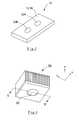
- FIG. 4is a perspective view of a heat dissipating component in the form of a heat sink having a cylindrical insert.
- FIG. 5is a section view taken along line 5 — 5 of FIG. 4 .
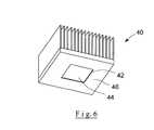
- FIG. 6is a view similar to FIG. 4 of a heat sink having a square insert.
- FIG. 7is a perspective view of a larger scale rectangular heat sink having a rectangular or square insert.
- FIG. 8is a perspective view of a pin-fin heat sink having a cylindrical insert.
- FIG. 9is a perspective view of a pin-fin heat sink having a square insert.
- the present inventionis directed to heat dissipating components constructed from a graphite planar element having a core or insert of high thermal conductivity placed in a cavity in the graphite element.
- Graphiteis a crystalline form of carbon comprising atoms covalently bonded in flat layered planes with weaker bonds between the planes.
- an intercalantof, e.g. a solution of sulfuric and nitric acid, the crystal structure of the graphite reacts to form a compound of graphite and the intercalant.
- the treated particles of graphiteare hereafter referred to as “particles of intercalated graphite.”
- the intercalant within the graphitedecomposes and volatilizes, causing the particles of intercalated graphite to expand in dimension as much as about 80 or more times its original volume in an accordion-like fashion in the “c” direction, i.e. in the direction perpendicular to the crystalline planes of the graphite.
- the exfoliated graphite particlesare vermiform in appearance, and are therefore commonly referred to as worms.
- the wormsmay be compressed together into flexible sheets that, unlike the original graphite flakes, can be formed and cut into various shapes and provided with small transverse openings by deforming mechanical impact.
- d(002)is the spacing between the graphitic layers of the carbons in the crystal structure measured in Angstrom units.
- the spacing d between graphite layersis measured by standard X-ray diffraction techniques.
- the positions of diffraction peaks corresponding to the (002), (004) and (006) Miller Indicesare measured, and standard least-squares techniques are employed to derive spacing which minimizes the total error for all of these peaks.
- highly graphitic carbonaceous materialsinclude natural graphites from various sources, as well as other carbonaceous materials such as carbons prepared by chemical vapor deposition and the like. Natural graphite is most preferred.
- the graphite starting materials used in the present inventionmay contain non-carbon components so long as the crystal structure of the starting materials maintains the required degree of graphitization and they are capable of exfoliation.
- any carbon-containing material, the crystal structure of which possesses the required degree of graphitization and which can be exfoliated,is suitable for use with the present invention.
- Such graphitepreferably has an ash content of less than twenty weight percent. More preferably, the graphite employed for the present invention will have a purity of at least about 94%. In the most preferred embodiment, the graphite employed will have a purity of at least about 98%.
- Shane et al.A common method for manufacturing graphite sheet is described by Shane et al. in U.S. Pat. No. 3,404,061, the disclosure of which is incorporated herein by reference.
- natural graphite flakesare intercalated by dispersing the flakes in a solution containing e.g., a mixture of nitric and sulfuric acid, advantageously at a level of about 20 to about 300 parts by weight of intercalant solution per 100 parts by weight of graphite flakes (pph).
- the intercalation solutioncontains oxidizing and other intercalating agents known in the art.
- Examplesinclude those containing oxidizing agents and oxidizing mixtures, such as solutions containing nitric acid, potassium chlorate, chromic acid, potassium permanganate, potassium chromate, potassium dichromate, perchloric acid, and the like, or mixtures, such as for example, concentrated nitric acid and chlorate, chromic acid and phosphoric acid, sulfuric acid and nitric acid, or mixtures of a strong organic acid, e.g. trifluoroacetic acid, and a strong oxidizing agent soluble in the organic acid.
- an electric potentialcan be used to bring about oxidation of the graphite.
- Chemical species that can be introduced into the graphite crystal using electrolytic oxidationinclude sulfuric acid as well as other acids.
- the intercalating agentis a solution of a mixture of sulfuric acid, or sulfuric acid and phosphoric acid, and an oxidizing agent, i.e. nitric acid, perchloric acid, chromic acid, potassium permanganate, hydrogen peroxide, iodic or periodic acids, or the like.
- the intercalation solutionmay contain metal halides such as ferric chloride, and ferric chloride mixed with sulfuric acid, or a halide, such as bromine as a solution of bromine and sulfuric acid or bromine in an organic solvent.
- the quantity of intercalation solutionmay range from about 20 to about 150 pph and more typically about 50 to about 120 pph. After the flakes are intercalated, any excess solution is drained from the flakes and the flakes are water-washed. Alternatively, the quantity of the intercalation solution may be limited to between about 10 and about 50 pph, which permits the washing step to be eliminated as taught and described in U.S. Pat. No. 4,895,713, the disclosure of which is also herein incorporated by reference.
- the particles of graphite flake treated with intercalation solutioncan optionally be contacted, e.g. by blending, with a reducing organic agent selected from alcohols, sugars, aldehydes and esters which are reactive with the surface film of oxidizing intercalating solution at temperatures in the range of 25° C. and 125° C.
- a reducing organic agentselected from alcohols, sugars, aldehydes and esters which are reactive with the surface film of oxidizing intercalating solution at temperatures in the range of 25° C. and 125° C.
- Suitable specific organic agentsinclude hexadecanol, octadecanol, 1-octanol, 2-octanol, decylalcohol, 1,10 decanediol, decylaldehyde, 1-propanol, 1,3 propanediol, ethyleneglycol, polypropylene glycol, dextrose, fructose, lactose, sucrose, potato starch, ethylene glycol monostearate, diethylene glycol dibenzoate, propylene glycol monostearate, glycerol monostearate, dimethyl oxylate, diethyl oxylate, methyl formate, ethyl formate, ascorbic acid and lignin-derived compounds, such as sodium lignosulfate.
- the amount of organic reducing agentis suitably from about 0.5 to 4% by weight of the particles of graphite flake.
- an expansion aid applied prior to, during or immediately after intercalationcan also provide improvements. Among these improvements can be reduced exfoliation temperature and increased expanded volume (also referred to as “worm volume”).
- An expansion aid in this contextwill advantageously be an organic material sufficiently soluble in the intercalation solution to achieve an improvement in expansion. More narrowly, organic materials of this type that contain carbon, hydrogen and oxygen, preferably exclusively, may be employed. Carboxylic acids have been found especially effective.
- a suitable carboxylic acid useful as the expansion aidcan be selected from aromatic, aliphatic or cycloaliphatic, straight chain or branched chain, saturated and unsaturated monocarboxylic acids, dicarboxylic acids and polycarboxylic acids which have at least 1 carbon atom, and preferably up to about 15 carbon atoms, which is soluble in the intercalation solution in amounts effective to provide a measurable improvement of one or more aspects of exfoliation.
- Suitable organic solventscan be employed to improve solubility of an organic expansion aid in the intercalation solution.
- saturated aliphatic carboxylic acidsare acids such as those of the formula H(CH 2 ) n COOH wherein n is a number of from 0 to about 5, including formic, acetic, propionic, butyric, pentanoic, hexanoic, and the like.
- the anhydrides or reactive carboxylic acid derivativessuch as alkyl esters can also be employed.
- alkyl estersare methyl formate and ethyl formate.
- Sulfuric acid, nitric acid and other known aqueous intercalantshave the ability to decompose formic acid, ultimately to water and carbon dioxide.
- dicarboxylic acidsare aliphatic dicarboxylic acids having 2-12 carbon atoms, in particular oxalic acid, fumaric acid, malonic acid, maleic acid, succinic acid, glutaric acid, adipic acid, 1,5-pentanedicarboxylic acid, 1,6-hexanedicarboxylic acid, 1,10-decanedicarboxylic acid, cyclohexane-1,4-dicarboxylic acid and aromatic dicarboxylic acids such as phthalic acid or terephthalic acid.
- alkyl estersare dimethyl oxylate and diethyl oxylate.
- Representative of cycloaliphatic acidsis cyclohexane carboxylic acid and of aromatic carboxylic acids are benzoic acid, naphthoic acid, anthranilic acid, p-aminobenzoic acid, salicylic acid, o-, m- and p-tolyl acids, methoxy and ethoxybenzoic acids, acetoacetamidobenzoic acids and, acetamidobenzoic acids, phenylacetic acid and naphthoic acids.
- hydroxy aromatic acidsare hydroxybenzoic acid, 3-hydroxy-1-naphthoic acid, 3-hydroxy-2-naphthoic acid, 4-hydroxy-2-naphthoic acid, 5-hydroxy-1-naphthoic acid, 5-hydroxy-2-naphthoic acid, 6-hydroxy-2-naphthoic acid and 7-hydroxy-2-naphthoic acid.
- Prominent among the polycarboxylic acidsis citric acid.
- the intercalation solutionwill be aqueous and will preferably contain an amount of expansion aid of from about 1 to 10%, the amount being effective to enhance exfoliation.
- the expansion aidcan be admixed with the graphite by suitable means, such as a V-blender, typically in an amount of from about 0.2% to about 10% by weight of the graphite flake.
- the blendAfter intercalating the graphite flake, and following the blending of the intercalant coated intercalated graphite flake with the organic reducing agent, the blend is exposed to temperatures in the range of 25° to 125° C. to promote reaction of the reducing agent and intercalant coating.
- the heating periodis up to about 20 hours, with shorter heating periods, e.g., at least about 10 minutes, for higher temperatures in the above-noted range. Times of one half hour or less, e.g., on the order of 10 to 25 minutes, can be employed at the higher temperatures.
- the thus treated particles of graphiteare sometimes referred to as “particles of intercalated graphite.”
- the particles of intercalated graphiteUpon exposure to high temperature, e.g. temperatures of at least about 160° C. and especially about 700° C. to 1000° C. and higher, the particles of intercalated graphite expand as much as about 80 to 1000 or more times their original volume in an accordion-like fashion in the c-direction, i.e. in the direction perpendicular to the crystalline planes of the constituent graphite particles.
- the expanded, i.e. exfoliated, graphite particlesare vermiform in appearance, and are therefore commonly referred to as worms.
- the wormsmay be compressed together into flexible sheets that, unlike the original graphite flakes, can be formed and cut into various shapes and provided with small transverse openings by deforming mechanical impact as hereinafter described.
- Flexible graphite sheet and foilare coherent, with good handling strength, and are suitably compressed, e.g. by roll-pressing, to a thickness of about 0.075 mm to 3.75 mm and a typical density of about 0.1 to 1.5 grams per cubic centimeter (g/cm 3 ).
- ceramic additivescan be blended with the intercalated graphite flakes as described in U.S. Pat. No. 5,902,762 (which is incorporated herein by reference) to provide enhanced resin impregnation in the final flexible graphite product.
- the additivesinclude ceramic fiber particles having a length of about 0.15 to 1.5 millimeters. The width of the particles is suitably from about 0.04 to 0.004 mm.
- the ceramic fiber particlesare non-reactive and non-adhering to graphite and are stable at temperatures up to about 1100° C., preferably about 1400° C. or higher.
- Suitable ceramic fiber particlesare formed of macerated quartz glass fibers, carbon and graphite fibers, zirconia, boron nitride, silicon carbide and magnesia fibers, naturally occurring mineral fibers such as calcium metasilicate fibers, calcium aluminum silicate fibers, aluminum oxide fibers and the like.
- planar graphite elements of the heat dissipating components described beloware preferably constructed from a laminated resin impregnated graphite material in the manner set forth in U.S. patent application Ser. No. 09/943,131, filed Aug. 31, 2001 of Norley et al. entitled “LAMINATES PREPARED FROM IMPREGNATED FLEXIBLE GRAPHITE SHEETS”, assigned to the assignee of the present invention, the details of which are incorporated herein by reference.
- thermosetting resinsuch as an epoxy, acrylic or phenolic resin system.
- Suitable epoxy resinsinclude diglycidyl ether of bisphenol A (DGEBA) resin systems; other multifunctional epoxy resins systems are also suitable for use in the present invention.
- Suitable phenolic resin systemsinclude those containing resole and novolak resins.
- the sheetsare then calendered to a thickness of about 0.35 mm to 0.5 mm, at which time the calendered, epoxy impregnated flexible mats have a density of about 1.4 g/cm 3 to about 1.9 g/cm 3 .
- the amount of resin within the epoxy impregnated graphite sheetsshould be an amount sufficient to ensure that the final assembled and cured layered structure is dense and cohesive, yet the anisotropic thermal conductivity associated with a densified graphite structure has not been adversely impacted.
- Suitable resin contentis preferably at least about 3% by weight, more preferably from about 5% to about 35% by weight depending on the characteristics desired in the final product.
- the flexible graphite sheetis passed through a vessel and impregnated with the resin system from, e.g. spray nozzles, the resin system advantageously being “pulled through the mat” by means of a vacuum chamber.
- the resin systemis solvated to facilitate application into the flexible graphite sheet.
- the resinis thereafter preferably dried, reducing the tack of the resin and the resin-impregnated sheet.
- the impregnated sheetsare cut to suitable-sized pieces which are stacked together and placed in a press, where they are cured at an elevated temperature.
- the temperatureshould be sufficient to ensure that the lamellar structure is densified at the curing pressure, improving the anisotropy of the structure and hence its thermal properties as a heat dissipating device. Generally, this will require a temperature of from about 150° C. to 200° C.
- the pressure employed for curingwill be somewhat a function of the temperature utilized, but will be sufficient to ensure that the lamellar structure is densified without adversely impacting the thermal properties of the structure. Generally, for convenience of manufacture, the minimum required pressure to densify the structure to the required degree will be utilized.
- Such a pressurewill generally be from 1000 to 3000 pounds per square inch (psi).
- the curing timemay vary depending on the resin system and the temperature and pressure employed, but generally will range from 0.5 hours to 2 hours. After curing is complete, the composites are seen to have a density of from about 1.8 g/cm 3 to 2.0 g/cm 3 .
- the resin present in the impregnated sheetscan act as the adhesive for the composite material.
- the calendered, impregnated, flexible graphite sheetsare coated with an adhesive before the flexible sheets are stacked and cured.
- Suitable adhesivesinclude epoxy-, acrlylic- and phenolic-based resins.
- Phenolic resins found especially useful in the practice of the present inventioninclude phenolic-based resin systems including resole and novolak phenolics.
- non-graphite layersmay be included in the pre-pressed stack.
- Such non-graphite layersmay include metals, plastics or other non-metallics such as fiberglass or ceramics.
- the epoxy polymer in the impregnated graphite sheetsis sufficient to, upon curing, adhesively bond the non-graphite as well as the impregnated graphite layers of the structure into place.
- Graphite sheets with a weight per unit area of 70 mg/cm 2 with dimensions of approximately 30 cm by 30 cmwere impregnated with epoxy such that the resulting calendered mats were 12 weight % epoxy.
- the epoxy employedwas a diglycidyl ether of bisphenol A (DGEBA) elevated temperature cure formulation and the impregnation procedures involved saturation with an acetone-resin solution followed by drying at approximately 80° C.
- the sheetswere then calendered from a thickness of approximately 7 mm to a thickness of approximately 0.4 mm and a density of 1.63 g/cm 3 .
- the calendered, impregnated sheetswere then cut into disks with a diameter of approximately 50 mm and the disks were stacked 46 layers high.
- the resultant laminatehad a density of 1.90 g/cm 3 , a flexural strength of 8000 psi, a Young's modules of 7.5 Msi (millions of pounds per square inch) and an in plane resistivity of 6 microhm.
- the in-plane and through-thickness thermal conductivity valueswere 396 W/m ⁇ ° C. and 6.9 W/m ⁇ ° C., respectively.
- the laminatesexhibited superior machinability, had a continuous pore free surface with a smooth finish and were suitable for use in electronic thermal management devices.
- the highly anisotropic thermal conductivityresulted in a structure highly adapted for use in piping heat away from sensitive electronics and into a heat sink.
- the density of the materialapproximately 1.94 g/cm 3
- the density of the materialis considerably below aluminum (2.7 g/cm 3 ) and much less than copper (8.96 g/cm 3 ).
- the specific thermal conductivity (that is, the ratio of thermal conductivity to density) of the graphite laminateis about three times that of aluminum and about four to six times that of copper.
- the laminated graphite materials suitable for use with the present inventionare not limited to those specific ones described above, and may for example include a laminate comprised of layers of pyrolytic graphite sheet such as that manufactured by Matsushita Electric Components Co., Ltd. Ceramic Division, 1006 Kadoma, Osaka, Japan under the trade name Panasonic “PGS”® Graphite Sheet.
- the system 10is in the form of a heat spreader 12 assembled with an electronic device 14 , which may also be referred to as a heat source 14 .
- the heat spreader 14includes an anisotropic graphite planar element 16 having a relatively high thermal conductivity in the plane of the planar element 16 along dimensions x and y and having a relatively low thermal conductivity across a thickness 18 of the planar element in a direction z normal to the plane defined by dimensions x and y.
- the planar element 16has a cylindrical cavity 20 defined therein, and preferably defined entirely through the thickness 18 . It will be understood, however, that it is possible for the cavity 20 to only extend partially into the thickness 18 .
- the heat spreader 12includes a core or insert 22 received in the cavity 20 .
- the core 22is preferably constructed of an isotropic core material, preferably a metal such as copper or aluminum In some embodiments, however, the core 22 could be constructed of an anisotropic material such as the graphite materials described herein, wherein the core is constructed so that the high thermal conductivity direction of the anisotropic material (commonly referred to as the “a” axes) is generally parallel to the z axis of the heat spreader shown in FIGS. 1 and 2.
- the planar element 16is preferably constructed from a laminated graphite material like that described above, wherein a plurality of resin impregnated graphite sheets are stacked and compressed together to form a rigid planar graphite element 16 .
- Typical dimensions of the element 16 for a heat spreader devicewould have a length along the x axis on the order of 6 to 12 inches, a width along the y axis on the order of 6 to 12 inches, and a thickness 18 along the z axis on the order of 1 ⁇ 2 inch.
- Typical dimensions of the cylindrical cavity 20would be a diameter of from 1 to 11 ⁇ 2 inches.
- the electronic device 14has a top surface 24 which may also be referred to as a heat conducting surface or heat transmitting surface 24 .
- the core 22has a heat receiving surface 26 which is operatively engaged with the surface 24 of the electronic device 14 in the conventional manner, which may include the use of a thin thermal interface 25 , or a layer of phase change material or thermal grease therebetween.
- the thermal interface 25may be, for example, a thin layer of flexible graphite material.
- core 22 and cavity 20are shown in FIGS. 1 and 2 as being cylindrical, they could be of any shape including circular, square, rectangular or other shape.
- the cylindrical shapemay be preferred due to its ease of machining.
- the heat receiving surface 26 of core 22is preferably larger than the heat transmitting surface 24 of device 14 so that the heat receiving surface 26 is in operative contact with and covers the entire top surface 24 of electronic device 14 . Otherwise, if a portion of the top surface 24 of electronic device 14 were covered by the graphite material 16 , the graphite material would not transfer heat as effectively in the z direction and would cause the temperature of device 14 to rise.
- FIG. 3shows an alternative embodiment of the apparatus 10 having a plurality of such inserts designated as 22 A and 22 B.
- Table Icompares the performance of the apparatus shown in FIGS. 1 and 2 for different material combinations. This data was generated by numerical modeling.
- design option #1 of Table Ian all copper heat spreader is shown for comparison.
- design option #2an all graphite heat spreader is shown for comparison where the highly conducting “a” axes of the graphite are aligned with the x and y axes of the heat spreader component.
- Option #2is the graphite spreader without any insert.
- Design option #3shows the present invention utilizing a graphite planar element with a copper insert.
- Design options #4 and #5illustrate graphite planar elements with graphite inserts with the high conductivity direction of the graphite oriented in a direction perpendicular to the plane of the spreader. Both design options #4 and #5 perform nearly as well as the copper insert of design option #3 without the added weight of the copper insert.
- T maxis the hottest temperature on the electronic device for the conditions modeled; lower temperatures are indicative of better performance by the heat dissipating component.
- R sarepresents the thermal resistance of the heat dissipating component, and again lower numbers are indicative of better performance by the heat dissipating component.
- the numbers for thermal conductivity for graphite materialsrepresent conductivity for each of the x, y and z directions and thus indicate the orientation of the anisotropic graphite; the higher numbers correspond to the directions of relatively high thermal conductivity.
- FIGS. 4 through 9various embodiments of the invention are shown in the context of heat sinks rather than heat spreaders.
- FIG. 4a perspective view is thereshown of a finned heat sink 30 having a cylindrical insert 32 .
- FIG. 5shows a cross-section view along line 5 — 5 of FIG. 4 for a finned heat sink 30 having a planar graphite base plate 34 with a plurality of graphite fins 36 .
- the anisotropic graphite material of base plate 34has its high conductivity directions aligned with the x and y axes.
- the fins 36are preferably separate elements with their high conductivity directions including the z direction. Fins 36 are received in grooves 35 machined in base plate 34 and are held in place therein by an epoxy resin or other suitable bonding material.
- Base plate 34has a cavity 38 extending partially therethrough in the z direction. Core 32 is received in cavity 34 .
- Design option #1is for a pure copper heat sink without any insert.
- Design #2is for a pure aluminum heat sink without any insert.
- Design option #3is for a pure graphite heat sink without any insert.
- the graphite orientation of design option #3has the high conductivity of the base plate parallel to the plane of the fins.
- Design #4is representative of the present invention wherein the heat sink is constructed of graphite with a copper insert 32 , as illustrated in FIG. 5 .
- the graphite orientation of the base plate in design option #4has the high conductivity in the x and y directions.
- the performance of the present invention utilizing a graphite heat sink with a copper insertis almost as good as that of a pure copper heat sink and is far superior to either a pure aluminum or pure graphite heat sink.
- the heat sink 40differs in that it has a rectangular insert 42 received within a rectangular cavity 44 in the base plate 46 .
- FIG. 7shows still a further alternative embodiment of a heat sink designated by the numeral 50 .
- the heat sink in FIG. 7is one designed for large size electronic chips.
- the heat sink 50has a base plate 52 with fins 54 .
- a square insert 56is received within a square cavity 58 defined through the base plate 52 .
- the data shown in the following Table IIIcompares the performance of a heat sink constructed in accordance with FIG. 7 with a prior art aluminum heat sink having a copper base (design #1).
- the design option #1is like that being currently sold by Radian Company, 2160 Walsh Avenue, Santa Clara, Calif. 95050; it is an aluminum heat sink with a partially hollowed out base filled with a copper plug.
- Design option #2is in accordance with the present invention having a graphite heat sink 50 with graphite base plate 52 and graphite fins 54 and a copper insert 56 . As shown by Table III, the performance of the graphite heat sink with copper insert of the present invention is far superior to that of the aluminum and copper heat sink of design option #1.
- FIGS. 8 and 9show perspective views of another type of heat sink known as a “pin-fin” heat sink.
- FIG. 8shows a pin-fin heat sink 60 having a base plate 62 and a plurality of pin-fins 64 .
- a cylindrical cavity 66 in the base plate 62contains a cylindrical insert 68 .
- FIG. 9shows a pin-fin heat sink 70 which is similar except that it utilizes a square or rectangular insert 72 .
- Table IVshows the performance of a pin-fin heat sink shaped like that of FIG. 8, with design options #1 and #2 being conventional prior art aluminum or copper heat sinks, and with option #3 showing the performance of the present invention utilizing a graphite heat sink with a copper insert 68 .
- the insertsmay be placed in the cavities of the heat dissipating components in several different ways.
- One preferred methodis to machine the insert to a very slightly larger diameter or dimension than the cavity machined into the graphite. Then the insert is cooled and it will contract to a diameter or dimension less than that of the cavity, allowing the insert to be placed inside the cavity. Upon warming of the insert to room temperature the insert will expand and fit snugly within the cavity with no adhesives or binders. If needed, a thin layer of thermal grease or phase change material or other lubricant can be coated onto the insert or on the inside of the cavity prior to inserting the insert.
- the heat dissipating elementprovides a thermal conductivity comparable to that of copper but with only one-fifth the weight of copper.
- Thismakes for lighter electronic devices, reducing the need for special mechanical fixtures and designs to hold heavy copper components.
- Reducing the mass of the heat dissipating componentreduces acceleration stress on electronics due to vibration, and allows for higher power to be dissipated than would otherwise be possible with conventional aluminum or copper heat sinks.
- Further design flexibilityis provided in that smaller heat sinks may be utilized to obtain the necessary cooling as compared to prior art designs.
Landscapes
- Engineering & Computer Science (AREA)
- Physics & Mathematics (AREA)
- Power Engineering (AREA)
- Thermal Sciences (AREA)
- Condensed Matter Physics & Semiconductors (AREA)
- General Physics & Mathematics (AREA)
- Computer Hardware Design (AREA)
- Microelectronics & Electronic Packaging (AREA)
- Chemical & Material Sciences (AREA)
- Materials Engineering (AREA)
- Mechanical Engineering (AREA)
- General Engineering & Computer Science (AREA)
- Cooling Or The Like Of Semiconductors Or Solid State Devices (AREA)
- Connections Effected By Soldering, Adhesion, Or Permanent Deformation (AREA)
- Non-Disconnectible Joints And Screw-Threaded Joints (AREA)
- Cooling Or The Like Of Electrical Apparatus (AREA)
Abstract
Description

| TABLE I | ||||
| Thermal Conductivity | ||||
| Design | Tmax | Rsa | and Graphite Orientation | |
| # | Option | (° C.) | (° C./W) | (W/m · ° C.) |
| 1 | Copper | 39.62 | 0.44 | |||
| 2 | Graphite | 43.97 | 0.55 | |||
| 3 | Graphite with | 39.77 | 0.44 | |||
| Copper Insert | ||||||
| 4 | Graphite with | 40.07 | 0.45 | X | Y | Z |
| Graphite Insert | 7 | 400 | 400 | |||
| 5 | Graphite with | 40.05 | 0.45 | X | Y | Z |
| Graphite Insert | 400 | 7 | 400 | |||
| TABLE II | ||||
| Thermal Conductivity | ||||
| Design | Tmax | Rsa | and Graphite Orientation | |
| # | Option | (° C.) | (°C./W) | (W/m · ° C.) |
| 1 | Copper | 71.7 | 0.61 | 391 |
| 2 | Aluminum | 82.1 | 0.79 | 209 |
| 3 | Pure-Graphite | 91.5 | 0.94 | X | Y | Z |
| 400 | 7 | 400 | ||||
| 4 | Graphite with | 73.7 | 0.65 | X | Y | Z |
| Copper Insert | 400 | 400 | 7 | |||
| TABLE III | ||||
| Tmax | Rsa | Weight | ||
| # | Design Option | (° C.) | (° C./W) | (kg) |
| 1 | Aluminum (with Copper Base) | 64.27 | 0.33 | 3.292 |
| (Power = 90 W) | ||||
| 2 | Graphite (with copper insert) | 55.21 | 0.22 | 1.647 |
| (Power = 90 W) | ||||
| TABLE IV | |||
| Tmax | Rsa | ||
| #1 | Design Option | (° C.) | (° C./W) |
| 1 | Aluminum | 82.13 | 1.89 |
| 2 | Copper | 77.08 | 1.683 |
| 3 | Graphite (Copper Insert) | 78.79 | 1.751 |
Claims (23)
Priority Applications (10)
| Application Number | Priority Date | Filing Date | Title |
|---|---|---|---|
| US10/015,459US6758263B2 (en) | 2001-12-13 | 2001-12-13 | Heat dissipating component using high conducting inserts |
| DK02786813.2TDK1454108T3 (en) | 2001-12-13 | 2002-11-27 | Heat-conducting component that uses high conductive inserts |
| EP02786813AEP1454108B1 (en) | 2001-12-13 | 2002-11-27 | Heat dissipating component using high conducting inserts |
| HK05110646.2AHK1078926B (en) | 2001-12-13 | 2002-11-27 | Heat dissipating component using high conducting inserts |
| AT02786813TATE460634T1 (en) | 2001-12-13 | 2002-11-27 | HEAT DISSIPATION COMPONENT USING HIGH CONDUCTION INSERTS |
| ES02786813TES2341643T3 (en) | 2001-12-13 | 2002-11-27 | HEAT DISSIPATION COMPONENT THAT USES HIGH DRIVING INSERTS. |
| CNB028280989ACN100380087C (en) | 2001-12-13 | 2002-11-27 | Heat dissipating component using high conducting inserts |
| PCT/US2002/038061WO2003052340A1 (en) | 2001-12-13 | 2002-11-27 | Heat dissipating component using high conducting inserts |
| AU2002351166AAU2002351166A1 (en) | 2001-12-13 | 2002-11-27 | Heat dissipating component using high conducting inserts |
| DE60235647TDE60235647D1 (en) | 2001-12-13 | 2002-11-27 | HIGH-LEADING INSERTS USING HEAT-LOSSING COMPONENT |
Applications Claiming Priority (1)
| Application Number | Priority Date | Filing Date | Title |
|---|---|---|---|
| US10/015,459US6758263B2 (en) | 2001-12-13 | 2001-12-13 | Heat dissipating component using high conducting inserts |
Publications (2)
| Publication Number | Publication Date |
|---|---|
| US20030116312A1 US20030116312A1 (en) | 2003-06-26 |
| US6758263B2true US6758263B2 (en) | 2004-07-06 |
Family
ID=21771534
Family Applications (1)
| Application Number | Title | Priority Date | Filing Date |
|---|---|---|---|
| US10/015,459Expired - LifetimeUS6758263B2 (en) | 2001-12-13 | 2001-12-13 | Heat dissipating component using high conducting inserts |
Country Status (9)
| Country | Link |
|---|---|
| US (1) | US6758263B2 (en) |
| EP (1) | EP1454108B1 (en) |
| CN (1) | CN100380087C (en) |
| AT (1) | ATE460634T1 (en) |
| AU (1) | AU2002351166A1 (en) |
| DE (1) | DE60235647D1 (en) |
| DK (1) | DK1454108T3 (en) |
| ES (1) | ES2341643T3 (en) |
| WO (1) | WO2003052340A1 (en) |
Cited By (78)
| Publication number | Priority date | Publication date | Assignee | Title |
|---|---|---|---|---|
| US20040119161A1 (en)* | 2002-12-18 | 2004-06-24 | Sumitomo Electric Industries, Ltd. | Package for housing semiconductor chip, fabrication method thereof and semiconductor device |
| US20040223303A1 (en)* | 2003-05-06 | 2004-11-11 | Hornung Craig Warren | Dual material heat sink core assembly |
| US20040264137A1 (en)* | 2003-06-26 | 2004-12-30 | Trautman Mark A | Low noise heatsink |
| US20050013119A1 (en)* | 2003-07-17 | 2005-01-20 | Sanjay Misra | Thermal diffusion apparatus |
| US20050016714A1 (en)* | 2003-07-09 | 2005-01-27 | Chung Deborah D.L. | Thermal paste for improving thermal contacts |
| US20050057897A1 (en)* | 2003-09-16 | 2005-03-17 | Shiu Hsiung Ming | Heat dissipating device with heat conductive posts |
| US20050079355A1 (en)* | 2003-10-14 | 2005-04-14 | Timothy Clovesko | Heat spreader for emissive display device |
| US20050088823A1 (en)* | 2003-10-22 | 2005-04-28 | Kabadi Ashok N. | Variable density graphite foam heat sink |
| US20050094375A1 (en)* | 2003-11-05 | 2005-05-05 | Chiang Tsai L. | Integrated heat dissipating device with curved fins |
| US20050142317A1 (en)* | 2003-10-14 | 2005-06-30 | Timothy Clovesko | Heat spreader for display device |
| US20050167084A1 (en)* | 2003-01-10 | 2005-08-04 | International Business Machines Corporation | Graphite-based heat sinks and method and apparatus for the manufacture thereof |
| US20050180111A1 (en)* | 2004-02-18 | 2005-08-18 | Bamesberger Brett E. | Low thermal stress composite heat sink assembly |
| US20050189647A1 (en)* | 2002-10-11 | 2005-09-01 | Chien-Min Sung | Carbonaceous composite heat spreader and associated methods |
| US20050199368A1 (en)* | 2004-03-11 | 2005-09-15 | Gonzales Christopher A. | Laminated fin heat sink for electronic devices |
| US20050238835A1 (en)* | 2004-04-24 | 2005-10-27 | Chien-Min Sung | Graphite composite thermal sealants and associated methods |
| US20060091532A1 (en)* | 2002-10-11 | 2006-05-04 | Chien-Min Sung | Carbonaceous composite heat spreader and associated methods |
| US20060098413A1 (en)* | 2003-10-14 | 2006-05-11 | Capp Joseph P | Heat spreader for display device |
| US20060109628A1 (en)* | 2004-11-19 | 2006-05-25 | Searby Tom J | Cooling apparatus for electronic devices |
| US20060113546A1 (en)* | 2002-10-11 | 2006-06-01 | Chien-Min Sung | Diamond composite heat spreaders having low thermal mismatch stress and associated methods |
| US20060171124A1 (en)* | 2005-01-28 | 2006-08-03 | Capp Joseph P | Heat spreader for display device |
| US20060185820A1 (en)* | 2005-02-23 | 2006-08-24 | Asia Vital Component Co., Ltd. | Radiator structure |
| US20060227508A1 (en)* | 2005-04-08 | 2006-10-12 | Tyco Electronics Corporation | Heat sink assembly |
| US20060290251A1 (en)* | 2005-06-27 | 2006-12-28 | Shives Gary D | Display device having improved properties |
| US20060290875A1 (en)* | 2005-06-27 | 2006-12-28 | Shives Gary D | Optimized frame system for a display device |
| US20060292461A1 (en)* | 2005-06-27 | 2006-12-28 | Shives Gary D | Optimized frame system for a liquid crystal display device |
| US7160619B2 (en)* | 2003-10-14 | 2007-01-09 | Advanced Energy Technology Inc. | Heat spreader for emissive display device |
| US20070053168A1 (en)* | 2004-01-21 | 2007-03-08 | General Electric Company | Advanced heat sinks and thermal spreaders |
| US20070076422A1 (en)* | 2005-09-30 | 2007-04-05 | Valeo Vision | Lighting and/or signaling device for a motor vehicle incorporating a material having thermal anisotropy |
| US20070103875A1 (en)* | 2005-11-04 | 2007-05-10 | Reis Bradley E | Cycling LED Heat Spreader |
| US20070102142A1 (en)* | 2005-11-04 | 2007-05-10 | Reis Bradley E | Heat spreaders with vias |
| US20070139895A1 (en)* | 2005-11-04 | 2007-06-21 | Reis Bradley E | LED with integral thermal via |
| US20070170581A1 (en)* | 2002-10-11 | 2007-07-26 | Chien-Min Sung | Silicon-diamond composite heat spreader and associated methods |
| US20070246824A1 (en)* | 2006-03-28 | 2007-10-25 | Gwin Paul J | Heat sink design using clad metal |
| US20070257359A1 (en)* | 2006-05-03 | 2007-11-08 | Reis Bradley E | Thermal Management Device For A Memory Module |
| US20070297140A1 (en)* | 2006-06-26 | 2007-12-27 | International Business Machines Corporation | Modular heat sink fin modules for cpu |
| US20080007917A1 (en)* | 2006-07-06 | 2008-01-10 | Kao Wei-Chun | Heat dissipator assembly |
| US20080030960A1 (en)* | 2005-07-05 | 2008-02-07 | International Business Machines Corporation | Anisotropic heat spreading apparatus and method for semiconductor devices |
| US20080044624A1 (en)* | 2006-08-18 | 2008-02-21 | Chin-Fu Horng | Complex architecture for dispersing heat |
| US20080085389A1 (en)* | 2003-10-14 | 2008-04-10 | Julian Norley | Heat spreader for plasma display panel |
| US7375288B1 (en)* | 2004-07-30 | 2008-05-20 | Intel Corp. | Apparatuses and methods for improving ball-grid-array solder joint reliability |
| US7385819B1 (en) | 2005-06-27 | 2008-06-10 | Graftech International Holdings Inc. | Display device |
| US20080274358A1 (en)* | 2005-12-02 | 2008-11-06 | Christopher John Spacie | Carbon Materials |
| US20090032218A1 (en)* | 2007-07-31 | 2009-02-05 | Adc Telecommunications, Inc. | Apparatus for transferring between two heat conducting surfaces |
| US20090032234A1 (en)* | 2007-07-31 | 2009-02-05 | Adc Telecommunications, Inc. | Apparatus for transferring heat in a fin of a heat sink |
| US20090032217A1 (en)* | 2007-07-31 | 2009-02-05 | Adc Telecommunications, Inc. | Apparatus for spreading heat over a finned surface |
| US20090040719A1 (en)* | 2007-08-06 | 2009-02-12 | Chin-Fu Horng | Graphite heat dissipation apparatus and clamping frame for clamping graphite heat dissipation fin module |
| US20090067132A1 (en)* | 2007-09-07 | 2009-03-12 | Specialty Minerals (Michigan) Inc. | Heat spreader and method of making the same |
| US20090141452A1 (en)* | 2007-11-30 | 2009-06-04 | Adc Telecommunications, Inc. | Apparatus for directing heat to a heat spreader |
| US20090139698A1 (en)* | 2007-12-03 | 2009-06-04 | Watronx, Inc. (Aka Onscreen Technologies, Inc.) | Carbon-based waterlock with attached heat-exchanger for cooling of electronic devices |
| US20090169410A1 (en)* | 2007-12-31 | 2009-07-02 | Slaton David S | Method of forming a thermo pyrolytic graphite-embedded heatsink |
| US20090165302A1 (en)* | 2007-12-31 | 2009-07-02 | Slaton David S | Method of forming a heatsink |
| US20090279276A1 (en)* | 2008-05-08 | 2009-11-12 | Toyota Jidosha Kabushiki Kaisha | Electronic component |
| US7791188B2 (en) | 2007-06-18 | 2010-09-07 | Chien-Min Sung | Heat spreader having single layer of diamond particles and associated methods |
| US20100243230A1 (en)* | 2009-03-25 | 2010-09-30 | Wah Hong Industrial Corp. | Heat-dissipating device including a plating metal layer |
| US20100321890A1 (en)* | 2009-06-19 | 2010-12-23 | General Electric Company | Avionics Chassis |
| US20100321892A1 (en)* | 2009-06-19 | 2010-12-23 | General Electric Company | Avionics Chassis |
| US20100320450A1 (en)* | 2008-02-21 | 2010-12-23 | Hiroshi Fujioka | Semiconductor substrate, semiconductor device, light emitting device and electronic device |
| US20100321891A1 (en)* | 2009-06-19 | 2010-12-23 | General Electric Company | Avionics Chassis |
| US20100319948A1 (en)* | 2009-06-19 | 2010-12-23 | General Electric Company | Avionics Chassis |
| US7889502B1 (en) | 2005-11-04 | 2011-02-15 | Graftech International Holdings Inc. | Heat spreading circuit assembly |
| WO2011039531A1 (en) | 2009-09-29 | 2011-04-07 | Morganite Electrical Carbon Limited | Graphitic body containing metallic inclusion |
| US20110132896A1 (en)* | 2009-12-08 | 2011-06-09 | Therm-X Of California | Heater plate with embedded hyper-conductive thermal diffusion layer for increased temperature rating and uniformity |
| US20110214851A1 (en)* | 2009-08-14 | 2011-09-08 | Wah Hong Industrial Corp. | Use of a graphite heat-dissipation device including a plating metal layer |
| US20110259570A1 (en)* | 2008-09-11 | 2011-10-27 | Nobuyuki Suzuki | Heat radiator composed of a combination of a graphite-metal complex and an aluminum extruded material |
| US20110278629A1 (en)* | 2009-11-13 | 2011-11-17 | Uni-Light Llc | Led thermal management |
| US20130160980A1 (en)* | 2010-09-10 | 2013-06-27 | Osram Ag | Making method for cooling body, cooling body and lighting device comprising the cooling body |
| US8531026B2 (en) | 2010-09-21 | 2013-09-10 | Ritedia Corporation | Diamond particle mololayer heat spreaders and associated methods |
| US8778784B2 (en) | 2010-09-21 | 2014-07-15 | Ritedia Corporation | Stress regulated semiconductor devices and associated methods |
| US9006086B2 (en) | 2010-09-21 | 2015-04-14 | Chien-Min Sung | Stress regulated semiconductor devices and associated methods |
| US20150219327A1 (en)* | 2014-01-31 | 2015-08-06 | Christie Digital Systems Usa, Inc. | Light emitting device with a heat sink composed of two materials |
| US20160095201A1 (en)* | 2014-09-30 | 2016-03-31 | Samsung Electro-Mechanics Co., Ltd. | Circuit board comprising heat transfer structure |
| US9437515B2 (en) | 2013-03-22 | 2016-09-06 | International Business Machines Corporation | Heat spreading layer with high thermal conductivity |
| US20170314871A1 (en)* | 2016-04-29 | 2017-11-02 | Intel Corporation | Wickless capillary driven constrained vapor bubble heat pipes for application in heat sinks |
| US10090222B2 (en)* | 2017-02-17 | 2018-10-02 | Fuji Electric Co., Ltd. | Semiconductor device with heat dissipation and method of making same |
| US10206310B2 (en) | 2017-04-07 | 2019-02-12 | Toyota Motor Engineering & Manufacturing North America, Inc. | Electronics assemblies incorporating three-dimensional heat flow structures |
| US10347559B2 (en) | 2011-03-16 | 2019-07-09 | Momentive Performance Materials Inc. | High thermal conductivity/low coefficient of thermal expansion composites |
| US10969840B2 (en)* | 2015-11-16 | 2021-04-06 | Intel Corporation | Heat spreaders with interlocked inserts |
| US11355411B2 (en)* | 2018-02-07 | 2022-06-07 | Nec Platforms, Ltd. | Heat sink and assembly method for heat sink |
Families Citing this family (68)
| Publication number | Priority date | Publication date | Assignee | Title |
|---|---|---|---|---|
| JP4045241B2 (en)* | 2002-01-16 | 2008-02-13 | 富士通株式会社 | Heat sink with improved cooling capacity and semiconductor device including the heat sink |
| US7108055B2 (en) | 2002-03-29 | 2006-09-19 | Advanced Energy Technology Inc. | Optimized heat sink using high thermal conducting base and low thermal conducting fins |
| US20050155743A1 (en)* | 2002-06-28 | 2005-07-21 | Getz George Jr. | Composite heat sink with metal base and graphite fins |
| US7145125B2 (en) | 2003-06-23 | 2006-12-05 | Advanced Optical Technologies, Llc | Integrating chamber cone light using LED sources |
| US7521667B2 (en) | 2003-06-23 | 2009-04-21 | Advanced Optical Technologies, Llc | Intelligent solid state lighting |
| US7220485B2 (en) | 2003-09-19 | 2007-05-22 | Momentive Performance Materials Inc. | Bulk high thermal conductivity feedstock and method of making thereof |
| US20050072563A1 (en)* | 2003-10-03 | 2005-04-07 | Wang Chin Wen | Heat sink structure |
| US6982874B2 (en) | 2003-11-25 | 2006-01-03 | Advanced Energy Technology Inc. | Thermal solution for electronic devices |
| US7393587B2 (en)* | 2004-09-17 | 2008-07-01 | Graftech International Holdings Inc. | Sandwiched finstock |
| US20060070720A1 (en)* | 2004-09-17 | 2006-04-06 | Capp Joseph P | Heat riser |
| US7799428B2 (en) | 2004-10-06 | 2010-09-21 | Graftech International Holdings Inc. | Sandwiched thermal solution |
| CN1980558B (en)* | 2005-12-09 | 2011-09-28 | 鸿富锦精密工业(深圳)有限公司 | Liquid-cooling type radiating combination and liquid-cooling radiating apparatus |
| WO2007087090A2 (en)* | 2006-01-25 | 2007-08-02 | Advanced Energy Technology Inc. | Heat spreaders with vias |
| US20070204972A1 (en)* | 2006-03-01 | 2007-09-06 | Sensis Corporation | Method and apparatus for dissipating heat |
| FR2898668B1 (en) | 2006-03-15 | 2008-06-27 | Ferraz Date Ind Soc Par Action | HEAT EXCHANGER FOR COOLING AN ELECTRONIC COMPONENT AND METHOD FOR MANUFACTURING THE SAME |
| EP2021688B1 (en)* | 2006-05-05 | 2016-04-27 | Cree, Inc. | Lighting device |
| US20070267173A1 (en)* | 2006-05-22 | 2007-11-22 | Asia Vital Components Co., Ltd. | Radiator for heat sink device |
| US20080128067A1 (en)* | 2006-10-08 | 2008-06-05 | Momentive Performance Materials Inc. | Heat transfer composite, associated device and method |
| US20080085403A1 (en)* | 2006-10-08 | 2008-04-10 | General Electric Company | Heat transfer composite, associated device and method |
| US7794114B2 (en)* | 2006-10-11 | 2010-09-14 | Cree, Inc. | Methods and apparatus for improved heat spreading in solid state lighting systems |
| CN101536182B (en)* | 2006-11-02 | 2011-07-06 | 日本电气株式会社 | Semiconductor device |
| DE102006052220A1 (en)* | 2006-11-06 | 2008-05-08 | Patent-Treuhand-Gesellschaft für elektrische Glühlampen mbH | Motor vehicle headlight |
| US20080230208A1 (en)* | 2007-03-22 | 2008-09-25 | Claus Nygaard Rasmussen | Liquid Cooling System Cold Plate Assembly |
| JP2008287960A (en)* | 2007-05-16 | 2008-11-27 | Nec Lighting Ltd | Lighting device |
| US7845393B2 (en)* | 2007-11-06 | 2010-12-07 | Jiing Tung Tec. Metal Co., Ltd. | Thermal module |
| BE1017916A3 (en)* | 2007-12-31 | 2009-11-03 | Gebotech Bv | HEAT EXCHANGER. |
| US20090255660A1 (en)* | 2008-04-10 | 2009-10-15 | Metal Matrix Cast Composites, Llc | High Thermal Conductivity Heat Sinks With Z-Axis Inserts |
| US20090284933A1 (en)* | 2008-05-15 | 2009-11-19 | Edison Opto Corporation | Combination type heat dissipation module |
| US8963323B2 (en) | 2008-06-20 | 2015-02-24 | Alcatel Lucent | Heat-transfer structure |
| US20100008045A1 (en)* | 2008-07-09 | 2010-01-14 | Hong Fu Jin Precision Industry(Shenzhen) Co., Ltd | Heat sink |
| WO2010027504A1 (en)* | 2008-09-08 | 2010-03-11 | Materials And Electrochemical Research (Mer) Corporation | Machinable metal/diamond metal matrix composite compound structure and method of making same |
| US7740380B2 (en)* | 2008-10-29 | 2010-06-22 | Thrailkill John E | Solid state lighting apparatus utilizing axial thermal dissipation |
| US9718447B2 (en)* | 2009-02-02 | 2017-08-01 | Goodrich Corporation | Thermal management composite heat shield |
| US9179578B2 (en)* | 2009-08-25 | 2015-11-03 | Fuji Electric Co., Ltd. | Semiconductor module and heat radiation member |
| KR101250449B1 (en)* | 2009-09-07 | 2013-04-08 | 한국전자통신연구원 | Solid type heat dissipation device |
| CN101777620A (en)* | 2009-12-31 | 2010-07-14 | 深圳市蓝科电子有限公司 | High-power LED lead frame using graphite material as substrate, and preparation method |
| US20110186267A1 (en)* | 2010-02-01 | 2011-08-04 | Suna Display Co. | Heat transfer device with anisotropic thermal conducting micro structures |
| TWM395570U (en)* | 2010-08-19 | 2011-01-01 | guo-ren Zheng | Woodworking planer structure |
| WO2013090123A1 (en)* | 2011-12-12 | 2013-06-20 | Nikon Corporation | Thermal plate for environment and temperature control of motors used to move stages in lithography tools |
| US9425124B2 (en)* | 2012-02-02 | 2016-08-23 | International Business Machines Corporation | Compliant pin fin heat sink and methods |
| US9899120B2 (en) | 2012-11-02 | 2018-02-20 | Nanotek Instruments, Inc. | Graphene oxide-coated graphitic foil and processes for producing same |
| US9835390B2 (en) | 2013-01-07 | 2017-12-05 | Nanotek Instruments, Inc. | Unitary graphene material-based integrated finned heat sink |
| US10566482B2 (en) | 2013-01-31 | 2020-02-18 | Global Graphene Group, Inc. | Inorganic coating-protected unitary graphene material for concentrated photovoltaic applications |
| US10087073B2 (en)* | 2013-02-14 | 2018-10-02 | Nanotek Instruments, Inc. | Nano graphene platelet-reinforced composite heat sinks and process for producing same |
| EP2854170B1 (en) | 2013-09-27 | 2022-01-26 | Alcatel Lucent | A structure for a heat transfer interface and method of manufacturing the same |
| US20150096719A1 (en)* | 2013-10-04 | 2015-04-09 | Specialty Minerals (Michigan) Inc. | Apparatus for Dissipating Heat |
| US20150257249A1 (en)* | 2014-03-08 | 2015-09-10 | Gerald Ho Kim | Heat Sink With Protrusions On Multiple Sides Thereof And Apparatus Using The Same |
| DE102014006372A1 (en) | 2014-05-05 | 2015-11-05 | Gkn Sinter Metals Engineering Gmbh | Layers of a hydrogen storage and their production |
| GB2536689A (en)* | 2015-03-26 | 2016-09-28 | Inex Microtechnology Ltd | Carrier and insert |
| US10546797B2 (en)* | 2015-06-26 | 2020-01-28 | Kaneka Corporation | Heat transfer structure and manufacturing method therefore |
| WO2017062547A1 (en)* | 2015-10-06 | 2017-04-13 | Magna Seating Inc. | Thermally conductive padding |
| US9889624B2 (en) | 2015-10-09 | 2018-02-13 | Raytheon Company | Anisotropic thermal conduit |
| US20180047885A1 (en)* | 2016-08-10 | 2018-02-15 | GM Global Technology Operations LLC | Multi-material led heat sinks |
| CN108463090B (en)* | 2017-02-21 | 2023-12-29 | 东莞钱锋特殊胶粘制品有限公司 | Light-weight three-dimensional composite uniform temperature material |
| WO2019082371A1 (en)* | 2017-10-27 | 2019-05-02 | 日産自動車株式会社 | Semiconductor device |
| JP2019096702A (en)* | 2017-11-21 | 2019-06-20 | トヨタ自動車株式会社 | Cooler |
| JP2019096731A (en)* | 2017-11-22 | 2019-06-20 | トヨタ自動車株式会社 | Semiconductor device |
| US11152279B2 (en) | 2018-03-26 | 2021-10-19 | Raytheon Company | Monolithic microwave integrated circuit (MMIC) cooling structure |
| US10785863B2 (en) | 2018-04-09 | 2020-09-22 | Raytheon Company | Circuit support and cooling structure |
| US11075141B2 (en) | 2018-09-14 | 2021-07-27 | Raytheon Company | Module base with integrated thermal spreader and heat sink for thermal and structural management of high-performance integrated circuits or other devices |
| EP3726572B1 (en)* | 2019-04-16 | 2025-08-13 | ABB Schweiz AG | Heatsink assembly, method of manufacturing a heatsink assembly, and an electrical device |
| RU196433U1 (en)* | 2019-11-06 | 2020-02-28 | Акционерное общество "Концерн "Созвездие" | Thermal protection device for heat-generating electro-radio products |
| US11032947B1 (en) | 2020-02-17 | 2021-06-08 | Raytheon Company | Tailored coldplate geometries for forming multiple coefficient of thermal expansion (CTE) zones |
| DE112020007710T5 (en)* | 2020-10-21 | 2023-08-03 | Mitsubishi Electric Corporation | semiconductor device |
| CN113091059A (en)* | 2021-03-22 | 2021-07-09 | 武汉理工大学 | Anisotropic miniature flat burner |
| CN113048812A (en)* | 2021-04-25 | 2021-06-29 | 珠海格力电器股份有限公司 | Radiator and refrigeration equipment |
| US20240274488A1 (en)* | 2023-02-10 | 2024-08-15 | The Esab Group Inc. | Thermal conductive member for a heat sink |
| US20250212373A1 (en)* | 2023-12-22 | 2025-06-26 | Macdonald, Dettwiler And Associates Corporation | Apparatus and method for thermal management of high-power electronic components using graphite bars |
Citations (22)
| Publication number | Priority date | Publication date | Assignee | Title |
|---|---|---|---|---|
| US3678995A (en)* | 1970-06-22 | 1972-07-25 | Rca Corp | Support for electrical components and method of making the same |
| US4234638A (en)* | 1976-07-23 | 1980-11-18 | Nippon Carbon Co., Ltd. | Composite graphite sheets |
| US4782893A (en)* | 1986-09-15 | 1988-11-08 | Trique Concepts, Inc. | Electrically insulating thermally conductive pad for mounting electronic components |
| US4812792A (en) | 1983-12-22 | 1989-03-14 | Trw Inc. | High-frequency multilayer printed circuit board |
| US4878152A (en) | 1987-06-16 | 1989-10-31 | Thomson-Csf | Mounting for printed circuits forming a heat sink with controlled expansion |
| US5255738A (en)* | 1992-07-16 | 1993-10-26 | E-Systems, Inc. | Tapered thermal substrate for heat transfer applications and method for making same |
| US5287248A (en)* | 1991-04-17 | 1994-02-15 | E-Systems, Inc. | Metal matrix composite heat transfer device and method |
| US5316080A (en) | 1990-03-30 | 1994-05-31 | The United States Of America As Represented By The Administrator Of The National Aeronautics & Space Administration | Heat transfer device |
| US5366688A (en) | 1992-12-09 | 1994-11-22 | Iowa State University Research Foundation, Inc. | Heat sink and method of fabricating |
| US5542471A (en) | 1993-11-16 | 1996-08-06 | Loral Vought System Corporation | Heat transfer element having the thermally conductive fibers |
| US5660917A (en)* | 1993-07-06 | 1997-08-26 | Kabushiki Kaisha Toshiba | Thermal conductivity sheet |
| US5944097A (en)* | 1997-05-06 | 1999-08-31 | Northrop Grumman Corporation | Composite substrate carrier for high power electronic devices |
| US5958572A (en)* | 1997-09-30 | 1999-09-28 | Motorola, Inc. | Hybrid substrate for cooling an electronic component |
| US6027807A (en) | 1995-01-11 | 2000-02-22 | Matsushita Electric Industrial Co., Ltd. | Graphite cladding laminate structural material and a graphite device having said material |
| US6060166A (en)* | 1998-02-05 | 2000-05-09 | Raytheon Company | Flexible graphite fiber thermal shunt |
| US6075701A (en) | 1999-05-14 | 2000-06-13 | Hughes Electronics Corporation | Electronic structure having an embedded pyrolytic graphite heat sink material |
| US6131651A (en) | 1998-09-16 | 2000-10-17 | Advanced Ceramics Corporation | Flexible heat transfer device and method |
| US6141216A (en) | 1999-03-31 | 2000-10-31 | International Business Machines Corporation | Quick-release hinge joint for heat pipe |
| US6208513B1 (en) | 1995-01-17 | 2001-03-27 | Compaq Computer Corporation | Independently mounted cooling fins for a low-stress semiconductor package |
| US20020157819A1 (en)* | 2001-04-04 | 2002-10-31 | Julian Norley | Graphite-based thermal dissipation component |
| US6503626B1 (en)* | 2000-02-25 | 2003-01-07 | Graftech Inc. | Graphite-based heat sink |
| US6555223B2 (en)* | 2000-03-08 | 2003-04-29 | Sgl Technic, Inc. | Graphite structure with increased flexibility |
Family Cites Families (3)
| Publication number | Priority date | Publication date | Assignee | Title |
|---|---|---|---|---|
| JP3885246B2 (en)* | 1996-01-12 | 2007-02-21 | 松下電器産業株式会社 | Plasma display panel |
| US5902762A (en)* | 1997-04-04 | 1999-05-11 | Ucar Carbon Technology Corporation | Flexible graphite composite |
| CN2358558Y (en)* | 1998-12-07 | 2000-01-12 | 姜守仁 | Flexible heat-conducting pad |
- 2001
- 2001-12-13USUS10/015,459patent/US6758263B2/ennot_activeExpired - Lifetime
- 2002
- 2002-11-27EPEP02786813Apatent/EP1454108B1/ennot_activeExpired - Lifetime
- 2002-11-27AUAU2002351166Apatent/AU2002351166A1/ennot_activeAbandoned
- 2002-11-27CNCNB028280989Apatent/CN100380087C/ennot_activeExpired - Fee Related
- 2002-11-27DKDK02786813.2Tpatent/DK1454108T3/enactive
- 2002-11-27WOPCT/US2002/038061patent/WO2003052340A1/ennot_activeApplication Discontinuation
- 2002-11-27DEDE60235647Tpatent/DE60235647D1/ennot_activeExpired - Lifetime
- 2002-11-27ATAT02786813Tpatent/ATE460634T1/ennot_activeIP Right Cessation
- 2002-11-27ESES02786813Tpatent/ES2341643T3/ennot_activeExpired - Lifetime
Patent Citations (22)
| Publication number | Priority date | Publication date | Assignee | Title |
|---|---|---|---|---|
| US3678995A (en)* | 1970-06-22 | 1972-07-25 | Rca Corp | Support for electrical components and method of making the same |
| US4234638A (en)* | 1976-07-23 | 1980-11-18 | Nippon Carbon Co., Ltd. | Composite graphite sheets |
| US4812792A (en) | 1983-12-22 | 1989-03-14 | Trw Inc. | High-frequency multilayer printed circuit board |
| US4782893A (en)* | 1986-09-15 | 1988-11-08 | Trique Concepts, Inc. | Electrically insulating thermally conductive pad for mounting electronic components |
| US4878152A (en) | 1987-06-16 | 1989-10-31 | Thomson-Csf | Mounting for printed circuits forming a heat sink with controlled expansion |
| US5316080A (en) | 1990-03-30 | 1994-05-31 | The United States Of America As Represented By The Administrator Of The National Aeronautics & Space Administration | Heat transfer device |
| US5287248A (en)* | 1991-04-17 | 1994-02-15 | E-Systems, Inc. | Metal matrix composite heat transfer device and method |
| US5255738A (en)* | 1992-07-16 | 1993-10-26 | E-Systems, Inc. | Tapered thermal substrate for heat transfer applications and method for making same |
| US5366688A (en) | 1992-12-09 | 1994-11-22 | Iowa State University Research Foundation, Inc. | Heat sink and method of fabricating |
| US5660917A (en)* | 1993-07-06 | 1997-08-26 | Kabushiki Kaisha Toshiba | Thermal conductivity sheet |
| US5542471A (en) | 1993-11-16 | 1996-08-06 | Loral Vought System Corporation | Heat transfer element having the thermally conductive fibers |
| US6027807A (en) | 1995-01-11 | 2000-02-22 | Matsushita Electric Industrial Co., Ltd. | Graphite cladding laminate structural material and a graphite device having said material |
| US6208513B1 (en) | 1995-01-17 | 2001-03-27 | Compaq Computer Corporation | Independently mounted cooling fins for a low-stress semiconductor package |
| US5944097A (en)* | 1997-05-06 | 1999-08-31 | Northrop Grumman Corporation | Composite substrate carrier for high power electronic devices |
| US5958572A (en)* | 1997-09-30 | 1999-09-28 | Motorola, Inc. | Hybrid substrate for cooling an electronic component |
| US6060166A (en)* | 1998-02-05 | 2000-05-09 | Raytheon Company | Flexible graphite fiber thermal shunt |
| US6131651A (en) | 1998-09-16 | 2000-10-17 | Advanced Ceramics Corporation | Flexible heat transfer device and method |
| US6141216A (en) | 1999-03-31 | 2000-10-31 | International Business Machines Corporation | Quick-release hinge joint for heat pipe |
| US6075701A (en) | 1999-05-14 | 2000-06-13 | Hughes Electronics Corporation | Electronic structure having an embedded pyrolytic graphite heat sink material |
| US6503626B1 (en)* | 2000-02-25 | 2003-01-07 | Graftech Inc. | Graphite-based heat sink |
| US6555223B2 (en)* | 2000-03-08 | 2003-04-29 | Sgl Technic, Inc. | Graphite structure with increased flexibility |
| US20020157819A1 (en)* | 2001-04-04 | 2002-10-31 | Julian Norley | Graphite-based thermal dissipation component |
Non-Patent Citations (5)
| Title |
|---|
| European Patent Application EP 0 673 900 A2, Publication Date Sep. 27, 1995, "Carbon/carbon composites and electrical apparatus containing the same." The B.F. Goodrich Company (Inventor Wei-Teh Shih). |
| Exhibit A-Radian Heatsinks website-part No. HS7118CF12VCB. |
| Exhibit B-Arkua Technology Co. website-Arkua Cooler. |
| U.S. patent appl. Ser. No. 09/847,717 (Not Prior Art). |
| U.S. patent appl. Ser. No. 09/847,722 (Not Prior Art). |
Cited By (140)
| Publication number | Priority date | Publication date | Assignee | Title |
|---|---|---|---|---|
| US20060091532A1 (en)* | 2002-10-11 | 2006-05-04 | Chien-Min Sung | Carbonaceous composite heat spreader and associated methods |
| US20070170581A1 (en)* | 2002-10-11 | 2007-07-26 | Chien-Min Sung | Silicon-diamond composite heat spreader and associated methods |
| US20050189647A1 (en)* | 2002-10-11 | 2005-09-01 | Chien-Min Sung | Carbonaceous composite heat spreader and associated methods |
| US20060113546A1 (en)* | 2002-10-11 | 2006-06-01 | Chien-Min Sung | Diamond composite heat spreaders having low thermal mismatch stress and associated methods |
| US20040119161A1 (en)* | 2002-12-18 | 2004-06-24 | Sumitomo Electric Industries, Ltd. | Package for housing semiconductor chip, fabrication method thereof and semiconductor device |
| US7254888B2 (en)* | 2003-01-10 | 2007-08-14 | International Business Machines Corporation | Method for manufacturing graphite-base heat sinks |
| US20050167084A1 (en)* | 2003-01-10 | 2005-08-04 | International Business Machines Corporation | Graphite-based heat sinks and method and apparatus for the manufacture thereof |
| US20040223303A1 (en)* | 2003-05-06 | 2004-11-11 | Hornung Craig Warren | Dual material heat sink core assembly |
| US6977814B2 (en)* | 2003-05-06 | 2005-12-20 | Tyco Electronics Corporation | Dual material heat sink core assembly |
| US20040264137A1 (en)* | 2003-06-26 | 2004-12-30 | Trautman Mark A | Low noise heatsink |
| US7002795B2 (en)* | 2003-06-26 | 2006-02-21 | Intel Corporation | Low noise heatsink |
| US20050016714A1 (en)* | 2003-07-09 | 2005-01-27 | Chung Deborah D.L. | Thermal paste for improving thermal contacts |
| US20050013119A1 (en)* | 2003-07-17 | 2005-01-20 | Sanjay Misra | Thermal diffusion apparatus |
| US6898084B2 (en)* | 2003-07-17 | 2005-05-24 | The Bergquist Company | Thermal diffusion apparatus |
| US20050057897A1 (en)* | 2003-09-16 | 2005-03-17 | Shiu Hsiung Ming | Heat dissipating device with heat conductive posts |
| US20060098413A1 (en)* | 2003-10-14 | 2006-05-11 | Capp Joseph P | Heat spreader for display device |
| US9761403B2 (en) | 2003-10-14 | 2017-09-12 | Advanced Energy Technologies Llc | Heat spreader for plasma display panel |
| US7658999B2 (en) | 2003-10-14 | 2010-02-09 | GraTech International Holdings, Inc. | Heat spreader for emissive display device |
| US8211260B2 (en) | 2003-10-14 | 2012-07-03 | Graftech International Holdings Inc. | Heat spreader for plasma display panel |
| US20050079355A1 (en)* | 2003-10-14 | 2005-04-14 | Timothy Clovesko | Heat spreader for emissive display device |
| US10440865B2 (en) | 2003-10-14 | 2019-10-08 | Neograf Solutions, Llc | Heat spreader for emissive display device |
| US20080085389A1 (en)* | 2003-10-14 | 2008-04-10 | Julian Norley | Heat spreader for plasma display panel |
| US20050142317A1 (en)* | 2003-10-14 | 2005-06-30 | Timothy Clovesko | Heat spreader for display device |
| US7303820B2 (en) | 2003-10-14 | 2007-12-04 | Graftech International Holdings Inc. | Heat spreader for display device |
| US7276273B2 (en) | 2003-10-14 | 2007-10-02 | Advanced Energy Technology Inc. | Heat spreader for display device |
| US20070077434A1 (en)* | 2003-10-14 | 2007-04-05 | Timothy Clovesko | Heat spreader for emissive display device |
| US7150914B2 (en)* | 2003-10-14 | 2006-12-19 | Advanced Energy Technology Inc. | Heat spreader for emissive display device |
| US20070042188A1 (en)* | 2003-10-14 | 2007-02-22 | Timothy Clovesko | Heat spreader for emissive display device |
| US7160619B2 (en)* | 2003-10-14 | 2007-01-09 | Advanced Energy Technology Inc. | Heat spreader for emissive display device |
| US20050088823A1 (en)* | 2003-10-22 | 2005-04-28 | Kabadi Ashok N. | Variable density graphite foam heat sink |
| US20050094375A1 (en)* | 2003-11-05 | 2005-05-05 | Chiang Tsai L. | Integrated heat dissipating device with curved fins |
| US6967845B2 (en)* | 2003-11-05 | 2005-11-22 | Cpumate Inc. | Integrated heat dissipating device with curved fins |
| US20070053168A1 (en)* | 2004-01-21 | 2007-03-08 | General Electric Company | Advanced heat sinks and thermal spreaders |
| US20050180111A1 (en)* | 2004-02-18 | 2005-08-18 | Bamesberger Brett E. | Low thermal stress composite heat sink assembly |
| US20050199368A1 (en)* | 2004-03-11 | 2005-09-15 | Gonzales Christopher A. | Laminated fin heat sink for electronic devices |
| US20050238835A1 (en)* | 2004-04-24 | 2005-10-27 | Chien-Min Sung | Graphite composite thermal sealants and associated methods |
| US7375288B1 (en)* | 2004-07-30 | 2008-05-20 | Intel Corp. | Apparatuses and methods for improving ball-grid-array solder joint reliability |
| US20090073660A1 (en)* | 2004-11-19 | 2009-03-19 | Hewlett-Packard Development Company, L.P. | Cooling apparatus for electronic devices |
| US7443683B2 (en)* | 2004-11-19 | 2008-10-28 | Hewlett-Packard Development Company, L.P. | Cooling apparatus for electronic devices |
| US20060109628A1 (en)* | 2004-11-19 | 2006-05-25 | Searby Tom J | Cooling apparatus for electronic devices |
| US20060171124A1 (en)* | 2005-01-28 | 2006-08-03 | Capp Joseph P | Heat spreader for display device |
| US7306847B2 (en) | 2005-01-28 | 2007-12-11 | Graftech International Holdings Inc. | Heat spreader for display device |
| US7228887B2 (en)* | 2005-02-23 | 2007-06-12 | Asia Vital Component Co., Ltd. | Radiator structure |
| US20060185820A1 (en)* | 2005-02-23 | 2006-08-24 | Asia Vital Component Co., Ltd. | Radiator structure |
| US20060227508A1 (en)* | 2005-04-08 | 2006-10-12 | Tyco Electronics Corporation | Heat sink assembly |
| US9253932B2 (en) | 2005-06-27 | 2016-02-02 | Graftech International Holdings Inc. | Display device having improved properties |
| US9081220B2 (en) | 2005-06-27 | 2015-07-14 | Graftech International Holdings Inc. | Optimized frame system for a display device |
| US20060290875A1 (en)* | 2005-06-27 | 2006-12-28 | Shives Gary D | Optimized frame system for a display device |
| US9250462B2 (en) | 2005-06-27 | 2016-02-02 | Graftech International Holdings Inc. | Optimized frame system for a liquid crystal display device |
| US20060290251A1 (en)* | 2005-06-27 | 2006-12-28 | Shives Gary D | Display device having improved properties |
| US9253924B2 (en) | 2005-06-27 | 2016-02-02 | Graftech International Holdings Inc. | Optimized frame system for a display device |
| US20080151502A1 (en)* | 2005-06-27 | 2008-06-26 | Shives Gary D | Display device |
| US7385819B1 (en) | 2005-06-27 | 2008-06-10 | Graftech International Holdings Inc. | Display device |
| US9087669B2 (en) | 2005-06-27 | 2015-07-21 | Graftech International Holdings Inc. | Display device having improved properties |
| US9104058B2 (en) | 2005-06-27 | 2015-08-11 | Graftech International Holdings Inc. | Optimized frame system for a liquid crystal display device |
| US20060292461A1 (en)* | 2005-06-27 | 2006-12-28 | Shives Gary D | Optimized frame system for a liquid crystal display device |
| US7464462B2 (en)* | 2005-07-05 | 2008-12-16 | International Business Machines Corporation | Method of forming anisotropic heat spreading apparatus for semiconductor devices |
| US20080030960A1 (en)* | 2005-07-05 | 2008-02-07 | International Business Machines Corporation | Anisotropic heat spreading apparatus and method for semiconductor devices |
| US20070076422A1 (en)* | 2005-09-30 | 2007-04-05 | Valeo Vision | Lighting and/or signaling device for a motor vehicle incorporating a material having thermal anisotropy |
| US7621664B2 (en) | 2005-09-30 | 2009-11-24 | Valeo Vison | Lighting and/or signaling device for a motor vehicle incorporating a material having thermal anisotropy |
| US20070102142A1 (en)* | 2005-11-04 | 2007-05-10 | Reis Bradley E | Heat spreaders with vias |
| US7573717B2 (en) | 2005-11-04 | 2009-08-11 | Graftech International Holdings Inc. | Cycling LED heat spreader |
| US7889502B1 (en) | 2005-11-04 | 2011-02-15 | Graftech International Holdings Inc. | Heat spreading circuit assembly |
| US7303005B2 (en) | 2005-11-04 | 2007-12-04 | Graftech International Holdings Inc. | Heat spreaders with vias |
| US20070139895A1 (en)* | 2005-11-04 | 2007-06-21 | Reis Bradley E | LED with integral thermal via |
| US7505275B2 (en) | 2005-11-04 | 2009-03-17 | Graftech International Holdings Inc. | LED with integral via |
| US20070103875A1 (en)* | 2005-11-04 | 2007-05-10 | Reis Bradley E | Cycling LED Heat Spreader |
| US7365988B2 (en) | 2005-11-04 | 2008-04-29 | Graftech International Holdings Inc. | Cycling LED heat spreader |
| US20080274358A1 (en)* | 2005-12-02 | 2008-11-06 | Christopher John Spacie | Carbon Materials |
| US8034451B2 (en) | 2005-12-02 | 2011-10-11 | Morganite Electrical Carbon Limited | Carbon materials |
| WO2007106653A2 (en) | 2006-03-10 | 2007-09-20 | Advanced Energy Technology Inc. | Led with integral thermal via |
| US20070246824A1 (en)* | 2006-03-28 | 2007-10-25 | Gwin Paul J | Heat sink design using clad metal |
| US20080282543A1 (en)* | 2006-03-28 | 2008-11-20 | Gwin Paul J | Heat sink design using clad metal |
| US7446412B2 (en)* | 2006-03-28 | 2008-11-04 | Intel Corporation | Heat sink design using clad metal |
| US7882634B2 (en) | 2006-03-28 | 2011-02-08 | Intel Corporation | Method of manufacturing heat sink using clad metal |
| US20070257359A1 (en)* | 2006-05-03 | 2007-11-08 | Reis Bradley E | Thermal Management Device For A Memory Module |
| US7330353B2 (en)* | 2006-06-26 | 2008-02-12 | International Business Machines Corporation | Modular heat sink fin modules for CPU |
| US20070297140A1 (en)* | 2006-06-26 | 2007-12-27 | International Business Machines Corporation | Modular heat sink fin modules for cpu |
| US20080007917A1 (en)* | 2006-07-06 | 2008-01-10 | Kao Wei-Chun | Heat dissipator assembly |
| US20080044624A1 (en)* | 2006-08-18 | 2008-02-21 | Chin-Fu Horng | Complex architecture for dispersing heat |
| US8222732B2 (en) | 2007-06-18 | 2012-07-17 | Ritedia Corporation | Heat spreader having single layer of diamond particles and associated methods |
| US7791188B2 (en) | 2007-06-18 | 2010-09-07 | Chien-Min Sung | Heat spreader having single layer of diamond particles and associated methods |
| US8235094B2 (en) | 2007-07-31 | 2012-08-07 | Adc Telecommunications, Inc. | Apparatus for transferring heat in a fin of a heat sink |
| US8051896B2 (en) | 2007-07-31 | 2011-11-08 | Adc Telecommunications, Inc. | Apparatus for spreading heat over a finned surface |
| US20090032234A1 (en)* | 2007-07-31 | 2009-02-05 | Adc Telecommunications, Inc. | Apparatus for transferring heat in a fin of a heat sink |
| US20090032218A1 (en)* | 2007-07-31 | 2009-02-05 | Adc Telecommunications, Inc. | Apparatus for transferring between two heat conducting surfaces |
| US20090032217A1 (en)* | 2007-07-31 | 2009-02-05 | Adc Telecommunications, Inc. | Apparatus for spreading heat over a finned surface |
| US20090040719A1 (en)* | 2007-08-06 | 2009-02-12 | Chin-Fu Horng | Graphite heat dissipation apparatus and clamping frame for clamping graphite heat dissipation fin module |
| US7616441B2 (en)* | 2007-08-06 | 2009-11-10 | Chin-Fu Horng | Graphite heat dissipation apparatus and clamping frame for clamping graphite heat dissipation fin module |
| US20100315783A1 (en)* | 2007-09-07 | 2010-12-16 | Specialty Minerals (Michigan) Inc. | Heat spreader and method of making the same |
| US7859848B1 (en) | 2007-09-07 | 2010-12-28 | Specialty Minerals (Michigan) Inc. | Heat spreader and method of making the same |
| US7808787B2 (en) | 2007-09-07 | 2010-10-05 | Specialty Minerals (Michigan) Inc. | Heat spreader and method of making the same |
| US20090067132A1 (en)* | 2007-09-07 | 2009-03-12 | Specialty Minerals (Michigan) Inc. | Heat spreader and method of making the same |
| US20090141452A1 (en)* | 2007-11-30 | 2009-06-04 | Adc Telecommunications, Inc. | Apparatus for directing heat to a heat spreader |
| US7672134B2 (en)* | 2007-11-30 | 2010-03-02 | Adc Telecommunications, Inc. | Apparatus for directing heat to a heat spreader |
| US20090139698A1 (en)* | 2007-12-03 | 2009-06-04 | Watronx, Inc. (Aka Onscreen Technologies, Inc.) | Carbon-based waterlock with attached heat-exchanger for cooling of electronic devices |
| US20090165302A1 (en)* | 2007-12-31 | 2009-07-02 | Slaton David S | Method of forming a heatsink |
| US20090169410A1 (en)* | 2007-12-31 | 2009-07-02 | Slaton David S | Method of forming a thermo pyrolytic graphite-embedded heatsink |
| US20100320450A1 (en)* | 2008-02-21 | 2010-12-23 | Hiroshi Fujioka | Semiconductor substrate, semiconductor device, light emitting device and electronic device |
| US8212335B2 (en)* | 2008-02-21 | 2012-07-03 | The University Of Tokyo | Semiconductor substrate having a flexible, heat resistant, graphite substrate |
| US8446727B2 (en)* | 2008-05-08 | 2013-05-21 | Toyota Jidosha Kabushiki Kaisha | Electronic component |
| US20090279276A1 (en)* | 2008-05-08 | 2009-11-12 | Toyota Jidosha Kabushiki Kaisha | Electronic component |
| US20110259570A1 (en)* | 2008-09-11 | 2011-10-27 | Nobuyuki Suzuki | Heat radiator composed of a combination of a graphite-metal complex and an aluminum extruded material |
| US20100243230A1 (en)* | 2009-03-25 | 2010-09-30 | Wah Hong Industrial Corp. | Heat-dissipating device including a plating metal layer |
| US9097468B2 (en) | 2009-03-25 | 2015-08-04 | Wah Hong Industrial Corp. | Use of a graphite heat-dissipation device including a plating metal layer |
| US8023267B2 (en) | 2009-06-19 | 2011-09-20 | General Electric Company | Avionics chassis |
| US7911796B2 (en) | 2009-06-19 | 2011-03-22 | General Electric Company | Avionics chassis |
| US8222541B2 (en) | 2009-06-19 | 2012-07-17 | General Electric Company | Avionics chassis |
| US8059409B2 (en) | 2009-06-19 | 2011-11-15 | General Electric Company | Avionics chassis |
| US20100319948A1 (en)* | 2009-06-19 | 2010-12-23 | General Electric Company | Avionics Chassis |
| US20100321891A1 (en)* | 2009-06-19 | 2010-12-23 | General Electric Company | Avionics Chassis |
| US20100321892A1 (en)* | 2009-06-19 | 2010-12-23 | General Electric Company | Avionics Chassis |
| US20100321890A1 (en)* | 2009-06-19 | 2010-12-23 | General Electric Company | Avionics Chassis |
| US20110214851A1 (en)* | 2009-08-14 | 2011-09-08 | Wah Hong Industrial Corp. | Use of a graphite heat-dissipation device including a plating metal layer |
| US8955580B2 (en) | 2009-08-14 | 2015-02-17 | Wah Hong Industrial Corp. | Use of a graphite heat-dissipation device including a plating metal layer |
| WO2011039531A1 (en) | 2009-09-29 | 2011-04-07 | Morganite Electrical Carbon Limited | Graphitic body containing metallic inclusion |
| US20110278629A1 (en)* | 2009-11-13 | 2011-11-17 | Uni-Light Llc | Led thermal management |
| US8476645B2 (en)* | 2009-11-13 | 2013-07-02 | Uni-Light Llc | LED thermal management |
| US8481896B2 (en) | 2009-12-08 | 2013-07-09 | Phillip G. Quinton, Jr. | Heater plate with embedded hyper-conductive thermal diffusion layer for increased temperature rating and uniformity |
| US20110132896A1 (en)* | 2009-12-08 | 2011-06-09 | Therm-X Of California | Heater plate with embedded hyper-conductive thermal diffusion layer for increased temperature rating and uniformity |
| US9448012B2 (en)* | 2010-09-10 | 2016-09-20 | Osram Gmbh | Making method for cooling body, cooling body and lighting device comprising the cooling body |
| US20130160980A1 (en)* | 2010-09-10 | 2013-06-27 | Osram Ag | Making method for cooling body, cooling body and lighting device comprising the cooling body |
| US8531026B2 (en) | 2010-09-21 | 2013-09-10 | Ritedia Corporation | Diamond particle mololayer heat spreaders and associated methods |
| US9006086B2 (en) | 2010-09-21 | 2015-04-14 | Chien-Min Sung | Stress regulated semiconductor devices and associated methods |
| US8778784B2 (en) | 2010-09-21 | 2014-07-15 | Ritedia Corporation | Stress regulated semiconductor devices and associated methods |
| US10347559B2 (en) | 2011-03-16 | 2019-07-09 | Momentive Performance Materials Inc. | High thermal conductivity/low coefficient of thermal expansion composites |
| US9437515B2 (en) | 2013-03-22 | 2016-09-06 | International Business Machines Corporation | Heat spreading layer with high thermal conductivity |
| US20150219327A1 (en)* | 2014-01-31 | 2015-08-06 | Christie Digital Systems Usa, Inc. | Light emitting device with a heat sink composed of two materials |
| US9651236B2 (en)* | 2014-01-31 | 2017-05-16 | Christie Digital Systems Usa, Inc. | Light emitting device with a heat sink composed of two materials |
| US10015877B2 (en)* | 2014-09-30 | 2018-07-03 | Samsung Electro-Mechanics Co., Ltd. | Circuit board comprising heat transfer structure |
| US20160095201A1 (en)* | 2014-09-30 | 2016-03-31 | Samsung Electro-Mechanics Co., Ltd. | Circuit board comprising heat transfer structure |
| US10969840B2 (en)* | 2015-11-16 | 2021-04-06 | Intel Corporation | Heat spreaders with interlocked inserts |
| US10694641B2 (en) | 2016-04-29 | 2020-06-23 | Intel Corporation | Wickless capillary driven constrained vapor bubble heat pipes for application in electronic devices with various system platforms |
| US10219409B2 (en) | 2016-04-29 | 2019-02-26 | Intel Corporation | Wickless capillary driven constrained vapor bubble heat pipes for application in display devices |
| US10917994B2 (en) | 2016-04-29 | 2021-02-09 | Intel Corporation | Wickless capillary driven constrained vapor bubble heat pipes for application in rack servers |
| US20170314871A1 (en)* | 2016-04-29 | 2017-11-02 | Intel Corporation | Wickless capillary driven constrained vapor bubble heat pipes for application in heat sinks |
| US11324139B2 (en) | 2016-04-29 | 2022-05-03 | Intel Corporation | Wickless capillary driven constrained vapor bubble heat pipes |
| US10090222B2 (en)* | 2017-02-17 | 2018-10-02 | Fuji Electric Co., Ltd. | Semiconductor device with heat dissipation and method of making same |
| US10206310B2 (en) | 2017-04-07 | 2019-02-12 | Toyota Motor Engineering & Manufacturing North America, Inc. | Electronics assemblies incorporating three-dimensional heat flow structures |
| US11355411B2 (en)* | 2018-02-07 | 2022-06-07 | Nec Platforms, Ltd. | Heat sink and assembly method for heat sink |
Also Published As
| Publication number | Publication date |
|---|---|
| US20030116312A1 (en) | 2003-06-26 |
| CN1620592A (en) | 2005-05-25 |
| WO2003052340A1 (en) | 2003-06-26 |
| EP1454108A4 (en) | 2006-04-19 |
| ES2341643T3 (en) | 2010-06-24 |
| EP1454108A1 (en) | 2004-09-08 |
| DE60235647D1 (en) | 2010-04-22 |
| CN100380087C (en) | 2008-04-09 |
| AU2002351166A1 (en) | 2003-06-30 |
| EP1454108B1 (en) | 2010-03-10 |
| DK1454108T3 (en) | 2010-06-14 |
| HK1078926A1 (en) | 2006-03-24 |
| ATE460634T1 (en) | 2010-03-15 |
Similar Documents
| Publication | Publication Date | Title |
|---|---|---|
| US6758263B2 (en) | Heat dissipating component using high conducting inserts | |
| US6749010B2 (en) | Composite heat sink with metal base and graphite fins | |
| US6771502B2 (en) | Heat sink made from longer and shorter graphite sheets | |
| US7108055B2 (en) | Optimized heat sink using high thermal conducting base and low thermal conducting fins | |
| US20030183379A1 (en) | Optimized heat sink using high thermal conducting base and low thermal conducting fins | |
| US6538892B2 (en) | Radial finned heat sink | |
| US6886249B2 (en) | Method for making finned heat sink assemblies | |
| US6841250B2 (en) | Thermal management system | |
| US20070030653A1 (en) | Anisotropic thermal solution | |
| US20020157819A1 (en) | Graphite-based thermal dissipation component | |
| US20070221369A1 (en) | Composite Heat Sink With Metal Base And Graphite Fins | |
| US20060070720A1 (en) | Heat riser | |
| US20030173060A1 (en) | Heat sink with cooling channel | |
| US20060099406A1 (en) | Heat spreader for printed circuit boards | |
| HK1078926B (en) | Heat dissipating component using high conducting inserts |
Legal Events
| Date | Code | Title | Description |
|---|---|---|---|
| AS | Assignment | Owner name:GRAFTECH INC., DELAWARE Free format text:ASSIGNMENT OF ASSIGNORS INTEREST;ASSIGNORS:KRASSOWSKI, DANIEL W.;CHEN, GARY G.;REEL/FRAME:012742/0190 Effective date:20020311 | |
| STCF | Information on status: patent grant | Free format text:PATENTED CASE | |
| FPAY | Fee payment | Year of fee payment:4 | |
| REMI | Maintenance fee reminder mailed | ||
| AS | Assignment | Owner name:JPMORGAN CHASE BANK, N.A., AS COLLATERAL AGENT, TE Free format text:SECURITY AGREEMENT;ASSIGNOR:GRAFTECH INTERNATIONAL HOLDINGS INC.;REEL/FRAME:024678/0830 Effective date:20100428 | |
| FPAY | Fee payment | Year of fee payment:8 | |
| FPAY | Fee payment | Year of fee payment:12 | |
| AS | Assignment | Owner name:ADVANCED ENERGY TECHNOLOGIES LLC, OHIO Free format text:ASSIGNMENT OF ASSIGNORS INTEREST;ASSIGNOR:GRAFTECH INTERNATIONAL HOLDINGS INC.;REEL/FRAME:040647/0534 Effective date:20160930 | |
| AS | Assignment | Owner name:ADVANCED ENERGY TECHNOLOGIES LLC, OHIO Free format text:CORRECTIVE ASSIGNMENT TO CORRECT THE INCORRECT APPL. NO. 14/771,229 PREVIOUSLY RECORDED AT REEL: 040647 FRAME: 0534. ASSIGNOR(S) HEREBY CONFIRMS THE ASSIGNMENT;ASSIGNOR:GRAFTECH INTERNATIONAL HOLDINGS INC.;REEL/FRAME:042938/0856 Effective date:20160930 | |
| AS | Assignment | Owner name:ADVANCED ENERGY TECHNOLOGIES LLC AS ASSIGNEE OF GRAFTECH INTERNATIONAL HOLDINGS INC. FKA ADVANCED ENERGY TECHNOLOGY INC. FKA GRAFTECH INC., OHIO Free format text:RELEASE OF SECURITY INTERESTS RECORDED AT REEL/FRAMES 013463/0360, 024678/0830, 014357/0075, AND 035839/0754;ASSIGNOR:JPMORGAN CHASE BANK, N.A., AS COLLATERAL AGENT FKA MORGAN GUARANTY TRUST COMPANY OF NEW YORK;REEL/FRAME:043099/0502 Effective date:20170703 Owner name:ADVANCED ENERGY TECHNOLOGIES LLC AS ASSIGNEE OF GR Free format text:RELEASE OF SECURITY INTERESTS RECORDED AT REEL/FRAMES 013463/0360, 024678/0830, 014357/0075, AND 035839/0754;ASSIGNOR:JPMORGAN CHASE BANK, N.A., AS COLLATERAL AGENT FKA MORGAN GUARANTY TRUST COMPANY OF NEW YORK;REEL/FRAME:043099/0502 Effective date:20170703 | |
| AS | Assignment | Owner name:NEOGRAF SOLUTIONS, LLC, NEW YORK Free format text:CHANGE OF NAME;ASSIGNOR:ADVANCED ENERGY TECHNOLOGIES LLC;REEL/FRAME:043336/0472 Effective date:20170718 | |
| AS | Assignment | Owner name:WELLS FARGO BANK, NATIONAL ASSOCIATION, NEW YORK Free format text:SECURITY AGREEMENT;ASSIGNOR:NEOGRAF SOLUTIONS, LLC;REEL/FRAME:043843/0582 Effective date:20170912 | |
| AS | Assignment | Owner name:NEOGRAF SOLUTIONS, LLC, OHIO Free format text:RELEASE BY SECURED PARTY;ASSIGNOR:WELLS FARGO BANK, NATIONAL ASSOCIATION;REEL/FRAME:062972/0634 Effective date:20230131 |