US6758044B2 - Control system for positioning compressor inlet guide vanes - Google Patents
Control system for positioning compressor inlet guide vanesDownload PDFInfo
- Publication number
- US6758044B2 US6758044B2US10/672,050US67205003AUS6758044B2US 6758044 B2US6758044 B2US 6758044B2US 67205003 AUS67205003 AUS 67205003AUS 6758044 B2US6758044 B2US 6758044B2
- Authority
- US
- United States
- Prior art keywords
- inlet guide
- mode schedule
- normal mode
- schedule
- settings
- Prior art date
- Legal status (The legal status is an assumption and is not a legal conclusion. Google has not performed a legal analysis and makes no representation as to the accuracy of the status listed.)
- Expired - Lifetime
Links
Images


Classifications
- F—MECHANICAL ENGINEERING; LIGHTING; HEATING; WEAPONS; BLASTING
- F04—POSITIVE - DISPLACEMENT MACHINES FOR LIQUIDS; PUMPS FOR LIQUIDS OR ELASTIC FLUIDS
- F04D—NON-POSITIVE-DISPLACEMENT PUMPS
- F04D27/00—Control, e.g. regulation, of pumps, pumping installations or pumping systems specially adapted for elastic fluids
- F04D27/02—Surge control
- F04D27/0246—Surge control by varying geometry within the pumps, e.g. by adjusting vanes
- F—MECHANICAL ENGINEERING; LIGHTING; HEATING; WEAPONS; BLASTING
- F04—POSITIVE - DISPLACEMENT MACHINES FOR LIQUIDS; PUMPS FOR LIQUIDS OR ELASTIC FLUIDS
- F04D—NON-POSITIVE-DISPLACEMENT PUMPS
- F04D27/00—Control, e.g. regulation, of pumps, pumping installations or pumping systems specially adapted for elastic fluids
- F04D27/02—Surge control
- F04D27/0261—Surge control by varying driving speed
- Y—GENERAL TAGGING OF NEW TECHNOLOGICAL DEVELOPMENTS; GENERAL TAGGING OF CROSS-SECTIONAL TECHNOLOGIES SPANNING OVER SEVERAL SECTIONS OF THE IPC; TECHNICAL SUBJECTS COVERED BY FORMER USPC CROSS-REFERENCE ART COLLECTIONS [XRACs] AND DIGESTS
- Y02—TECHNOLOGIES OR APPLICATIONS FOR MITIGATION OR ADAPTATION AGAINST CLIMATE CHANGE
- Y02B—CLIMATE CHANGE MITIGATION TECHNOLOGIES RELATED TO BUILDINGS, e.g. HOUSING, HOUSE APPLIANCES OR RELATED END-USER APPLICATIONS
- Y02B30/00—Energy efficient heating, ventilation or air conditioning [HVAC]
- Y02B30/70—Efficient control or regulation technologies, e.g. for control of refrigerant flow, motor or heating
Definitions
- the subject inventionrelates to the operation of gas turbine engines, and more particularly, to a control system for positioning compressor inlet guide vanes on a gas turbine engine in such a manner that produces optimized engine transient response.
- FIGS. 1 a and 1 bare compressor performance maps illustrating typical compressor performance characteristics as a function of IGV setting, compressor speed and inlet airflow.
- the variable positioning of the inlet guide vanesallows for optimization of compressor efficiency for a desired engine power level and given air inlet conditions at steady-state conditions. This in turn results in minimized engine fuel burn which is of particular importance at aircraft cruise power conditions.
- Modern state-of-the-art digital control systemstypically control the positioning of compressor IGV's according to a normal mode schedule which is illustrated in FIG. 2 .
- the normal mode scheduleis typically derived by engine performance engineers and is optimized solely for steady-state engine performance. It would be beneficial however to provide a control strategy for positioning inlet guide vanes during rapid engine accelerations and decelerations in an effort to optimize engine transient response.
- the subject inventionis directed to a control system controlling the variable positioning of the compressor inlet guide vanes of a gas turbine engine.
- the systememploys a normal mode schedule or map which schedules relatively closed inlet guide vane settings at low compressor speeds and relatively open inlet guide vane settings at high compressor speeds.
- the normal mode scheduleis adapted and configured to optimize engine performance by minimizing fuel burn during steady-state engine operation.
- the systemfurther employs an alternate mode schedule or map which schedules inlet guide vane settings that are more closed at low compressor speeds than those scheduled by the normal mode schedule.
- the alternate mode scheduleis adapted and configured to optimize transient engine response during fast engine acceleration.
- Control logicis provided for rapidly moving the inlet guide vanes from the more closed settings of the alternate mode schedule to settings that are more open than those scheduled by the normal mode schedule, during an acceleration from low engine power levels.
- the control logicis further configured to smoothly command the inlet guide vanes back to the settings of the normal mode schedule as the engine acceleration nears completion.
- FIGS. 1 a and 1 bare compressor performance maps illustrating typical compressor performance characteristics as a function of IGV setting, compressor speed and airflow;
- FIGS. 2 a and 2 billustrate a conventional open-loop steady-state schedule (hereinafter the “normal mode schedule”) for positioning the compressor inlet guide vanes of a gas turbine engine;
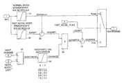
- FIG. 3illustrates the control logic of the subject invention which incorporates the conventional normal mode schedule of FIG. 2 b and an alternate mode schedule for fast engine acceleration;
- FIG. 3 aillustrates the alternate mode schedule overlaid with the normal mode schedule to illustrate the relative differences therein;
- FIG. 4illustrates simulation results of a gas turbine engine rapid acceleration with the normal mode IGV control and with alternate mode IGV control.
- the normal mode schedulereceives an input signal indicative of the corrected compressor speed NL c and outputs a signal indicative of the IGV position commanded from digital engine control (IGVDEMAND).
- IGVDEMANDdigital engine control
- the inlet guide vanesare set at an angle of about 30° until NL c approaches about 66%.
- the inlet guide vane anglesmove to more open settings which reach a maximum open position at an angle of about 100° corresponding to the NL c approaching about 103%.
- the subject inventionoptimizes engine transient response through the use of an alternate IGV control strategy.
- the normal mode IGV scheduleis maintained for high engine power levels to minimize or otherwise optimize fuel burn during normal engine operation, such as during steady-state flight conditions.
- the alternate mode IGV scheduleis designed to maintain high compressor speed while compromising on operating efficiency and engine fuel burn.
- the alternate mode scheduleis considered “more closed” than the normal mode schedule.
- the subject inventionfurther includes transient control logic for use during fast engine accelerations from low engine power.
- the control logicwhich is described in more detail hereinbelow with reference to FIG. 3, is configured to rapidly move the inlet guide vanes from the “more closed” position of the alternate mode schedule to settings which are “more open” than the normal mode schedule. (See FIG. 4 b ) Then, as the engine acceleration nears completion, the control logic smoothly commands the inlet guide vanes back to their normal mode schedule.
- the IGV control strategy or logic of the subject inventionAs configured, the normal mode IGV schedule 10 is selected when the FAST_ACCEL_FLAG is set equal to FALSE. Alternatively, when the FAST_ACCEL_FLAG is set equal to TRUE, the IGV control logic of the subject invention is invoked, and the alternate mode IGV schedule 20 is employed. This results in faster engine accelerations than are provided under the normal mode schedule.
- the alternate IGV schedule 20schedules “more closed” IGV's at low engine speeds than those which are scheduled by the normal mode schedule at low engine speeds, as illustrated in FIG. 3 a .
- the normal mode schedule 10provides that the inlet guide vanes are set at an angle of about 30° until the corrected compressor speed approaches about 66%.
- the alternate mode schedule 20provides that the inlet guide vanes are set at an angle of about 20° until the corrected compressor speed approaches about 73%.
- the output of the alternate IGV schedule 20is the IGV setting IGVSP 1 .
- the difference in IGV setting between the alternate fast acceleration mode schedule (IGVSP 1 ) and the normal mode schedule (IGVSSNOM)is then computed at summing junction 30 to obtain (DIGVSP 1 ).
- An acceleration ratio (NDOTRATIO)is then computed at division block 40 based on the ratio of the acceleration rate demand (NDOT_DEMAND) which defines the numerator of the ratio and the maximum acceleration limit (NDOT_ACCEL_LIMIT) which defines the denominator of the ratio.
- This ratiois then used to compute an IGV anticipator value (DIGVMOD) using a look-up table 50 .
- the anticipatoris zero (0) for low NDOTRATIO's and is greater than one (1.0) when NDOTRATIO nears 1.0.
- the anticipator value DIGVMODis then multiplied with DIGVSP 1 at multiplication block 60 to produce the transient IGV demand DIGVSPTR.
- the demanded transient IGVis then added to the scheduled IGVSP 1 at summing junction 70 to produce the final command signal from the fast acceleration mode IGV logic, which is IGVSPOIL.
- FIG. 4there is illustrated simulation results of a gas turbine engine rapid acceleration with the normal mode IGV control and with the alternate IGV control, with respect to free turbine speed, IGV, high pressure spool speed (NH), and low pressure spool speed (NL).
- IGVfree turbine speed
- NHhigh pressure spool speed
- NLlow pressure spool speed
- the gas turbine engine used for this simulationwas a turboshaft engine with a two-spool gas generator and free turbine driving a helicopter rotor system.
- the low pressure compressorwas equipped with variable inlet guide vanes.
- the acceleration rateswere the same for both traces in FIG. 4 and the improvement in engine power response is due solely to the alternate IGV control strategy.
- control strategy of the subject inventioncan be employed in any gas turbine application equipped with inlet guide vanes where transient engine performance is important.
- the control strategy of the subject inventionmay be employed in gas turbines powering helicopter rotor systems, electrical power generating systems or propeller drive systems.
- the control strategy of the subject inventionwhich results in more rapid power output during gas turbine accelerations, may be applied to gas turbine decelerations. In such an instance, more rapid engine power drops can be achieved.
- the control strategy of the subject inventioncan be employed in any gas turbine application whether single or multiple gas generator spools are employed
Landscapes
- Engineering & Computer Science (AREA)
- Mechanical Engineering (AREA)
- General Engineering & Computer Science (AREA)
- Physics & Mathematics (AREA)
- Geometry (AREA)
- Control Of Positive-Displacement Air Blowers (AREA)
Abstract
Description
Claims (2)
Priority Applications (1)
| Application Number | Priority Date | Filing Date | Title |
|---|---|---|---|
| US10/672,050US6758044B2 (en) | 2001-10-10 | 2003-09-26 | Control system for positioning compressor inlet guide vanes |
Applications Claiming Priority (2)
| Application Number | Priority Date | Filing Date | Title |
|---|---|---|---|
| US09/974,585US6735955B2 (en) | 2001-10-10 | 2001-10-10 | Control system for positioning compressor inlet guide vanes |
| US10/672,050US6758044B2 (en) | 2001-10-10 | 2003-09-26 | Control system for positioning compressor inlet guide vanes |
Related Parent Applications (1)
| Application Number | Title | Priority Date | Filing Date |
|---|---|---|---|
| US09/974,585DivisionUS6735955B2 (en) | 2001-10-10 | 2001-10-10 | Control system for positioning compressor inlet guide vanes |
Publications (2)
| Publication Number | Publication Date |
|---|---|
| US20040055310A1 US20040055310A1 (en) | 2004-03-25 |
| US6758044B2true US6758044B2 (en) | 2004-07-06 |
Family
ID=25522217
Family Applications (2)
| Application Number | Title | Priority Date | Filing Date |
|---|---|---|---|
| US09/974,585Expired - LifetimeUS6735955B2 (en) | 2001-10-10 | 2001-10-10 | Control system for positioning compressor inlet guide vanes |
| US10/672,050Expired - LifetimeUS6758044B2 (en) | 2001-10-10 | 2003-09-26 | Control system for positioning compressor inlet guide vanes |
Family Applications Before (1)
| Application Number | Title | Priority Date | Filing Date |
|---|---|---|---|
| US09/974,585Expired - LifetimeUS6735955B2 (en) | 2001-10-10 | 2001-10-10 | Control system for positioning compressor inlet guide vanes |
Country Status (4)
| Country | Link |
|---|---|
| US (2) | US6735955B2 (en) |
| EP (1) | EP1302669B1 (en) |
| JP (1) | JP2003120325A (en) |
| DE (1) | DE60219741T2 (en) |
Cited By (35)
| Publication number | Priority date | Publication date | Assignee | Title |
|---|---|---|---|---|
| US20040055272A1 (en)* | 2002-09-19 | 2004-03-25 | Mitsubishi Heavy Industries Ltd. | Operation control apparatus and operation control method for single-shaft combined plant |
| US20070013195A1 (en)* | 2005-07-15 | 2007-01-18 | Honeywell International, Inc. | System and method for controlling the frequency output of dual-spool turbogenerators under varying load |
| US20090060707A1 (en)* | 2007-07-25 | 2009-03-05 | Honeywell International, Inc. | Compressor inlet guide vane de-ice control system and method |
| US20100005808A1 (en)* | 2008-07-10 | 2010-01-14 | Hitachi, Ltd. | Twin-shaft gas turbine |
| US20110185698A1 (en)* | 2010-01-29 | 2011-08-04 | Keith Morgan | Free gas turbine with constant temperature-corrected gas generator speed |
| US8452516B1 (en)* | 2012-01-31 | 2013-05-28 | United Technologies Corporation | Variable vane scheduling based on flight conditions for inclement weather |
| US8770912B2 (en) | 2010-04-28 | 2014-07-08 | General Electric Company | Systems, methods, and apparatus for controlling turbine guide vane positions |
| US8850790B2 (en) | 2011-07-22 | 2014-10-07 | Honeywell International Inc. | Gas turbine engine speed control system and method during maximum fuel flow |
| US9068470B2 (en) | 2011-04-21 | 2015-06-30 | General Electric Company | Independently-controlled gas turbine inlet guide vanes and variable stator vanes |
| WO2015116838A1 (en) | 2014-01-31 | 2015-08-06 | AgBiome, Inc. | Modified biological control agents and their uses |
| US9322341B2 (en) | 2013-03-12 | 2016-04-26 | Pratt & Whitney Canada Corp. | System and method for engine transient power response |
| US9528385B2 (en) | 2012-11-23 | 2016-12-27 | Rolls-Royce Plc | Monitoring and control system |
| US9638111B2 (en) | 2011-09-14 | 2017-05-02 | Anthony R. Martinez | Providing oxidation to a gas turbine engine |
| WO2017223501A1 (en) | 2016-06-24 | 2017-12-28 | AgBiome, Inc. | Methods and compositions for spray drying gram-negative bacteria |
| US10060285B2 (en) | 2013-03-13 | 2018-08-28 | United Technologies Corporation | Variable vane control system |
| US10113487B2 (en) | 2013-10-24 | 2018-10-30 | United Technologies Corporation | Cascaded multi-variable control system for a turboshaft engine |
| US10167872B2 (en) | 2010-11-30 | 2019-01-01 | General Electric Company | System and method for operating a compressor |
| WO2019023226A1 (en) | 2017-07-26 | 2019-01-31 | AgBiome, Inc. | Compositions and methods for improving plant health and controlling plant disease and pests |
| WO2019074813A1 (en) | 2017-10-09 | 2019-04-18 | AgBiome, Inc. | Compositions and methods for improving plant health and controlling plant disease and pests |
| WO2019241370A1 (en) | 2018-06-12 | 2019-12-19 | AgBiome, Inc. | Compositions and methods for improving plant health and controlling plant disease |
| WO2020006555A1 (en) | 2018-06-29 | 2020-01-02 | AgBiome, Inc. | Compositions comprising bacteria and methods for controlling plant pests and improving plant health |
| RU2711187C1 (en)* | 2019-04-19 | 2020-01-15 | Публичное акционерное общество "ОДК-Уфимское моторостроительное производственное объединение" (ПАО "ОДК-УМПО") | Position control system of gas turbine compressor guide vanes |
| WO2020077042A1 (en) | 2018-10-10 | 2020-04-16 | AgBiome, Inc. | Compositions and methods for controlling plant pests and improving plant health |
| WO2020092381A1 (en) | 2018-10-30 | 2020-05-07 | AgBiome, Inc. | Bacterial compositions and methods for controlling plant pests and improving plant health |
| US10822104B2 (en) | 2017-08-29 | 2020-11-03 | Pratt & Whitney Canada Corp. | Variable geometries transient control logic |
| WO2020232103A1 (en) | 2019-05-13 | 2020-11-19 | AgBiome, Inc. | Dried biological control agents and their uses |
| WO2020247848A1 (en) | 2019-06-07 | 2020-12-10 | AgBiome, Inc. | Compositions and methods for improving plant health and controlling plant disease |
| US10961921B2 (en) | 2018-09-19 | 2021-03-30 | Pratt & Whitney Canada Corp. | Model-based control system and method for a turboprop engine |
| US11473510B2 (en) | 2019-04-18 | 2022-10-18 | Raytheon Technologies Corporation | Active multi-effector control of high pressure turbine clearances |
| WO2022225926A1 (en) | 2021-04-19 | 2022-10-27 | AgBiome, Inc. | Compositions and methods for improving plant health and controlling plant disease |
| US11486316B2 (en) | 2018-09-13 | 2022-11-01 | Pratt & Whitney Canada Corp. | Method and system for adjusting a variable geometry mechanism |
| WO2022245786A1 (en) | 2021-05-18 | 2022-11-24 | AgBiome, Inc. | Compositions and methods for improving plant health and controlling plant disease |
| WO2023211979A2 (en) | 2022-04-26 | 2023-11-02 | AgBiome, Inc. | Use of bacterial strains to solubilize phosphorus for agriculture |
| WO2024026305A1 (en) | 2022-07-26 | 2024-02-01 | AgBiome, Inc. | Compositions and methods based on pseudomonas chlororaphis for improving plant health and controlling plant disease |
| US12313012B2 (en) | 2023-08-14 | 2025-05-27 | General Electric Company | System and method for reducing a clearance gap in an engine |
Families Citing this family (24)
| Publication number | Priority date | Publication date | Assignee | Title |
|---|---|---|---|---|
| EP1666731A1 (en) | 2004-12-03 | 2006-06-07 | ALSTOM Technology Ltd | Operating method for turbo compressor |
| US7811809B2 (en)* | 2005-06-15 | 2010-10-12 | Saint Louis University | Molecular biosensors for use in competition assays |
| CH699395A1 (en)* | 2008-08-21 | 2010-02-26 | Alstom Technology Ltd | Gas turbine and method of operation. |
| US9021780B2 (en)* | 2008-12-31 | 2015-05-05 | Rolls-Royce Corporation | Energy extraction and transfer system for a gas turbine engine |
| WO2010078497A1 (en)* | 2008-12-31 | 2010-07-08 | Rolls-Royce North American Technologies, Inc. | Variable pressure ratio compressor |
| EP2292910B1 (en)* | 2009-07-21 | 2016-02-10 | Alstom Technology Ltd | Method for the control of gas turbine engines |
| US20110210555A1 (en)* | 2010-02-26 | 2011-09-01 | Xia Jian Y | Gas turbine driven electric power system with constant output through a full range of ambient conditions |
| FR2970508B1 (en)* | 2011-01-13 | 2015-12-11 | Turbomeca | COMPRESSION ASSEMBLY AND TURBOMOTOR EQUIPPED WITH SUCH ASSEMBLY |
| FR2976622B1 (en)* | 2011-06-16 | 2015-05-01 | Turbomeca | DOUBLE TURBOMOTEUR BODY ARCHITECTURE WITH HIGH PRESSURE COMPRESSOR CONNECTED TO LOW PRESSURE TURBINE |
| US9279388B2 (en)* | 2011-11-01 | 2016-03-08 | United Technologies Corporation | Gas turbine engine with two-spool fan and variable vane turbine |
| US20140053567A1 (en)* | 2012-08-22 | 2014-02-27 | Fritz Langenbacher | System and method for controlling a gas turbine engine generator set |
| US10267326B2 (en)* | 2012-09-27 | 2019-04-23 | United Technologies Corporation | Variable vane scheduling |
| JP6366259B2 (en)* | 2013-11-18 | 2018-08-01 | 三菱日立パワーシステムズ株式会社 | Control device and control method for two-shaft gas turbine |
| EP2907990A1 (en)* | 2014-02-18 | 2015-08-19 | Siemens Aktiengesellschaft | Method for operating a gas turbine installation, and the same |
| US9695752B2 (en)* | 2014-09-05 | 2017-07-04 | Honeywell International Inc. | Engine-induced aircraft cabin resonance reduction system and method |
| US11015531B2 (en)* | 2014-09-05 | 2021-05-25 | Honeywell International Inc. | Engine-induced aircraft cabin resonance reduction system and method |
| JP6364363B2 (en)* | 2015-02-23 | 2018-07-25 | 三菱日立パワーシステムズ株式会社 | Two-shaft gas turbine and control device and control method thereof |
| EP3225812B1 (en)* | 2016-03-29 | 2019-02-27 | Mitsubishi Hitachi Power Systems, Ltd. | A two-shaft gas turbine, and the control method of opening degree of inlet guide vane of the gas turbine |
| GB201803137D0 (en)* | 2018-02-27 | 2018-04-11 | Rolls Royce Plc | Gas turbine engine compressor management system |
| CA3051562A1 (en)* | 2018-08-08 | 2020-02-08 | Pratt & Whitney Canada Corp. | Multi-engine system and method |
| US11554874B2 (en)* | 2020-10-02 | 2023-01-17 | Pratt & Whitney Canada Corp. | Method and system for governing an engine at low power |
| CN113294246B (en)* | 2021-06-30 | 2022-11-04 | 中国航发动力股份有限公司 | Method for controlling rotatable guide vanes of gas turbine |
| CN114060102B (en)* | 2021-11-10 | 2022-11-04 | 北京航空航天大学 | Method and device for determining outlet metal angle of guide vane blade |
| US12410758B2 (en)* | 2022-01-10 | 2025-09-09 | General Electric Company | Three-stream gas turbine engine control |
Citations (4)
| Publication number | Priority date | Publication date | Assignee | Title |
|---|---|---|---|---|
| US4184327A (en)* | 1977-12-09 | 1980-01-22 | The United States Of America As Represented By The Administrator Of The National Aeronautics And Space Administration | Method and apparatus for rapid thrust increases in a turbofan engine |
| GB2119862A (en)* | 1982-05-06 | 1983-11-23 | Gen Electric | Variable stator vane (VSV) closed loop control system of a compressor |
| US4928482A (en)* | 1988-09-20 | 1990-05-29 | United Technologies Corporation | Control of high compressor vanes and fuel for a gas turbine engine |
| US5259188A (en)* | 1992-08-24 | 1993-11-09 | General Electric Company | Method and system to increase stall margin |
Family Cites Families (3)
| Publication number | Priority date | Publication date | Assignee | Title |
|---|---|---|---|---|
| GB1313841A (en) | 1967-01-18 | 1973-04-18 | Secr Defence | Gas turbine jet propulsion engine |
| GB2016597B (en) | 1978-03-14 | 1982-11-17 | Rolls Royce | Controlling guide vane angle of an axial-flow compressor of a gas turbine engine |
| WO1990010148A1 (en) | 1989-02-27 | 1990-09-07 | United Technologies Corporation | Method and system for controlling variable compressor geometry |
- 2001
- 2001-10-10USUS09/974,585patent/US6735955B2/ennot_activeExpired - Lifetime
- 2002
- 2002-09-17DEDE60219741Tpatent/DE60219741T2/ennot_activeExpired - Lifetime
- 2002-09-17EPEP02020828Apatent/EP1302669B1/ennot_activeExpired - Lifetime
- 2002-10-08JPJP2002295129Apatent/JP2003120325A/enactivePending
- 2003
- 2003-09-26USUS10/672,050patent/US6758044B2/ennot_activeExpired - Lifetime
Patent Citations (4)
| Publication number | Priority date | Publication date | Assignee | Title |
|---|---|---|---|---|
| US4184327A (en)* | 1977-12-09 | 1980-01-22 | The United States Of America As Represented By The Administrator Of The National Aeronautics And Space Administration | Method and apparatus for rapid thrust increases in a turbofan engine |
| GB2119862A (en)* | 1982-05-06 | 1983-11-23 | Gen Electric | Variable stator vane (VSV) closed loop control system of a compressor |
| US4928482A (en)* | 1988-09-20 | 1990-05-29 | United Technologies Corporation | Control of high compressor vanes and fuel for a gas turbine engine |
| US5259188A (en)* | 1992-08-24 | 1993-11-09 | General Electric Company | Method and system to increase stall margin |
Cited By (45)
| Publication number | Priority date | Publication date | Assignee | Title |
|---|---|---|---|---|
| US6817186B2 (en)* | 2002-09-19 | 2004-11-16 | Mitsubishi Heavy Industries, Ltd. | Operation control apparatus and operation control method for single-shaft combined plant |
| US20040055272A1 (en)* | 2002-09-19 | 2004-03-25 | Mitsubishi Heavy Industries Ltd. | Operation control apparatus and operation control method for single-shaft combined plant |
| US20070013195A1 (en)* | 2005-07-15 | 2007-01-18 | Honeywell International, Inc. | System and method for controlling the frequency output of dual-spool turbogenerators under varying load |
| US7245040B2 (en) | 2005-07-15 | 2007-07-17 | Honeywell International, Inc. | System and method for controlling the frequency output of dual-spool turbogenerators under varying load |
| US7762081B2 (en) | 2007-07-25 | 2010-07-27 | Honeywell International Inc. | Compressor inlet guide vane de-ice control system and method |
| US20090060707A1 (en)* | 2007-07-25 | 2009-03-05 | Honeywell International, Inc. | Compressor inlet guide vane de-ice control system and method |
| US8272223B2 (en)* | 2008-07-10 | 2012-09-25 | Hitachi, Ltd. | Twin-shaft gas turbine including a control system for adjusting the compressor inlet guide vane angle to optimize engine transient response |
| US8196414B2 (en)* | 2008-07-10 | 2012-06-12 | Hitachi, Ltd. | Twin-shaft gas turbine including a control system for adjusting the compressor inlet guide vane angle to optimize engine transient response |
| US20100005808A1 (en)* | 2008-07-10 | 2010-01-14 | Hitachi, Ltd. | Twin-shaft gas turbine |
| US20110126547A1 (en)* | 2008-07-10 | 2011-06-02 | Hitachi, Ltd. | Twin-shaft gas turbine |
| US20110185698A1 (en)* | 2010-01-29 | 2011-08-04 | Keith Morgan | Free gas turbine with constant temperature-corrected gas generator speed |
| US9512784B2 (en)* | 2010-01-29 | 2016-12-06 | Pratt & Whitney Canada Corp. | Free gas turbine with constant temperature-corrected gas generator speed |
| US8770912B2 (en) | 2010-04-28 | 2014-07-08 | General Electric Company | Systems, methods, and apparatus for controlling turbine guide vane positions |
| US10167872B2 (en) | 2010-11-30 | 2019-01-01 | General Electric Company | System and method for operating a compressor |
| US9068470B2 (en) | 2011-04-21 | 2015-06-30 | General Electric Company | Independently-controlled gas turbine inlet guide vanes and variable stator vanes |
| US8850790B2 (en) | 2011-07-22 | 2014-10-07 | Honeywell International Inc. | Gas turbine engine speed control system and method during maximum fuel flow |
| US9638111B2 (en) | 2011-09-14 | 2017-05-02 | Anthony R. Martinez | Providing oxidation to a gas turbine engine |
| US8452516B1 (en)* | 2012-01-31 | 2013-05-28 | United Technologies Corporation | Variable vane scheduling based on flight conditions for inclement weather |
| US9528385B2 (en) | 2012-11-23 | 2016-12-27 | Rolls-Royce Plc | Monitoring and control system |
| US9322341B2 (en) | 2013-03-12 | 2016-04-26 | Pratt & Whitney Canada Corp. | System and method for engine transient power response |
| US10060285B2 (en) | 2013-03-13 | 2018-08-28 | United Technologies Corporation | Variable vane control system |
| US10113487B2 (en) | 2013-10-24 | 2018-10-30 | United Technologies Corporation | Cascaded multi-variable control system for a turboshaft engine |
| WO2015116838A1 (en) | 2014-01-31 | 2015-08-06 | AgBiome, Inc. | Modified biological control agents and their uses |
| EP3977859A1 (en) | 2014-01-31 | 2022-04-06 | Agbiome, Inc. | Modified biological control agents and their uses |
| EP4268594A2 (en) | 2016-06-24 | 2023-11-01 | Agbiome, Inc. | Methods and compositions for spray drying gram-negative bacteria |
| WO2017223501A1 (en) | 2016-06-24 | 2017-12-28 | AgBiome, Inc. | Methods and compositions for spray drying gram-negative bacteria |
| WO2019023226A1 (en) | 2017-07-26 | 2019-01-31 | AgBiome, Inc. | Compositions and methods for improving plant health and controlling plant disease and pests |
| US10822104B2 (en) | 2017-08-29 | 2020-11-03 | Pratt & Whitney Canada Corp. | Variable geometries transient control logic |
| WO2019074813A1 (en) | 2017-10-09 | 2019-04-18 | AgBiome, Inc. | Compositions and methods for improving plant health and controlling plant disease and pests |
| WO2019241370A1 (en) | 2018-06-12 | 2019-12-19 | AgBiome, Inc. | Compositions and methods for improving plant health and controlling plant disease |
| WO2020006555A1 (en) | 2018-06-29 | 2020-01-02 | AgBiome, Inc. | Compositions comprising bacteria and methods for controlling plant pests and improving plant health |
| US11486316B2 (en) | 2018-09-13 | 2022-11-01 | Pratt & Whitney Canada Corp. | Method and system for adjusting a variable geometry mechanism |
| US10961921B2 (en) | 2018-09-19 | 2021-03-30 | Pratt & Whitney Canada Corp. | Model-based control system and method for a turboprop engine |
| WO2020077042A1 (en) | 2018-10-10 | 2020-04-16 | AgBiome, Inc. | Compositions and methods for controlling plant pests and improving plant health |
| WO2020092381A1 (en) | 2018-10-30 | 2020-05-07 | AgBiome, Inc. | Bacterial compositions and methods for controlling plant pests and improving plant health |
| US11473510B2 (en) | 2019-04-18 | 2022-10-18 | Raytheon Technologies Corporation | Active multi-effector control of high pressure turbine clearances |
| RU2711187C1 (en)* | 2019-04-19 | 2020-01-15 | Публичное акционерное общество "ОДК-Уфимское моторостроительное производственное объединение" (ПАО "ОДК-УМПО") | Position control system of gas turbine compressor guide vanes |
| WO2020232103A1 (en) | 2019-05-13 | 2020-11-19 | AgBiome, Inc. | Dried biological control agents and their uses |
| WO2020247848A1 (en) | 2019-06-07 | 2020-12-10 | AgBiome, Inc. | Compositions and methods for improving plant health and controlling plant disease |
| WO2022225925A1 (en) | 2021-04-19 | 2022-10-27 | AgBiome, Inc. | Compositions and methods for improving plant health and controlling plant disease |
| WO2022225926A1 (en) | 2021-04-19 | 2022-10-27 | AgBiome, Inc. | Compositions and methods for improving plant health and controlling plant disease |
| WO2022245786A1 (en) | 2021-05-18 | 2022-11-24 | AgBiome, Inc. | Compositions and methods for improving plant health and controlling plant disease |
| WO2023211979A2 (en) | 2022-04-26 | 2023-11-02 | AgBiome, Inc. | Use of bacterial strains to solubilize phosphorus for agriculture |
| WO2024026305A1 (en) | 2022-07-26 | 2024-02-01 | AgBiome, Inc. | Compositions and methods based on pseudomonas chlororaphis for improving plant health and controlling plant disease |
| US12313012B2 (en) | 2023-08-14 | 2025-05-27 | General Electric Company | System and method for reducing a clearance gap in an engine |
Also Published As
| Publication number | Publication date |
|---|---|
| US20040055310A1 (en) | 2004-03-25 |
| EP1302669B1 (en) | 2007-04-25 |
| DE60219741T2 (en) | 2007-08-16 |
| EP1302669A2 (en) | 2003-04-16 |
| JP2003120325A (en) | 2003-04-23 |
| EP1302669A3 (en) | 2003-11-19 |
| US6735955B2 (en) | 2004-05-18 |
| DE60219741D1 (en) | 2007-06-06 |
| US20030066294A1 (en) | 2003-04-10 |
Similar Documents
| Publication | Publication Date | Title |
|---|---|---|
| US6758044B2 (en) | Control system for positioning compressor inlet guide vanes | |
| US11286865B2 (en) | Gas turbine engine with variable pitch fan and variable pitch compressor geometry | |
| US5133182A (en) | Control of low compressor vanes and fuel for a gas turbine engine | |
| US10378454B2 (en) | Gas turbine engine with two-spool fan and variable vane turbine | |
| EP0412127B1 (en) | Method and system for controlling variable compressor geometry | |
| US10040565B2 (en) | Single lever turboprop control systems and methods utilizing torque-based and power based scheduling | |
| US4242864A (en) | Integrated control system for a gas turbine engine | |
| US4928482A (en) | Control of high compressor vanes and fuel for a gas turbine engine | |
| EP0005135B1 (en) | Exhaust nozzle control and core engine fuel control for turbofan engine | |
| US9567906B2 (en) | Systems and methods for controlling aircraft main engine speeds by adjusting compressed air flow from an APU | |
| US4423592A (en) | Fuel control system for gas turbine engine | |
| EP0092425B1 (en) | Gas turbine engine fuel control | |
| US20130104522A1 (en) | Gas turbine engine with variable pitch first stage fan section | |
| EP0363301B1 (en) | Control system for gas turbine engines | |
| EP0733159B1 (en) | Closed loop stator vane control | |
| US11746713B2 (en) | Fuel control system | |
| EP3315743B1 (en) | Power plant thrust management system for turboprop engines | |
| US4947643A (en) | Active geometry control system for gas turbine engines | |
| US4102595A (en) | Bleed valve control system | |
| US12170500B2 (en) | Active stability control of compression systems utilizing electric machines | |
| US10859003B2 (en) | Control system for a gas turbine engine | |
| EP4336035A1 (en) | High bandwidth control of turbofan/turboprop thrust response using embedded electric machines | |
| CN109681331B (en) | Method for calculating FMV expected value increment of fuel metering valve | |
| Maruyama et al. | Research of Engine Optimal Control | |
| IL91682A (en) | Control system for gas turbine engines |
Legal Events
| Date | Code | Title | Description |
|---|---|---|---|
| STCF | Information on status: patent grant | Free format text:PATENTED CASE | |
| FPAY | Fee payment | Year of fee payment:4 | |
| REMI | Maintenance fee reminder mailed | ||
| FPAY | Fee payment | Year of fee payment:8 | |
| AS | Assignment | Owner name:TRIUMPH ENGINE CONTROL SYSTEMS, LLC, CONNECTICUT Free format text:ASSIGNMENT OF ASSIGNORS INTEREST;ASSIGNOR:GOODRICH PUMP AND ENGINE CONTROL SYSTEMS, INC.;REEL/FRAME:030909/0876 Effective date:20130625 | |
| AS | Assignment | Owner name:PNC BANK, NATIONAL ASSOCIATION, PENNSYLVANIA Free format text:ACKNOWLEDGEMENT OF SECURITY INTEREST IN IP;ASSIGNORS:TRIUMPH GROUP, INC.;TRIUMPH INSULATION SYSTEMS, LLC;TRIUMPH ACTUATION SYSTEMS, LLC;AND OTHERS;REEL/FRAME:031690/0794 Effective date:20131119 | |
| FPAY | Fee payment | Year of fee payment:12 | |
| AS | Assignment | Owner name:U.S. BANK NATIONAL ASSOCIATION, AS COLLATERAL AGEN Free format text:GRANT OF SECURITY INTEREST IN PATENT RIGHTS;ASSIGNORS:TRIUMPH ACTUATION SYSTEMS - CONNECTICUT, LLC;TRIUMPH AEROSTRUCTURES, LLC;TRIUMPH CONTROLS, LLC;AND OTHERS;REEL/FRAME:050624/0641 Effective date:20190923 | |
| AS | Assignment | Owner name:TRIUMPH INTEGRATED AIRCRAFT INTERIORS, INC., PENNSYLVANIA Free format text:RELEASE BY SECURED PARTY;ASSIGNOR:PNC BANK, NATIONAL ASSOCIATION;REEL/FRAME:053516/0200 Effective date:20200817 Owner name:TRIUMPH AEROSTRUCTURES, LLC, TEXAS Free format text:RELEASE BY SECURED PARTY;ASSIGNOR:PNC BANK, NATIONAL ASSOCIATION;REEL/FRAME:053516/0200 Effective date:20200817 Owner name:TRIUMPH INSULATION SYSTEMS, LLC, CALIFORNIA Free format text:RELEASE BY SECURED PARTY;ASSIGNOR:PNC BANK, NATIONAL ASSOCIATION;REEL/FRAME:053516/0200 Effective date:20200817 Owner name:TRIUMPH ACTUATION SYSTEMS, LLC, PENNSYLVANIA Free format text:RELEASE BY SECURED PARTY;ASSIGNOR:PNC BANK, NATIONAL ASSOCIATION;REEL/FRAME:053516/0200 Effective date:20200817 Owner name:TRIUMPH THERMAL SYSTEMS - MARYLAND, INC., PENNSYLVANIA Free format text:RELEASE BY SECURED PARTY;ASSIGNOR:PNC BANK, NATIONAL ASSOCIATION;REEL/FRAME:053516/0200 Effective date:20200817 Owner name:TRIUMPH BRANDS, INC., PENNSYLVANIA Free format text:RELEASE BY SECURED PARTY;ASSIGNOR:PNC BANK, NATIONAL ASSOCIATION;REEL/FRAME:053516/0200 Effective date:20200817 Owner name:TRIUMPH CONTROLS, LLC, PENNSYLVANIA Free format text:RELEASE BY SECURED PARTY;ASSIGNOR:PNC BANK, NATIONAL ASSOCIATION;REEL/FRAME:053516/0200 Effective date:20200817 Owner name:TRIUMPH ACTUATION SYSTEMS - CONNECTICUT, LLC, PENNSYLVANIA Free format text:RELEASE BY SECURED PARTY;ASSIGNOR:PNC BANK, NATIONAL ASSOCIATION;REEL/FRAME:053516/0200 Effective date:20200817 Owner name:TRIUMPH GROUP, INC., PENNSYLVANIA Free format text:RELEASE BY SECURED PARTY;ASSIGNOR:PNC BANK, NATIONAL ASSOCIATION;REEL/FRAME:053516/0200 Effective date:20200817 Owner name:TRIUMPH ENGINE CONTROL SYSTEMS, LLC, PENNSYLVANIA Free format text:RELEASE BY SECURED PARTY;ASSIGNOR:PNC BANK, NATIONAL ASSOCIATION;REEL/FRAME:053516/0200 Effective date:20200817 Owner name:TRIUMPH GEAR SYSTEMS, INC., UTAH Free format text:RELEASE BY SECURED PARTY;ASSIGNOR:PNC BANK, NATIONAL ASSOCIATION;REEL/FRAME:053516/0200 Effective date:20200817 Owner name:TRIUMPH ENGINEERED SOLUTIONS, INC., ARIZONA Free format text:RELEASE BY SECURED PARTY;ASSIGNOR:PNC BANK, NATIONAL ASSOCIATION;REEL/FRAME:053516/0200 Effective date:20200817 Owner name:TRIUMPH ACTUATION SYSTEMS - YAKIMA, LLC, WASHINGTON Free format text:RELEASE BY SECURED PARTY;ASSIGNOR:PNC BANK, NATIONAL ASSOCIATION;REEL/FRAME:053516/0200 Effective date:20200817 | |
| AS | Assignment | Owner name:WILMINGTON TRUST, NATIONAL ASSOCIATION, MINNESOTA Free format text:GRANT OF SECURITY INTEREST IN PATENT RIGHTS;ASSIGNORS:TRIUMPH ACTUATION SYSTEMS - CONNECTICUT, LLC;TRIUMPH AEROSTRUCTURES, LLC;TRIUMPH CONTROLS, LLC;AND OTHERS;REEL/FRAME:053570/0149 Effective date:20200820 | |
| AS | Assignment | Owner name:TRIUMPH ENGINE CONTROL SYSTEMS, LLC, PENNSYLVANIA Free format text:RELEASE BY SECURED PARTY;ASSIGNOR:U.S. BANK TRUST COMPANY, NATIONAL ASSOCIATION;REEL/FRAME:064050/0497 Effective date:20230314 Owner name:TRIUMPH AEROSTRUCTURES, LLC., TEXAS Free format text:RELEASE BY SECURED PARTY;ASSIGNOR:U.S. BANK TRUST COMPANY, NATIONAL ASSOCIATION;REEL/FRAME:064050/0497 Effective date:20230314 Owner name:TRIUMPH AEROSTRUCTURES, LLC, TEXAS Free format text:RELEASE BY SECURED PARTY;ASSIGNOR:U.S. BANK TRUST COMPANY, NATIONAL ASSOCIATION;REEL/FRAME:064050/0497 Effective date:20230314 Owner name:TRIUMPH ACTUATION SYSTEMS - CONNECTICUT, LLC, PENNSYLVANIA Free format text:RELEASE BY SECURED PARTY;ASSIGNOR:U.S. BANK TRUST COMPANY, NATIONAL ASSOCIATION;REEL/FRAME:064050/0497 Effective date:20230314 Owner name:TRIUMPH THERMAL SYSTEMS - MARYLAND, INC., PENNSYLVANIA Free format text:RELEASE BY SECURED PARTY;ASSIGNOR:U.S. BANK TRUST COMPANY, NATIONAL ASSOCIATION;REEL/FRAME:064050/0497 Effective date:20230314 Owner name:TRIUMPH CONTROLS, LLC, PENNSYLVANIA Free format text:RELEASE BY SECURED PARTY;ASSIGNOR:U.S. BANK TRUST COMPANY, NATIONAL ASSOCIATION;REEL/FRAME:064050/0497 Effective date:20230314 Owner name:TRIUMPH GROUP, INC., PENNSYLVANIA Free format text:RELEASE BY SECURED PARTY;ASSIGNOR:U.S. BANK TRUST COMPANY, NATIONAL ASSOCIATION;REEL/FRAME:064050/0497 Effective date:20230314 | |
| AS | Assignment | Owner name:TRIUMPH ACTUATION SYSTEMS-CONNECTICUT, LLC, PENNSYLVANIA Free format text:RELEASE OF SECURITY INTEREST RECORDED AT REEL/FRAME 053570/0149;ASSIGNOR:WILMINGTON TRUST, NATIONAL ASSOCIATION;REEL/FRAME:072224/0841 Effective date:20250724 Owner name:TRIUMPH AEROSTRUCTURES, LLC, TEXAS Free format text:RELEASE OF SECURITY INTEREST RECORDED AT REEL/FRAME 053570/0149;ASSIGNOR:WILMINGTON TRUST, NATIONAL ASSOCIATION;REEL/FRAME:072224/0841 Effective date:20250724 Owner name:TRIUMPH CONTROLS, LLC, PENNSYLVANIA Free format text:RELEASE OF SECURITY INTEREST RECORDED AT REEL/FRAME 053570/0149;ASSIGNOR:WILMINGTON TRUST, NATIONAL ASSOCIATION;REEL/FRAME:072224/0841 Effective date:20250724 Owner name:TRIUMPH ENGINE CONTROL SYSTEMS, LLC, PENNSYLVANIA Free format text:RELEASE OF SECURITY INTEREST RECORDED AT REEL/FRAME 053570/0149;ASSIGNOR:WILMINGTON TRUST, NATIONAL ASSOCIATION;REEL/FRAME:072224/0841 Effective date:20250724 Owner name:TRIUMPH THERMAL SYSTEMS-MARYLAND, INC., PENNSYLVANIA Free format text:RELEASE OF SECURITY INTEREST RECORDED AT REEL/FRAME 053570/0149;ASSIGNOR:WILMINGTON TRUST, NATIONAL ASSOCIATION;REEL/FRAME:072224/0841 Effective date:20250724 Owner name:TRIUMPH INTEGRATED AIRCRAFT INTERIORS, INC., PENNSYLVANIA Free format text:RELEASE OF SECURITY INTEREST RECORDED AT REEL/FRAME 053570/0149;ASSIGNOR:WILMINGTON TRUST, NATIONAL ASSOCIATION;REEL/FRAME:072224/0841 Effective date:20250724 |