US6756975B1 - Matrix type display apparatus, method of production thereof, and thermo-compression bonding head - Google Patents
Matrix type display apparatus, method of production thereof, and thermo-compression bonding headDownload PDFInfo
- Publication number
- US6756975B1 US6756975B1US09/280,955US28095599AUS6756975B1US 6756975 B1US6756975 B1US 6756975B1US 28095599 AUS28095599 AUS 28095599AUS 6756975 B1US6756975 B1US 6756975B1
- Authority
- US
- United States
- Prior art keywords
- driving ics
- data bus
- display apparatus
- driving
- area
- Prior art date
- Legal status (The legal status is an assumption and is not a legal conclusion. Google has not performed a legal analysis and makes no representation as to the accuracy of the status listed.)
- Expired - Lifetime, expires
Links
Images


Classifications
- H—ELECTRICITY
- H01—ELECTRIC ELEMENTS
- H01L—SEMICONDUCTOR DEVICES NOT COVERED BY CLASS H10
- H01L23/00—Details of semiconductor or other solid state devices
- H01L23/48—Arrangements for conducting electric current to or from the solid state body in operation, e.g. leads, terminal arrangements ; Selection of materials therefor
- H01L23/488—Arrangements for conducting electric current to or from the solid state body in operation, e.g. leads, terminal arrangements ; Selection of materials therefor consisting of soldered or bonded constructions
- H01L23/498—Leads, i.e. metallisations or lead-frames on insulating substrates, e.g. chip carriers
- H01L23/49838—Geometry or layout
- G—PHYSICS
- G02—OPTICS
- G02F—OPTICAL DEVICES OR ARRANGEMENTS FOR THE CONTROL OF LIGHT BY MODIFICATION OF THE OPTICAL PROPERTIES OF THE MEDIA OF THE ELEMENTS INVOLVED THEREIN; NON-LINEAR OPTICS; FREQUENCY-CHANGING OF LIGHT; OPTICAL LOGIC ELEMENTS; OPTICAL ANALOGUE/DIGITAL CONVERTERS
- G02F1/00—Devices or arrangements for the control of the intensity, colour, phase, polarisation or direction of light arriving from an independent light source, e.g. switching, gating or modulating; Non-linear optics
- G02F1/01—Devices or arrangements for the control of the intensity, colour, phase, polarisation or direction of light arriving from an independent light source, e.g. switching, gating or modulating; Non-linear optics for the control of the intensity, phase, polarisation or colour
- G02F1/13—Devices or arrangements for the control of the intensity, colour, phase, polarisation or direction of light arriving from an independent light source, e.g. switching, gating or modulating; Non-linear optics for the control of the intensity, phase, polarisation or colour based on liquid crystals, e.g. single liquid crystal display cells
- G02F1/133—Constructional arrangements; Operation of liquid crystal cells; Circuit arrangements
- G02F1/1333—Constructional arrangements; Manufacturing methods
- G02F1/1345—Conductors connecting electrodes to cell terminals
- G02F1/13452—Conductors connecting driver circuitry and terminals of panels
- H—ELECTRICITY
- H01—ELECTRIC ELEMENTS
- H01L—SEMICONDUCTOR DEVICES NOT COVERED BY CLASS H10
- H01L24/00—Arrangements for connecting or disconnecting semiconductor or solid-state bodies; Methods or apparatus related thereto
- H01L24/80—Methods for connecting semiconductor or other solid state bodies using means for bonding being attached to, or being formed on, the surface to be connected
- H—ELECTRICITY
- H01—ELECTRIC ELEMENTS
- H01L—SEMICONDUCTOR DEVICES NOT COVERED BY CLASS H10
- H01L2224/00—Indexing scheme for arrangements for connecting or disconnecting semiconductor or solid-state bodies and methods related thereto as covered by H01L24/00
- H01L2224/80—Methods for connecting semiconductor or other solid state bodies using means for bonding being attached to, or being formed on, the surface to be connected
- H01L2224/83—Methods for connecting semiconductor or other solid state bodies using means for bonding being attached to, or being formed on, the surface to be connected using a layer connector
- H01L2224/838—Bonding techniques
- H01L2224/8385—Bonding techniques using a polymer adhesive, e.g. an adhesive based on silicone, epoxy, polyimide, polyester
- H01L2224/83851—Bonding techniques using a polymer adhesive, e.g. an adhesive based on silicone, epoxy, polyimide, polyester being an anisotropic conductive adhesive
- H—ELECTRICITY
- H01—ELECTRIC ELEMENTS
- H01L—SEMICONDUCTOR DEVICES NOT COVERED BY CLASS H10
- H01L2924/00—Indexing scheme for arrangements or methods for connecting or disconnecting semiconductor or solid-state bodies as covered by H01L24/00
- H01L2924/01—Chemical elements
- H01L2924/01004—Beryllium [Be]
- H—ELECTRICITY
- H01—ELECTRIC ELEMENTS
- H01L—SEMICONDUCTOR DEVICES NOT COVERED BY CLASS H10
- H01L2924/00—Indexing scheme for arrangements or methods for connecting or disconnecting semiconductor or solid-state bodies as covered by H01L24/00
- H01L2924/01—Chemical elements
- H01L2924/01005—Boron [B]
- H—ELECTRICITY
- H01—ELECTRIC ELEMENTS
- H01L—SEMICONDUCTOR DEVICES NOT COVERED BY CLASS H10
- H01L2924/00—Indexing scheme for arrangements or methods for connecting or disconnecting semiconductor or solid-state bodies as covered by H01L24/00
- H01L2924/01—Chemical elements
- H01L2924/01006—Carbon [C]
- H—ELECTRICITY
- H01—ELECTRIC ELEMENTS
- H01L—SEMICONDUCTOR DEVICES NOT COVERED BY CLASS H10
- H01L2924/00—Indexing scheme for arrangements or methods for connecting or disconnecting semiconductor or solid-state bodies as covered by H01L24/00
- H01L2924/01—Chemical elements
- H01L2924/01033—Arsenic [As]
- H—ELECTRICITY
- H01—ELECTRIC ELEMENTS
- H01L—SEMICONDUCTOR DEVICES NOT COVERED BY CLASS H10
- H01L2924/00—Indexing scheme for arrangements or methods for connecting or disconnecting semiconductor or solid-state bodies as covered by H01L24/00
- H01L2924/01—Chemical elements
- H01L2924/01082—Lead [Pb]
- H—ELECTRICITY
- H01—ELECTRIC ELEMENTS
- H01L—SEMICONDUCTOR DEVICES NOT COVERED BY CLASS H10
- H01L2924/00—Indexing scheme for arrangements or methods for connecting or disconnecting semiconductor or solid-state bodies as covered by H01L24/00
- H01L2924/10—Details of semiconductor or other solid state devices to be connected
- H01L2924/11—Device type
- H01L2924/14—Integrated circuits
- H—ELECTRICITY
- H05—ELECTRIC TECHNIQUES NOT OTHERWISE PROVIDED FOR
- H05K—PRINTED CIRCUITS; CASINGS OR CONSTRUCTIONAL DETAILS OF ELECTRIC APPARATUS; MANUFACTURE OF ASSEMBLAGES OF ELECTRICAL COMPONENTS
- H05K1/00—Printed circuits
- H05K1/02—Details
- H05K1/11—Printed elements for providing electric connections to or between printed circuits
- H05K1/118—Printed elements for providing electric connections to or between printed circuits specially for flexible printed circuits, e.g. using folded portions
- H—ELECTRICITY
- H05—ELECTRIC TECHNIQUES NOT OTHERWISE PROVIDED FOR
- H05K—PRINTED CIRCUITS; CASINGS OR CONSTRUCTIONAL DETAILS OF ELECTRIC APPARATUS; MANUFACTURE OF ASSEMBLAGES OF ELECTRICAL COMPONENTS
- H05K3/00—Apparatus or processes for manufacturing printed circuits
- H05K3/36—Assembling printed circuits with other printed circuits
- H05K3/361—Assembling flexible printed circuits with other printed circuits
Definitions
- the present inventionrelates to a matrix type display apparatus such as a liquid crystal display apparatus of a COG (chip-on-glass) system carrying driving ICs on a liquid crystal panel or a plasma display apparatus, a method for production thereof and a thermo-compression bonding head used for production of the matrix type display apparatus.
- a matrix type display apparatussuch as a liquid crystal display apparatus of a COG (chip-on-glass) system carrying driving ICs on a liquid crystal panel or a plasma display apparatus, a method for production thereof and a thermo-compression bonding head used for production of the matrix type display apparatus.
- FIG. 19 of the attached drawingsis a schematic front view illustrating part of one conventional liquid crystal display apparatus of a COG system.
- reference numeral 1denotes a liquid crystal panel
- 2denotes a common substrate on which a common electrode is formed
- 3denotes a TFT substrate on which pixel electrodes, data buses, gate buses; and TFTs (thin film transistors) are formed
- 4denotes a display area for displaying images.
- Reference numeral 5denotes an area for mounting ICs for driving data buses provided on the TFT substrate 5 ; 6 to 10 denote ICs mounted thereon for driving the data buses; 11 denotes a group of connection terminals for connection to a flexible circuit board; and 12 denotes the flexible circuit board.
- Reference numeral 13denotes an area provided in the TFT substrate 3 for mounting ICs for driving the gate buses; and 14 denotes an IC mounted therein for driving the gate buses.
- the data buses, gate buses or othersare not shown in the drawing.
- a flexible circuit board 12is used for supplying a power source voltage for the data bus-driving ICs 6 to 10 and/or the gate bus-driving IC 14 , or delivering signals necessary therefor, and is connected via an anisotropic conductive film by a thermo-contact bonding.
- FIG. 20is a schematic front view illustrating part of another conventional liquid crystal display apparatus of a COG system.
- reference numeral 16denotes a liquid crystal panel; 17 a common substrate on which a common electrode is formed; and 18 denotes a TFT substrate on which pixel electrodes are formed; and 18 denotes a TFT substrate on which pixel electrodes, data buses, and TFTs are formed.
- Reference numeral 19denotes an area in which an IC for driving the data buses is mounted; 20 denotes the IC mounted therein for driving the data buses; 21 denotes the data buses; 22 - 1 to 22 - 4 and 23 - 1 to 23 - 4 denote connection terminals for connection to a flexible circuit board (not shown).
- a liquid crystal display apparatusIn a portable type information apparatus such as a notebook type or a mobile personal computer, it is required that a liquid crystal display apparatus has a narrower picture frame around the display area for the purpose of further miniaturization of the apparatus.
- the conventional liquid crystal display apparatus shown in FIG. 20has the connection terminals 22 - 1 to 22 - 4 and 23 - 1 to 23 - 4 on the opposite shorter sides, respectively, of the data bus-driving IC 20 .
- the connection terminals 22 - 1 to 22 - 4 and 23 - 1 to 23 - 4are arranged in the width wise direction in the area 19 for mounting the data bus-driving IC, it is impossible to reduce the width of the area 19 for mounting the data bus-driving IC, and therefore, to realize a narrow-framed liquid crystal display apparatus.
- leads for connecting the connection terminals 22 - 2 to 22 - 4 and 23 - 2 to 23 - 4 with the data bus-driving IC 20extend from the longer side of the data bus-driving IC 20 in the conventional liquid crystal display apparatus shown in FIG. 20, it is impossible, in this regard, to reduce the width of the area 19 for mounting the data bus-driving IC, and therefore, to realize a narrow-framed liquid crystal display apparatus.
- an object of the present inventionis to provide a matrix type display apparatus by which a narrow-framed structure is achievable, a method for production thereof and a thermo-contact bonding head suitably used for production of such a matrix type display apparatus.
- a matrix type display apparatuscomprises a first substrate, a second substrate disposed opposite to the first substrate and having an area for mounting a plurality of driving ICs in substantially one row along an alignment direction so that longer sides of the ICs are aligned with the arrangement direction, and connection terminals for connection with a third substrate, said connection terminals being arranged in the area for mounting the driving ICs at positions on the shorter sides of the respective driving ICs along the arrangement direction of the plurality of driving ICs.
- connection terminals for connection to the third substrateare arranged on the shorter sides of the plurality of driving ICs to be aligned in the arrangement direction thereof, it is possible to reduce the width of the area for mounting the driving ICs.
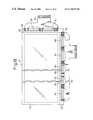
- FIG. 1is a schematic front view of part of a liquid crystal display apparatus as the first embodiment of a matrix type display apparatus according to the present invention
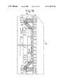
- FIG. 2is an enlarged schematic front view of part of an area for mounting data bus-driving ICs in the liquid crystal display apparatus as the first embodiment of the matrix type display apparatus according to the present invention
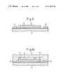
- FIG. 3is a schematic cross-sectional view illustrating a first embodiment of a method for production of the matrix type display apparatus according to the present invention
- FIG. 4is a schematic cross-sectional view illustrating the subsequent step of the first embodiment of a method for production of the matrix type display apparatus according to the present invention
- FIG. 5is a schematic cross-sectional view illustrating the subsequent step of the first embodiment of a method for production of the matrix type display apparatus according to the present invention
- FIG. 6is a schematic cross-sectional view illustrating the subsequent step of the first embodiment of a method for production of the matrix type display apparatus according to the present invention
- FIG. 7is a schematic cross-sectional view illustrating a second embodiment of a method for production of the matrix type display apparatus according to the present invention.
- FIG. 8is a schematic cross-sectional view illustrating the subsequent step of the second embodiment of a method for production of the matrix type display apparatus according to the present invention.
- FIG. 9is a schematic cross-sectional view illustrating the subsequent step of the second embodiment of a method for production of the matrix type display apparatus according to the present invention.
- FIG. 10is a schematic cross-sectional view illustrating a the subsequent step of the second embodiment of a method for production of the matrix type display apparatus according to the present invention.
- FIG. 11is a schematic cross-sectional view illustrating a third embodiment for production of the matrix type display apparatus according to the present invention.
- FIG. 12is a schematic cross-sectional view illustrating the subsequent step of the third embodiment of a method for production of the matrix type display apparatus according to the present invention.
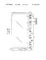
- FIG. 13is a schematic front view of part of a liquid crystal display apparatus as a second embodiment of a matrix type display apparatus according to the present invention.
- FIG. 14is an enlarged schematic front view of part of a first area for mounting data bus-driving ICs in the liquid crystal display apparatus of the second embodiment of a matrix type display apparatus according to the present invention
- FIG. 15is an enlarged schematic front view of part of a second area for mounting data bus-driving ICs in the liquid crystal display apparatus of the second embodiment of a matrix type display apparatus according to the present invention
- FIG. 16is a schematic front view of part of a liquid crystal display apparatus as a third embodiment of a matrix type display apparatus according to the present invention.
- FIG. 17is an enlarged schematic front view of part of an area for mounting data bus-driving ICs in the liquid crystal display apparatus of the third embodiment of a matrix type display apparatus according to the present invention.
- FIG. 18is an enlarged schematic front view of part of an area for mounting gate bus-driving ICs in the liquid crystal display apparatus of the third embodiment of a matrix type display apparatus according to the present invention.
- FIG. 19is a schematic front view of part of a conventional liquid crystal display apparatus of a COG system
- FIG. 20is a schematic front view of part of another conventional liquid crystal display apparatus of a COG system
- FIG. 21is a cross-sectional view of the liquid crystal display apparatus.
- FIG. 22is a schematic view illustrating the active matrix drive circuit provided on the TFT substrate.
- FIG. 1is a schematic front view of,part of a liquid crystal display apparatus according to a first embodiment of the present invention.
- reference numeral 25denotes a liquid crystal panel
- 26denotes a common substrate (first substrate) on which a common electrode is formed
- 27denotes a TFT substrate (second substrate) on which pixel electrodes, data buses, gate buses, and TFTS are formed
- 28denotes an area on which images are displayed.
- Reference numeral 29denotes an area formed in the TFT substrate 27 for mounting ICs for driving data buses; 30 to 34 denote the mounted ICs for driving the data buses; and 35 denotes a flexible circuit board (third substrate) connected to the area 29 for mounting the data bus-driving ICs.
- Reference numeral 36denotes an area provided in the TFT substrate 27 for mounting gate bus-driving ICs; and 37 denotes the mounted IC for driving the gate buses.
- FIG. 21shows a liquid crystal display apparatus which comprises a common substrate 26 , a TFT substrate 27 and a liquid crystal LC arranged between the substrates 26 and 27 .
- the liquid crystal panelalso includes a polarizer P and an analyzer A.
- the common substrate 26has a color filter 26 a , the common electrode 26 b , and an alignment layer 26 c .
- the TFT substrate 27includes picture electrodes 27 a , an alignment layer 27 b.
- FIG. 22shows an active matrix drive circuit provided on the TFT substrate 27 .
- the active matrix drive circuitincludes the picture electrodes 27 a , gate buses 27 c , data buses 27 d (data buses are represented by reference numerals 38 in FIG. 2 ), and TFTs (thin film transistors) 27 e .
- the present inventioncan be also applied to other matrix type display apparatus such as a plasma display apparatus.
- FIG. 2is an enlarged schematic front view of part of the area 29 for mounting the data bus-driving ICs 30 to 34 .
- reference numeral 38denote data buses formed in the TFT substrate 27 ;
- 39 to 54denote terminals provided in the data bus-driving IC 30 ;
- 55 to 64denote connection terminal for connection to the flexible circuit board 35 ;
- 66 to 75denote leads for connecting connection terminals 55 to 64 to the data bus-driving.
- IC 30denote data buses formed in the TFT substrate 27 ;
- 39 to 54denote terminals provided in the data bus-driving IC 30 ;
- 55 to 64denote connection terminal for connection to the flexible circuit board 35 ; and
- 66 to 75denote leads for connecting connection terminals 55 to 64 to the data bus-driving.
- IC 30denote leads for connecting connection terminals 55 to 64 to the data bus-driving.
- connection terminals similar to those 55 to 64 and leads similar to those 66 to 75 for connecting the connection terminals 55 to 64 with the data bus-driving ICsare also provided.
- connection terminalsfor example, 55 to 64 for connection to the flexible circuit board 35 are provided in the area 29 for mounting the data bus-driving ICs at positions by or on the lateral side of the shorter sides of the respective data bus-driving ICs 30 to 34 in such a manner that the connection terminals are disposed in the arrangement direction of the ICs 30 to 34 .
- the ICs 30 to 34are arranged in a row or in an approximately one row along the arrangement direction.
- the leads.for example, 66 to 75 ) for connecting the connection terminals (for example, 55 to 64 ) used for connection to the flexible circuit board 35 with the data bus-driving ICs 30 to 34 extend from the shorter sides of the data bus-driving ICs 30 to 34 .
- connection terminalsfor example, 55 to 64
- the connection terminalsfor example, 55 to 64
- the connection terminalsfor example, 55 to 64
- the connection terminals for connection to the flexible circuit board 35are disposed in the area 29 for mounting the data bus-driving ICs at positions by the shorter sides of (on the side of shorter sides of) the data bus-driving ICs 30 to 34 to be aligned in the arrangement direction of the data bus-driving ICs 30 to 34 , it is possible to reduce the width of the area 29 for mounting the data bus-driving ICs, and therefore to realize a liquid crystal display apparatus having a narrow picture frame with the area for mounting the data bus-driving ICS, on the upper or lower portion of the TFT substrate.
- the leadsextend from the shorter sides of the data bus-driving ICs 30 to, 34 , for connecting the connection terminals (for example, 55 to 64 ) used for connection to the flexible circuit board 35 with the data bus-driving ICs 30 to 34 , it is possible in this regard to reduce the width of the area 29 for mounting the data bus-driving ICs, and therefore to realize a liquid crystal display apparatus having a narrow frame with the area for mounting the data bus-driving ICs on the upper or lower side of the TFT substrate.
- FIGS. 3 to 6are schematic cross-sectional views, respectively, of part of a process for producing the liquid crystal display apparatus shown in FIGS. 1 and 2, for illustrating a first embodiment of a method for a production of a matrix type display apparatus according to the present invention.
- an anisotropic electro-conductive film 76is first linearly adhered to the area 29 for mounting data bus-driving ICs so that the data bus-driving ICs 30 to 34 and the flexible circuit board 35 can be thermo-compression bonded to the area 29 for mounting data bus-driving ICs.
- connecting parts of the flexible circuit board 35are arranged at predetermined positions in the area for mounting the data bus-driving ICs. Thereafter, as shown in FIG. 4, the flexible circuit board 35 is thermo-compression bonded to the area 29 for mounting the data bus-driving ICs by the use of a thermo-compression bonding head 77 .
- the data bus-driving ICs 30 to 34are arranged at predetermined positions in the area 29 for mounting the data bus-driving ICs, then, as shown in FIG. 6, the thermo-compression bonding head 77 is used again for thermo-compression bonding the data bus-driving ICs 30 to 34 to the area 29 for mounting the data bus-driving ICs.
- the anisotropic electro-conductive filmis linearly adhered to the area for mounting the data bus-driving ICs so that the data bus-driving ICs 30 to 34 and the flexible circuit board 35 are thermo-compression bonded thereto, the production efficiency is enhanced.
- the flexible circuit board 35is bonded to the area 29 prior to the mounting of the data bus-driving ICs 30 to 34 , while taking into account the fact that the thickness of the data bus-driving ICs 30 to 34 , which is approximately 1.0 mm, is larger than that of the flexible circuit board 35 which is approximately 0.2 mm.
- the anisotropic electro-conductive filmmight be hardened in the vicinity of the shorter sides of the data bus-driving ICs 30 to 34 .
- a distance L 1 between the respective data bus-driving IC and the flexible circuit board 35is suitably selected to be 1.0 mm or more.
- FIGS. 7 to 10are schematic cross-sectional views, respectively, of part of a process for producing the liquid crystal display apparatus shown in FIG. 1, for illustrating a second embodiment or a method for production of a matrix type display apparatus.
- an anisotropic electro-conductive film 76is first linearly adhered to the area 29 for, mounting data bus-driving ICs so that the data bus-driving ICs 30 to 34 and the flexible circuit board 35 are capable of being thermo-compression bonded to the area 29 for mounting data bus-driving ICs.
- thermo-compression bonding head 78is used to linearly bond the data bus-driving ICs 30 to 34 to the area 29 for mounting the data bus-driving ICs.
- connecting parts of the flexible circuit board 35are arranged at predetermined positions in an area 29 for mounting data bus-driving ICs, and as shown in FIG. 10, the flexible circuit board 35 is thermo-compression bonded to the area 29 for mounting the data bus-driving ICs by the use of a thermo-compression bonding head 79 .
- thermo-compression bonding head 79is a first embodiment of a thermo-compression bonding head according to the present invention, wherein a relief 70 is provided in the head so that the head is not brought into contact with each of the data bus-driving ICs 30 to 34 when the flexible circuit board 35 is thermo-contact bonded by the use of the head.
- the anisotropic electro-conductive film 76is linearly adhered to the area 29 for mounting the data bus-driving ICs so that the data bus-driving ICs 30 to 34 and the flexible circuit board 35 are thermo-compression bonded thereto, the production efficiency is enhanced.
- the data bus-driving ICs 30 to 34are bonded prior to the bonding of the flexible circuit board 35 , it is possible to avoid an inconvenience in that portions of the anisotropic electro-conductive film in the vicinity of the shorter sides of the data bus-driving ICs 30 to 34 are hardened before the data bus-driving ICs 30 to 34 have been bonded.
- FIGS. 11 to 12are schematic cross-sectional views, respectively, of part of a process for producing the liquid crystal display apparatus shown in FIG. 1, for illustrating a third embodiment of a method for production of a matrix type display apparatus according to the present invention.
- an anisotropic electro-conductive film 76is first linearly adhered to the area 29 for mounting data bus-driving ICs so that the data bus-driving ICs 30 to 34 and the flexible circuit board 35 can be thermo-compression bonded to the area 29 for mounting data bus-driving ICs.
- thermo-compression bonding head 80is used for thermo-compression bonding the data bus-driving ICs 30 to 34 and the flexible circuit board 35 at the same time to the area- 29 for mounting the data bus-driving ICs.
- thermo-compression bonding head 80is a second embodiment of a thermo-compression bonding head according to the present invention, comprising a head section 81 for bonding the data bus-driving ICs and a head section 82 for bonding the flexible circuit board 82 , wherein a height difference L 2 , between a contact portion of the head section 81 to be in contact with the data bus-driving IC and a contact portion of the head section 82 to be in contact with the flexible circuit board 35 , is selected to be equal to a thickness difference L 3 between the data bus-driving ICs 30 to 34 and the flexible circuit board 35 .
- the anisotropic electro-conductive filmis linearly adhered to the area for mounting the data bus-driving ICs so that the data bus-driving ICs 30 to 34 and the flexible circuit board 35 are thermo-compression bonded thereto, the production efficiency is enhanced.
- thermo-compression bonding head 80Since the data bus-driving ICs 30 to 34 and the flexible circuit board 35 are thermo-compression bonded at the same time to the area 29 for mounting the data bus-driving ICs by the use of the thermo-compression bonding head 80 , the production efficiency is also enhanced in this respect.
- the data bus-driving ICs 30 to 34 and the flexible circuit board 35are thermo-contact bonded at the same time to the area 29 for mounting the data bus-driving ICs, it is possible to avoid an inconvenience in that the anisotropic electro-conductive film might be hardened in the vicinity of the shorter sides of the data bus-driving ICs 30 to 34 before the data bus-driving ICs have been bonded.
- FIG. 13is a schematic front view of part of a liquid crystal display apparatus according to a second embodiment of the present invention.
- reference numeral 84denotes a liquid crystal panel
- 85denotes a common substrate on which a common electrode is formed
- 86denotes a TFT substrate on which pixel electrodes, data buses, gate buses, and TFTs are formed
- 87denotes an area on which images are displayed.
- Reference numeral 88denotes a first area formed in the TFT substrate 86 for mounting ICs for driving data buses; 89 to 93 denote the mounted ICS for driving the data buses; and 94 denotes a flexible circuit board connected to the area 88 for mounting the data bus-driving ICs.
- Reference numeral 95denotes a second area provided in the TFT substrate 86 ,for mounting data bus-driving ICs; 96 to 100 denote the mounted data bus-driving ICs; and 101 denotes the flexible circuit board.
- Reference numeral 102denotes an area provided in the TFT substrate 86 for mounting gate bus-driving ICs; and 103 denotes the mounted gate bus-driving IC.
- the data buses, gate buses or othersare not illustrated.
- FIG. 14is an enlarged schematic front view of part of the area 88 for mounting the data bus-driving IC.
- reference numeral 104denotes a data bus formed in the TFT substrate 86 ;
- 105 to 120denote terminals provided in the data bus-driving IC 89 ;
- 121 to 130denote connection terminals for connection to the flexible circuit board 94 ; and
- 131 to 140denote leads for connecting the connection terminals 121 to 130 with the data bus-driving IC 89 .
- connection terminals similar to those 121 to 130 and leads for connecting the same with the other data bus-driving ICs 90 to 93are also provided in a similar manner as described above.
- connection terminalsfor example, 121 to 130 for connection to the flexible circuit board 94 are provided in the area 88 for mounting the data bus-driving ICs at positions on the shorter sides of the respective data bus-driving ICs 89 to 93 in such a manner that the connection terminals are disposed in the arrangement direction of the ICs 89 to 93 .
- connection terminalsfor example, 121 to 130
- connection terminalsfor example, 121 to 130
- FIG. 15is an enlarged schematic front view of part of the area 95 for mounting the IC for driving the data bus.
- reference numeral 141denotes a data bus formed in the TFT substrate 86 ; 142 to 157 denote terminals provided in the data bus-driving IC 96 ; 158 to 167 denote connection terminal for connection to the flexible circuit board 101 ; and 168 to 177 denote leads for connecting connection terminals 158 to 167 to the data bus-driving IC 96 .
- connection terminals similar to those 158 to 167 and leads similar to these used for connecting the connection terminals 158 to 167 with the data bus-driving ICsare also provided.
- connection terminalsfor example, 158 to 167 ) for connection to the flexible circuit board 101 are provided in the area 95 for mounting the data bus-driving ICs at positions on the shorter sides of the respective data bus-driving ICs 96 to 100 in such a manner that the connection terminals are disposed in the arrangement direction of the ICs 96 to 100 .
- connection terminalsfor example, 158 to 167
- the leadsfor example, 168 to 177 ) for connecting the connection terminals (for example, 158 to 167 ) used for connection to the flexible circuit board 101 with the data bus-driving ICs 96 to 100 extend from the shorter sides of the data bus-driving ICs 96 to 100 .
- connection terminalsfor example, 121 to 130
- the connection terminalsfor example, 121 to 130
- the connection terminalsfor example, 121 to 130
- the connection terminalsfor example, 121 to 130
- the connection terminalsfor example, 158 to 167
- the connection terminalsfor example, 158 to 167
- the connection terminalsfor example, 158 to 167
- the leadsextend from the shorter sides of the data bus-driving ICs 89 to 93 , for connecting the connection terminals (for example, 121 to 130 ) used for connection to the flexible circuit board 94 with the data bus-driving ICs 89 to 93 and the leads (for example, 168 to 177 ) extend from the shorter sides of the data bus-driving ICs 96 to 100 , for connecting the connection terminals (for example, 158 to 167 ) used for connection to the flexible circuit board 101 with the data bus-driving ICs 796 to 100 , it is possible in this regard to reduce the width of the areas 88 , 95 for mounting the data bus-driving ICs, and therefore to realize a narrow-framed liquid crystal display apparatus having the areas for mounting the data bus-driving ICs on the upper and lower sides of the TFT substrate.
- FIG. 16is a schematic front view of part of a liquid crystal display apparatus according to a first embodiment of the present invention.
- reference numeral 179denotes a liquid crystal panel
- 180denotes a common substrate on which common electrodes are formed
- 181denotes a TFT substrate on which pixel electrodes, data buses, gate buses, TFTs or others are formed
- 182denotes an area on which images are displayed.
- Reference numeral 183denotes an area formed in the TFT substrate 181 for mounting ICs for driving data buses; 184 to 188 denotes the mounted ICs for driving the data buses; and 189 denotes a flexible circuit board connected to the area 183 for mounting the data bus-driving ICs.
- Reference numeral 190denotes an area provided in the TFT substrate 181 for mounting ICs for driving gate buses; and 191 , 192 denote the mounted ICs for driving the gate buses.
- the data buses, gate buses or othersare not shown in the drawing.
- FIG. 17is an enlarged schematic front view of part of the area 183 for mounting the data bus-driving IC.
- reference numeral 194denotes a data bus formed in the TFT substrate 181 ;
- 195 to 210denote terminals provided in the data bus-driving IC 184 ;
- 211 to 220denote connection terminal for connection to the flexible circuit board 189 ;
- 221 to 230denote leads for connecting connection terminals 211 to 220 to the data bus driving IC 184 .
- Connection terminals similar to 211 to 220 and leads used for connecting the connection terminals 221 to 230 with the data bus-driving ICs 185 to 188are also provided.
- connection terminalsfor, example, 211 to 220 for connection to the flexible circuit board 189 are provided in the area 183 -for mounting the data bus-driving ICs at positions on the shorter sides of the respective data bus-driving ICs 184 to 188 in such a manner that the connection terminals are disposed in the arrangement direction of the ICs 30 to 34 .
- connection terminalsfor example, 211 to 220
- the leadsfor example, 221 to 230 ) for connecting the connection terminals (for example, 211 to 220 ) used for connection to the flexible circuit board 189 with the data bus-driving ICs 184 to 188 extend from the shorter sides of the data bus-driving ICs 184 to 188 .
- FIG. 18is an enlarged schematic front view of part of the area 190 for mounting the IC for driving the data bus.
- reference numeral 232denotes a gate bus formed in the TFT substrate 181 ;
- 233 to 248denote terminals provided in the gate bus-driving IC 191 ;
- 249 to 258denote connection terminal for connection to the flexible circuit board 193 ;
- 259 to 268denote leads for connecting connection terminals 249 to 258 to the gate bus-driving IC 191 .
- Connection terminals similar to those 249 to 258 and leads used for connecting the connection terminals 249 to 258 with the gate bus-driving IC 192are also provided.
- connection terminalsfor example, 249 to 258 ) for connection to the flexible circuit board 193 are provided in the area 190 for mounting the gate bus-driving ICs at positions on the shorter sides of the respective gate bus-driving ICs 191 , 192 in such a manner that the connection terminals are disposed in the arrangement direction of the ICs 191 to 192 .
- connection terminalsfor example, 211 to 220
- the leadsfor example, 259 to 268 ) for connecting the connection terminals (for example, 211 to 220 ) used for connection to the flexible circuit board 193 with the gate bus-driving ICs 191 and 192 extend from the shorter sides of the gate bus-driving ICs 191 and 192 .
- connection terminalsfor example, 211 to 220
- connection terminalsfor example, 211 to 220
- the connection terminalsfor example, 211 to 220
- the connection terminalsfor example, 211 to 220
- the connection terminalsfor example, 211 to 220
- the connection terminalsfor example, 249 to 258
- the connection terminalsfor example, 249 to 258
- the connection terminalsfor example, 249 to 258
- the connection terminalsfor example, 249 to 258
- connection to the flexible circuit board 193are disposed in the area 190 for mounting the gate bus-driving ICs at positions on the shorter sides of the gate bus-driving ICs 191 and 192 to be aligned in the arrangement direction of the data bus-driving ICs 191 , 192
- the leadsextend from the shorter sides of the data bus-driving ICs 184 to 188 , for connecting the connection terminals (for example, 211 to 220 ) used for connection to the flexible circuit board 189 with the data bus-driving ICs 183 to 188
- the leadsextend from the shorter sides of the gate bus-driving ICs 191 and 192 , for connecting the connection terminals (for example, 249 to 258 ) used for connection to the flexible circuit board 193 with the gate bus-driving ICs 191 and 192
- connection terminals for connection to a third substrateare disposed in an area for mounting driving ICs at positions on the shorter sides of the driving ICs to be aligned in the arrangement direction thereof, it is possible to reduce the width of the area for mounting the driving ICs, and therefore, to realize a narrow frame liquid crystal display apparatus.
- an anisotropic electro-conductive filmis linearly adhered to the area for mounting driving ICs so that the driving ICs and the third substrate are capable of being thermo-contact bonded to the area for mounting the driving ICs, whereby it is possible to enhance the production efficiency of the apparatus.
- an anisotropic electro-conductive filmis linearly adhered to the area for mounting driving ICs so that the driving ICs and the third substrate are capable of being thermo-contact bonded to the area for mounting the driving ICs, whereby it is possible to enhance the production efficiency of the apparatus.
- the driving ICsare bonded prior to the bonding of the third substrate, it is possible to avoid an inconvenience in that a portion of the anisotropic electro-conductive film on the shorter sides of the driving ICs is hardened before the driving ICs have been bonded, and therefore, to minimize a distance between the driving ICs and the third substrate to widen a connecting portion of the third substrate so that the third substrate is firmly bonded to the area for mounting the driving ICs.
- an anisotropic electro-conductive filmis linearly adhered to the area for mounting driving ICs so that the driving ICs and the third substrate are capable of being thermo-contact bonded to the area for mounting the driving ICs, whereby it is possible to enhance the production efficiency of the apparatus.
- the production efficiencyis enhanced also in this respect.
- the driving ICs and the third substrateare thermo-contact bonded to the area for mounting the data bus-driving ICs at the same time, it is possible to avoid an inconvenience in that a portion of the anisotropic electro-conductive film on the shorter sides of the driving ICs is hardened before the driving ICs have been bonded, and therefore, to minimize a distance between the driving ICs and the third substrate to widen a connecting portion of the third substrate so that the third substrate is firmly bonded to the area for mounting the driving ICs.
- thermo-contact bonding headWhen the first embodiment of the thermo-contact bonding head according to the present invention is used, it is possible to carry out the second embodiment of the method for production of the matrix type display apparatus, which results in the enhancement of the production efficiency and the firm bonding of the third substrate to the area for mounting the driving ICS.
- thermo-contact bonding headWhen the second embodiment of the thermo-contact bonding head according to the present invention is used, it is possible to carry out the third embodiment of the method for production of the matrix type display apparatus, which results in the enhancement of the production efficiency and the firm bonding of the third substrate to the area for mounting the driving ICs.
Landscapes
- Physics & Mathematics (AREA)
- Nonlinear Science (AREA)
- General Physics & Mathematics (AREA)
- Power Engineering (AREA)
- Microelectronics & Electronic Packaging (AREA)
- Engineering & Computer Science (AREA)
- Computer Hardware Design (AREA)
- Chemical & Material Sciences (AREA)
- Optics & Photonics (AREA)
- Crystallography & Structural Chemistry (AREA)
- Mathematical Physics (AREA)
- Geometry (AREA)
- Condensed Matter Physics & Semiconductors (AREA)
- Devices For Indicating Variable Information By Combining Individual Elements (AREA)
- Liquid Crystal (AREA)
- Control Of Indicators Other Than Cathode Ray Tubes (AREA)
- Liquid Crystal Display Device Control (AREA)
- Combinations Of Printed Boards (AREA)
Abstract
Description
Claims (4)
Applications Claiming Priority (2)
| Application Number | Priority Date | Filing Date | Title |
|---|---|---|---|
| JP10347673AJP2000172193A (en) | 1998-12-08 | 1998-12-08 | Matrix display device, method of manufacturing the same, and head for thermocompression connection |
| JP10-347673 | 1998-12-08 |
Publications (1)
| Publication Number | Publication Date |
|---|---|
| US6756975B1true US6756975B1 (en) | 2004-06-29 |
Family
ID=18391812
Family Applications (1)
| Application Number | Title | Priority Date | Filing Date |
|---|---|---|---|
| US09/280,955Expired - LifetimeUS6756975B1 (en) | 1998-12-08 | 1999-03-29 | Matrix type display apparatus, method of production thereof, and thermo-compression bonding head |
Country Status (6)
| Country | Link |
|---|---|
| US (1) | US6756975B1 (en) |
| EP (2) | EP1009028A3 (en) |
| JP (1) | JP2000172193A (en) |
| KR (1) | KR100339646B1 (en) |
| CN (2) | CN100410785C (en) |
| TW (1) | TW428157B (en) |
Cited By (38)
| Publication number | Priority date | Publication date | Assignee | Title |
|---|---|---|---|---|
| US20020171638A1 (en)* | 2001-04-19 | 2002-11-21 | Hisanobu Ishiyama | Electrode driving apparatus and electronic equipment |
| US20050194657A1 (en)* | 2003-12-22 | 2005-09-08 | Seiko Epson Corporation | Electro-optical device and electronic apparatus |
| US20060072060A1 (en)* | 2004-10-05 | 2006-04-06 | Chao-Liang Lu | Flat display panel and assembly process or driver components in flat display panel |
| US20060256064A1 (en)* | 2005-05-16 | 2006-11-16 | Nec Lcd Technologies, Ltd. | Liquid crystal display device |
| US20070080166A1 (en)* | 2005-10-12 | 2007-04-12 | Rtc Industries, Inc. | Cylindrical container dispenser |
| US20070251996A1 (en)* | 2006-04-26 | 2007-11-01 | Dimitri Kanevsky | Verification of a biometric identification |
| US20080018635A1 (en)* | 1999-12-15 | 2008-01-24 | Sin-Gu Kang | Module for determining the driving signal timing and a method for driving a liquid crystal display panel |
| US7823734B2 (en) | 2005-09-12 | 2010-11-02 | Rtc Industries, Inc. | Product management display system with trackless pusher mechanism |
| JP2011049597A (en)* | 2010-11-30 | 2011-03-10 | Sony Chemical & Information Device Corp | Thermocompression head, thermocompression bonding device, and mounting method |
| US8056734B2 (en) | 2006-10-23 | 2011-11-15 | Rtc Industries, Inc. | Merchandising system with flippable column and/or item stop |
| US8312999B2 (en) | 2005-09-12 | 2012-11-20 | Rtc Industries, Inc. | Product management display system with trackless pusher mechanism |
| US8453850B2 (en) | 2005-09-12 | 2013-06-04 | Rtc Industries, Inc. | Product management display system with trackless pusher mechanism |
| US8739984B2 (en) | 2005-09-12 | 2014-06-03 | Rtc Industries, Inc. | Product management display system with trackless pusher mechanism |
| US8863963B2 (en) | 2005-09-12 | 2014-10-21 | Rtc Industries, Inc. | Product management display system with trackless pusher mechanism |
| US8967394B2 (en) | 2005-09-12 | 2015-03-03 | Rtc Industries, Inc. | Product management display system with trackless pusher mechanism |
| US8978904B2 (en) | 2005-09-12 | 2015-03-17 | Rtc Industries, Inc. | Product management display system with trackless pusher mechanism |
| US9060624B2 (en) | 2005-09-12 | 2015-06-23 | Rtc Industries, Inc. | Product management display system with rail mounting clip |
| US9138075B2 (en) | 2005-09-12 | 2015-09-22 | Rtc Industries, Inc. | Product management display system |
| US9173504B2 (en) | 2005-09-12 | 2015-11-03 | Rtc Industries, Inc. | Product management display system |
| US9232864B2 (en) | 2005-09-12 | 2016-01-12 | RTC Industries, Incorporated | Product management display system with trackless pusher mechanism |
| US9259102B2 (en) | 2005-09-12 | 2016-02-16 | RTC Industries, Incorporated | Product management display system with trackless pusher mechanism |
| US9265362B2 (en) | 2005-09-12 | 2016-02-23 | RTC Industries, Incorporated | Product management display system |
| US9265358B2 (en) | 2005-09-12 | 2016-02-23 | RTC Industries, Incorporated | Product management display system |
| US9486088B2 (en) | 2005-09-12 | 2016-11-08 | Rtc Industries, Inc. | Product management display system |
| US9750354B2 (en) | 2005-09-12 | 2017-09-05 | Rtc Industries, Inc. | Product management display system |
| USD801734S1 (en) | 2014-12-01 | 2017-11-07 | Retail Space Solutions Llc | Shelf management parts |
| US9955802B2 (en) | 2015-04-08 | 2018-05-01 | Fasteners For Retail, Inc. | Divider with selectively securable track assembly |
| US10154739B2 (en) | 2013-12-02 | 2018-12-18 | Retail Space Solutions Llc | Universal merchandiser and methods relating to same |
| US10178909B2 (en) | 2016-01-13 | 2019-01-15 | Rtc Industries, Inc. | Anti-splay device for merchandise display system |
| US10285510B2 (en) | 2005-09-12 | 2019-05-14 | Rtc Industries, Inc. | Product management display system |
| US10448756B2 (en) | 2017-06-16 | 2019-10-22 | Rtc Industries, Inc. | Product management display system with trackless pusher mechanism |
| US10952546B2 (en) | 2005-09-12 | 2021-03-23 | Rtc Industries, Inc. | Product management display system with trackless pusher mechanism |
| US10959540B2 (en) | 2016-12-05 | 2021-03-30 | Retail Space Solutions Llc | Shelf management system, components thereof, and related methods |
| US11045017B2 (en) | 2017-04-27 | 2021-06-29 | Retail Space Solutions Llc | Shelf-mounted tray and methods relating to same |
| US11259652B2 (en) | 2005-09-12 | 2022-03-01 | Rtc Industries, Inc. | Product management display system |
| US11344138B2 (en) | 2005-09-12 | 2022-05-31 | Rtc Industries, Inc. | Product management display system |
| US11583109B2 (en) | 2005-09-12 | 2023-02-21 | Rtc Industries, Inc. | Product management display system with trackless pusher mechanism |
| US20240121899A1 (en)* | 2016-11-21 | 2024-04-11 | Innolux Corporation | Display device and manufacturing method thereof |
Families Citing this family (14)
| Publication number | Priority date | Publication date | Assignee | Title |
|---|---|---|---|---|
| KR100436085B1 (en)* | 2000-10-20 | 2004-06-12 | 롬 가부시키가이샤 | Lcd and method of manufacturing semiconductor chips for a lcd |
| KR100797520B1 (en)* | 2001-08-11 | 2008-01-24 | 삼성전자주식회사 | LCD and its manufacturing method |
| KR20050035970A (en) | 2003-10-14 | 2005-04-20 | 삼성전자주식회사 | Flexible printed circuit board and liquid crystal display device using the same |
| KR100665184B1 (en)* | 2003-11-26 | 2007-01-04 | 삼성전자주식회사 | A liquid crystal display device comprising a semiconductor chip, a tape carrier package on which the chip is mounted, and the tape carrier package. |
| KR20070038771A (en) | 2005-10-06 | 2007-04-11 | 엘지전자 주식회사 | Plasma display device |
| WO2007063787A1 (en)* | 2005-12-02 | 2007-06-07 | Semiconductor Energy Laboratory Co., Ltd. | Display module and electronic device using the same |
| JP5264535B2 (en)* | 2009-01-30 | 2013-08-14 | キヤノン株式会社 | Display device |
| CN102768419B (en)* | 2011-12-05 | 2015-05-20 | 北京京东方光电科技有限公司 | COG (chip on grass) bonding technique |
| CN105225628B (en)* | 2014-06-19 | 2017-10-24 | 元太科技工业股份有限公司 | Display device, display module and pixel structure thereof |
| CN108695589B (en)* | 2017-04-07 | 2021-07-20 | 富士康(昆山)电脑接插件有限公司 | Mobile device |
| CN108615460B (en)* | 2018-04-25 | 2020-07-03 | 维沃移动通信有限公司 | Display module and mobile terminal |
| WO2020124821A1 (en)* | 2018-12-19 | 2020-06-25 | 李建国 | Narrow bezel liquid crystal display device, handheld terminal and element arrangement method |
| CN109445145A (en)* | 2018-12-19 | 2019-03-08 | 李建国 | Narrow frame liquid crystal display device, handheld terminal and element method for arranging |
| CN111601455A (en)* | 2020-06-23 | 2020-08-28 | 上海创功通讯技术有限公司 | Flexible circuit board, display module, terminal, binding system and binding method |
Citations (13)
| Publication number | Priority date | Publication date | Assignee | Title |
|---|---|---|---|---|
| US4910383A (en) | 1987-07-09 | 1990-03-20 | Productech Reflow Solder Equipment Inc. | Heated tool with differently sized and shaped heating areas |
| EP0680082A1 (en) | 1993-11-12 | 1995-11-02 | Seiko Epson Corporation | Structure and method for mounting semiconductor device and liquid crystal display device |
| US5474228A (en) | 1993-08-28 | 1995-12-12 | Kabushiki Kaisha Shinkawa | External lead bonding method and apparatus |
| US5479051A (en) | 1992-10-09 | 1995-12-26 | Fujitsu Limited | Semiconductor device having a plurality of semiconductor chips |
| JPH0845986A (en) | 1994-08-04 | 1996-02-16 | Sharp Corp | Panel mounting structure, integrated circuit mounting tape, and method of manufacturing the same |
| EP0779772A1 (en) | 1994-09-27 | 1997-06-18 | Seiko Epson Corporation | Printed wiring board, method of producing the same and electronic devices |
| US5670994A (en) | 1993-01-27 | 1997-09-23 | Sharp Kabushiki Kaisha | Assembly structure of a flat type device including a panel having electrode terminals disposed on a peripheral portion |
| WO1997037275A1 (en) | 1996-03-29 | 1997-10-09 | Seiko Epson Corporation | Liquid crystal display and apparatus using the same |
| US5712493A (en) | 1995-03-20 | 1998-01-27 | Kabushiki Kaisha Toshiba | Display device having driving circuits at the periphery of a substrate |
| US5737053A (en)* | 1995-06-05 | 1998-04-07 | Kabushiki Kaisha Toshiba | Wire substrate having branch lines perpendicular to the main lines in which the branch lines connect to driving circuits on a display device |
| US5754171A (en)* | 1992-10-21 | 1998-05-19 | Photonics Systems, Inc. | Display device having integrated circuit chips thereon |
| US5838412A (en) | 1995-11-16 | 1998-11-17 | Hitachi, Ltd. | Liquid crystal display device assembled by flip chip technology comprising a folded multi-layered flexible driving circuit substrate |
| US6211849B1 (en)* | 1996-09-24 | 2001-04-03 | Kabushiki Kaisha Toshiba | Liquid crystal display device |
Family Cites Families (6)
| Publication number | Priority date | Publication date | Assignee | Title |
|---|---|---|---|---|
| US5200847A (en)* | 1990-05-01 | 1993-04-06 | Casio Computer Co., Ltd. | Liquid crystal display device having driving circuit forming on a heat-resistant sub-substrate |
| JP3096169B2 (en)* | 1992-09-11 | 2000-10-10 | 株式会社日立製作所 | Semiconductor device |
| US5467210A (en)* | 1993-02-16 | 1995-11-14 | Casio Computer Co., Ltd. | Arrangement of bonding IC chip to liquid crystal display device |
| JPH08248432A (en)* | 1995-03-07 | 1996-09-27 | Casio Comput Co Ltd | Display panel mounting structure |
| JPH0926587A (en)* | 1995-07-11 | 1997-01-28 | Hitachi Ltd | Liquid crystal display |
| JPH0944100A (en)* | 1995-07-28 | 1997-02-14 | Toshiba Corp | Display device and IC chip used for the same |
- 1998
- 1998-12-08JPJP10347673Apatent/JP2000172193A/enactivePending
- 1999
- 1999-03-29KRKR1019990010735Apatent/KR100339646B1/ennot_activeExpired - Fee Related
- 1999-03-29USUS09/280,955patent/US6756975B1/ennot_activeExpired - Lifetime
- 1999-03-29TWTW088104945Apatent/TW428157B/enactive
- 1999-03-30EPEP99400769Apatent/EP1009028A3/ennot_activeWithdrawn
- 1999-03-30EPEP10183418Apatent/EP2282337A3/ennot_activeWithdrawn
- 1999-03-31CNCNB2005101341432Apatent/CN100410785C/ennot_activeExpired - Lifetime
- 1999-03-31CNCNB991045351Apatent/CN1242373C/ennot_activeExpired - Lifetime
Patent Citations (15)
| Publication number | Priority date | Publication date | Assignee | Title |
|---|---|---|---|---|
| US4910383A (en) | 1987-07-09 | 1990-03-20 | Productech Reflow Solder Equipment Inc. | Heated tool with differently sized and shaped heating areas |
| US5479051A (en) | 1992-10-09 | 1995-12-26 | Fujitsu Limited | Semiconductor device having a plurality of semiconductor chips |
| US5754171A (en)* | 1992-10-21 | 1998-05-19 | Photonics Systems, Inc. | Display device having integrated circuit chips thereon |
| US5670994A (en) | 1993-01-27 | 1997-09-23 | Sharp Kabushiki Kaisha | Assembly structure of a flat type device including a panel having electrode terminals disposed on a peripheral portion |
| US5474228A (en) | 1993-08-28 | 1995-12-12 | Kabushiki Kaisha Shinkawa | External lead bonding method and apparatus |
| EP0680082A1 (en) | 1993-11-12 | 1995-11-02 | Seiko Epson Corporation | Structure and method for mounting semiconductor device and liquid crystal display device |
| US5893623A (en)* | 1993-11-12 | 1999-04-13 | Seiko Epson Corporation | Structure and method for mounting semiconductor devices, and liquid crystal display |
| JPH0845986A (en) | 1994-08-04 | 1996-02-16 | Sharp Corp | Panel mounting structure, integrated circuit mounting tape, and method of manufacturing the same |
| CN1158689A (en) | 1994-09-27 | 1997-09-03 | 精工爱普生株式会社 | Printed circuit board, manufacturing method thereof, and electronic device |
| EP0779772A1 (en) | 1994-09-27 | 1997-06-18 | Seiko Epson Corporation | Printed wiring board, method of producing the same and electronic devices |
| US5712493A (en) | 1995-03-20 | 1998-01-27 | Kabushiki Kaisha Toshiba | Display device having driving circuits at the periphery of a substrate |
| US5737053A (en)* | 1995-06-05 | 1998-04-07 | Kabushiki Kaisha Toshiba | Wire substrate having branch lines perpendicular to the main lines in which the branch lines connect to driving circuits on a display device |
| US5838412A (en) | 1995-11-16 | 1998-11-17 | Hitachi, Ltd. | Liquid crystal display device assembled by flip chip technology comprising a folded multi-layered flexible driving circuit substrate |
| WO1997037275A1 (en) | 1996-03-29 | 1997-10-09 | Seiko Epson Corporation | Liquid crystal display and apparatus using the same |
| US6211849B1 (en)* | 1996-09-24 | 2001-04-03 | Kabushiki Kaisha Toshiba | Liquid crystal display device |
Cited By (99)
| Publication number | Priority date | Publication date | Assignee | Title |
|---|---|---|---|---|
| US8319718B2 (en)* | 1999-12-15 | 2012-11-27 | Samsung Display Co., Ltd. | Module for determining the driving signal timing and a method for driving a liquid crystal display panel |
| US8669929B2 (en) | 1999-12-15 | 2014-03-11 | Samsung Display Co., Ltd. | Module for determining the driving signal timing and a method for driving a liquid crystal display panel |
| US20080018635A1 (en)* | 1999-12-15 | 2008-01-24 | Sin-Gu Kang | Module for determining the driving signal timing and a method for driving a liquid crystal display panel |
| US7126571B2 (en)* | 2001-04-19 | 2006-10-24 | Seiko Epson Corporation | Electrode driving apparatus and electronic equipment |
| US20020171638A1 (en)* | 2001-04-19 | 2002-11-21 | Hisanobu Ishiyama | Electrode driving apparatus and electronic equipment |
| US20050194657A1 (en)* | 2003-12-22 | 2005-09-08 | Seiko Epson Corporation | Electro-optical device and electronic apparatus |
| US7301598B2 (en)* | 2003-12-22 | 2007-11-27 | Seiko Epson Corporation | Electro-optical device and electronic apparatus |
| US20060072060A1 (en)* | 2004-10-05 | 2006-04-06 | Chao-Liang Lu | Flat display panel and assembly process or driver components in flat display panel |
| US7515240B2 (en)* | 2004-10-05 | 2009-04-07 | Au Optronics Corporation | Flat display panel and assembly process or driver components in flat display panel |
| US20060256064A1 (en)* | 2005-05-16 | 2006-11-16 | Nec Lcd Technologies, Ltd. | Liquid crystal display device |
| CN100412667C (en)* | 2005-05-16 | 2008-08-20 | Nec液晶技术株式会社 | LCD Monitor |
| US9635957B2 (en) | 2005-09-12 | 2017-05-02 | Rtc Industries, Inc. | Product management display system |
| US11490743B2 (en) | 2005-09-12 | 2022-11-08 | Rtc Industries, Inc. | Product management display system |
| US11583109B2 (en) | 2005-09-12 | 2023-02-21 | Rtc Industries, Inc. | Product management display system with trackless pusher mechanism |
| US11517126B2 (en) | 2005-09-12 | 2022-12-06 | Rtc Industries, Inc. | Product management display system |
| US8127944B2 (en) | 2005-09-12 | 2012-03-06 | Rtc Industries, Inc. | Product management display system with trackless pusher mechanism |
| US8312999B2 (en) | 2005-09-12 | 2012-11-20 | Rtc Industries, Inc. | Product management display system with trackless pusher mechanism |
| US9895007B2 (en) | 2005-09-12 | 2018-02-20 | Rtc Industries, Inc. | Product management display system with trackless pusher mechanism |
| US8360253B2 (en) | 2005-09-12 | 2013-01-29 | Rtc Industries, Inc. | Product management display system with trackless pusher mechanism |
| US8453850B2 (en) | 2005-09-12 | 2013-06-04 | Rtc Industries, Inc. | Product management display system with trackless pusher mechanism |
| US8469205B1 (en) | 2005-09-12 | 2013-06-25 | Rtc Industries, Inc. | Product management display system with trackless pusher mechanism |
| US8550262B2 (en) | 2005-09-12 | 2013-10-08 | Rtc Industries, Inc. | Product management display system with trackless pusher mechanism |
| US11484131B2 (en) | 2005-09-12 | 2022-11-01 | Rtc Industries, Inc. | Product management display system with trackless pusher mechanism |
| US8739984B2 (en) | 2005-09-12 | 2014-06-03 | Rtc Industries, Inc. | Product management display system with trackless pusher mechanism |
| US8863963B2 (en) | 2005-09-12 | 2014-10-21 | Rtc Industries, Inc. | Product management display system with trackless pusher mechanism |
| US8967394B2 (en) | 2005-09-12 | 2015-03-03 | Rtc Industries, Inc. | Product management display system with trackless pusher mechanism |
| US8978903B2 (en) | 2005-09-12 | 2015-03-17 | Rtc Industries, Inc. | Product management display system with trackless pusher mechanism |
| US8978904B2 (en) | 2005-09-12 | 2015-03-17 | Rtc Industries, Inc. | Product management display system with trackless pusher mechanism |
| US8998005B2 (en) | 2005-09-12 | 2015-04-07 | Rtc Industries, Inc. | Product management display system with trackless pusher mechanism |
| US9060624B2 (en) | 2005-09-12 | 2015-06-23 | Rtc Industries, Inc. | Product management display system with rail mounting clip |
| US9072394B2 (en) | 2005-09-12 | 2015-07-07 | Rtc Industries, Inc. | Product management display system with trackless pusher mechanism |
| US9107515B2 (en) | 2005-09-12 | 2015-08-18 | Rtc Industries, Inc. | Product management display system with trackless pusher mechanism |
| US9138075B2 (en) | 2005-09-12 | 2015-09-22 | Rtc Industries, Inc. | Product management display system |
| US9149132B2 (en) | 2005-09-12 | 2015-10-06 | Rtc Industries, Inc. | Product management display system with trackless pusher mechanism |
| US9173504B2 (en) | 2005-09-12 | 2015-11-03 | Rtc Industries, Inc. | Product management display system |
| US9820585B2 (en) | 2005-09-12 | 2017-11-21 | Rtc Industries, Inc. | Product management display system with trackless pusher mechanism |
| US9185999B2 (en) | 2005-09-12 | 2015-11-17 | Rtc Industries, Inc. | Product management display system with trackless pusher mechanism |
| US9232864B2 (en) | 2005-09-12 | 2016-01-12 | RTC Industries, Incorporated | Product management display system with trackless pusher mechanism |
| US9237816B2 (en) | 2005-09-12 | 2016-01-19 | RTC Industries, Incorporated | Product management display system with trackless pusher mechanism |
| US9259102B2 (en) | 2005-09-12 | 2016-02-16 | RTC Industries, Incorporated | Product management display system with trackless pusher mechanism |
| US9265362B2 (en) | 2005-09-12 | 2016-02-23 | RTC Industries, Incorporated | Product management display system |
| US9265358B2 (en) | 2005-09-12 | 2016-02-23 | RTC Industries, Incorporated | Product management display system |
| US9402485B2 (en) | 2005-09-12 | 2016-08-02 | Rtc Industries, Inc. | Product management display system with trackless pusher mechanism |
| US9486088B2 (en) | 2005-09-12 | 2016-11-08 | Rtc Industries, Inc. | Product management display system |
| US9498057B2 (en) | 2005-09-12 | 2016-11-22 | Rtc Industries, Inc. | Product management display system with trackless pusher mechanism |
| US9504321B2 (en) | 2005-09-12 | 2016-11-29 | Rtc Industries, Inc. | Product management display system with trackless pusher mechanism |
| US9510677B2 (en) | 2005-09-12 | 2016-12-06 | Rtc Industries, Inc. | Product management display system with rail mounting clip |
| US9532658B2 (en) | 2005-09-12 | 2017-01-03 | Rtc Industries, Inc. | Product management display system |
| US11464346B2 (en) | 2005-09-12 | 2022-10-11 | Rtc Industries, Inc. | Product management display system |
| US9713393B2 (en) | 2005-09-12 | 2017-07-25 | Rtc Industries, Inc. | Product management display system |
| US9730531B2 (en) | 2005-09-12 | 2017-08-15 | Rtc Industries, Inc. | Product management display system with trackless pusher mechanism |
| US9750354B2 (en) | 2005-09-12 | 2017-09-05 | Rtc Industries, Inc. | Product management display system |
| US11452386B2 (en)* | 2005-09-12 | 2022-09-27 | Rtc Industries, Inc. | Product management display system with trackless pusher mechanism |
| US9173505B2 (en) | 2005-09-12 | 2015-11-03 | Rtc Industries, Inc. | Product management display system with trackless pusher mechanism |
| US11344138B2 (en) | 2005-09-12 | 2022-05-31 | Rtc Industries, Inc. | Product management display system |
| US7823734B2 (en) | 2005-09-12 | 2010-11-02 | Rtc Industries, Inc. | Product management display system with trackless pusher mechanism |
| US9918565B2 (en) | 2005-09-12 | 2018-03-20 | Rtc Industries, Inc. | Product management display system |
| US9930973B2 (en) | 2005-09-12 | 2018-04-03 | Rtc Industries, Inc. | Product management display system with trackless pusher mechanism |
| US11259652B2 (en) | 2005-09-12 | 2022-03-01 | Rtc Industries, Inc. | Product management display system |
| US9968206B2 (en) | 2005-09-12 | 2018-05-15 | Rtc Industries, Inc. | Product management display system |
| US10045640B2 (en) | 2005-09-12 | 2018-08-14 | Rtc Industries, Inc. | Product management display system with trackless pusher mechanism |
| US11076707B2 (en) | 2005-09-12 | 2021-08-03 | Rtc Industries, Inc. | Product management display system with trackless pusher mechanism |
| US10165871B2 (en) | 2005-09-12 | 2019-01-01 | Rtc Industries, Inc. | Product management display system with trackless pusher mechanism |
| US11058232B2 (en) | 2005-09-12 | 2021-07-13 | Rtc Industries, Inc. | Product management display system |
| US10206520B2 (en) | 2005-09-12 | 2019-02-19 | Rtc Industries, Inc. | Product management display system |
| US10226137B2 (en) | 2005-09-12 | 2019-03-12 | Rtc Industries, Inc. | Product management display system |
| US10278516B2 (en) | 2005-09-12 | 2019-05-07 | Rtc Industries, Inc. | Product management display system |
| US10285510B2 (en) | 2005-09-12 | 2019-05-14 | Rtc Industries, Inc. | Product management display system |
| US10966546B2 (en) | 2005-09-12 | 2021-04-06 | Rtc Industries, Inc. | Product management display system |
| US10959542B2 (en) | 2005-09-12 | 2021-03-30 | Rtc Industries, Inc. | Product management display system with trackless pusher mechanism |
| US10555624B2 (en) | 2005-09-12 | 2020-02-11 | Rtc Industries, Inc. | Product management display system with trackless pusher mechanism |
| US10568438B2 (en) | 2005-09-12 | 2020-02-25 | Rtc Industries, Inc. | Product management display system with trackless pusher mechanism |
| US9820584B2 (en) | 2005-09-12 | 2017-11-21 | Rtc Industries, Inc. | Product management display system |
| US10631666B2 (en) | 2005-09-12 | 2020-04-28 | Rtc Industries, Inc. | Product management display system |
| US10702075B2 (en) | 2005-09-12 | 2020-07-07 | Rtc Industries, Inc. | Product management display system |
| US10702079B2 (en) | 2005-09-12 | 2020-07-07 | Rtc Industries, Inc. | Product management display system with trackless pusher mechanism |
| US10905258B2 (en) | 2005-09-12 | 2021-02-02 | Rtc Industries, Inc. | Product management display system |
| US10952546B2 (en) | 2005-09-12 | 2021-03-23 | Rtc Industries, Inc. | Product management display system with trackless pusher mechanism |
| US7757890B2 (en) | 2005-10-12 | 2010-07-20 | Rtc Industries, Inc. | Cylindrical container dispenser |
| US20070080166A1 (en)* | 2005-10-12 | 2007-04-12 | Rtc Industries, Inc. | Cylindrical container dispenser |
| US20070251996A1 (en)* | 2006-04-26 | 2007-11-01 | Dimitri Kanevsky | Verification of a biometric identification |
| US8056734B2 (en) | 2006-10-23 | 2011-11-15 | Rtc Industries, Inc. | Merchandising system with flippable column and/or item stop |
| JP2011049597A (en)* | 2010-11-30 | 2011-03-10 | Sony Chemical & Information Device Corp | Thermocompression head, thermocompression bonding device, and mounting method |
| US10154739B2 (en) | 2013-12-02 | 2018-12-18 | Retail Space Solutions Llc | Universal merchandiser and methods relating to same |
| USD801734S1 (en) | 2014-12-01 | 2017-11-07 | Retail Space Solutions Llc | Shelf management parts |
| USD874197S1 (en) | 2014-12-01 | 2020-02-04 | Retail Space Solutions Llc | Shelf management dividers |
| US11690463B2 (en) | 2015-04-08 | 2023-07-04 | Fasteners For Retail, Inc. | Divider with selectively securable track assembly |
| US10588426B2 (en) | 2015-04-08 | 2020-03-17 | Fasteners For Retail, Inc. | Divider with selectively securable track assembly |
| US9955802B2 (en) | 2015-04-08 | 2018-05-01 | Fasteners For Retail, Inc. | Divider with selectively securable track assembly |
| US11122915B2 (en) | 2015-04-08 | 2021-09-21 | Fasteners For Retail, Inc. | Divider with selectively securable track assembly |
| US12185845B2 (en) | 2015-04-08 | 2025-01-07 | Fasteners For Retail, Inc. | Divider with selectively securable track assembly |
| US10178909B2 (en) | 2016-01-13 | 2019-01-15 | Rtc Industries, Inc. | Anti-splay device for merchandise display system |
| US20240121899A1 (en)* | 2016-11-21 | 2024-04-11 | Innolux Corporation | Display device and manufacturing method thereof |
| US12309931B2 (en)* | 2016-11-21 | 2025-05-20 | Innolux Corporation | Electronic device |
| US10959540B2 (en) | 2016-12-05 | 2021-03-30 | Retail Space Solutions Llc | Shelf management system, components thereof, and related methods |
| US11045017B2 (en) | 2017-04-27 | 2021-06-29 | Retail Space Solutions Llc | Shelf-mounted tray and methods relating to same |
| US10952549B2 (en) | 2017-06-16 | 2021-03-23 | Rtc Industries, Inc. | Product management display system with trackless pusher mechanism |
| US10448756B2 (en) | 2017-06-16 | 2019-10-22 | Rtc Industries, Inc. | Product management display system with trackless pusher mechanism |
| US11730286B2 (en) | 2017-06-16 | 2023-08-22 | Rtc Industries, Inc. | Product management display system with trackless pusher mechanism |
Also Published As
| Publication number | Publication date |
|---|---|
| EP2282337A3 (en) | 2012-10-17 |
| KR100339646B1 (en) | 2002-06-05 |
| CN1242373C (en) | 2006-02-15 |
| EP1009028A3 (en) | 2003-08-20 |
| CN1834732A (en) | 2006-09-20 |
| JP2000172193A (en) | 2000-06-23 |
| KR20000047378A (en) | 2000-07-25 |
| TW428157B (en) | 2001-04-01 |
| CN1256476A (en) | 2000-06-14 |
| EP1009028A2 (en) | 2000-06-14 |
| EP2282337A2 (en) | 2011-02-09 |
| CN100410785C (en) | 2008-08-13 |
Similar Documents
| Publication | Publication Date | Title |
|---|---|---|
| US6756975B1 (en) | Matrix type display apparatus, method of production thereof, and thermo-compression bonding head | |
| US7164460B2 (en) | Mounting structure for semiconductor device, electro-optical device, and electronic apparatus | |
| US7251009B2 (en) | Liquid crystal display device | |
| KR101195688B1 (en) | Flexible substrate and electric circuit structure | |
| US6025901A (en) | Liquid crystal display device and method for producing the same | |
| US7453543B2 (en) | Display device | |
| US7002809B2 (en) | Liquid crystal display driver integrated circuit package | |
| US7630048B2 (en) | Liquid crystal display device | |
| US8154120B2 (en) | Chip-mounted film package | |
| JP3979405B2 (en) | Electro-optical device, mounting structure, and electronic apparatus | |
| US8164731B2 (en) | Liquid crystal display device | |
| US6831841B2 (en) | Flexible substrate, electro-optical device and electronic device | |
| JP3498448B2 (en) | Liquid crystal display | |
| US7095406B2 (en) | Driving integrated circuit unit for a liquid crystal display device | |
| US12130510B2 (en) | Display apparatus and manufacturing method thereof | |
| US20060256064A1 (en) | Liquid crystal display device | |
| JP4343328B2 (en) | Display device | |
| KR101024648B1 (en) | LCD Display | |
| US20010046022A1 (en) | Tape carrier package with separated bonding parts, liquid crystal display employing the same and method of compensating misalignment thereof | |
| JP3575482B2 (en) | Display device | |
| JP2006066674A (en) | Electro-optical device and electronic apparatus | |
| KR101001988B1 (en) | Liquid Crystal Display and Manufacturing Method Thereof | |
| KR20060004255A (en) | Flexible film and display device having same | |
| JP3482881B2 (en) | Semiconductor mounting structure, liquid crystal device and electronic equipment | |
| JPH0996828A (en) | Liquid crystal display |
Legal Events
| Date | Code | Title | Description |
|---|---|---|---|
| AS | Assignment | Owner name:FUJITSU LIMITED, JAPAN Free format text:ASSIGNMENT OF ASSIGNORS INTEREST;ASSIGNORS:KISHIDA, KATSUHIKO;MIYAMOTO, HIROFUMI;YOSHIAKI, MARUYAMA;AND OTHERS;REEL/FRAME:009863/0696 Effective date:19990316 | |
| AS | Assignment | Owner name:FUJITSU DISPLAY TECHNOLOGIES CORPORATION, JAPAN Free format text:ASSIGNMENT OF ASSIGNORS INTEREST;ASSIGNOR:FUJITSU LIMITED;REEL/FRAME:013552/0107 Effective date:20021024 Owner name:FUJITSU DISPLAY TECHNOLOGIES CORPORATION,JAPAN Free format text:ASSIGNMENT OF ASSIGNORS INTEREST;ASSIGNOR:FUJITSU LIMITED;REEL/FRAME:013552/0107 Effective date:20021024 | |
| STCF | Information on status: patent grant | Free format text:PATENTED CASE | |
| FEPP | Fee payment procedure | Free format text:PAYOR NUMBER ASSIGNED (ORIGINAL EVENT CODE: ASPN); ENTITY STATUS OF PATENT OWNER: LARGE ENTITY | |
| AS | Assignment | Owner name:FUJITSU LIMITED,JAPAN Free format text:ASSIGNMENT OF ASSIGNORS INTEREST;ASSIGNOR:FUJITSU DISPLAY TECHNOLOGIES CORPORATION;REEL/FRAME:016345/0310 Effective date:20050630 Owner name:FUJITSU LIMITED, JAPAN Free format text:ASSIGNMENT OF ASSIGNORS INTEREST;ASSIGNOR:FUJITSU DISPLAY TECHNOLOGIES CORPORATION;REEL/FRAME:016345/0310 Effective date:20050630 | |
| AS | Assignment | Owner name:SHARP KABUSHIKI KAISHA,JAPAN Free format text:ASSIGNMENT OF ASSIGNORS INTEREST;ASSIGNOR:FUJITSU LIMITED;REEL/FRAME:016345/0210 Effective date:20050701 Owner name:SHARP KABUSHIKI KAISHA, JAPAN Free format text:ASSIGNMENT OF ASSIGNORS INTEREST;ASSIGNOR:FUJITSU LIMITED;REEL/FRAME:016345/0210 Effective date:20050701 | |
| FPAY | Fee payment | Year of fee payment:4 | |
| FPAY | Fee payment | Year of fee payment:8 | |
| FEPP | Fee payment procedure | Free format text:PAYOR NUMBER ASSIGNED (ORIGINAL EVENT CODE: ASPN); ENTITY STATUS OF PATENT OWNER: LARGE ENTITY Free format text:PAYER NUMBER DE-ASSIGNED (ORIGINAL EVENT CODE: RMPN); ENTITY STATUS OF PATENT OWNER: LARGE ENTITY | |
| FPAY | Fee payment | Year of fee payment:12 |