US6755931B2 - Apparatus and method for applying labels to a container - Google Patents
Apparatus and method for applying labels to a containerDownload PDFInfo
- Publication number
- US6755931B2 US6755931B2US10/197,742US19774202AUS6755931B2US 6755931 B2US6755931 B2US 6755931B2US 19774202 AUS19774202 AUS 19774202AUS 6755931 B2US6755931 B2US 6755931B2
- Authority
- US
- United States
- Prior art keywords
- chuck
- vial
- container
- pins
- radius
- Prior art date
- Legal status (The legal status is an assumption and is not a legal conclusion. Google has not performed a legal analysis and makes no representation as to the accuracy of the status listed.)
- Expired - Fee Related
Links
Images


Classifications
- B—PERFORMING OPERATIONS; TRANSPORTING
- B65—CONVEYING; PACKING; STORING; HANDLING THIN OR FILAMENTARY MATERIAL
- B65B—MACHINES, APPARATUS OR DEVICES FOR, OR METHODS OF, PACKAGING ARTICLES OR MATERIALS; UNPACKING
- B65B43/00—Forming, feeding, opening or setting-up containers or receptacles in association with packaging
- B65B43/42—Feeding or positioning bags, boxes, or cartons in the distended, opened, or set-up state; Feeding preformed rigid containers, e.g. tins, capsules, glass tubes, glasses, to the packaging position; Locating containers or receptacles at the filling position; Supporting containers or receptacles during the filling operation
- B65B43/46—Feeding or positioning bags, boxes, or cartons in the distended, opened, or set-up state; Feeding preformed rigid containers, e.g. tins, capsules, glass tubes, glasses, to the packaging position; Locating containers or receptacles at the filling position; Supporting containers or receptacles during the filling operation using grippers
- B—PERFORMING OPERATIONS; TRANSPORTING
- B65—CONVEYING; PACKING; STORING; HANDLING THIN OR FILAMENTARY MATERIAL
- B65B—MACHINES, APPARATUS OR DEVICES FOR, OR METHODS OF, PACKAGING ARTICLES OR MATERIALS; UNPACKING
- B65B3/00—Packaging plastic material, semiliquids, liquids or mixed solids and liquids, in individual containers or receptacles, e.g. bags, sacks, boxes, cartons, cans, or jars
- B65B3/003—Filling medical containers such as ampoules, vials, syringes or the like
- B65B3/006—Related operations, e.g. scoring ampoules
- B—PERFORMING OPERATIONS; TRANSPORTING
- B65—CONVEYING; PACKING; STORING; HANDLING THIN OR FILAMENTARY MATERIAL
- B65B—MACHINES, APPARATUS OR DEVICES FOR, OR METHODS OF, PACKAGING ARTICLES OR MATERIALS; UNPACKING
- B65B35/00—Supplying, feeding, arranging or orientating articles to be packaged
- B65B35/10—Feeding, e.g. conveying, single articles
- B65B35/16—Feeding, e.g. conveying, single articles by grippers
- Y—GENERAL TAGGING OF NEW TECHNOLOGICAL DEVELOPMENTS; GENERAL TAGGING OF CROSS-SECTIONAL TECHNOLOGIES SPANNING OVER SEVERAL SECTIONS OF THE IPC; TECHNICAL SUBJECTS COVERED BY FORMER USPC CROSS-REFERENCE ART COLLECTIONS [XRACs] AND DIGESTS
- Y10—TECHNICAL SUBJECTS COVERED BY FORMER USPC
- Y10T—TECHNICAL SUBJECTS COVERED BY FORMER US CLASSIFICATION
- Y10T156/00—Adhesive bonding and miscellaneous chemical manufacture
- Y10T156/10—Methods of surface bonding and/or assembly therefor
- Y10T156/1002—Methods of surface bonding and/or assembly therefor with permanent bending or reshaping or surface deformation of self sustaining lamina
- Y10T156/1028—Methods of surface bonding and/or assembly therefor with permanent bending or reshaping or surface deformation of self sustaining lamina by bending, drawing or stretch forming sheet to assume shape of configured lamina while in contact therewith
- Y10T156/1033—Flexible sheet to cylinder lamina
- Y—GENERAL TAGGING OF NEW TECHNOLOGICAL DEVELOPMENTS; GENERAL TAGGING OF CROSS-SECTIONAL TECHNOLOGIES SPANNING OVER SEVERAL SECTIONS OF THE IPC; TECHNICAL SUBJECTS COVERED BY FORMER USPC CROSS-REFERENCE ART COLLECTIONS [XRACs] AND DIGESTS
- Y10—TECHNICAL SUBJECTS COVERED BY FORMER USPC
- Y10T—TECHNICAL SUBJECTS COVERED BY FORMER US CLASSIFICATION
- Y10T156/00—Adhesive bonding and miscellaneous chemical manufacture
- Y10T156/17—Surface bonding means and/or assemblymeans with work feeding or handling means
- Y10T156/1702—For plural parts or plural areas of single part
- Y10T156/1744—Means bringing discrete articles into assembled relationship
- Y—GENERAL TAGGING OF NEW TECHNOLOGICAL DEVELOPMENTS; GENERAL TAGGING OF CROSS-SECTIONAL TECHNOLOGIES SPANNING OVER SEVERAL SECTIONS OF THE IPC; TECHNICAL SUBJECTS COVERED BY FORMER USPC CROSS-REFERENCE ART COLLECTIONS [XRACs] AND DIGESTS
- Y10—TECHNICAL SUBJECTS COVERED BY FORMER USPC
- Y10T—TECHNICAL SUBJECTS COVERED BY FORMER US CLASSIFICATION
- Y10T279/00—Chucks or sockets
- Y10T279/10—Expanding
- Y10T279/1074—Rotary actuator
- Y—GENERAL TAGGING OF NEW TECHNOLOGICAL DEVELOPMENTS; GENERAL TAGGING OF CROSS-SECTIONAL TECHNOLOGIES SPANNING OVER SEVERAL SECTIONS OF THE IPC; TECHNICAL SUBJECTS COVERED BY FORMER USPC CROSS-REFERENCE ART COLLECTIONS [XRACs] AND DIGESTS
- Y10—TECHNICAL SUBJECTS COVERED BY FORMER USPC
- Y10T—TECHNICAL SUBJECTS COVERED BY FORMER US CLASSIFICATION
- Y10T279/00—Chucks or sockets
- Y10T279/35—Miscellaneous
Definitions
- the present inventionrelates generally to the field of processing and packaging consumer products, particularly in the pharmaceutical industry. More specifically, the present invention relates to an apparatus and method for applying a label to a container, such as a vial for pharmaceuticals.
- Prior art labeling systemsuse various types of gripping mechanisms to secure the vial while a label is being applied.
- the prior art gripping mechanismsdo not easily adapt to handle vials having different diameters. For example, a system set up to place labels on vials with a small diameter cannot easily be converted to place labels on vials with a larger diameter.
- the labeling processmust be halted and a different sized gripping mechanism substituted to accommodate a vials of different diameters.
- alignment problemsi.e., alignment of the label relative to the vial
- vials of different heightcannot be labeled in the preferred method which is near the vial opening.
- One embodiment of the present inventionis directed to a chuck assembly comprising a housing defining a longitudinal axis and having a first end.
- a plurality of pinsextend substantially parallel with the axis from the first end.
- the plurality of pinsis located at a first radius relative to the axis with at least one of the pins being operable to move from the first radius to a second radius, relative to the axis.
- the pinsmove from the first radius to the second radius without exposing a cavity on or within the chuck assembly.
- a means for moving the at least one pin between the first radius and the second radiusis also provided.
- the means for movingmay comprise any known combination of gears, cams, and other mechanical components for imparting the desired motion to the pins.
- the chuck assembly of the present inventionmay be used in combination with various other components.
- the chuck assemblymay be used in a container labeling system comprising a printer stand, a label printer, a vial drive assembly, a stand assembly, and the chuck assembly.
- the present inventionis also directed to a method for labeling a container comprising placing a container on a gripping mechanism having a plurality of movable gripping pins for inserting into the container.
- the gripping mechanismis activated to engage the container with the gripping pins.
- the containeris brought into engagement with a source of labels and a label is applied to the container.
- the containeris taken out of engagement with the source of labels and the gripping mechanism is deactivated to disengage the gripping pins from the container.
- the present inventionenables vials of various diameters to be handled by a single device without the need to change hardware.
- the present inventionalso enables labels to be uniformly placed on vials of different lengths.
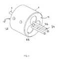
- FIG. 1is a perspective view of a chuck assembly for gripping containers of various diameters according to an embodiment of the present invention.
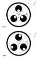
- FIG. 2is a front view of the chuck assembly of FIG. 1 with the chuck pins in a disengaged position according to an embodiment of the present invention.
- FIG. 3is a front view of the chuck assembly of FIG. 1 with the chuck pins in an engaged position according to an embodiment of the present invention.
- FIG. 4is a detailed view of the internal components of the chuck assembly of FIG. 1 according to an embodiment of the present invention.
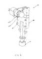
- FIG. 5is a front view of a chuck stand assembly for mounting the chuck assembly of FIG. 1 according to an embodiment of the present invention.
- FIG. 6is a rear view of the chuck stand assembly of FIG. 5 according to an embodiment of the present invention.
- FIG. 7is a perspective view of a labeling system incorporating the chuck stand assembly of FIG. 5 according to an embodiment of the present invention.
- FIG. 8is a top view of the labeling system of FIG. 7 according to an embodiment of the present invention.
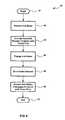
- FIG. 9is an operational process for gripping a container according to an embodiment of the present invention.
- FIG. 10illustrates the alignment of a label relative to a vial having a first length secured by the chuck assembly of FIG. 1 according to an embodiment of the present invention.
- FIG. 11illustrates the alignment of a label relative to a vial having a second length secured by the chuck assembly of FIG. 1 according to an embodiment of the present invention.
- FIG. 1is a perspective view of a chuck assembly 10 for gripping containers of various diameters according to an embodiment of the present invention.
- Chuck assembly 10is a gripping mechanism that is used to secure and transport a container, for example, to and from a station where a label is applied.
- the chuck assembly 10is comprised of a chuck body 12 , which is a housing for the various parts of chuck assembly 10 .
- Chuck assembly 10has one or more chuck pins 34 extending from a first end 13 of the chuck body 12 .
- the chuck pins 34extend substantially parallel with a longitudinal axis of the chuck body 12 , which may be a central axis.
- Each chuck pin 34may have a roller sleeve 36 associated therewith.
- each chuck pin 34is attached to a cam shaft 26 housed within the chuck body 12 .
- Each cam shaft 26may be rotated by a single drive shaft 16 which enters the chuck body 12 from a second end 15 .
- each pin 34may be rotated by its associated cam shaft 26 without exposing the interior housing of the chuck body 12 and without creating a cavity relative the chuck body 12 , the cam shafts 26 , and the chuck pins 34 , among others.
- the chuck assembly of the present inventionprevents contaminants from entering the chuck body or restricting the rotation of the cam shaft 26 and chuck pins 34 .
- FIGS. 2 and 3are front views of the chuck assembly 10 illustrated in FIG. 1 .
- FIGS. 2 and 3illustrate the chuck pins 34 in a disengaged position and in an engaged position, respectively, according to an embodiment of the present invention.
- the outer edges of chuck pins 34are positioned at a first radius relative to a point 17 laying along the longitudinal axis of the chuck body 12 .
- each chuck pin 34is attached near an outer edge of its respective cam shaft 26 , so that when cam shafts 26 are rotated, the radius measured from the chuck pins 34 to the point 17 is changed.
- the disengaged positionas illustrated in FIG. 2
- the outer edges of the chuck pins 34are at a first radius 38 .
- the disengaged positionrefers to a position in which the chuck pins 34 are not securing a container, such as a vial, that is placed over the chuck pins 34 .
- the engaged position(as illustrated in FIG. 3 )
- the outer edges of the chuck pins 34are at a second radius 39 ; the second radius 39 being larger than the first radius 38 .
- the engaged positionrefers to a position in which the chuck pins 34 secure a container, such as a vial, that is placed over the chuck pins 34 .
- the chuck pins 34begin in the disengaged position (i.e., positioned at the first radius 38 ).
- a vial(not shown) is loosely placed over the chuck pins 34 and pushed towards the chuck body 12 such that the vial comes in contact with the chuck body 12 .
- the drive shaft 16is rotated, causing each cam shaft 26 to rotate in, for example, a counter-clockwise direction.
- the drive shaft 16is rotated until the chuck pins 34 engage the vial (i.e., come into contact with the vial's inner walls).
- the second radius 39(corresponding to the engaged position) is equal to the inner radius of the vial.
- the maximum angular rotation of the cam shafts 26is limited to 120°.
- the roller sleeves 36permit an engaged vial to be rotated by a vial drive motor (not shown in FIGS. 2 and 3) while the vial is engaged by the chuck pins 34 (for example, while a label is being placed on the vial).
- a vial drive motornot shown in FIGS. 2 and 3
- the drive shaft 16is rotated in the opposite direction causing the cam shaft 26 to rotate in the clockwise direction.
- the rotating cam shafts 26cause the chuck pins 34 to disengage the vial (i.e., to travel from the second radius 39 to the first radius 38 ).
- the labeled vialis then removed from the chuck pins 34 .
- the rotational direction used to engage and disengage a vialmay be reversed (i.e., clockwise to engage, counter-clockwise to disengage) and/or mixed (i.e., one cam shaft 26 rotating clockwise with another cam shaft 26 rotating counter-clockwise) while remaining within the scope of the present invention.
- the present inventionis not intended to limit the chuck pins 34 to a rotational manner of travel.
- the chuck pins 34may move radially relative to the point 17 , from the first radius 38 to the second radius 39 .
- other componentsmay replace or accompany the drive shaft 16 and cam shafts 26 to effect the linear motion.
- a shield to eliminate the exposure of a cavity on or within the chuck body (and thus, preventing contaminants from entering the chuck body),may be associated with each pin 34 .
- FIG. 4is a detailed view of the internal components of the chuck assembly 10 of FIG. 1 according to one embodiment of the present invention.
- each chuck pin 34is attached to one end of its respective cam shaft 26 .
- a cam shaft spur gear 28is carried between a pair of cam shaft needle bearings 32 , all of which are secured to the cam shaft 26 by a cam shaft retaining ring 30 .
- three chuck pins 34are used, however, it should be noted that a different number of chuck pins 34 may be used while remaining within the scope of the present invention.
- the cam shaft spur gears 28mesh with a drive shaft spur gear 18 carried between and secured to the drive shaft 16 by a pair of drive shaft retaining rings 20 .
- a single drive shaft spur gear 18is used to mesh with each cam shaft spur gear 28 .
- multiple drive shaft spur gears 18 or multiple drive shafts 16may be used to rotate the cam shafts 26 while remaining within the scope of the present invention.
- the drive shaft 16 , drive shaft spur gear 18 , cam shafts 26 , and cam shaft spur gears 28are a means for moving the chuck pins 34 between the first radius and the second radius.
- alternative means for moving said chuck pins 34may be used while remaining within the scope of the present invention.
- a means using one or more pins, linkages, crank arms, jacks, radius bars, screw gears, winches, yokes, connecting rods, levers, toggles, cables, belts, bell cranks, clutches, pulleys, couplings and/or sprockets(among others) may be used while remaining within the scope of the present invention.
- the drive shaft 16 , drive shaft spur gear 18 , drive shaft retaining rings 20 , cam shafts 26 , cam shaft spur gears 28 , cam shaft retaining rings 30 , and cam shaft needle bearings 32 , among others,are contained with the chuck body 12 .
- the first end 13 of the chuck body 12has an opening for each chuck pin 34 .
- the chuck pins 34extend parallel with a longitudinal axis of the chuck body 12 .
- the second end 15 of the chuck body 12is located opposite the first end 13 .
- An alternating pair of bearing plates 14 and drive shaft needle bearings 22are attached to the chuck body 12 at the second end 15 .
- a prime mover(such as a rotary solenoid, electric motor, pneumatic piston, hydraulic piston, among others)(not shown in FIG. 4) is a device that is coupled to and imparts the necessary force to the means for moving the chuck pins 34 .
- a rotary solenoid 46is used as the prime mover to impart a rotational force on the drive shaft 16 .
- One of the advantages of using a rotary solenoidis the limited torque produced by the rotary solenoid.
- the rotary solenoidmay be selected so as to provide a known torque for rotating shaft 16 , and thus rotating cam shafts 26 from a minimum radius to a maximum radius. If a vial having a radius somewhere between the minimum and maximum is placed on the chuck assembly 10 , sufficient torque will be generated to rotate cam shafts 26 to bring chuck pins 34 into engagement with the inner wall of the vial.
- FIGS. 5 and 6are a front view and a back view, respectively, of a chuck stand assembly 40 for mounting the chuck assembly 10 of FIG. 1 according to an embodiment of the present invention.
- Chuck stand assembly 40includes a chuck assembly mounting plate 42 for mounting the chuck assembly 10 .
- the chuck assembly mounting plate 42is also used to mount and align a hub brake 50 , brake release 52 , rotary solenoid 46 , and flexible coupling 48 with the chuck assembly 10 .
- the chuck assembly mounting plate 42is coupled to a slide mount bracket 60 with screws 59 .
- a linear bearing 58attached to a slide mount bracket 60 and having a compression spring 56 housed within a spring pocket 54 , permits the horizontal position of the chuck assembly mounting plate 42 to be adjusted.
- a preferred horizontal positionis set such that the smallest diameter vial to be labeled will be pressed against the vial drive assembly 76 (as discussed in more detail in conjunction with FIG. 8 ).
- the labeler system 70can accommodate larger vials without changing hardware.
- the compression spring 56permits the chuck assembly mounting plate 42 to move horizontally to accommodate the larger vial.
- an actuatormay be used for adjusting the position of the chuck assembly mounting plate 42 .
- the slide mount bracket 60is attached to an actuator 66 , which is driven by a stepper motor 62 .
- the actuator 66permits the vertical position of the combination of the slide mount bracket 60 and chuck assembly 10 to be adjusted.
- a linear ball screw actuator 66is used. It should be noted that other types of actuators and motors may be used while remaining within the scope of the present invention.
- chuck stand assembly 40 of the present inventionis not intended to be limited to the chuck assembly 10 described above.
- FIGS. 7 and 8illustrate a labeling system 70 incorporating the chuck stand assembly of FIG. 5 according to an embodiment of the present invention.
- FIG. 7is a perspective view
- FIG. 8is a top view of the labeling system 70 .
- Labeling system 70includes a printer stand 72 , label printer 74 , chuck stand assembly 40 (with chuck assembly 10 ), a vial drive assembly 76 , and vial drive mount bracket 78 .
- the printer stand 72supports label printer 74 , chuck stand assembly 40 , and vial drive mount bracket 78 .
- Vial drive assembly 76includes a vial drive motor (not shown) and a vial drum (not shown). In the current embodiment, a roll of labels is fitted over the vial drum, the labels are placed in contact with a vial and the vial drive motor rotates the labels, and thus, the vial.
- the labeling system 70is configured such that a vial (not shown), which is secured by the chuck assembly 10 , is aligned with and comes into contact with a printed label 80 .
- the labeling system 70operates in the following manner.
- the actuator 66is raised by the stepper motor 62 such that the chuck assembly 10 moves away from the vial drive assembly 76 to a vial exchange position.
- the chuck pins 34are reset to the disengaged position.
- a vialis then placed over the chuck pins 34 .
- a robot arm from a prescription filling stationmay be used to place the vial over the chuck pins 34 .
- the brake release 52is activated to release hub brake 50 , thus allowing the drive shaft 16 to rotate.
- the rotary solenoid 46is then activated to move the chuck pins 34 to the engaged position. Once the chuck pins 34 reach the engaged position, the rotary solenoid 46 begins to “torque out” and the hub release 52 is deactivated.
- the hub brake 50prevents the drive shaft 16 from rotating, and thus locks the chuck pins 34 in the engaged position. Once the hub brake 50 locks the drive shaft 16 in position, the rotary solenoid 46 is deactivated.
- the actuator 66 of the chuck stand assembly 40is then lowered by the stepper motor 62 until the vial comes into contact with the vial drive assembly 76 .
- the compression spring 76permits the chuck assembly mounting plate to slightly move in the horizontal direction as required to help facilitate vials of different radii.
- Printer 74prints the desired information onto a label 80 .
- the vial drive assembly 76simultaneously rotates and applies the printed label to the vial.
- the actuator 66is raised by the stepper motor 62 until the chuck assembly 10 reaches the vial exchange position.
- the brake release 52is then activated and the hub brake 50 releases the drive shaft 16 .
- the chuck pins 34are then returned to the disengaged position.
- the vialis removed from the chuck pins 34 (for example, using the prescription filling station's robot arm).
- the next vial to be labeledmay then be placed over the chuck pins 34 .
- the operation of the brake release 52 and hub brake 50may be altered while remaining within the scope of the present invention.
- the brake release 52may be activated to engage the hub brake 50 and deactivated to release the hub brake 50 .
- the hub brake 50may prevent the movement of another means for moving (for example, a cam shaft 26 ) the chuck pins 34 while remaining within the scope of the present invention.
- the brake release 52 and hub brake 50may be combined into a single unit.
- FIG. 9is an operational process 90 for gripping a container according to an embodiment of the present invention.
- Operation 91initiates operational process 90 when a container is placed over the chuck pins 34 of the chuck assembly 10 .
- the containeris a vial.
- the vialis pushed over the chuck pins 34 (which are in the disengaged position) until the vial comes into contact with the chuck body 12 .
- Operation 92assumes control after operation 91 initiates operational process 90 .
- the hub brake 50is released, thus allowing drive shaft 16 to rotate.
- hub brake 50is released when brake release 52 is activated.
- operation 93assumes control.
- the rotary solenoid 46is activated causing the chuck pins 34 to engage the interior surface of the vial.
- the rotary solenoidrotates drive shaft 16 having drive shaft spur gear 18 that is meshed with one or more cam shaft spur gears 28 .
- Each of the cam shaft spur gears 28causes its respective cam shaft 26 to rotate, which in turn causes its associated chuck pin 34 attached at the end of the cam shaft 26 to move from the first radius 38 to the second radius 39 relative to the point 17 .
- operation 94assumes control.
- Operation 94engages the hub brake 50 when the rotary solenoid 46 begins to “torque out”.
- the rotary solenoidbegins to torque out when the chuck pins 34 come into contact with the inner walls of the vial.
- the hub release 52is deactivated causing the hub brake 50 to engage the drive shaft 16 .
- the hub brake 50prevents the drive shaft 16 from rotating.
- operation 95assumes control.
- Operation 95deactivates the rotary solenoid 46 .
- the rotary solenoidWhen the rotary solenoid is deactivated, the chuck pins 34 remain in the engaged position because the drive shaft 16 is locked in place by the hub brake 50 .
- the vialremains engaged until the hub brake 50 is released.
- the vialis now ready to be transported. Transportation in this case means to bring the vial into engagement with a source of labels.
- the vialmight be transported to other types of workstations, e.g., a capping station. After the vial has been labeled, i.e., the work station has performed its function, the vial is transported back to the vial exchange position. In the embodiment shown, transporting the vial is accomplished by the stepper motor 62 , although other means of transport may be provided.
- operation 96releases the hub brake 50 and allows the chuck pins 34 to return to the disengaged position.
- the brake release 52is activated to release the hub brake 50 and the chuck pins 34 automatically disengage the vial (for example, through the use of springs, the built-in tensioning of the cam shafts, etc.).
- Operation 97terminates operational process 90 .
- the vialmay be removed and operational process 90 repeated with another vial.
- FIGS. 10 and 11illustrates the alignment of a label 80 relative to vials 82 , 83 , respectively, secured by the chuck assembly 10 of FIG. 1 according to an embodiment of the present invention.
- vial 82has a length “Y.”
- vial 83has a length “Z,” where length Z is greater than length Y.
- Vials 82 , 83each have a set of threads 84 for securing a cap (not shown) to the vials.
- the distance (denoted “X”) from the first end 13 of chuck body 12 to an upper edge of label 80is constant.
- a gripping mechanismemploying one or more stationary chuck pins 34 in combination with at least one movable chuck pin 34 is used.
Landscapes
- Engineering & Computer Science (AREA)
- Mechanical Engineering (AREA)
- Labeling Devices (AREA)
Abstract
Description
Claims (7)
Priority Applications (7)
| Application Number | Priority Date | Filing Date | Title |
|---|---|---|---|
| US10/197,742US6755931B2 (en) | 2002-07-18 | 2002-07-18 | Apparatus and method for applying labels to a container |
| CA2492796ACA2492796C (en) | 2002-07-18 | 2003-06-13 | Apparatus and method for applying labels to a container |
| PCT/US2003/018756WO2004009449A1 (en) | 2002-07-18 | 2003-06-13 | Apparatus and method for applying labels to a container |
| AU2003248693AAU2003248693A1 (en) | 2002-07-18 | 2003-06-13 | Apparatus and method for applying labels to a container |
| EP03765444AEP1539585A1 (en) | 2002-07-18 | 2003-06-13 | Apparatus and method for applying labels to a container |
| US10/847,267US6892780B2 (en) | 2002-07-18 | 2004-05-17 | Apparatus for applying labels to a container |
| US11/063,211US20050189728A1 (en) | 2002-07-18 | 2005-02-22 | Apparatus for applying labels to a container |
Applications Claiming Priority (1)
| Application Number | Priority Date | Filing Date | Title |
|---|---|---|---|
| US10/197,742US6755931B2 (en) | 2002-07-18 | 2002-07-18 | Apparatus and method for applying labels to a container |
Related Child Applications (1)
| Application Number | Title | Priority Date | Filing Date |
|---|---|---|---|
| US10/847,267DivisionUS6892780B2 (en) | 2002-07-18 | 2004-05-17 | Apparatus for applying labels to a container |
Publications (2)
| Publication Number | Publication Date |
|---|---|
| US20040011458A1 US20040011458A1 (en) | 2004-01-22 |
| US6755931B2true US6755931B2 (en) | 2004-06-29 |
Family
ID=30442988
Family Applications (3)
| Application Number | Title | Priority Date | Filing Date |
|---|---|---|---|
| US10/197,742Expired - Fee RelatedUS6755931B2 (en) | 2002-07-18 | 2002-07-18 | Apparatus and method for applying labels to a container |
| US10/847,267Expired - Fee RelatedUS6892780B2 (en) | 2002-07-18 | 2004-05-17 | Apparatus for applying labels to a container |
| US11/063,211AbandonedUS20050189728A1 (en) | 2002-07-18 | 2005-02-22 | Apparatus for applying labels to a container |
Family Applications After (2)
| Application Number | Title | Priority Date | Filing Date |
|---|---|---|---|
| US10/847,267Expired - Fee RelatedUS6892780B2 (en) | 2002-07-18 | 2004-05-17 | Apparatus for applying labels to a container |
| US11/063,211AbandonedUS20050189728A1 (en) | 2002-07-18 | 2005-02-22 | Apparatus for applying labels to a container |
Country Status (5)
| Country | Link |
|---|---|
| US (3) | US6755931B2 (en) |
| EP (1) | EP1539585A1 (en) |
| AU (1) | AU2003248693A1 (en) |
| CA (1) | CA2492796C (en) |
| WO (1) | WO2004009449A1 (en) |
Cited By (56)
| Publication number | Priority date | Publication date | Assignee | Title |
|---|---|---|---|---|
| US20040133705A1 (en)* | 2002-08-09 | 2004-07-08 | Brian Broussard | Controller for dispensing products |
| US20040158507A1 (en)* | 2002-12-06 | 2004-08-12 | Meek Robert B. | Inventory management and replenishment system |
| US20050171813A1 (en)* | 2004-02-04 | 2005-08-04 | Jordan Mchael L. | System for identifying and sorting orders |
| US20060125356A1 (en)* | 2004-12-03 | 2006-06-15 | Mckesson Automation Inc. | Mobile point of care system and associated method and computer program product |
| US20070208457A1 (en)* | 2002-08-09 | 2007-09-06 | Mckesson Automation Systems Inc. | Method of transporting vials and cassettes in an automated prescription filling apparatus |
| US20070265730A1 (en)* | 2006-05-10 | 2007-11-15 | Mckesson Automation Inc. | System, method and corresponding apparatus for scanning an identification code of an unknown orientation |
| US20080300794A1 (en)* | 2007-05-29 | 2008-12-04 | Mckesson Automation Inc. | System, method, apparatus and computer program product for capturing human-readable text displayed on a unit dose package |
| US20080306740A1 (en)* | 2007-06-07 | 2008-12-11 | Mckesson Automation Inc. | Remotely and interactively controlling semi-automatic devices |
| US7506780B2 (en) | 2002-08-09 | 2009-03-24 | Mckesson Automation Systems Inc. | Vacuum pill dispensing cassette and counting machine |
| US20090169138A1 (en)* | 2007-12-28 | 2009-07-02 | Mckesson Automation Inc. | Medication and medical supply storage package and method |
| US20090167500A1 (en)* | 2007-12-28 | 2009-07-02 | Mckesson Automation, Inc. | Radio frequency alignment object, carriage and associated method of storing a product associated therewith |
| US20090166415A1 (en)* | 2007-12-28 | 2009-07-02 | Mckesson Automation Inc. | Proximity-based inventory management system using rfid tags to aid in dispensing and restocking inventory |
| US20090194987A1 (en)* | 2008-01-31 | 2009-08-06 | Mckesson Automation Inc. | Method, apparatus and medication storage device for efficiently generating medication labels |
| US20100241446A1 (en)* | 2009-03-23 | 2010-09-23 | Mckesson Automation Inc. | Visibly-Coded Medication Label And Associated Method, Apparatus And Computer Program Product For Providing Same |
| US20100239169A1 (en)* | 2009-03-17 | 2010-09-23 | Mckesson Automation Inc. | System And Method For Determining The Orientation Of A Unit Dose Package |
| US20100249997A1 (en)* | 2009-03-25 | 2010-09-30 | Greyshock Shawn T | System, method and corresponding apparatus for detecting perforations on a unit dose blister card |
| US20100263947A1 (en)* | 2009-04-20 | 2010-10-21 | Chris John Reichart | Method for generating electricity from solar panels for an electrical system inside a truck/semi/vehicle |
| US20110077771A1 (en)* | 2009-09-30 | 2011-03-31 | Mckesson Automation Inc. | Unit Dose Packaging And Associated Robotic Dispensing System And Method |
| US20110161108A1 (en)* | 2009-12-30 | 2011-06-30 | Mckesson Automation Inc. | Systems and methods for detecting diversion in drug dispensing |
| US7982612B2 (en) | 2009-02-20 | 2011-07-19 | Mckesson Automation Inc. | Methods, apparatuses, and computer program products for monitoring a volume of fluid in a flexible fluid bag |
| US8019470B2 (en) | 2002-12-06 | 2011-09-13 | Mckesson Automation Inc. | High capacity drawer with mechanical indicator for a dispensing device |
| US20110234419A1 (en)* | 2010-03-29 | 2011-09-29 | Mckesson Automation Inc. | Medication storage device usage status notifications |
| US20110232435A1 (en)* | 2010-03-23 | 2011-09-29 | Mckesson Automation, Inc. | Method and apparatus for facilitating cutting of a unit dose blister card |
| US8170714B2 (en) | 2003-11-26 | 2012-05-01 | Mckesson Automation, Inc. | Integrated suite of medical tools |
| US8400277B2 (en) | 2009-03-30 | 2013-03-19 | Mckesson Automation Inc. | Methods, apparatuses, and computer program products for monitoring a transfer of fluid between a syringe and a fluid reservoir |
| US8453548B2 (en) | 2010-03-23 | 2013-06-04 | Mckesson Automation Inc. | Apparatuses for cutting a unit dose blister card |
| US8474691B2 (en) | 2010-03-31 | 2013-07-02 | Mckesson Automation Inc. | System, apparatus, method and computer-readable storage medium for generating medication labels |
| US8527090B2 (en) | 2010-03-30 | 2013-09-03 | Mckesson Automation Inc. | Method, computer program product and apparatus for facilitating storage and/or retrieval of unit dose medications |
| US8554365B2 (en) | 2011-03-31 | 2013-10-08 | Mckesson Automation Inc. | Storage devices, systems, and methods for facilitating medication dispensing and restocking |
| US8571701B2 (en) | 2001-11-30 | 2013-10-29 | Mckesson Automation Inc. | Method of filling a restocking package |
| US8588964B2 (en) | 2011-03-30 | 2013-11-19 | Mckesson Automation Inc. | Storage devices, systems, and methods for dispensing medications |
| US8650042B2 (en) | 2011-09-30 | 2014-02-11 | Mckesson Automation Inc. | Case and medication tracking |
| US8660687B2 (en) | 2010-03-30 | 2014-02-25 | Mckesson Automation Inc. | Medication bin having an electronic display and an associated method and computer program product |
| US8662606B2 (en) | 2011-03-17 | 2014-03-04 | Mckesson Automation Inc. | Drawer assembly and associated method for controllably limiting the slideable extension of a drawer |
| US8694162B2 (en) | 2010-12-20 | 2014-04-08 | Mckesson Automation, Inc. | Methods, apparatuses and computer program products for utilizing near field communication to guide robots |
| US8700210B2 (en) | 2011-09-29 | 2014-04-15 | Aesynt Incorporated | Systems, methods and computer program products for visually emphasizing portions of a medication storage device |
| US8701931B2 (en) | 2011-03-30 | 2014-04-22 | Aesynt Incorporated | Medication dispensing cabinet and associated drawer assembly having pockets with controllably openable lids |
| US8755930B2 (en) | 2012-03-30 | 2014-06-17 | Aesynt Incorporated | Method, apparatus, and computer program product for optimization of item location in an automated storage system |
| US8807389B2 (en) | 2012-03-30 | 2014-08-19 | Aesynt Incorporated | Item dispensing unit |
| US8869667B2 (en) | 2009-12-04 | 2014-10-28 | Aesynt Incorporated | System, method and corresponding apparatus for singulating a unit dose blister card |
| US8869364B2 (en) | 2012-06-25 | 2014-10-28 | Aesynt Incorporated | Material separating tool |
| US8983655B2 (en) | 2012-03-26 | 2015-03-17 | Aesynt Incorporated | Automated dispensing system and method |
| US9123195B2 (en) | 2012-06-29 | 2015-09-01 | Aesynt Incorporated | Modular, multi-orientation conveyor |
| US9150119B2 (en) | 2013-03-15 | 2015-10-06 | Aesynt Incorporated | Apparatuses, systems, and methods for anticipating and delivering medications from a central pharmacy to a patient using a track based transport system |
| US9149405B2 (en) | 2009-03-03 | 2015-10-06 | Aesynt Incorporated | Medication storage and dispensing unit having a vial dispenser |
| US9171246B2 (en) | 2012-06-29 | 2015-10-27 | Aesynt Incorporated | System, methods, apparatuses, and computer program products for detecting that an object has been accessed |
| US9195803B2 (en) | 2013-03-28 | 2015-11-24 | Aesynt Incorporated | Systems, methods, apparatuses, and computer program products for providing controlled access to intravenous bags |
| US9412217B2 (en) | 2011-03-31 | 2016-08-09 | Aesynt Incorporated | Medication dispensing apparatus having conveyed carriers |
| US9443371B2 (en) | 2013-03-27 | 2016-09-13 | Aesynt Incorporated | Medication dispensing cabinet, computing device and associated method for measuring the force applied to a drawer |
| US9471750B2 (en) | 2011-09-23 | 2016-10-18 | Aesynt Incorporated | Systems, methods and computer program product for streamlined medication dispensing |
| US9511945B2 (en) | 2012-10-12 | 2016-12-06 | Aesynt Incorporated | Apparatuses, systems, and methods for transporting medications from a central pharmacy to a patient in a healthcare facility |
| US9626817B2 (en) | 2013-03-29 | 2017-04-18 | Aesynt Incorporated | Apparatuses, systems, and methods for storing and dispensing medication proximate a patient |
| US9814828B2 (en) | 2013-03-15 | 2017-11-14 | Aesynt Incorporated | Method and apparatus for preparing and monitoring an intravenous fluid bag |
| US9884695B2 (en) | 2013-03-28 | 2018-02-06 | Aesynt Incorporated | Compartment configured for presentation of stored articles |
| US9910965B2 (en) | 2011-09-16 | 2018-03-06 | Aesynt Incorporated | Systems, methods and computer program product for monitoring interactions with a medication storage device |
| US10045909B2 (en) | 2012-03-30 | 2018-08-14 | Aesynt Incorporated | Storage apparatus with support structures |
Families Citing this family (3)
| Publication number | Priority date | Publication date | Assignee | Title |
|---|---|---|---|---|
| US20130292914A1 (en)* | 2012-05-01 | 2013-11-07 | Automatic Handling, Int'l | Expandable Core Chuck |
| US10593236B1 (en) | 2018-08-24 | 2020-03-17 | Walmart Apollo, Llc | Label holder for coupling electronic labels to containers and associated methods |
| CN113456842B (en)* | 2021-07-06 | 2022-11-18 | 云南乍甸乳业有限责任公司 | Steam jet type fermentation medium heating sterilizer |
Citations (18)
| Publication number | Priority date | Publication date | Assignee | Title |
|---|---|---|---|---|
| US3058514A (en)* | 1959-11-18 | 1962-10-16 | Dennison Mfg Co | Bottle labeling machine |
| US3601261A (en) | 1968-02-15 | 1971-08-24 | Commissariat Energie Atomique | Handling grab, especially for nuclear reactor fuel elements |
| DE2621985A1 (en) | 1976-05-18 | 1977-12-01 | Oberland Glas Gmbh | Inner grab for glasses and bottles - has elastic hollow holder link pressed through opening of container and against inner faces |
| US4397710A (en)* | 1982-01-22 | 1983-08-09 | The Meyercord Co. | Machine for applying indicia to tapered or straight cylindrical articles |
| DE4039167A1 (en) | 1990-12-05 | 1992-06-11 | Mannesmann Ag | Gripper with several elements for moving objects - has direct drive for each element mounted star fashion in common base element |
| US5224586A (en)* | 1991-12-19 | 1993-07-06 | Shibuya Kogyo Co., Ltd. | Container positioning apparatus |
| US5341854A (en) | 1989-09-28 | 1994-08-30 | Alberta Research Council | Robotic drug dispensing system |
| US5421948A (en) | 1993-11-04 | 1995-06-06 | Label-Aire Inc. | Box corner labeler having a force reducer |
| US5449078A (en) | 1994-07-08 | 1995-09-12 | Thermar Corporation | Combination of a container and a safety cap therefor |
| US5570920A (en) | 1994-02-16 | 1996-11-05 | Northeastern University | Robot arm end effector |
| US5628847A (en) | 1991-11-19 | 1997-05-13 | Mcneil-Ppc, Inc. | System for applying a heat-shrinkable sleeve to a container |
| US5642906A (en) | 1993-09-16 | 1997-07-01 | Automatic Business Products Company, Inc. | Method of labelling prescription containers |
| US5798020A (en) | 1997-06-23 | 1998-08-25 | Scriptpro, Llc | Medicine vial labeler |
| US5803521A (en) | 1995-08-11 | 1998-09-08 | Balzers Und Leybold Deutschland Holding Ag | Apparatus for gripping a flat substrate |
| US5873488A (en) | 1997-07-21 | 1999-02-23 | Scriptpro, Llc | Vial gripper mechanism |
| US6036812A (en) | 1997-12-05 | 2000-03-14 | Automated Prescription Systems, Inc. | Pill dispensing system |
| US6115996A (en) | 1996-05-03 | 2000-09-12 | Kabushiki Kaisha Yuyama Seisakusho | Method of inspecting drugs contained in a vial |
| US6240394B1 (en) | 1996-12-12 | 2001-05-29 | Catalina Marketing International, Inc. | Method and apparatus for automatically generating advisory information for pharmacy patients |
Family Cites Families (17)
| Publication number | Priority date | Publication date | Assignee | Title |
|---|---|---|---|---|
| US1056435A (en)* | 1912-09-30 | 1913-03-18 | Miehle Printing Press & Mfg | Automatic centering-chuck. |
| US2310580A (en)* | 1942-07-21 | 1943-02-09 | Standard Tool And Mfg Co | Chuck |
| US2707107A (en)* | 1951-04-10 | 1955-04-26 | Clarence A Tucker | Chuck for holding finger ring |
| US2723861A (en)* | 1953-02-25 | 1955-11-15 | Eisler Charles | Centering chuck |
| US3612254A (en)* | 1970-04-24 | 1971-10-12 | Owens Illinois Inc | Container-handling chuck |
| US3806140A (en)* | 1971-06-28 | 1974-04-23 | Ethyl Dev Corp | Container holding apparatus |
| US4304398A (en)* | 1980-06-02 | 1981-12-08 | Crowell John R | Device for holding objects for fingerprinting |
| DE3434009A1 (en)* | 1984-09-15 | 1986-03-27 | Index-Werke Kg Hahn & Tessky, 7300 Esslingen | WORKPIECE HANDLING DEVICE |
| US5052736A (en)* | 1990-02-02 | 1991-10-01 | The University Of Maryland | Modular dexterous hand |
| DE4107931C1 (en)* | 1991-03-08 | 1992-02-27 | Mannesmann Ag, 4000 Duesseldorf, De | |
| US5234222A (en)* | 1991-05-31 | 1993-08-10 | Hines Industries, Inc. | Workpiece support tool |
| US5556085A (en)* | 1995-07-21 | 1996-09-17 | Cyr; Adelard N. | Work holder for eyeglasses |
| US5884951A (en)* | 1997-05-30 | 1999-03-23 | Eastman Kodak Company | Apparatus and method having short stroke arcuate motion for grasping objects |
| US6006946A (en) | 1997-12-05 | 1999-12-28 | Automated Prescriptions System, Inc. | Pill dispensing system |
| SE511958C2 (en)* | 1998-03-30 | 1999-12-20 | Bo Karl Ragnar Svensson | A gripping arrangement |
| JP3968415B2 (en)* | 2001-11-30 | 2007-08-29 | 独立行政法人産業技術総合研究所 | Gripping device |
| US6997656B2 (en)* | 2003-07-18 | 2006-02-14 | Bengston Tool + Die Co., Inc. | Device and assembly for holding an object |
- 2002
- 2002-07-18USUS10/197,742patent/US6755931B2/ennot_activeExpired - Fee Related
- 2003
- 2003-06-13AUAU2003248693Apatent/AU2003248693A1/ennot_activeAbandoned
- 2003-06-13WOPCT/US2003/018756patent/WO2004009449A1/ennot_activeApplication Discontinuation
- 2003-06-13EPEP03765444Apatent/EP1539585A1/ennot_activeWithdrawn
- 2003-06-13CACA2492796Apatent/CA2492796C/ennot_activeExpired - Fee Related
- 2004
- 2004-05-17USUS10/847,267patent/US6892780B2/ennot_activeExpired - Fee Related
- 2005
- 2005-02-22USUS11/063,211patent/US20050189728A1/ennot_activeAbandoned
Patent Citations (23)
| Publication number | Priority date | Publication date | Assignee | Title |
|---|---|---|---|---|
| US3058514A (en)* | 1959-11-18 | 1962-10-16 | Dennison Mfg Co | Bottle labeling machine |
| US3601261A (en) | 1968-02-15 | 1971-08-24 | Commissariat Energie Atomique | Handling grab, especially for nuclear reactor fuel elements |
| DE2621985A1 (en) | 1976-05-18 | 1977-12-01 | Oberland Glas Gmbh | Inner grab for glasses and bottles - has elastic hollow holder link pressed through opening of container and against inner faces |
| US4397710A (en)* | 1982-01-22 | 1983-08-09 | The Meyercord Co. | Machine for applying indicia to tapered or straight cylindrical articles |
| US5341854A (en) | 1989-09-28 | 1994-08-30 | Alberta Research Council | Robotic drug dispensing system |
| DE4039167A1 (en) | 1990-12-05 | 1992-06-11 | Mannesmann Ag | Gripper with several elements for moving objects - has direct drive for each element mounted star fashion in common base element |
| US5628847A (en) | 1991-11-19 | 1997-05-13 | Mcneil-Ppc, Inc. | System for applying a heat-shrinkable sleeve to a container |
| US5224586A (en)* | 1991-12-19 | 1993-07-06 | Shibuya Kogyo Co., Ltd. | Container positioning apparatus |
| US5642906B1 (en) | 1993-09-16 | 1999-07-20 | Automatic Business Products Co | Method of labelling prescription containers |
| US5855395A (en) | 1993-09-16 | 1999-01-05 | Automatic Business Products, Inc. | Pharmacy label and record system and method |
| US6036231A (en) | 1993-09-16 | 2000-03-14 | Automatic Business Products Company, Inc. | Pharmacy label and record system and method |
| US5642906A (en) | 1993-09-16 | 1997-07-01 | Automatic Business Products Company, Inc. | Method of labelling prescription containers |
| US5645669A (en) | 1993-11-04 | 1997-07-08 | Label-Aire, Inc. | Method for labeling transverse sides of an article |
| US5421948A (en) | 1993-11-04 | 1995-06-06 | Label-Aire Inc. | Box corner labeler having a force reducer |
| US5570920A (en) | 1994-02-16 | 1996-11-05 | Northeastern University | Robot arm end effector |
| US5449078A (en) | 1994-07-08 | 1995-09-12 | Thermar Corporation | Combination of a container and a safety cap therefor |
| US5803521A (en) | 1995-08-11 | 1998-09-08 | Balzers Und Leybold Deutschland Holding Ag | Apparatus for gripping a flat substrate |
| US6115996A (en) | 1996-05-03 | 2000-09-12 | Kabushiki Kaisha Yuyama Seisakusho | Method of inspecting drugs contained in a vial |
| US6308494B1 (en) | 1996-05-03 | 2001-10-30 | Kabushiki Kaisha Yuyama Seisakusho | Drug filling packaging and labeling machine |
| US6240394B1 (en) | 1996-12-12 | 2001-05-29 | Catalina Marketing International, Inc. | Method and apparatus for automatically generating advisory information for pharmacy patients |
| US5798020A (en) | 1997-06-23 | 1998-08-25 | Scriptpro, Llc | Medicine vial labeler |
| US5873488A (en) | 1997-07-21 | 1999-02-23 | Scriptpro, Llc | Vial gripper mechanism |
| US6036812A (en) | 1997-12-05 | 2000-03-14 | Automated Prescription Systems, Inc. | Pill dispensing system |
Non-Patent Citations (7)
| Title |
|---|
| http://www.techno-sommer.com/DsgHint19.htm, Techno Sommer automatic, Design Problems In Automation: Finding a Gripper That Eliminates Pneumatic Air Lines without Sacrificing any Power, Speed or Options!, pp. 1-2. |
| Sommer-automatic (catalog) Gripper Overview, 1 sheet. |
| Sommer-automatic GmbH 2000 (catalog), 3-Jaw Gripper sealed and rust-resistant, Type GD46, GD70, GD110, GD160, 6 sheets. |
| Sommer-automatic GmbH 2000 (catalog), 3-Jaw Gripper with T-slot Guide, Type GD304, GD306, GD308, GD310, GD312, GD316, GD320, GD380, 12 sheets. |
| Sommer-automatic GmbH 2000 (catalog), 3-Jaw Gripper, pp. 45 and 46. |
| Sommer-automatic GmbH 2000 (catalog), 3-Jaw Gripper, Type GD1, GD10, GD50, GD29, 6 sheets. |
| Sommer-automatic gmbh, www.sommer-automatic.com, Electric 3-Jaw Gripper, Type GED1302, GED1306, GED1502, GED1506, 4 sheets. |
Cited By (80)
| Publication number | Priority date | Publication date | Assignee | Title |
|---|---|---|---|---|
| US8571701B2 (en) | 2001-11-30 | 2013-10-29 | Mckesson Automation Inc. | Method of filling a restocking package |
| US7789267B2 (en) | 2002-08-09 | 2010-09-07 | Mckesson Automation Systems, Inc. | Vacuum pill dispensing cassette and counting machine |
| US20040133705A1 (en)* | 2002-08-09 | 2004-07-08 | Brian Broussard | Controller for dispensing products |
| US9037285B2 (en) | 2002-08-09 | 2015-05-19 | Mckesson Automation Systems, Inc. | Automated apparatus and method for filling vials |
| US7753229B2 (en) | 2002-08-09 | 2010-07-13 | Mckesson Automation Systems Inc. | Vacuum pill dispensing cassette and counting machine |
| US20070208457A1 (en)* | 2002-08-09 | 2007-09-06 | Mckesson Automation Systems Inc. | Method of transporting vials and cassettes in an automated prescription filling apparatus |
| US7831334B2 (en) | 2002-08-09 | 2010-11-09 | Mckesson Automation Systems Inc. | Method of transporting vials and cassettes in an automated prescription filling apparatus |
| US7506780B2 (en) | 2002-08-09 | 2009-03-24 | Mckesson Automation Systems Inc. | Vacuum pill dispensing cassette and counting machine |
| US8019470B2 (en) | 2002-12-06 | 2011-09-13 | Mckesson Automation Inc. | High capacity drawer with mechanical indicator for a dispensing device |
| US20040158507A1 (en)* | 2002-12-06 | 2004-08-12 | Meek Robert B. | Inventory management and replenishment system |
| US8170714B2 (en) | 2003-11-26 | 2012-05-01 | Mckesson Automation, Inc. | Integrated suite of medical tools |
| US20050171813A1 (en)* | 2004-02-04 | 2005-08-04 | Jordan Mchael L. | System for identifying and sorting orders |
| US20060125356A1 (en)* | 2004-12-03 | 2006-06-15 | Mckesson Automation Inc. | Mobile point of care system and associated method and computer program product |
| US20070265730A1 (en)* | 2006-05-10 | 2007-11-15 | Mckesson Automation Inc. | System, method and corresponding apparatus for scanning an identification code of an unknown orientation |
| US8483867B2 (en) | 2006-05-10 | 2013-07-09 | Mckesson Automation Inc. | System, method and corresponding apparatus for storing, retrieving and delivering unit dose blisters |
| US8036773B2 (en) | 2006-05-10 | 2011-10-11 | Mckesson Automation Inc. | System, method and corresponding apparatus for storing, retrieving and delivering unit dose blisters |
| US20070265729A1 (en)* | 2006-05-10 | 2007-11-15 | Mckesson Automation Inc. | System, method and corresponding apparatus for storing, retrieving and delivering unit dose blisters |
| US20110024444A1 (en)* | 2006-05-10 | 2011-02-03 | Mckesson Automation Inc. | System, Method and Corresponding Apparatus for Storing, Retrieving and Delivering Unit Dose Blisters |
| US20080300794A1 (en)* | 2007-05-29 | 2008-12-04 | Mckesson Automation Inc. | System, method, apparatus and computer program product for capturing human-readable text displayed on a unit dose package |
| US8009913B2 (en) | 2007-05-29 | 2011-08-30 | Mckesson Automation, Inc. | System, method, apparatus and computer program product for capturing human-readable text displayed on a unit dose package |
| US8738383B2 (en) | 2007-06-07 | 2014-05-27 | Aesynt Incorporated | Remotely and interactively controlling semi-automatic devices |
| US20080306740A1 (en)* | 2007-06-07 | 2008-12-11 | Mckesson Automation Inc. | Remotely and interactively controlling semi-automatic devices |
| US20090166415A1 (en)* | 2007-12-28 | 2009-07-02 | Mckesson Automation Inc. | Proximity-based inventory management system using rfid tags to aid in dispensing and restocking inventory |
| US8006903B2 (en) | 2007-12-28 | 2011-08-30 | Mckesson Automation, Inc. | Proximity-based inventory management system using RFID tags to aid in dispensing and restocking inventory |
| US20090169138A1 (en)* | 2007-12-28 | 2009-07-02 | Mckesson Automation Inc. | Medication and medical supply storage package and method |
| US20090167500A1 (en)* | 2007-12-28 | 2009-07-02 | Mckesson Automation, Inc. | Radio frequency alignment object, carriage and associated method of storing a product associated therewith |
| US8094028B2 (en) | 2007-12-28 | 2012-01-10 | Mckesson Automation, Inc. | Radio frequency alignment object, carriage and associated method of storing a product associated therewith |
| US20090194987A1 (en)* | 2008-01-31 | 2009-08-06 | Mckesson Automation Inc. | Method, apparatus and medication storage device for efficiently generating medication labels |
| US7982612B2 (en) | 2009-02-20 | 2011-07-19 | Mckesson Automation Inc. | Methods, apparatuses, and computer program products for monitoring a volume of fluid in a flexible fluid bag |
| US9149405B2 (en) | 2009-03-03 | 2015-10-06 | Aesynt Incorporated | Medication storage and dispensing unit having a vial dispenser |
| US8929641B2 (en) | 2009-03-17 | 2015-01-06 | Aesynt Incorporated | System and method for determining the orientation of a unit dose package |
| US20100239169A1 (en)* | 2009-03-17 | 2010-09-23 | Mckesson Automation Inc. | System And Method For Determining The Orientation Of A Unit Dose Package |
| US9779507B2 (en) | 2009-03-17 | 2017-10-03 | Aesynt Incorporated | System and method for determining the orientation of a unit dose package |
| US20100241446A1 (en)* | 2009-03-23 | 2010-09-23 | Mckesson Automation Inc. | Visibly-Coded Medication Label And Associated Method, Apparatus And Computer Program Product For Providing Same |
| US8405875B2 (en) | 2009-03-23 | 2013-03-26 | Mckesson Automation Inc. | Visibly-coded medication label and associated method, apparatus and computer program product for providing same |
| US20100249997A1 (en)* | 2009-03-25 | 2010-09-30 | Greyshock Shawn T | System, method and corresponding apparatus for detecting perforations on a unit dose blister card |
| US8869663B2 (en) | 2009-03-25 | 2014-10-28 | Aesynt Incorporated | System, method and corresponding apparatus for detecting perforations on a unit dose blister card |
| US8400277B2 (en) | 2009-03-30 | 2013-03-19 | Mckesson Automation Inc. | Methods, apparatuses, and computer program products for monitoring a transfer of fluid between a syringe and a fluid reservoir |
| US20100263947A1 (en)* | 2009-04-20 | 2010-10-21 | Chris John Reichart | Method for generating electricity from solar panels for an electrical system inside a truck/semi/vehicle |
| US8644982B2 (en) | 2009-09-30 | 2014-02-04 | Mckesson Automation Inc. | Unit dose packaging and associated robotic dispensing system and method |
| US20110077771A1 (en)* | 2009-09-30 | 2011-03-31 | Mckesson Automation Inc. | Unit Dose Packaging And Associated Robotic Dispensing System And Method |
| US8869667B2 (en) | 2009-12-04 | 2014-10-28 | Aesynt Incorporated | System, method and corresponding apparatus for singulating a unit dose blister card |
| US20110161108A1 (en)* | 2009-12-30 | 2011-06-30 | Mckesson Automation Inc. | Systems and methods for detecting diversion in drug dispensing |
| US8640586B2 (en) | 2010-03-23 | 2014-02-04 | Mckesson Automation Inc. | Method and apparatus for facilitating cutting of a unit dose blister card |
| US20110232435A1 (en)* | 2010-03-23 | 2011-09-29 | Mckesson Automation, Inc. | Method and apparatus for facilitating cutting of a unit dose blister card |
| US8453548B2 (en) | 2010-03-23 | 2013-06-04 | Mckesson Automation Inc. | Apparatuses for cutting a unit dose blister card |
| US8593278B2 (en) | 2010-03-29 | 2013-11-26 | Mckesson Automation Inc. | Medication storage device usage status notifications |
| US20110234419A1 (en)* | 2010-03-29 | 2011-09-29 | Mckesson Automation Inc. | Medication storage device usage status notifications |
| US8660687B2 (en) | 2010-03-30 | 2014-02-25 | Mckesson Automation Inc. | Medication bin having an electronic display and an associated method and computer program product |
| US8527090B2 (en) | 2010-03-30 | 2013-09-03 | Mckesson Automation Inc. | Method, computer program product and apparatus for facilitating storage and/or retrieval of unit dose medications |
| US8474691B2 (en) | 2010-03-31 | 2013-07-02 | Mckesson Automation Inc. | System, apparatus, method and computer-readable storage medium for generating medication labels |
| US8694162B2 (en) | 2010-12-20 | 2014-04-08 | Mckesson Automation, Inc. | Methods, apparatuses and computer program products for utilizing near field communication to guide robots |
| US8662606B2 (en) | 2011-03-17 | 2014-03-04 | Mckesson Automation Inc. | Drawer assembly and associated method for controllably limiting the slideable extension of a drawer |
| US8588964B2 (en) | 2011-03-30 | 2013-11-19 | Mckesson Automation Inc. | Storage devices, systems, and methods for dispensing medications |
| US8701931B2 (en) | 2011-03-30 | 2014-04-22 | Aesynt Incorporated | Medication dispensing cabinet and associated drawer assembly having pockets with controllably openable lids |
| US8554365B2 (en) | 2011-03-31 | 2013-10-08 | Mckesson Automation Inc. | Storage devices, systems, and methods for facilitating medication dispensing and restocking |
| US9412217B2 (en) | 2011-03-31 | 2016-08-09 | Aesynt Incorporated | Medication dispensing apparatus having conveyed carriers |
| US9910965B2 (en) | 2011-09-16 | 2018-03-06 | Aesynt Incorporated | Systems, methods and computer program product for monitoring interactions with a medication storage device |
| US9471750B2 (en) | 2011-09-23 | 2016-10-18 | Aesynt Incorporated | Systems, methods and computer program product for streamlined medication dispensing |
| US8700210B2 (en) | 2011-09-29 | 2014-04-15 | Aesynt Incorporated | Systems, methods and computer program products for visually emphasizing portions of a medication storage device |
| US8650042B2 (en) | 2011-09-30 | 2014-02-11 | Mckesson Automation Inc. | Case and medication tracking |
| US8983655B2 (en) | 2012-03-26 | 2015-03-17 | Aesynt Incorporated | Automated dispensing system and method |
| US8807389B2 (en) | 2012-03-30 | 2014-08-19 | Aesynt Incorporated | Item dispensing unit |
| US8755930B2 (en) | 2012-03-30 | 2014-06-17 | Aesynt Incorporated | Method, apparatus, and computer program product for optimization of item location in an automated storage system |
| US10045909B2 (en) | 2012-03-30 | 2018-08-14 | Aesynt Incorporated | Storage apparatus with support structures |
| US8869364B2 (en) | 2012-06-25 | 2014-10-28 | Aesynt Incorporated | Material separating tool |
| US9123195B2 (en) | 2012-06-29 | 2015-09-01 | Aesynt Incorporated | Modular, multi-orientation conveyor |
| US9171246B2 (en) | 2012-06-29 | 2015-10-27 | Aesynt Incorporated | System, methods, apparatuses, and computer program products for detecting that an object has been accessed |
| US11694782B2 (en) | 2012-10-12 | 2023-07-04 | Omnicell, Inc. | Apparatuses, systems, and methods for transporting medications from a central pharmacy to a patient in a healthcare facility |
| US10850926B2 (en) | 2012-10-12 | 2020-12-01 | Omnicell, Inc. | Apparatuses, systems, and methods for transporting medications from a central pharmacy to a patient in a healthcare facility |
| US9511945B2 (en) | 2012-10-12 | 2016-12-06 | Aesynt Incorporated | Apparatuses, systems, and methods for transporting medications from a central pharmacy to a patient in a healthcare facility |
| US10518981B2 (en) | 2012-10-12 | 2019-12-31 | Aesynt Incorporated | Apparatuses, systems, and methods for transporting medications from a central pharmacy to a patient in a healthcare facility |
| US10315851B2 (en) | 2012-10-12 | 2019-06-11 | Aesynt Incorporated | Apparatuses, systems, and methods for transporting medications from a central pharmacy to a patient in a healthcare facility |
| US10029856B2 (en) | 2012-10-12 | 2018-07-24 | Aesynt Incorporated | Apparatuses, systems, and methods for transporting medications from a central pharmacy to a patient in a healthcare facility |
| US9814828B2 (en) | 2013-03-15 | 2017-11-14 | Aesynt Incorporated | Method and apparatus for preparing and monitoring an intravenous fluid bag |
| US9150119B2 (en) | 2013-03-15 | 2015-10-06 | Aesynt Incorporated | Apparatuses, systems, and methods for anticipating and delivering medications from a central pharmacy to a patient using a track based transport system |
| US9443371B2 (en) | 2013-03-27 | 2016-09-13 | Aesynt Incorporated | Medication dispensing cabinet, computing device and associated method for measuring the force applied to a drawer |
| US9884695B2 (en) | 2013-03-28 | 2018-02-06 | Aesynt Incorporated | Compartment configured for presentation of stored articles |
| US9195803B2 (en) | 2013-03-28 | 2015-11-24 | Aesynt Incorporated | Systems, methods, apparatuses, and computer program products for providing controlled access to intravenous bags |
| US9626817B2 (en) | 2013-03-29 | 2017-04-18 | Aesynt Incorporated | Apparatuses, systems, and methods for storing and dispensing medication proximate a patient |
Also Published As
| Publication number | Publication date |
|---|---|
| US20050189728A1 (en) | 2005-09-01 |
| EP1539585A1 (en) | 2005-06-15 |
| CA2492796C (en) | 2010-08-17 |
| US6892780B2 (en) | 2005-05-17 |
| US20040011458A1 (en) | 2004-01-22 |
| US20040211524A1 (en) | 2004-10-28 |
| AU2003248693A1 (en) | 2004-02-09 |
| WO2004009449A8 (en) | 2004-05-27 |
| CA2492796A1 (en) | 2004-01-29 |
| WO2004009449A1 (en) | 2004-01-29 |
Similar Documents
| Publication | Publication Date | Title |
|---|---|---|
| US6755931B2 (en) | Apparatus and method for applying labels to a container | |
| US6308816B1 (en) | Rotary orienter indexing system | |
| CN112858342B (en) | Transparent box body fully automatic image defect detection device | |
| EP2298510A1 (en) | Robot with delta kinematics | |
| US20100242762A1 (en) | Marking or labeling machine and method | |
| GB2026701A (en) | Imbalance determining system | |
| US20180304644A1 (en) | Apparatus and method for printing on containers | |
| US8028816B1 (en) | Container handling system | |
| US20070084361A1 (en) | Transfer device for transferring an article in a printing machine, a printing machine and a method of transfer | |
| JPH11314752A (en) | Bottle conveyor system | |
| EP3435145A1 (en) | Device and method for removing film from a display device | |
| JP2024022544A (en) | Apparatus for automatically replacing printing sleeves | |
| AU2002332859A1 (en) | Rotary pick and place technology | |
| WO2003020615A2 (en) | Rotary pick and place technology | |
| CA2640156A1 (en) | Vertical banding machine | |
| US3564998A (en) | Chuck for manipulating bottles in a bottle decorating apparatus | |
| US20100089005A1 (en) | Vertical banding machine | |
| EP1498371B1 (en) | Rotary conveyor | |
| US20230183013A1 (en) | Movement system for container-retaining devices and transport equipment for retaining and transporting a container | |
| JP2697536B2 (en) | Clamp type container transfer device | |
| JP4229801B2 (en) | Container transfer device | |
| GB2067501A (en) | Transfer apparatus | |
| JP4306869B2 (en) | Label expansion mechanism | |
| JP4141370B2 (en) | Cap tightening device | |
| US6786482B2 (en) | Material handler apparatus |
Legal Events
| Date | Code | Title | Description |
|---|---|---|---|
| AS | Assignment | Owner name:MCKESSON AUTOMATION SYSTEMS INC., PENNSYLVANIA Free format text:ASSIGNMENT OF ASSIGNORS INTEREST;ASSIGNORS:VOLLM, JAMES;WANGU, MANOJ;HILL, JEFFREY;REEL/FRAME:013116/0737 Effective date:20020712 | |
| CC | Certificate of correction | ||
| FEPP | Fee payment procedure | Free format text:PAT HOLDER CLAIMS SMALL ENTITY STATUS, ENTITY STATUS SET TO SMALL (ORIGINAL EVENT CODE: LTOS); ENTITY STATUS OF PATENT OWNER: LARGE ENTITY | |
| FEPP | Fee payment procedure | Free format text:PAYOR NUMBER ASSIGNED (ORIGINAL EVENT CODE: ASPN); ENTITY STATUS OF PATENT OWNER: LARGE ENTITY | |
| AS | Assignment | Owner name:PARATA SYSTEMS, LLC, NORTH CAROLINA Free format text:ASSIGNMENT OF ASSIGNORS INTEREST;ASSIGNORS:MCKESSON AUTOMATION SYSTEMS INC.;D & K HEALTHCARE RESOURCES LLC;REEL/FRAME:018239/0063 Effective date:20060817 | |
| FEPP | Fee payment procedure | Free format text:PAT HOLDER NO LONGER CLAIMS SMALL ENTITY STATUS, ENTITY STATUS SET TO UNDISCOUNTED (ORIGINAL EVENT CODE: STOL); ENTITY STATUS OF PATENT OWNER: LARGE ENTITY | |
| FEPP | Fee payment procedure | Free format text:PAYER NUMBER DE-ASSIGNED (ORIGINAL EVENT CODE: RMPN); ENTITY STATUS OF PATENT OWNER: LARGE ENTITY Free format text:PAYOR NUMBER ASSIGNED (ORIGINAL EVENT CODE: ASPN); ENTITY STATUS OF PATENT OWNER: LARGE ENTITY | |
| FPAY | Fee payment | Year of fee payment:4 | |
| REMI | Maintenance fee reminder mailed | ||
| FPAY | Fee payment | Year of fee payment:8 | |
| REMI | Maintenance fee reminder mailed | ||
| LAPS | Lapse for failure to pay maintenance fees | ||
| STCH | Information on status: patent discontinuation | Free format text:PATENT EXPIRED DUE TO NONPAYMENT OF MAINTENANCE FEES UNDER 37 CFR 1.362 | |
| FP | Lapsed due to failure to pay maintenance fee | Effective date:20160629 | |
| AS | Assignment | Owner name:KKR LOAN ADMINISTRATION SERVICES LLC, NEW YORK Free format text:SECURITY INTEREST;ASSIGNORS:CHUDY GROUP, LLC;PARATA SYSTEMS, LLC;REEL/FRAME:056750/0811 Effective date:20210630 | |
| AS | Assignment | Owner name:CHUDY GROUP, LLC, WISCONSIN Free format text:RELEASE BY SECURED PARTY;ASSIGNOR:KKR LOAN ADMINISTRATION SERVICES LLC;REEL/FRAME:060693/0569 Effective date:20220715 Owner name:PARATA SYSTEMS, LLC, NORTH CAROLINA Free format text:RELEASE BY SECURED PARTY;ASSIGNOR:KKR LOAN ADMINISTRATION SERVICES LLC;REEL/FRAME:060693/0569 Effective date:20220715 |