US6755840B2 - Apparatus and method for tibial fixation of soft tissue - Google Patents
Apparatus and method for tibial fixation of soft tissueDownload PDFInfo
- Publication number
- US6755840B2 US6755840B2US10/167,074US16707402AUS6755840B2US 6755840 B2US6755840 B2US 6755840B2US 16707402 AUS16707402 AUS 16707402AUS 6755840 B2US6755840 B2US 6755840B2
- Authority
- US
- United States
- Prior art keywords
- guide
- operable
- bore
- elongated body
- instrument
- Prior art date
- Legal status (The legal status is an assumption and is not a legal conclusion. Google has not performed a legal analysis and makes no representation as to the accuracy of the status listed.)
- Expired - Lifetime
Links
Images


Classifications
- A—HUMAN NECESSITIES
- A61—MEDICAL OR VETERINARY SCIENCE; HYGIENE
- A61F—FILTERS IMPLANTABLE INTO BLOOD VESSELS; PROSTHESES; DEVICES PROVIDING PATENCY TO, OR PREVENTING COLLAPSING OF, TUBULAR STRUCTURES OF THE BODY, e.g. STENTS; ORTHOPAEDIC, NURSING OR CONTRACEPTIVE DEVICES; FOMENTATION; TREATMENT OR PROTECTION OF EYES OR EARS; BANDAGES, DRESSINGS OR ABSORBENT PADS; FIRST-AID KITS
- A61F2/00—Filters implantable into blood vessels; Prostheses, i.e. artificial substitutes or replacements for parts of the body; Appliances for connecting them with the body; Devices providing patency to, or preventing collapsing of, tubular structures of the body, e.g. stents
- A61F2/02—Prostheses implantable into the body
- A61F2/08—Muscles; Tendons; Ligaments
- A61F2/0811—Fixation devices for tendons or ligaments
- A—HUMAN NECESSITIES
- A61—MEDICAL OR VETERINARY SCIENCE; HYGIENE
- A61B—DIAGNOSIS; SURGERY; IDENTIFICATION
- A61B17/00—Surgical instruments, devices or methods
- A61B17/064—Surgical staples, i.e. penetrating the tissue
- A61B17/0642—Surgical staples, i.e. penetrating the tissue for bones, e.g. for osteosynthesis or connecting tendon to bone
- A—HUMAN NECESSITIES
- A61—MEDICAL OR VETERINARY SCIENCE; HYGIENE
- A61B—DIAGNOSIS; SURGERY; IDENTIFICATION
- A61B17/00—Surgical instruments, devices or methods
- A61B17/16—Instruments for performing osteoclasis; Drills or chisels for bones; Trepans
- A61B17/17—Guides or aligning means for drills, mills, pins or wires
- A61B17/1714—Guides or aligning means for drills, mills, pins or wires for applying tendons or ligaments
- A—HUMAN NECESSITIES
- A61—MEDICAL OR VETERINARY SCIENCE; HYGIENE
- A61B—DIAGNOSIS; SURGERY; IDENTIFICATION
- A61B17/00—Surgical instruments, devices or methods
- A61B17/16—Instruments for performing osteoclasis; Drills or chisels for bones; Trepans
- A61B17/1604—Chisels; Rongeurs; Punches; Stamps
- A—HUMAN NECESSITIES
- A61—MEDICAL OR VETERINARY SCIENCE; HYGIENE
- A61B—DIAGNOSIS; SURGERY; IDENTIFICATION
- A61B17/00—Surgical instruments, devices or methods
- A61B17/16—Instruments for performing osteoclasis; Drills or chisels for bones; Trepans
- A61B17/1662—Instruments for performing osteoclasis; Drills or chisels for bones; Trepans for particular parts of the body
- A61B17/1675—Instruments for performing osteoclasis; Drills or chisels for bones; Trepans for particular parts of the body for the knee
- A—HUMAN NECESSITIES
- A61—MEDICAL OR VETERINARY SCIENCE; HYGIENE
- A61B—DIAGNOSIS; SURGERY; IDENTIFICATION
- A61B17/00—Surgical instruments, devices or methods
- A61B17/16—Instruments for performing osteoclasis; Drills or chisels for bones; Trepans
- A61B17/17—Guides or aligning means for drills, mills, pins or wires
- A61B17/1739—Guides or aligning means for drills, mills, pins or wires specially adapted for particular parts of the body
- A61B17/1764—Guides or aligning means for drills, mills, pins or wires specially adapted for particular parts of the body for the knee
- A—HUMAN NECESSITIES
- A61—MEDICAL OR VETERINARY SCIENCE; HYGIENE
- A61B—DIAGNOSIS; SURGERY; IDENTIFICATION
- A61B17/00—Surgical instruments, devices or methods
- A61B17/56—Surgical instruments or methods for treatment of bones or joints; Devices specially adapted therefor
- A61B17/58—Surgical instruments or methods for treatment of bones or joints; Devices specially adapted therefor for osteosynthesis, e.g. bone plates, screws or setting implements
- A61B17/88—Osteosynthesis instruments; Methods or means for implanting or extracting internal or external fixation devices
- A61B17/8872—Instruments for putting said fixation devices against or away from the bone
- A—HUMAN NECESSITIES
- A61—MEDICAL OR VETERINARY SCIENCE; HYGIENE
- A61B—DIAGNOSIS; SURGERY; IDENTIFICATION
- A61B17/00—Surgical instruments, devices or methods
- A61B17/064—Surgical staples, i.e. penetrating the tissue
- A61B2017/0641—Surgical staples, i.e. penetrating the tissue having at least three legs as part of one single body
- A—HUMAN NECESSITIES
- A61—MEDICAL OR VETERINARY SCIENCE; HYGIENE
- A61B—DIAGNOSIS; SURGERY; IDENTIFICATION
- A61B17/00—Surgical instruments, devices or methods
- A61B17/064—Surgical staples, i.e. penetrating the tissue
- A61B2017/0647—Surgical staples, i.e. penetrating the tissue having one single leg, e.g. tacks
- A61B2017/0648—Surgical staples, i.e. penetrating the tissue having one single leg, e.g. tacks threaded, e.g. tacks with a screw thread
- A—HUMAN NECESSITIES
- A61—MEDICAL OR VETERINARY SCIENCE; HYGIENE
- A61B—DIAGNOSIS; SURGERY; IDENTIFICATION
- A61B90/00—Instruments, implements or accessories specially adapted for surgery or diagnosis and not covered by any of the groups A61B1/00 - A61B50/00, e.g. for luxation treatment or for protecting wound edges
- A61B90/03—Automatic limiting or abutting means, e.g. for safety
- A61B2090/033—Abutting means, stops, e.g. abutting on tissue or skin
- A61B2090/034—Abutting means, stops, e.g. abutting on tissue or skin abutting on parts of the device itself
- A—HUMAN NECESSITIES
- A61—MEDICAL OR VETERINARY SCIENCE; HYGIENE
- A61F—FILTERS IMPLANTABLE INTO BLOOD VESSELS; PROSTHESES; DEVICES PROVIDING PATENCY TO, OR PREVENTING COLLAPSING OF, TUBULAR STRUCTURES OF THE BODY, e.g. STENTS; ORTHOPAEDIC, NURSING OR CONTRACEPTIVE DEVICES; FOMENTATION; TREATMENT OR PROTECTION OF EYES OR EARS; BANDAGES, DRESSINGS OR ABSORBENT PADS; FIRST-AID KITS
- A61F2/00—Filters implantable into blood vessels; Prostheses, i.e. artificial substitutes or replacements for parts of the body; Appliances for connecting them with the body; Devices providing patency to, or preventing collapsing of, tubular structures of the body, e.g. stents
- A61F2/02—Prostheses implantable into the body
- A61F2/08—Muscles; Tendons; Ligaments
- A61F2/0805—Implements for inserting tendons or ligaments
- A—HUMAN NECESSITIES
- A61—MEDICAL OR VETERINARY SCIENCE; HYGIENE
- A61F—FILTERS IMPLANTABLE INTO BLOOD VESSELS; PROSTHESES; DEVICES PROVIDING PATENCY TO, OR PREVENTING COLLAPSING OF, TUBULAR STRUCTURES OF THE BODY, e.g. STENTS; ORTHOPAEDIC, NURSING OR CONTRACEPTIVE DEVICES; FOMENTATION; TREATMENT OR PROTECTION OF EYES OR EARS; BANDAGES, DRESSINGS OR ABSORBENT PADS; FIRST-AID KITS
- A61F2/00—Filters implantable into blood vessels; Prostheses, i.e. artificial substitutes or replacements for parts of the body; Appliances for connecting them with the body; Devices providing patency to, or preventing collapsing of, tubular structures of the body, e.g. stents
- A61F2/02—Prostheses implantable into the body
- A61F2/08—Muscles; Tendons; Ligaments
- A61F2/0811—Fixation devices for tendons or ligaments
- A61F2002/0817—Structure of the anchor
- A61F2002/0823—Modular anchors comprising a plurality of separate parts
- A61F2002/0829—Modular anchors comprising a plurality of separate parts without deformation of anchor parts, e.g. fixation screws on bone surface, extending barbs, cams, butterflies, spring-loaded pins
- A—HUMAN NECESSITIES
- A61—MEDICAL OR VETERINARY SCIENCE; HYGIENE
- A61F—FILTERS IMPLANTABLE INTO BLOOD VESSELS; PROSTHESES; DEVICES PROVIDING PATENCY TO, OR PREVENTING COLLAPSING OF, TUBULAR STRUCTURES OF THE BODY, e.g. STENTS; ORTHOPAEDIC, NURSING OR CONTRACEPTIVE DEVICES; FOMENTATION; TREATMENT OR PROTECTION OF EYES OR EARS; BANDAGES, DRESSINGS OR ABSORBENT PADS; FIRST-AID KITS
- A61F2/00—Filters implantable into blood vessels; Prostheses, i.e. artificial substitutes or replacements for parts of the body; Appliances for connecting them with the body; Devices providing patency to, or preventing collapsing of, tubular structures of the body, e.g. stents
- A61F2/02—Prostheses implantable into the body
- A61F2/08—Muscles; Tendons; Ligaments
- A61F2/0811—Fixation devices for tendons or ligaments
- A61F2002/0847—Mode of fixation of anchor to tendon or ligament
- A61F2002/0858—Fixation of tendon or ligament between anchor and bone, e.g. interference screws, wedges
- A—HUMAN NECESSITIES
- A61—MEDICAL OR VETERINARY SCIENCE; HYGIENE
- A61F—FILTERS IMPLANTABLE INTO BLOOD VESSELS; PROSTHESES; DEVICES PROVIDING PATENCY TO, OR PREVENTING COLLAPSING OF, TUBULAR STRUCTURES OF THE BODY, e.g. STENTS; ORTHOPAEDIC, NURSING OR CONTRACEPTIVE DEVICES; FOMENTATION; TREATMENT OR PROTECTION OF EYES OR EARS; BANDAGES, DRESSINGS OR ABSORBENT PADS; FIRST-AID KITS
- A61F2/00—Filters implantable into blood vessels; Prostheses, i.e. artificial substitutes or replacements for parts of the body; Appliances for connecting them with the body; Devices providing patency to, or preventing collapsing of, tubular structures of the body, e.g. stents
- A61F2/02—Prostheses implantable into the body
- A61F2/08—Muscles; Tendons; Ligaments
- A61F2/0811—Fixation devices for tendons or ligaments
- A61F2002/0876—Position of anchor in respect to the bone
- A61F2002/0882—Anchor in or on top of a bone tunnel, i.e. a hole running through the entire bone
- A—HUMAN NECESSITIES
- A61—MEDICAL OR VETERINARY SCIENCE; HYGIENE
- A61F—FILTERS IMPLANTABLE INTO BLOOD VESSELS; PROSTHESES; DEVICES PROVIDING PATENCY TO, OR PREVENTING COLLAPSING OF, TUBULAR STRUCTURES OF THE BODY, e.g. STENTS; ORTHOPAEDIC, NURSING OR CONTRACEPTIVE DEVICES; FOMENTATION; TREATMENT OR PROTECTION OF EYES OR EARS; BANDAGES, DRESSINGS OR ABSORBENT PADS; FIRST-AID KITS
- A61F2/00—Filters implantable into blood vessels; Prostheses, i.e. artificial substitutes or replacements for parts of the body; Appliances for connecting them with the body; Devices providing patency to, or preventing collapsing of, tubular structures of the body, e.g. stents
- A61F2/02—Prostheses implantable into the body
- A61F2/08—Muscles; Tendons; Ligaments
- A61F2/0811—Fixation devices for tendons or ligaments
- A61F2002/0876—Position of anchor in respect to the bone
- A61F2002/0888—Anchor in or on a blind hole or on the bone surface without formation of a tunnel
- A—HUMAN NECESSITIES
- A61—MEDICAL OR VETERINARY SCIENCE; HYGIENE
- A61F—FILTERS IMPLANTABLE INTO BLOOD VESSELS; PROSTHESES; DEVICES PROVIDING PATENCY TO, OR PREVENTING COLLAPSING OF, TUBULAR STRUCTURES OF THE BODY, e.g. STENTS; ORTHOPAEDIC, NURSING OR CONTRACEPTIVE DEVICES; FOMENTATION; TREATMENT OR PROTECTION OF EYES OR EARS; BANDAGES, DRESSINGS OR ABSORBENT PADS; FIRST-AID KITS
- A61F2220/00—Fixations or connections for prostheses classified in groups A61F2/00 - A61F2/26 or A61F2/82 or A61F9/00 or A61F11/00 or subgroups thereof
- A61F2220/0008—Fixation appliances for connecting prostheses to the body
- A61F2220/0016—Fixation appliances for connecting prostheses to the body with sharp anchoring protrusions, e.g. barbs, pins, spikes
- Y—GENERAL TAGGING OF NEW TECHNOLOGICAL DEVELOPMENTS; GENERAL TAGGING OF CROSS-SECTIONAL TECHNOLOGIES SPANNING OVER SEVERAL SECTIONS OF THE IPC; TECHNICAL SUBJECTS COVERED BY FORMER USPC CROSS-REFERENCE ART COLLECTIONS [XRACs] AND DIGESTS
- Y10—TECHNICAL SUBJECTS COVERED BY FORMER USPC
- Y10S—TECHNICAL SUBJECTS COVERED BY FORMER USPC CROSS-REFERENCE ART COLLECTIONS [XRACs] AND DIGESTS
- Y10S606/00—Surgery
- Y10S606/916—Tool for installing or removing orthopedic fastener
Definitions
- Ligamentsare strong fibrous connective soft tissue which connect the articular ends of bones to bind them together and to facilitate or limit motion. Injuries to ligaments are common, and patients who are physically active are generally more susceptible to such ligament injuries.
- the anterior cruciate ligament (ACL) of the knee jointis a ligament frequently injured by such patients. Such injuries cause instability in the knee joint which, when left untreated, may lead to degenerative arthritis. Because of this condition, ACL reconstruction may be required.
- a substitute soft tissue ligament or graftis attached to the femur and/or tibia to facilitate regrowth and permanent attachment.
- One method of performing this reconstructioninvolves the use of a section of bone-patellar tendon-bone as a graft. With this method, a ligament tunnel is bored into both the femur and the tibia and the bone-patellar tendon-bone graft is centered between the tunnel. The bone portions of the graft are then each secured within the respective tunnel by tightening an interference screw in each tunnel between the bone graft and the side of the tunnel.
- the graftmay be inadvertently cut or frayed by the sharp edges of the interference screw during insertion of the screw and subsequent to fixation.
- the interference screw or the bone graftis slightly oversized versus the size of the tunnel, the interference screw may cause too much force to be exerted on the bone graft portion as the interference screw is tightened. This may subsequently cause the bone graft portion to be damaged and not usable.
- a soft tissue ligament graftis generally taken from the hamstring ligament, specifically, the semitendinosus and gracilis ligaments or tendons. Such grafts are generally fed through the ligament tunnel and secured outside the tunnel. The graft is generally secured by a non-endoscopic means of stapling or screwing the graft onto the outside surface of the tibia and/or femur.
- a low profile compression screw 108is inserted into the internal bore 22 and screwed into the bore 106 in the tibia 54 to threadably secure the compression screw 108 within the bore 106 and complete the fixation of the apparatus 10 within the counterbore 66 .
- the compression screw 108includes a head 110 which is flushly received within the counterbore 28 , a threaded section 112 , and a cylindrical non-threaded section 114 passing through the body 12 of the apparatus 10 . Once the compression screw 108 has been fully secured, the ends of the grafts 94 - 100 may be trimmed back within the area 102 .
- the apparatus 10provides a substantially stiff and slippage free anchoring for the graft 78 .
- the soft tissue graftsare initially harvested and prepared for use in the articular cruciate ligament (ACL) reconstruction.
- ACLarticular cruciate ligament
- the tibial tunnel 52is bored through the tibia 54 and into the femur 56 creating the femoral tunnel 58 .
- the four bundle graft 78is then secured within the femoral tunnel 58 using the bone mulch screw described above. Once the four bundle graft 78 has been secured within the femoral tunnel 58 , the four bundle graft 78 is passed through the tibial tunnel 52 .
- the wedge 116Upon further driving the interference screw 152 within the tunnel 52 , the wedge 116 will provide additional or increased compression in the distal end 136 as the interference screw 152 passes into the notched region 142 .
- the plurality of teeth 122 having the perpendicular notches 128provide a substantial surface engagement area to securely axially retain the four bundle graft 78 under proper tensioning endoscopically.
- the enlarged surface areadistributes the tensioning force more uniformly over the graft 78 . Still further, by providing a substantially non-moving engagement member against the graft 78 , this reduces the possibility that the graft 78 may be frayed, slip or cut.
- the endotibial plate grasper 172includes complementary tines or tips 174 which engage the notches 168 to firmly grasp and secure the plate 176 .
- Set back from the tips 174 and adjacent theretois an alignment plate 176 sized to be larger than the tibial tunnel 52 and angled substantially similar to the wings 144 .
- the plate grasper or instrument 172further includes a handle 178 having a locking mechanism 180 such that the plate 166 can be engaged by the tips 174 and locked or held secured by the locking mechanism 180 .
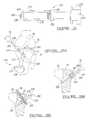
- the guide bushing 214includes a cylindrical bore 216 which mates and is concentric with a bore 218 defined by the cylindrical body 206 .
- the guide bushing 214is secured substantially perpendicular to the cylindrical body 206 by means of a weld or any other appropriate fixation.
- the guide bushing 214engages the opening of the tibial tunnel and is operable to permit a guide bore to be formed substantially perpendicular to the tibial tunnel, further discussed herein.
- the cylindrical body 206 of the counterbore guide 204is axially slid into the entrance opening 60 of the tibial tunnel 52 .
- the counterbore guide 204is slidably advanced into the tibial tunnel 52 until the positioning bar 212 engages and is flush against the medial cortex of the tibial 54 along two contact points. This will align the guide bushing 214 substantially adjacent and in contact with the anterior edge 64 or superior portion of the entrance opening 60 of the tibial tunnel 52 . This provides for a stable three point contact at the entrance opening 60 to the tibial tunnel 52 .
- the planar region 210 of the handle 208acts as a site mechanism with the guide bushing 214 to insure proper rotation of the counterbore guide 204 in the tibial tunnel 52 .
- the four bundle graft 78is first secured within the femoral tunnel 58 of the femur 56 using one of the many techniques known in the art and as previously described herein. Once the graft 78 is secured within the femoral tunnel 58 , the graft 78 extends out through the tibial tunnel 52 . The second portion 224 of the combination implant and guide instrument 220 is then threadably secured to the first portion 222 by way of the threaded sidewall 250 and the threaded connection member 236 . Once assembled, the shaft 232 extends out beyond the impact plate 244 by about 1.25 inches.
- the fixation apparatus 200is initially engaged with only the guide spikes 32 penetrating cancellous bone of the tibia 54 with the relief face 20 directed toward the entrance opening 60 .
- the four bundle graft 78is appropriately tensioned by pulling the four bundle graft 78 under the engagement spikes 36 within the counterbore 66 and out the area 102 defined by the relief 20 (see FIG. 5E) without binding on the sidewall 16 or the counterbore 66 .
- the apparatus 200is fully implanted or nested within the counterbore 66 by striking the handle 226 with a mallet or other appropriate driving device, as shown clearly in FIG. 22 C.
- the engagement spikes 36penetrate the two grafts 94 and 96 on the first side of the guide shaft 232 at multiple sights and the two grafts 98 and 100 on the second side of the guide shaft 232 to maintain the proper tensioning of the four bundle graft 78 .
- the combination implant and guide instrument 270threadably receives the apparatus 200 , via the threaded sidewall 202 and the threaded connector member 288 .
- the impact face 284nestingly seats within the counterbore 28 as the apparatus 200 threadably engages the threaded connector member 288 .
- the apparatus 200is again aligned substantially perpendicular to the tibial tunnel 52 by means of the guide wire 290 .
- the guide wire 290extends through the apparatus 200 and into the bore 278 of the instrument 270 so that the instrument 270 is slidably guided by the guide wire 290 substantially perpendicular to the tibial tunnel 52 .
Landscapes
- Health & Medical Sciences (AREA)
- Life Sciences & Earth Sciences (AREA)
- Orthopedic Medicine & Surgery (AREA)
- Surgery (AREA)
- Veterinary Medicine (AREA)
- Engineering & Computer Science (AREA)
- Biomedical Technology (AREA)
- Heart & Thoracic Surgery (AREA)
- Public Health (AREA)
- Rheumatology (AREA)
- Animal Behavior & Ethology (AREA)
- General Health & Medical Sciences (AREA)
- Oral & Maxillofacial Surgery (AREA)
- Molecular Biology (AREA)
- Medical Informatics (AREA)
- Nuclear Medicine, Radiotherapy & Molecular Imaging (AREA)
- Rehabilitation Therapy (AREA)
- Cardiology (AREA)
- Transplantation (AREA)
- Vascular Medicine (AREA)
- Dentistry (AREA)
- Surgical Instruments (AREA)
- Prostheses (AREA)
Abstract
Description
Claims (19)
Priority Applications (6)
| Application Number | Priority Date | Filing Date | Title |
|---|---|---|---|
| US10/167,074US6755840B2 (en) | 1997-07-23 | 2002-06-10 | Apparatus and method for tibial fixation of soft tissue |
| US10/874,915US7211111B2 (en) | 1997-07-23 | 2004-06-23 | Apparatus and method for tibial fixation of soft tissue |
| US11/742,009US8221498B2 (en) | 1997-07-23 | 2007-04-30 | Apparatus and method for tibial fixation of soft tissue |
| US13/242,143US9011534B2 (en) | 1997-07-23 | 2011-09-23 | Apparatus and method for tibial fixation of soft tissue |
| US13/549,912US8647385B2 (en) | 1997-07-23 | 2012-07-16 | Apparatus and method for tibial fixation of soft tissue |
| US14/689,338US20150320545A1 (en) | 1997-07-23 | 2015-04-17 | Apparatus And Method For Tibial Fixation Of Soft Tissue |
Applications Claiming Priority (4)
| Application Number | Priority Date | Filing Date | Title |
|---|---|---|---|
| US08/900,602US5931869A (en) | 1997-07-23 | 1997-07-23 | Apparatus and method for tibial fixation of soft tissue |
| US09/356,959US6280472B1 (en) | 1997-07-23 | 1999-07-19 | Apparatus and method for tibial fixation of soft tissue |
| US09/616,544US6482232B1 (en) | 1997-07-23 | 2000-07-14 | Apparatus and method for tibial fixation of soft tissue |
| US10/167,074US6755840B2 (en) | 1997-07-23 | 2002-06-10 | Apparatus and method for tibial fixation of soft tissue |
Related Parent Applications (1)
| Application Number | Title | Priority Date | Filing Date |
|---|---|---|---|
| US09/616,544DivisionUS6482232B1 (en) | 1997-07-23 | 2000-07-14 | Apparatus and method for tibial fixation of soft tissue |
Related Child Applications (1)
| Application Number | Title | Priority Date | Filing Date |
|---|---|---|---|
| US10/874,915DivisionUS7211111B2 (en) | 1997-07-23 | 2004-06-23 | Apparatus and method for tibial fixation of soft tissue |
Publications (2)
| Publication Number | Publication Date |
|---|---|
| US20030009218A1 US20030009218A1 (en) | 2003-01-09 |
| US6755840B2true US6755840B2 (en) | 2004-06-29 |
Family
ID=23403688
Family Applications (8)
| Application Number | Title | Priority Date | Filing Date |
|---|---|---|---|
| US09/356,959Expired - LifetimeUS6280472B1 (en) | 1997-07-23 | 1999-07-19 | Apparatus and method for tibial fixation of soft tissue |
| US09/616,544Expired - LifetimeUS6482232B1 (en) | 1997-07-23 | 2000-07-14 | Apparatus and method for tibial fixation of soft tissue |
| US10/167,074Expired - LifetimeUS6755840B2 (en) | 1997-07-23 | 2002-06-10 | Apparatus and method for tibial fixation of soft tissue |
| US10/874,915Expired - LifetimeUS7211111B2 (en) | 1997-07-23 | 2004-06-23 | Apparatus and method for tibial fixation of soft tissue |
| US11/742,009Expired - Fee RelatedUS8221498B2 (en) | 1997-07-23 | 2007-04-30 | Apparatus and method for tibial fixation of soft tissue |
| US13/242,143Expired - Fee RelatedUS9011534B2 (en) | 1997-07-23 | 2011-09-23 | Apparatus and method for tibial fixation of soft tissue |
| US13/549,912Expired - Fee RelatedUS8647385B2 (en) | 1997-07-23 | 2012-07-16 | Apparatus and method for tibial fixation of soft tissue |
| US14/689,338AbandonedUS20150320545A1 (en) | 1997-07-23 | 2015-04-17 | Apparatus And Method For Tibial Fixation Of Soft Tissue |
Family Applications Before (2)
| Application Number | Title | Priority Date | Filing Date |
|---|---|---|---|
| US09/356,959Expired - LifetimeUS6280472B1 (en) | 1997-07-23 | 1999-07-19 | Apparatus and method for tibial fixation of soft tissue |
| US09/616,544Expired - LifetimeUS6482232B1 (en) | 1997-07-23 | 2000-07-14 | Apparatus and method for tibial fixation of soft tissue |
Family Applications After (5)
| Application Number | Title | Priority Date | Filing Date |
|---|---|---|---|
| US10/874,915Expired - LifetimeUS7211111B2 (en) | 1997-07-23 | 2004-06-23 | Apparatus and method for tibial fixation of soft tissue |
| US11/742,009Expired - Fee RelatedUS8221498B2 (en) | 1997-07-23 | 2007-04-30 | Apparatus and method for tibial fixation of soft tissue |
| US13/242,143Expired - Fee RelatedUS9011534B2 (en) | 1997-07-23 | 2011-09-23 | Apparatus and method for tibial fixation of soft tissue |
| US13/549,912Expired - Fee RelatedUS8647385B2 (en) | 1997-07-23 | 2012-07-16 | Apparatus and method for tibial fixation of soft tissue |
| US14/689,338AbandonedUS20150320545A1 (en) | 1997-07-23 | 2015-04-17 | Apparatus And Method For Tibial Fixation Of Soft Tissue |
Country Status (4)
| Country | Link |
|---|---|
| US (8) | US6280472B1 (en) |
| EP (1) | EP1070482B1 (en) |
| AT (1) | ATE343353T1 (en) |
| DE (1) | DE60031482T2 (en) |
Cited By (13)
| Publication number | Priority date | Publication date | Assignee | Title |
|---|---|---|---|---|
| US20030114865A1 (en)* | 2001-12-19 | 2003-06-19 | Sater Ghaleb A. | Surgical anchor implantation device |
| US20050149187A1 (en)* | 2000-08-28 | 2005-07-07 | Ron Clark | Method and implant for securing ligament replacement into the knee |
| US20050273003A1 (en)* | 2003-10-15 | 2005-12-08 | Arthrotek, Inc. | Method and apparatus for graft fixation |
| US20070015953A1 (en)* | 2005-07-13 | 2007-01-18 | Boston Scientific Scimed, Inc. | Snap fit sling anchor system and related methods |
| US20070239166A1 (en)* | 2004-05-11 | 2007-10-11 | Mcguire David A | Surgical Device for Anterolateral and Posterolateral Reconstruction |
| US20080177386A1 (en)* | 2006-10-17 | 2008-07-24 | Arthroscopic Innovations Llc | Method and apparatus for surgical repair |
| US20080228271A1 (en)* | 2007-03-13 | 2008-09-18 | Biomet Sports Medicine, Inc. | Method and apparatus for graft fixation |
| US20080243248A1 (en)* | 2007-03-30 | 2008-10-02 | Biomet Sports Medicine, Inc. | In situ graft preparation for knee ligament reconstruction |
| US7749226B2 (en) | 2006-09-22 | 2010-07-06 | Biomet Sports Medicine, Llc | Method for forming a tunnel in a bone |
| US8002778B1 (en)* | 2004-06-28 | 2011-08-23 | Biomet Sports Medicine, Llc | Crosspin and method for inserting the same during soft ligament repair |
| US8647385B2 (en) | 1997-07-23 | 2014-02-11 | Biomet Sports Medicine, Llc | Apparatus and method for tibial fixation of soft tissue |
| US9333069B2 (en) | 2011-10-14 | 2016-05-10 | Biomet Sports Medicine, Llc | Method and apparatus for attaching soft tissue to bone |
| US10828146B2 (en) | 2016-08-04 | 2020-11-10 | Stryker Corporation | Instrumentation for soft tissue reconstruction |
Families Citing this family (93)
| Publication number | Priority date | Publication date | Assignee | Title |
|---|---|---|---|---|
| US6752830B1 (en)* | 1999-07-20 | 2004-06-22 | Ethicon, Inc. | Apparatus and method for reconstructing a ligament |
| AU2001251700A1 (en)* | 2000-02-23 | 2001-09-03 | Ethicon Inc. | Apparatus and method for reconstructing a ligament |
| AU5326701A (en) | 2000-04-05 | 2001-10-23 | Kyphon Inc | Methods and devices for treating fractured and/or diseased bone |
| US6485503B2 (en)* | 2000-05-19 | 2002-11-26 | Coapt Systems, Inc. | Multi-point tissue tension distribution device, a brow and face lift variation, and a method of tissue approximation using the device |
| US20050119694A1 (en)* | 2000-05-19 | 2005-06-02 | Jacobs Daniel I. | Remotely anchored tissue fixation device and method |
| US7156862B2 (en)* | 2000-05-19 | 2007-01-02 | Coapt Systems, Inc. | Multi-point tension distribution system device and method of tissue approximation using that device to improve wound healing |
| US6645226B1 (en)* | 2000-05-19 | 2003-11-11 | Coapt Systems, Inc. | Multi-point tension distribution system device and method of tissue approximation using that device to improve wound healing |
| US7510566B2 (en)* | 2000-05-19 | 2009-03-31 | Coapt Systems, Inc. | Multi-point tissue tension distribution device and method, a chin lift variation |
| US7172615B2 (en)* | 2000-05-19 | 2007-02-06 | Coapt Systems, Inc. | Remotely anchored tissue fixation device |
| US6869390B2 (en)* | 2000-06-05 | 2005-03-22 | Mentor Corporation | Automated implantation system for radioisotope seeds |
| DE10104658A1 (en)* | 2001-02-02 | 2002-10-02 | Aesculap Ag & Co Kg | Implant for fixing a tendoplasty in a channel in the knee region of the tibia and/or femur comprises fixing the tendoplasty under tension in the channel by relative movement between a bearing element and a connecting element |
| US7195642B2 (en) | 2001-03-13 | 2007-03-27 | Mckernan Daniel J | Method and apparatus for fixing a graft in a bone tunnel |
| US7594917B2 (en)* | 2001-03-13 | 2009-09-29 | Ethicon, Inc. | Method and apparatus for fixing a graft in a bone tunnel |
| US6517546B2 (en)* | 2001-03-13 | 2003-02-11 | Gregory R. Whittaker | Method and apparatus for fixing a graft in a bone tunnel |
| GB0107708D0 (en)* | 2001-03-28 | 2001-05-16 | Imp College Innovations Ltd | Bone fixated,articulated joint load control device |
| US20040153153A1 (en)* | 2001-05-31 | 2004-08-05 | Elson Robert J. | Anterior cruciate ligament reconstruction system and method of implementing same |
| US20050065533A1 (en)* | 2001-05-31 | 2005-03-24 | Magen Hugh E. | Apparatus for assembling anterior cruciate ligament reconstruction system |
| US20030142676A1 (en)* | 2002-01-25 | 2003-07-31 | Raymond Zeisz | Method and apparauts for admission control in packet switch |
| US7255700B2 (en)* | 2003-06-18 | 2007-08-14 | Biomet Sports Medicine, Inc. | Device and method of fastening a graft to a bone |
| US7300439B2 (en)* | 2003-06-24 | 2007-11-27 | Depuy Mitek, Inc. | Porous resorbable graft fixation pin |
| WO2005016155A1 (en)* | 2003-08-13 | 2005-02-24 | Synthes Gmbh | Curved positioning and insertion instrument for inserting a guide wire into the femur |
| US7481832B1 (en) | 2003-09-09 | 2009-01-27 | Biomet Sports Medicine, Llc | Method and apparatus for use of a self-tapping resorbable screw |
| US20050197699A1 (en)* | 2004-02-10 | 2005-09-08 | Jacobs Daniel I. | Tissue repair apparatus and method |
| US9474560B2 (en) | 2004-04-08 | 2016-10-25 | Globus Medical, Inc | Load distribution crown |
| US7615069B2 (en)* | 2004-04-08 | 2009-11-10 | Globus Medical, Inc. | Load distribution crown |
| US7468074B2 (en)* | 2004-10-29 | 2008-12-23 | Arthrex, Inc. | Ligament fixation using graft harness |
| US7371260B2 (en)* | 2005-10-26 | 2008-05-13 | Biomet Sports Medicine, Inc. | Method and instrumentation for the preparation and transplantation of osteochondral allografts |
| US20110160766A1 (en)* | 2005-11-02 | 2011-06-30 | Hendren Ronald D | Medical Affixation Device |
| US20070276506A1 (en)* | 2006-05-25 | 2007-11-29 | Biomet Manufacturing Corp. | Demineralized osteochondral plug |
| GR20060100566A (en)* | 2006-10-12 | 2008-05-21 | Γεωργιος Στεφανουδακης | Tendon grafts securing device. |
| US8409281B2 (en) | 2007-05-01 | 2013-04-02 | Moximed, Inc. | Adjustable absorber designs for implantable device |
| US8894714B2 (en) | 2007-05-01 | 2014-11-25 | Moximed, Inc. | Unlinked implantable knee unloading device |
| US8709090B2 (en) | 2007-05-01 | 2014-04-29 | Moximed, Inc. | Adjustable absorber designs for implantable device |
| US9907645B2 (en) | 2007-05-01 | 2018-03-06 | Moximed, Inc. | Adjustable absorber designs for implantable device |
| US8123805B2 (en) | 2007-05-01 | 2012-02-28 | Moximed, Inc. | Adjustable absorber designs for implantable device |
| US10022154B2 (en) | 2007-05-01 | 2018-07-17 | Moximed, Inc. | Femoral and tibial base components |
| US20110245928A1 (en) | 2010-04-06 | 2011-10-06 | Moximed, Inc. | Femoral and Tibial Bases |
| US7655041B2 (en) | 2007-05-01 | 2010-02-02 | Moximed, Inc. | Extra-articular implantable mechanical energy absorbing systems and implantation method |
| US20080275567A1 (en)* | 2007-05-01 | 2008-11-06 | Exploramed Nc4, Inc. | Extra-Articular Implantable Mechanical Energy Absorbing Systems |
| US20100137996A1 (en)* | 2007-05-01 | 2010-06-03 | Moximed, Inc. | Femoral and tibial base components |
| EP1987779B1 (en) | 2007-05-02 | 2016-04-13 | Arthrex, Inc. | Suture tensioning device |
| US8177849B2 (en) | 2007-05-07 | 2012-05-15 | Zimmer, Inc. | Methods and apparatuses for attaching tissue to orthopaedic implants |
| US20090149884A1 (en)* | 2007-08-02 | 2009-06-11 | Redyns Medical, Llc | System and method for bridge anchor tendon attachment |
| US8894651B2 (en)* | 2007-09-11 | 2014-11-25 | Kamran Aflatoon | Method of lateral facet approach, decompression and fusion using screws and staples as well as arthroplasty |
| US8303592B2 (en)* | 2007-10-05 | 2012-11-06 | Biomet Manufacturing Corp. | System for forming a tendon-bone graft |
| US8322256B2 (en)* | 2007-10-05 | 2012-12-04 | Biomet Manufacturing Corp. | System for forming a tendon-bone graft |
| US9826992B2 (en) | 2007-12-21 | 2017-11-28 | Smith & Nephew, Inc. | Multiple portal guide |
| US8298239B2 (en)* | 2008-02-21 | 2012-10-30 | Tyco Healthcare Group Lp | Tibial guide for ACL repair having interchangeable and/or rotatable outrigger |
| US8323289B2 (en)* | 2008-02-21 | 2012-12-04 | Covidien Lp | Tibial guide for ACL repair having left/right docking configuration |
| US20100049199A1 (en)* | 2008-02-21 | 2010-02-25 | Tyco Healthcare Group Lp | Tibial guide for acl repair having moveable distal features |
| US20100049198A1 (en)* | 2008-02-21 | 2010-02-25 | Tyco Healthcare Group Lp | Tibial guide for acl repair having off-axis guide wire arrangement |
| US20090264924A1 (en)* | 2008-04-19 | 2009-10-22 | James Ushiba | Surgical device and method |
| US8535377B2 (en)* | 2009-03-31 | 2013-09-17 | Imds Corporation | Double bundle ACL repair system |
| CN102481187B (en)* | 2009-03-31 | 2016-06-08 | 医学嵌入公司暨Imds共同创新公司 | Double bundle acl is repaired |
| JP5306900B2 (en)* | 2009-05-19 | 2013-10-02 | メイラ株式会社 | Transplanted tendon anchor with bone fragment for ligament reconstruction |
| CA2771332C (en) | 2009-08-27 | 2020-11-10 | Cotera, Inc. | Method and apparatus for force redistribution in articular joints |
| US9668868B2 (en) | 2009-08-27 | 2017-06-06 | Cotera, Inc. | Apparatus and methods for treatment of patellofemoral conditions |
| US9278004B2 (en) | 2009-08-27 | 2016-03-08 | Cotera, Inc. | Method and apparatus for altering biomechanics of the articular joints |
| US10349980B2 (en) | 2009-08-27 | 2019-07-16 | The Foundry, Llc | Method and apparatus for altering biomechanics of the shoulder |
| US9861408B2 (en) | 2009-08-27 | 2018-01-09 | The Foundry, Llc | Method and apparatus for treating canine cruciate ligament disease |
| MX2013003496A (en) | 2010-09-27 | 2013-12-02 | Smith & Nephew Inc | Device and methods for use during arthroscopic surgery. |
| US8617168B2 (en) | 2010-10-25 | 2013-12-31 | Smith & Nephew, Inc. | Oval tibia guide |
| WO2012061639A1 (en) | 2010-11-03 | 2012-05-10 | Smith & Nephew, Inc. | Drill guide |
| US9044270B2 (en) | 2011-03-29 | 2015-06-02 | Moximed, Inc. | Apparatus for controlling a load on a hip joint |
| US8617176B2 (en) | 2011-08-24 | 2013-12-31 | Depuy Mitek, Llc | Cross pinning guide devices and methods |
| US8968402B2 (en) | 2011-10-18 | 2015-03-03 | Arthrocare Corporation | ACL implants, instruments, and methods |
| US9468466B1 (en) | 2012-08-24 | 2016-10-18 | Cotera, Inc. | Method and apparatus for altering biomechanics of the spine |
| US9277939B2 (en)* | 2012-09-28 | 2016-03-08 | Warsaw Orthopedic, Inc. | Spinal correction system and method |
| US9265547B2 (en) | 2012-11-14 | 2016-02-23 | Tipirneni Software Llc | Orthopedic bonding agent application tool |
| US8979940B2 (en)* | 2012-12-14 | 2015-03-17 | Biomet Manufacturing, Llc | Modular attachment mechanism in prosthetic implants |
| US9265600B2 (en) | 2013-02-27 | 2016-02-23 | Orthopediatrics Corp. | Graft fixation |
| US9968373B1 (en)* | 2014-02-21 | 2018-05-15 | Surgentec, Llc | Handles for needle assemblies |
| US10034742B2 (en) | 2014-10-23 | 2018-07-31 | Medos International Sarl | Biceps tenodesis implants and delivery tools |
| US10856966B2 (en) | 2014-10-23 | 2020-12-08 | Medos International Sarl | Biceps tenodesis implants and delivery tools |
| US10729419B2 (en) | 2014-10-23 | 2020-08-04 | Medos International Sarl | Biceps tenodesis implants and delivery tools |
| US10076374B2 (en) | 2014-10-23 | 2018-09-18 | Medos International Sárl | Biceps tenodesis delivery tools |
| US10751161B2 (en) | 2014-10-23 | 2020-08-25 | Medos International Sárl | Biceps tenodesis anchor implants |
| USD851250S1 (en)* | 2015-11-19 | 2019-06-11 | Orthovestments, Llc | Bone staple |
| US20200383684A1 (en)* | 2015-02-24 | 2020-12-10 | Orthovestments, Llc | Orthopedic bone staple with polyaxial compression capability |
| US9649108B2 (en)* | 2015-02-24 | 2017-05-16 | Orthovestments, Llc | Orthopedic bone staple with polyaxial compression capability |
| US9693856B2 (en) | 2015-04-22 | 2017-07-04 | DePuy Synthes Products, LLC | Biceps repair device |
| US10231823B2 (en) | 2016-04-08 | 2019-03-19 | Medos International Sarl | Tenodesis implants and tools |
| US10231824B2 (en) | 2016-04-08 | 2019-03-19 | Medos International Sárl | Tenodesis anchoring systems and tools |
| US10251744B2 (en) | 2017-01-27 | 2019-04-09 | Onkos Surgical, Inc. | Soft tissue fixation device |
| US12279946B2 (en) | 2017-07-31 | 2025-04-22 | Loria Hair Implant Company Llc | Hair implants comprising enhanced anchoring and medical safety features |
| US11564789B2 (en) | 2017-07-31 | 2023-01-31 | Loria Products Llc | Hair implants comprising enhanced anchoring and medical safety features |
| MX2020001324A (en) | 2017-07-31 | 2020-10-28 | Loria Products Llc | Hair implants comprising enhanced anchoring and medical safety features. |
| US10407602B2 (en)* | 2017-11-30 | 2019-09-10 | Trane International Inc. | Low global warming potential refrigerants in liquid chillers |
| US11000360B2 (en) | 2018-09-14 | 2021-05-11 | Onkos Surgical, Inc. | Systems and methods for attaching soft tissue to an implant |
| EP3669825A1 (en)* | 2018-12-19 | 2020-06-24 | Abanza Tecnomed, S.L. | Medical fastening device for the fastening of grafts |
| WO2021019413A1 (en)* | 2019-07-30 | 2021-02-04 | Stefan Eggli | Bone bridge drill guide |
| USD917050S1 (en)* | 2019-08-26 | 2021-04-20 | Loria Products Llc | Hair implant |
| US12390217B2 (en)* | 2022-09-12 | 2025-08-19 | Marc F Matarazzo | Bicep tenodesis arthroscopic staple |
Citations (55)
| Publication number | Priority date | Publication date | Assignee | Title |
|---|---|---|---|---|
| US2248054A (en)* | 1939-06-07 | 1941-07-08 | Becker Joseph | Screw driver |
| US2267925A (en)* | 1941-02-11 | 1941-12-30 | Herbert A Johnston | Fracture securing apparatus |
| US2570465A (en)* | 1949-08-01 | 1951-10-09 | Joseph S Lundholm | Means for fixation of hip fractures |
| US3208450A (en)* | 1962-03-14 | 1965-09-28 | Abelson Louis | Fracture setting tool |
| US4278091A (en) | 1980-02-01 | 1981-07-14 | Howmedica, Inc. | Soft tissue retainer for use with bone implants, especially bone staples |
| EP0042657A1 (en) | 1980-06-19 | 1981-12-30 | Rylands-Whitecross Limited | Improvements in or relating to nails |
| US4341206A (en) | 1978-12-19 | 1982-07-27 | Synthes Ag | Device for producing a hole in a bone |
| US4522202A (en) | 1981-01-12 | 1985-06-11 | Schwarzkopf Development Corporation | Curved intramedullary lower leg spike |
| US4592346A (en) | 1985-04-08 | 1986-06-03 | Jurgutis John A | Orthopedic staple |
| US4605414A (en) | 1984-06-06 | 1986-08-12 | John Czajka | Reconstruction of a cruciate ligament |
| US4744793A (en) | 1985-09-06 | 1988-05-17 | Zimmer, Inc. | Prosthetic ligament connection assembly |
| US4755183A (en) | 1987-02-09 | 1988-07-05 | Pfizer Hospital Products Group, Inc. | Ligament prosthesis |
| US4793335A (en) | 1986-01-28 | 1988-12-27 | Sulzer Brothers Limited | Bone implant for fixing artificial tendons or ligaments with application and extraction means |
| US4828562A (en) | 1988-02-04 | 1989-05-09 | Pfizer Hospital Products Group, Inc. | Anterior cruciate ligament prosthesis |
| EP0358372A1 (en) | 1988-08-23 | 1990-03-14 | E. Marlowe Goble | Channel ligament clamp and system |
| US4950270A (en) | 1989-02-03 | 1990-08-21 | Boehringer Mannheim Corporation | Cannulated self-tapping bone screw |
| US4988351A (en) | 1989-01-06 | 1991-01-29 | Concept, Inc. | Washer for use with cancellous screw for attaching soft tissue to bone |
| US5013316A (en) | 1990-03-26 | 1991-05-07 | Marlowe Goble E | Soft tissue anchor system |
| US5024669A (en) | 1988-09-09 | 1991-06-18 | Baxter International Inc. | Artificial ligament of differential weave structure |
| US5047034A (en)* | 1990-05-29 | 1991-09-10 | Ace Orthopedic Manufacturing | Intramedullary rod screw guide |
| US5047032A (en)* | 1987-10-21 | 1991-09-10 | Richards Medical Company | Method and apparatus for cutting joint surfaces |
| US5062843A (en) | 1990-02-07 | 1991-11-05 | Mahony Iii Thomas H | Interference fixation screw with integral instrumentation |
| US5108397A (en) | 1990-04-19 | 1992-04-28 | Joseph White | Method and apparatus for stabilization of pelvic fractures |
| US5108431A (en) | 1990-07-06 | 1992-04-28 | Sulzer Brothers Limited | Ligament anchor |
| US5112335A (en) | 1989-07-11 | 1992-05-12 | Laboureau Jacques Philippe | Instrument for marking and drilling femoral and tibial insertion tunnels |
| US5152765A (en)* | 1989-09-08 | 1992-10-06 | Linvatec Corporation | Inserter for engaging tissue to be oriented adjacent bone |
| US5211647A (en) | 1992-02-19 | 1993-05-18 | Arthrex Inc. | Interference screw and cannulated sheath for endosteal fixation of ligaments |
| US5234434A (en) | 1992-08-17 | 1993-08-10 | Marlowe Goble E | Mutliple guide sleeve drill guide |
| FR2702646A1 (en) | 1993-03-18 | 1994-09-23 | Surgitec International Ltd | Improved ligament staple. |
| EP0409364B1 (en) | 1989-07-13 | 1994-09-28 | ARTOS Medizinische Produkte GmbH | Junction element for osteosynthesis |
| US5354300A (en)* | 1993-01-15 | 1994-10-11 | Depuy Inc. | Drill guide apparatus for installing a transverse pin |
| US5356435A (en) | 1991-05-13 | 1994-10-18 | Cendis Medical | Element for fixing ligaments |
| US5376119A (en) | 1992-11-02 | 1994-12-27 | Protek Ag | Attachment for an artificial ligament, and a process for implantation |
| EP0630613A2 (en) | 1993-06-21 | 1994-12-28 | United States Surgical Corporation | Orthopedic fastener applicator |
| US5385567A (en)* | 1990-09-07 | 1995-01-31 | Goble; E. Marlowe | Sight barrel arthroscopic instrument |
| US5393302A (en) | 1992-10-05 | 1995-02-28 | Clark; Ron | Process for endosteal ligament mounting |
| USRE34871E (en) | 1989-05-15 | 1995-03-07 | Mcguire; David A. | Process of endosteal fixation of a ligament |
| US5425767A (en) | 1992-11-02 | 1995-06-20 | Sulzer Medizinaltechnik Ag | Anchor for an artificial ligament |
| US5431651A (en) | 1993-02-08 | 1995-07-11 | Goble; E. Marlowe | Cross pin and set screw femoral and tibial fixation method |
| US5454811A (en) | 1993-11-08 | 1995-10-03 | Smith & Nephew Dyonics, Inc. | Cam lock orthopedic fixation screw and method |
| US5456685A (en) | 1994-02-14 | 1995-10-10 | Smith & Nephew Dyonics, Inc. | Interference screw having a tapered back root |
| USD374287S (en) | 1995-12-12 | 1996-10-01 | Zimmer, Inc. | Orthopadeic washer |
| USD374286S (en) | 1995-12-12 | 1996-10-01 | Zimmer, Inc. | Orthopaedic washer |
| USD374482S (en) | 1995-12-12 | 1996-10-08 | Zimmer, Inc. | Orthopaedic washer |
| USD375791S (en) | 1995-12-12 | 1996-11-19 | Zimmer, Inc. | Orthopaedic washer |
| US5575819A (en) | 1986-09-19 | 1996-11-19 | Imperial College Of Science And Technology | Artificial ligaments |
| US5741266A (en)* | 1996-09-19 | 1998-04-21 | Biomet, Inc. | Pin placement guide and method of making a bone entry hole for implantation of an intramedullary nail |
| WO1998022047A1 (en) | 1996-11-15 | 1998-05-28 | Medisolve Ltd. | Bone implant |
| EP0893109A2 (en) | 1997-07-23 | 1999-01-27 | Arthrotek, Inc. | Apparatus and method for tibial fixation of soft tissue |
| US5891150A (en)* | 1996-12-04 | 1999-04-06 | Chan; Kwan-Ho | Apparatus and method for fixing a ligament in a bone tunnel |
| US5931869A (en) | 1997-07-23 | 1999-08-03 | Arthrotek, Inc. | Apparatus and method for tibial fixation of soft tissue |
| US6077267A (en) | 1992-04-28 | 2000-06-20 | Huene; Donald R. | Absorbable bone screw and tool for its insertion |
| US6132433A (en)* | 1997-02-12 | 2000-10-17 | Arthrex, Inc. | Apparatus of loading tendons into the knee |
| US6254605B1 (en)* | 1990-07-16 | 2001-07-03 | Stephen M. Howell | Tibial guide |
| US6436100B1 (en)* | 1998-08-07 | 2002-08-20 | J. Lee Berger | Cannulated internally threaded bone screw and reduction driver device |
Family Cites Families (38)
| Publication number | Priority date | Publication date | Assignee | Title |
|---|---|---|---|---|
| US2420057A (en)* | 1943-05-13 | 1947-05-06 | Super Tool Company | Inserted blade cutter and clamping means |
| US2570464A (en)* | 1949-08-24 | 1951-10-09 | Trubenizing Process Corp | Sewing machine presser foot |
| US2702646A (en)* | 1952-09-26 | 1955-02-22 | William L Van Doren | Box handling truck |
| FR2165159A5 (en)* | 1971-12-21 | 1973-08-03 | Talan Maryan | |
| US4606414A (en)* | 1982-03-04 | 1986-08-19 | Institut Gornogo Dela Sibirskogo Otdelenia Akademii Nauk Sssr | Percussive air tool |
| US4828582A (en)* | 1983-08-29 | 1989-05-09 | General Electric Company | Polycrystalline abrasive grit |
| US4793355A (en) | 1987-04-17 | 1988-12-27 | Biomagnetic Technologies, Inc. | Apparatus for process for making biomagnetic measurements |
| US5334470A (en)* | 1991-09-02 | 1994-08-02 | Ricoh Company, Ltd. | Electrophotographic element with M-phenylenediamine derivatives therein |
| SE501621C2 (en)* | 1992-06-22 | 1995-03-27 | Volvo Penta Ab | Boat propeller drive with combined control, trim and tipping device |
| US5306301A (en)* | 1993-02-11 | 1994-04-26 | American Cyanamid Company | Graft attachment device and method of using same |
| US5632748A (en)* | 1993-06-14 | 1997-05-27 | Linvatec Corporation | Endosteal anchoring device for urging a ligament against a bone surface |
| US5507750A (en) | 1993-09-16 | 1996-04-16 | Goble; E. Marlowe | Method and apparatus for tensioning grafts or ligaments |
| USD374288S (en)* | 1994-05-23 | 1996-10-01 | Frans Dequeker | Set of synthetic posterior masticatory denture teeth |
| US5671695A (en)* | 1994-07-28 | 1997-09-30 | Depuy Inc. | Replacement ligament graft passer and method |
| USD374462S (en)* | 1994-08-09 | 1996-10-08 | Tyler Victor C | Hangtag for a sports cap |
| US5674224A (en) | 1994-11-18 | 1997-10-07 | Howell; Stephen M. | Bone mulch screw assembly for endosteal fixation of soft tissue grafts and method for using same |
| DE4444510A1 (en)* | 1994-11-30 | 1996-06-05 | Guenter Prof Dr Med Lob | Fastener for osteosynthesis |
| US5782919A (en)* | 1995-03-27 | 1998-07-21 | Sdgi Holdings, Inc. | Interbody fusion device and method for restoration of normal spinal anatomy |
| FR2740324B1 (en)* | 1995-10-27 | 1997-12-26 | Bgci | LIGAMENTARY ANCHORING DEVICE |
| WO1997029706A1 (en)* | 1996-02-16 | 1997-08-21 | Smith & Nephew, Inc. | Graft anchor |
| US5755718A (en)* | 1996-06-04 | 1998-05-26 | Sklar; Joseph H. | Apparatus and method for reconstructing ligaments |
| WO1998017209A2 (en)* | 1996-10-23 | 1998-04-30 | Sdgi Holdings, Inc. | Spinal spacer |
| US6533816B2 (en)* | 1999-02-09 | 2003-03-18 | Joseph H. Sklar | Graft ligament anchor and method for attaching a graft ligament to a bone |
| US5899938A (en)* | 1996-11-27 | 1999-05-04 | Joseph H. Sklar | Graft ligament anchor and method for attaching a graft ligament to a bone |
| US6554862B2 (en)* | 1996-11-27 | 2003-04-29 | Ethicon, Inc. | Graft ligament anchor and method for attaching a graft ligament to a bone |
| US6280472B1 (en) | 1997-07-23 | 2001-08-28 | Arthrotek, Inc. | Apparatus and method for tibial fixation of soft tissue |
| DE19833792A1 (en) | 1998-07-21 | 2000-02-03 | Helke Lob | Device for setting an osteosynthetic fixation element |
| DE19835096A1 (en)* | 1998-07-25 | 2000-01-27 | Helke Lob | Fixing element for repairing bone fractures comprises widening element and longitudinal fixing member located in bores in bone fragments |
| US6132442A (en) | 1999-03-25 | 2000-10-17 | Smith & Nephew | Graft clamp |
| US6498189B1 (en)* | 1999-11-10 | 2002-12-24 | University Of New Mexico | Method for induction of L-selectin shedding |
| WO2001089422A1 (en)* | 2000-05-24 | 2001-11-29 | Sklar Joseph H | Method and apparatus for making a ligament repair using compressed tendons |
| US6547778B1 (en)* | 2000-07-21 | 2003-04-15 | Joseph H. Sklar | Graft ligament strand tensioner |
| US20030130735A1 (en) | 2002-01-09 | 2003-07-10 | Roger Rogalski | Graft device and methods of use |
| GB0219280D0 (en) | 2002-08-19 | 2002-09-25 | Finsbury Dev Ltd | Prosthesis |
| US7658741B2 (en) | 2005-06-16 | 2010-02-09 | Zimmer, Inc. | Multi-positionable cut guide |
| US8562647B2 (en) | 2006-09-29 | 2013-10-22 | Biomet Sports Medicine, Llc | Method and apparatus for securing soft tissue to bone |
| US8118868B2 (en) | 2008-04-22 | 2012-02-21 | Biomet Manufacturing Corp. | Method and apparatus for attaching soft tissue to an implant |
| US9333069B2 (en) | 2011-10-14 | 2016-05-10 | Biomet Sports Medicine, Llc | Method and apparatus for attaching soft tissue to bone |
- 1999
- 1999-07-19USUS09/356,959patent/US6280472B1/ennot_activeExpired - Lifetime
- 2000
- 2000-07-14USUS09/616,544patent/US6482232B1/ennot_activeExpired - Lifetime
- 2000-07-19DEDE2000631482patent/DE60031482T2/ennot_activeExpired - Lifetime
- 2000-07-19ATAT00306127Tpatent/ATE343353T1/ennot_activeIP Right Cessation
- 2000-07-19EPEP20000306127patent/EP1070482B1/ennot_activeExpired - Lifetime
- 2002
- 2002-06-10USUS10/167,074patent/US6755840B2/ennot_activeExpired - Lifetime
- 2004
- 2004-06-23USUS10/874,915patent/US7211111B2/ennot_activeExpired - Lifetime
- 2007
- 2007-04-30USUS11/742,009patent/US8221498B2/ennot_activeExpired - Fee Related
- 2011
- 2011-09-23USUS13/242,143patent/US9011534B2/ennot_activeExpired - Fee Related
- 2012
- 2012-07-16USUS13/549,912patent/US8647385B2/ennot_activeExpired - Fee Related
- 2015
- 2015-04-17USUS14/689,338patent/US20150320545A1/ennot_activeAbandoned
Patent Citations (57)
| Publication number | Priority date | Publication date | Assignee | Title |
|---|---|---|---|---|
| US2248054A (en)* | 1939-06-07 | 1941-07-08 | Becker Joseph | Screw driver |
| US2267925A (en)* | 1941-02-11 | 1941-12-30 | Herbert A Johnston | Fracture securing apparatus |
| US2570465A (en)* | 1949-08-01 | 1951-10-09 | Joseph S Lundholm | Means for fixation of hip fractures |
| US3208450A (en)* | 1962-03-14 | 1965-09-28 | Abelson Louis | Fracture setting tool |
| US4341206A (en) | 1978-12-19 | 1982-07-27 | Synthes Ag | Device for producing a hole in a bone |
| US4278091A (en) | 1980-02-01 | 1981-07-14 | Howmedica, Inc. | Soft tissue retainer for use with bone implants, especially bone staples |
| EP0042657A1 (en) | 1980-06-19 | 1981-12-30 | Rylands-Whitecross Limited | Improvements in or relating to nails |
| US4522202A (en) | 1981-01-12 | 1985-06-11 | Schwarzkopf Development Corporation | Curved intramedullary lower leg spike |
| US4605414A (en) | 1984-06-06 | 1986-08-12 | John Czajka | Reconstruction of a cruciate ligament |
| US4592346A (en) | 1985-04-08 | 1986-06-03 | Jurgutis John A | Orthopedic staple |
| US4744793A (en) | 1985-09-06 | 1988-05-17 | Zimmer, Inc. | Prosthetic ligament connection assembly |
| US4793335A (en) | 1986-01-28 | 1988-12-27 | Sulzer Brothers Limited | Bone implant for fixing artificial tendons or ligaments with application and extraction means |
| US5575819A (en) | 1986-09-19 | 1996-11-19 | Imperial College Of Science And Technology | Artificial ligaments |
| US4755183A (en) | 1987-02-09 | 1988-07-05 | Pfizer Hospital Products Group, Inc. | Ligament prosthesis |
| US5047032A (en)* | 1987-10-21 | 1991-09-10 | Richards Medical Company | Method and apparatus for cutting joint surfaces |
| US4828562A (en) | 1988-02-04 | 1989-05-09 | Pfizer Hospital Products Group, Inc. | Anterior cruciate ligament prosthesis |
| EP0330328A1 (en) | 1988-02-04 | 1989-08-30 | Pfizer Hospital Products Group, Inc. | Anterior cruciate ligament prosthesis |
| EP0358372A1 (en) | 1988-08-23 | 1990-03-14 | E. Marlowe Goble | Channel ligament clamp and system |
| US5024669A (en) | 1988-09-09 | 1991-06-18 | Baxter International Inc. | Artificial ligament of differential weave structure |
| US4988351A (en) | 1989-01-06 | 1991-01-29 | Concept, Inc. | Washer for use with cancellous screw for attaching soft tissue to bone |
| US4950270A (en) | 1989-02-03 | 1990-08-21 | Boehringer Mannheim Corporation | Cannulated self-tapping bone screw |
| USRE34871E (en) | 1989-05-15 | 1995-03-07 | Mcguire; David A. | Process of endosteal fixation of a ligament |
| US5112335A (en) | 1989-07-11 | 1992-05-12 | Laboureau Jacques Philippe | Instrument for marking and drilling femoral and tibial insertion tunnels |
| EP0409364B1 (en) | 1989-07-13 | 1994-09-28 | ARTOS Medizinische Produkte GmbH | Junction element for osteosynthesis |
| US5152765A (en)* | 1989-09-08 | 1992-10-06 | Linvatec Corporation | Inserter for engaging tissue to be oriented adjacent bone |
| US5062843A (en) | 1990-02-07 | 1991-11-05 | Mahony Iii Thomas H | Interference fixation screw with integral instrumentation |
| US5282802A (en) | 1990-02-07 | 1994-02-01 | Mahony Iii Thomas H | Method of securing a tendon graft with an interference fixation screw |
| US5013316A (en) | 1990-03-26 | 1991-05-07 | Marlowe Goble E | Soft tissue anchor system |
| US5108397A (en) | 1990-04-19 | 1992-04-28 | Joseph White | Method and apparatus for stabilization of pelvic fractures |
| US5047034A (en)* | 1990-05-29 | 1991-09-10 | Ace Orthopedic Manufacturing | Intramedullary rod screw guide |
| US5108431A (en) | 1990-07-06 | 1992-04-28 | Sulzer Brothers Limited | Ligament anchor |
| US6254605B1 (en)* | 1990-07-16 | 2001-07-03 | Stephen M. Howell | Tibial guide |
| US5385567A (en)* | 1990-09-07 | 1995-01-31 | Goble; E. Marlowe | Sight barrel arthroscopic instrument |
| US5356435A (en) | 1991-05-13 | 1994-10-18 | Cendis Medical | Element for fixing ligaments |
| US5211647A (en) | 1992-02-19 | 1993-05-18 | Arthrex Inc. | Interference screw and cannulated sheath for endosteal fixation of ligaments |
| US6077267A (en) | 1992-04-28 | 2000-06-20 | Huene; Donald R. | Absorbable bone screw and tool for its insertion |
| US5234434A (en) | 1992-08-17 | 1993-08-10 | Marlowe Goble E | Mutliple guide sleeve drill guide |
| US5393302A (en) | 1992-10-05 | 1995-02-28 | Clark; Ron | Process for endosteal ligament mounting |
| US5376119A (en) | 1992-11-02 | 1994-12-27 | Protek Ag | Attachment for an artificial ligament, and a process for implantation |
| US5425767A (en) | 1992-11-02 | 1995-06-20 | Sulzer Medizinaltechnik Ag | Anchor for an artificial ligament |
| US5354300A (en)* | 1993-01-15 | 1994-10-11 | Depuy Inc. | Drill guide apparatus for installing a transverse pin |
| US5431651A (en) | 1993-02-08 | 1995-07-11 | Goble; E. Marlowe | Cross pin and set screw femoral and tibial fixation method |
| FR2702646A1 (en) | 1993-03-18 | 1994-09-23 | Surgitec International Ltd | Improved ligament staple. |
| EP0630613A2 (en) | 1993-06-21 | 1994-12-28 | United States Surgical Corporation | Orthopedic fastener applicator |
| US5454811A (en) | 1993-11-08 | 1995-10-03 | Smith & Nephew Dyonics, Inc. | Cam lock orthopedic fixation screw and method |
| US5456685A (en) | 1994-02-14 | 1995-10-10 | Smith & Nephew Dyonics, Inc. | Interference screw having a tapered back root |
| USD374482S (en) | 1995-12-12 | 1996-10-08 | Zimmer, Inc. | Orthopaedic washer |
| USD375791S (en) | 1995-12-12 | 1996-11-19 | Zimmer, Inc. | Orthopaedic washer |
| USD374286S (en) | 1995-12-12 | 1996-10-01 | Zimmer, Inc. | Orthopaedic washer |
| USD374287S (en) | 1995-12-12 | 1996-10-01 | Zimmer, Inc. | Orthopadeic washer |
| US5741266A (en)* | 1996-09-19 | 1998-04-21 | Biomet, Inc. | Pin placement guide and method of making a bone entry hole for implantation of an intramedullary nail |
| WO1998022047A1 (en) | 1996-11-15 | 1998-05-28 | Medisolve Ltd. | Bone implant |
| US5891150A (en)* | 1996-12-04 | 1999-04-06 | Chan; Kwan-Ho | Apparatus and method for fixing a ligament in a bone tunnel |
| US6132433A (en)* | 1997-02-12 | 2000-10-17 | Arthrex, Inc. | Apparatus of loading tendons into the knee |
| EP0893109A2 (en) | 1997-07-23 | 1999-01-27 | Arthrotek, Inc. | Apparatus and method for tibial fixation of soft tissue |
| US5931869A (en) | 1997-07-23 | 1999-08-03 | Arthrotek, Inc. | Apparatus and method for tibial fixation of soft tissue |
| US6436100B1 (en)* | 1998-08-07 | 2002-08-20 | J. Lee Berger | Cannulated internally threaded bone screw and reduction driver device |
Non-Patent Citations (2)
| Title |
|---|
| "Bone Mulch Screw Technique," 1996, by Arthrotek, Inc. |
| Trauma Systems, 1990 by Biomet, Inc. |
Cited By (28)
| Publication number | Priority date | Publication date | Assignee | Title |
|---|---|---|---|---|
| US9011534B2 (en) | 1997-07-23 | 2015-04-21 | Biomet Sports Medicine, Llc | Apparatus and method for tibial fixation of soft tissue |
| US8647385B2 (en) | 1997-07-23 | 2014-02-11 | Biomet Sports Medicine, Llc | Apparatus and method for tibial fixation of soft tissue |
| US20050149187A1 (en)* | 2000-08-28 | 2005-07-07 | Ron Clark | Method and implant for securing ligament replacement into the knee |
| US7837718B2 (en) | 2000-08-28 | 2010-11-23 | Biomet Sports Medicine, Llc | Method and implant for securing ligament replacement into the knee |
| US6974462B2 (en)* | 2001-12-19 | 2005-12-13 | Boston Scientific Scimed, Inc. | Surgical anchor implantation device |
| US20030114865A1 (en)* | 2001-12-19 | 2003-06-19 | Sater Ghaleb A. | Surgical anchor implantation device |
| US8784489B2 (en) | 2003-10-15 | 2014-07-22 | Biomet Sports Medicine, Llc | Method and apparatus for graft fixation |
| US7896917B2 (en) | 2003-10-15 | 2011-03-01 | Biomet Sports Medicine, Llc | Method and apparatus for graft fixation |
| US20110153018A1 (en)* | 2003-10-15 | 2011-06-23 | Biomet Sports Medicine, Llc | Method and Apparatus for Graft Fixation |
| US20050273003A1 (en)* | 2003-10-15 | 2005-12-08 | Arthrotek, Inc. | Method and apparatus for graft fixation |
| US20070239166A1 (en)* | 2004-05-11 | 2007-10-11 | Mcguire David A | Surgical Device for Anterolateral and Posterolateral Reconstruction |
| US8002778B1 (en)* | 2004-06-28 | 2011-08-23 | Biomet Sports Medicine, Llc | Crosspin and method for inserting the same during soft ligament repair |
| US20070015953A1 (en)* | 2005-07-13 | 2007-01-18 | Boston Scientific Scimed, Inc. | Snap fit sling anchor system and related methods |
| US8043205B2 (en) | 2005-07-13 | 2011-10-25 | Boston Scientific Scimed, Inc. | Snap fit sling anchor system |
| US8197482B2 (en) | 2006-09-22 | 2012-06-12 | Biomet Sports Medicine, Llc | Apparatus for forming a tunnel in a bone |
| US20100268233A1 (en)* | 2006-09-22 | 2010-10-21 | Biomet Sports Medicine, Llc | Apparatus for Forming a Tunnel in a Bone |
| US7749226B2 (en) | 2006-09-22 | 2010-07-06 | Biomet Sports Medicine, Llc | Method for forming a tunnel in a bone |
| US7963983B2 (en) | 2006-10-17 | 2011-06-21 | Arthroscopic Innovations Llc | Fixation device for surgical repair |
| US7942914B2 (en) | 2006-10-17 | 2011-05-17 | Arthroscopic Innovations Llc | Method and apparatus for surgical repair |
| US20080177386A1 (en)* | 2006-10-17 | 2008-07-24 | Arthroscopic Innovations Llc | Method and apparatus for surgical repair |
| US20080177336A1 (en)* | 2006-10-17 | 2008-07-24 | Arthroscopic Innovations Llc | Fixation device for surgical repair |
| US8900301B2 (en) | 2007-03-13 | 2014-12-02 | Biomet Sports Medicine, Llc | Method and apparatus for graft fixation |
| US8147546B2 (en) | 2007-03-13 | 2012-04-03 | Biomet Sports Medicine, Llc | Method and apparatus for graft fixation |
| US20080228271A1 (en)* | 2007-03-13 | 2008-09-18 | Biomet Sports Medicine, Inc. | Method and apparatus for graft fixation |
| US7766964B2 (en) | 2007-03-30 | 2010-08-03 | Biomet Sports Medicine, Llc | In situ graft preparation for knee ligament reconstruction |
| US20080243248A1 (en)* | 2007-03-30 | 2008-10-02 | Biomet Sports Medicine, Inc. | In situ graft preparation for knee ligament reconstruction |
| US9333069B2 (en) | 2011-10-14 | 2016-05-10 | Biomet Sports Medicine, Llc | Method and apparatus for attaching soft tissue to bone |
| US10828146B2 (en) | 2016-08-04 | 2020-11-10 | Stryker Corporation | Instrumentation for soft tissue reconstruction |
Also Published As
| Publication number | Publication date |
|---|---|
| US20030009218A1 (en) | 2003-01-09 |
| US20120016474A1 (en) | 2012-01-19 |
| EP1070482A2 (en) | 2001-01-24 |
| US6280472B1 (en) | 2001-08-28 |
| EP1070482B1 (en) | 2006-10-25 |
| US8647385B2 (en) | 2014-02-11 |
| US20150320545A1 (en) | 2015-11-12 |
| DE60031482T2 (en) | 2007-03-29 |
| US7211111B2 (en) | 2007-05-01 |
| US20070203499A1 (en) | 2007-08-30 |
| US20120283832A1 (en) | 2012-11-08 |
| ATE343353T1 (en) | 2006-11-15 |
| DE60031482D1 (en) | 2006-12-07 |
| US8221498B2 (en) | 2012-07-17 |
| EP1070482A3 (en) | 2002-04-17 |
| US9011534B2 (en) | 2015-04-21 |
| US6482232B1 (en) | 2002-11-19 |
| US20040267318A1 (en) | 2004-12-30 |
Similar Documents
| Publication | Publication Date | Title |
|---|---|---|
| US6755840B2 (en) | Apparatus and method for tibial fixation of soft tissue | |
| US5931869A (en) | Apparatus and method for tibial fixation of soft tissue | |
| US5674224A (en) | Bone mulch screw assembly for endosteal fixation of soft tissue grafts and method for using same | |
| US9333069B2 (en) | Method and apparatus for attaching soft tissue to bone | |
| US7338492B2 (en) | Cross-pin graft fixation, instruments, and methods | |
| US8100969B2 (en) | Methods for anchoring autologous or artificial tendon grafts using first and second bone anchors | |
| US5895425A (en) | Bone implant | |
| US8382835B2 (en) | Apparatus and method for manipulating a flexible strand and soft tissue replacement during surgery | |
| US7713300B2 (en) | Apparatus and method for manipulating a flexible strand and soft tissue replacement during surgery | |
| US7931657B2 (en) | Apparatus and method for manipulating a flexible strand and soft tissue replacement during surgery | |
| US7901456B2 (en) | Expanding ligament graft fixation system method | |
| US7229448B2 (en) | Apparatus and method for attaching a graft ligament to a bone | |
| US8496705B2 (en) | Method of anchoring autologous or artificial tendon grafts in bone | |
| US20050033301A1 (en) | Cross-pin graft fixation, instruments, and methods | |
| AU8278198A (en) | Apparatus and methods for anchoring autologous or artificial tendon grafts in bone | |
| EP1510188B1 (en) | Apparatus for tibial fixation of soft tissue |
Legal Events
| Date | Code | Title | Description |
|---|---|---|---|
| STCF | Information on status: patent grant | Free format text:PATENTED CASE | |
| AS | Assignment | Owner name:ARTHROTEK, INC., INDIANA Free format text:ASSIGNMENT OF ASSIGNORS INTEREST;ASSIGNORS:BOUCHER, JAMES A.;HOWELL, STEPHEN M.;MARCINEK, JAMES;AND OTHERS;REEL/FRAME:018746/0501;SIGNING DATES FROM 19990914 TO 19990930 | |
| AS | Assignment | Owner name:BIOMET SPORTS MEDICINE, INC., INDIANA Free format text:CHANGE OF NAME;ASSIGNOR:ARTHROTEK, INC.;REEL/FRAME:018970/0685 Effective date:20061227 | |
| FPAY | Fee payment | Year of fee payment:4 | |
| AS | Assignment | Owner name:BANK OF AMERICA, N.A., AS ADMINISTRATIVE AGENT FOR Free format text:SECURITY AGREEMENT;ASSIGNORS:LVB ACQUISITION, INC.;BIOMET, INC.;REEL/FRAME:020362/0001 Effective date:20070925 | |
| AS | Assignment | Owner name:BIOMET SPORTS MEDICINE, LLC, INDIANA Free format text:CHANGE OF NAME;ASSIGNOR:BIOMET SPORTS MEDICINE, INC.;REEL/FRAME:021387/0441 Effective date:20080227 Owner name:BIOMET SPORTS MEDICINE, LLC,INDIANA Free format text:CHANGE OF NAME;ASSIGNOR:BIOMET SPORTS MEDICINE, INC.;REEL/FRAME:021387/0441 Effective date:20080227 | |
| FPAY | Fee payment | Year of fee payment:8 | |
| AS | Assignment | Owner name:BIOMET, INC., INDIANA Free format text:RELEASE OF SECURITY INTEREST IN PATENTS RECORDED AT REEL 020362/ FRAME 0001;ASSIGNOR:BANK OF AMERICA, N.A., AS ADMINISTRATIVE AGENT;REEL/FRAME:037155/0133 Effective date:20150624 Owner name:LVB ACQUISITION, INC., INDIANA Free format text:RELEASE OF SECURITY INTEREST IN PATENTS RECORDED AT REEL 020362/ FRAME 0001;ASSIGNOR:BANK OF AMERICA, N.A., AS ADMINISTRATIVE AGENT;REEL/FRAME:037155/0133 Effective date:20150624 | |
| FPAY | Fee payment | Year of fee payment:12 | |
| AS | Assignment | Owner name:BIOMET U.S. RECONSTRUCTION, LLC, INDIANA Free format text:ASSIGNMENT OF ASSIGNORS INTEREST;ASSIGNOR:BIOMET SPORTS MEDICINE, LLC;REEL/FRAME:045935/0497 Effective date:20171103 Owner name:BIOMET, INC., INDIANA Free format text:ASSIGNMENT OF ASSIGNORS INTEREST;ASSIGNOR:BIOMET U.S. RECONSTRUCTION, LLC;REEL/FRAME:045935/0557 Effective date:20171103 Owner name:ZB MANUFACTURING, LLC, INDIANA Free format text:ASSIGNMENT OF ASSIGNORS INTEREST;ASSIGNOR:BIOMET, INC.;REEL/FRAME:045935/0570 Effective date:20171103 Owner name:BIOMET MANUFACTURING, LLC, INDIANA Free format text:ASSIGNMENT OF ASSIGNORS INTEREST;ASSIGNOR:ZB MANUFACTURING, LLC;REEL/FRAME:045935/0673 Effective date:20171103 |