US6755552B2 - Conductive plate of a bulb assembly - Google Patents
Conductive plate of a bulb assemblyDownload PDFInfo
- Publication number
- US6755552B2 US6755552B2US10/127,712US12771202AUS6755552B2US 6755552 B2US6755552 B2US 6755552B2US 12771202 AUS12771202 AUS 12771202AUS 6755552 B2US6755552 B2US 6755552B2
- Authority
- US
- United States
- Prior art keywords
- conductive plate
- bulb
- conductive
- connector
- received
- Prior art date
- Legal status (The legal status is an assumption and is not a legal conclusion. Google has not performed a legal analysis and makes no representation as to the accuracy of the status listed.)
- Expired - Lifetime, expires
Links
Images


Classifications
- F—MECHANICAL ENGINEERING; LIGHTING; HEATING; WEAPONS; BLASTING
- F21—LIGHTING
- F21V—FUNCTIONAL FEATURES OR DETAILS OF LIGHTING DEVICES OR SYSTEMS THEREOF; STRUCTURAL COMBINATIONS OF LIGHTING DEVICES WITH OTHER ARTICLES, NOT OTHERWISE PROVIDED FOR
- F21V19/00—Fastening of light sources or lamp holders
- F21V19/0005—Fastening of light sources or lamp holders of sources having contact pins, wires or blades, e.g. pinch sealed lamp
- F—MECHANICAL ENGINEERING; LIGHTING; HEATING; WEAPONS; BLASTING
- F21—LIGHTING
- F21S—NON-PORTABLE LIGHTING DEVICES; SYSTEMS THEREOF; VEHICLE LIGHTING DEVICES SPECIALLY ADAPTED FOR VEHICLE EXTERIORS
- F21S4/00—Lighting devices or systems using a string or strip of light sources
- F21S4/10—Lighting devices or systems using a string or strip of light sources with light sources attached to loose electric cables, e.g. Christmas tree lights
- H—ELECTRICITY
- H01—ELECTRIC ELEMENTS
- H01R—ELECTRICALLY-CONDUCTIVE CONNECTIONS; STRUCTURAL ASSOCIATIONS OF A PLURALITY OF MUTUALLY-INSULATED ELECTRICAL CONNECTING ELEMENTS; COUPLING DEVICES; CURRENT COLLECTORS
- H01R33/00—Coupling devices specially adapted for supporting apparatus and having one part acting as a holder providing support and electrical connection via a counterpart which is structurally associated with the apparatus, e.g. lamp holders; Separate parts thereof
- H01R33/05—Two-pole devices
- H01R33/06—Two-pole devices with two current-carrying pins, blades or analogous contacts, having their axes parallel to each other
- H01R33/09—Two-pole devices with two current-carrying pins, blades or analogous contacts, having their axes parallel to each other for baseless lamp bulb
- Y—GENERAL TAGGING OF NEW TECHNOLOGICAL DEVELOPMENTS; GENERAL TAGGING OF CROSS-SECTIONAL TECHNOLOGIES SPANNING OVER SEVERAL SECTIONS OF THE IPC; TECHNICAL SUBJECTS COVERED BY FORMER USPC CROSS-REFERENCE ART COLLECTIONS [XRACs] AND DIGESTS
- Y10—TECHNICAL SUBJECTS COVERED BY FORMER USPC
- Y10S—TECHNICAL SUBJECTS COVERED BY FORMER USPC CROSS-REFERENCE ART COLLECTIONS [XRACs] AND DIGESTS
- Y10S362/00—Illumination
- Y10S362/806—Ornamental or decorative
Definitions
- a conventional bulb assembly of a lighting stringincludes a connector ( 1 ), a holder ( 2 ), and a bulb ( 3 ).
- Conductive plates ( 4 )are provided in the connector ( 1 ), such that the plates ( 4 ) can contact with conductive wires ( 31 ) of the bulb ( 3 ), when the bulb ( 3 ) and the holder ( 2 ) are assembled within the connector ( 1 ).
- This known conductive plate ( 4 )in order to provide effective elastic contact, is designed with an elastic plate ( 41 ), which is folded upside-down from the conductive plate ( 4 ) and is inclined. As assembly, the folded portion ( 42 ) between the conductive plate ( 4 ) and the elastic plate ( 41 ) will be easily broken under elastic compress. When the elastic plate ( 41 ) is fallen, it causes ineffective electrical contact between the conductive plate ( 4 ) and the conductive wire ( 31 ) of the bulb ( 3 ).
- the primary object of the inventionis to provide a conductive plate of a bulb assembly, which uses a part of the plate to be folded inward.
- the improved conductive plate with inward sliceobtains a strong strength for preventing from drawbacks of a prior one.
- FIG. 1is a cross-sectional plan view showing an exploded bulb assembly of a prior structure.
- FIG. 2is an assembled view of FIG. 1 .
- FIG. 3is a perspective view showing a conductive plate of FIG. 1 .
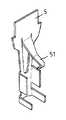
- FIG. 4is a perspective view showing a conductive plate according to the present invention.
- FIG. 5is a cross-sectional plan view showing an exploded bulb assembly according to the present invention.
- FIG. 6is an assembled view of FIG. 5 .
- the present inventionmainly relates to an improvement of a conductive plate ( 5 ) provided in a connector ( 1 ) of a bulb assembly.
- the conductive plate ( 5 )is formed with an inner elastic slice ( 51 ) from middle portion, which can be folded inward to be inclined directly, as shown in FIG. 4 .
- the elastic slice ( 51 )can effectively and elastically contact with conductive wire ( 31 ) of the bulb ( 3 ) respectively for obtaining electrical connection.
- the elastic slice ( 51 )is just bent inclinedly inward without a folded portion. And when assembly, the elastic slice ( 51 ) is forced outward that will not be any possibility in broken of the conductive plate and overcomes the drawback of a known design.
Landscapes
- Engineering & Computer Science (AREA)
- General Engineering & Computer Science (AREA)
- Connecting Device With Holders (AREA)
Abstract
Description
Referring to FIGS. 1 to3, a conventional bulb assembly of a lighting string includes a connector (1), a holder (2), and a bulb (3). Conductive plates (4) are provided in the connector (1), such that the plates (4) can contact with conductive wires (31) of the bulb (3), when the bulb (3) and the holder (2) are assembled within the connector (1). This known conductive plate (4), in order to provide effective elastic contact, is designed with an elastic plate (41), which is folded upside-down from the conductive plate (4) and is inclined. As assembly, the folded portion (42) between the conductive plate (4) and the elastic plate (41) will be easily broken under elastic compress. When the elastic plate (41) is fallen, it causes ineffective electrical contact between the conductive plate (4) and the conductive wire (31) of the bulb (3).
Accordingly, the primary object of the invention is to provide a conductive plate of a bulb assembly, which uses a part of the plate to be folded inward. The improved conductive plate with inward slice obtains a strong strength for preventing from drawbacks of a prior one. Now the features and advantages of the present invention will be described in detail with reference to the accompanying drawings.
FIG. 1 is a cross-sectional plan view showing an exploded bulb assembly of a prior structure.
FIG. 2 is an assembled view of FIG.1.
FIG. 3 is a perspective view showing a conductive plate of FIG.1.
FIG. 4 is a perspective view showing a conductive plate according to the present invention.
FIG. 5 is a cross-sectional plan view showing an exploded bulb assembly according to the present invention.
FIG. 6 is an assembled view of FIG.5.
Please refer to FIGS. 4 to6, the present invention mainly relates to an improvement of a conductive plate (5) provided in a connector (1) of a bulb assembly. The conductive plate (5) is formed with an inner elastic slice (51) from middle portion, which can be folded inward to be inclined directly, as shown in FIG.4. Thus, when a holder (2) with a bulb (3) is received in the connector (3), the elastic slice (51) can effectively and elastically contact with conductive wire (31) of the bulb (3) respectively for obtaining electrical connection.
Under the improved structure of this invention, the elastic slice (51) is just bent inclinedly inward without a folded portion. And when assembly, the elastic slice (51) is forced outward that will not be any possibility in broken of the conductive plate and overcomes the drawback of a known design.
Accordingly, the invented assembly of the present invention obviously obtains utility and improvement. It should be allowed for patent and is applied.
Claims (1)
1. A removable light bulb system comprising:
a hollow bulb connector defining a chamber therein;
a conductive plate being received within said chamber, said conductive plate having an opening formed therethrough and a conductive elastic spring element projecting from an upper edge of said opening, said opening having a contour conforming to a contour of said conductive elastic spring element; and,
a light bulb received by said hollow bulb connector, said light bulb having an electrically conductive portion, said electrically conductive portion being removably received within said chamber, said conductive elastic spring element of said conductive plate being adapted to be in freely releasable electrical contact with said electrically conductive portion of said light bulb.
Priority Applications (1)
| Application Number | Priority Date | Filing Date | Title |
|---|---|---|---|
| US10/127,712US6755552B2 (en) | 2002-04-23 | 2002-04-23 | Conductive plate of a bulb assembly |
Applications Claiming Priority (1)
| Application Number | Priority Date | Filing Date | Title |
|---|---|---|---|
| US10/127,712US6755552B2 (en) | 2002-04-23 | 2002-04-23 | Conductive plate of a bulb assembly |
Publications (2)
| Publication Number | Publication Date |
|---|---|
| US20030198044A1 US20030198044A1 (en) | 2003-10-23 |
| US6755552B2true US6755552B2 (en) | 2004-06-29 |
Family
ID=29215315
Family Applications (1)
| Application Number | Title | Priority Date | Filing Date |
|---|---|---|---|
| US10/127,712Expired - LifetimeUS6755552B2 (en) | 2002-04-23 | 2002-04-23 | Conductive plate of a bulb assembly |
Country Status (1)
| Country | Link |
|---|---|
| US (1) | US6755552B2 (en) |
Cited By (7)
| Publication number | Priority date | Publication date | Assignee | Title |
|---|---|---|---|---|
| US20060055870A1 (en)* | 2004-09-02 | 2006-03-16 | Greg Smith | Horizontally combinable eyewear assembly |
| US20070147094A1 (en)* | 2005-12-28 | 2007-06-28 | Hung-Wen Lee | Bulb assembly |
| US20080130284A1 (en)* | 2006-10-25 | 2008-06-05 | Altamura Steven J | Mechanical bypass light unit |
| US20090190359A1 (en)* | 2008-01-28 | 2009-07-30 | Cindex Holdings Limited (A Hong Kong Corporation) | Led light string system |
| US20090279325A1 (en)* | 2005-06-02 | 2009-11-12 | Gp Ltd. | Light string system |
| US20100099285A1 (en)* | 2008-10-20 | 2010-04-22 | Cindex Holdings Limited (A Hong Kong Corporation) | Light string system |
| US8235737B2 (en) | 2009-12-09 | 2012-08-07 | Polygroup Macau Limited (Bvi) | Light string system |
Families Citing this family (18)
| Publication number | Priority date | Publication date | Assignee | Title |
|---|---|---|---|---|
| US7943211B2 (en)* | 2007-12-06 | 2011-05-17 | Willis Electric Co., Ltd. | Three dimensional displays having deformable constructions |
| US20100289415A1 (en)* | 2009-05-18 | 2010-11-18 | Johnny Chen | Energy efficient decorative lighting |
| US20110085327A1 (en)* | 2009-10-14 | 2011-04-14 | Johnny Chen | Decorative light display with LEDs |
| US8568015B2 (en) | 2010-09-23 | 2013-10-29 | Willis Electric Co., Ltd. | Decorative light string for artificial lighted tree |
| US8298633B1 (en) | 2011-05-20 | 2012-10-30 | Willis Electric Co., Ltd. | Multi-positional, locking artificial tree trunk |
| US8569960B2 (en) | 2011-11-14 | 2013-10-29 | Willis Electric Co., Ltd | Conformal power adapter for lighted artificial tree |
| US9157587B2 (en) | 2011-11-14 | 2015-10-13 | Willis Electric Co., Ltd. | Conformal power adapter for lighted artificial tree |
| US8876321B2 (en) | 2011-12-09 | 2014-11-04 | Willis Electric Co., Ltd. | Modular lighted artificial tree |
| US10206530B2 (en) | 2012-05-08 | 2019-02-19 | Willis Electric Co., Ltd. | Modular tree with locking trunk |
| US9572446B2 (en) | 2012-05-08 | 2017-02-21 | Willis Electric Co., Ltd. | Modular tree with locking trunk and locking electrical connectors |
| US9179793B2 (en) | 2012-05-08 | 2015-11-10 | Willis Electric Co., Ltd. | Modular tree with rotation-lock electrical connectors |
| US9044056B2 (en) | 2012-05-08 | 2015-06-02 | Willis Electric Co., Ltd. | Modular tree with electrical connector |
| US9439528B2 (en) | 2013-03-13 | 2016-09-13 | Willis Electric Co., Ltd. | Modular tree with locking trunk and locking electrical connectors |
| US9671074B2 (en) | 2013-03-13 | 2017-06-06 | Willis Electric Co., Ltd. | Modular tree with trunk connectors |
| US9894949B1 (en) | 2013-11-27 | 2018-02-20 | Willis Electric Co., Ltd. | Lighted artificial tree with improved electrical connections |
| US8870404B1 (en) | 2013-12-03 | 2014-10-28 | Willis Electric Co., Ltd. | Dual-voltage lighted artificial tree |
| US9883566B1 (en) | 2014-05-01 | 2018-01-30 | Willis Electric Co., Ltd. | Control of modular lighted artificial trees |
| US10683974B1 (en) | 2017-12-11 | 2020-06-16 | Willis Electric Co., Ltd. | Decorative lighting control |
Citations (4)
| Publication number | Priority date | Publication date | Assignee | Title |
|---|---|---|---|---|
| US4411486A (en)* | 1980-02-25 | 1983-10-25 | Wickmann-Werke Ag | Fuse holder for a cartridge fuse |
| US6257740B1 (en)* | 2000-02-11 | 2001-07-10 | James W Gibboney, Jr. | Lamp for use in light strings |
| US6299492B1 (en)* | 1998-08-20 | 2001-10-09 | A. W. Industries, Incorporated | Electrical connectors |
| US6340310B2 (en)* | 1999-12-07 | 2002-01-22 | Bjb Gmbh & Co. Kg | Lamp holder |
- 2002
- 2002-04-23USUS10/127,712patent/US6755552B2/ennot_activeExpired - Lifetime
Patent Citations (4)
| Publication number | Priority date | Publication date | Assignee | Title |
|---|---|---|---|---|
| US4411486A (en)* | 1980-02-25 | 1983-10-25 | Wickmann-Werke Ag | Fuse holder for a cartridge fuse |
| US6299492B1 (en)* | 1998-08-20 | 2001-10-09 | A. W. Industries, Incorporated | Electrical connectors |
| US6340310B2 (en)* | 1999-12-07 | 2002-01-22 | Bjb Gmbh & Co. Kg | Lamp holder |
| US6257740B1 (en)* | 2000-02-11 | 2001-07-10 | James W Gibboney, Jr. | Lamp for use in light strings |
Cited By (19)
| Publication number | Priority date | Publication date | Assignee | Title |
|---|---|---|---|---|
| US20060055870A1 (en)* | 2004-09-02 | 2006-03-16 | Greg Smith | Horizontally combinable eyewear assembly |
| US20090279325A1 (en)* | 2005-06-02 | 2009-11-12 | Gp Ltd. | Light string system |
| US8047700B2 (en) | 2005-06-02 | 2011-11-01 | Polygroup Macau Limited (Bvi) | Light string system |
| US20070147094A1 (en)* | 2005-12-28 | 2007-06-28 | Hung-Wen Lee | Bulb assembly |
| US7819552B2 (en) | 2006-10-25 | 2010-10-26 | Seasonal Specialties Llc | Mechanical bypass light unit |
| US9784442B2 (en) | 2006-10-25 | 2017-10-10 | Seasonal Specialties, Llc | Mechanical bypass light unit |
| US8668358B2 (en) | 2006-10-25 | 2014-03-11 | Seasonal Specialties, Llc | Mechanical bypass light unit |
| US20110038158A1 (en)* | 2006-10-25 | 2011-02-17 | Seasonal Specialties, Llc | Mechanical bypass light unit |
| US20080130284A1 (en)* | 2006-10-25 | 2008-06-05 | Altamura Steven J | Mechanical bypass light unit |
| US9341329B2 (en) | 2006-10-25 | 2016-05-17 | Seasonal Specialties, Llc | Mechanical bypass light unit |
| US8177393B2 (en) | 2006-10-25 | 2012-05-15 | Seasonal Specialties, Llc | Mechanical bypass light unit |
| US9109767B2 (en) | 2006-10-25 | 2015-08-18 | Seasonal Specialties, Llc | Mechanical bypass light unit |
| US20090190359A1 (en)* | 2008-01-28 | 2009-07-30 | Cindex Holdings Limited (A Hong Kong Corporation) | Led light string system |
| US7980871B2 (en) | 2008-10-20 | 2011-07-19 | Polygroup Macau Limited (Bvi) | Light string system |
| US8052442B1 (en)* | 2008-10-20 | 2011-11-08 | Polygroup Macau Limited (Bvi) | Light string system |
| US20100099285A1 (en)* | 2008-10-20 | 2010-04-22 | Cindex Holdings Limited (A Hong Kong Corporation) | Light string system |
| US8419455B2 (en)* | 2009-12-09 | 2013-04-16 | Polygroup Macau Limited (Bvi) | Light string system |
| US8753135B2 (en) | 2009-12-09 | 2014-06-17 | Polygroup Macau Limited (Bvi) | Light string system |
| US8235737B2 (en) | 2009-12-09 | 2012-08-07 | Polygroup Macau Limited (Bvi) | Light string system |
Also Published As
| Publication number | Publication date |
|---|---|
| US20030198044A1 (en) | 2003-10-23 |
Similar Documents
| Publication | Publication Date | Title |
|---|---|---|
| US6755552B2 (en) | Conductive plate of a bulb assembly | |
| US5860830A (en) | Lamp socket structure | |
| US5775933A (en) | Structure of lamp socket | |
| US6774549B2 (en) | Lamp structure of lamp string | |
| US7137721B1 (en) | Weatherproof outdoor pivoting light assembly | |
| US7207840B2 (en) | Plug and waterproof connector with plug | |
| CN101300153A (en) | Ceiling lamp socket for receiving non-incandescent lamp | |
| US3222512A (en) | Motor vehicle clearance and marker lamps with shock isolation | |
| US10897113B1 (en) | Lamp cap and lamp holder thereof | |
| US6514105B2 (en) | Decorative lighting device | |
| US4245284A (en) | Electric lighting fixture and globe support | |
| US5685638A (en) | Waterproof structure for a decorative light | |
| US5899777A (en) | Electric wire connector | |
| EP1058356A3 (en) | Socket assembly | |
| US1933965A (en) | Trouble light | |
| US5385485A (en) | Copper sleeve for lamp sockets | |
| US20090073685A1 (en) | No-power-interrupted lamp string | |
| US5959394A (en) | Wire connecting structure for lamp holders | |
| US5586904A (en) | Safety structure improvement of a bulb socket | |
| US4850900A (en) | Light fixture lampholder | |
| US5492477A (en) | Miniature lamp holder | |
| US6062705A (en) | Seasonal drain-through socket housing | |
| US5980304A (en) | Decoration lamp socket | |
| US6402555B1 (en) | Incandescent lamp socket with integral filter | |
| US20070147094A1 (en) | Bulb assembly |
Legal Events
| Date | Code | Title | Description |
|---|---|---|---|
| STCF | Information on status: patent grant | Free format text:PATENTED CASE | |
| FPAY | Fee payment | Year of fee payment:4 | |
| RR | Request for reexamination filed | Effective date:20080417 | |
| B1 | Reexamination certificate first reexamination | Free format text:CLAIM 1 IS DETERMINED TO BE PATENTABLE AS AMENDED. | |
| FPAY | Fee payment | Year of fee payment:8 | |
| FPAY | Fee payment | Year of fee payment:12 |