US6755107B2 - Miter saw having a light beam alignment system - Google Patents
Miter saw having a light beam alignment systemDownload PDFInfo
- Publication number
- US6755107B2 US6755107B2US09/860,898US86089801AUS6755107B2US 6755107 B2US6755107 B2US 6755107B2US 86089801 AUS86089801 AUS 86089801AUS 6755107 B2US6755107 B2US 6755107B2
- Authority
- US
- United States
- Prior art keywords
- saw
- workpiece
- light
- blade
- guard
- Prior art date
- Legal status (The legal status is an assumption and is not a legal conclusion. Google has not performed a legal analysis and makes no representation as to the accuracy of the status listed.)
- Expired - Fee Related
Links
- 239000007787solidSubstances0.000claimsabstractdescription7
- 150000001875compoundsChemical class0.000claimsabstractdescription6
- 238000005520cutting processMethods0.000claimsdescription30
- 230000002093peripheral effectEffects0.000claimsdescription6
- 230000000007visual effectEffects0.000claimsdescription6
- 239000012780transparent materialSubstances0.000claimsdescription4
- 239000007767bonding agentSubstances0.000claimsdescription3
- 239000000463materialSubstances0.000claimsdescription3
- 230000013011matingEffects0.000claims1
- 229920003023plasticPolymers0.000claims1
- 210000003128headAnatomy0.000description11
- 235000014676Phragmites communisNutrition0.000description3
- 238000000465mouldingMethods0.000description2
- 239000004065semiconductorSubstances0.000description2
- 239000003292glueSubstances0.000description1
- 238000005259measurementMethods0.000description1
- 230000000717retained effectEffects0.000description1
- 239000002023woodSubstances0.000description1
Images


Classifications
- B—PERFORMING OPERATIONS; TRANSPORTING
- B23—MACHINE TOOLS; METAL-WORKING NOT OTHERWISE PROVIDED FOR
- B23D—PLANING; SLOTTING; SHEARING; BROACHING; SAWING; FILING; SCRAPING; LIKE OPERATIONS FOR WORKING METAL BY REMOVING MATERIAL, NOT OTHERWISE PROVIDED FOR
- B23D59/00—Accessories specially designed for sawing machines or sawing devices
- B23D59/001—Measuring or control devices, e.g. for automatic control of work feed pressure on band saw blade
- B23D59/002—Measuring or control devices, e.g. for automatic control of work feed pressure on band saw blade for the position of the saw blade
- B23D59/003—Indicating the cutting plane on the workpiece, e.g. by projecting a laser beam
- B—PERFORMING OPERATIONS; TRANSPORTING
- B23—MACHINE TOOLS; METAL-WORKING NOT OTHERWISE PROVIDED FOR
- B23D—PLANING; SLOTTING; SHEARING; BROACHING; SAWING; FILING; SCRAPING; LIKE OPERATIONS FOR WORKING METAL BY REMOVING MATERIAL, NOT OTHERWISE PROVIDED FOR
- B23D59/00—Accessories specially designed for sawing machines or sawing devices
- B23D59/001—Measuring or control devices, e.g. for automatic control of work feed pressure on band saw blade
- B23D59/002—Measuring or control devices, e.g. for automatic control of work feed pressure on band saw blade for the position of the saw blade
- B—PERFORMING OPERATIONS; TRANSPORTING
- B23—MACHINE TOOLS; METAL-WORKING NOT OTHERWISE PROVIDED FOR
- B23Q—DETAILS, COMPONENTS, OR ACCESSORIES FOR MACHINE TOOLS, e.g. ARRANGEMENTS FOR COPYING OR CONTROLLING; MACHINE TOOLS IN GENERAL CHARACTERISED BY THE CONSTRUCTION OF PARTICULAR DETAILS OR COMPONENTS; COMBINATIONS OR ASSOCIATIONS OF METAL-WORKING MACHINES, NOT DIRECTED TO A PARTICULAR RESULT
- B23Q11/00—Accessories fitted to machine tools for keeping tools or parts of the machine in good working condition or for cooling work; Safety devices specially combined with or arranged in, or specially adapted for use in connection with, machine tools
- B23Q11/06—Safety devices for circular cutters
- B—PERFORMING OPERATIONS; TRANSPORTING
- B23—MACHINE TOOLS; METAL-WORKING NOT OTHERWISE PROVIDED FOR
- B23Q—DETAILS, COMPONENTS, OR ACCESSORIES FOR MACHINE TOOLS, e.g. ARRANGEMENTS FOR COPYING OR CONTROLLING; MACHINE TOOLS IN GENERAL CHARACTERISED BY THE CONSTRUCTION OF PARTICULAR DETAILS OR COMPONENTS; COMBINATIONS OR ASSOCIATIONS OF METAL-WORKING MACHINES, NOT DIRECTED TO A PARTICULAR RESULT
- B23Q17/00—Arrangements for observing, indicating or measuring on machine tools
- B23Q17/24—Arrangements for observing, indicating or measuring on machine tools using optics or electromagnetic waves
- B23Q17/2404—Arrangements for improving direct observation of the working space, e.g. using mirrors or lamps
- B—PERFORMING OPERATIONS; TRANSPORTING
- B27—WORKING OR PRESERVING WOOD OR SIMILAR MATERIAL; NAILING OR STAPLING MACHINES IN GENERAL
- B27B—SAWS FOR WOOD OR SIMILAR MATERIAL; COMPONENTS OR ACCESSORIES THEREFOR
- B27B5/00—Sawing machines working with circular or cylindrical saw blades; Components or equipment therefor
- B27B5/29—Details; Component parts; Accessories
- B27B5/30—Details; Component parts; Accessories for mounting or securing saw blades or saw spindles
- B27B5/32—Devices for securing circular saw blades to the saw spindle
- B—PERFORMING OPERATIONS; TRANSPORTING
- B27—WORKING OR PRESERVING WOOD OR SIMILAR MATERIAL; NAILING OR STAPLING MACHINES IN GENERAL
- B27G—ACCESSORY MACHINES OR APPARATUS FOR WORKING WOOD OR SIMILAR MATERIALS; TOOLS FOR WORKING WOOD OR SIMILAR MATERIALS; SAFETY DEVICES FOR WOOD WORKING MACHINES OR TOOLS
- B27G19/00—Safety guards or devices specially adapted for wood saws; Auxiliary devices facilitating proper operation of wood saws
- B27G19/02—Safety guards or devices specially adapted for wood saws; Auxiliary devices facilitating proper operation of wood saws for circular saws
- Y—GENERAL TAGGING OF NEW TECHNOLOGICAL DEVELOPMENTS; GENERAL TAGGING OF CROSS-SECTIONAL TECHNOLOGIES SPANNING OVER SEVERAL SECTIONS OF THE IPC; TECHNICAL SUBJECTS COVERED BY FORMER USPC CROSS-REFERENCE ART COLLECTIONS [XRACs] AND DIGESTS
- Y10—TECHNICAL SUBJECTS COVERED BY FORMER USPC
- Y10T—TECHNICAL SUBJECTS COVERED BY FORMER US CLASSIFICATION
- Y10T83/00—Cutting
- Y10T83/768—Rotatable disc tool pair or tool and carrier
- Y10T83/7684—With means to support work relative to tool[s]
- Y10T83/7693—Tool moved relative to work-support during cutting
- Y10T83/7697—Tool angularly adjustable relative to work-support
- Y—GENERAL TAGGING OF NEW TECHNOLOGICAL DEVELOPMENTS; GENERAL TAGGING OF CROSS-SECTIONAL TECHNOLOGIES SPANNING OVER SEVERAL SECTIONS OF THE IPC; TECHNICAL SUBJECTS COVERED BY FORMER USPC CROSS-REFERENCE ART COLLECTIONS [XRACs] AND DIGESTS
- Y10—TECHNICAL SUBJECTS COVERED BY FORMER USPC
- Y10T—TECHNICAL SUBJECTS COVERED BY FORMER US CLASSIFICATION
- Y10T83/00—Cutting
- Y10T83/768—Rotatable disc tool pair or tool and carrier
- Y10T83/7734—With guard for tool
- Y—GENERAL TAGGING OF NEW TECHNOLOGICAL DEVELOPMENTS; GENERAL TAGGING OF CROSS-SECTIONAL TECHNOLOGIES SPANNING OVER SEVERAL SECTIONS OF THE IPC; TECHNICAL SUBJECTS COVERED BY FORMER USPC CROSS-REFERENCE ART COLLECTIONS [XRACs] AND DIGESTS
- Y10—TECHNICAL SUBJECTS COVERED BY FORMER USPC
- Y10T—TECHNICAL SUBJECTS COVERED BY FORMER US CLASSIFICATION
- Y10T83/00—Cutting
- Y10T83/768—Rotatable disc tool pair or tool and carrier
- Y10T83/7755—Carrier for rotatable tool movable during cutting
- Y10T83/7788—Tool carrier oscillated or rotated
- Y—GENERAL TAGGING OF NEW TECHNOLOGICAL DEVELOPMENTS; GENERAL TAGGING OF CROSS-SECTIONAL TECHNOLOGIES SPANNING OVER SEVERAL SECTIONS OF THE IPC; TECHNICAL SUBJECTS COVERED BY FORMER USPC CROSS-REFERENCE ART COLLECTIONS [XRACs] AND DIGESTS
- Y10—TECHNICAL SUBJECTS COVERED BY FORMER USPC
- Y10T—TECHNICAL SUBJECTS COVERED BY FORMER US CLASSIFICATION
- Y10T83/00—Cutting
- Y10T83/828—With illuminating or viewing means for work
- Y10T83/839—Mirror or lens
- Y—GENERAL TAGGING OF NEW TECHNOLOGICAL DEVELOPMENTS; GENERAL TAGGING OF CROSS-SECTIONAL TECHNOLOGIES SPANNING OVER SEVERAL SECTIONS OF THE IPC; TECHNICAL SUBJECTS COVERED BY FORMER USPC CROSS-REFERENCE ART COLLECTIONS [XRACs] AND DIGESTS
- Y10—TECHNICAL SUBJECTS COVERED BY FORMER USPC
- Y10T—TECHNICAL SUBJECTS COVERED BY FORMER US CLASSIFICATION
- Y10T83/00—Cutting
- Y10T83/849—With signal, scale, or indicator
- Y10T83/853—Indicates tool position
- Y—GENERAL TAGGING OF NEW TECHNOLOGICAL DEVELOPMENTS; GENERAL TAGGING OF CROSS-SECTIONAL TECHNOLOGIES SPANNING OVER SEVERAL SECTIONS OF THE IPC; TECHNICAL SUBJECTS COVERED BY FORMER USPC CROSS-REFERENCE ART COLLECTIONS [XRACs] AND DIGESTS
- Y10—TECHNICAL SUBJECTS COVERED BY FORMER USPC
- Y10T—TECHNICAL SUBJECTS COVERED BY FORMER US CLASSIFICATION
- Y10T83/00—Cutting
- Y10T83/869—Means to drive or to guide tool
- Y10T83/8773—Bevel or miter cut
Definitions
- the present inventionrelates to a miter saw having a laser, or other light source, alignment system that uses a beam of light for positioning a saw blade.
- Miter sawsare used to cut wood and other materials at precise angles. For example, miter saws are used to cut crown moldings, cove moldings, and other trim pieces and structural members at precise angles. Miter saws generally have a circular blade that is rotated at a high rate of speed to cut workpieces. The blade is guarded by a retractable blade guard that covers the saw blade but is retracted as the blade is brought into contact with a workpiece. The workpiece is generally retained on a supporting table that is adjustable and, in conjunction with a fence, is used to position the workpiece for cutting by the saw blade.
- a laser arbor for a rotary sawhas been proposed in U.S. Pat. No. 5,862,727 to Kelly.
- the Kelly patentdiscloses the use of a semiconductor laser arbor for a rotary saw that is actuated by a centrifugal switch and directs a line of laser light on a workpiece.
- the Kelly patentdoes not disclose any shielding to prevent the laser from being directed into an operators eyes.
- U.S. Pat. No. 6,035,757 to Caluori et al.discloses a similar semiconductor laser light beam alignment device for a rotary saw having a focusing lens that causes the light beam to be directed to the blade cut line.
- the Caluori patentlikewise fails to disclose any shielding that prevents the laser from shining into an operator's eyes.
- Both patentsalso fail to disclose an effective approach to preclude inadvertent operation of the laser when the arbor is disassembled.
- both patentsfail to disclose a system for precisely aligning the laser with the point at which the blade cuts into the workpiece.
- FIG. 1An example of a blade guard for a power saw is disclosed in U.S. Pat. No. 5,199,343 to O'Banion.
- the O'Banion patentdiscloses a louvered blade guard that an operator can see through while cutting a workpiece.
- the blade guardhas tapered louvers that provide a line-of-sight through a portion of the guard while impeding ejection of cutting debris through the louvers.
- the O'Banion patentdoes not disclose or suggest a laser arbor for a rotary saw or any reason to combine the louvered blade guard disclosed with a laser alignment device.
- the sawhaving a laser alignment system that includes a laser arbor that rotates with the saw blade on the spindle.
- a miter saw(or other rotary saw) that includes a motor with a spindle to which a blade is secured and rotated by the motor to cut a workpiece that is disposed on a saw base.
- the motoris part of a saw head assembly that is pivotally supported on the base by an arm.
- a laser or other directed light source(hereinafter referred to as “laser” or “light source”) is mounted to the spindle and rotated by the motor along with the blade.
- the light sourceemits a narrow beam of light adjacent to the blade that is used to check the alignment of the blade with the workpiece.
- a movable guardpivots to cover at least a portion of the blade that is not engaging the workpiece.
- the guardhas an opaque portion that blocks the beam of light to prevent the beam of light from being directed toward an operator of the saw.
- the miter saw described abovemay include a movable guard that is provided with a transparent area through which a narrow beam of light may pass to project a pattern of light.
- the light transparent areamay be one or more transparent areas in the opaque portion of the guard, or the guard may be formed of a transparent material having one or more portions thereof that are covered by a mask.
- the transparent areamay be formed as a single gap, or a pattern of slits, or gaps, in the mask and, if desired, in the guard. A solid or interrupted (dotted) line is thus formed on the workpiece.
- the narrow beam of lightmay be permitted to project beyond one end of the movable guard to form a solid line on the workpiece just prior to and while the blade engages the workpiece so that the operator can see the line of cut for the saw.
- the miter sawmay include a saw base having a fence against which the workpiece may be pressed to locate one side of the workpiece.
- the saw basehas a pivoting portion that pivots relative to the fence and may be locked in a selected angular orientation for making a miter cut in a workpiece.
- the movable guardcooperates with a fixed guard portion to substantially enclose the blade and block the beam of light except for an area encompassing the workpiece.
- the miter sawincludes an arbor having an arbor base with a first mounting surface.
- a light sourcehas a housing including a second mounting surface.
- the first and second mounting surfacesare secured together in a range of angular orientations for precisely aligning the light source.
- the mounting surfacesmay be arcuate surfaces to facilitate alignment.
- the first and second surfacesmay be secured together by a set screw or by a bonding agent.
- the inventionmay also be characterized as a miter saw including a light source that is battery powered.
- the light sourceis mounted to an arbor having and arbor base and a cover wherein the cover is removable from the base and when removed from the base carries with it at least battery. By removing at least one battery as the cover is removed, the light source is prevented from operating when the cover is removed from the arbor base.
- the arbor basemay include spring contacts for establishing electrical contact with the batteries that are carried by the cover when the cover is removed from the arbor base.
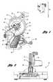
- FIG. 1is a side elevation view of a miter saw
- FIG. 2is a front elevation view partially in cross section of a miter saw having a laser arbor
- FIG. 3is a perspective view of a miter saw just prior to cutting a workpiece
- FIG. 4is a fragmentary side perspective view of a miter saw having a plotted laser light line projecting on a workpiece;
- FIG. 5is a fragmentary perspective view showing a solid laser line projected on a workpiece just prior to cutting
- FIG. 6is a side elevation view of a movable guard
- FIG. 7is a fragmentary view taken along line 6 — 6 in FIG. 5;
- FIG. 8is a fragmentary front elevation view of a saw blade and laser arbor
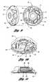
- FIG. 9is a plan view of a partially disassembled laser arbor
- FIG. 10is a perspective view of a laser arbor having a laser module mounted on an arcuate mounting surface
- FIG. 11is a cross-sectional view of a laser arbor having a laser module mounted on an arcuate mounting surface.
- the miter saw 10having a circular saw blade 12 is shown.
- the miter saw 10also includes a base 14 and fence 16 against which a workpiece 18 is located when the workpiece 18 is cut by the miter saw 10 .
- An arm 20connects the motor assembly 22 that forms part of the saw head assembly, generally indicated by reference numeral 24 .
- the saw head assembly 24includes a circular saw blade 12 and also includes a fixed guard 28 and movable shield 30 as well as a handle 32 that includes the power switch 34 .
- the saw 10 shown in the illustrated embodimentis a compound miter saw having a miter angle adjustment mechanism 38 and a tilt adjustment mechanism 40 . While the illustrated embodiment is of a compound miter saw, the invention is equally applicable to a simple miter saw, a sliding compound miter saw, or a chop saw.
- the saw head assembly 24is pivotally connected to the arm 20 and includes a spring (not shown) for biasing the saw head assembly 24 out of engagement with the workpiece 18 .
- the operatorgrips the handle 32 and pulls it down toward the workpiece 18 as he depresses the power switch 34 causing the circular saw blade 12 to rotate.
- the miter angle adjustment mechanism 38permits the base 14 to rotate relative to the arm 20 to change the transverse angle of cut.
- the tilt adjustment mechanism 40allows the saw head assembly 24 to be pivoted and the transverse inclination of the blade to be adjusted.
- a miter saw 10 having a laser arbor 42is illustrated.
- the laser arbor 42is mounted adjacent the saw blade 12 on the same spindle 44 as the saw blade.
- the laser arbor 42directs a laser beam 48 in a plane as the laser arbor 42 is rotated by the spindle 44 .
- the light beamis tilted toward the blade edge.
- the light sourceis described as a laser, another battery operated light source such as a light emitting diode (LED), focused electric light bulb based system or small flashlight could be used with the miter saw 10 .
- the structure of the laser arbor 42will be more specifically described below with reference to FIGS. 8 and 9.
- a light beam 48is formed by a dot, directed in a plane tilted inwardly toward the blade edge.
- the light beamcould be projected parallel to the plane of the circular saw blade 12 to indicate the starting edge of the blade cut.
- the miter saw 10is shown just prior to the saw blade 12 cutting the workpiece 18 .
- the saw head assembly 24has been pivoted on the arm 20 .
- the movable shield 30has been rotated by the link 50 to a position partially overlying the fixed guard 28 .
- the movable shield 30is still covering the portions of the saw blade 12 that are not within the fixed guard 28 and not adjacent the workpiece 18 .
- a dotted line 52is projected on the workpiece 18 as shown in FIG. 3 when the power switch 34 is actuated and the movable shield 30 is in the position shown in FIG. 1 .
- the laser arborforms a solid line 54 on the workpiece 18 as shown in FIGS. 6 and 7.
- line 52can be formed as a solid line instead of a dotted/dashed line.
- the dotted line shown in FIG. 3permits the alignment of the workpiece with the base 14 to be immediately assessed by actuating the power switch 34 even prior to lowering the saw head assembly 24 .
- the solid line 54 formed by the laser beam 48indicates the position of the cut just prior to and during the cutting operation, as shown in FIG. 5 .
- the shieldhas a series of slits 56 or openings.
- the movable shield 30may be formed of an opaque or a transparent material. If the movable shield 30 is formed of a transparent material, an opaque mask 58 is provided on the peripheral edge 60 of the shield 30 that prevents the laser beam 48 from being projected upwardly toward the eyes of an operator.
- a range of normal operator eye positionis indicated by reference numeral 62 .
- the range of normal operator eye position 62corresponds to the expected position of the operator's eyes taking into account the expected eye level of any operator in a wide range of heights and also regardless of whether the operator is sitting or standing.
- the laser beam 48is not permitted to be projected, in this normal eye position 62 , regardless of the position of the saw head assembly 24 .
- the laser beam 48projects through the slits 56 to form the dotted line 52 on the workpiece 18 .
- the portion of the shield 30 including the slits 56are shifted from between the saw blade 12 and the workpiece 18 .
- a single transparent areacan be formed in the shield so that a solid line is formed on the workpiece when the shield is in the position of FIG. 1 .
- the laser arbor 42includes a washer 64 upon which components are mounted and a cover 66 that covers and protects the laser arbor components mounted on the washer 64 , or arbor base.
- Laser arbor 42includes a laser module 68 that is powered by batteries 70 .
- the batteries 70are mounted in battery receptacles 72 a in the cover 66 .
- the batteriesare received in cooperating battery receptacles 72 b (best seen in FIG. 10) formed in the washer 64 when the cover is properly placed on the base.
- Spring contacts 73are provided on the washer 64 to establish electrical contact with the batteries when the cover 66 is properly secured to the washer 64 .
- the laser module 68is operated by a reed switch 74 or equivalent centrifugally actuated switch.
- the reed switch 74only supplies power to the laser module 68 when the saw blade 12 is rotated above the predetermined rotational speed.
- a printed circuit board 76is provided to control the operation of the laser arbor 42 in conjunction with the reed switch 74 .
- the laser moduleincludes a lens 78 that directs the laser beam 48 through an opening 80 in the laser arbor 42 .
- the laser module 68may be mounted in the laser arbor 42 on the washer 64 , or arbor base, having an arcuate mounting surface 82 .
- the laser module 68has a housing 84 that includes a complimentary arcuate mounting surface 86 .
- the laser module 68is secured to the laser arbor with the arcuate mounting surfaces 82 , 86 in contact with each other.
- the laser module 68is held on arcuate mounting surfaces 82 , 86 with the lens 78 and opening 80 disposed at a slight angle of inclination to be directed toward the teeth of the circular saw blade 12 .
- a set screw 88 , glue or other bonding agentis used to lock the laser module 68 on the mounting surface 82 .
- the laser moduleis preferably held at a slight angle relative to the saw blade so that the laser beam 48 is formed on the workpiece in alignment with the edge of the blades when the arbor is rotated.
- the laser beam 48can be projected as close as possible to the point at which the saw blade 12 will cut the workpiece 18 so that markings corresponding to the desired location of cut on the workpiece 18 can be closely aligned with the laser beam 48 both when projected preliminarily as a solid or dotted line 52 and when projected as a solid line 54 .
Landscapes
- Engineering & Computer Science (AREA)
- Mechanical Engineering (AREA)
- Life Sciences & Earth Sciences (AREA)
- Physics & Mathematics (AREA)
- Optics & Photonics (AREA)
- Wood Science & Technology (AREA)
- Forests & Forestry (AREA)
- Sawing (AREA)
Abstract
Description
Claims (19)
Priority Applications (12)
| Application Number | Priority Date | Filing Date | Title |
|---|---|---|---|
| US09/860,898US6755107B2 (en) | 2001-05-18 | 2001-05-18 | Miter saw having a light beam alignment system |
| CA 2359453CA2359453C (en) | 2001-05-18 | 2001-10-17 | Miter saw having a light beam alignment system |
| AU83640/01AAU8364001A (en) | 2001-05-18 | 2001-10-26 | Miter saw having a light beam alignment system |
| EP20010309338EP1258305B1 (en) | 2001-05-18 | 2001-11-02 | Miter saw having a light beam alignment system |
| JP2001337423AJP2002347002A (en) | 2001-05-18 | 2001-11-02 | Circular saw equipped with beam aligning mechanism |
| DE2001606396DE60106396T2 (en) | 2001-05-18 | 2001-11-02 | Miter saw with beam alignment system |
| EP20040018171EP1470883B1 (en) | 2001-05-18 | 2001-11-02 | Miter saw having a light beam alignment system |
| CNB011378506ACN1301186C (en) | 2001-05-18 | 2001-11-02 | A miter saw with a beam alignment system |
| DE2001633141DE60133141T2 (en) | 2001-05-18 | 2001-11-02 | Miter saw with beam alignment system |
| HK03104493.1AHK1052154A1 (en) | 2001-05-18 | 2003-06-23 | Miter saw having a light beam alignment system |
| US10/774,854US20040159199A1 (en) | 2001-05-18 | 2004-02-09 | Miter saw having a light beam alignment system |
| US11/156,358US7398719B2 (en) | 2001-05-18 | 2005-06-17 | Miter saw having a light beam alignment system |
Applications Claiming Priority (1)
| Application Number | Priority Date | Filing Date | Title |
|---|---|---|---|
| US09/860,898US6755107B2 (en) | 2001-05-18 | 2001-05-18 | Miter saw having a light beam alignment system |
Related Child Applications (1)
| Application Number | Title | Priority Date | Filing Date |
|---|---|---|---|
| US10/774,854ContinuationUS20040159199A1 (en) | 2001-05-18 | 2004-02-09 | Miter saw having a light beam alignment system |
Publications (2)
| Publication Number | Publication Date |
|---|---|
| US20020170404A1 US20020170404A1 (en) | 2002-11-21 |
| US6755107B2true US6755107B2 (en) | 2004-06-29 |
Family
ID=25334307
Family Applications (3)
| Application Number | Title | Priority Date | Filing Date |
|---|---|---|---|
| US09/860,898Expired - Fee RelatedUS6755107B2 (en) | 2001-05-18 | 2001-05-18 | Miter saw having a light beam alignment system |
| US10/774,854AbandonedUS20040159199A1 (en) | 2001-05-18 | 2004-02-09 | Miter saw having a light beam alignment system |
| US11/156,358Expired - Fee RelatedUS7398719B2 (en) | 2001-05-18 | 2005-06-17 | Miter saw having a light beam alignment system |
Family Applications After (2)
| Application Number | Title | Priority Date | Filing Date |
|---|---|---|---|
| US10/774,854AbandonedUS20040159199A1 (en) | 2001-05-18 | 2004-02-09 | Miter saw having a light beam alignment system |
| US11/156,358Expired - Fee RelatedUS7398719B2 (en) | 2001-05-18 | 2005-06-17 | Miter saw having a light beam alignment system |
Country Status (8)
| Country | Link |
|---|---|
| US (3) | US6755107B2 (en) |
| EP (2) | EP1470883B1 (en) |
| JP (1) | JP2002347002A (en) |
| CN (1) | CN1301186C (en) |
| AU (1) | AU8364001A (en) |
| CA (1) | CA2359453C (en) |
| DE (2) | DE60133141T2 (en) |
| HK (1) | HK1052154A1 (en) |
Cited By (46)
| Publication number | Priority date | Publication date | Assignee | Title |
|---|---|---|---|---|
| US20030116000A1 (en)* | 2001-07-31 | 2003-06-26 | Raymond Caluori | Angled light beam rotary saw cut alignment device |
| US20030233921A1 (en)* | 2002-06-19 | 2003-12-25 | Garcia Jaime E. | Cutter with optical alignment system |
| US20040182215A1 (en)* | 2003-03-20 | 2004-09-23 | Shigeharu Ushiwata | Miter saw having light beam projection device |
| US20040194600A1 (en)* | 2003-04-01 | 2004-10-07 | Chyi-Yiing Wu | Self-powered rotary optical aligning apparatus |
| US20040221702A1 (en)* | 2003-05-08 | 2004-11-11 | P & F Brother Industrial Corporation | Cutting apparatus with a position adjustable light-emitting unit |
| US20050011325A1 (en)* | 2002-07-29 | 2005-01-20 | Caluori Raymond J. | Light beam rotary saw cut alignment device |
| US20050094386A1 (en)* | 2003-10-10 | 2005-05-05 | Ross Zhang | Sawing direction positioning system for a bench saw |
| US20050117613A1 (en)* | 2003-11-18 | 2005-06-02 | Tung Hsin C. | Laser alignment device of a circular saw machine |
| US20050166737A1 (en)* | 2002-07-29 | 2005-08-04 | Caluori Raymond J. | Positive-angled light beam rotary saw cut alignment device |
| US20050195592A1 (en)* | 2004-03-08 | 2005-09-08 | Hung - Chi Hsu | Handsaw having sawing guide function |
| US20050217445A1 (en)* | 2001-05-18 | 2005-10-06 | One World Technologies Limited | Miter saw having a light beam alignment system |
| US20060037445A1 (en)* | 2004-08-18 | 2006-02-23 | Sergyeyenko Oleksiy P | Circular saw with laser and protractor |
| US20060080850A1 (en)* | 2004-10-20 | 2006-04-20 | Robert Firth | Guidance light generating unit for power tool |
| US20060101965A1 (en)* | 2002-12-16 | 2006-05-18 | Carroll Craig A | Pivoting rear blade guard |
| US20060101975A1 (en)* | 2002-02-15 | 2006-05-18 | Alan Phillips | Blade clamp assembly |
| US20060162513A1 (en)* | 2005-01-21 | 2006-07-27 | General Binding Corporation | Trimmer with light guidance |
| US20060213341A1 (en)* | 2005-03-01 | 2006-09-28 | Blue Collar Ventures, L.L.C. | Movable saw apparatus and method |
| US20060213347A1 (en)* | 2005-03-28 | 2006-09-28 | Der-Shyang Jan | Cutting line indicator |
| US20060277768A1 (en)* | 2005-04-29 | 2006-12-14 | Van Rijen Johannes G | Electric tool for shaping of an object |
| US20070034065A1 (en)* | 2005-08-10 | 2007-02-15 | Rexon Industrial Corporation Ltd. | Laser marker for circular-saw machine |
| EP1759797A1 (en) | 2005-09-05 | 2007-03-07 | Quarton Inc. | Cutting line indicator |
| US20070107235A1 (en)* | 2005-11-15 | 2007-05-17 | Eastway Fair Company Limited Of Trident Chambers | Light assembly for circular saw |
| US20070219559A1 (en)* | 2006-03-17 | 2007-09-20 | Zimmer Technology, Inc. | Indicator device for use with a surgical guide instrument |
| US20070289513A1 (en)* | 2006-06-16 | 2007-12-20 | Hsin-Chin Chen | Adjusting structure of a laser indicator of a sawing machine |
| US20080017005A1 (en)* | 2006-07-18 | 2008-01-24 | Hsin-Chih Tung | Light path molding apparatus of cutting machine tool |
| US20080034931A1 (en)* | 2006-08-10 | 2008-02-14 | Nash Derek J | Laser guide |
| US7343841B2 (en)* | 2002-02-15 | 2008-03-18 | Black & Decker Inc. | Blade clamp assembly |
| US20080105100A1 (en)* | 2006-11-08 | 2008-05-08 | Eastway Fair Company Limited | Adjustable laser module |
| US20080105658A1 (en)* | 2006-11-08 | 2008-05-08 | Eastway Fair Company Limited | Laser module with laser generator control switch |
| US20080121082A1 (en)* | 2006-11-08 | 2008-05-29 | Eastway Fair Company Limited | Cutting device and laser module for use therewith |
| US20080137339A1 (en)* | 2006-12-06 | 2008-06-12 | Nash Derek J | Laser guide |
| US20080289193A1 (en)* | 2005-12-27 | 2008-11-27 | Justus Lamprecht | Safety Guard For A Hand-Guided Tool |
| US20090077816A1 (en)* | 2007-09-21 | 2009-03-26 | Black & Decker Inc. | Adjustable and removable keel assembly and blade guide for a jigsaw |
| US20090077814A1 (en)* | 2007-09-21 | 2009-03-26 | Black & Decker Inc. | Cutting Angle Indicator in Jigsaw Housing with Dust Extraction |
| US20090077818A1 (en)* | 2007-09-21 | 2009-03-26 | Black & Decker Inc. | Housing of a cutting tool including blade storage, integral blade guard and motor ventilation pathway |
| US20090313831A1 (en)* | 2004-05-28 | 2009-12-24 | Scientific Molding Corporation Ltd. | Hand-held circular saw, in particular plunge-cut saw |
| US7735403B2 (en) | 2006-09-26 | 2010-06-15 | Robert Bosch Gmbh | Alignment system for a fence for a table saw |
| US20110030228A1 (en)* | 2008-04-11 | 2011-02-10 | Bic-Violex Sa | Razor handle having a retractable razor head carrier and a movable flap, and razor having such a handle |
| US8578615B2 (en) | 2011-09-12 | 2013-11-12 | Black & Decker Inc. | Jigsaw with deployable keel and tiltable shoe |
| US8726526B2 (en) | 2009-03-05 | 2014-05-20 | Max Co., Ltd. | Portable cutting machine |
| US9162298B2 (en) | 2013-03-07 | 2015-10-20 | Rexon Industrial Corp., Ltd. | Laser alignment device for circular saw |
| US20160151930A1 (en)* | 2014-12-02 | 2016-06-02 | Robert Bosch Gmbh | Cut-Length Indicating Device |
| US9827623B2 (en) | 2007-09-21 | 2017-11-28 | Black & Decker Inc. | Control of reciprocation speed and orbital magnitude of a jigsaw with a plurality of material and/or task descriptive icons |
| US9899899B2 (en) | 2013-10-25 | 2018-02-20 | Black & Decker Inc. | Handheld power tool with compact AC switch |
| US10189153B2 (en) | 2016-03-25 | 2019-01-29 | Sonny Frank | Leveling device assembly for a hydraulic hammer |
| US10882123B2 (en) | 2015-02-25 | 2021-01-05 | Milwaukee Electric Tool Corporation | Miter saw |
Families Citing this family (54)
| Publication number | Priority date | Publication date | Assignee | Title |
|---|---|---|---|---|
| US7207251B2 (en) | 1999-02-05 | 2007-04-24 | Hitachi Koki Co., Ltd. | Cutter with laser generator that irradiates cutting position on workpiece to facilitate alignment of blade with cutting position |
| US7159497B2 (en)* | 2002-01-25 | 2007-01-09 | Eastway Fair Company Ltd. | Light beam alignment system |
| US7369916B2 (en) | 2002-04-18 | 2008-05-06 | Black & Decker Inc. | Drill press |
| US8004664B2 (en) | 2002-04-18 | 2011-08-23 | Chang Type Industrial Company | Power tool control system |
| US7359762B2 (en) | 2002-04-18 | 2008-04-15 | Black & Decker Inc. | Measurement and alignment device including a display system |
| US20060076385A1 (en) | 2002-04-18 | 2006-04-13 | Etter Mark A | Power tool control system |
| US7073268B1 (en) | 2002-04-18 | 2006-07-11 | Black & Decker Inc. | Level apparatus |
| CN2561565Y (en)* | 2002-05-14 | 2003-07-23 | 南京泉峰国际贸易有限公司 | Electric annular saw with laser aligning device |
| TW554813U (en)* | 2002-09-26 | 2003-09-21 | P & F Brother Ind Corp | Lifting structure for eye shielding cover of cutting machine |
| US7137327B2 (en) | 2002-10-31 | 2006-11-21 | Black & Decker Inc. | Riving knife assembly for a dual bevel table saw |
| DE102004033576B4 (en)* | 2003-01-15 | 2007-02-22 | Gottlieb Nestle Gmbh | marking |
| DE10301440B4 (en)* | 2003-01-15 | 2005-03-03 | Gottlieb Nestle Gmbh | marking |
| US7290474B2 (en) | 2003-04-29 | 2007-11-06 | Black & Decker Inc. | System for rapidly stopping a spinning table saw blade |
| US20050188808A1 (en)* | 2003-12-02 | 2005-09-01 | Michael Parrish | Trimmer with laser guide |
| US7770502B2 (en)* | 2003-12-02 | 2010-08-10 | Elmer's Products Inc | Laser-guided paper trimmer |
| JP4656376B2 (en)* | 2004-06-30 | 2011-03-23 | 日立工機株式会社 | Tabletop cutting machine |
| US7243440B2 (en) | 2004-10-06 | 2007-07-17 | Black & Decker Inc. | Gauge for use with power tools |
| US7219437B2 (en)* | 2005-01-28 | 2007-05-22 | Brent Dallman | Laser guided work device |
| US20060168828A1 (en)* | 2005-01-28 | 2006-08-03 | Brent Dallman | Laser guided work device |
| CA2542570A1 (en)* | 2005-04-13 | 2006-10-13 | Black & Decker Inc. | Chop saw |
| US20080163505A1 (en)* | 2007-01-09 | 2008-07-10 | Hsu Chin-Ho | Laser Indicated Pneumatic Cutter |
| US20090077817A1 (en)* | 2007-09-21 | 2009-03-26 | Black & Decker Inc. | Dash-dot laser cutting guide tiltable from a housing for battery replacement |
| US8067916B2 (en)* | 2008-01-23 | 2011-11-29 | Su Hak Auh | Power cutting tool with synchronized dust control device |
| TW200938352A (en)* | 2008-03-05 | 2009-09-16 | Durq Machinery Corp | Miter saw with safety positioning structure of protection cap |
| US20090313833A1 (en)* | 2008-06-18 | 2009-12-24 | Fiskars Brands, Inc. | Material trimmer with illuminated cut line indicator |
| TWI332445B (en)* | 2008-12-05 | 2010-11-01 | Pegatron Corp | Stapler |
| CN101745690B (en)* | 2008-12-19 | 2012-03-28 | 苏州宝时得电动工具有限公司 | Bench saw |
| JP5444736B2 (en)* | 2009-01-29 | 2014-03-19 | 日立工機株式会社 | Engine cutter, engine cutter with wheels, and cutting method |
| US8398176B2 (en)* | 2009-06-03 | 2013-03-19 | Asphalt Zipper, Inc. | Asphalt milling attachment with depth control and bit access |
| CN102157111A (en)* | 2010-02-11 | 2011-08-17 | 张皓 | LED (Light Emitting Diode) graphic display device |
| US10265787B2 (en)* | 2010-04-28 | 2019-04-23 | Robert Bosch Tool Corporation | Laser alignment system for saw |
| US20120085214A1 (en)* | 2010-10-08 | 2012-04-12 | Robert Bosch Gmbh | Light guide alignment device for power tool |
| US8667877B2 (en) | 2010-10-22 | 2014-03-11 | Robert Bosch Gmbh | Miter saw with dual tracking light |
| US8616102B2 (en)* | 2011-04-07 | 2013-12-31 | Robert Bosch Gmbh | Optical alignment device for a table saw |
| US20120255414A1 (en)* | 2011-04-07 | 2012-10-11 | Robert Bosch Gmbh | Modular Laser Alignment Device for Power Tool |
| WO2016085864A1 (en) | 2014-11-26 | 2016-06-02 | International Paper Company | Paper trim cut measurement device and method |
| US10239220B2 (en)* | 2014-12-12 | 2019-03-26 | Antonio Mele | Laser device battery powered, which shows the cutting path to get equal portions of a cake, pizza or similar food |
| DE102014226025A1 (en)* | 2014-12-16 | 2016-06-16 | Robert Bosch Gmbh | Optical display device unit for use in an external application unit |
| JP6480274B2 (en)* | 2015-06-22 | 2019-03-06 | 日立Geニュークリア・エナジー株式会社 | Rotating tool, processing state monitoring device and machine tool |
| CN105345619A (en)* | 2015-11-26 | 2016-02-24 | 吴江市液铸液压件铸造有限公司 | Casting grinding machine preventing scraps and vibration |
| JP6847648B2 (en)* | 2016-12-05 | 2021-03-24 | 株式会社マキタ | Cutting machine |
| EP3446842A1 (en) | 2017-08-24 | 2019-02-27 | Basell Polyolefine GmbH | Method for aligning a cutter plate of a pelletizer using a remote alignment adjustment device |
| EP3498444B1 (en)* | 2017-12-13 | 2021-03-03 | Scheppach Fabrikation von Holzbearbeitungsmaschinen GmbH | Saw |
| EP3781343B1 (en)* | 2018-04-20 | 2023-06-14 | Struers ApS | Method of indicating cuts to be carried out and cutting machines |
| USD945234S1 (en)* | 2018-07-26 | 2022-03-08 | Paul Mueller Company | Guard for use with a power tool |
| DE102019200366A1 (en) | 2019-01-14 | 2020-07-16 | Festool Gmbh | Saw blade cover, fence unit and table saw |
| CN111085877A (en)* | 2019-12-02 | 2020-05-01 | 常德市鼎鑫机械有限公司 | Metal product's side cut device |
| US11213903B2 (en)* | 2020-01-03 | 2022-01-04 | Dmt Holdings, Inc. | Sawing machine |
| WO2021212131A1 (en) | 2020-04-17 | 2021-10-21 | Wright Medical Technology, Inc. | Minimally invasive surgery laser guide |
| CN113183247A (en)* | 2020-06-24 | 2021-07-30 | 浙江金一电动工具有限公司 | Floor saw with labor-saving and high safety |
| CN113172707A (en)* | 2020-06-24 | 2021-07-27 | 浙江金一电动工具有限公司 | Saw blade dismounting device of floor saw |
| US20230158703A1 (en) | 2020-06-25 | 2023-05-25 | Festool Gmbh | Bevel saws configured to make a bevel cut in a workpiece |
| JP7555783B2 (en)* | 2020-10-15 | 2024-09-25 | 株式会社マキタ | Benchtop cutting machine |
| JP7568545B2 (en)* | 2021-03-02 | 2024-10-16 | 株式会社マキタ | Cutting machine |
Citations (26)
| Publication number | Priority date | Publication date | Assignee | Title |
|---|---|---|---|---|
| US4257297A (en) | 1979-01-31 | 1981-03-24 | Peter Nidbella | Circular saw with visual cut line indicator |
| US4335510A (en) | 1980-06-18 | 1982-06-22 | Black & Decker, Inc. | String trimmer |
| US4450627A (en) | 1981-07-06 | 1984-05-29 | Shindaiwa Kogyo Co., Ltd. | Device for determining a correct sawing position for a portable rotary sawing machine |
| US4469931A (en) | 1982-09-13 | 1984-09-04 | Macken John A | Laser assisted saw device |
| US4503740A (en) | 1982-01-18 | 1985-03-12 | Capital Machine Company, Inc. | Optical cutting edge locator for a cutting apparatus |
| US4805504A (en)* | 1986-12-29 | 1989-02-21 | Makita Electric Works, Ltd. | Safety cover for miter saw |
| US4833782A (en) | 1987-06-01 | 1989-05-30 | Robert E. Strauss | Saber saw tracing light |
| US4885967A (en) | 1988-08-25 | 1989-12-12 | J. Gibson Mcilvain Company | Laser alignment device for sawmills |
| DE3922849A1 (en) | 1989-07-12 | 1991-01-24 | Reich Maschf Gmbh Karl | Cutting indicator for circular hand-saw - uses laser beam to guide blade precisely around cutting pattern |
| US5038481A (en) | 1990-05-04 | 1991-08-13 | Lonnie Smith | Saber saw tracking light |
| US5060384A (en) | 1990-12-06 | 1991-10-29 | Inertia Dynamics Corporation | Automatic head for a line trimmer |
| US5121188A (en) | 1990-05-16 | 1992-06-09 | Applied Laser Systems | Laser module assembly |
| US5199343A (en)* | 1991-10-09 | 1993-04-06 | Black & Decker Inc. | Power saw with louvered blade guard |
| US5285708A (en)* | 1992-05-18 | 1994-02-15 | Porter-Cable Corporation | Miter saw alignment system |
| US5375495A (en)* | 1992-05-18 | 1994-12-27 | Porter-Cable Corporation | Optical alignment system for circular power saws |
| US5446635A (en) | 1993-06-24 | 1995-08-29 | Quarton, Inc. | Laser assembly for marking a line on a workpiece for guiding a cutting tool |
| US5461790A (en) | 1994-02-16 | 1995-10-31 | Olstowski; Franek | Circular saws with laser guides for more precise movement during cutting |
| US5630277A (en) | 1994-08-18 | 1997-05-20 | Kabushiki Kaisha Ogura | Portable, power driven punching machine having an aiming beam |
| US5675899A (en) | 1996-05-28 | 1997-10-14 | Webb; James | Rotary saw with laser beam alignment |
| US5862727A (en)* | 1996-03-11 | 1999-01-26 | Kelly; Robert R. | Laser arbor |
| US5911482A (en)* | 1996-05-31 | 1999-06-15 | Black & Decker, Inc. | Window assembly and lower saw guard |
| US5996460A (en)* | 1992-03-13 | 1999-12-07 | Waite; Lance H. | Cut line indicator for power cutting material |
| US6035757A (en)* | 1997-12-15 | 2000-03-14 | Caluori; Raymond | Rotary saw cut alignment device |
| USD424076S (en) | 1999-02-24 | 2000-05-02 | Black & Decker Inc. | Mounting device for a cutting tool |
| US6073621A (en) | 1997-08-25 | 2000-06-13 | Cetrangolo; Dolivio L. | Apparatus for automatic layout and cutting corner lines in stone |
| US6203112B1 (en) | 1999-05-03 | 2001-03-20 | American Standards Construction Corp. | Attachable road cutting apparatus |
Family Cites Families (104)
| Publication number | Priority date | Publication date | Assignee | Title |
|---|---|---|---|---|
| US3123111A (en)* | 1964-03-03 | Sawdust discharge for circular saw | ||
| US1476238A (en) | 1922-02-20 | 1923-12-04 | Sumner M Bump | Indicator for edging saws |
| US1804764A (en) | 1928-12-01 | 1931-05-12 | Edwin J Grant | Apparatus for and method of cutting material |
| US1993219A (en) | 1933-07-12 | 1935-03-05 | Herberts Machinery Company Ltd | Circular saw |
| US2095330A (en) | 1936-07-25 | 1937-10-12 | Duro Metal Prod Co | Bench saw |
| US2167189A (en)* | 1937-02-27 | 1939-07-25 | Verderber Joseph | Machine tool |
| US2267189A (en)* | 1940-01-11 | 1941-12-23 | Brown Brockmeyer Co Inc | Combined shield and illuminating means for grinding wheels |
| US2307820A (en) | 1940-02-20 | 1943-01-12 | Charles M Butters | Shadow-line indicator for trimming saws |
| US2313686A (en) | 1941-03-17 | 1943-03-09 | Uremovich Mark | Saw guard |
| US2357194A (en) | 1942-01-13 | 1944-08-29 | Cincinnati Shaper Co | Gauging device |
| US2488947A (en) | 1945-05-28 | 1949-11-22 | American Floor Surfacing Mach | Rotary power handsaw |
| US2440950A (en)* | 1945-08-04 | 1948-05-04 | John H Hill | Machine for cutting work pieces |
| GB599718A (en) | 1945-10-30 | 1948-03-18 | Sidney Robert Littlejohn | Improvements relating to guards for saw benches |
| US2623555A (en) | 1948-07-14 | 1952-12-30 | Rockwell Mfg Co | Saw guard |
| GB674894A (en) | 1949-05-18 | 1952-07-02 | John Edward Roe | Improvements in or relating to safety devices for circular saws |
| CH323681A (en)* | 1954-04-23 | 1957-08-15 | Raimann Gmbh B | Directional lighting system on woodworking machines, e.g. B. gang saws, circular saws or the like |
| GB782280A (en) | 1954-11-16 | 1957-09-04 | British Celanese | Improvements in or relating to safety guards |
| US2876810A (en)* | 1958-03-04 | 1959-03-10 | Joseph M Peterson | Point of operation saw guard |
| GB961484A (en)* | 1962-03-02 | 1964-06-24 | Sunbeam Corp | A portable electric saw |
| US3232326A (en) | 1962-10-04 | 1966-02-01 | Rockwell Mfg Co | Blade guard and splitter assembly for table saws |
| US3496814A (en) | 1967-04-22 | 1970-02-24 | Canadian Converters Co Ltd | Method of blending designs |
| US3780777A (en) | 1971-10-06 | 1973-12-25 | Oliver Machinery Co | Defecting saw |
| US4078869A (en) | 1977-01-17 | 1978-03-14 | Honeycutt Damon P | Two-way right angle drill |
| GB2065995A (en) | 1979-12-12 | 1981-07-01 | Bicc Burdny Ltd | Electric connection method and tool for use therein |
| DD154866A3 (en) | 1980-02-29 | 1982-04-28 | Volker Eichler | DEVICE FOR CONTROLLING A PRINTING MACHINE |
| DE3104340C2 (en) | 1980-03-06 | 1986-06-05 | AEG Power Tool Corp. (APTC), Norwich, Conn. | Portable circular saw |
| FR2491614A1 (en) | 1980-10-08 | 1982-04-09 | Couturier Alain | METHOD FOR POSITIONING REFERENCE POINTS ON AN ADJUSTABLE TEMPLATE |
| US4413662A (en) | 1981-06-08 | 1983-11-08 | Forest Industries Machine Corp. | Edging system |
| US4651732A (en) | 1983-03-17 | 1987-03-24 | Frederick Philip R | Three-dimensional light guidance system for invasive procedures |
| DE3500371A1 (en) | 1985-01-08 | 1986-07-10 | Licentia Patent-Verwaltungs-Gmbh, 6000 Frankfurt | Portable electric circular saw |
| US4836671A (en) | 1985-04-08 | 1989-06-06 | Charles Lescrenier | Locating device |
| US4805500A (en)* | 1985-06-29 | 1989-02-21 | Amada Company, Limited | Horizontal band saw machine |
| US4598481A (en) | 1985-08-12 | 1986-07-08 | Hein-Werner Corporation | Intersecting laser alignment apparatus and method |
| US4676130A (en) | 1986-02-25 | 1987-06-30 | Filer & Stowell Co., Inc. | Lumber edger |
| US4725933A (en) | 1986-09-11 | 1988-02-16 | Fairway International, Inc. | Line guide projector |
| DE3733028A1 (en)* | 1986-09-30 | 1988-04-07 | Pioneer Electronic Corp | RADIO RECEIVER WITH AUTOMATIC SEARCH SEARCH |
| AU98994S (en) | 1986-10-27 | 1987-12-17 | Ryobi Ltd | Electric mitre saw |
| US4817839A (en) | 1987-02-13 | 1989-04-04 | Ipco Corporation | Rotary saw and method for sectioning dental models |
| US4885965A (en) | 1987-02-13 | 1989-12-12 | Ipco Corporation | Rotary saw for sectioning dental models |
| US4887193A (en) | 1987-12-15 | 1989-12-12 | Dieckmann Ralf E | Mounting apparatus for a lamp or similar device |
| US4945797A (en) | 1988-05-06 | 1990-08-07 | Buss Automation, Inc. | Automated multiple rip saw feeding apparatus |
| US4934233B1 (en)* | 1988-06-29 | 1994-08-23 | Emerson Electric Co | Compound miter saw |
| US4892022A (en) | 1988-09-20 | 1990-01-09 | Robert Bosch Power Tool Corporation | Safety guard for sawing power tool particularly mitre saw |
| US5148232A (en) | 1991-01-28 | 1992-09-15 | Intra Corporation | Laser apparatus and method for aligning a crankpin grinding machine |
| DE4108710A1 (en) | 1991-03-16 | 1992-09-17 | Bosch Gmbh Robert | HAND MACHINE TOOL WITH GUIDE BEAM |
| US5181448A (en) | 1991-12-20 | 1993-01-26 | Emerson Electric Co. | Miter saw apparatus with adjustable workpiece supporting fence |
| US5316014A (en) | 1992-02-07 | 1994-05-31 | Livingston Products, Inc. | Biopsy locator and guide |
| US5320111A (en) | 1992-02-07 | 1994-06-14 | Livingston Products, Inc. | Light beam locator and guide for a biopsy needle |
| DE4236288C1 (en) | 1992-10-28 | 1993-12-09 | Dienes Werke | Longitudinally cutting machine with knife blade position inspection - has system of individual blades held at knife holder having lowering system so that blades are adjustable to assigned counter knife |
| USD346173S (en) | 1993-01-04 | 1994-04-19 | Black & Decker Inc. | Miter saw |
| US5439328A (en) | 1993-08-24 | 1995-08-08 | E. I. Du Pont De Nemours And Company | Single-head drill with video attachment |
| US5365822A (en) | 1993-09-17 | 1994-11-22 | Stapleton Michael F | Cutting guide |
| KR0158728B1 (en) | 1993-12-27 | 1999-01-15 | 마사카주 카키모토 | Drilling apparatus |
| EP0669792B1 (en) | 1994-02-28 | 1999-12-22 | Cybernetics Products, Inc. | Drill coordinate optimization for multi-layer printed circuit board |
| US5509337A (en) | 1994-08-12 | 1996-04-23 | Premark Feg Corporatin | Ring guard for food slicing machine blade |
| US5662017A (en) | 1994-09-28 | 1997-09-02 | Mellon; Ernesto Claude | Scroll saw |
| US5495784A (en) | 1994-09-29 | 1996-03-05 | Chen; Ruey-Zon | Cutting depth setting device for a saw machine |
| DE19501069A1 (en) | 1995-01-16 | 1996-07-18 | Wolfgang Kloess | Light sighting device for marking guide path of instrument, esp. diagnostic or therapeutic needle |
| CA2217489A1 (en) | 1995-04-04 | 1996-10-10 | Nigel Iivari Anderson | Light projection apparatus |
| US5755148A (en) | 1995-07-07 | 1998-05-26 | Black & Decker Inc. | Adjustable fence for a compound miter saw |
| USD372484S (en) | 1995-09-13 | 1996-08-06 | Black & Decker Inc. | Chop saw design |
| US6182548B1 (en) | 1995-10-10 | 2001-02-06 | Black & Decker Inc. | Guard and control apparatuses for sliding compound miter saw |
| US5957021A (en) | 1995-10-10 | 1999-09-28 | Black & Decker, Inc. | Guard and control apparatuses for sliding compound miter saw |
| US5724875A (en)* | 1995-10-10 | 1998-03-10 | Black & Decker Inc. | Guard and control apparatuses for sliding compound miter saw |
| US5741096A (en) | 1995-11-30 | 1998-04-21 | The Boeing Company | Line-laser assisted alignment apparatus |
| US5787801A (en) | 1996-05-03 | 1998-08-04 | Sunkist Growers, Inc. | Apparatus and method for coring and sectionizing fruit |
| US5822864A (en) | 1996-05-31 | 1998-10-20 | Black & Decker, Inc. | Viewing window for circular saw guard |
| USD388442S (en) | 1996-06-17 | 1997-12-30 | Makita Corporation | Miter saw |
| USD383765S (en) | 1996-07-03 | 1997-09-16 | Makita Corporation | Miter saw |
| DE19631306C2 (en) | 1996-08-02 | 2001-06-28 | Wolfgang Madlener | Laser light barrier system for tool and workpiece measurement |
| USD391973S (en) | 1996-12-02 | 1998-03-10 | Black & Decker Inc. | Sliding compound miter saw |
| US6263584B1 (en) | 1997-08-08 | 2001-07-24 | Barry S. Owens | Alignment apparatus and method of using same |
| USD400215S (en) | 1997-09-10 | 1998-10-27 | Black & Decker Inc. | Sliding compound miter saw |
| US6523447B2 (en) | 1997-09-26 | 2003-02-25 | Black & Decker Inc. | Cordless chop saw |
| US5949810A (en) | 1997-11-10 | 1999-09-07 | Jan A. Strand | Laser guide line system with cylindrical optic element |
| JP4067158B2 (en) | 1997-12-05 | 2008-03-26 | 日立工機株式会社 | Portable circular saw |
| US5918523A (en) | 1998-04-03 | 1999-07-06 | Cutter; Jack | System for guiding cutting tool |
| CA2276499C (en) | 1998-08-19 | 2004-10-26 | Sommerville Design & Manufacturing Inc. | Circular saw splitter device with integral anti-kick back |
| USD421267S (en) | 1998-10-06 | 2000-02-29 | Black & Decker Inc. | Sliding compound miter saw |
| USD420370S (en) | 1998-10-21 | 2000-02-08 | Makita Corporation | Miter saw |
| US7207251B2 (en) | 1999-02-05 | 2007-04-24 | Hitachi Koki Co., Ltd. | Cutter with laser generator that irradiates cutting position on workpiece to facilitate alignment of blade with cutting position |
| JP2001150401A (en) | 1999-11-26 | 2001-06-05 | Hitachi Koki Co Ltd | Chip removal equipment for cutting machine |
| JP2000225602A (en) | 1999-02-05 | 2000-08-15 | Hitachi Koki Co Ltd | Laser oscillator alignment mechanism of cutting machine |
| JP4200471B2 (en) | 1999-02-05 | 2008-12-24 | 日立工機株式会社 | Cutting machine |
| JP2001158003A (en) | 1999-12-03 | 2001-06-12 | Hitachi Koki Co Ltd | Cutting machine |
| JP3642969B2 (en) | 1999-02-09 | 2005-04-27 | 松下電器産業株式会社 | Laser processing apparatus and method |
| US6055734A (en) | 1999-03-04 | 2000-05-02 | Ryobi North America, Inc. | Circular saw with blade viewing window |
| USD428426S (en) | 1999-04-13 | 2000-07-18 | Ryobi North America, Inc. | Miter saw |
| USD423526S (en) | 1999-04-13 | 2000-04-25 | Ryobi North America, Inc. | Miter saw |
| JP3655124B2 (en) | 1999-05-14 | 2005-06-02 | 株式会社マキタ | Circular saw machine lighting equipment |
| USD425083S (en) | 1999-07-26 | 2000-05-16 | Delta International Machinery Corp. | Miter saw |
| US6481322B1 (en)* | 2000-01-13 | 2002-11-19 | Limate Corporation | Sawing apparatus combined with marking device |
| US6593587B2 (en) | 2000-03-10 | 2003-07-15 | Perceptron, Inc. | Non-contact measurement device for quickly and accurately obtaining dimensional measurement data |
| US20010034951A1 (en) | 2000-03-17 | 2001-11-01 | Sears John E. | Alignment tool apparatus and method |
| FR2807693B1 (en) | 2000-04-14 | 2002-08-02 | Georges Brun | DEVICE FOR DELIGNING LOW BOARDS |
| JP3874990B2 (en) | 2000-04-18 | 2007-01-31 | 株式会社マキタ | Lighting equipment for cutting machine |
| JP2001300902A (en) | 2000-04-21 | 2001-10-30 | Hitachi Koki Co Ltd | Chip removal device of cutting machine with laser oscillator |
| JP3546170B2 (en) | 2000-06-07 | 2004-07-21 | 敬一 葛西 | Laser beam oscillation structure and cutting device with laser beam oscillator |
| USD441771S1 (en) | 2000-06-08 | 2001-05-08 | Black & Decker Inc. | Miter saw |
| US6858857B2 (en) | 2000-11-10 | 2005-02-22 | Perceptron, Inc. | Modular non-contact measurement device for quickly and accurately obtaining dimensional measurement data |
| US6755107B2 (en) | 2001-05-18 | 2004-06-29 | One World Technologies Lmt. | Miter saw having a light beam alignment system |
| GB2382324A (en) | 2001-11-27 | 2003-05-28 | Rexon Co Ltd | Circular saw with cut line indication device |
| US6742430B2 (en) | 2002-03-18 | 2004-06-01 | Rexon Co., Ltd. | Circular sawing machine having a hidden-type infrared guide device |
| US6757984B2 (en) | 2002-06-11 | 2004-07-06 | David N. Harris | Saw guide for use with lined sheet material |
- 2001
- 2001-05-18USUS09/860,898patent/US6755107B2/ennot_activeExpired - Fee Related
- 2001-10-17CACA 2359453patent/CA2359453C/ennot_activeExpired - Fee Related
- 2001-10-26AUAU83640/01Apatent/AU8364001A/ennot_activeAbandoned
- 2001-11-02DEDE2001633141patent/DE60133141T2/ennot_activeExpired - Lifetime
- 2001-11-02EPEP20040018171patent/EP1470883B1/ennot_activeExpired - Lifetime
- 2001-11-02EPEP20010309338patent/EP1258305B1/ennot_activeExpired - Lifetime
- 2001-11-02CNCNB011378506Apatent/CN1301186C/ennot_activeExpired - Lifetime
- 2001-11-02DEDE2001606396patent/DE60106396T2/ennot_activeExpired - Lifetime
- 2001-11-02JPJP2001337423Apatent/JP2002347002A/enactivePending
- 2003
- 2003-06-23HKHK03104493.1Apatent/HK1052154A1/enunknown
- 2004
- 2004-02-09USUS10/774,854patent/US20040159199A1/ennot_activeAbandoned
- 2005
- 2005-06-17USUS11/156,358patent/US7398719B2/ennot_activeExpired - Fee Related
Patent Citations (27)
| Publication number | Priority date | Publication date | Assignee | Title |
|---|---|---|---|---|
| US4257297A (en) | 1979-01-31 | 1981-03-24 | Peter Nidbella | Circular saw with visual cut line indicator |
| US4335510A (en) | 1980-06-18 | 1982-06-22 | Black & Decker, Inc. | String trimmer |
| US4450627A (en) | 1981-07-06 | 1984-05-29 | Shindaiwa Kogyo Co., Ltd. | Device for determining a correct sawing position for a portable rotary sawing machine |
| US4503740A (en) | 1982-01-18 | 1985-03-12 | Capital Machine Company, Inc. | Optical cutting edge locator for a cutting apparatus |
| US4469931A (en) | 1982-09-13 | 1984-09-04 | Macken John A | Laser assisted saw device |
| US4805504A (en)* | 1986-12-29 | 1989-02-21 | Makita Electric Works, Ltd. | Safety cover for miter saw |
| US4833782A (en) | 1987-06-01 | 1989-05-30 | Robert E. Strauss | Saber saw tracing light |
| US4885967A (en) | 1988-08-25 | 1989-12-12 | J. Gibson Mcilvain Company | Laser alignment device for sawmills |
| DE3922849A1 (en) | 1989-07-12 | 1991-01-24 | Reich Maschf Gmbh Karl | Cutting indicator for circular hand-saw - uses laser beam to guide blade precisely around cutting pattern |
| US5038481A (en) | 1990-05-04 | 1991-08-13 | Lonnie Smith | Saber saw tracking light |
| US5121188A (en) | 1990-05-16 | 1992-06-09 | Applied Laser Systems | Laser module assembly |
| US5060384A (en) | 1990-12-06 | 1991-10-29 | Inertia Dynamics Corporation | Automatic head for a line trimmer |
| US5199343A (en)* | 1991-10-09 | 1993-04-06 | Black & Decker Inc. | Power saw with louvered blade guard |
| US5996460A (en)* | 1992-03-13 | 1999-12-07 | Waite; Lance H. | Cut line indicator for power cutting material |
| US6397717B1 (en)* | 1992-03-13 | 2002-06-04 | Lance H. Waite | Cut line indicator for power cutting material |
| US5375495A (en)* | 1992-05-18 | 1994-12-27 | Porter-Cable Corporation | Optical alignment system for circular power saws |
| US5285708A (en)* | 1992-05-18 | 1994-02-15 | Porter-Cable Corporation | Miter saw alignment system |
| US5446635A (en) | 1993-06-24 | 1995-08-29 | Quarton, Inc. | Laser assembly for marking a line on a workpiece for guiding a cutting tool |
| US5461790A (en) | 1994-02-16 | 1995-10-31 | Olstowski; Franek | Circular saws with laser guides for more precise movement during cutting |
| US5630277A (en) | 1994-08-18 | 1997-05-20 | Kabushiki Kaisha Ogura | Portable, power driven punching machine having an aiming beam |
| US5862727A (en)* | 1996-03-11 | 1999-01-26 | Kelly; Robert R. | Laser arbor |
| US5675899A (en) | 1996-05-28 | 1997-10-14 | Webb; James | Rotary saw with laser beam alignment |
| US5911482A (en)* | 1996-05-31 | 1999-06-15 | Black & Decker, Inc. | Window assembly and lower saw guard |
| US6073621A (en) | 1997-08-25 | 2000-06-13 | Cetrangolo; Dolivio L. | Apparatus for automatic layout and cutting corner lines in stone |
| US6035757A (en)* | 1997-12-15 | 2000-03-14 | Caluori; Raymond | Rotary saw cut alignment device |
| USD424076S (en) | 1999-02-24 | 2000-05-02 | Black & Decker Inc. | Mounting device for a cutting tool |
| US6203112B1 (en) | 1999-05-03 | 2001-03-20 | American Standards Construction Corp. | Attachable road cutting apparatus |
Cited By (72)
| Publication number | Priority date | Publication date | Assignee | Title |
|---|---|---|---|---|
| US20050217445A1 (en)* | 2001-05-18 | 2005-10-06 | One World Technologies Limited | Miter saw having a light beam alignment system |
| US7398719B2 (en) | 2001-05-18 | 2008-07-15 | Eastway Fair Company Limited | Miter saw having a light beam alignment system |
| US20030116000A1 (en)* | 2001-07-31 | 2003-06-26 | Raymond Caluori | Angled light beam rotary saw cut alignment device |
| US6915727B2 (en)* | 2001-07-31 | 2005-07-12 | Raymond Caluori | Angled light beam rotary saw cut alignment device |
| US7832319B2 (en)* | 2002-02-15 | 2010-11-16 | Black & Decker Inc. | Blade clamp assembly |
| US20080115645A1 (en)* | 2002-02-15 | 2008-05-22 | Alan Phillips | Blade clamp assembly |
| US7343841B2 (en)* | 2002-02-15 | 2008-03-18 | Black & Decker Inc. | Blade clamp assembly |
| US20060101975A1 (en)* | 2002-02-15 | 2006-05-18 | Alan Phillips | Blade clamp assembly |
| US20030233921A1 (en)* | 2002-06-19 | 2003-12-25 | Garcia Jaime E. | Cutter with optical alignment system |
| US7926398B2 (en) | 2002-06-19 | 2011-04-19 | Black & Decker Inc. | Cutter with optical alignment system |
| US20060101969A1 (en)* | 2002-06-19 | 2006-05-18 | Garcia Jaime E | Optical alignment system |
| US20050166737A1 (en)* | 2002-07-29 | 2005-08-04 | Caluori Raymond J. | Positive-angled light beam rotary saw cut alignment device |
| US7836806B2 (en)* | 2002-07-29 | 2010-11-23 | Caluori Raymond J | Positive-angled light beam rotary saw cut alignment device |
| US20050011325A1 (en)* | 2002-07-29 | 2005-01-20 | Caluori Raymond J. | Light beam rotary saw cut alignment device |
| US20060101965A1 (en)* | 2002-12-16 | 2006-05-18 | Carroll Craig A | Pivoting rear blade guard |
| US7243587B2 (en)* | 2002-12-16 | 2007-07-17 | Black & Decker Inc. | Pivoting rear blade guard |
| US20040182215A1 (en)* | 2003-03-20 | 2004-09-23 | Shigeharu Ushiwata | Miter saw having light beam projection device |
| US7387058B2 (en)* | 2003-03-20 | 2008-06-17 | Hitachi Koki Co., Ltd. | Miter saw having light beam projection device |
| US7168180B2 (en)* | 2003-04-01 | 2007-01-30 | Chyi-Yiing Wu | Self-powered rotary optical aligning apparatus |
| US20040194600A1 (en)* | 2003-04-01 | 2004-10-07 | Chyi-Yiing Wu | Self-powered rotary optical aligning apparatus |
| US6820528B1 (en)* | 2003-05-08 | 2004-11-23 | P&F Brother Industrial Corporation | Cutting apparatus with a position adjustable light-emitting unit |
| US20040221702A1 (en)* | 2003-05-08 | 2004-11-11 | P & F Brother Industrial Corporation | Cutting apparatus with a position adjustable light-emitting unit |
| US20050094386A1 (en)* | 2003-10-10 | 2005-05-05 | Ross Zhang | Sawing direction positioning system for a bench saw |
| US20050103176A1 (en)* | 2003-10-10 | 2005-05-19 | Ross Zhang | Sawing direction positioning system for a woodworking bandsaw |
| US7029149B2 (en)* | 2003-11-18 | 2006-04-18 | Hsin Chih Tung | Laser alignment device of a circular saw machine |
| US20050117613A1 (en)* | 2003-11-18 | 2005-06-02 | Tung Hsin C. | Laser alignment device of a circular saw machine |
| US20050195592A1 (en)* | 2004-03-08 | 2005-09-08 | Hung - Chi Hsu | Handsaw having sawing guide function |
| US20090313831A1 (en)* | 2004-05-28 | 2009-12-24 | Scientific Molding Corporation Ltd. | Hand-held circular saw, in particular plunge-cut saw |
| US20060037445A1 (en)* | 2004-08-18 | 2006-02-23 | Sergyeyenko Oleksiy P | Circular saw with laser and protractor |
| US20060080850A1 (en)* | 2004-10-20 | 2006-04-20 | Robert Firth | Guidance light generating unit for power tool |
| US20060162513A1 (en)* | 2005-01-21 | 2006-07-27 | General Binding Corporation | Trimmer with light guidance |
| US8910552B2 (en) | 2005-03-01 | 2014-12-16 | Blue Collar Ventures, L.L.C. | Movable saw apparatus and method |
| US20060213341A1 (en)* | 2005-03-01 | 2006-09-28 | Blue Collar Ventures, L.L.C. | Movable saw apparatus and method |
| US20060213347A1 (en)* | 2005-03-28 | 2006-09-28 | Der-Shyang Jan | Cutting line indicator |
| US20060277768A1 (en)* | 2005-04-29 | 2006-12-14 | Van Rijen Johannes G | Electric tool for shaping of an object |
| US20070034065A1 (en)* | 2005-08-10 | 2007-02-15 | Rexon Industrial Corporation Ltd. | Laser marker for circular-saw machine |
| EP1759797A1 (en) | 2005-09-05 | 2007-03-07 | Quarton Inc. | Cutting line indicator |
| US20070107235A1 (en)* | 2005-11-15 | 2007-05-17 | Eastway Fair Company Limited Of Trident Chambers | Light assembly for circular saw |
| US20080289193A1 (en)* | 2005-12-27 | 2008-11-27 | Justus Lamprecht | Safety Guard For A Hand-Guided Tool |
| US8882777B2 (en)* | 2006-03-17 | 2014-11-11 | Zimmer Technology, Inc. | Indicator device for use with a surgical guide instrument |
| US20070219559A1 (en)* | 2006-03-17 | 2007-09-20 | Zimmer Technology, Inc. | Indicator device for use with a surgical guide instrument |
| US20070289513A1 (en)* | 2006-06-16 | 2007-12-20 | Hsin-Chin Chen | Adjusting structure of a laser indicator of a sawing machine |
| US20080017005A1 (en)* | 2006-07-18 | 2008-01-24 | Hsin-Chih Tung | Light path molding apparatus of cutting machine tool |
| US20080034931A1 (en)* | 2006-08-10 | 2008-02-14 | Nash Derek J | Laser guide |
| US7735403B2 (en) | 2006-09-26 | 2010-06-15 | Robert Bosch Gmbh | Alignment system for a fence for a table saw |
| US20080105658A1 (en)* | 2006-11-08 | 2008-05-08 | Eastway Fair Company Limited | Laser module with laser generator control switch |
| US7556401B2 (en) | 2006-11-08 | 2009-07-07 | Eastway Fair Company Limited | Adjustable laser module |
| US20080105100A1 (en)* | 2006-11-08 | 2008-05-08 | Eastway Fair Company Limited | Adjustable laser module |
| US20080121082A1 (en)* | 2006-11-08 | 2008-05-29 | Eastway Fair Company Limited | Cutting device and laser module for use therewith |
| US20080137339A1 (en)* | 2006-12-06 | 2008-06-12 | Nash Derek J | Laser guide |
| US7966738B2 (en) | 2006-12-06 | 2011-06-28 | Irwin Industrial Tool Company | Laser guide |
| US9981327B2 (en) | 2007-09-21 | 2018-05-29 | Black & Decker Inc. | Cutting angle indicator in jigsaw housing with dust extraction |
| US9844823B2 (en) | 2007-09-21 | 2017-12-19 | Black & Decker Inc. | Jigsaw with cutting angle indicator in jigsaw housing assembly |
| US8033026B2 (en) | 2007-09-21 | 2011-10-11 | Black & Decker Inc. | Adjustable and removable keel assembly and blade guide for a jigsaw |
| US10029322B2 (en) | 2007-09-21 | 2018-07-24 | Black & Decker Inc. | Housing of a cutting tool including blade storage, integral blade guard and motor ventilation pathway |
| US20090077818A1 (en)* | 2007-09-21 | 2009-03-26 | Black & Decker Inc. | Housing of a cutting tool including blade storage, integral blade guard and motor ventilation pathway |
| US20090077816A1 (en)* | 2007-09-21 | 2009-03-26 | Black & Decker Inc. | Adjustable and removable keel assembly and blade guide for a jigsaw |
| US20090077814A1 (en)* | 2007-09-21 | 2009-03-26 | Black & Decker Inc. | Cutting Angle Indicator in Jigsaw Housing with Dust Extraction |
| US9827623B2 (en) | 2007-09-21 | 2017-11-28 | Black & Decker Inc. | Control of reciprocation speed and orbital magnitude of a jigsaw with a plurality of material and/or task descriptive icons |
| US9216516B2 (en)* | 2008-04-11 | 2015-12-22 | Bic-Violex S.A. | Razor handle having a retractable razor head carrier and a movable flap, and razor having such a handle |
| US20110030228A1 (en)* | 2008-04-11 | 2011-02-10 | Bic-Violex Sa | Razor handle having a retractable razor head carrier and a movable flap, and razor having such a handle |
| US8726526B2 (en) | 2009-03-05 | 2014-05-20 | Max Co., Ltd. | Portable cutting machine |
| US8578615B2 (en) | 2011-09-12 | 2013-11-12 | Black & Decker Inc. | Jigsaw with deployable keel and tiltable shoe |
| US9162298B2 (en) | 2013-03-07 | 2015-10-20 | Rexon Industrial Corp., Ltd. | Laser alignment device for circular saw |
| US9899899B2 (en) | 2013-10-25 | 2018-02-20 | Black & Decker Inc. | Handheld power tool with compact AC switch |
| US10005199B2 (en)* | 2014-12-02 | 2018-06-26 | Robert Bosch Gmbh | Cut-length indicating device |
| US20160151930A1 (en)* | 2014-12-02 | 2016-06-02 | Robert Bosch Gmbh | Cut-Length Indicating Device |
| US10882123B2 (en) | 2015-02-25 | 2021-01-05 | Milwaukee Electric Tool Corporation | Miter saw |
| US11192195B2 (en) | 2015-02-25 | 2021-12-07 | Milwaukee Electric Tool Corporation | Miter saw |
| US11298763B2 (en)* | 2015-02-25 | 2022-04-12 | Milwaukee Electric Tool Corporation | Miter saw |
| US12257639B2 (en) | 2015-02-25 | 2025-03-25 | Milwaukee Electric Tool Corporation | Miter saw |
| US10189153B2 (en) | 2016-03-25 | 2019-01-29 | Sonny Frank | Leveling device assembly for a hydraulic hammer |
Also Published As
| Publication number | Publication date |
|---|---|
| CA2359453C (en) | 2005-05-17 |
| DE60133141T2 (en) | 2009-02-26 |
| CN1386615A (en) | 2002-12-25 |
| US7398719B2 (en) | 2008-07-15 |
| AU8364001A (en) | 2002-11-21 |
| EP1470883A3 (en) | 2005-03-09 |
| US20050217445A1 (en) | 2005-10-06 |
| EP1258305B1 (en) | 2004-10-13 |
| EP1258305A2 (en) | 2002-11-20 |
| CA2359453A1 (en) | 2002-11-18 |
| JP2002347002A (en) | 2002-12-04 |
| EP1470883A2 (en) | 2004-10-27 |
| EP1470883B1 (en) | 2008-03-05 |
| HK1052154A1 (en) | 2003-09-05 |
| US20040159199A1 (en) | 2004-08-19 |
| DE60133141D1 (en) | 2008-04-17 |
| US20020170404A1 (en) | 2002-11-21 |
| DE60106396T2 (en) | 2005-11-17 |
| CN1301186C (en) | 2007-02-21 |
| DE60106396D1 (en) | 2004-11-18 |
| EP1258305A3 (en) | 2002-12-04 |
Similar Documents
| Publication | Publication Date | Title |
|---|---|---|
| US6755107B2 (en) | Miter saw having a light beam alignment system | |
| EP1331055B1 (en) | Light beam alignment system | |
| US5461790A (en) | Circular saws with laser guides for more precise movement during cutting | |
| US4856394A (en) | Portable circular saw | |
| US6397717B1 (en) | Cut line indicator for power cutting material | |
| US6742430B2 (en) | Circular sawing machine having a hidden-type infrared guide device | |
| EP2694238B1 (en) | Optical alignment device for a table saw | |
| US6988439B2 (en) | Cutting apparatus with a light-emitting unit for alignment of a workpiece | |
| US7556401B2 (en) | Adjustable laser module | |
| US20060203469A1 (en) | Cutoff/milling device | |
| CN1899762A (en) | Laser generator mounted on a stationary part of a hand-held cutting device | |
| US20240033839A1 (en) | Hand-held power tool | |
| US20080245207A1 (en) | Laser Marking Electric Cutting Tool | |
| AU2006220396B2 (en) | Miter saw having a light beam alignment system | |
| US20080121082A1 (en) | Cutting device and laser module for use therewith | |
| US7836806B2 (en) | Positive-angled light beam rotary saw cut alignment device | |
| CN211516251U (en) | Electric circular saw | |
| US20080105658A1 (en) | Laser module with laser generator control switch | |
| JP4225116B2 (en) | Cutting machine |
Legal Events
| Date | Code | Title | Description |
|---|---|---|---|
| AS | Assignment | Owner name:ONE WORLD TECHNOLOGIES, INC., SOUTH CAROLINA Free format text:ASSIGNMENT OF ASSIGNORS INTEREST;ASSIGNORS:PEOT, DAVID G.;MINALGA, PHILIP F.;HORNICK, GEORGE M.;AND OTHERS;REEL/FRAME:012183/0001 Effective date:20010809 | |
| AS | Assignment | Owner name:ONE WORLD TECHNOLOGIES LIMITED, BERMUDA Free format text:ASSIGNMENT OF ASSIGNORS INTEREST;ASSIGNOR:ONE WORLD TECHNOLOGIES, INC.;REEL/FRAME:014066/0731 Effective date:20030512 | |
| RR | Request for reexamination filed | Effective date:20061020 | |
| FPAY | Fee payment | Year of fee payment:4 | |
| FEPP | Fee payment procedure | Free format text:PAYOR NUMBER ASSIGNED (ORIGINAL EVENT CODE: ASPN); ENTITY STATUS OF PATENT OWNER: LARGE ENTITY Free format text:PAYER NUMBER DE-ASSIGNED (ORIGINAL EVENT CODE: RMPN); ENTITY STATUS OF PATENT OWNER: LARGE ENTITY | |
| B1 | Reexamination certificate first reexamination | Free format text:CLAIMS 4-11 AND 18 ARE CANCELLED. CLAIM 12 IS DETERMINED TO BE PATENTABLE AS AMENDED. CLAIMS 13-17 AND 19, DEPENDENT ON AN AMENDED CLAIM, ARE DETERMINED TO BE PATENTABLE. CLAIMS 1-3 WERE NOT REEXAMINED. | |
| AS | Assignment | Owner name:EASTWAY FAIR COMPANY LIMITED, VIRGIN ISLANDS, BRIT Free format text:DEED OF GIFT;ASSIGNOR:ONE WORLD TECHNOLOGIES LIMITED;REEL/FRAME:022521/0692 Effective date:20041210 | |
| REMI | Maintenance fee reminder mailed | ||
| FPAY | Fee payment | Year of fee payment:8 | |
| SULP | Surcharge for late payment | Year of fee payment:7 | |
| REMI | Maintenance fee reminder mailed | ||
| LAPS | Lapse for failure to pay maintenance fees | ||
| STCH | Information on status: patent discontinuation | Free format text:PATENT EXPIRED DUE TO NONPAYMENT OF MAINTENANCE FEES UNDER 37 CFR 1.362 | |
| FP | Lapsed due to failure to pay maintenance fee | Effective date:20160629 |