US6754195B2 - Wireless communication system configured to communicate using a mixed waveform configuration - Google Patents
Wireless communication system configured to communicate using a mixed waveform configurationDownload PDFInfo
- Publication number
- US6754195B2 US6754195B2US10/143,134US14313402AUS6754195B2US 6754195 B2US6754195 B2US 6754195B2US 14313402 AUS14313402 AUS 14313402AUS 6754195 B2US6754195 B2US 6754195B2
- Authority
- US
- United States
- Prior art keywords
- carrier
- kernel
- wireless communication
- communication system
- receiver
- Prior art date
- Legal status (The legal status is an assumption and is not a legal conclusion. Google has not performed a legal analysis and makes no representation as to the accuracy of the status listed.)
- Expired - Lifetime, expires
Links
Images


Classifications
- H—ELECTRICITY
- H04—ELECTRIC COMMUNICATION TECHNIQUE
- H04L—TRANSMISSION OF DIGITAL INFORMATION, e.g. TELEGRAPHIC COMMUNICATION
- H04L27/00—Modulated-carrier systems
- H04L27/0008—Modulated-carrier systems arrangements for allowing a transmitter or receiver to use more than one type of modulation
- H—ELECTRICITY
- H04—ELECTRIC COMMUNICATION TECHNIQUE
- H04L—TRANSMISSION OF DIGITAL INFORMATION, e.g. TELEGRAPHIC COMMUNICATION
- H04L25/00—Baseband systems
- H04L25/02—Details ; arrangements for supplying electrical power along data transmission lines
- H04L25/0202—Channel estimation
- H04L25/0224—Channel estimation using sounding signals
- H04L25/0226—Channel estimation using sounding signals sounding signals per se
- H—ELECTRICITY
- H04—ELECTRIC COMMUNICATION TECHNIQUE
- H04L—TRANSMISSION OF DIGITAL INFORMATION, e.g. TELEGRAPHIC COMMUNICATION
- H04L27/00—Modulated-carrier systems
- H04L27/26—Systems using multi-frequency codes
- H04L27/2601—Multicarrier modulation systems
- H04L27/2602—Signal structure
- H04L27/261—Details of reference signals
- H04L27/2613—Structure of the reference signals
- H—ELECTRICITY
- H04—ELECTRIC COMMUNICATION TECHNIQUE
- H04W—WIRELESS COMMUNICATION NETWORKS
- H04W84/00—Network topologies
Definitions
- the present inventionrelates to wireless communications, and more particularly to a wireless communication system configured to communicate using a single-carrier to multi-carrier mixed waveform configuration.
- the Institute of Electrical and Electronics Engineers, Inc.(IEEE) 802.11 standard is a family of standards for wireless local area networks (WLAN) in the unlicensed 2.4 and 5 Gigahertz (GHz) bands.
- the current 802.11 b standarddefines various data rates in the 2.4 GHz band, including data rates of 1, 2, 5.5 and 11 Megabits per second (Mbps).
- the 802.11b standarduses direct sequence spread spectrum (DSSS) with a chip rate of 11 Megahertz (MHz), which is a serial modulation technique.
- DSSSdirect sequence spread spectrum
- the 802.11a standarddefines different and higher data rates of 6, 12, 18, 24, 36 and 54 Mbps in the 5 GHz band. It is noted that systems implemented according to the 802.11 a and 802.11b standards are incompatible and will not work together.
- 802.11 g(the “802.11 g proposal”), which is a high data rate extension of the 802.11b standard at 2.4 GHz. It is noted that, at the present time, the 802.11 g proposal is only a proposal and is not yet a completely defined standard. Several significant technical challenges are presented for the new 802.11 g proposal. It is desired that the 802.11 g devices be able to communicate at data rates higher than the standard 802.11b rates in the 2.4 GHz band.
- the 802.11b and 802.11 g devicesbe able to coexist in the same WLAN environment or area without significant interference or interruption from each other, regardless of whether the 802.11b and 802.1 g devices are able to communicate with each other. It may further be desired that the 802.11 g and 802.11b devices be able to communicate with each other, such as at any of the standard 802.11b rates.
- a dual packet configuration for wireless communicationshas been previously disclosed in U.S. patent application entitled, “A Dual Packet Configuration for Wireless Communications”, Ser. No. 09/586,571 filed on Jun. 2, 2000, which is hereby incorporated by reference in its entirety.
- This previous systemallowed a single-carrier portion and an orthogonal frequency division multiplexing (OFDM) portion to be loosely coupled.
- Loosely coupledmeant that strict control of the transition was not made to make implementations simple by allowing both an existing single-carrier modem and an OFDM modem together with a simple switch between them with a minor conveyance of information between them (e.g., data rate and packet length).
- the OFDM systemneeded to perform an acquisition of its own, separate from the single-carrier acquisition, including re-acquisition of phase, frequency, timing, spectrum (including multi-path) and power (Automatic Gain Control [AGC]).
- a short OFDM preamble following the single carrierwas used in one embodiment to provide reacquisition.
- An impairment to wireless communicationsis multi-path distortion where multiple echoes (reflections) of a signal arrive at the receiver.
- Both the single-carrier systems and OFDM systemsmust include equalizers that are designed to combat this distortion.
- the single-carrier systemdesigns the equalizer on its preamble and header. In the dual packet configuration, this equalizer information was not reused by the OFDM receiver.
- the OFDM portionemployed a preamble or header so that the OFDM receiver could reacquire the signal.
- the OFDM receiverhad to reacquire the power (AGC), carrier frequency, carrier phase, equalizer and timing parameters of the signal.
- AGCpower
- Interferenceis a serious problem with WLANs. Many different signal types are starting to proliferate. Systems implemented according to the Bluetooth standard present a major source of interference for 802.11-based systems.
- the Bluetooth standarddefines a low-cost, short-range, frequency-hopping WLAN. Preambles are important for good receiver acquisition. Hence, losing all information when transitioning from single-carrier to multi-carrier is not desirable in the presence of interference.
- the transmittermay experience analog transients (e.g., power, phase, filter delta), power amplifier back-off (e.g. power delta) and power amplifier power feedback change.
- the receivermay experience AGC perturbation due to power change, AGC perturbation due to spectral change, AGC perturbation due to multi-path effects, loss of channel impulse response (CIR) (multi-path) estimate, loss of carrier phase, loss of carrier frequency, and loss of timing alignment.
- analog transientse.g., power, phase, filter delta
- power amplifier back-offe.g. power delta
- power amplifier power feedback changee.g. power delta
- the receivermay experience AGC perturbation due to power change, AGC perturbation due to spectral change, AGC perturbation due to multi-path effects, loss of channel impulse response (CIR) (multi-path) estimate, loss of carrier phase, loss of carrier frequency, and loss of timing alignment.
- CIRchannel impulse response
- a wireless communication systemconfigured to communicate using a mixed waveform configuration includes a transmitter configured to transmit according to a mixed waveform configuration and a receiver configured to acquire and receive packets with a mixed waveform configuration.
- the mixed waveformincludes a first portion modulated according to a single-carrier scheme with a preamble and header and a second portion modulated according to a multi-carrier scheme.
- the waveformis specified so that a channel impulse response (CIR) estimate obtainable from the first portion is reusable for acquisition of the second portion.
- CIRchannel impulse response
- the transmittermaintains power, carrier phase, carrier frequency, timing, and multi-path spectrum between the first and second portions of the waveform.
- the transmittermay include first and second kernels and a switch.
- the first kernelmodulates the first portion according to the single-carrier modulation scheme and the second kernel generates the second portion according to the multi-carrier modulation scheme.
- the switchselects the first kernel for the first portion and the second kernel for the second portion to develop a transmit waveform.
- the first kerneloperates at a first sample rate and the second kernel operates at a second sample rate.
- the first kernelmay employ a single-carrier spectrum that resembles a multi-carrier spectrum of the multi-carrier modulation scheme.
- the first kernelmay employ a time shaping pulse that is specified in continuous time.
- the time shaping pulsemay be derived by employing an infinite impulse response of a brick wall approximation that is truncated using a continuous-time window that is sufficiently long to achieve desired spectral characteristics and sufficiently short to minimize complexity.
- the first kernelmay sample the time shaping pulse according to a Nyquist criterion.
- the average output signal power of the first kernel and the average output signal power of the second kernelmay be maintained substantially equal.
- the first kernelmay employ a first sample rate clock while the second kernel employs a second sample rate clock. In this latter case, the first and second sample rate clocks are aligned at predetermined timing intervals. Also, a first full sample of the multi-carrier modulation scheme begins one timing interval after the beginning of a last sample of the single-carrier modulation scheme.
- the single-carrier signal from the first kernelmay be terminated according to a windowing function specified for OFDM signal shaping defined in the 802.11a standard.
- the carrier frequencymay be coherent between the first and second kernels.
- the carrier phasemay be coherent between the first and second kernels.
- carrier phase of the second kernel multi-carrier signalis determined by carrier phase of a last portion of the second kernel single-carrier signal.
- the carrier phase of the second kernel multi-carrier signalmay further be rotated by a corresponding one of a plurality of rotation multiples, each rotation multiple corresponding to one of a plurality of predetermined phases of the last portion of the second kernel single-carrier signal.
- the first kernel single-carrier modulation schemeis according to 802.11b Barkers in which each Barker word is one of first, second, third and fourth possible phases and the second kernel multi-carrier modulation scheme is according to OFDM as defined in Annex G of the 802.11a standard.
- the OFDM symbolsare rotated by the second kernel by zero if the last Barker word has the first phase, by 90 degrees if the last Barker word has the second phase, by 180 degrees if the last Barker word has the third phase, and by ⁇ 90 degrees if the last Barker word has the fourth phase.
- the requisite fidelity of the entire mixed waveform configurationmay be specified by a requisite fidelity specified for the multi-carrier scheme.
- the requisite fidelityis a function of data rate of the second portion and is determined by mean-squared-error normalized by signal power as specified for OFDM in the 802.11a standard.
- the symbol rate clock and carrier frequency of the waveformmay be derived from the same reference clock.
- the part per million (PPM) error of a clock fundamental for symbol rate and PPM error of a clock fundamental for carrier frequencymay be substantially equal.
- the receivermay include a single-carrier receiver, a multi-carrier receiver, and a switch that provides a first portion of a signal being received to the single-carrier receiver and that provides a second portion of the signal being received to the multi-carrier receiver.
- the single-carrier receiveracquires a first portion of an incoming signal including the preamble and header and determines a CIR estimate, and the multi-carrier receiver uses the CIR estimate for a second portion of the incoming signal.
- the single-carrier receiverprograms taps of the first equalizer based on the CIR estimate
- the multi-carrier receiverincludes a second equalizer
- the multi-carrier receivermodifies taps of the second equalizer based on the CIR estimate determined by the first equalizer.
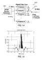
- FIG. 1is a block diagram of a WLAN system including four devices operating within the same room or area, where two of the devices are implemented according to the 802.11b standard and the other two are implemented according to the 802.11 g proposal.
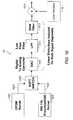
- FIG. 2is a block diagram of a mixed signal receiver implemented according to an embodiment of the present invention that may be used in either or both of the high rate devices of FIG. 1 .
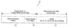
- FIG. 3is a conceptual diagram of a mixed signal packet implemented according to an embodiment of the present invention.
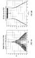
- FIGS. 4A and 4Bare graph diagrams of plots of the spectrum of the 802.11b Barker chips and the 802.11a OFDM, respectively.
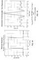
- FIGS. 5A and 5Bare graph diagrams of time domain plots of the 802.11b QPSK Barker chips and the 802.11a OFDM, respectively, illustrating that the waveforms are radically different.
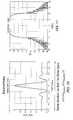
- FIG. 6Ais a graph diagram of a plot of the power spectral density (PSD) of a single sub-carrier out of the possible 64 possible sub-carriers defined in the 802.11a standard.
- PSDpower spectral density
- FIG. 6Bis a graph diagram of a plot of the composite PSD of the 52 non-zero sub-carriers used in 802.11a.
- FIG. 7Ais a graph diagram of a plot of an exemplary “brickwall” double-sided spectrum centered at 0 MHz.
- FIG. 7Bis a graph diagram of a portion of the associated infinite-duration time response corresponding to the brickwall spectrum of FIG. 7 A.
- FIG. 8is a graph diagram of a plot of an exemplary continuous-time window, which is a continuous time version of a Hanning window.
- FIG. 9is a graph diagram of a plot of the Hanning window of FIG. 8 overlayed with the portion of the infinite-duration time response corresponding to the brickwall spectrum of FIG. 7 A.
- FIG. 10is a graph diagram of a plot of the exemplary pulse p(t) resulting from the overlaying illustrated in FIG. 9 and truncated to approximately 0.8 ⁇ s.
- FIG. 11is a graph diagram of a plot of the spectral characteristics of the pulse p(t) illustrating that it is a close match to the OFDM spectrum.
- FIG. 12is a block diagram of an exemplary digital filter employed to architect a digital 22 MHz output sample rate using the continuous time pulse p(t).
- FIG. 13is a graph diagram illustrating the sampling and polyphase decomposition of the continuous time pulse p(t) using the sampling scheme of FIG. 12 .
- FIG. 14is a block diagram of another exemplary digital filter employed to architect a digital 20 MHz output sample rate using the pulse p(t).
- FIG. 15is a graph diagram illustrating the sampling and polyphase decomposition of the continuous time pulse p(t) using the sampling scheme of FIG. 14 .
- FIG. 16is a block diagram of a transmitter implemented according to an embodiment of the present invention.
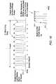
- FIG. 17is a graph diagram comparing the 11 MHz Barker chip clock versus the 20 MHz OFDM sample clock.
- FIG. 18is a conceptual graph diagram illustrating alignment of the OFDM signal portion with the last Barker word of the header of the single-carrier portion.
- FIG. 19is a graph diagram illustrating normal OFDM symbol overlap.
- FIG. 20is a graph diagram illustrating exemplary 802.11a OFDM symbol onset and termination.
- FIG. 21is a graph diagram illustrating exemplary single-carrier termination, shaped consistent with 802.11a, and OFDM onset shaped identical to 802.11 a.
- FIG. 22Ais a simplified graph diagram of a BPSK plot illustrating that BPSK incorporates both real and imaginary portions in two quadrants (1 of 2 phases).
- FIG. 22Bis a simplified graph diagram of a QPSK plot illustrating that QPSK incorporates both real and imaginary portions in all four quadrants (1 of 4 phases).
- FIG. 23is a graph diagram of a plot illustrating the phase of the last Barker word in the 802.11 g header and the relative phase of the OFDM symbol in accordance with that described in Annex G of the 802.11a standard.
- a configuration according to the present inventionreuses the equalizer information obtained during acquisition of the single-carrier portion of the signal. In this manner, no OFDM preamble is required, although it still may be present for both convenience and fine tuning.
- the present disclosuredescribes a technique for providing complete continuity between the single-carrier and OFDM (multi-carrier) segments. This continuity is provided by specifying the transmit waveform completely for both the single-carrier and OFDM segments and specifying the transition. This enables complete continuity between the two signal segments, including AGC (power), carrier phase, carrier frequency, timing and spectrum (multi-path).
- the signaldoes not have to be reacquired by the multi-path portion of the receiver since the information developed during the single-carrier portion (preamble/header) is valid and used to initiate capture of the multi-carrier portion. Maintaining and accumulating information makes the signal much more robust in the face of common interferences experience in wireless communications.
- FIG. 1is a block diagram of a wireless local area network (WLAN) system 100 operating within a particular room or area 101 , including four WLAN devices 103 , 105 , 107 and 109 ( 103 - 109 ) are located within the area 101 .
- the devices 103 and 105are implemented according to at least one of several embodiments of the present invention with the 802.11 g proposal in mind, whereas the devices 107 and 109 are implemented according to the 802.11b standard. All of the devices 103 - 109 operate in the 2.4 GHz band.
- the devices 103 - 109may be any type of wireless communication device, such as any type of computer (desktop, portable, laptop, etc.), any type of compatible telecommunication device, any type of personal digital assistant (PDA), or any other type of network device, such as printers, fax machines, scanners, hubs, switches, routers, etc. It is noted that the present invention is not limited to the 802.11 g proposal, the 802.11b standard, the 802.11a standard or the 2.4 GHz frequency band, although these standards and frequencies may be utilized in certain embodiments.
- the devices 107 and 109communicate with each other at any of the standard 802.11b rates, including 1, 2, 5.5 and 11 Mbps.
- the devices 103 and 105are mixed signal mode devices that communicate with each other at different or higher data rates using a mixed signal configuration according to any one of several embodiments, such as the standard 802.11a data rates of 6, 9, 12, 18, 24, 36, 48 or 54 Mbps.
- Alternative data rate groupsare considered herein.
- the second groupis advantageous as including two of the 802.11b standard data rates, namely 5.5 and 11 Mbps.
- the mixed signal devices 103 - 109may operate or coexist in the same area 101 without significant interference from each other, where the devices 103 , 105 communicate with each other at different or higher data rates than the 802.11b devices 107 , 109 .
- the devices 103 , 105may communicate with each other while the devices 107 , 109 may communicate with each other, but the devices 103 , 105 do not communicate with the devices 107 , 109 .
- at least one of the mixed signal devices 103 , 105is configured with a standard mode to be able to communicate with either of the devices 107 , 109 at any one or more of the standard 802.11b data rates.
- the mixed signal devices 103 , 105communicate at different or higher data rates and are incompatible with the devices 107 and 109 , so that the devices 103 - 109 are not able to coexist within the same area 101 .
- the mixed signal devices 103 , 105may be implemented to operate in the 2.4 GHz band, although other frequency bands are contemplated.
- the devices 103 and 105be able to communicate with each other without interruption or interference from either of the devices 107 and 109 .
- the present inventionsolves this problem by enabling the devices 103 and 105 to be implemented to be able to communicate with each other at different or at higher data rates while residing in a same area 101 as the 802.11b devices 107 , 109 .
- the devices 103 , 105may also communicate with either of the devices 107 , 109 at the 802.11b data rates.
- FIG. 2is a block diagram of a mixed signal receiver 201 implemented according to an embodiment of the present invention that may be used in either or both of the devices 103 , 105 .
- the incoming signalis received by an automatic gain control (AGC) 203 that adjusts receive power and provides a corresponding signal to a switch 205 .
- AGCautomatic gain control
- the switch 205initially provides the received signal to a single-carrier receiver 207 .
- the single-carrier receiver 207includes an equalizer and other circuitry that analyzes the predetermined preamble of the received signal compared to known data and “learns” the parameters associated with the multi-path medium through which the signal was propagated.
- the single-carrier receiver 207also examines the header to determine if the packet is intended for the mixed signal receiver 201 and if the packet is a mixed packet, and if so, causes the switch 205 to provide the remaining portion of the incoming signal to a multi-carrier receiver 209 .
- the headerincludes a mixed mode identifier (not shown), such as a mode bit or the like, that identifies the packet as a mixed mode packet.
- the single-carrier receiver 207determines that the packet is intended for the mixed signal receiver 201 from a destination address or the like, and determines that the packet is a mixed mode packet from the mode identifier.
- the single-carrier receiver 207continues to process the packet.
- a length fieldis also provided in the header which includes a length value that identifies the total length of the mixed mode packet.
- any deviceincluding mixed mode or legacy devices (e.g. 802.11b devices), may determine that the packet is not intended for it, and backs-off by an amount of time corresponding to the length value.
- the multi-carrier receiver 209is configured to receive the signal, which is transmitted according to OFDM or the like.
- the multi-carrier receiver 209is coupled to the single-carrier receiver 207 so that the multi-path information determined by the single-carrier receiver 207 is re-used to enable a smooth transition between the packet portions of the incoming signal.
- the AGC (power), carrier frequency, carrier phase, equalizer, and timing parameters from the single-carrier receiver 207are used by the multi-carrier receiver 209 to receive the incoming signal.
- the OFDM multi-carrier receiver 209need not re-acquire the signal, since the information used by the single-carrier receiver 207 is obtained and used.
- FIG. 3is a conceptual diagram of a mixed signal packet 301 implemented according to an embodiment of the present invention.
- the packet 301includes a Barker Preamble 303 , which is transmitted at 1 megabits per second (Mbps), followed by a Barker Header 305 , which is transmitted at 1 or 2 Mbps, followed by one or more OFDM symbols 307 incorporating payload data, which is transmitted at any selected data rate from among typical data rates of 6, 9, 12, 18, 24, 36, 48 or 54 Mbps with a selected sample rate of 20 megahertz (MHz).
- the preamble 303 and header 305are transmitted with a single carrier at the 11 MHz Quadrature Phase Shift Keying (QPSK) symbol rate (and Binary Phase Shift Keying [BPSK] is also contemplated).
- QPSKQuadrature Phase Shift Keying
- BPSKBinary Phase Shift Keying
- the transmit signalis specified for complementary code keying OFDM, or CCK-OFDM (802.11b preamble and header using Barkers [single carrier] followed by OFDM [multi-carrier]).
- the OFDM portion of the waveformcan optionally be one of several effective sample rates (e.g., 22, 20, or 18.33 MHz).
- the packet 301is shown employing the 802.11a sample rate of 20 MHz. The goal is to specify the signal so that the channel impulse response (CIR) estimate obtained on the preamble and header is reusable on the OFDM.
- CIRchannel impulse response
- a power stepmay cause legacy equipment to enter an undefined state, since they do not have knowledge of the OFDM, nor the capability to receive it.
- FIGS. 4A and 4Bare graph diagrams of plots of the spectrum of the 802.11b Barker chips and the 802.11a OFDM, respectively, in decibels (dB) versus normalized frequency (freq). Spectrum refers to center frequency, power spectral density, and frequency response.
- the 802.11b Barker chip spectrumhas a round “top” whereas the 802.11a OFDM spectrum has a flat top. The 3 dB bandwidths are also different.
- FIGS. 5A and 5Bare graph diagrams of time domain plots of the 802.11b QPSK Barker chips and the 802.11a OFDM, respectively, illustrating that the waveforms are radically different.
- FIG. 6Ais a graph diagram of a plot of the power spectral density (PSD) of a single sub-carrier out of the possible 64 possible sub-carriers defined in the 802.11a standard, in dB versus frequency.
- FIG. 6Bis a graph diagram of a plot of the composite PSD of the 52 non-zero sub-carriers used in 802.11a. The curves are plotted versus normalized frequency (nfreq) and frequency in MHz, respectively. It is desired to design a spectrum/time shaping pulse, which makes the spectrum of the single-carrier portion of the signal resemble OFDM. This pulse is made known so that the receiver is able to compensate the CIR for the OFDM portion of the packet.
- PSDpower spectral density
- the pulseis specified in continuous time, so that it is implementation independent. For digital implementations, the pulse may be sampled at any desired appropriate implementation rate.
- the signalshould provide a nearly flat spectrum in the pass-band with sufficiently steep roll-off on the band edges. It is desired that the transmit pulse be easily handled by 802.11b legacy receivers. It should have a dominant peak, therefore, with a small amount of spread in the impulse response. This allows the 802.11b receiver to lock on to this impulse response component. It is desired that the signal have a short duration to minimize complexity.
- a brickwall spectrumis essentially an idealized low-pass filter.
- FIG. 7Bis a graph diagram of a portion of the associated infinite-duration time response corresponding to the brickwall spectrum.
- a target spectrumis chosen for the single carrier system. This is done by specifying a brickwall approximation to the desired spectrum.
- a brickwall spectrumhas an infinite impulse response in the time domain (i.e., spans from +/ ⁇ infinity).
- the pulseis then truncated using a continuous-time window.
- a long enough windowis chosen to give the desired spectral characteristics while a short enough window is chosen to minimize complexity, each generally employing engineering judgment.
- FIG. 8is a graph diagram of a plot of an exemplary continuous-time window, which is a continuous time version of a Hanning window. It is appreciated that this is only one of many different window configurations that may be successfully employed to achieve desirable results.
- FIG. 9is a graph diagram of a plot of the Hanning window overlayed with the portion of the infinite-duration time response corresponding to the brickwall spectrum.
- FIG. 10is a graph diagram of a plot of the resulting exemplary pulse p(t) truncated to approximately 0.8 ⁇ s so that it is zero outside +/ ⁇ 0.4 ⁇ s. The short duration of the pulse p(t) provides low complexity.
- FIG. 9is a graph diagram of a plot of the Hanning window overlayed with the portion of the infinite-duration time response corresponding to the brickwall spectrum.
- FIG. 10is a graph diagram of a plot of the resulting exemplary pulse p(t) truncated to approximately 0.8 ⁇ s so that it is zero outside +/
- FIG. 11is a graph diagram of a plot of the spectral characteristics of the pulse p(t) illustrating that it is a close match to the OFDM spectrum.
- the spectral characteristics of the pulse p(t)include a nearly flat spectrum where OFDM is flat and a fast roll-off where OFDM rolls off.
- the continuous time pulsecan be used to construct any digital filter unambiguously and is independent of particular implementations.
- the Nyquist criteriasampling of the continuous time pulse
- the pulse p(t)is “digitized” or sampled according to the Nyquist criterion. In some embodiments, the samples are then decomposed as described further below.
- FIG. 12is a block diagram of an exemplary digital filter 1201 employed to architect a digital 22 MHz output sample rate using the continuous time pulse p(t).
- an exemplary QPSK symbol generator 1203provides an 11 MHz signal to respective inputs of each of a pair of polyphase digital filters 1205 and 1207 .
- the QPSK symbol generator 1203used as an exemplary transmitter for illustration, passes each symbol (a complex number) to both of the digital filters 1205 and 1207 at a rate of 11 MHz each.
- Each digital filter 1205 and 1207samples the input waveform and generates an output at 11 MHz.
- the digital filter taps 1205are composed of even numbered samples and the digital filter taps 1207 are composed of odd numbered samples of the pulse p(t).
- FIG. 13is a graph diagram illustrating the sampling and polyphase decomposition of the continuous time pulse p(t) (plotted versus time in microseconds, “ ⁇ s”). Since every output of every filter is used, the effective sampling rate is 22 MHz.
- FIG. 14is a block diagram of another exemplary digital filter 1401 employed to architect a digital 20 MHz output sample rate using the pulse p(t).
- an exemplary QPSK symbol generator 1403similar to the generator 1203 , provides an 11 MHz signal to respective inputs of twenty polyphase digital filters 1405 , 1407 , 1409 , . . . 1411 .
- Each digital filter 1405 - 1411generates an output at 11 MHz, so that the sampling rate is increased from 11 MHz to 220 MHz.
- Each filterconsists of the samples spaced 20 samples apart.
- Select logic 1413such as multiplexor (MUX) circuitry or the like, selects one of every 11 outputs of the polyphase digital filters 1405 - 1411 to achieve a 20 MHz sample signal. For example, for the first QPSK symbol, the respective outputs of filters 1 and 11 are used and for the second QPSK symbol, the respective outputs of filters 19 and 10 are used, etc. Also, one out of every eleven input symbols will generate 1 output sample, whereas the remaining input samples each generate two output samples.
- FIG. 15is a graph diagram illustrating the sampling and polyphase decomposition of the continuous time pulse p(t) plotted versus time. Since one out of every 11 outputs is used of the 220 MHz combined output of the filters 1405 - 1411 , the effective sampling rate is 20 MHz.
- FIG. 16is a block diagram of a transmitter 1601 implemented according to an embodiment of the present invention.
- the transmitter 1601includes an OFDM Kernel block 1603 supplying the OFDM portion of the signal to a soft switch block 1607 , which receives the 802.11b preamble and header portion from an 802.11b preamble/header Kernel block 1605 .
- the soft switch block 1607provides the 802.11 g signal to a digital to analog converter (DAC) 1609 , which provides a resulting analog signal to a low-pass filter (LPF) 1611 .
- the filtered signalis provided to a SAW filter 1613 , illustrating that linear distortions are induced on both signal segments.
- DACdigital to analog converter
- LPFlow-pass filter
- the output of the SAW filter 1613is provided to one input of a mixer 1615 , having another input which receives a local oscillator (LO) signal from a local oscillator 1617 .
- the mixer 1615asserts a mixed or combined signal at its output.
- Distortionscan be induced in the transmitter, multi-path channel and receiver.
- An obvious linear distortion in the transmitteris a SAW filter, such as the SAW filter 1613 .
- SAW filter 1613In communications systems, it is frequently assumed that linear distortions are common and (essentially) time-invariant across waveform symbols. For example, linear distortions are assumed common between the preamble/header and payload portions for both 802.11a and 802.11b communications.
- linear distortions of the transmit radioare assumed to be common to both the single-carrier segment and the multi-carrier segment. In this manner, a spectral binding requirement is imposed to allow the equalizer information and the AGC to carry over from single- to multi-carrier.
- the transmitter 1601further illustrates a sample-power matching scheme to enable the AGC information to carry over from single-carrier to multi-carrier portions of the signal.
- a sample-power matching schemeto enable the AGC information to carry over from single-carrier to multi-carrier portions of the signal.
- the average signal power output from the OFDM Kernel block 1603as shown at 1620 , be approximately the same as the average signal power output from the 802.11b preamble/header Kernel block 1605 , as shown at 1622 .
- FIG. 17is a graph diagram comparing the 11 MHz Barker chip clock shown at 1701 versus the 20 MHz OFDM sample clock shown at 1703 , both plotted versus time in ⁇ s.
- the 802.11b communication schemeuses a chip rate of 11 MHz.
- the 802.11b preamble/headeruses 11 chip Barker words, so that there are 11 chips/ ⁇ s.
- the 802.11a OFDMuses a 20 MHz sample rate.
- the 802.11b (11 MHz) and 802.11a (20 MHz) signal segmentsare aligned at the 1 MHz boundary, every 1 ⁇ s interval, illustrated by alignment epochs 1705 at each 1 ⁇ s interval.
- FIG. 17is a graph diagram comparing the 11 MHz Barker chip clock shown at 1701 versus the 20 MHz OFDM sample clock shown at 1703 , both plotted versus time in ⁇ s.
- the 802.11b communication schemeuses a chip rate of 11 MHz.
- 18is a conceptual graph diagram illustrating alignment of the OFDM signal portion with the last Barker word of the header of the single-carrier portion.
- the first chip of each Barker wordshown at 1803 , is centered on the 1 ⁇ s alignment.
- the first full 20 MHz sample of the OFDM signal, shown at 1801occurs 1 ⁇ s after the zero-phase peak of first chip of the last Barker word in the header.
- one half-scale OFDM sample, shown at 1805occurs before the full scale sample (for smoothing).
- Such transition time alignmentallows the equalizer information and the timing information to carry over between the single- and multi-phase portions of the signal.
- FIG. 19is a graph diagram illustrating normal OFDM symbol overlap.
- FIG. 20is a graph diagram illustrating exemplary 802.11a OFDM symbol onset and termination.
- FIG. 21is a graph diagram illustrating exemplary single-carrier termination, shaped consistent with 802.11a as shown at 2101 , and OFDM onset shaped identical to 802.11a, as shown at 2103 .
- the single-carrieris terminated in a controlled fashion when transitioning from single-carrier to multi-carrier. This single-carrier termination maintains the AGC at the point of transition, minimizes the signal power gap, which in turn minimizes the corruption of one signal by the other.
- the single-carrier termination of the 802.11b segmentis similar to that used for 802.11a OFDM shaping.
- 802.11aspecifies a windowing function for OFDM symbols, which is employed to define termination of single-carrier segment.
- the single-carrier signalis terminated in a predetermined window of time, such as nominally 100 nanoseconds (ns). It is not necessary to completely flush the single-carrier pulse-shaping filter.
- the resulting distortion to the last Barker word in the headeris trivial compared to the 11 chips processing gain, thermal noise and multi-path distortion.
- the terminationmay be accomplished either explicitly in the digital signal processing or by analog filtering.
- carrier frequencybe coherent for both waveform segments, achieved by using a single LO signal via the local oscillator 1617 . This allows the equalizer information to carry over.
- Carrier frequency lockmay be maintained with a phase-lock loop (PLL) circuit or the like.
- FIG. 22Ais a simplified graph diagram of a BPSK plot illustrating that BPSK incorporates both real and imaginary portions in two quadrants (1 of 2 phases).
- FIG. 22Bis a simplified graph diagram of a QPSK plot illustrating that QPSK incorporates both real and imaginary portions in all four quadrants (1 of 4 phases).
- the single-carrier signalsemploying Direct Sequence Spread Spectrum (DSSS), are fundamentally different as compared to the OFDM signal format and modulation schemes. For 802.11 g CCK-ODFM, either of these formats are re-used for the header.
- DSSSDirect Sequence Spread Spectrum
- FIG. 23is a series of graph diagrams illustrating the phase relationship between the last Barker word, rather than the last chip, in the 802.11 g header and subsequent OFDM symbol samples.
- Annex G of the 802.11a standarddescribes how to transmit an OFDM symbol including real and imaginary components.
- the arrows shown at 2301 , 2303 , 2305 and 2307illustrate the four possible phases of the last Barker word.
- the phase of the OFDM symbolis determined by the phase of the last Barker word, in that each OFDM sample is either not rotated or rotated by the same, predetermined amount based on the phase of the last Barker word.
- the arrows shown at 2302 , 2304 , 2306 and 2308represent the corresponding four relative phase shifts applied to the OFDM symbol corresponding to the Barker phase illustrated by arrows 2301 , 2303 , 2305 and 2307 , respectively.
- the phase of the OFDM symbolswill be rotated by zero degrees (not rotated, or multiplied by 1) relative to the OFDM phase as described in Annex G of the 802.11a standard.
- phase of the last Barker wordis in the second quadrant (135 degree phase rotation)
- the phase of the OFDM symbolswill be rotated by 90 degrees relative to the phase of the samples in 802.11a Annex G (i.e., multiplied by “j”
- the phase of the last Barker wordis in the third quadrant ( ⁇ 135 degree phase rotation)
- the phase of the OFDM symbolswill be rotated by 180 degrees relative to the phase of the samples in 802.11a Annex G (i.e., multiplied by “ ⁇ 1”
- the phase of the last Barker wordis in the fourth quadrant ( ⁇ 45 degree phase rotation)
- the phase of the OFDM symbolswill be rotated by ⁇ 90 degrees relative to the phase of the samples in 802.11a Annex G (i.e., multiplied by “ ⁇ j”).
- the requisite fidelity of the entire waveform behavioris established using a metric based on the fidelity requirements of the OFDM signal of the 802.11a standard.
- the requisite fidelity of the single-carrier portionis the same as the multi-carrier portion even though the single-carrier portion is typically at a reduced data rate.
- the requisite fidelity for OFDMis set by the error vector magnitude (EVM) specification, as illustrated in the following Data Rate versus EVM Table 1:
- EVMmean-squared-error
- Portions of 802.11b specification and all of the 802.11a specificationemploy a locked-oscillator requirement.
- a locked oscillator characteristicallows timing tracking information to be derived from carrier frequency and phase.
- all of the 802.11 g signalshave a symbol rate clock and carrier frequency derived from the same clock reference. It is further desired that the part-per-million (PPM) error on these two clock signals be equal.
- PPMpart-per-million
- the multi-carrier receiver 209 portion of the mixed signal receiver 201obtains the behavior of the transition from the single-carrier receiver 207 of the waveform as described herein to receive the ODFM portion of the signal.
- the carrier frequency and phaseis coherent.
- the time alignment, the signal level (AGC), and the channel impulse response (CIR)are each coherent.
- the single-carrier receiver 207determines the CIR estimate during the single-carrier portion.
- the multi-carrier receiver 209modifies the CIR estimate for the OFDM using the known pulse shape used by the single-carrier segment.
- the equalizer taps of the multi-carrier receiver 209are modified using the known pulse shape used by the transmitter during the single-carrier preamble and header.
- the multi-carrier receiver 209does not have to reacquire the OFDM portion of the signal, but uses the information obtained by the single-carrier receiver 207 along with predetermined or known information for a smooth single-carrier to multi-carrier signal transition. Also, a separate OFDM preamble/header is not necessary, although it may be employed for both convenience and fine tuning, if desired.
Landscapes
- Engineering & Computer Science (AREA)
- Signal Processing (AREA)
- Computer Networks & Wireless Communication (AREA)
- Power Engineering (AREA)
- Digital Transmission Methods That Use Modulated Carrier Waves (AREA)
- Mobile Radio Communication Systems (AREA)
Abstract
Description
| TABLE 1 |
| Data Rate versus EVM specification |
| Data Rate | EVM Spec | ||
| 6 | −5 | ||
| 9 | −8 | ||
| 12 | −10 | ||
| 18 | −13 | ||
| 24 | −16 | ||
| 36 | −19 | ||
| 48 | −22 | ||
| 54 | −25 | ||
Claims (23)
Priority Applications (17)
| Application Number | Priority Date | Filing Date | Title |
|---|---|---|---|
| US10/143,134US6754195B2 (en) | 2001-07-06 | 2002-05-10 | Wireless communication system configured to communicate using a mixed waveform configuration |
| TW091111308ATW578397B (en) | 2001-07-06 | 2002-05-28 | Wireless communication system configured to communicate using a mixed waveform configuration |
| DE10297028TDE10297028T5 (en) | 2001-07-06 | 2002-07-02 | A wireless communication system configured to communicate using a mixed waveform design |
| CNA028136632ACN1582553A (en) | 2001-07-06 | 2002-07-02 | Wireless communication system configured to communicate using a mixed waveform configuration |
| PCT/US2002/021095WO2003005652A1 (en) | 2001-07-06 | 2002-07-02 | Wireless communication system configured to communicate using a mixed waveform configuration |
| JP2003511486AJP2004537892A (en) | 2001-07-06 | 2002-07-02 | Wireless communication system for communicating using mixed waveform configuration |
| US10/191,901US7161987B2 (en) | 2001-09-26 | 2002-07-09 | Single-carrier to multi-carrier wireless architecture |
| US10/191,221US7170880B2 (en) | 2001-10-16 | 2002-07-09 | Sample rate change between single-carrier and multi-carrier waveforms |
| AU2002327719AAU2002327719A1 (en) | 2001-10-16 | 2002-09-25 | Change of sampling rate with single carrier and multicarrier waveforms |
| JP2003531706AJP2005528002A (en) | 2001-09-26 | 2002-09-25 | Single-carrier / multi-carrier wireless architecture |
| CNA028189094ACN1559129A (en) | 2001-09-26 | 2002-09-25 | Single-carrier to multi-carrier wireless architecture |
| PCT/US2002/030411WO2003028329A2 (en) | 2001-09-26 | 2002-09-25 | Single-carrier and multicarrier receiver architecture |
| DE10297220ADE10297220A1 (en) | 2001-09-26 | 2002-09-25 | Single-carrier / multi-carrier wireless architecture |
| PCT/US2002/030410WO2003034676A2 (en) | 2001-10-16 | 2002-09-25 | Change of sampling rate with single carrier and multicarrier waveforms |
| AU2002327720AAU2002327720A1 (en) | 2001-09-26 | 2002-09-25 | Single-carrier and multicarrier receiver architecture |
| TW091122012ATW567660B (en) | 2001-09-26 | 2002-09-25 | Baseband receiver, wireless radio frequency communication device, and method of generating a mixed carrier packet for radio frequency transmission |
| US12/319,707USRE43670E1 (en) | 2001-09-26 | 2009-01-09 | Single-carrier to multi-carrier wireless architecture |
Applications Claiming Priority (2)
| Application Number | Priority Date | Filing Date | Title |
|---|---|---|---|
| US30643801P | 2001-07-06 | 2001-07-06 | |
| US10/143,134US6754195B2 (en) | 2001-07-06 | 2002-05-10 | Wireless communication system configured to communicate using a mixed waveform configuration |
Related Child Applications (2)
| Application Number | Title | Priority Date | Filing Date |
|---|---|---|---|
| US10/191,221Continuation-In-PartUS7170880B2 (en) | 2001-10-16 | 2002-07-09 | Sample rate change between single-carrier and multi-carrier waveforms |
| US10/191,901Continuation-In-PartUS7161987B2 (en) | 2001-09-26 | 2002-07-09 | Single-carrier to multi-carrier wireless architecture |
Publications (2)
| Publication Number | Publication Date |
|---|---|
| US20030012160A1 US20030012160A1 (en) | 2003-01-16 |
| US6754195B2true US6754195B2 (en) | 2004-06-22 |
Family
ID=26840710
Family Applications (1)
| Application Number | Title | Priority Date | Filing Date |
|---|---|---|---|
| US10/143,134Expired - LifetimeUS6754195B2 (en) | 2001-07-06 | 2002-05-10 | Wireless communication system configured to communicate using a mixed waveform configuration |
Country Status (6)
| Country | Link |
|---|---|
| US (1) | US6754195B2 (en) |
| JP (1) | JP2004537892A (en) |
| CN (1) | CN1582553A (en) |
| DE (1) | DE10297028T5 (en) |
| TW (1) | TW578397B (en) |
| WO (1) | WO2003005652A1 (en) |
Cited By (32)
| Publication number | Priority date | Publication date | Assignee | Title |
|---|---|---|---|---|
| US20010053136A1 (en)* | 2000-06-20 | 2001-12-20 | Sten Sjoberg | Device for narrow-band communication in a multi-carrier system |
| US20030185241A1 (en)* | 2002-04-01 | 2003-10-02 | Texas Instruments Incorporated | Wireless network scheduling data frames including physical layer configuration |
| US20040001448A1 (en)* | 2002-06-28 | 2004-01-01 | Preston Shawn E. | System and method for transmitting highly correlated preambles in QAM constellations |
| US20040064592A1 (en)* | 2002-09-30 | 2004-04-01 | Takashi Ishidoshiro | Wireless Lan, method for data transmission and reception through wireless Lan, and medium storing program to control data transmission and reception |
| US20050003796A1 (en)* | 2003-03-27 | 2005-01-06 | Kyocera Corporation | Wireless telecommunication system, wireless base station, and wireless communication terminal |
| US20050052990A1 (en)* | 2003-09-10 | 2005-03-10 | Envara Ltd. | Orthogonal frequency division multiplexing error vector magnitude calibration based on separate multi-tone measurement |
| US20050058102A1 (en)* | 2003-09-15 | 2005-03-17 | Santhoff John H. | Ultra-wideband communication protocol |
| US20050058121A1 (en)* | 2003-09-15 | 2005-03-17 | John Santhoff | Ultra-wideband communication protocol |
| US20050058153A1 (en)* | 2003-09-15 | 2005-03-17 | John Santhoff | Common signaling method |
| US20050058114A1 (en)* | 2003-09-15 | 2005-03-17 | John Santhoff | Ultra-wideband communication protocol |
| US20050136933A1 (en)* | 2003-08-08 | 2005-06-23 | Intel Corporation | Method and apparatus for transmitting wireless signals on multiple frequency channels in a frequency agile network |
| US20050160181A1 (en)* | 2004-01-15 | 2005-07-21 | Samsung Electronics Co., Ltd. | Method of communications between MIMO stations |
| US20050259684A1 (en)* | 2004-05-21 | 2005-11-24 | Samsung Electronics Co., Ltd. | Wireless network and mobile stations for implementing variable bandwidth service on demand |
| US20050281241A1 (en)* | 2004-06-22 | 2005-12-22 | Webster Mark A | Legacy compatible spatial multiplexing systems and methods |
| US20060002361A1 (en)* | 2004-06-22 | 2006-01-05 | Webster Mark A | Packet processing systems and methods |
| US20060018249A1 (en)* | 2004-07-20 | 2006-01-26 | Daniel Shearer | Packet generation systems and methods |
| US7062703B1 (en)* | 2003-07-28 | 2006-06-13 | Cisco Technology, Inc | Early detection of false start-of-packet triggers in a wireless network node |
| US7236747B1 (en)* | 2003-06-18 | 2007-06-26 | Samsung Electronics Co., Ltd. (SAIT) | Increasing OFDM transmit power via reduction in pilot tone |
| US7301924B1 (en)* | 2002-07-15 | 2007-11-27 | Cisco Technology, Inc. | Media access control for MIMO wireless network |
| US20080026704A1 (en)* | 2006-07-31 | 2008-01-31 | Ntt Docomo, Inc. | Wireless transmitter, wireless receiver, wireless communication system, and wireless signal control method |
| US20080051099A1 (en)* | 2004-07-30 | 2008-02-28 | Steve Moore | Common signaling method and apparatus |
| US7356072B1 (en) | 2001-11-16 | 2008-04-08 | Marvell International, Ltd. | Antenna diversity technique for wireless communication |
| US7386074B1 (en) | 2003-10-06 | 2008-06-10 | Redpine Signals, Inc. | Digital automatic gain control method and apparatus |
| US7436878B1 (en) | 2005-05-24 | 2008-10-14 | L-3 Communications Corporation | Method and apparatus for efficient carrier bin search for a composite spreading code |
| US20090232194A1 (en)* | 2005-09-07 | 2009-09-17 | Nec Corporation | Adaptive radio/modulation apparatus, receiver apparatus, wireless communication system, and wireless communication method |
| US20090252104A1 (en)* | 2008-04-08 | 2009-10-08 | Hongyuan Zhang | Physical Layer Frame Format Design for Wideband Wireless Communications Systems |
| US7609751B1 (en) | 2005-05-24 | 2009-10-27 | L-3 Communications Corporation | Method and apparatus to initiate communications between an unknown node and an existing secure network |
| US20100008436A1 (en)* | 2008-07-08 | 2010-01-14 | Hongyuan Zhang | Physical Layer Frame Format Design for Wideband Wireless Communications Systems |
| US7760697B1 (en)* | 2005-05-24 | 2010-07-20 | L-3 Communications Corporation | Fast and long range node discovery in spread spectrum networks |
| US20110207493A1 (en)* | 2008-08-25 | 2011-08-25 | Ntt Docomo, Inc. | User apparatus, base station apparatus and communication control method |
| US8139544B1 (en)* | 2004-07-30 | 2012-03-20 | Intellectual Ventures I Llc | Pilot tone processing systems and methods |
| CN101588463B (en)* | 2004-12-17 | 2012-12-12 | 三星电子株式会社 | Digital multimedia receiver and a digital multimedia receiving method thereof |
Families Citing this family (54)
| Publication number | Priority date | Publication date | Assignee | Title |
|---|---|---|---|---|
| US7274652B1 (en) | 2000-06-02 | 2007-09-25 | Conexant, Inc. | Dual packet configuration for wireless communications |
| US6754195B2 (en) | 2001-07-06 | 2004-06-22 | Intersil Americas Inc. | Wireless communication system configured to communicate using a mixed waveform configuration |
| US7394864B2 (en) | 2001-07-06 | 2008-07-01 | Conexant, Inc. | Mixed waveform configuration for wireless communications |
| US7161987B2 (en) | 2001-09-26 | 2007-01-09 | Conexant, Inc. | Single-carrier to multi-carrier wireless architecture |
| US7170880B2 (en) | 2001-10-16 | 2007-01-30 | Conexant, Inc. | Sample rate change between single-carrier and multi-carrier waveforms |
| US7916803B2 (en) | 2003-04-10 | 2011-03-29 | Qualcomm Incorporated | Modified preamble structure for IEEE 802.11a extensions to allow for coexistence and interoperability between 802.11a devices and higher data rate, MIMO or otherwise extended devices |
| US8743837B2 (en)* | 2003-04-10 | 2014-06-03 | Qualcomm Incorporated | Modified preamble structure for IEEE 802.11A extensions to allow for coexistence and interoperability between 802.11A devices and higher data rate, MIMO or otherwise extended devices |
| US7616698B2 (en) | 2003-11-04 | 2009-11-10 | Atheros Communications, Inc. | Multiple-input multiple output system and method |
| US7542453B2 (en) | 2004-01-08 | 2009-06-02 | Sony Corporation | Wireless communication system, wireless communication apparatus, wireless communication method, and computer program |
| BRPI0418324B1 (en)* | 2004-01-08 | 2018-10-09 | Sony Corp | wireless communication system, device and method |
| US7474608B2 (en)* | 2004-01-12 | 2009-01-06 | Intel Corporation | Method for signaling information by modifying modulation constellations |
| EP1756991B1 (en)* | 2004-05-20 | 2016-09-28 | Intellectual Ventures I LLC | Cyclic diversity systems and methods |
| DK1751890T3 (en)* | 2004-05-27 | 2017-06-12 | Qualcomm Inc | MODIFIED INTRODUCTION STRUCTURE FOR IEEE 802.11A EXTENSIONS TO ENABLE CO-EXISTENCE AND INTEROPERABILITY BETWEEN 802.11A DEVICES AND HIGHER DATARATES, MIMO OR OTHER EXTENDED DEVICES |
| WO2006057677A1 (en)* | 2004-07-21 | 2006-06-01 | Conexant Systems, Inc. | Packet processing systems and methods |
| US7864659B2 (en) | 2004-08-02 | 2011-01-04 | Interdigital Technology Corporation | Quality control scheme for multiple-input multiple-output (MIMO) orthogonal frequency division multiplexing (OFDM) systems |
| FR2875358B1 (en) | 2004-09-15 | 2006-12-15 | Eads Telecom Soc Par Actions S | INSERTING A SECONDARY FLOW OF BINARY INFORMATION IN A MAIN FLOW OF SYMBOLS OF DIGITAL MODULATION |
| CN101383920A (en)* | 2004-12-17 | 2009-03-11 | 三星电子株式会社 | Digital multimedia receiver and digital multimedia receiving method thereof |
| CN101383919A (en)* | 2004-12-17 | 2009-03-11 | 三星电子株式会社 | Digital multimedia receiver and digital multimedia receiving method thereof |
| CN101383800A (en)* | 2004-12-17 | 2009-03-11 | 三星电子株式会社 | Digital multimedia receiver and digital multimedia receiving method thereof |
| CN1798283B (en)* | 2004-12-20 | 2010-11-24 | 三星电子株式会社 | Digital multimedia signal receiver and receiving method thereof |
| CN1798286A (en)* | 2004-12-20 | 2006-07-05 | 三星电子株式会社 | Digital multimedia receiver and receiving method thereof |
| US7599333B2 (en)* | 2005-02-08 | 2009-10-06 | Qualcomm Incorporated | Wireless messaging preambles allowing for beamforming and legacy device coexistence |
| US8169890B2 (en)* | 2005-07-20 | 2012-05-01 | Qualcomm Incorporated | Systems and method for high data rate ultra wideband communication |
| US7711061B2 (en)* | 2005-08-24 | 2010-05-04 | Broadcom Corporation | Preamble formats supporting high-throughput MIMO WLAN and auto-detection |
| CN1933467B (en)* | 2005-09-14 | 2010-10-06 | 中国科学院上海微系统与信息技术研究所 | Wideband single carrier/multi-carrier equalizing receiver and receiving method thereof |
| JP5065609B2 (en) | 2006-03-20 | 2012-11-07 | 株式会社エヌ・ティ・ティ・ドコモ | Base station, mobile station, and transmission path measurement signal transmission control method |
| CN101755391B (en) | 2007-07-18 | 2013-08-07 | 马维尔国际贸易有限公司 | Access point with simultaneous downlink transmission of independent data for multiple client stations |
| US8149811B2 (en) | 2007-07-18 | 2012-04-03 | Marvell World Trade Ltd. | Wireless network with simultaneous uplink transmission of independent data from multiple client stations |
| WO2009012618A1 (en)* | 2007-07-25 | 2009-01-29 | Alcatel Shanghai Bell Co., Ltd. | A method of transmitting data between a base station and a mobile station and a base station of realizing the method |
| EP2301183A1 (en)* | 2008-07-08 | 2011-03-30 | Marvell World Trade Ltd. | Physical layer frame format design for wideband wireless communications systems |
| US8982889B2 (en) | 2008-07-18 | 2015-03-17 | Marvell World Trade Ltd. | Preamble designs for sub-1GHz frequency bands |
| US20100111229A1 (en) | 2008-08-08 | 2010-05-06 | Assaf Kasher | Method and apparatus of generating packet preamble |
| US8467331B2 (en)* | 2008-09-09 | 2013-06-18 | Qualcomm Incorporated | Common mode and unified frame format |
| JP5302607B2 (en)* | 2008-09-24 | 2013-10-02 | パナソニック株式会社 | Modulation method and transmitter, OFDM modulation method and OFDM transmitter |
| US8369351B2 (en)* | 2009-04-06 | 2013-02-05 | Intel Corporation | Method and apparatus for collision avoidance |
| US9088466B2 (en) | 2009-07-23 | 2015-07-21 | Marvell World Trade Ltd. | Coexistence of a normal-rate physical layer and a low-rate physical layer in a wireless network |
| JP5503961B2 (en) | 2009-12-25 | 2014-05-28 | 株式会社デンソーアイティーラボラトリ | Observation signal processor |
| JP5936280B2 (en) | 2011-01-28 | 2016-06-22 | マーベル ワールド トレード リミテッド | Long-distance wireless LAN physical layer frame format |
| US9178745B2 (en) | 2011-02-04 | 2015-11-03 | Marvell World Trade Ltd. | Control mode PHY for WLAN |
| US9130727B2 (en) | 2011-02-04 | 2015-09-08 | Marvell World Trade Ltd. | Control mode PHY for WLAN |
| CN103765973B (en) | 2011-08-29 | 2017-11-10 | 马维尔国际贸易有限公司 | Normal speed physical layer and low rate physical layer coexisting in the wireless network |
| CN104396154B (en) | 2012-05-15 | 2018-02-23 | 马维尔国际贸易有限公司 | Fully compressed and partially compressed feedback formats for WLAN |
| US8792399B2 (en)* | 2012-07-11 | 2014-07-29 | Blackberry Limited | Phase-rotated reference signals for multiple antennas |
| JP5480411B2 (en)* | 2013-02-05 | 2014-04-23 | パナソニック株式会社 | Modulation method and transmitter, OFDM modulation method and OFDM transmitter |
| CN103546400B (en)* | 2013-05-13 | 2017-02-15 | 上海数字电视国家工程研究中心有限公司 | Single-multiple carrier signal recognizing device, method and receiver |
| KR102779905B1 (en) | 2013-09-10 | 2025-03-12 | 마벨 아시아 피티이 엘티디 | Extended guard interval for outdoor wlan |
| US10218822B2 (en) | 2013-10-25 | 2019-02-26 | Marvell World Trade Ltd. | Physical layer frame format for WLAN |
| US10194006B2 (en) | 2013-10-25 | 2019-01-29 | Marvell World Trade Ltd. | Physical layer frame format for WLAN |
| KR102384850B1 (en) | 2013-10-25 | 2022-04-08 | 마벨 아시아 피티이 엘티디. | Range extension mode for wifi |
| US11855818B1 (en) | 2014-04-30 | 2023-12-26 | Marvell Asia Pte Ltd | Adaptive orthogonal frequency division multiplexing (OFDM) numerology in a wireless communication network |
| US9923658B2 (en)* | 2014-12-23 | 2018-03-20 | Intel Corporation | Interference cancelation |
| JP6239194B2 (en) | 2015-08-07 | 2017-11-29 | 三菱電機株式会社 | TRANSMISSION DEVICE, RECEPTION DEVICE, TRANSMISSION METHOD, AND RECEPTION METHOD |
| CN107068169B (en)* | 2017-03-01 | 2019-09-27 | 中国电子科技集团公司第三十八研究所 | A system and method for generating a phase-encoded signal with arbitrarily configurable symbol sequences |
| EP3410605A1 (en) | 2017-06-02 | 2018-12-05 | Intel IP Corporation | Communication device and method for radio communication |
Citations (8)
| Publication number | Priority date | Publication date | Assignee | Title |
|---|---|---|---|---|
| US5241545A (en) | 1990-11-14 | 1993-08-31 | Motorola, Inc. | Apparatus and method for recovering a time-varying signal using multiple sampling points |
| US5425050A (en) | 1992-10-23 | 1995-06-13 | Massachusetts Institute Of Technology | Television transmission system using spread spectrum and orthogonal frequency-division multiplex |
| JP2000101623A (en) | 1998-03-19 | 2000-04-07 | Texas Instr Inc <Ti> | Communication initialization method for system using multiple carrier modulation |
| US6067391A (en) | 1998-09-02 | 2000-05-23 | The United States Of America As Represented By The Secretary Of The Air Force | Multiply periodic refractive index modulated optical filters |
| US6128276A (en) | 1997-02-24 | 2000-10-03 | Radix Wireless, Inc. | Stacked-carrier discrete multiple tone communication technology and combinations with code nulling, interference cancellation, retrodirective communication and adaptive antenna arrays |
| US6298035B1 (en)* | 1999-12-21 | 2001-10-02 | Nokia Networks Oy | Estimation of two propagation channels in OFDM |
| US6344807B1 (en) | 1999-09-24 | 2002-02-05 | International Business Machines Corporation | Packet-frame generator for creating an encoded packet frame and method thereof |
| WO2003005652A1 (en) | 2001-07-06 | 2003-01-16 | Intersil Americas Inc. | Wireless communication system configured to communicate using a mixed waveform configuration |
- 2002
- 2002-05-10USUS10/143,134patent/US6754195B2/ennot_activeExpired - Lifetime
- 2002-05-28TWTW091111308Apatent/TW578397B/ennot_activeIP Right Cessation
- 2002-07-02CNCNA028136632Apatent/CN1582553A/enactivePending
- 2002-07-02WOPCT/US2002/021095patent/WO2003005652A1/enactiveApplication Filing
- 2002-07-02JPJP2003511486Apatent/JP2004537892A/enactivePending
- 2002-07-02DEDE10297028Tpatent/DE10297028T5/ennot_activeWithdrawn
Patent Citations (9)
| Publication number | Priority date | Publication date | Assignee | Title |
|---|---|---|---|---|
| US5241545A (en) | 1990-11-14 | 1993-08-31 | Motorola, Inc. | Apparatus and method for recovering a time-varying signal using multiple sampling points |
| US5425050A (en) | 1992-10-23 | 1995-06-13 | Massachusetts Institute Of Technology | Television transmission system using spread spectrum and orthogonal frequency-division multiplex |
| US6128276A (en) | 1997-02-24 | 2000-10-03 | Radix Wireless, Inc. | Stacked-carrier discrete multiple tone communication technology and combinations with code nulling, interference cancellation, retrodirective communication and adaptive antenna arrays |
| JP2000101623A (en) | 1998-03-19 | 2000-04-07 | Texas Instr Inc <Ti> | Communication initialization method for system using multiple carrier modulation |
| US6434119B1 (en) | 1998-03-19 | 2002-08-13 | Texas Instruments Incorporated | Initializing communications in systems using multi-carrier modulation |
| US6067391A (en) | 1998-09-02 | 2000-05-23 | The United States Of America As Represented By The Secretary Of The Air Force | Multiply periodic refractive index modulated optical filters |
| US6344807B1 (en) | 1999-09-24 | 2002-02-05 | International Business Machines Corporation | Packet-frame generator for creating an encoded packet frame and method thereof |
| US6298035B1 (en)* | 1999-12-21 | 2001-10-02 | Nokia Networks Oy | Estimation of two propagation channels in OFDM |
| WO2003005652A1 (en) | 2001-07-06 | 2003-01-16 | Intersil Americas Inc. | Wireless communication system configured to communicate using a mixed waveform configuration |
Non-Patent Citations (15)
Cited By (69)
| Publication number | Priority date | Publication date | Assignee | Title |
|---|---|---|---|---|
| US20010053136A1 (en)* | 2000-06-20 | 2001-12-20 | Sten Sjoberg | Device for narrow-band communication in a multi-carrier system |
| US7023826B2 (en)* | 2000-06-20 | 2006-04-04 | Telefonaktiebolaget Lm Ericsson (Publ) | Device for narrow-band communication in a multi-carrier system |
| US8964913B1 (en) | 2001-11-16 | 2015-02-24 | Marvell International Ltd. | Apparatus and method for selecting antennas based on peak-to-average ratios of received signals |
| US8488727B1 (en) | 2001-11-16 | 2013-07-16 | Marvell International Ltd. | System and method of selecting antennas based on signal-to-noise ratios and signal quality values |
| US8243778B1 (en) | 2001-11-16 | 2012-08-14 | Marvell International Ltd. | Antenna diversity technique for wireless communication |
| US7421012B1 (en)* | 2001-11-16 | 2008-09-02 | Marvell International, Ltd. | Antenna diversity technique for wireless communication |
| US7599424B1 (en) | 2001-11-16 | 2009-10-06 | Marvell International Ltd. | Antenna diversity technique for wireless communication |
| US7356072B1 (en) | 2001-11-16 | 2008-04-08 | Marvell International, Ltd. | Antenna diversity technique for wireless communication |
| US7224704B2 (en)* | 2002-04-01 | 2007-05-29 | Texas Instruments Incorporated | Wireless network scheduling data frames including physical layer configuration |
| US20030185241A1 (en)* | 2002-04-01 | 2003-10-02 | Texas Instruments Incorporated | Wireless network scheduling data frames including physical layer configuration |
| US20040001448A1 (en)* | 2002-06-28 | 2004-01-01 | Preston Shawn E. | System and method for transmitting highly correlated preambles in QAM constellations |
| US7301924B1 (en)* | 2002-07-15 | 2007-11-27 | Cisco Technology, Inc. | Media access control for MIMO wireless network |
| US7929412B1 (en) | 2002-07-15 | 2011-04-19 | Cisco Technology, Inc. | Media access control for MIMO wireless network |
| US9236928B1 (en) | 2002-07-15 | 2016-01-12 | Cisco Technology, Inc. | Media access control for MIMO wireless network |
| US8625507B1 (en) | 2002-07-15 | 2014-01-07 | Cisco Technology, Inc. | Media access control for MIMO wireless network |
| US20040064592A1 (en)* | 2002-09-30 | 2004-04-01 | Takashi Ishidoshiro | Wireless Lan, method for data transmission and reception through wireless Lan, and medium storing program to control data transmission and reception |
| US20050003796A1 (en)* | 2003-03-27 | 2005-01-06 | Kyocera Corporation | Wireless telecommunication system, wireless base station, and wireless communication terminal |
| US20070213014A1 (en)* | 2003-06-18 | 2007-09-13 | Dan Meacham | Increasing OFDM transmit power via reduction in pilot tone |
| US7809397B2 (en)* | 2003-06-18 | 2010-10-05 | Staccato Communications, Inc. | Increasing OFDM transmit power via reduction in pilot tone |
| US7236747B1 (en)* | 2003-06-18 | 2007-06-26 | Samsung Electronics Co., Ltd. (SAIT) | Increasing OFDM transmit power via reduction in pilot tone |
| US7415661B2 (en) | 2003-07-28 | 2008-08-19 | Cisco Technology, Inc. | Early detection of false start-of-packet triggers in a wireless network node |
| US20080273536A1 (en)* | 2003-07-28 | 2008-11-06 | Keaney Richard A | Early detection of false start-of-packet triggers in a wireless network node |
| US7062703B1 (en)* | 2003-07-28 | 2006-06-13 | Cisco Technology, Inc | Early detection of false start-of-packet triggers in a wireless network node |
| US20060193277A1 (en)* | 2003-07-28 | 2006-08-31 | Keaney Richard A | Early detection of false start-of-packet triggers in a wireless network node |
| US7849391B2 (en)* | 2003-07-28 | 2010-12-07 | Cisco Technology, Inc. | Early detection of false start-of-packet triggers in a wireless network node |
| US20050136933A1 (en)* | 2003-08-08 | 2005-06-23 | Intel Corporation | Method and apparatus for transmitting wireless signals on multiple frequency channels in a frequency agile network |
| US7039412B2 (en)* | 2003-08-08 | 2006-05-02 | Intel Corporation | Method and apparatus for transmitting wireless signals on multiple frequency channels in a frequency agile network |
| US20050052990A1 (en)* | 2003-09-10 | 2005-03-10 | Envara Ltd. | Orthogonal frequency division multiplexing error vector magnitude calibration based on separate multi-tone measurement |
| US20080212651A1 (en)* | 2003-09-15 | 2008-09-04 | John Santhoff | Communication protocol |
| US20050058114A1 (en)* | 2003-09-15 | 2005-03-17 | John Santhoff | Ultra-wideband communication protocol |
| WO2005029744A3 (en)* | 2003-09-15 | 2005-11-24 | Pulse Link Inc | Ultra-wideband communication protocol |
| US20050058102A1 (en)* | 2003-09-15 | 2005-03-17 | Santhoff John H. | Ultra-wideband communication protocol |
| US20050237975A1 (en)* | 2003-09-15 | 2005-10-27 | John Santhoff | Ultra-wideband communication protocol |
| US20050058121A1 (en)* | 2003-09-15 | 2005-03-17 | John Santhoff | Ultra-wideband communication protocol |
| US20050058153A1 (en)* | 2003-09-15 | 2005-03-17 | John Santhoff | Common signaling method |
| US7339883B2 (en)* | 2003-09-15 | 2008-03-04 | Pulse-Link, Inc. | Ultra-wideband communication protocol |
| US7386074B1 (en) | 2003-10-06 | 2008-06-10 | Redpine Signals, Inc. | Digital automatic gain control method and apparatus |
| US7489652B2 (en)* | 2004-01-15 | 2009-02-10 | Samsung Electronics Co., Ltd. | Method of communications between MIMO stations |
| US20050160181A1 (en)* | 2004-01-15 | 2005-07-21 | Samsung Electronics Co., Ltd. | Method of communications between MIMO stations |
| WO2005081713A3 (en)* | 2004-02-18 | 2005-12-29 | Pulse Link Inc | Ultra-wideband communication protocol |
| US20050259684A1 (en)* | 2004-05-21 | 2005-11-24 | Samsung Electronics Co., Ltd. | Wireless network and mobile stations for implementing variable bandwidth service on demand |
| US8125946B2 (en)* | 2004-05-21 | 2012-02-28 | Samsung Electronics Co., Ltd. | Wireless network and mobile stations for implementing variable bandwidth service on demand |
| US20060002361A1 (en)* | 2004-06-22 | 2006-01-05 | Webster Mark A | Packet processing systems and methods |
| US8077592B2 (en) | 2004-06-22 | 2011-12-13 | Intellectual Ventures I Llc | Packet processing systems and methods |
| US20050281241A1 (en)* | 2004-06-22 | 2005-12-22 | Webster Mark A | Legacy compatible spatial multiplexing systems and methods |
| US8705335B2 (en) | 2004-06-22 | 2014-04-22 | Intellectual Ventures I Llc | Packet processing systems and methods |
| US7643453B2 (en) | 2004-06-22 | 2010-01-05 | Webster Mark A | Legacy compatible spatial multiplexing systems and methods |
| US7742388B2 (en) | 2004-07-20 | 2010-06-22 | Daniel Shearer | Packet generation systems and methods |
| US20060018249A1 (en)* | 2004-07-20 | 2006-01-26 | Daniel Shearer | Packet generation systems and methods |
| WO2006014648A3 (en)* | 2004-07-20 | 2009-04-09 | Conexant Systems Inc | Packet generation systems and methods |
| US20080051099A1 (en)* | 2004-07-30 | 2008-02-28 | Steve Moore | Common signaling method and apparatus |
| US8139544B1 (en)* | 2004-07-30 | 2012-03-20 | Intellectual Ventures I Llc | Pilot tone processing systems and methods |
| CN101588463B (en)* | 2004-12-17 | 2012-12-12 | 三星电子株式会社 | Digital multimedia receiver and a digital multimedia receiving method thereof |
| US7760697B1 (en)* | 2005-05-24 | 2010-07-20 | L-3 Communications Corporation | Fast and long range node discovery in spread spectrum networks |
| US7609751B1 (en) | 2005-05-24 | 2009-10-27 | L-3 Communications Corporation | Method and apparatus to initiate communications between an unknown node and an existing secure network |
| US7436878B1 (en) | 2005-05-24 | 2008-10-14 | L-3 Communications Corporation | Method and apparatus for efficient carrier bin search for a composite spreading code |
| US7961800B2 (en)* | 2005-09-07 | 2011-06-14 | Nec Corporation | Adaptive radio/modulation apparatus, receiver apparatus, wireless communication system, and wireless communication method |
| US20090232194A1 (en)* | 2005-09-07 | 2009-09-17 | Nec Corporation | Adaptive radio/modulation apparatus, receiver apparatus, wireless communication system, and wireless communication method |
| US20080026704A1 (en)* | 2006-07-31 | 2008-01-31 | Ntt Docomo, Inc. | Wireless transmitter, wireless receiver, wireless communication system, and wireless signal control method |
| US7941170B2 (en) | 2006-07-31 | 2011-05-10 | Ntt Docomo, Inc. | Wireless transmitter, wireless receiver, wireless communication system, and wireless signal control method |
| US20130114764A1 (en)* | 2008-04-08 | 2013-05-09 | Marvell World Trade Ltd. | Physical Layer Frame Format Design for Wideband Wireless Communications Systems |
| US20090252104A1 (en)* | 2008-04-08 | 2009-10-08 | Hongyuan Zhang | Physical Layer Frame Format Design for Wideband Wireless Communications Systems |
| US8358668B2 (en)* | 2008-04-08 | 2013-01-22 | Marvell World Trade Ltd. | Physical layer frame format design for wideband wireless communications systems |
| US8902798B2 (en)* | 2008-04-08 | 2014-12-02 | Marvell World Trade Ltd. | Physical layer frame format design for wideband wireless communications systems |
| US8441968B2 (en)* | 2008-07-08 | 2013-05-14 | Marvell World Trade Ltd. | Physical layer frame format design for wideband wireless communications systems |
| US8605635B2 (en) | 2008-07-08 | 2013-12-10 | Marvell World Trade Ltd. | Physical layer frame format design for wideband wireless communications systems |
| US20100008436A1 (en)* | 2008-07-08 | 2010-01-14 | Hongyuan Zhang | Physical Layer Frame Format Design for Wideband Wireless Communications Systems |
| US8868122B2 (en)* | 2008-08-25 | 2014-10-21 | Ntt Docomo, Inc. | User apparatus, base station apparatus and communication control method |
| US20110207493A1 (en)* | 2008-08-25 | 2011-08-25 | Ntt Docomo, Inc. | User apparatus, base station apparatus and communication control method |
Also Published As
| Publication number | Publication date |
|---|---|
| WO2003005652A1 (en) | 2003-01-16 |
| US20030012160A1 (en) | 2003-01-16 |
| TW578397B (en) | 2004-03-01 |
| CN1582553A (en) | 2005-02-16 |
| DE10297028T5 (en) | 2004-07-22 |
| JP2004537892A (en) | 2004-12-16 |
Similar Documents
| Publication | Publication Date | Title |
|---|---|---|
| US6754195B2 (en) | Wireless communication system configured to communicate using a mixed waveform configuration | |
| US8085874B2 (en) | Mixed waveform configuration for wireless communications | |
| US7161987B2 (en) | Single-carrier to multi-carrier wireless architecture | |
| US7170880B2 (en) | Sample rate change between single-carrier and multi-carrier waveforms | |
| US8576782B2 (en) | Baseband recovery in wireless networks, base transceiver stations, and wireless networking devices | |
| KR20100102167A (en) | Imbalance compensation for direct conversion communication systems | |
| US8477594B2 (en) | Backward-compatible long training sequences for wireless communication networks | |
| JP4254245B2 (en) | Communication device | |
| KR100641067B1 (en) | A transceiver and method for communicating with a second transceiver, and a wireless telephone system | |
| Canet et al. | Time synchronization for the IEEE 802.11 a/g WLAN standard | |
| Shenping et al. | Pilot-symbol-aided frequency offset estimation and correction for OFDM system | |
| US8665788B1 (en) | Phy device preamble formatting SUWs, inverse SUWs, sync, and tone | |
| HK1071482A (en) | Single-carrier to multi-carrier wireless architecture | |
| Nolan et al. | OFDM/Flash-OFDMࡊ re-configurable transceivers using general purpose processors | |
| MXPA99012057A (en) | Transceiver prerotation based on carrier offset |
Legal Events
| Date | Code | Title | Description |
|---|---|---|---|
| AS | Assignment | Owner name:INTERSIL AMERICAS INC., CALIFORNIA Free format text:ASSIGNMENT OF ASSIGNORS INTEREST;ASSIGNORS:WEBSTER, MARK A.;SEALS, MICHAEL J.;REEL/FRAME:012895/0470 Effective date:20020508 | |
| STCF | Information on status: patent grant | Free format text:PATENTED CASE | |
| AS | Assignment | Owner name:GLOBESPAN VIRATA, INC.,NEW JERSEY Free format text:ASSIGNMENT OF ASSIGNORS INTEREST;ASSIGNOR:INTERSIL CORPORATION;REEL/FRAME:016561/0040 Effective date:20030715 Owner name:GLOBESPANVIRATA, INC.,NEW JERSEY Free format text:ASSIGNMENT OF ASSIGNORS INTEREST;ASSIGNOR:INTERSIL CORPORATION;REEL/FRAME:016561/0550 Effective date:20030715 Owner name:GLOBESPANVIRATA, INC., NEW JERSEY Free format text:ASSIGNMENT OF ASSIGNORS INTEREST;ASSIGNOR:INTERSIL CORPORATION;REEL/FRAME:016561/0550 Effective date:20030715 Owner name:GLOBESPAN VIRATA, INC., NEW JERSEY Free format text:ASSIGNMENT OF ASSIGNORS INTEREST;ASSIGNOR:INTERSIL CORPORATION;REEL/FRAME:016561/0040 Effective date:20030715 | |
| AS | Assignment | Owner name:CONEXANT, INC.,NEW JERSEY Free format text:CHANGE OF NAME;ASSIGNOR:GLOBESPANVIRATA, INC.;REEL/FRAME:016937/0061 Effective date:20040528 Owner name:CONEXANT, INC., NEW JERSEY Free format text:CHANGE OF NAME;ASSIGNOR:GLOBESPANVIRATA, INC.;REEL/FRAME:016937/0061 Effective date:20040528 | |
| AS | Assignment | Owner name:BANK OF NEW YORK TRUST COMPANY, N.A.,ILLINOIS Free format text:SECURITY INTEREST;ASSIGNOR:CONEXANT, INC.;REEL/FRAME:018545/0298 Effective date:20061113 Owner name:BANK OF NEW YORK TRUST COMPANY, N.A., ILLINOIS Free format text:SECURITY INTEREST;ASSIGNOR:CONEXANT, INC.;REEL/FRAME:018545/0298 Effective date:20061113 | |
| AS | Assignment | Owner name:GLOBESPANVIRATA, INC.,NEW JERSEY Free format text:ASSIGNMENT OF ASSIGNORS INTEREST;ASSIGNORS:INTERSIL CORPORATION;INTERSIL AMERICAS, INC.;REEL/FRAME:018826/0475 Effective date:20030715 Owner name:GLOBESPANVIRATA, INC., NEW JERSEY Free format text:ASSIGNMENT OF ASSIGNORS INTEREST;ASSIGNORS:INTERSIL CORPORATION;INTERSIL AMERICAS, INC.;REEL/FRAME:018826/0475 Effective date:20030715 | |
| FPAY | Fee payment | Year of fee payment:4 | |
| REMI | Maintenance fee reminder mailed | ||
| AS | Assignment | Owner name:GLOBESPANVIRATA, INC., NEW JERSEY Free format text:CONFIRMATORY ASSIGNMENT;ASSIGNORS:INTERSIL CORPORATION;INTERSIL AMERICAS, INC.;REEL/FRAME:021450/0637 Effective date:20080827 Owner name:GLOBESPANVIRATA, INC.,NEW JERSEY Free format text:CONFIRMATORY ASSIGNMENT;ASSIGNORS:INTERSIL CORPORATION;INTERSIL AMERICAS, INC.;REEL/FRAME:021450/0637 Effective date:20080827 | |
| AS | Assignment | Owner name:CONEXANT, INC., CALIFORNIA Free format text:RELEASE BY SECURED PARTY;ASSIGNOR:BANK OF NEW YORK MELLON TRUST COMPANY, N.A. (FORMERLY, BANK OF NEW YORK TRUST COMPANY, N.A.);REEL/FRAME:021731/0845 Effective date:20081017 Owner name:CONEXANT, INC.,CALIFORNIA Free format text:RELEASE BY SECURED PARTY;ASSIGNOR:BANK OF NEW YORK MELLON TRUST COMPANY, N.A. (FORMERLY, BANK OF NEW YORK TRUST COMPANY, N.A.);REEL/FRAME:021731/0845 Effective date:20081017 | |
| AS | Assignment | Owner name:XOCYST TRANSFER AG L.L.C., DELAWARE Free format text:ASSIGNMENT OF ASSIGNORS INTEREST;ASSIGNOR:CONEXANT, INC.;REEL/FRAME:022043/0591 Effective date:20081016 Owner name:XOCYST TRANSFER AG L.L.C.,DELAWARE Free format text:ASSIGNMENT OF ASSIGNORS INTEREST;ASSIGNOR:CONEXANT, INC.;REEL/FRAME:022043/0591 Effective date:20081016 | |
| FEPP | Fee payment procedure | Free format text:PAYOR NUMBER ASSIGNED (ORIGINAL EVENT CODE: ASPN); ENTITY STATUS OF PATENT OWNER: LARGE ENTITY | |
| AS | Assignment | Owner name:INTELLECTUAL VENTURES I LLC, DELAWARE Free format text:MERGER;ASSIGNOR:XOCYST TRANSFER AG L.L.C.;REEL/FRAME:026637/0603 Effective date:20110718 | |
| FPAY | Fee payment | Year of fee payment:8 | |
| FEPP | Fee payment procedure | Free format text:PAYER NUMBER DE-ASSIGNED (ORIGINAL EVENT CODE: RMPN); ENTITY STATUS OF PATENT OWNER: LARGE ENTITY Free format text:PAYOR NUMBER ASSIGNED (ORIGINAL EVENT CODE: ASPN); ENTITY STATUS OF PATENT OWNER: LARGE ENTITY | |
| IPR | Aia trial proceeding filed before the patent and appeal board: inter partes review | Free format text:TRIAL NO: IPR2014-00553 Opponent name:MARVELL SEMICONDUCTOR, INC. Effective date:20140327 Free format text:TRIAL NO: IPR2014-00552 Opponent name:MARVELL SEMICONDUCTOR, INC. Effective date:20140327 | |
| FPAY | Fee payment | Year of fee payment:12 | |
| IPRC | Trial and appeal board: inter partes review certificate | Kind code of ref document:K1 Free format text:INTER PARTES REVIEW CERTIFICATE; TRIAL NO. IPR2014-00552, MAR. 27, 2014; TRIAL NO. IPR2014-00553, MAR. 27, 2014INTER PARTES REVIEW CERTIFICATE FOR PATENT 6,754,195, ISSUED JUN. 22, 2004, APPL. NO. 10/143,134, MAY 10, 2002INTER PARTES REVIEW CERTIFICATE ISSUED FEB. 9, 2018 Effective date:20180209 |