US6752967B2 - Stackable aliquot vessel array - Google Patents
Stackable aliquot vessel arrayDownload PDFInfo
- Publication number
- US6752967B2 US6752967B2US10/037,512US3751202AUS6752967B2US 6752967 B2US6752967 B2US 6752967B2US 3751202 AUS3751202 AUS 3751202AUS 6752967 B2US6752967 B2US 6752967B2
- Authority
- US
- United States
- Prior art keywords
- array
- base plate
- aliquot vessel
- longer
- aliquot
- Prior art date
- Legal status (The legal status is an assumption and is not a legal conclusion. Google has not performed a legal analysis and makes no representation as to the accuracy of the status listed.)
- Expired - Fee Related, expires
Links
Images


Classifications
- B—PERFORMING OPERATIONS; TRANSPORTING
- B01—PHYSICAL OR CHEMICAL PROCESSES OR APPARATUS IN GENERAL
- B01L—CHEMICAL OR PHYSICAL LABORATORY APPARATUS FOR GENERAL USE
- B01L3/00—Containers or dishes for laboratory use, e.g. laboratory glassware; Droppers
- B01L3/50—Containers for the purpose of retaining a material to be analysed, e.g. test tubes
- B01L3/508—Containers for the purpose of retaining a material to be analysed, e.g. test tubes rigid containers not provided for above
- B01L3/5085—Containers for the purpose of retaining a material to be analysed, e.g. test tubes rigid containers not provided for above for multiple samples, e.g. microtitration plates
- B—PERFORMING OPERATIONS; TRANSPORTING
- B01—PHYSICAL OR CHEMICAL PROCESSES OR APPARATUS IN GENERAL
- B01L—CHEMICAL OR PHYSICAL LABORATORY APPARATUS FOR GENERAL USE
- B01L2200/00—Solutions for specific problems relating to chemical or physical laboratory apparatus
- B01L2200/02—Adapting objects or devices to another
- B01L2200/025—Align devices or objects to ensure defined positions relative to each other
- B—PERFORMING OPERATIONS; TRANSPORTING
- B01—PHYSICAL OR CHEMICAL PROCESSES OR APPARATUS IN GENERAL
- B01L—CHEMICAL OR PHYSICAL LABORATORY APPARATUS FOR GENERAL USE
- B01L2300/00—Additional constructional details
- B01L2300/08—Geometry, shape and general structure
- B01L2300/0809—Geometry, shape and general structure rectangular shaped
- B01L2300/0829—Multi-well plates; Microtitration plates
- G—PHYSICS
- G01—MEASURING; TESTING
- G01N—INVESTIGATING OR ANALYSING MATERIALS BY DETERMINING THEIR CHEMICAL OR PHYSICAL PROPERTIES
- G01N35/00—Automatic analysis not limited to methods or materials provided for in any single one of groups G01N1/00 - G01N33/00; Handling materials therefor
- G01N35/02—Automatic analysis not limited to methods or materials provided for in any single one of groups G01N1/00 - G01N33/00; Handling materials therefor using a plurality of sample containers moved by a conveyor system past one or more treatment or analysis stations
- G01N35/04—Details of the conveyor system
- G01N2035/0401—Sample carriers, cuvettes or reaction vessels
- G01N2035/0418—Plate elements with several rows of samples
- G01N2035/0422—Plate elements with several rows of samples carried on a linear conveyor
- G01N2035/0424—Two or more linear conveyors
- G—PHYSICS
- G01—MEASURING; TESTING
- G01N—INVESTIGATING OR ANALYSING MATERIALS BY DETERMINING THEIR CHEMICAL OR PHYSICAL PROPERTIES
- G01N35/00—Automatic analysis not limited to methods or materials provided for in any single one of groups G01N1/00 - G01N33/00; Handling materials therefor
- G01N35/02—Automatic analysis not limited to methods or materials provided for in any single one of groups G01N1/00 - G01N33/00; Handling materials therefor using a plurality of sample containers moved by a conveyor system past one or more treatment or analysis stations
- G01N35/04—Details of the conveyor system
- G01N2035/0401—Sample carriers, cuvettes or reaction vessels
- G01N2035/0418—Plate elements with several rows of samples
- G01N2035/0425—Stacks, magazines or elevators for plates
- G—PHYSICS
- G01—MEASURING; TESTING
- G01N—INVESTIGATING OR ANALYSING MATERIALS BY DETERMINING THEIR CHEMICAL OR PHYSICAL PROPERTIES
- G01N35/00—Automatic analysis not limited to methods or materials provided for in any single one of groups G01N1/00 - G01N33/00; Handling materials therefor
- G01N35/02—Automatic analysis not limited to methods or materials provided for in any single one of groups G01N1/00 - G01N33/00; Handling materials therefor using a plurality of sample containers moved by a conveyor system past one or more treatment or analysis stations
- G01N35/04—Details of the conveyor system
- G01N2035/0401—Sample carriers, cuvettes or reaction vessels
- G01N2035/0427—Sample carriers, cuvettes or reaction vessels nestable or stockable
Definitions
- the present inventionrelates to a method and apparatus for automatically processing a patient's biological fluids such as urine, blood serum, plasma, cerebrospinal fluid and the like.
- the present inventionprovides a stackable vessel for containing a plurality of liquid aliquot portions of patient samples in individual test wells.
- Various types of tests related to patient diagnosis and therapycan be performed by analysis assays of a sample of a patient's infections, bodily fluids or abscesses for an analyte of interest.
- patient samplesare typically liquids placed in sample vials, are extracted from the vials, combined with various reagents in special reaction vessels or tubes, incubated, and analyzed to aid in treatment of the patient.
- one or two assay reagentsare added at separate times to a liquid sample having a known concentration, the sample-reagent combination is mixed and incubated. Interrogating measurements, turbidimetric or fluorometric or absorption readings or the like, are made to ascertain end-point or rate values from which an amount of analyte may be determined, using well-known calibration techniques.
- An important contributor to maintaining a high efficiency in throughput of patient samplesis the ability to quickly and securely introduce a plurality of samples to the sample testing portion of an analyzer.
- Patient samplesare typically held in a container such as a sample cup, a primary tube, or any other suitable container and may be open at its top or closed with a stopper or lid or the like at its top.
- the containersmay then be placed into a sample rack adapted to support multiple sample containers generally in an upright orientation.
- the sample rackis usually placed by an operator in an input portion of the analyzer and then moved automatically moved by the analyzer to a location where a portion of the liquid patient sample, hereinafter described as a aliquot, is extracted, usually by aspiration using a hollow, needle like probe from the sample container for testing in the analyzer. Afterwards, the aliquot may be dispensed directly into a sample test vessel or into an interim aliquot vessel prior to a later transfer into a sample test vessel.
- an aliquot vessel of small physical size, of low cost and with features permitting it to be reliably handled by automated devicesIt is particularly desirable that such an aliquot vessel be able to be transported in a one-dimension linear plane on-board an analyzer so as to eliminate the necessity and expense of two-directional handling means. It is further desirable that such an aliquot vessel be capable of easily being loaded by an operator onto an analyzer, ideally being loaded from multiple vessel put-ups. It is even further desirable that such an aliquot vessel comprise a plurality of individual aliquot wells so that a single aliquot vessel accommodate a large number of different samples, for example in an array of aliquot vessels.
- U.S. Pat. No. 6,190,617provides for a test sample container including an upper skirt and a body having a reservoir for receipt of the test sample.
- the segmentincludes a base, a frame, and a handle.
- the framehas a shelf for which the upper skirt of the test sample container rests on, and has openings for receipt of the body of the sample container.
- the carouselhas a carousel trough for receipt of the base of the sample container segment, and has a plurality of alignment pins disposed in the carousel trough.
- the base of the sample container segmenthas a circular slot and an elongated slot for receiving the alignment pins and positioning the sample container segment relative to the carousel.
- the present inventionprovides a aliquot vessel array adapted with a plurality of individual sample aliquot wells and capable of being attached one atop another in a secure stack.
- the sample aliquot wellsare designed to minimize so-called “dead sample volume” inaccessible by typical aspiration means.
- a number of stacked aliquot vessel arraysmay be simultaneously loaded by an operator into a elevator-like storage unit on an analyzer and dispensed in a singulated stream onto a sampling track as required by the analyzer.
- Handling featuresare designed into the aliquot vessel array to ensure safe and reliable movement between the storage unit and linear sampling tracks where sample is originally dispensed into individual wells and later aspirated therefrom for sample liquid analysis.
- the aliquot vessel arrayis typically covered with an evaporation and protection layer and further includes alignment features so that multiple aspirations may be made from single punctures through the protection layer.
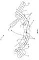
- FIG. 1is a schematic plan view of an automated analyzer in which the present invention may be used to advantage
- FIG. 1Ais an enlarged schematic plan view of a portion of the analyzer of FIG. 1;
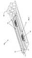
- FIG. 2is a perspective elevation view of an automated aliquot vessel array storage and handling unit integrated with a sampling track in which the present invention may be used to advantage;
- FIG. 3is a perspective elevation view of the sampling track of FIG. 2 illustrating an entry point for aliquot vessel arrays provided by the present invention into the sampling track;
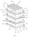
- FIG. 4is perspective elevation view of four aliquot vessel arrays of the present invention, secured together into a single stack;
- FIG. 5is front elevation view of the single stack of four aliquot vessel arrays of the present invention seen in FIG. 4;
- FIG. 6is a is front elevation view of a single aliquot vessel array of the present invention.
- FIG. 7is a plan view of a single aliquot vessel array of the present invention.
- FIG. 7Ais a sectional view of a single aliquot vessel array of the present invention.
- FIG. 8is an plan view of an alternate embodiment of the aliquot vessel array of the present invention.
- FIG. 8Ais a sectional view of the aliquot vessel array of the present invention.
- FIGS. 9A-Eare schematic views of the transferring of a single aliquot vessel array of the present invention from the storage and handling unit of FIG. 2 to the sampling track of FIG. 3 .
- FIG. 1, taken with FIG. 1A,shows schematically the elements of a conventional automatic chemical analyzer 10 in which the present invention may be advantageously practiced.
- Analyzer 10comprises a reaction carousel 12 supporting a outer cuvette circle 14 of cuvette ports 72 and 73 and an inner cuvette circle 16 of cuvette ports 74 , the outer cuvette circle 14 and inner cuvette circle 16 being separated by a open groove 18 .
- Cuvette ports 72 , 73 and 74are adapted to receive a plurality of reaction cuvettes 19 typically formed as small, flat walled, U-shaped containers with an open central reaction portion closed at the bottom and with an opening at the top of the cuvettes 19 to allow the addition of reagent and sample liquids.
- Reaction carousel 12is rotatable using stepwise movements in a constant direction at a constant velocity, the stepwise movements being separated by a constant dwell time during which dwell time, carousel 12 is maintained stationary and an assay device located proximate carousel 12 may operate on an assay mixture contained within a cuvette 19 .
- Three temperature-controlled reagent storage areas 20 , 22 and 24each store a plurality of reagent cartridges 21 , cartridges 21 , for example being a multi-compartmented reagent container like those described in U.S. Pat. No. 4,720,374, sold under the tradename FLEX® reagent cartridge by Dade Behring Inc, Deerfield, Ill., and containing reagents as necessary to perform a given assay.
- a selectively-opened lidcovers each of reagent storage areas 20 , 22 and 24 to allow access to cartridges 21 ; for simplicity, only one reagent cartridge 21 is schematically illustrated in FIG.
- reagent storage area 24As disposed beneath a cut out portion of reagent storage area 24 , however similar reagent cartridges 21 are disposed within reagent storage areas 20 and 22 .
- Shuttle means(not shown) move individual cartridges 21 to probe access ports.
- Storage areas 20 and 22may be conveniently located external to the circumference of outer cuvette circle 14 and reagent storage area 24 may be conveniently located internal to the circumference of inner cuvette circle 16 .
- a clinical analyzer 10 like those on which the present invention may be performedhas a plurality of conventional assay operation stations disposed proximate carousel 12 and at which are positioned individual computer controlled electromechanical devices, such as sensors, reagent add stations, mixing stations, and the like, as required to perform the myriad of actions required in well known clinical assays.
- individual computer controlled electromechanical devicessuch as sensors, reagent add stations, mixing stations, and the like, as required to perform the myriad of actions required in well known clinical assays.
- Such devices and their operationare well known in the art and need not be described herein. See for example, U.S. Pat. Nos. 5,876,668, 5,575,976 and 5,482,861 and the references cited therein.
- An indexing drive for the reaction carouselmoves the reaction vessels in the constant direction a predetermined numbers of incremental steps.
- the length of the circumference of cuvette circle 14 , the separation distance between cuvette ports 72 , 73 and 74 , the number of cuvette ports 72 , 73 and 74 , and the number of increments per indexingare selected so that any given cuvette ports 72 , 73 or 74 returns to its original starting position after a fixed number of incremental steps.
- a number of liquid aspiration and dispense arms 30 , 34 , and 36are located proximate the reagent storage areas 20 , 22 and 24 and controlled by a programmed computer 13 , preferably a microprocessor based central processing unit (CPU) to control all activities of analyzer 10 according to pre-programmed software, firmware, or hardware commands or circuits.
- a programmed computer 13preferably a microprocessor based central processing unit (CPU) to control all activities of analyzer 10 according to pre-programmed software, firmware, or hardware commands or circuits.
- Cuvette load and unload stations 60 and 62are positioned proximate outer cuvette carousel 14 and are conventionally adapted to load cuvettes 19 into cavities 72 , 73 and 74 seen in FIG. 1A formed in both outer cuvette carousel 14 and inner carousel 16 using for example a translatable robotic clamp 63 .
- Conventional sample processing devices, or stations 17are positioned at selected circumferential locations about the reaction carousel 12 in order to access reaction vessels 19 .
- Stations 17are adapted to provide, among other processing steps, for mixing together of the sample liquid and the reagent liquid contained in a cuvette 19 , for washing the sample liquid and the reagent liquid contained in a cuvette 19 , and for magnetic separation of tagged magnetic particles from free tags or reagent liquid contained in a cuvette 19 .
- Incoming sample specimens to be testedare transported by a sample tube rack transport system 40 described in co-pending application Ser. No.: 9/992,917, assigned to the assignee of the present invention and after aspiration into aliquot vessel arrays 102 , may be maintained within analyzer 10 inside an environmental chamber 44 described in co-pending application Ser. No. 09/827,045 assigned to the assignee of the present invention.
- Specimensare typically contained in sample containers or tubes 41 supported in sample tube racks 42 and are identified by reading bar coded indicia on sample tubes 41 using a conventional bar code reader to determine, optionally among other items, a patient's identity, the tests to be performed, if a sample aliquot is desired to be retained inside environmental chamber 44 and if so, for what period of time.
- a sampling arm 46supports a conventional liquid sampling probe 47 and is rotatably mounted so that movement of sampling arm 46 describes a line intersecting the sample tube transport system 40 and an aliquot vessel array transport system 100 adapted to transport aliquot vessel arrays 102 from an aliquot vessel array storage and handling unit 104 to a pair of conventional sample/reagent aspiration and dispense arms 50 and 52 located proximate reaction carousel 12 .
- Sampling arm 46is operable to aspirate liquid sample from sample tubes 41 and to dispense a liquid sample or an aliquot portion of the sample, into one or more of a plurality of wells 128 in aliquot vessel arrays 102 , depending on the quantity of sample required to perform the requisite assays and to provide for a sample aliquot to be retained by analyzer 10 within environmental chamber 44 .
- aliquot vessel array transport system 100After sample has been dispensed into cuvettes, aliquot vessel array transport system 100 returns aliquot vessel arrays 102 to the aliquot vessel array storage and handling unit 104 ; a separate transport system (not shown, but located beneath aliquot vessel array transport system 100 ) removes aliquot vessel arrays 102 therefrom and deposits arrays 102 into storage compartment 44 .
- Various assay analyzing means 70may be located proximate outer cuvette carousel 14 and are adapted to measure light absorbence in or emission from cuvettes 15 at various wavelengths, from which the presence of analyte in the sample liquid may be determined using well-known analytical techniques.
- Means 70typically comprise conventional photometric, fluorometric or luminescent measuring devices adapted to perform an interrogating measurement at any convenient time interval during which reaction carousel 12 is stationary.
- Drive meansare provided for independently rotating outer reaction carousel 12 about an axis, the drive means typically comprising gear teeth disposed on the carousel 12 and interlacing with pinion gears mounted on the shaft of a motor.
- the drive meansmay be of conventional design and are not illustrated.
- Analyzer 10is controlled by computer 13 based on software written in a machine language, like that used on the Dimension® clinical chemistry analyzer sold by Dade Behring Inc, of Deerfield, Ill., and widely used by those skilled in the art of computer-based electromechanical control programming.
- automated aliquot vessel array storage and handling unit 104is disposed proximate aliquot vessel array transport system 100 and is adapted in a manner described hereinafter so that aliquot vessel arrays 102 may be automatically transferred from a vertically translatable array elevator 106 from any of three aliquot vessel array inventory shafts 105 within aliquot vessel array storage unit 104 onto one of several pairs of parallel aligned aliquot vessel array sampling tracks 107 .
- Aliquot vessel arrays 102are mounted within aliquot vessel array storage unit 104 between pairs of storage tracks 103 having flared open ends 101 suitable for discharging and receiving an aliquot vessel array 102 , described later in conjunction with FIG. 9 .
- Two aliquot vessel arrays 102are seen located between a pair of sampling tracks 107 .
- the lengthwise positioning of an aliquot vessel array 102 between sampling tracks 107is provided by a motor-driven dolly 110 independently moveable in either direction within a pair of sampling tracks 107 , the dolly 110 being connected for example by a thread-screw or ladder chain (not shown) to an independently operable stepping motor 108 (see FIG. 3 ).
- Each dolly 110has a protruding and downwardly projecting finger-latch 112 adapted to secure an aliquot vessel array 102 via a zero-backlash feature described later.
- the ends of tracks 107 opposite from motors 108are open and as seen in FIG. 3, terminate with a set of flared open ends 114 suitable for receiving an aliquot vessel array 102 , described later in conjunction with FIG. 9 .
- FIG. 4illustrates a number of the important features found in the aliquot vessel array 102 of the present invention. As seen therein, a number of aliquot vessel arrays 102 may be snapped together one atop another shown as a mutually aligned vertical stack of four aliquot vessel arrays 102 .
- Each aliquot vessel array 102comprises an orthogonal base plate 116 having a pair of upwardly extending and mutually parallel first and second side walls 118 and 119 extending lengthwise along a longer orthogonal edge 120 of the base plate 116 , the side walls 118 and 119 positioned inside the outer boundary of base plate 116 and having a length shorter than the longer orthogonal edge 120 so that a longer perimeter portion 122 remains along the outermost portions of base plate 116 along the longer orthogonal edge 120 and a shorter perimeter portion 124 remains along the outermost portions of base plate 116 along a shorter front orthogonal edge 126 of the base plate 116 .
- a shorter rear orthogonal edge 127 of the base plate 116may be seen in the plan view of aliquot vessel array 102 in FIG. 7 .
- An optional recessed “billboard” portion 99may be formed in either of the first and second side walls 118 and 119 in order to frame an conventional barcode identifying indicia for the aliquot vessel array 102 .
- An ordered array of open wells 128is further formed on base plate 116 extending upwardly therefrom and confined between the pair of parallel side walls 118 and 119 .
- the parallel side walls 118are attached to the array of open wells 128 by a number of notched side flanges 121 best seen in FIG. 6 having a notch 125 adapted to mate with a foot section 138 of a rail 136 .
- a pair of parallel rails 136extend approximately the full length of the longer orthogonal edges 120 of base plate 116 and depend downwardly from the lower surfaces 115 of the base plate 116 proximate the longer orthogonal edges 120 .
- base plate 116has dimensions about 5 cm in width and 7.5 cm in length, side walls 118 are about 3-4 cm in length centered along the longer orthogonal edge 120 of the base plate 116 and extend about 1.1 cm upwardly from base plate 116 .
- Wells 128are about 0.6 cm in diameter, extend about 2 cm above base plate 116 and are about 60 in number in the embodiment described.
- aliquot vessel arrays 102may be formed of low cost plastic material in large quantities using well known plastic molding operations and may be disposed after a single use without significantly adding to the expense of operation of analyzer 10 ; furthermore, the use of disposable aliquot vessel arrays 102 eliminates the possibility of sample cross-contamination created when sample aliquot holders are washed and re-used with different patient samples.
- FIGS. 4 and 5shows how a number of aliquot vessel arrays 102 may be stacked atop one another by mating the notched side flanges 121 with the foot sections 138 of parallel rails 136 along the longer orthogonal edges 120 of base plate 116 .
- FIG. 5in particular shows four aliquot vessel arrays 102 snapped atop one another into a single stack.
- the purpose of this snap-together feature of the aliquot vessel array 102 of the present inventionis to facilitate the loading by an operator of a number of aliquot vessel arrays 102 into the aliquot vessel array storage chutes 105 of vessel array storage and handling unit 104 as seen in FIG. 2 .
- FIG. 6is an enlarged front elevation view showing how the foot section 138 of rail 136 of the second aliquot vessel array 102 snaps over and engages the notch 125 of a notched side flange 121 of a “phantom” aliquot vessel array 102 (shown in dashed lines).
- FIG. 7is a plan view of the aliquot vessel array 102 of the present invention showing the spatial relationships between parallel first and second side walls 118 and 119 extending lengthwise along the longer orthogonal edges 120 of the base plate 116 .
- the ordered array of open wells 128is between the pair of parallel side walls 118 and 119 , separated therefrom by notched side flanges 121 .
- Front orthogonal edge 126 and rear orthogonal edge 127 of the base plate 116are further seen to be formed mutually parallel to one another with zero-backlash hitch 140 described hereinafter formed in the central region 141 of the front shorter perimeter portion 124 between the array of open wells 128 and front orthogonal edge 126 . As better seen in FIG.
- each of the open wells 128has a cylindrical shape depending downwardly from an open top and is closed at the lowermost end by conical shaped walls 128 W leading to a flat circular bottom 128 B.
- conical shaped walls 128 W and flat circular bottom 128 Bhave been found to be effective in minimizing liquid remaining in wells 128 during sample aspiration process.
- FIG. 7AAnother important feature of the aliquot vessel array 102 of the present invention is the zero-backlash hitch 140 formed in the central region 141 of the front shorter perimeter portion 124 between the shorter orthogonal edge 126 and the array of open wells 128 .
- Sectional line A—A in FIG. 7Ais enlarged to show details of zero-backlash hitch 140 comprising an opening 143 in base plate 116 and a pair of semi-circular sleeves extending downwardly, a frontal sleeve 145 formed to slant backwards from the front of aliquot vessel array 102 towards a rear sleeve 147 formed generally perpendicularly to base plate 116 .
- the pair of semi-circular sleevesare spaced apart a distance so that finger-latch 112 of dolly 110 may be inserted between the frontal sleeve 145 and rear sleeve 147 in such a manner that the backwards slanting frontal sleeve 145 biases finger-latch 112 against rear sleeve 147 , thereby ensuring that aliquot vessel array 102 may be accurately positioned within track 107 by a ladder-chain, for example, securing dolly 110 to motor 108 .
- the backwards slanting frontal sleeve 145thereby provides zero-backlash locations to aliquot vessel array 102 throughout a repeated number of movements in both directions within track 107 .
- aliquot vessel array 102is repeatedly moved to a single sampling location in track 107 whereat multiple aliquots of sample are aspirated from wells 128 , wells 128 being environmentally sealed with a conventional laminate covering (not shown) and punctured by an aspiration needle. It is important that aliquot vessel array 102 be accurately positioned within track 107 by zero-backlash hitch 140 so that only a single aspiration puncture is made in the laminate covering during multiple sample aspirations thereby minimizing sample evaporation losses during subsequent storage of the aliquot vessel array 102 .
- a securing finger 130formed in the longer perimeter portion 122 of the base plate 116 along a single longer orthogonal edge 120 proximate first parallel side wall 118 and located midway between the frontmost two of three transfer hubs 134 .
- Securing finger 130protrudes slightly outwards from longer orthogonal edge 120 and separated from longer perimeter portion 122 by means of a notch 132 cut within longer perimeter portion 122 between first side wall 118 and longer orthogonal edge 120 of the base plate 116 .
- a securing bulge 130 Ais also formed in the longer perimeter portion 122 of the base plate 116 and may conveniently be located midway between the frontmost two of three transfer hubs 134 .
- Securing bulge 130 Aprotrudes slightly outwards from longer orthogonal edge 120 and is separated from longer perimeter portion 122 by means of an elongate opening 132 A cut within longer perimeter portion 122 between first side wall 118 and longer orthogonal edge 120 of the base plate 116 .
- Both securing finger 130 and securing bulge 130 Aact to securely retain aliquot vessel arrays 102 within array elevator 106 .
- transfer hubs 134are formed fully within and equally spaced along the longer perimeter portion 122 between the first side wall 118 and longer orthogonal edge 120 , transfer hubs 134 having a solid cylindrical shape axially aligned with the plane of base plate 116 so that approximately equal portions of the transfer hubs 132 extend above and below the base plate upper surface 117 and base plate lower surface 115 of base plate 116 .
- FIGS. 4 and 8Aare formed fully within and equally spaced along the longer perimeter portion 122 between the first side wall 118 and longer orthogonal edge 120 , transfer hubs 134 having a solid cylindrical shape axially aligned with the plane of base plate 116 so that approximately equal portions of the transfer hubs 132 extend above and below the base plate upper surface 117 and base plate lower surface 115 of base plate 116 .
- 9A-Eillustrate the utility of the three transfer hubs 134 in transferring a aliquot vessel array 102 from within an array elevator 106 to aliquot vessel array transport system 100 where sample/reagent aspiration and dispense arms 50 and 52 aspirate liquid sample from sample tubes 41 and dispense a sample aliquot into one or more of a plurality of wells 128 in aliquot vessel arrays 102 .
- aliquot vessel arrays 102 supported on storage tracks 103 within array elevators 106may be vertically positioned by array elevator 106 into approximate alignment with a pair of array sampling tracks 107 so that an aliquot vessel array 102 may be automatically and reliably transferred therebetween.
- the expense of precisely machined parts and use of multiple sensors that may otherwise be required to ensure exact alignment between the storage tracks 103 and sampling tracks 107may be avoided by means of the three transfer hubs 134 , as seen in FIGS. 9A-E.
- FIG. 9Aschematically shows an aliquot vessel array 102 supported on storage tracks 103 of vessel array elevator 106 prior to removal therefrom and engaged by finger-latch 112 inserted into zero-backlash hitch 140 .
- Finger-latch 112 and hitch 140are not shown in the remainder of FIG. 9 for purposes of simplicity.
- Storage tracks 103 and sampling tracks 107are purposefully shown as being misaligned in order to illustrate the function of the three transfer hubs 134 in FIGS. 9B-E.
- FIG. 9Bshows aliquot vessel array 102 moved “rightwards” and in a position approaching the misaligned sampling tracks 107 ; importantly, aliquot vessel array 102 is still constrained and secured by two transfer hubs 134 engaged within tracks 103 .
- FIG. 9Cshows the first of three transfer hubs 134 of aliquot vessel array 102 as ramped upwards and engaged within the flared open ends 114 of sampling tracks 107 . Because the aliquot vessel array 102 is being supported by circular transfer hubs 134 , the aliquot vessel array 102 is free to tilt upwards or downwards with its “front end” engaged within sampling tracks 107 and its “rear end” engaged within misaligned sampling tracks 107 .
- foot sections 138 and transfer hubs 134both enable aliquot vessel arrays 102 to be transportable in a single one-dimension linear plane on-board an analyzer so as to eliminate the necessity and expense of two-directional handling means.
- aliquot vessel arrays 102are linearly removal from vessel array elevator 106 by finger-latch 112 sliding the notched side flanges 121 of a first aliquot vessel array 102 outwards from engagement with the foot sections 138 of a second aliquot vessel array 102 stacked atop first aliquot vessel array 102 .
- Aliquot vessel arrays 102are also linearly moveable between storage tracks 103 or sampling tracks 107 by means of transfer hubs 134 as described in FIGS. 9A-9E.
- an operatorsimply removes a stack of 5 to 10 aliquot vessel arrays 102 of the present invention from a shipping container and secured together by means of the notched side flanges 121 mated with foot sections 138 of a rail 136 of a next adjacent aliquot vessel arrays 102 , and places them into any of three aliquot vessel array inventory shafts 105 within aliquot vessel array storage and handling unit 104 .
- Array elevator 106is controlled by CPU 13 to automatically transfer a singulated stream of aliquot vessel arrays 102 by means of zero-backlash hitch 140 coupled with finger-latch 112 of dolly 110 into one of several pairs of parallel aligned aliquot vessel array sampling tracks 107 , as seen in FIG.
- Each aliquot vessel array 102is moved by motor 108 to a single sampling location in track 107 whereat multiple aliquots of liquid sample are aspirated from wells 128 of aliquot vessel arrays 102 by means of a single aspiration puncture in the laminate covering of the aliquot vessel array 102 .
- aliquot vessel arrays 102are returned to storage and handling unit 104 and may be inventoried within analyzer 10 inside an environmental chamber 44 .
Landscapes
- Health & Medical Sciences (AREA)
- Chemical & Material Sciences (AREA)
- Analytical Chemistry (AREA)
- General Health & Medical Sciences (AREA)
- Hematology (AREA)
- Clinical Laboratory Science (AREA)
- Chemical Kinetics & Catalysis (AREA)
- Automatic Analysis And Handling Materials Therefor (AREA)
- Apparatus Associated With Microorganisms And Enzymes (AREA)
Abstract
Description
Claims (13)
Priority Applications (7)
| Application Number | Priority Date | Filing Date | Title |
|---|---|---|---|
| US10/037,512US6752967B2 (en) | 2002-01-04 | 2002-01-04 | Stackable aliquot vessel array |
| DE60213873TDE60213873T2 (en) | 2002-01-04 | 2002-12-17 | STACKABLE SAMPLE TRAY ASSEMBLY |
| JP2003559673AJP4119845B2 (en) | 2002-01-04 | 2002-12-17 | Stackable aliquot container array |
| EP02797345AEP1465728B1 (en) | 2002-01-04 | 2002-12-17 | Stackable aliquot vessel array |
| AU2002361707AAU2002361707A1 (en) | 2002-01-04 | 2002-12-17 | Stackable aliquot vessel array |
| ES02797345TES2269803T3 (en) | 2002-01-04 | 2002-12-17 | SET OF STACKABLE ALICUOT CONTAINERS. |
| PCT/US2002/040175WO2003059519A1 (en) | 2002-01-04 | 2002-12-17 | Stackable aliquot vessel array |
Applications Claiming Priority (1)
| Application Number | Priority Date | Filing Date | Title |
|---|---|---|---|
| US10/037,512US6752967B2 (en) | 2002-01-04 | 2002-01-04 | Stackable aliquot vessel array |
Publications (2)
| Publication Number | Publication Date |
|---|---|
| US20030129095A1 US20030129095A1 (en) | 2003-07-10 |
| US6752967B2true US6752967B2 (en) | 2004-06-22 |
Family
ID=21894734
Family Applications (1)
| Application Number | Title | Priority Date | Filing Date |
|---|---|---|---|
| US10/037,512Expired - Fee RelatedUS6752967B2 (en) | 2002-01-04 | 2002-01-04 | Stackable aliquot vessel array |
Country Status (7)
| Country | Link |
|---|---|
| US (1) | US6752967B2 (en) |
| EP (1) | EP1465728B1 (en) |
| JP (1) | JP4119845B2 (en) |
| AU (1) | AU2002361707A1 (en) |
| DE (1) | DE60213873T2 (en) |
| ES (1) | ES2269803T3 (en) |
| WO (1) | WO2003059519A1 (en) |
Cited By (33)
| Publication number | Priority date | Publication date | Assignee | Title |
|---|---|---|---|---|
| US20030087455A1 (en)* | 2001-11-07 | 2003-05-08 | Eggers Mitchell D | Sample carrier system |
| US20030088657A1 (en)* | 2001-11-07 | 2003-05-08 | Eggers Mitchell D | Archive and analysis system and method |
| US20030129755A1 (en)* | 2001-11-07 | 2003-07-10 | Genvault Corporation | System and method of storing and retrieving storage elements |
| US20040101966A1 (en)* | 2002-11-22 | 2004-05-27 | Genvault Corporation | Sealed sample storage element system and method |
| US20050013746A1 (en)* | 2003-07-18 | 2005-01-20 | Ching-Cherng Lee | Reaction cuvette having anti-wicking features for use in an automatic clinical analyzer |
| US20050013747A1 (en)* | 2003-07-18 | 2005-01-20 | Thai Huynh-Ba | Magazine for inventorying reaction cuvettes in an automatic analyzer |
| US20060120835A1 (en)* | 2001-10-19 | 2006-06-08 | Monogen, Inc. | Article handling system and method |
| US20080050278A1 (en)* | 2006-08-25 | 2008-02-28 | Edward Francis Farina | System for automatically storing and reprocessing patient sample's in an automatic clinical analyzer |
| US20090029341A1 (en)* | 2006-01-27 | 2009-01-29 | Fuhr Guenter R | Sample Support and Sample Store, Especially For the Cryopreservation of Biological Samples |
| US7506757B1 (en)* | 2007-03-21 | 2009-03-24 | Triple Hook Productions Llc | Stackable poker chip case |
| US20090255949A1 (en)* | 2008-04-11 | 2009-10-15 | Pelican Group Holdings, Inc. | Pipette tip handling devices and methods |
| US20100075858A1 (en)* | 2003-04-29 | 2010-03-25 | Genvault Corporation | Biological bar code |
| US20100178210A1 (en)* | 2004-05-24 | 2010-07-15 | Genvault Corporation | Stable protein storage and stable nucleic acid storage in recoverable form |
| US20100209957A1 (en)* | 2008-06-20 | 2010-08-19 | Genvault Corporation | Biosample storage devices and methods of use thereof |
| US20100248363A1 (en)* | 2008-09-12 | 2010-09-30 | Genvault Corporation | Matrices and media for storage and stabilization of biomolecules |
| US20100258578A1 (en)* | 2009-04-11 | 2010-10-14 | Biotix, Inc. | Automated pipette tip loading devices and methods |
| US20100264090A1 (en)* | 2007-05-29 | 2010-10-21 | Darren Ellis | Magnetising portion for a magnetic separation device |
| US20110031168A1 (en)* | 2007-05-29 | 2011-02-10 | Darren Ellis | magnetic separation rack |
| USD673295S1 (en)* | 2009-04-11 | 2012-12-25 | Biotix, Inc. | Automated pipette tip loading device set |
| USD673296S1 (en)* | 2009-04-03 | 2012-12-25 | Genesee Scientific Corporation | Tube reload device |
| USD673294S1 (en) | 2009-04-11 | 2012-12-25 | Biotix, Inc. | Pipette tip handling device component |
| US8430251B2 (en) | 2009-02-03 | 2013-04-30 | Genesee Scientific Corporation | Tube reload system and components |
| USD697227S1 (en)* | 2009-04-11 | 2014-01-07 | Biotix, Inc. | Pipette tip handling device set |
| USD699859S1 (en)* | 2009-04-11 | 2014-02-18 | Biotix, Inc. | Pipette tip handling device assembly |
| US8940252B2 (en) | 2008-11-14 | 2015-01-27 | Roche Diagnostics Operations, Inc. | Rack apparatus for a sample distribution system |
| US9335338B2 (en) | 2013-03-15 | 2016-05-10 | Toshiba Medical Systems Corporation | Automated diagnostic analyzers having rear accessible track systems and related methods |
| US9400285B2 (en) | 2013-03-15 | 2016-07-26 | Abbot Laboratories | Automated diagnostic analyzers having vertically arranged carousels and related methods |
| US9513303B2 (en) | 2013-03-15 | 2016-12-06 | Abbott Laboratories | Light-blocking system for a diagnostic analyzer |
| US9632103B2 (en) | 2013-03-15 | 2017-04-25 | Abbott Laboraties | Linear track diagnostic analyzer |
| WO2018018065A1 (en)* | 2016-07-29 | 2018-02-01 | Haemokinesis Pty. Ltd. | Storage device and assembly for vials |
| US9993820B2 (en) | 2013-03-15 | 2018-06-12 | Abbott Laboratories | Automated reagent manager of a diagnostic analyzer system |
| US10001497B2 (en) | 2013-03-15 | 2018-06-19 | Abbott Laboratories | Diagnostic analyzers with pretreatment carousels and related methods |
| US20240067396A1 (en)* | 2021-01-26 | 2024-02-29 | Becton Dickinson France | Nest for the Packaging of Plunger Stoppers With Stacking Pins Ensuring a Reliable Alignment of a Pile of Nests |
Families Citing this family (21)
| Publication number | Priority date | Publication date | Assignee | Title |
|---|---|---|---|---|
| US7041439B2 (en)* | 2001-04-17 | 2006-05-09 | Embrex, Inc. | Methods and apparatus for selectively processing eggs having identified characteristics |
| US6808304B2 (en)* | 2002-08-27 | 2004-10-26 | Dade Behring Inc. | Method for mixing liquid samples using a linear oscillation stroke |
| USD492419S1 (en) | 2002-09-20 | 2004-06-29 | Dade Behring Inc. | Stackable aliquot vessel array |
| JP2005333823A (en)* | 2004-05-24 | 2005-12-08 | Olympus Corp | Adapter for culture vessel and culture treatment apparatus |
| AU2006244473A1 (en)* | 2005-05-06 | 2006-11-16 | Caliper Life Sciences, Inc. | Microtitre plate with a relieved perimeter |
| US20070253870A1 (en)* | 2006-05-01 | 2007-11-01 | Operon Biotechnologies, Inc. | Specimen tube holder and shipping container |
| CN104251911B (en) | 2008-02-05 | 2017-05-31 | 普凯尔德诊断技术有限公司 | System for identifying bacterium in biological sample |
| JP5378859B2 (en)* | 2009-03-30 | 2013-12-25 | シスメックス株式会社 | Sample testing system |
| US10288632B2 (en) | 2009-09-21 | 2019-05-14 | Pocared Diagnostics Ltd. | System for conducting the identification of bacteria in biological samples |
| JP5478360B2 (en)* | 2010-05-20 | 2014-04-23 | 株式会社日立ハイテクノロジーズ | Automatic analyzer |
| BR112013029664B1 (en) | 2011-05-17 | 2022-01-04 | Infilco Degremont. Inc | FLUID TREATMENT SYSTEM |
| ES2654215T3 (en)* | 2012-01-30 | 2018-02-12 | F. Hoffmann-La Roche Ag | Sample rack handling unit |
| EP2623204A1 (en) | 2012-02-03 | 2013-08-07 | F. Hoffmann-La Roche AG | Sample handling system |
| CN105242056B (en)* | 2014-06-04 | 2019-01-22 | 东曹株式会社 | Container storage trays and automated analyzers |
| JP6498492B2 (en)* | 2015-03-27 | 2019-04-10 | テルモ株式会社 | Holder and sterilization method using the same |
| USD804052S1 (en)* | 2015-04-17 | 2017-11-28 | Schott Kaisha Pvt., Ltd. | Nest for precrimped presterilized cartridges |
| US12103007B2 (en) | 2017-10-23 | 2024-10-01 | Roche Molecular Systems, Inc. | Base module and tray insert of a multipurpose tray for an automated processing system, multipurpose tray for an automated processing system, and method of simplified loading/unloading of a multipurpose tray into/from an automated processing system |
| CN108267358B (en)* | 2018-01-17 | 2024-08-06 | 睿科集团(厦门)股份有限公司 | Automatic capping and cover taking sample digestion instrument |
| US20210127829A1 (en)* | 2018-12-21 | 2021-05-06 | Idetic Llc | Rack for supporting collection containers |
| CN113994213A (en)* | 2019-06-24 | 2022-01-28 | 积水医疗株式会社 | Automatic analyzer |
| LU102922B1 (en)* | 2022-03-25 | 2023-09-26 | Stratec Se | Container for diagnostic assays |
Citations (41)
| Publication number | Priority date | Publication date | Assignee | Title |
|---|---|---|---|---|
| US938675A (en) | 1904-12-12 | 1909-11-02 | Beech Nut Packing Co | Jar-tray. |
| US3912456A (en) | 1974-03-04 | 1975-10-14 | Anatronics Corp | Apparatus and method for automatic chemical analysis |
| USD249706S (en) | 1976-12-17 | 1978-09-26 | Eastman Kodak Company | Sample cup tray for chemical analysis of biological fluids |
| US4178345A (en) | 1978-02-08 | 1979-12-11 | Abbott Laboratories | Cuvette cartridge |
| US4195060A (en) | 1978-02-08 | 1980-03-25 | Abbott Laboratories | Liquid reagent cartridge cuvette |
| US4295601A (en) | 1979-11-13 | 1981-10-20 | Beckman Instruments, Inc. | Centrifuge tube holder |
| US4599314A (en) | 1983-06-14 | 1986-07-08 | Hsc Research Development Corporation | Multiple vessel specimen tray with lid for releasably adhering vessel covers |
| US4874250A (en) | 1983-05-28 | 1989-10-17 | The Perkin-Elmer Corporation | Apparatus for examination of heats of transformation of material samples |
| US4877659A (en) | 1988-08-02 | 1989-10-31 | Inti Corporation | Multiwell assay/culture strip |
| US4908320A (en) | 1986-07-11 | 1990-03-13 | Beckman Instruments, Inc. | Analyzer operating method |
| US5077013A (en) | 1988-07-28 | 1991-12-31 | Jean Guigan | Miniature laboratory for performing biological analyses by chemical reaction on a sample of blood |
| US5084242A (en) | 1987-08-14 | 1992-01-28 | Kabushiki Kaisha Toshiba | Distribution nozzle apparatus for automatic chemical analyzer |
| USD325975S (en) | 1990-06-01 | 1992-05-05 | Akzo N.V. | Cartridge for blood monitor |
| US5110556A (en) | 1986-10-28 | 1992-05-05 | Costar Corporation | Multi-well test plate |
| US5424036A (en) | 1992-04-24 | 1995-06-13 | Olympus Optical Co., Ltd. | Automatic analyzer |
| US5622676A (en) | 1994-06-03 | 1997-04-22 | Labcon, North America | Pipette tip rack |
| US5622675A (en) | 1993-04-16 | 1997-04-22 | Beckman Instruments, Inc. | Sample segment |
| US5642816A (en) | 1995-10-25 | 1997-07-01 | Rainin Instrument Co., Inc. | Pipette tip rack refill plate hold down apparatus |
| US5679309A (en) | 1995-12-14 | 1997-10-21 | Beckman Instruments, Inc. | Automated random access analyzer |
| US5735387A (en) | 1995-07-14 | 1998-04-07 | Chiron Diagnostics Corporation | Specimen rack handling system |
| US5738827A (en) | 1995-08-23 | 1998-04-14 | Ljl Biosystems, Inc. | Apparatus for holding reagent and sample vessels |
| US5816406A (en)* | 1996-06-25 | 1998-10-06 | Jupille Design Incorporated | Stacking trays |
| US5849247A (en) | 1994-11-07 | 1998-12-15 | Merck S.A. | Automatic apparatus for immunological assay |
| US5855847A (en) | 1994-09-21 | 1999-01-05 | Hitachi,Ltd. | Apparatus for automatically analyzing sample |
| US5885529A (en) | 1996-06-28 | 1999-03-23 | Dpc Cirrus, Inc. | Automated immunoassay analyzer |
| US5897835A (en) | 1996-02-21 | 1999-04-27 | Biomerieux Vitek, Inc. | Test sample holder device for test sample positioning system |
| US5948363A (en) | 1996-04-22 | 1999-09-07 | Gaillard; Patrick | Micro-well strip with print tabs |
| US5961925A (en) | 1997-09-22 | 1999-10-05 | Bristol-Myers Squibb Company | Apparatus for synthesis of multiple organic compounds with pinch valve block |
| US6027691A (en) | 1996-07-03 | 2000-02-22 | Beckman Coulter, Inc. | Automatic chemistry analyzer |
| US6060022A (en) | 1996-07-05 | 2000-05-09 | Beckman Coulter, Inc. | Automated sample processing system including automatic centrifuge device |
| US6086827A (en) | 1997-05-02 | 2000-07-11 | Gen-Probe Incorporated | Reaction receptacle apparatus |
| US6098819A (en) | 1997-09-26 | 2000-08-08 | Eppendorf-Netheler-Hinz Gmbh | Magazine for pipette tips |
| US6118582A (en) | 1999-07-12 | 2000-09-12 | Immuno Concepts, Inc. | Slide holder |
| US6190617B1 (en) | 1992-03-27 | 2001-02-20 | Abbott Laboratories | Sample container segment assembly |
| USD448854S1 (en) | 2000-06-16 | 2001-10-02 | A.I. Scientific Pty Ltd | Sampling tube rack |
| USD452740S1 (en) | 2000-06-13 | 2002-01-01 | Dade Behring Inc. | Aliquot holder |
| USD461554S1 (en) | 2001-08-03 | 2002-08-13 | 3088081 Canada Inc. | Test tube rack |
| US6447726B1 (en) | 1998-08-10 | 2002-09-10 | Uab Research Foundation | High density protein crystal growth |
| US20030017084A1 (en) | 2001-07-20 | 2003-01-23 | Dale James D. | Sample carrier and drip shield for use therewith |
| US6513675B1 (en) | 2000-05-31 | 2003-02-04 | Paul Winkler Plastics Corp. | Food container with rigid base plate |
| US6534015B1 (en) | 1998-10-06 | 2003-03-18 | Gilson, Inc. | Assembly comprising stacked pipette cone refills |
Family Cites Families (2)
| Publication number | Priority date | Publication date | Assignee | Title |
|---|---|---|---|---|
| US5622276A (en)* | 1995-06-01 | 1997-04-22 | Simmons; John M. | Collapsible container/cooler apparatus |
| DE20012472U1 (en)* | 2000-07-12 | 2001-03-01 | INNOVA Gesellschaft zur Entwicklung und Vermarktung innovativer Produkte mbH, 68307 Mannheim | Device for multiple capping of reaction vessels |
- 2002
- 2002-01-04USUS10/037,512patent/US6752967B2/ennot_activeExpired - Fee Related
- 2002-12-17DEDE60213873Tpatent/DE60213873T2/ennot_activeExpired - Lifetime
- 2002-12-17WOPCT/US2002/040175patent/WO2003059519A1/enactiveIP Right Grant
- 2002-12-17JPJP2003559673Apatent/JP4119845B2/ennot_activeExpired - Fee Related
- 2002-12-17AUAU2002361707Apatent/AU2002361707A1/ennot_activeAbandoned
- 2002-12-17ESES02797345Tpatent/ES2269803T3/ennot_activeExpired - Lifetime
- 2002-12-17EPEP02797345Apatent/EP1465728B1/ennot_activeExpired - Lifetime
Patent Citations (43)
| Publication number | Priority date | Publication date | Assignee | Title |
|---|---|---|---|---|
| US938675A (en) | 1904-12-12 | 1909-11-02 | Beech Nut Packing Co | Jar-tray. |
| US3912456A (en) | 1974-03-04 | 1975-10-14 | Anatronics Corp | Apparatus and method for automatic chemical analysis |
| USD249706S (en) | 1976-12-17 | 1978-09-26 | Eastman Kodak Company | Sample cup tray for chemical analysis of biological fluids |
| US4178345A (en) | 1978-02-08 | 1979-12-11 | Abbott Laboratories | Cuvette cartridge |
| US4195060A (en) | 1978-02-08 | 1980-03-25 | Abbott Laboratories | Liquid reagent cartridge cuvette |
| US4295601A (en) | 1979-11-13 | 1981-10-20 | Beckman Instruments, Inc. | Centrifuge tube holder |
| US4874250A (en) | 1983-05-28 | 1989-10-17 | The Perkin-Elmer Corporation | Apparatus for examination of heats of transformation of material samples |
| US4599314A (en) | 1983-06-14 | 1986-07-08 | Hsc Research Development Corporation | Multiple vessel specimen tray with lid for releasably adhering vessel covers |
| US4908320A (en) | 1986-07-11 | 1990-03-13 | Beckman Instruments, Inc. | Analyzer operating method |
| US5110556A (en) | 1986-10-28 | 1992-05-05 | Costar Corporation | Multi-well test plate |
| US5084242A (en) | 1987-08-14 | 1992-01-28 | Kabushiki Kaisha Toshiba | Distribution nozzle apparatus for automatic chemical analyzer |
| US5077013A (en) | 1988-07-28 | 1991-12-31 | Jean Guigan | Miniature laboratory for performing biological analyses by chemical reaction on a sample of blood |
| US4877659A (en) | 1988-08-02 | 1989-10-31 | Inti Corporation | Multiwell assay/culture strip |
| USD325975S (en) | 1990-06-01 | 1992-05-05 | Akzo N.V. | Cartridge for blood monitor |
| US6190617B1 (en) | 1992-03-27 | 2001-02-20 | Abbott Laboratories | Sample container segment assembly |
| US5424036A (en) | 1992-04-24 | 1995-06-13 | Olympus Optical Co., Ltd. | Automatic analyzer |
| US5622675A (en) | 1993-04-16 | 1997-04-22 | Beckman Instruments, Inc. | Sample segment |
| US5622676A (en) | 1994-06-03 | 1997-04-22 | Labcon, North America | Pipette tip rack |
| US5855847A (en) | 1994-09-21 | 1999-01-05 | Hitachi,Ltd. | Apparatus for automatically analyzing sample |
| US5849247A (en) | 1994-11-07 | 1998-12-15 | Merck S.A. | Automatic apparatus for immunological assay |
| US5735387A (en) | 1995-07-14 | 1998-04-07 | Chiron Diagnostics Corporation | Specimen rack handling system |
| US5738827A (en) | 1995-08-23 | 1998-04-14 | Ljl Biosystems, Inc. | Apparatus for holding reagent and sample vessels |
| US5642816A (en) | 1995-10-25 | 1997-07-01 | Rainin Instrument Co., Inc. | Pipette tip rack refill plate hold down apparatus |
| US5679309A (en) | 1995-12-14 | 1997-10-21 | Beckman Instruments, Inc. | Automated random access analyzer |
| US5897835A (en) | 1996-02-21 | 1999-04-27 | Biomerieux Vitek, Inc. | Test sample holder device for test sample positioning system |
| US5948363A (en) | 1996-04-22 | 1999-09-07 | Gaillard; Patrick | Micro-well strip with print tabs |
| US5816406A (en)* | 1996-06-25 | 1998-10-06 | Jupille Design Incorporated | Stacking trays |
| US5885529A (en) | 1996-06-28 | 1999-03-23 | Dpc Cirrus, Inc. | Automated immunoassay analyzer |
| US6027691A (en) | 1996-07-03 | 2000-02-22 | Beckman Coulter, Inc. | Automatic chemistry analyzer |
| US6060022A (en) | 1996-07-05 | 2000-05-09 | Beckman Coulter, Inc. | Automated sample processing system including automatic centrifuge device |
| US6086827A (en) | 1997-05-02 | 2000-07-11 | Gen-Probe Incorporated | Reaction receptacle apparatus |
| US6517783B2 (en) | 1997-05-02 | 2003-02-11 | Gen-Probe Incorporated | Reaction receptacle apparatus |
| US6517782B1 (en) | 1997-05-02 | 2003-02-11 | Gen-Probe Incorporated | Reaction receptacle apparatus |
| US5961925A (en) | 1997-09-22 | 1999-10-05 | Bristol-Myers Squibb Company | Apparatus for synthesis of multiple organic compounds with pinch valve block |
| US6098819A (en) | 1997-09-26 | 2000-08-08 | Eppendorf-Netheler-Hinz Gmbh | Magazine for pipette tips |
| US6447726B1 (en) | 1998-08-10 | 2002-09-10 | Uab Research Foundation | High density protein crystal growth |
| US6534015B1 (en) | 1998-10-06 | 2003-03-18 | Gilson, Inc. | Assembly comprising stacked pipette cone refills |
| US6118582A (en) | 1999-07-12 | 2000-09-12 | Immuno Concepts, Inc. | Slide holder |
| US6513675B1 (en) | 2000-05-31 | 2003-02-04 | Paul Winkler Plastics Corp. | Food container with rigid base plate |
| USD452740S1 (en) | 2000-06-13 | 2002-01-01 | Dade Behring Inc. | Aliquot holder |
| USD448854S1 (en) | 2000-06-16 | 2001-10-02 | A.I. Scientific Pty Ltd | Sampling tube rack |
| US20030017084A1 (en) | 2001-07-20 | 2003-01-23 | Dale James D. | Sample carrier and drip shield for use therewith |
| USD461554S1 (en) | 2001-08-03 | 2002-08-13 | 3088081 Canada Inc. | Test tube rack |
Cited By (63)
| Publication number | Priority date | Publication date | Assignee | Title |
|---|---|---|---|---|
| US20060120835A1 (en)* | 2001-10-19 | 2006-06-08 | Monogen, Inc. | Article handling system and method |
| US20030088657A1 (en)* | 2001-11-07 | 2003-05-08 | Eggers Mitchell D | Archive and analysis system and method |
| US20030129755A1 (en)* | 2001-11-07 | 2003-07-10 | Genvault Corporation | System and method of storing and retrieving storage elements |
| US7584240B2 (en) | 2001-11-07 | 2009-09-01 | Genvault Corporation | Automated biological sample archive for storage, retrieval and analysis of large numbers of samples for remote clients |
| US20030087455A1 (en)* | 2001-11-07 | 2003-05-08 | Eggers Mitchell D | Sample carrier system |
| US20040101966A1 (en)* | 2002-11-22 | 2004-05-27 | Genvault Corporation | Sealed sample storage element system and method |
| US7718442B2 (en) | 2002-11-22 | 2010-05-18 | Genvault Corporation | Sealed sample storage element system and method |
| US20100075858A1 (en)* | 2003-04-29 | 2010-03-25 | Genvault Corporation | Biological bar code |
| WO2005010487A3 (en)* | 2003-07-18 | 2005-05-19 | Dade Behring Inc | Reaction cuvette having anti-wicking features for use in an automatic clinical analyzer |
| US20050013747A1 (en)* | 2003-07-18 | 2005-01-20 | Thai Huynh-Ba | Magazine for inventorying reaction cuvettes in an automatic analyzer |
| US7138091B2 (en)* | 2003-07-18 | 2006-11-21 | Dade Behring Inc. | Reaction cuvette having anti-wicking features for use in an automatic clinical analyzer |
| US20050013746A1 (en)* | 2003-07-18 | 2005-01-20 | Ching-Cherng Lee | Reaction cuvette having anti-wicking features for use in an automatic clinical analyzer |
| US7402281B2 (en)* | 2003-07-18 | 2008-07-22 | Siemens Healthcare Diagnostics Inc. | Magazine for inventorying reaction cuvettes in an automatic analyzer |
| US20100178210A1 (en)* | 2004-05-24 | 2010-07-15 | Genvault Corporation | Stable protein storage and stable nucleic acid storage in recoverable form |
| US8431384B2 (en) | 2004-05-24 | 2013-04-30 | Genvault Corporation | Stable protein storage and stable nucleic acid storage in recoverable form |
| US9464973B2 (en) | 2006-01-27 | 2016-10-11 | Fraunhofer-Gesellschaft zur Förderung der angewandten Forschung e.V. | Sample support and sample store, especially for the cryopreservation of biological samples |
| US20090029341A1 (en)* | 2006-01-27 | 2009-01-29 | Fuhr Guenter R | Sample Support and Sample Store, Especially For the Cryopreservation of Biological Samples |
| US7641855B2 (en)* | 2006-08-25 | 2010-01-05 | Siemens Healthcare Diagnostics Inc. | System for automatically storing and reprocessing patient samples in an automatic clinical analyzer |
| US20080050278A1 (en)* | 2006-08-25 | 2008-02-28 | Edward Francis Farina | System for automatically storing and reprocessing patient sample's in an automatic clinical analyzer |
| US7506757B1 (en)* | 2007-03-21 | 2009-03-24 | Triple Hook Productions Llc | Stackable poker chip case |
| US9227199B2 (en) | 2007-05-29 | 2016-01-05 | Life Technologies As | Magnetising portion for a magnetic separation device |
| US9199247B2 (en)* | 2007-05-29 | 2015-12-01 | Invitrogen Dynal As | Magnetic separation rack |
| US8574515B2 (en) | 2007-05-29 | 2013-11-05 | Life Technologies As | Magnetic separating device |
| US20100264090A1 (en)* | 2007-05-29 | 2010-10-21 | Darren Ellis | Magnetising portion for a magnetic separation device |
| US20110031168A1 (en)* | 2007-05-29 | 2011-02-10 | Darren Ellis | magnetic separation rack |
| US20110198293A1 (en)* | 2007-05-29 | 2011-08-18 | Invitrogen Dynal As | Magnetic separating device |
| US8460622B2 (en) | 2008-04-11 | 2013-06-11 | Biotix, Inc. | Pipette tip handling devices and methods |
| US9505006B2 (en) | 2008-04-11 | 2016-11-29 | Biotix, Inc. | Pipette tip handling devices and methods |
| US20090255949A1 (en)* | 2008-04-11 | 2009-10-15 | Pelican Group Holdings, Inc. | Pipette tip handling devices and methods |
| US9238227B2 (en) | 2008-04-11 | 2016-01-19 | Biotix, Inc. | Pipette tip handling devices and methods |
| US20100209957A1 (en)* | 2008-06-20 | 2010-08-19 | Genvault Corporation | Biosample storage devices and methods of use thereof |
| US8283165B2 (en) | 2008-09-12 | 2012-10-09 | Genvault Corporation | Matrices and media for storage and stabilization of biomolecules |
| US10160997B2 (en) | 2008-09-12 | 2018-12-25 | Gentegra Llc | Matrices and media for storage and stabilization of biomolecules |
| US9637513B2 (en) | 2008-09-12 | 2017-05-02 | Gentegra Llc | Matrices and media for storage and stabilization of biomolecules |
| US20100248363A1 (en)* | 2008-09-12 | 2010-09-30 | Genvault Corporation | Matrices and media for storage and stabilization of biomolecules |
| US8951719B2 (en) | 2008-09-12 | 2015-02-10 | Gentegra, LLC. | Matrices and media for storage and stabilization of biomolecules |
| US8940252B2 (en) | 2008-11-14 | 2015-01-27 | Roche Diagnostics Operations, Inc. | Rack apparatus for a sample distribution system |
| US8430251B2 (en) | 2009-02-03 | 2013-04-30 | Genesee Scientific Corporation | Tube reload system and components |
| USD673296S1 (en)* | 2009-04-03 | 2012-12-25 | Genesee Scientific Corporation | Tube reload device |
| USD699859S1 (en)* | 2009-04-11 | 2014-02-18 | Biotix, Inc. | Pipette tip handling device assembly |
| USD697227S1 (en)* | 2009-04-11 | 2014-01-07 | Biotix, Inc. | Pipette tip handling device set |
| US20100258578A1 (en)* | 2009-04-11 | 2010-10-14 | Biotix, Inc. | Automated pipette tip loading devices and methods |
| US8590736B2 (en) | 2009-04-11 | 2013-11-26 | Biotix, Inc. | Automated pipette tip loading devices and methods |
| USD673295S1 (en)* | 2009-04-11 | 2012-12-25 | Biotix, Inc. | Automated pipette tip loading device set |
| USD673294S1 (en) | 2009-04-11 | 2012-12-25 | Biotix, Inc. | Pipette tip handling device component |
| US9513303B2 (en) | 2013-03-15 | 2016-12-06 | Abbott Laboratories | Light-blocking system for a diagnostic analyzer |
| US10330691B2 (en) | 2013-03-15 | 2019-06-25 | Abbott Laboratories | Light-blocking system for a diagnostic analyzer |
| US9400285B2 (en) | 2013-03-15 | 2016-07-26 | Abbot Laboratories | Automated diagnostic analyzers having vertically arranged carousels and related methods |
| US12228583B2 (en) | 2013-03-15 | 2025-02-18 | Abbott Laboratories | Automated diagnostic analyzers having vertically arranged carousels and related methods |
| US9993820B2 (en) | 2013-03-15 | 2018-06-12 | Abbott Laboratories | Automated reagent manager of a diagnostic analyzer system |
| US10001497B2 (en) | 2013-03-15 | 2018-06-19 | Abbott Laboratories | Diagnostic analyzers with pretreatment carousels and related methods |
| US9335338B2 (en) | 2013-03-15 | 2016-05-10 | Toshiba Medical Systems Corporation | Automated diagnostic analyzers having rear accessible track systems and related methods |
| US10197585B2 (en) | 2013-03-15 | 2019-02-05 | Abbott Laboratories | Automated diagnostic analyzers having vertically arranged carousels and related methods |
| US10267818B2 (en) | 2013-03-15 | 2019-04-23 | Abbott Laboratories | Automated diagnostic analyzers having rear accessible track systems and related methods |
| US9632103B2 (en) | 2013-03-15 | 2017-04-25 | Abbott Laboraties | Linear track diagnostic analyzer |
| US10775398B2 (en) | 2013-03-15 | 2020-09-15 | Abbott Laboratories | Automated diagnostic analyzers having vertically arranged carousels and related methods |
| US11125766B2 (en) | 2013-03-15 | 2021-09-21 | Abbott Laboratories | Automated diagnostic analyzers having rear accessible track systems and related methods |
| US12007403B2 (en) | 2013-03-15 | 2024-06-11 | Abbott Laboratories | Automated diagnostic analyzers having rear accessible track systems and related methods |
| US11435372B2 (en) | 2013-03-15 | 2022-09-06 | Abbott Laboratories | Diagnostic analyzers with pretreatment carousels and related methods |
| US11536739B2 (en) | 2013-03-15 | 2022-12-27 | Abbott Laboratories | Automated diagnostic analyzers having vertically arranged carousels and related methods |
| AU2017301095B2 (en)* | 2016-07-29 | 2022-08-18 | Haemokinesis Pty. Ltd. | Storage device and assembly for vials |
| WO2018018065A1 (en)* | 2016-07-29 | 2018-02-01 | Haemokinesis Pty. Ltd. | Storage device and assembly for vials |
| US20240067396A1 (en)* | 2021-01-26 | 2024-02-29 | Becton Dickinson France | Nest for the Packaging of Plunger Stoppers With Stacking Pins Ensuring a Reliable Alignment of a Pile of Nests |
Also Published As
| Publication number | Publication date |
|---|---|
| EP1465728A1 (en) | 2004-10-13 |
| JP4119845B2 (en) | 2008-07-16 |
| DE60213873T2 (en) | 2007-09-06 |
| EP1465728B1 (en) | 2006-08-09 |
| EP1465728A4 (en) | 2005-03-16 |
| US20030129095A1 (en) | 2003-07-10 |
| JP2005514633A (en) | 2005-05-19 |
| DE60213873D1 (en) | 2006-09-21 |
| AU2002361707A1 (en) | 2003-07-30 |
| WO2003059519A1 (en) | 2003-07-24 |
| ES2269803T3 (en) | 2007-04-01 |
Similar Documents
| Publication | Publication Date | Title |
|---|---|---|
| US6752967B2 (en) | Stackable aliquot vessel array | |
| US7169356B2 (en) | Random access reagent delivery system for use in an automatic clinical analyzer | |
| US8257650B2 (en) | Automated analyzer | |
| US7458483B2 (en) | Assay testing diagnostic analyzer | |
| US7678331B2 (en) | Automatic loading of sample tubes for clinical analyzer | |
| US6573088B2 (en) | Automated random access microbiological analyzer | |
| US20090028754A1 (en) | Insert for Restraining Tube Rotation in a Sample Tube Rack | |
| US20030054557A1 (en) | Increasing throughput in an automatic clinical analyzer by partitioning assays according to type | |
| US7402281B2 (en) | Magazine for inventorying reaction cuvettes in an automatic analyzer | |
| US6632654B1 (en) | Canister for inventorying susceptability test devices in an automated microbiological analyzer | |
| US6776966B2 (en) | Canister for inventorying identification test devices in an automated microbiological analyzer | |
| US20030040117A1 (en) | Increasing throughput in an automatic clinical analyzer by partitioning assays according to type | |
| US20050013743A1 (en) | I-shaped slit in a lidstock covering an array of aliquot vessels |
Legal Events
| Date | Code | Title | Description |
|---|---|---|---|
| AS | Assignment | Owner name:DADE BEHRING INC., ILLINOIS Free format text:ASSIGNMENT OF ASSIGNORS INTEREST;ASSIGNORS:FARINA, EDWARD F.;FERGUSON, SAMUEL G., JR.;REEL/FRAME:012656/0004 Effective date:20020115 | |
| AS | Assignment | Owner name:DEUTSCHE BANK AG, NEW YORK Free format text:SECURITY INTEREST;ASSIGNOR:DADE BEHRING INC.;REEL/FRAME:013484/0739 Effective date:20021003 | |
| AS | Assignment | Owner name:DADE BEHRING INC., ILLINOIS Free format text:RELEASE OF SECURITY INTEREST FOR PATENTS;ASSIGNOR:DEUTSCHE BANK AG, NEW YORK BRANCH;REEL/FRAME:015972/0363 Effective date:20050426 | |
| FPAY | Fee payment | Year of fee payment:4 | |
| REMI | Maintenance fee reminder mailed | ||
| AS | Assignment | Owner name:SIEMENS HEALTHCARE DIAGNOSTICS INC., ILLINOIS Free format text:MERGER;ASSIGNOR:DADE BEHRING INC.;REEL/FRAME:020690/0530 Effective date:20071231 Owner name:SIEMENS HEALTHCARE DIAGNOSTICS INC.,ILLINOIS Free format text:MERGER;ASSIGNOR:DADE BEHRING INC.;REEL/FRAME:020690/0530 Effective date:20071231 | |
| FPAY | Fee payment | Year of fee payment:8 | |
| REMI | Maintenance fee reminder mailed | ||
| LAPS | Lapse for failure to pay maintenance fees | ||
| STCH | Information on status: patent discontinuation | Free format text:PATENT EXPIRED DUE TO NONPAYMENT OF MAINTENANCE FEES UNDER 37 CFR 1.362 | |
| FP | Lapsed due to failure to pay maintenance fee | Effective date:20160622 |