US6752837B2 - Security tags with a reversible optical indicator - Google Patents
Security tags with a reversible optical indicatorDownload PDFInfo
- Publication number
- US6752837B2 US6752837B2US10/184,970US18497002AUS6752837B2US 6752837 B2US6752837 B2US 6752837B2US 18497002 AUS18497002 AUS 18497002AUS 6752837 B2US6752837 B2US 6752837B2
- Authority
- US
- United States
- Prior art keywords
- tag
- state
- strip
- antenna
- resonator
- Prior art date
- Legal status (The legal status is an assumption and is not a legal conclusion. Google has not performed a legal analysis and makes no representation as to the accuracy of the status listed.)
- Expired - Lifetime, expires
Links
Images

Classifications
- G—PHYSICS
- G08—SIGNALLING
- G08B—SIGNALLING OR CALLING SYSTEMS; ORDER TELEGRAPHS; ALARM SYSTEMS
- G08B13/00—Burglar, theft or intruder alarms
- G08B13/22—Electrical actuation
- G08B13/24—Electrical actuation by interference with electromagnetic field distribution
- G08B13/2402—Electronic Article Surveillance [EAS], i.e. systems using tags for detecting removal of a tagged item from a secure area, e.g. tags for detecting shoplifting
Definitions
- the inventionrelates to methods and apparatus for theft deterrence. More particularly, the invention relates to article surveillance techniques and systems.
- Article surveillance systemsare known in the art. Theft from retail establishments is a major problem, and article surveillance systems attempt to address this problem. To control theft, tags are secured to merchandise, and these tags must be removed or deactivated prior to removal of merchandise from a store or controlled area. If a tag is not removed or deactivated before merchandise is removed, detection equipment or a sensor near an exit will detect the tag and trigger an alarm and/or cause doors past the sensor to become locked.
- the tagmay include, for example, an electrical circuit which is designed to be resonant at a particular frequency
- the detection equipmentmay include, for example, two antennas.
- One of the antennasradiates electrical signals in a band of frequencies that includes the resonant frequency of the tag.
- the other antennais tuned to receive signals.
- Antenna pairsalso known as pedestals
- Antenna pairscan be positioned to bracket a path or exit such that the only way for a person to exit out of a store or leave a secured area requires passing in between the two antennas.
- One such antenna pairis described in greater detail in U.S. Pat. No. 6,061,552 to Cerasini et al., which is incorporated herein by reference.
- tagsare permanently deactivatable by applying excessive energy to a resonant circuitry.
- the excess energycauses a resonant circuit to become deactivated by, for example, causing normally non-conductive material to become conductive.
- U.S. Pat. No. 5,006,856 to Benge et al.which is incorporated herein by reference.
- Various designs for devices for deactivating tagsare described in the following U.S. patents which are incorporated herein by reference: U.S. Pat. No. 5,949,318 to Copeland et al.; U.S. Pat. No. 5,990,794 to Alicot et al.; U.S. Pat. No. 6,011,474 to Coffey et al.; U.S. Pat. No. 6,061,552 to Cerasini et al.; and U.S. Pat. No. 6,281,796 to Canipe et al.
- Some tagsare capable of being reactivated after being deactivated (e.g., they are reusable). These designs typically involve use of magnetic principles. Attention is directed to the following U.S. patents which relate generally to anti-theft tags, deactivation devices, and pedestals and which are incorporated herein by reference: U.S. Pat. No. 3,895,368 to Gordon et al.; U.S. Pat. No. 3,995,900 to Humble et al.; U.S. Pat. No. 4,063,229 to Welsh et al.; U.S. Pat. No. 4,510,489 to Anderson et al.; U.S. Pat. No. 4,660,025 to Humphrey; U.S. Pat. No.
- This articledescribes an antishoplifting system that includes a pedestal that brackets a store entrance or checkout aisle and contains a unit that transmits low radio frequency pulses; e.g., 58 kHz.
- the systemfurther includes a product label including a resonator configured to vibrate at a frequency identical to the transmitted frequency; e.g., 58 kHz, when passed through the pedestal.
- the product labelincludes a magnetized strip adjacent to the resonator to ensure that the oscillations of the resonator remain precisely at the transmitted frequency; e.g., 58 kHz.
- a deactivation devicecan turn off a label when merchandise is paid for by demagnetizing the strip or altering its magnetic properties such that the resonator either will not vibrate or will do so at a frequency different from the transmitted frequency.
- a receiver inside one of the pedestal armsturns on between each transmitted pulse (e.g., during an 11 millisecond interval between each transmitted pulse) so that it can pick up the identical signal emitted by the label. If it receives a signal at least four times, an alarm is triggered.
- the inventionprovides a reusable security tag, which is reversibly operable in a first magnetic condition, to trigger a detector when the tag is within communication range of the detector, and a second magnetic condition, in which the detector is not triggered when the tag is within communication range of the detector.
- the tagincludes an optical indicator which has a first optical characteristic when the tag is in the first magnetic condition, and a second optical characteristic when the tag is in the second magnetic condition.
- One aspect of the inventionincludes a surveillance system comprising a tag selectively switchable between an active state and an inactive state, the tag including an optical indicator configured to provide an optical indication of whether the tag is in the active state or the inactive state; a first antenna; a second antenna; a transmitter coupled to the first antenna and configured to transmit energy having a predetermined characteristic in an area between the first and second antennas, the tag providing a predetermined detectable output in response to the energy from the transmitter if the tag is in the active state; and a receiver coupled to the second antenna and configured to provide an alarm signal in response to detecting the detectable output of the tag in the area.
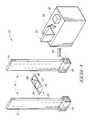
- FIG. 1is a perspective view of an article surveillance system embodying various aspects of the invention, including a tag shown partly broken away and showing an alarm in block diagram form.
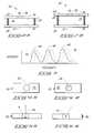
- FIG. 2Ais a simplified side view of the tag of FIG. 1, illustrating a magnetized state.
- FIG. 2Bis a simplified side view of the tag of FIG. 1, illustrating an unmagnetized state.
- FIG. 3is a plot of intensity versus frequency and illustrates a shift in frequency that occurs when the tag of FIG. 1 is in the magnetized state versus the unmagnetized state.
- FIG. 4Ais a simplified top view of a tag that provides an optical indication of change of state between amorphous and crystalline states, and illustrates the amorphous state.
- FIG. 4Bis a simplified top view of the tag of FIG. 4A, and illustrates the crystalline state.
- FIG. 5Ais a simplified side view of the tag of FIGS. 4A and 4B, illustrating the amorphous state.
- FIG. 5Bis a simplified side view of the tag of FIGS. 4A and 4B, illustrating the crystalline state.
- FIG. 1shows a security system 10 embodying various aspects of the invention.
- the systemincludes two antennas 12 and 14 which, in one embodiment, are arranged in respective housings to define a pedestal 16 of the type that can be placed so as to bracket a store entrance or placed proximate a checkout aisle.
- the systemincludes a transmitter 18 coupled to one of the antennas 12 and 14 and a receiver 20 coupled to the other of the antennas 12 and 14 .
- the antenna 12 coupled to the transmitter 18transmits pulses at a predetermined frequency.
- the system 10further includes a product label or tag 22 (FIGS. 2 A and 2 B).
- the tag 22includes a resonator 24 which is configured to vibrate at a frequency identical to the transmitted frequency when passed between the antennas 12 and 14 .
- the product labelincludes a magnetic strip 26 adjacent to the resonator 24 to keep the oscillations of the resonator 24 at the transmitted frequency.
- the tag 22includes (see FIGS. 2A and 2B) one or more pieces 28 of spongy or resilient material separating the strip 26 from the resonator 24 .
- the materialcould be, for example, foam, rubber, or other resilient material.
- the materialcould be only in the corners or dispersed more thoroughly between the resonator and the metal plate. Shallow bores or indents could be used to maintain the material in a desired location, such as in corners.
- the materialcould be defined by plastic or metal springs. Any appropriate material or location could be employed.
- At least portions of the insides (facing surfaces 30 and 32 ) of the strip 26 and resonator 24are made to be at least partially reflecting.
- One of the strip 26 and resonator 24has an opening or aperture 34 .
- the tag 22further includes a housing or covering 36 (see FIG. 1) which may be, for example, made of plastic or other suitable material.
- the housing 36may include a surface 37 which is intended to be affixed to or supported by products or inventory which is to be monitored.
- a double sided tape or an adhesive, such as a pressure sensitive adhesive,can be provided on this surface.
- the tag 22further includes a partially-silvered (e.g., half-silvered), or one-way mirror 38 or similar device configured to split incoming light such that a portion is reflected in one direction and another portion is transmitted in a second direction different from the first direction.
- the mirror 38is supported in or covers the opening or aperture 34 such that the partially-silvered surface faces the surface 32 (if the aperture 34 is in the strip 26 ) or the surface 30 (if the aperture 34 is in the resonator 24 ).
- a half-silvered mirroris one in which reflective molecules coat glass so sparsely that only about half the molecules needed to make the glass an opaque mirror are applied. Reflective molecules are speckled all over the glass in a generally even film, but only half of the glass is covered. The half-silvered surface will reflect about half the light that strikes its surface, while letting the other half go straight through.
- the overall size or size rangecan be the same as for existing tags.
- the tags 22are 1-2 cm long and a few mm wide.
- the magnetic force that controls the separation between the resonator 24 and magnetic strip 26is sufficient to overcome the effects of gravity such that the tag will operate correctly at any orientation, as is the case with present tags.
- the shift in frequency between the magnetized and unmagnetized statesresults in a difference in the color of light that exits the hole 34 . This difference gives an optical indication as to the state of magnetization.
- the receiver 20can be, for example, inside one of the pedestal arms or otherwise coupled to the antenna 14 .
- the receiver 20turns on at least between each transmitted pulse (e.g., during an interval between each transmitted pulse) so that it can pick up the signal emitted by the tag 22 if the resonator is vibrating at the correct predetermined frequency (e.g., the frequency used by the transmitter 18 ).
- the resonator 24will be vibrating at the correct frequency if the strip 26 is magnetized, but will not be vibrating at the correct frequency if the strip 26 is not magnetized.
- the system 10further includes (see FIG. 1) a deactivation device 50 that can turn off the tag when removal of an item is authorized (e.g., after receipt of a payment or accounting procedures have been complied with), by demagnetizing the strip 26 or altering its magnetic properties such that the resonator 24 either will not vibrate or will do so at a frequency different from the transmitted frequency.
- the deactivation device 50can be located, for example, proximate a point of sale terminal 52 .
- the system 10further includes an alarm 54 coupled to the receiver 20 . If the receiver 20 receives the signal from a tag 22 at the correct predetermined frequency, (e.g. once, four times, or some other predetermined number of times), an alarm is triggered. In one embodiment, instead of or in addition to an alarm being triggered, an exit is locked.
- the correct predetermined frequencye.g. once, four times, or some other predetermined number of times
- optical examination of the half silvered mirror 38shows the state of magnetization.
- FIGS. 4A, 4 B, 5 A, and 5 Bmakes use of a change between amorphous and crystalline states of a material to provide a an optical indication of state of magnetization.
- tagssuch as those described in incorporated U.S. Pat. No. 4,686,516 to Humphrey and U.S. Pat. No. 4,660,025 to Humphrey
- the molecular organization of an active component of a tagis changed to activate or deactivate the tag. More particularly, the tag is deactivated by selectively changing a component made of amorphous material to crystalline form, such as by adjusting temperature. Temperature is adjusted in part by applying radiant energy and adjusted in part by conducting electric current through the component.
- a similar property, based on a change of state responsive to current flow,is used in LCD displays.
- An optical indicatoris provided for tags of this or similar designs.
- FIGS. 4A and 4Bshow a top view of a tag 60 which make use of this principle.
- the tag 60is deactivated by selectively changing a component 62 made of amorphous material to crystalline form, such as by adjusting temperature. Temperature is selectively adjusted either by applying radiant energy, by conducting electric current through the component, or a combination.
- the tag 60includes a window 64 made of a polarizing material.
- the polarizing material in the windowcan be material of the type that is used in LCD displays, for example, or the type of material used in plastic sunglasses.
- the window 64is not necessarily made of a polarizing material, but is clear in one embodiment, but the material 62 is of a type that changes color or opacity between the amorphous and crystalline states.
- This materialcan be, for example, a phase-change chalcogenide alloy.
- a phase-change chalcogenide alloychanges from high resistance, nonreflective to low resistance reflective as its state changes from amorphous to crystalline.
- the inventorhas recognized that such a material would advantageously change from high resistance, nonreflective, to low resistance, reflective, as its state changes from amorphous to crystalline.
- Another material that could possibly be usedincludes, for example, N,N′-bis(2-phenylethyl)perylene-3,4:9,10-bis(dicarb oximide) which is discussed in an article by J. Mizuguchi, proceedings of Third Japan-France Joint Forum-Organic Materials for Electronics and Photonics, Apr. 6-8, 1998, Tsukuba, Japan, published in the journal Molecular Crystals and Liquid Crystals.
- Another material that could possibly be usedis an Nb/sub 2/O/sub 5/ or sol-gel niobium oxide which is discussed in an article by M. Schmitt, S. Heusing, M. A. Aegerter, A. Pawlicka, and C.
- Other materials that could possibly be usedinclude, for example, TbFe and GaTbFe; TbFeCo; TeSeSb; SeInSb; and alloys with various concentrations of Cu, Al, Ni and Zn such as discussed in an article titled Perspectives of reversible optical storage by F. Hoff, in the Czech journal Slaboproudy Obzor, vol. 48, no. 4, pp.197-8, published April 1987.
- Another material that could be usedis an amorphous-crystalline transformation of basic copper carbonates such as is discussed in an article titled Nucleation and crystal proliferation kinetics: amorphous-crystalline transformation of basic copper carbonates by A.C.T. Hsu, A.C.T. in the AlChE Journal, vol. 17, no. 6, pp.1311-15, published November 1971.
- Yet another material that could be usedis LaNiO3 such as is described in an article by H. Seim; H. Molsa; M. Nieminen; H. Fjellvag; and L. Niinisto in the JOURNAL OF MATERIALS CHEMISTRY, 1997, V7, N3 (MAR), P449-454.
- One applicationis in a warehouse. Items are scanned as they enter using a scanner that changes the magnetization of the tag 22 . If a scanned item is removed from the warehouse without authorization, an alarm or alarms are activated. If an item is not scanned as it enters the warehouse, the color of the tag 22 gives immediate feedback of the error. When an item is to be removed from the warehouse, a different scanner that reverses the magnetization is used. Again, the detectable change of the color via the aperture 34 provides feedback. After this second scan, the tag 22 will not activate alarms.
- Each medical supply item(or selected medical supply items), such as an IV bag, can carry one of the tags 22 which is additionally marked with machine readable markings, such as a bar code or UPC 56 .
- a scanner 56 that reads this bar codeis also configured to selectively demagnetize the tag 22 in a manner similar to that described, for example, in incorporated U.S. Pat. No. 5,979,758 to Swartz et al. This change in demagnetization is detectable as a change in color in the light exiting the aperture 34 .
- a simple detectable checkwill show if the item has been scanned by the scanner 56 . If the item is scanned in error, remagnetizing the tag 22 changes the color back.
- a scanner 56can be provided particularly for use in returning items to inventory, and this scanner 56 is also capable of remagnetizing the tag 22 .
- a pedestal 16 or antenna pair 12 , 14is provided at the exit of a garbage collection area. If an unscanned item is discarded, an alarm will sound before the trash is removed from the site.
- the tag 22is configured with a stiffer elastic material to make the color change undetectable to the human eye, but still detectable by the scanner 56 .
- the scanner 56can detect double scanning or the absence of an expected scan. It is also possible to provide special filters that make small color changes visible to the eye.
- an alternative separator piece 28is used that comprises air or one or more air filled bags.
- the baghas the metallic material on each side, and the window in one of the sides.
- the air pressurewould be such that the change in magnetic state would be enough to change the spacing of the metal plates.
- a foam materialcould be employed if air-tightness is a problem, but the foam would have to be very compressible and transparent at the wavelengths of interest.
- Another alternativeis to use rigid spacers at the end points. The change in magnetization will cause the metal plates to flex, changing the spacing at the location of the window.
Landscapes
- Physics & Mathematics (AREA)
- Engineering & Computer Science (AREA)
- Automation & Control Theory (AREA)
- Computer Security & Cryptography (AREA)
- Electromagnetism (AREA)
- General Physics & Mathematics (AREA)
- Burglar Alarm Systems (AREA)
Abstract
Description
Claims (29)
Priority Applications (1)
| Application Number | Priority Date | Filing Date | Title |
|---|---|---|---|
| US10/184,970US6752837B2 (en) | 2002-06-28 | 2002-06-28 | Security tags with a reversible optical indicator |
Applications Claiming Priority (1)
| Application Number | Priority Date | Filing Date | Title |
|---|---|---|---|
| US10/184,970US6752837B2 (en) | 2002-06-28 | 2002-06-28 | Security tags with a reversible optical indicator |
Publications (2)
| Publication Number | Publication Date |
|---|---|
| US20040000998A1 US20040000998A1 (en) | 2004-01-01 |
| US6752837B2true US6752837B2 (en) | 2004-06-22 |
Family
ID=29779486
Family Applications (1)
| Application Number | Title | Priority Date | Filing Date |
|---|---|---|---|
| US10/184,970Expired - LifetimeUS6752837B2 (en) | 2002-06-28 | 2002-06-28 | Security tags with a reversible optical indicator |
Country Status (1)
| Country | Link |
|---|---|
| US (1) | US6752837B2 (en) |
Cited By (24)
| Publication number | Priority date | Publication date | Assignee | Title |
|---|---|---|---|---|
| US20030210144A1 (en)* | 2002-03-08 | 2003-11-13 | Reinhold Ott | Sensor element for a monitoring device |
| US20050279000A1 (en)* | 2004-06-18 | 2005-12-22 | Molinaro Joseph J | Store security device with advertising cover |
| US20050284358A1 (en)* | 2004-06-23 | 2005-12-29 | Infineon Technologies Ag | Radio-interrogable data storage medium |
| US20060017574A1 (en)* | 2002-07-29 | 2006-01-26 | Johan Skjellerup | Security tag assembly |
| US20060125643A1 (en)* | 2004-12-09 | 2006-06-15 | Johan Skjellerup | Security system for preventing unauthorized removal of merchandise |
| US20060208908A1 (en)* | 2004-12-09 | 2006-09-21 | Johan Skjellerup | Security system for preventing unauthorized removal of merchandise |
| US20070052521A1 (en)* | 2005-09-02 | 2007-03-08 | Micro Trak Gps, Inc. | Mounting apparatus for radio frequency identification system |
| US20070273523A1 (en)* | 2004-12-09 | 2007-11-29 | Johan Skjellerup | Security system for preventing unauthorized removal of merchandise |
| US20080291029A1 (en)* | 2004-12-09 | 2008-11-27 | Johan Skjellerup | Security system for preventing unauthorized removal of merchandise |
| US20090128341A1 (en)* | 2004-12-09 | 2009-05-21 | Johan Skjellerup | Security system for preventing unauthorized removal of merchandise |
| USD603739S1 (en) | 2002-07-29 | 2009-11-10 | Johan Skjellerup | Security tag design |
| US20090295583A1 (en)* | 2004-09-09 | 2009-12-03 | Forster Ian J | Rfid tags with eas deactivation ability |
| US20110050427A1 (en)* | 2004-12-09 | 2011-03-03 | Johan Skjellerup | Security tag assembly |
| US20110205030A1 (en)* | 2010-02-03 | 2011-08-25 | Nxp B.V. | Method of de-activating and activating an electronic article surveillance (esa) device, and an eas device |
| US20120044074A1 (en)* | 2010-08-20 | 2012-02-23 | Symbol Technologies, Inc. | Electronic article surveillance systems, apparatus, and methods |
| US20120154151A1 (en)* | 2010-09-27 | 2012-06-21 | Genevieve Kuhn | Desiccant canister and eas rf tag |
| US8210439B2 (en) | 2010-08-02 | 2012-07-03 | International Business Machines Corporation | Merchandise security tag for an article of merchandise |
| US8590349B2 (en) | 2012-03-20 | 2013-11-26 | Braebum Asset Holdings, LLC. | Security tag assembly |
| US8590348B1 (en) | 2011-10-31 | 2013-11-26 | Braebum Asset Holdings, LLC. | Security tag assembly |
| USD709888S1 (en)* | 2012-07-02 | 2014-07-29 | Symbol Technologies, Inc. | Bi-optic imaging scanner module |
| USD730901S1 (en)* | 2014-06-24 | 2015-06-02 | Hand Held Products, Inc. | In-counter barcode scanner |
| EP3059697A1 (en) | 2015-02-19 | 2016-08-24 | Margento R&D D.o.o. | Smart optical tag |
| US10096217B2 (en) | 2016-05-11 | 2018-10-09 | Braeburn Asset Holdings, Llc | Security system and security tag assembly |
| US10451588B2 (en)* | 2014-08-27 | 2019-10-22 | 3M Innovative Properties Company | Magneto-mechanical resonator sensor with mass distribution channel |
Families Citing this family (10)
| Publication number | Priority date | Publication date | Assignee | Title |
|---|---|---|---|---|
| US20060149621A1 (en)* | 2004-12-30 | 2006-07-06 | Do Phuc K | Method to provide tactile or audio feedback in a personal shopping device |
| US7337962B2 (en)* | 2004-12-30 | 2008-03-04 | International Business Machines Corporation | Method to detect false purchases with a consumer service device |
| US8588506B2 (en) | 2011-04-27 | 2013-11-19 | Eastman Kodak Company | Image algorithms to reject undesired image features |
| US8681004B2 (en)* | 2011-04-27 | 2014-03-25 | Eastman Kodak Company | Deactivation of a security feature |
| US8750621B2 (en) | 2011-04-27 | 2014-06-10 | Eastman Kodak Company | Method of authenticating security marker |
| US9526228B2 (en)* | 2014-03-07 | 2016-12-27 | Amirix Systems Inc. | Predation detection fish tracking tag |
| CA2903243C (en) | 2014-11-19 | 2021-06-01 | Amirix Systems Inc. | Predation detection animal tracking tag |
| US10580273B2 (en)* | 2017-12-08 | 2020-03-03 | Sensormatic Electronics, LLC | Shielded pedestal with see-thru capability |
| MX2021011834A (en) | 2019-03-29 | 2022-02-22 | Saint Gobain Abrasives Inc | PERFORMANCE GRINDING SOLUTIONS. |
| CA3135979C (en) | 2019-04-03 | 2023-12-19 | Saint-Gobain Abrasives, Inc. | Abrasive article, abrasive system and method for using and forming same |
Citations (28)
| Publication number | Priority date | Publication date | Assignee | Title |
|---|---|---|---|---|
| US3895368A (en) | 1972-08-09 | 1975-07-15 | Sensormatic Electronics Corp | Surveillance system and method utilizing both electrostatic and electromagnetic fields |
| US3995900A (en) | 1973-12-27 | 1976-12-07 | Sensormatic Electronics Corporation | Reusable security tag |
| US4063229A (en) | 1967-03-30 | 1977-12-13 | Sensormatic Electronics Corporation | Article surveillance |
| US4510489A (en) | 1982-04-29 | 1985-04-09 | Allied Corporation | Surveillance system having magnetomechanical marker |
| US4622543A (en)* | 1984-03-22 | 1986-11-11 | Anderson Iii Philip M | Surveillance system having acoustic magnetomechanical marker |
| US4660025A (en) | 1984-11-26 | 1987-04-21 | Sensormatic Electronics Corporation | Article surveillance magnetic marker having an hysteresis loop with large Barkhausen discontinuities |
| US4686516A (en) | 1984-11-26 | 1987-08-11 | Sensormatic Electronics Corporation | Method, system and apparatus for use in article surveillance |
| US4967185A (en)* | 1989-08-08 | 1990-10-30 | Minnesota Mining And Manufacturing Company | Multi-directionally responsive, dual-status, magnetic article surveillance marker having continuous keeper |
| US5006856A (en) | 1989-08-23 | 1991-04-09 | Monarch Marking Systems, Inc. | Electronic article surveillance tag and method of deactivating tags |
| US5313192A (en) | 1992-07-02 | 1994-05-17 | Sensormatic Electronics Corp. | Deactivatable/reactivatable magnetic marker having a step change in magnetic flux |
| US5351033A (en)* | 1992-10-01 | 1994-09-27 | Sensormatic Electronics Corporation | Semi-hard magnetic elements and method of making same |
| US5495230A (en) | 1994-06-30 | 1996-02-27 | Sensormatic Electronics Corporation | Magnetomechanical article surveillance marker with a tunable resonant frequency |
| US5729200A (en) | 1996-08-28 | 1998-03-17 | Sensormatic Electronics Corporation | Magnetomechanical electronic article surveilliance marker with bias element having abrupt deactivation/magnetization characteristic |
| US5942978A (en) | 1998-04-24 | 1999-08-24 | Sensormatic Electronics Corporation | Wireless transmitter key for EAS tag detacher unit |
| US5949318A (en) | 1994-08-10 | 1999-09-07 | Sensormatic Electronics Corporation | Apparatus for activating/deactivating sensors used with EAS tags |
| US5955951A (en) | 1998-04-24 | 1999-09-21 | Sensormatic Electronics Corporation | Combined article surveillance and product identification system |
| US5963173A (en) | 1997-12-05 | 1999-10-05 | Sensormatic Electronics Corporation | Antenna and transmitter arrangement for EAS system |
| US5979758A (en) | 1988-08-25 | 1999-11-09 | Symbol Technologies, Inc. | Self-checkout point-of-transaction system including deactivatable electro-optically coded surveillance tags |
| US5990794A (en) | 1996-09-26 | 1999-11-23 | Sensormatic Electronics Corporation | Apparatus for data communication and deactivation of electronic article surveillance tags |
| US6011474A (en) | 1998-04-28 | 2000-01-04 | Sensormatic Electronics Corporation | Multiple-use deactivation device for electronic article surveillance markers |
| US6061552A (en) | 1998-04-28 | 2000-05-09 | Sensormatic Electronics Corporation | EAS pedestal and method for making the same |
| US6281796B1 (en) | 1999-10-29 | 2001-08-28 | Sensormatic Electronics Corporation | Point-of sale reader and electronic article surveillance tag deactivator interface |
| US6307474B1 (en) | 2000-08-22 | 2001-10-23 | Sensormatic Electronics Corporation | Magnetomechanical electronic article surveillance system and method using sideband detection |
| US6320507B1 (en) | 2000-04-07 | 2001-11-20 | Sensormatic Electronics Corporation | Method for synchronization between systems |
| US6339378B2 (en) | 1999-06-08 | 2002-01-15 | Unisensor Corporation | Anti-theft tack device |
| US6351216B1 (en) | 2001-02-05 | 2002-02-26 | Sensormatic Electronics Corporation | Large signal noise cancellation in electronic article surveillance |
| US6352606B1 (en) | 1999-07-15 | 2002-03-05 | Timex Group B.V. | Consumer article security arrangement |
| US6359563B1 (en)* | 1999-02-10 | 2002-03-19 | Vacuumschmelze Gmbh | ‘Magneto-acoustic marker for electronic article surveillance having reduced size and high signal amplitude’ |
- 2002
- 2002-06-28USUS10/184,970patent/US6752837B2/ennot_activeExpired - Lifetime
Patent Citations (28)
| Publication number | Priority date | Publication date | Assignee | Title |
|---|---|---|---|---|
| US4063229A (en) | 1967-03-30 | 1977-12-13 | Sensormatic Electronics Corporation | Article surveillance |
| US3895368A (en) | 1972-08-09 | 1975-07-15 | Sensormatic Electronics Corp | Surveillance system and method utilizing both electrostatic and electromagnetic fields |
| US3995900A (en) | 1973-12-27 | 1976-12-07 | Sensormatic Electronics Corporation | Reusable security tag |
| US4510489A (en) | 1982-04-29 | 1985-04-09 | Allied Corporation | Surveillance system having magnetomechanical marker |
| US4622543A (en)* | 1984-03-22 | 1986-11-11 | Anderson Iii Philip M | Surveillance system having acoustic magnetomechanical marker |
| US4686516A (en) | 1984-11-26 | 1987-08-11 | Sensormatic Electronics Corporation | Method, system and apparatus for use in article surveillance |
| US4660025A (en) | 1984-11-26 | 1987-04-21 | Sensormatic Electronics Corporation | Article surveillance magnetic marker having an hysteresis loop with large Barkhausen discontinuities |
| US5979758A (en) | 1988-08-25 | 1999-11-09 | Symbol Technologies, Inc. | Self-checkout point-of-transaction system including deactivatable electro-optically coded surveillance tags |
| US4967185A (en)* | 1989-08-08 | 1990-10-30 | Minnesota Mining And Manufacturing Company | Multi-directionally responsive, dual-status, magnetic article surveillance marker having continuous keeper |
| US5006856A (en) | 1989-08-23 | 1991-04-09 | Monarch Marking Systems, Inc. | Electronic article surveillance tag and method of deactivating tags |
| US5313192A (en) | 1992-07-02 | 1994-05-17 | Sensormatic Electronics Corp. | Deactivatable/reactivatable magnetic marker having a step change in magnetic flux |
| US5351033A (en)* | 1992-10-01 | 1994-09-27 | Sensormatic Electronics Corporation | Semi-hard magnetic elements and method of making same |
| US5495230A (en) | 1994-06-30 | 1996-02-27 | Sensormatic Electronics Corporation | Magnetomechanical article surveillance marker with a tunable resonant frequency |
| US5949318A (en) | 1994-08-10 | 1999-09-07 | Sensormatic Electronics Corporation | Apparatus for activating/deactivating sensors used with EAS tags |
| US5729200A (en) | 1996-08-28 | 1998-03-17 | Sensormatic Electronics Corporation | Magnetomechanical electronic article surveilliance marker with bias element having abrupt deactivation/magnetization characteristic |
| US5990794A (en) | 1996-09-26 | 1999-11-23 | Sensormatic Electronics Corporation | Apparatus for data communication and deactivation of electronic article surveillance tags |
| US5963173A (en) | 1997-12-05 | 1999-10-05 | Sensormatic Electronics Corporation | Antenna and transmitter arrangement for EAS system |
| US5942978A (en) | 1998-04-24 | 1999-08-24 | Sensormatic Electronics Corporation | Wireless transmitter key for EAS tag detacher unit |
| US5955951A (en) | 1998-04-24 | 1999-09-21 | Sensormatic Electronics Corporation | Combined article surveillance and product identification system |
| US6061552A (en) | 1998-04-28 | 2000-05-09 | Sensormatic Electronics Corporation | EAS pedestal and method for making the same |
| US6011474A (en) | 1998-04-28 | 2000-01-04 | Sensormatic Electronics Corporation | Multiple-use deactivation device for electronic article surveillance markers |
| US6359563B1 (en)* | 1999-02-10 | 2002-03-19 | Vacuumschmelze Gmbh | ‘Magneto-acoustic marker for electronic article surveillance having reduced size and high signal amplitude’ |
| US6339378B2 (en) | 1999-06-08 | 2002-01-15 | Unisensor Corporation | Anti-theft tack device |
| US6352606B1 (en) | 1999-07-15 | 2002-03-05 | Timex Group B.V. | Consumer article security arrangement |
| US6281796B1 (en) | 1999-10-29 | 2001-08-28 | Sensormatic Electronics Corporation | Point-of sale reader and electronic article surveillance tag deactivator interface |
| US6320507B1 (en) | 2000-04-07 | 2001-11-20 | Sensormatic Electronics Corporation | Method for synchronization between systems |
| US6307474B1 (en) | 2000-08-22 | 2001-10-23 | Sensormatic Electronics Corporation | Magnetomechanical electronic article surveillance system and method using sideband detection |
| US6351216B1 (en) | 2001-02-05 | 2002-02-26 | Sensormatic Electronics Corporation | Large signal noise cancellation in electronic article surveillance |
Non-Patent Citations (8)
| Title |
|---|
| Hoff, F., "Perspectives of Reversible Optical Storage", Slaboproudy Obzor (Journal from Czechoslovakia), vol. 48, No. 4, p. 197-8 (Apr. 1987). |
| Hsu, A.C.T., "Nucleation and Crystal proliferation Kinetics: *Amorphous*", AIChE Journal, vol. 17, No. 6, p. 1311-15 (Nov. 1971). |
| Mizuguchi, J., et al., "Phase Change of N,N'-bis (2-phenylethyl) perylene-3, 4:9, 10-bis (dicarboximide) for Information Storage Applications", Molecular Crystals and Liquid Crystals Conference (Switzerland), vol. 322, p. 291-8 (1998). |
| Mizuguchi, J., et al., "Phase Change of N,N′-bis (2-phenylethyl) perylene-3, 4:9, 10-bis (dicarboximide) for Information Storage Applications", Molecular Crystals and Liquid Crystals Conference (Switzerland), vol. 322, p. 291-8 (1998). |
| Ovonyx, Inc., web site, short technical presentation in HTML, entitled "Ovonic Unifieid Memory", http://www.ovonyx.com/tech13html.html, 3 pages (Printed Jun. 18, 2002). |
| Ryan, Jr., Joseph, "Working Knowledge", Scientific American, p. 120 (May 1997). |
| Schmitt, M., et al., "Electrochromic properties of Nb/sub 2/0sub 5/sol-gel Coatings", Solar Energy Materials and Solar Cells, vol. 54, No. 1-4, p. 9-17 (Aug. 1998). |
| Seim H., et al., "Deposition of LaNi03 Thin Films in an Atomic Layer Epitaxy Reactor", Journal of Materials Chemistry, vol. 7, No. 3, p. 449-454 (Mar. 1997). |
Cited By (41)
| Publication number | Priority date | Publication date | Assignee | Title |
|---|---|---|---|---|
| US7079031B2 (en)* | 2002-03-08 | 2006-07-18 | Reinhold Ott | Sensor element for a monitoring device |
| US20030210144A1 (en)* | 2002-03-08 | 2003-11-13 | Reinhold Ott | Sensor element for a monitoring device |
| US20060208921A1 (en)* | 2002-03-08 | 2006-09-21 | Reinhold Ott | Sensor element for a monitoring device |
| US20060017574A1 (en)* | 2002-07-29 | 2006-01-26 | Johan Skjellerup | Security tag assembly |
| USD603739S1 (en) | 2002-07-29 | 2009-11-10 | Johan Skjellerup | Security tag design |
| US7523630B2 (en) | 2002-07-29 | 2009-04-28 | Johan Skjellerup | Security tag assembly |
| WO2006002164A3 (en)* | 2004-06-18 | 2006-12-07 | Joseph J Molinaro | Store scurity device with advertising cover |
| US20050279000A1 (en)* | 2004-06-18 | 2005-12-22 | Molinaro Joseph J | Store security device with advertising cover |
| US7299578B2 (en)* | 2004-06-18 | 2007-11-27 | Joseph J Molinaro | Store security device with advertising cover |
| US7481178B2 (en)* | 2004-06-23 | 2009-01-27 | Infineon Technologies Ag | Radio-interrogable data storage medium |
| US20050284358A1 (en)* | 2004-06-23 | 2005-12-29 | Infineon Technologies Ag | Radio-interrogable data storage medium |
| US8072332B2 (en)* | 2004-09-09 | 2011-12-06 | Avery Dennison Corporation | RFID tags with EAS deactivation ability |
| US20090295583A1 (en)* | 2004-09-09 | 2009-12-03 | Forster Ian J | Rfid tags with eas deactivation ability |
| US7286054B2 (en) | 2004-12-09 | 2007-10-23 | Johan Skjellerup | Security system for preventing unauthorized removal of merchandise |
| US20110050427A1 (en)* | 2004-12-09 | 2011-03-03 | Johan Skjellerup | Security tag assembly |
| US7474216B2 (en) | 2004-12-09 | 2009-01-06 | Johan Skjellerup | Security system for preventing unauthorized removal of merchandise |
| US7382256B2 (en)* | 2004-12-09 | 2008-06-03 | Johan Skjellerup | Security system for preventing unauthorized removal of merchandise |
| US20070273523A1 (en)* | 2004-12-09 | 2007-11-29 | Johan Skjellerup | Security system for preventing unauthorized removal of merchandise |
| US20090128341A1 (en)* | 2004-12-09 | 2009-05-21 | Johan Skjellerup | Security system for preventing unauthorized removal of merchandise |
| US8242910B2 (en) | 2004-12-09 | 2012-08-14 | Johan Skjellerup | Security system for preventing unauthorized removal of merchandise |
| US20060208908A1 (en)* | 2004-12-09 | 2006-09-21 | Johan Skjellerup | Security system for preventing unauthorized removal of merchandise |
| US7817041B2 (en) | 2004-12-09 | 2010-10-19 | Johan Skjellerup | Security system for preventing unauthorized removal of merchandise |
| US8223022B2 (en) | 2004-12-09 | 2012-07-17 | Johan Skjellerup | Security tag assembly |
| US20080291029A1 (en)* | 2004-12-09 | 2008-11-27 | Johan Skjellerup | Security system for preventing unauthorized removal of merchandise |
| US20060125643A1 (en)* | 2004-12-09 | 2006-06-15 | Johan Skjellerup | Security system for preventing unauthorized removal of merchandise |
| US20070052521A1 (en)* | 2005-09-02 | 2007-03-08 | Micro Trak Gps, Inc. | Mounting apparatus for radio frequency identification system |
| US20110205030A1 (en)* | 2010-02-03 | 2011-08-25 | Nxp B.V. | Method of de-activating and activating an electronic article surveillance (esa) device, and an eas device |
| US8749357B2 (en)* | 2010-02-03 | 2014-06-10 | Nxp B.V. | Method of de-activating and activating an electronic article surveillance (EAS) device, and an EAS device |
| US8210439B2 (en) | 2010-08-02 | 2012-07-03 | International Business Machines Corporation | Merchandise security tag for an article of merchandise |
| US20120044074A1 (en)* | 2010-08-20 | 2012-02-23 | Symbol Technologies, Inc. | Electronic article surveillance systems, apparatus, and methods |
| US8587432B2 (en)* | 2010-08-20 | 2013-11-19 | Symbol Technologies, Inc. | Electronic article surveillance systems, apparatus, and methods |
| US20120154151A1 (en)* | 2010-09-27 | 2012-06-21 | Genevieve Kuhn | Desiccant canister and eas rf tag |
| US8590348B1 (en) | 2011-10-31 | 2013-11-26 | Braebum Asset Holdings, LLC. | Security tag assembly |
| US8590349B2 (en) | 2012-03-20 | 2013-11-26 | Braebum Asset Holdings, LLC. | Security tag assembly |
| USD709888S1 (en)* | 2012-07-02 | 2014-07-29 | Symbol Technologies, Inc. | Bi-optic imaging scanner module |
| USD730901S1 (en)* | 2014-06-24 | 2015-06-02 | Hand Held Products, Inc. | In-counter barcode scanner |
| USD757009S1 (en) | 2014-06-24 | 2016-05-24 | Hand Held Products, Inc. | In-counter barcode scanner |
| US10451588B2 (en)* | 2014-08-27 | 2019-10-22 | 3M Innovative Properties Company | Magneto-mechanical resonator sensor with mass distribution channel |
| EP3059697A1 (en) | 2015-02-19 | 2016-08-24 | Margento R&D D.o.o. | Smart optical tag |
| US10096217B2 (en) | 2016-05-11 | 2018-10-09 | Braeburn Asset Holdings, Llc | Security system and security tag assembly |
| US10332372B2 (en) | 2016-05-11 | 2019-06-25 | Braeburn Asset Holdings, Llc | Security system and security tag assembly |
Also Published As
| Publication number | Publication date |
|---|---|
| US20040000998A1 (en) | 2004-01-01 |
Similar Documents
| Publication | Publication Date | Title |
|---|---|---|
| US6752837B2 (en) | Security tags with a reversible optical indicator | |
| EP0928472B1 (en) | An apparatus for data communication and deactivation of electronic article surveillance tags | |
| US8976030B2 (en) | Point of sale (POS) based checkout system supporting a customer-transparent two-factor authentication process during product checkout operations | |
| EP2482261B1 (en) | Bar code symbol reading system employing EAS-enabling faceplate bezel | |
| US6154135A (en) | Apparatus for capturing data and deactivating electronic article surveillance tags | |
| US8011579B2 (en) | Combined data reader and electronic article surveillance (EAS) system | |
| AU2001253145B2 (en) | Electronic article surveillance and identification device, system, and method | |
| EP1481378B1 (en) | Systems and methods for data reading and eas tag sensing and deactivating at retail checkout | |
| CA2266395C (en) | A data communication and electronic article surveillance tag | |
| US4510489A (en) | Surveillance system having magnetomechanical marker | |
| EP0096182B1 (en) | Coded surveillance system having magnetomechanical marker | |
| EP0986798B1 (en) | Deactivation device with biplanar deactivation | |
| AU755677B2 (en) | Multiple-use deactivation device for electronic article surveillance markers | |
| US5973606A (en) | Activation/deactivation system and method for electronic article surveillance markers for use on a conveyor | |
| CA2447128C (en) | Apparatus for electronic article surveillance tag pollution reduction | |
| WO2001084519A2 (en) | Hand-held scanner deactivator to deactivate magnetomechanical eas markers | |
| WO1998024075A1 (en) | Universal merchandise tag | |
| HK1023436B (en) | An apparatus for data communication and deactivation of electronic article surveillance tags | |
| HK1129049A1 (en) | Electronic article surveillance activator/deactivator and method therefor | |
| HK1129049B (en) | Electronic article surveillance activator/deactivator and method therefor |
Legal Events
| Date | Code | Title | Description |
|---|---|---|---|
| AS | Assignment | Owner name:HEWLETT-PACKARD COMPANY, COLORADO Free format text:ASSIGNMENT OF ASSIGNORS INTEREST;ASSIGNOR:KARP, ALAN H.;REEL/FRAME:013073/0208 Effective date:20020621 | |
| AS | Assignment | Owner name:HEWLETT-PACKARD COMPANY, COLORADO Free format text:ASSIGNMENT OF ASSIGNORS INTEREST;ASSIGNOR:KARP, ALAN H.;REEL/FRAME:013494/0222 Effective date:20020621 | |
| AS | Assignment | Owner name:HEWLETT-PACKARD DEVELOPMENT COMPANY, L.P., COLORADO Free format text:ASSIGNMENT OF ASSIGNORS INTEREST;ASSIGNOR:HEWLETT-PACKARD COMPANY;REEL/FRAME:013776/0928 Effective date:20030131 Owner name:HEWLETT-PACKARD DEVELOPMENT COMPANY, L.P., COLORAD Free format text:ASSIGNMENT OF ASSIGNORS INTEREST;ASSIGNOR:HEWLETT-PACKARD COMPANY;REEL/FRAME:013776/0928 Effective date:20030131 Owner name:HEWLETT-PACKARD DEVELOPMENT COMPANY, L.P.,COLORADO Free format text:ASSIGNMENT OF ASSIGNORS INTEREST;ASSIGNOR:HEWLETT-PACKARD COMPANY;REEL/FRAME:013776/0928 Effective date:20030131 | |
| AS | Assignment | Owner name:HEWLETT-PACKARD DEVELOPMENT COMPANY L.P., TEXAS Free format text:ASSIGNMENT OF ASSIGNORS INTEREST;ASSIGNOR:HEWLETT-PACKARD COMPANY;REEL/FRAME:014061/0492 Effective date:20030926 Owner name:HEWLETT-PACKARD DEVELOPMENT COMPANY L.P.,TEXAS Free format text:ASSIGNMENT OF ASSIGNORS INTEREST;ASSIGNOR:HEWLETT-PACKARD COMPANY;REEL/FRAME:014061/0492 Effective date:20030926 | |
| STCF | Information on status: patent grant | Free format text:PATENTED CASE | |
| FPAY | Fee payment | Year of fee payment:4 | |
| REMI | Maintenance fee reminder mailed | ||
| FPAY | Fee payment | Year of fee payment:8 | |
| AS | Assignment | Owner name:ROUND ROCK RESEARCH, LLC, NEW JERSEY Free format text:ASSIGNMENT OF ASSIGNORS INTEREST;ASSIGNORS:HEWLETT-PACKARD DEVELOPMENT COMPANY, L.P.;HEWLETT-PACKARD COMPANY;REEL/FRAME:036134/0534 Effective date:20150715 | |
| FPAY | Fee payment | Year of fee payment:12 |