US6752807B2 - Transverse rod connector clip - Google Patents
Transverse rod connector clipDownload PDFInfo
- Publication number
- US6752807B2 US6752807B2US10/308,680US30868002AUS6752807B2US 6752807 B2US6752807 B2US 6752807B2US 30868002 AUS30868002 AUS 30868002AUS 6752807 B2US6752807 B2US 6752807B2
- Authority
- US
- United States
- Prior art keywords
- clip body
- rod
- elongated
- pair
- transverse connector
- Prior art date
- Legal status (The legal status is an assumption and is not a legal conclusion. Google has not performed a legal analysis and makes no representation as to the accuracy of the status listed.)
- Expired - Fee Related
Links
Images


Classifications
- A—HUMAN NECESSITIES
- A61—MEDICAL OR VETERINARY SCIENCE; HYGIENE
- A61B—DIAGNOSIS; SURGERY; IDENTIFICATION
- A61B17/00—Surgical instruments, devices or methods
- A61B17/56—Surgical instruments or methods for treatment of bones or joints; Devices specially adapted therefor
- A61B17/58—Surgical instruments or methods for treatment of bones or joints; Devices specially adapted therefor for osteosynthesis, e.g. bone plates, screws or setting implements
- A61B17/68—Internal fixation devices, including fasteners and spinal fixators, even if a part thereof projects from the skin
- A61B17/70—Spinal positioners or stabilisers, e.g. stabilisers comprising fluid filler in an implant
- A61B17/7049—Connectors, not bearing on the vertebrae, for linking longitudinal elements together
- A61B17/7052—Connectors, not bearing on the vertebrae, for linking longitudinal elements together of variable angle or length
Definitions
- the present inventionrelates to implantable spinal fixation systems for the surgical treatment of spinal disorders. More particularly, this invention relates to a transverse rod connector clip for connecting cylindrical rods to each other.
- spinal implant systemshave been developed to add stability to the spine to enhance the arthrodesis rates.
- Such systemsoften include spinal instrumentation having connective structures such as a pair of plates and/or rods which are placed on opposite sides of the portion of the spinal column which is intended to be fused.
- spinal systemsconsist of screws and hooks for segmental attachment to the spine and longitudinal rods connected to screws or hooks.
- a cross brace assemblyis disclosed in U.S. Pat. No, 5,084,049. Devices such as these commonly consist of a threaded rod for providing the desired lateral support. The threaded rod is fastened to each of the spinal rods by clamps located on each end of the threaded rod.
- this configurationis bulky and can cause irritation of the patient's back muscles and other tissue which might rub against the device.
- a cross brace assemblythat fits closer to the spine, preferably in the same general plane as the vertical spinal rods, would reduce the complications associated with bulkier devices.
- transverse connectorsconsist of rods, plates, and bars linked to the longitudinal rods by coupling mechanisms with set screws, nuts, or a combination of each. These connectors require several components and instruments to build the constructs. Each additional component or instrument required to assemble the connectors adds to the “fiddle factor” of the surgical technique. Examples of these transverse connectors include Tranverse Link Device (DLT) and Crosslink manufactured by Sofamor Danek, Trans-Connector manufactured by Synthes, and Modular Cross Connector and Transverse Rod Connector (TRC) manufactured by AcroMed.
- DLTTranverse Link Device
- Crosslinkmanufactured by Sofamor Danek
- TRCModular Cross Connector and Transverse Rod Connector manufactured by AcroMed.
- Telescopic rod to rod couplers for use in a spinal implant systemshave also been described. Prior to the locking member being engaged, the telescoping sections may be easily slid past their extremes and out of engagement with one another. While this is a convenient method of connecting and disconnecting the coupler sections, it can be inconvenient during surgery if the sections accidentally disengage.
- U.S. Pat. No. 5,275,600describes a telescopic rod to rod coupler in which the telescopic rod sections are assembled together using a 180 degree twisting motion. This is designed to minimize the risk of the rod sections accidentally disconnecting during the implant procedure.
- a spinal fixation systemincludes: a first clip body having a pair of opposed spaced apart arcuate rod engaging hooks depending from a first side thereof for engaging a first elongated spinal rod, and a transverse connector extending laterally from a second side thereof; a second clip body having a pair of opposed spaced apart arcuate rod engaging hooks depending from a first side thereof for engaging a second elongated spinal rod, and a transverse connector extending laterally from a second side thereof; and a fastener for securing the transverse connector of the first elongated clip body and the transverse connector of the second elongated clip body to one another.
- a spinal fixation systemincludes: a first clip body having a first pair of opposed spaced apart arcuate engaging hooks depending from a first side thereof for engaging a first elongated spinal rod, and a second pair of opposed spaced apart arcuate engaging hooks depending from a second side thereof for engaging an elongated transverse connector; and a second clip body having a first pair of opposed spaced apart arcuate engaging hooks depending from a first side thereof for engaging a second elongated spinal rod, and a second pair of opposed spaced apart arcuate engaging hooks depending from a second side thereof for engaging the elongated transverse connector.
- a spinal fixation systemincludes: an elongated spinal rod; a transverse member; and a connector having a pair of opposed spaced apart arcuate rod engaging hooks for receiving and engaging the elongated spinal rod, the connector securing the elongated spinal rod and the transverse member in a transverse orientation in which the elongated spinal rod are substantially coplanar.
- the transverse connector clips of the present inventioncan be used to transversely connect spinal rods without requiring additional manipulation of the spinal instrumentation. Because the clips of the present invention do not require any additional locking mechanism, they reduce the assembly of small pieces of hardware during the surgical procedure.
- FIG. 1is a top perspective view of one embodiment of a transverse connector clip of the present invention
- FIG. 2is a perspective view of one embodiment of the transverse connector clip of the present invention with a short, laterally extending bar;
- FIG. 3is a top perspective view of another embodiment of a transverse connector clip of the present invention with a laterally extending bar having a plurality of vertical teeth;
- FIG. 4is a bottom perspective view of the invention clip of FIG. 3;
- FIG. 5is a perspective view of a pair of the connecting transverse connector clips of FIG. 3;
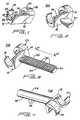
- FIG. 6is a perspective view of the clip of FIG. 2 securing the transverse connector clips of FIG. 5;
- FIG. 7is a schematic view of the present invention connected to spinal rods implanted in a human spine and illustrating the method of assembly;
- FIG. 8is a top perspective view an another embodiment of the present invention.
- FIG. 9is a bottom perspective view of the invention of FIG. 8;
- FIG. 10is perspective view of the invention of FIG. 8 illustrating the connecting mechanism of the connector clip
- FIG. 11is a perspective view of the invention of FIG. 8 connected to the ends of an T-bar;
- FIG. 12is a perspective view of an another embodiment of the present invention illustrating the method of assembly of two connector clips having laterally extending tapered bars connected together with a tapered sleeve;
- FIG. 13is a perspective view of the invention of FIG. 12 illustrating a range of lateral adjustment between the two clips;
- FIG. 14is a schematic view of the invention of FIG. 13 connected to spinal rods implanted in a human spine and illustrating the method of assembly;
- FIG. 15is a perspective view of another embodiment of the present invention illustrating the method of assembly.
- FIG. 16is a perspective view of the assembled invention of FIG. 15 .
- the present inventionis directed to a transverse connector clip 10 and assemblies used in spinal fixation systems.
- Spinal fixation systemstypically include spinal instrumentation having connective structures such as a pair of plates and/or rods which are placed on opposite sides of the spinal column near vertebrae that are intended to be fused.
- These spinal systemsconsist of screws and hooks for segmental attachment to the spine and longitudinal rods connected to screws or hooks. These components provide the necessary stability both in tension and compression yet yield minimal torsional control.
- transverse connector clips 10 of the present inventionconsist of a component with a means to clip the device on a spinal or cylindrical rod 11 and a component with a means to link two rod connectors together laterally.
- Transverse connector clip 10 conceptconsists of a clip body 12 with a first side 14 and a second side 16 (FIG. 1 ).
- first side 14On first side 14 are two, mirror image hemi-cylindrical shells 18 and 20 .
- These two, mirror image hemi-cylindrical shells 18 and 20have an inner surface 24 that defines a rod bore 26 through which the cylindrical rod 11 can extend.
- Rod bore 26has an inner diameter 22 that is designed to be slightly smaller than the outer diameter of the cylindrical rod 11 it will receive.
- Top surface 28 of the hemi-cylindrical shells 18 and 20defines an outer diameter 30 .
- the two, mirror image hemi-cylindrical shells 18 and 20can be connected to the first side 14 of clip body 12 as shown in clip 10 A of FIG. 2 or in mirror image relationship as shown in clip 10 A of FIG. 6 .
- Clip body 12is placed on the cylindrical rod 11 at 90 degrees and turned so that the hemi-cylindrical shells 18 and 20 spread around the rod 11 .
- the deflection of the hemi-cylindrical shells 18 and 20 and the inner diameter of the shells 22allow the clip 10 to securely clamp on the rod 11 .
- the second side of the clip body 12can include, but is not limited to, a short hemi-cylinder rod (Clip 10 A, FIG. 2 ), a laterally extending hemi-cylinder rod with a plurality of vertical teeth (Clip 10 B, FIGS. 3 - 4 ), a second pair of mirror image hemi-cylindrical shells (Clip 10 C, FIGS. 8 - 9 ), a laterally extending rod tapering from a proximal cylindrical shape to a distal hemi-cylinder shape (Clip 10 D, FIG. 12 ), or an outwardly extending U-shaped receptacle designed to receive a semi-cylindrical or cylindrical rod and a locking cap device (Clip 10 E, FIGS. 15 - 16 ).
- a short hemi-cylinder rodClip 10 A, FIG. 2
- a laterally extending hemi-cylinder rod with a plurality of vertical teethClip 10 B, FIGS. 3 - 4
- the transverse connector clip 10 Ais shown in FIG. 2 .
- the clip body 12consists of a first side 14 as previously described (FIG. 1) and a second side 16 that comprises a preferably short laterally extending hemi-cylinder rod 40 , however, any shaped rod could be utilized.
- the short hemi-cylinder rod 40 integral to the second side 16 of clip body 12is shaped to facilitate installation of clip 10 A by a user.
- a usercan use the short rod 40 to manually engage and disengage the clip body 12 from a cylindrical rod 11 of two rods joined together in a spinal fixation system.
- Clip 1 GAcan be used to connect transverse connector clips having laterally extending hemi-cylinder rods 10 B (FIG. 6 ).
- One advantage of the inventive connector clip 10 A over prior art connectorsis that clip 10 A is a single piece connector, thereby reducing the amount of assembly of the spinal fixation system required by prior art connectors during surgery.
- the clip body 12consists of a first side 14 as previously described (FIG. 1) and a second side 16 that includes a laterally extending hemi-cylinder rod 50 having a first side 52 , a second side 54 , and a longitudinal axis LA1—LA1.
- the first side 52contains a plurality of vertically placed teeth 56 extending along the longitudinal axis LA1—LA1.
- FIG. 4shows a perspective view of the second side 54 of connector clip 10 B.
- Clip 10 Bis designed to be interlocked to a second clip 1 GB (FIG. 5 ).
- the first sides 52 of the hemi-cylinder rods 50are connected to each other via the plurality of vertical teeth 56 extending along the longitudinal axes LA1—LA1 of the hemi-cylinder rods 50 .
- the clips 10 Bcan transversely connect two longitudinal rods 11 placed at varying distances from each other with the plurality of teeth 56 accommodating the variable distance. This variable distance is indicated by the lateral motion arrows LM1—LM1 (FIG. 5 ). This ability of the clips 10 B provides a significant advantage during surgery where many such adjustments are necessary to fine tune the alignment of the assembly in the patient.
- the connection between clips 10 Bcan be maintained by using transverse connector clip 10 A (FIG. 6 ).
- the second sides 54form a cylindrical rod having a diameter that is slightly larger than the inner diameter 22 defined by the inner surface 24 of the hemi-cylindrical shells 18 and 20 of clip 10 A.
- the hemi-cylindrical shells 18 and 20 of clip 10 Acan snap onto the connected hemi-cylinder rods 50 of clips 10 B as if the connected hemi-cylinder rods 50 were a single cylindrical rod 11 .
- FIG. 6illustrates a transverse connector clip 10 A of the present invention connecting the laterally extended hemi-cylinder rods 50 of clips 10 B
- any connecting device known to one skilled in the artcan be used to connect the hemi-cylinder rods 50 .
- the advantage of using the transverse connector clip 10 A of the present inventionis that it consists of a single piece which facilitates surgery by reducing the number of pieces that need to be assembled.
- the spinal rod assembly using transverse connector clips 10 A and 10 B of the present inventionconnects to longitudinal rods 11 that are connected to a human vertebrae 91 as schematically shown in FIG. 7 .
- Two cylindrical rods 11are each connected to a transverse connector clip 10 B through the mirror image hemi-cylindrical shells 18 and 20 .
- the laterally extending hemi-cylinder rods 50 of clips 10 Bare connected to each other by the interlocking of the plurality of vertical teeth 56 . This connection is maintained by clip 10 A.
- Clip 10 C(FIGS. 8-9) is an alternate embodiment of the transverse clip connector 10 having a clip body 12 with a first side 14 and a second side 16 .
- the first side 14is as previously described (FIG. 1 ).
- the second side 16 of the clip body 12comprises a second set of mirror image hemi-cylindrical shells 60 and 62 .
- hemi-cylindrical shells 60 and 62can be placed on the second side 16 of the clip body 12 as shown (FIG. 8) or in mirror image relationship (not shown).
- the second set of hemi-cylindrical shells 60 and 62have an outer surface 64 and an inner surface 68 .
- the inner surface 68defines a rod bore 70 through which a cylindrical rod 88 can extend.
- Rod bore 70has a diameter 72 that is slightly smaller than the diameter of the rod 88 it is designed to receive.
- Clip 10 Cis designed to simultaneously connect two longitudinal rods 11 and a transverse rod 88 together.
- the cylindrical rods 11connect to the first side 14 of the clip body 12 as previously described.
- Cylindrical rod 88connects to the second side 16 of clip body 12 in a similar fashion. Namely, clip body 12 is placed on a cylindrical rod 88 at 90 degrees and turned so that the hemi-cylindrical shells 60 and 62 spread around the rod 88 . The deflection of the hemi-cylindrical shells 60 and 62 and the inner diameter 72 allow the clip body 12 of clip 10 C to securely clamp on the rod 88 .
- T-bars 80have a longitudinal body 82 , a first end 84 and a second end 86 .
- the first end 84 of T-bar body 82has a cylindrical-shaped bar 88 perpendicularly connected to the T-bar body 82 (FIG. 10 ).
- This bar 88can be connected to the second pair of hemi-cylindrical shells 60 and 62 of invention clip 10 C as described above.
- FIG. 11shows invention clips 10 C connected to two different T-bars 80
- two clips 10 Ccan also be connected to the opposite ends of a single I-bar (not shown).
- An I-barhas a longitudinal body and a first and second end. The first end has a first rod-shaped bar positioned perpendicular to the I-bar body. The second end has a second cylindrical-shaped bar positioned perpendicular to the I-bar body.
- the first pair of hemi-cylindrical shells 18 and 20 of clip 10 Cis connected to a first cylindrical rod 11 while the second pair of hemi-cylindrical shells 60 and 62 is connected to the first bar on the first end of the I-bar body.
- a second invention clip 10 Cis connected to a second cylindrical rod 11 through hemi-cylindrical shells 18 and 20 and then to the second bar on the second end of the I-bar body via hemi-cylindrical shells 60 and 62 .
- the I-barprovides a horizontal bridge between two cylindrical rods by connection via the invention clips 10 C.
- Clip 10 Dis designed to connect to another clip 10 D (FIGS. 12-14) via the laterally extending tapering rods 100 .
- the laterally extending tapered rods 100are connected to each other by mating the first sides 102 together.
- This connectioncan be maintained with any of the devices known to those of skill in the art including, but not limited to, a tapered locking sleeve 90 .
- This tapered locking sleeve 90consists of an inner 92 and outer 94 sleeve portion.
- Inner sleeve portion 92has an inner surface 96 and outer surface 98 ; and outer sleeve portion 94 has an inner surface 110 and outer surface 112 .
- the outer sleeve portion 94is positioned on a laterally extending hemi-cylinder bar 100 of a first connector clip 10 D and the inner sleeve portion 92 is positioned on a laterally extending hemi-cylinder bar 100 of a second connector clip 10 D (FIGS. 12 - 14 ).
- the first sides 102 of the laterally extending hemi-cylinder bars 100 of the first and second clips 10 Dare mated and held in locking engagement by the tapered sleeve 90 .
- the distance between the two connector clips 10 Dcan be laterally adjusted by moving the laterally extending tapered rods 100 as indicated by the arrows LM2—LM2 in FIG. 13 .
- lateral adjustment of the tapered rods 100laterally adjusts the relative position of the cylindrical rods 11 to which the connector clips 10 D are connected. This provides the user with some flexibility in adjusting the alignment of the cylindrical rods 11 in a spinal fixation apparatus during surgery.
- a spinal rod assembly using connector clips 10 D and a tapered locking sleeve 90connects to longitudinal rods 11 that are connected to a human vertebrae 91 as schematically shown in FIG. 14 .
- Two cylindrical rods 11are each connected to a clip 10 D through the mirror image hemi-cylindrical shells 18 and 20 .
- the laterally extending tapered bars 100 of clips 10 Dare held together with a tapered locking sleeve 90 .
- the assembly of the tapered locking sleeve 90is also shown.
- laterally extending rods from the second side 16 of the invention clip body 12have been described above including another transverse clip of the present inventive clip 10 A (FIG. 6) and a tapered sleeve 90 (FIGS. 12 - 14 ).
- laterally extending hemi-cylinder rodscan be connected by any other connecting means known to one skilled in the art.
- the rod holding portioncan be in the shape of a solid holding portion having a through bore for receiving a hemi-cylindrical or cylindrical rod and the locking mechanism can be of any locking mechanism known to one skilled in the art, such as tapered locking caps, set screws or locking nuts.
- the holding portionis a U-shaped holding portion 120 having a longitudinal axis LA3—LA3 positioned perpendicular to the longitudinal axis LA1—LA1 of the first side 14 of connector clip 10 E (FIGS. 14 - 15 ).
- the U-shaped holding portion 120has an upper portion 122 and a lower portion 124 .
- the lower portion 124is configured to receive a flat side 126 of a hemi-cylindrical rod 128 .
- the lower portion 124 of the U-shaped portion 120can be configured to receive a cylindrical rod 11 .
- a locking mechanism for the U-shaped portion 120can include a locking cap 130 with an upper 132 and lower side 134 configured to slide into and mate with the upper portion 122 of U-shaped portion 120 .
- Upper side 132 of locking cap 130has a tapered portion 136 that engages and mates with a tapered portion 138 in the upper portion 122 of the U-shaped portion 120 .
- the lower side 134 of the locking cap 130is configured to accommodate an arcuate side 140 of the hemi-cylindrical rod 128 .
- a plurality of cylindrical rods 11can be used, each with a plurality of attachment devices affixed thereto, with the present attachment devices transversely connecting either two rods 11 together or connecting portions of rods together in other alignments.
Landscapes
- Health & Medical Sciences (AREA)
- Orthopedic Medicine & Surgery (AREA)
- Life Sciences & Earth Sciences (AREA)
- Neurology (AREA)
- Surgery (AREA)
- Heart & Thoracic Surgery (AREA)
- Engineering & Computer Science (AREA)
- Biomedical Technology (AREA)
- Nuclear Medicine, Radiotherapy & Molecular Imaging (AREA)
- Medical Informatics (AREA)
- Molecular Biology (AREA)
- Animal Behavior & Ethology (AREA)
- General Health & Medical Sciences (AREA)
- Public Health (AREA)
- Veterinary Medicine (AREA)
- Surgical Instruments (AREA)
- Prostheses (AREA)
Abstract
Description
This application is a divisional application of U.S. patent application Ser. No. 08/856,916, filed May 15, 1997, currently pending, the entire disclosure of which is hereby incorporated by reference.
The present invention relates to implantable spinal fixation systems for the surgical treatment of spinal disorders. More particularly, this invention relates to a transverse rod connector clip for connecting cylindrical rods to each other.
For years doctors attempted to restore stability to the spine by fusion (arthrodesis) of the problem area. This treatment yielded marginal results due to the inherently flexible spinal column. Over the past ten years spinal implant systems have been developed to add stability to the spine to enhance the arthrodesis rates. Such systems often include spinal instrumentation having connective structures such as a pair of plates and/or rods which are placed on opposite sides of the portion of the spinal column which is intended to be fused. These spinal systems consist of screws and hooks for segmental attachment to the spine and longitudinal rods connected to screws or hooks. These components provide the necessary stability both in tension and compression yet yield minimal torsional control.
It has been found that when a pair of spinal rods are fastened in parallel on either side of the spinous process, the assembly can be significantly strengthened by using at least one additional rod to horizontally bridge the pair of spinal rods. A cross brace assembly is disclosed in U.S. Pat. No, 5,084,049. Devices such as these commonly consist of a threaded rod for providing the desired lateral support. The threaded rod is fastened to each of the spinal rods by clamps located on each end of the threaded rod. However, this configuration is bulky and can cause irritation of the patient's back muscles and other tissue which might rub against the device. A cross brace assembly that fits closer to the spine, preferably in the same general plane as the vertical spinal rods, would reduce the complications associated with bulkier devices.
Most existing transverse connectors consist of rods, plates, and bars linked to the longitudinal rods by coupling mechanisms with set screws, nuts, or a combination of each. These connectors require several components and instruments to build the constructs. Each additional component or instrument required to assemble the connectors adds to the “fiddle factor” of the surgical technique. Examples of these transverse connectors include Tranverse Link Device (DLT) and Crosslink manufactured by Sofamor Danek, Trans-Connector manufactured by Synthes, and Modular Cross Connector and Transverse Rod Connector (TRC) manufactured by AcroMed.
Telescopic rod to rod couplers for use in a spinal implant systems have also been described. Prior to the locking member being engaged, the telescoping sections may be easily slid past their extremes and out of engagement with one another. While this is a convenient method of connecting and disconnecting the coupler sections, it can be inconvenient during surgery if the sections accidentally disengage. U.S. Pat. No. 5,275,600 describes a telescopic rod to rod coupler in which the telescopic rod sections are assembled together using a 180 degree twisting motion. This is designed to minimize the risk of the rod sections accidentally disconnecting during the implant procedure.
Presently available spinal fixation systems frequently require careful alignment of the hardware used to connect the components of the spinal instrumentation with each other. A need has thus arisen for improved rod connectors to transversely connect spinal rods without requiring additional manipulation of the spinal instrumentation and to minimize the use of pedicle screws while at the same time reducing requirements to assemble small pieces of hardware during the surgical procedure.
According to one or more aspects of the present invention, a spinal fixation system includes: a first clip body having a pair of opposed spaced apart arcuate rod engaging hooks depending from a first side thereof for engaging a first elongated spinal rod, and a transverse connector extending laterally from a second side thereof; a second clip body having a pair of opposed spaced apart arcuate rod engaging hooks depending from a first side thereof for engaging a second elongated spinal rod, and a transverse connector extending laterally from a second side thereof; and a fastener for securing the transverse connector of the first elongated clip body and the transverse connector of the second elongated clip body to one another.
According to one or more further aspects of the present invention, a spinal fixation system includes: a first clip body having a first pair of opposed spaced apart arcuate engaging hooks depending from a first side thereof for engaging a first elongated spinal rod, and a second pair of opposed spaced apart arcuate engaging hooks depending from a second side thereof for engaging an elongated transverse connector; and a second clip body having a first pair of opposed spaced apart arcuate engaging hooks depending from a first side thereof for engaging a second elongated spinal rod, and a second pair of opposed spaced apart arcuate engaging hooks depending from a second side thereof for engaging the elongated transverse connector.
According to one or more further aspects of the present invention, a spinal fixation system includes: an elongated spinal rod; a transverse member; and a connector having a pair of opposed spaced apart arcuate rod engaging hooks for receiving and engaging the elongated spinal rod, the connector securing the elongated spinal rod and the transverse member in a transverse orientation in which the elongated spinal rod are substantially coplanar.
The transverse connector clips of the present invention can be used to transversely connect spinal rods without requiring additional manipulation of the spinal instrumentation. Because the clips of the present invention do not require any additional locking mechanism, they reduce the assembly of small pieces of hardware during the surgical procedure.
FIG. 1 is a top perspective view of one embodiment of a transverse connector clip of the present invention;
FIG. 2 is a perspective view of one embodiment of the transverse connector clip of the present invention with a short, laterally extending bar;
FIG. 3 is a top perspective view of another embodiment of a transverse connector clip of the present invention with a laterally extending bar having a plurality of vertical teeth;
FIG. 4 is a bottom perspective view of the invention clip of FIG. 3;
FIG. 5 is a perspective view of a pair of the connecting transverse connector clips of FIG. 3;
FIG. 6 is a perspective view of the clip of FIG. 2 securing the transverse connector clips of FIG. 5;
FIG. 7 is a schematic view of the present invention connected to spinal rods implanted in a human spine and illustrating the method of assembly;
FIG. 8 is a top perspective view an another embodiment of the present invention;
FIG. 9 is a bottom perspective view of the invention of FIG. 8;
FIG. 10 is perspective view of the invention of FIG. 8 illustrating the connecting mechanism of the connector clip;
FIG. 11 is a perspective view of the invention of FIG. 8 connected to the ends of an T-bar;
FIG. 12 is a perspective view of an another embodiment of the present invention illustrating the method of assembly of two connector clips having laterally extending tapered bars connected together with a tapered sleeve;
FIG. 13 is a perspective view of the invention of FIG. 12 illustrating a range of lateral adjustment between the two clips;
FIG. 14 is a schematic view of the invention of FIG. 13 connected to spinal rods implanted in a human spine and illustrating the method of assembly;
FIG. 15 is a perspective view of another embodiment of the present invention illustrating the method of assembly; and
FIG. 16 is a perspective view of the assembled invention of FIG.15.
The present invention is directed to atransverse connector clip 10 and assemblies used in spinal fixation systems. Spinal fixation systems typically include spinal instrumentation having connective structures such as a pair of plates and/or rods which are placed on opposite sides of the spinal column near vertebrae that are intended to be fused. These spinal systems consist of screws and hooks for segmental attachment to the spine and longitudinal rods connected to screws or hooks. These components provide the necessary stability both in tension and compression yet yield minimal torsional control. In addition, it has been found that when a pair of spinal rods are fastened in parallel on either side of the spinous process, the assembly can be significantly strengthened by using at least one additional rod to horizontally bridge the pair of spinal rods.
Thetransverse connector clips 10 of the present invention consist of a component with a means to clip the device on a spinal orcylindrical rod 11 and a component with a means to link two rod connectors together laterally.Transverse connector clip 10 concept consists of aclip body 12 with afirst side 14 and a second side16 (FIG.1). Onfirst side 14 are two, mirror image hemi-cylindrical shells cylindrical shells inner surface 24 that defines arod bore 26 through which thecylindrical rod 11 can extend.Rod bore 26 has aninner diameter 22 that is designed to be slightly smaller than the outer diameter of thecylindrical rod 11 it will receive.Top surface 28 of the hemi-cylindrical shells outer diameter 30.
It should be noted that the two, mirror image hemi-cylindrical shells first side 14 ofclip body 12 as shown inclip 10A of FIG. 2 or in mirror image relationship as shown inclip 10A of FIG.6.
The second side of theclip body 12 can include, but is not limited to, a short hemi-cylinder rod (Clip 10A, FIG.2), a laterally extending hemi-cylinder rod with a plurality of vertical teeth (Clip 10B, FIGS.3-4), a second pair of mirror image hemi-cylindrical shells (Clip 10C, FIGS.8-9), a laterally extending rod tapering from a proximal cylindrical shape to a distal hemi-cylinder shape (Clip 10D, FIG.12), or an outwardly extending U-shaped receptacle designed to receive a semi-cylindrical or cylindrical rod and a locking cap device (Clip 10E, FIGS.15-16). Each of these embodiments will be described below.
One embodiment of thetransverse connector clip 10A is shown in FIG.2. Here, theclip body 12 consists of afirst side 14 as previously described (FIG. 1) and asecond side 16 that comprises a preferably short laterally extending hemi-cylinder rod 40, however, any shaped rod could be utilized. The short hemi-cylinder rod 40 integral to thesecond side 16 ofclip body 12 is shaped to facilitate installation ofclip 10A by a user. A user can use theshort rod 40 to manually engage and disengage theclip body 12 from acylindrical rod 11 of two rods joined together in a spinal fixation system.Clip 1 GA can be used to connect transverse connector clips having laterally extending hemi-cylinder rods 10B (FIG.6). One advantage of theinventive connector clip 10A over prior art connectors is thatclip 10A is a single piece connector, thereby reducing the amount of assembly of the spinal fixation system required by prior art connectors during surgery.
Another embodiment of the present invention is thetransverse connector clip 10B (FIG.3). Here, theclip body 12 consists of afirst side 14 as previously described (FIG. 1) and asecond side 16 that includes a laterally extending hemi-cylinder rod 50 having afirst side 52, asecond side 54, and a longitudinal axis LA1—LA1. However, other shapes can be utilized for the laterally extending hemi-cylinder rod 50. Thefirst side 52 contains a plurality of vertically placedteeth 56 extending along the longitudinal axis LA1—LA1. FIG. 4 shows a perspective view of thesecond side 54 ofconnector clip 10B.
The connection betweenclips 10B can be maintained by usingtransverse connector clip 10A (FIG.6). When thefirst sides 52 of the hemi-cylinder rods 50 are engaged by the interlocking of the plurality ofvertical teeth 56, thesecond sides 54 form a cylindrical rod having a diameter that is slightly larger than theinner diameter 22 defined by theinner surface 24 of the hemi-cylindrical shells clip 10A. Thus, the hemi-cylindrical shells clip 10A can snap onto the connected hemi-cylinder rods 50 ofclips 10B as if the connected hemi-cylinder rods 50 were a singlecylindrical rod 11.
While FIG. 6 illustrates atransverse connector clip 10A of the present invention connecting the laterally extended hemi-cylinder rods 50 ofclips 10B, it should be understood that any connecting device known to one skilled in the art can be used to connect the hemi-cylinder rods 50. The advantage of using thetransverse connector clip 10A of the present invention, however, is that it consists of a single piece which facilitates surgery by reducing the number of pieces that need to be assembled.
The spinal rod assembly usingtransverse connector clips longitudinal rods 11 that are connected to ahuman vertebrae 91 as schematically shown in FIG.7. Twocylindrical rods 11 are each connected to atransverse connector clip 10B through the mirror image hemi-cylindrical shells cylinder rods 50 ofclips 10B are connected to each other by the interlocking of the plurality ofvertical teeth 56. This connection is maintained byclip 10A.
The second set of hemi-cylindrical shells outer surface 64 and aninner surface 68. Theinner surface 68 defines a rod bore70 through which acylindrical rod 88 can extend. Rod bore70 has adiameter 72 that is slightly smaller than the diameter of therod 88 it is designed to receive.
One advantage of having thesecond side 16 of theinventive clip body 12 comprising a second pair of hemi-cylindrical shells shells bar 80 and an I-bar can horizontally bridge a pair of cylindrical rods11 (FIG. 11) significantly strengthening the spinal fixation system.
T-bars 80 have alongitudinal body 82, afirst end 84 and asecond end 86. Thefirst end 84 of T-bar body 82 has a cylindrical-shapedbar 88 perpendicularly connected to the T-bar body82 (FIG.10). Thisbar 88 can be connected to the second pair of hemi-cylindrical shells invention clip 10C as described above.
Twoinventive clips 10C can be used to connect twocylindrical rods 11 via two T-bars80 (FIG.11). In this example, twoclips 10C are each connected tobars 88 on the first ends84 of two separate T-bar bodies 82. The second ends86 of each T-bar body 82 is then connected to each other via atapered locking sleeve 90 or by any means known to those of skill in the art. The relative placement of onecylindrical rod 11 to the other can be adjusted by adjusting the T-bar connection as indicated by circular motion arrows CM1—CM1 and CM2—CM2. In this way, theinventive clips 10C can facilitate the creation of the desired transverse bridge between twocylindrical rods 11 using a minimum number of pieces.
While the embodiment shown here (FIG. 11) showsinvention clips 10C connected to two different T-bars 80, it should be understood that twoclips 10C can also be connected to the opposite ends of a single I-bar (not shown). An I-bar has a longitudinal body and a first and second end. The first end has a first rod-shaped bar positioned perpendicular to the I-bar body. The second end has a second cylindrical-shaped bar positioned perpendicular to the I-bar body. The first pair of hemi-cylindrical shells clip 10C is connected to a firstcylindrical rod 11 while the second pair of hemi-cylindrical shells second invention clip 10C is connected to a secondcylindrical rod 11 through hemi-cylindrical shells cylindrical shells
In another embodiment of theinventive clip 10, the first side of theclip body 12 is as previously described, while the second side of theclip body 12 comprises a laterally extendingrod 100 having afirst side 102, asecond side 104, a longitudinal axis LA1—LA1, and a proximal106 and distal108 end (Clip 10D, FIG.12). Theproximal end 106 is cylindrical in shape and tapers to a hemi-cylindrical shape at thedistal end 108.
To assembleclips 10D, theouter sleeve portion 94 is positioned on a laterally extending hemi-cylinder bar 100 of afirst connector clip 10D and theinner sleeve portion 92 is positioned on a laterally extending hemi-cylinder bar 100 of asecond connector clip 10D (FIGS.12-14). Thefirst sides 102 of the laterally extending hemi-cylinder bars 100 of the first andsecond clips 10D are mated and held in locking engagement by the taperedsleeve 90.
The distance between the twoconnector clips 10D can be laterally adjusted by moving the laterally extending taperedrods 100 as indicated by the arrows LM2—LM2 in FIG.13. When thefirst sides 14 of eachclip body 12 ofclips 10D are connected to two differentcylindrical rods 11 via the hemi-cylindrical shells first side 14 of the clip body12 (FIG.14), lateral adjustment of the taperedrods 100 laterally adjusts the relative position of thecylindrical rods 11 to which the connector clips10D are connected. This provides the user with some flexibility in adjusting the alignment of thecylindrical rods 11 in a spinal fixation apparatus during surgery.
A spinal rod assembly usingconnector clips 10D and atapered locking sleeve 90 connects tolongitudinal rods 11 that are connected to ahuman vertebrae 91 as schematically shown in FIG.14. Twocylindrical rods 11 are each connected to aclip 10D through the mirror image hemi-cylindrical shells tapered bars 100 ofclips 10D are held together with atapered locking sleeve 90. The assembly of the tapered lockingsleeve 90 is also shown.
Several means of clamping the various types of laterally extending rods from thesecond side 16 of theinvention clip body 12 have been described above including another transverse clip of the presentinventive clip 10A (FIG. 6) and a tapered sleeve90 (FIGS.12-14). However, it should be understood that laterally extending hemi-cylinder rods can be connected by any other connecting means known to one skilled in the art.
In yet another embodiment of the inventivetransverse connector clip 10, thefirst side 14 of theclip body 12 is as previously described, while thesecond side 16 of theclip body 12 comprises an outwardly extendingrod holding portion 120 and alocking mechanism 130. The rod holding portion has a longitudinal axis positioned perpendicular to the longitudinal axis LA1—LA1 of thefirst side 14 of theclip body 12. Thelocking mechanism 130 is configured to engage with therod holding portion 120 in order to locking the longitudinal rod into therod holding portion 120. The rod holding portion can be in the shape of a solid holding portion having a through bore for receiving a hemi-cylindrical or cylindrical rod and the locking mechanism can be of any locking mechanism known to one skilled in the art, such as tapered locking caps, set screws or locking nuts. In one embodiment, the holding portion is aU-shaped holding portion 120 having a longitudinal axis LA3—LA3 positioned perpendicular to the longitudinal axis LA1—LA1 of thefirst side 14 ofconnector clip 10E (FIGS.14-15). TheU-shaped holding portion 120 has anupper portion 122 and alower portion 124. Thelower portion 124 is configured to receive aflat side 126 of a hemi-cylindrical rod 128. Alternatively (not shown), thelower portion 124 of theU-shaped portion 120 can be configured to receive acylindrical rod 11. A locking mechanism for theU-shaped portion 120 can include alocking cap 130 with an upper132 andlower side 134 configured to slide into and mate with theupper portion 122 ofU-shaped portion 120.Upper side 132 of lockingcap 130 has a taperedportion 136 that engages and mates with a taperedportion 138 in theupper portion 122 of theU-shaped portion 120. Thelower side 134 of thelocking cap 130 is configured to accommodate anarcuate side 140 of the hemi-cylindrical rod 128.
The advantage of theinventive clip 10E, when used in combination with the locking cap10G, the hemi-cylinder support bar 128, and cylindrical rod11 (FIGS. 15-16) is that connectingclip 10E is a single piece that connects two rods together, thus reducing the requirement of the prior art connectors to assemble small pieces of hardware during the surgical procedure.
It should be understood that in keeping with spinal surgery techniques, a plurality ofcylindrical rods 11 can be used, each with a plurality of attachment devices affixed thereto, with the present attachment devices transversely connecting either tworods 11 together or connecting portions of rods together in other alignments.
The foregoing disclosure and description of the invention are illustrative and explanatory thereof, and various changes in the details of the illustrated apparatus and construction and method of operation may be made without departing from the spirit of the invention.
Claims (15)
1. A spinal fixation system comprising:
a first clip body having a pair of opposed spaced apart arcuate rod engaging hooks depending from a first side thereof for engaging a first elongated spinal rod, and a transverse connector extending laterally from a second side thereof;
a second clip body having a pair of opposed spaced apart arcuate rod engaging hooks depending from a first side thereof for engaging a second elongated spinal rod, and a transverse connector extending laterally from a second side thereof; and
a fastener for securing the transverse connector of the first elongated clip body and the transverse connector of the second elongated clip body to one another.
2. A spinal fixation system as recited inclaim 1 , wherein the transverse connector extending from the first clip body and the transverse connector extending from the second clip body have complementary cross-sectional configurations such that together the pair of transverse connectors define a circular cross-section.
3. A spinal fixation system as recited inclaim 2 , wherein the fastener is defined by a third clip body having a pair of opposed spaced apart arcuate engaging hooks.
4. A spinal fixation system as recited inclaim 2 , wherein the fastener is defined at least in part by a cylindrical compression sleeve.
5. A spinal fixation system as recited inclaim 2 , wherein the transverse connector extending from the first clip body and the transverse connector extending from the second clip body have complementary mating surfaces.
6. A spinal fixation system as recited inclaim 5 , wherein the complementary mating surfaces are substantially planar.
7. A spinal fixation system as recited inclaim 5 , wherein the complementary mating surfaces have interlocking teeth formed thereon.
8. A spinal fixation system as recited inclaim 1 , wherein each transverse connector is formed integral with the clip body with which it is associated.
9. A spinal fixation system as recited inclaim 1 , wherein each transverse connector is readily connectable to the clip body with which it is associated.
10. A spinal fixation system as recited inclaim 9 , wherein each elongated clip body has a second pair of opposed arcuate engaging hooks depending from a second side thereof, and the transverse connector includes a perpendicular rod portion for reception by the second pair of arcuate engaging hooks.
11. A spinal fixation system comprising:
a first clip body having a first pair of opposed spaced apart arcuate engaging hooks depending from a first side thereof for engaging a first elongated spinal rod, and a second pair of opposed spaced apart arcuate engaging hooks depending from a second side thereof for engaging an elongated transverse connector; and
a second clip body having a first pair of opposed spaced apart arcuate engaging hooks depending from a first side thereof for engaging a second elongated spinal rod, and a second pair of opposed spaced apart arcuate engaging hooks depending from a second side thereof for engaging the elongated transverse connector.
12. A spinal fixation system as recited inclaim 11 , wherein the elongated transverse connector includes a first rod portion at a first end thereof for engaging the second pair of opposed arcuate engaging hooks on the first clip body and a second rod portion at a second end thereof for engaging the second pair of opposed arcuate engaging hooks on the second clip body.
13. A spinal fixation system as recited inclaim 11 , wherein the elongated transverse connector includes a first elongated portion and a second elongated portion, the first and second elongated portions connected to one another by a fastener.
14. A spinal fixation system as recited inclaim 11 , wherein the fastener is defined at least in part by a cylindrical compression sleeve.
15. A spinal fixation system as recited inclaim 11 , wherein the fastener is defined by a third clip body having a pair of opposed spaced apart arcuate engaging hooks.
Priority Applications (1)
| Application Number | Priority Date | Filing Date | Title |
|---|---|---|---|
| US10/308,680US6752807B2 (en) | 1997-05-15 | 2002-12-03 | Transverse rod connector clip |
Applications Claiming Priority (2)
| Application Number | Priority Date | Filing Date | Title |
|---|---|---|---|
| US08/856,916US6783526B1 (en) | 1997-05-15 | 1997-05-15 | Transverse rod connector clip |
| US10/308,680US6752807B2 (en) | 1997-05-15 | 2002-12-03 | Transverse rod connector clip |
Related Parent Applications (1)
| Application Number | Title | Priority Date | Filing Date |
|---|---|---|---|
| US08/856,916DivisionUS6783526B1 (en) | 1997-05-15 | 1997-05-15 | Transverse rod connector clip |
Publications (2)
| Publication Number | Publication Date |
|---|---|
| US20030083659A1 US20030083659A1 (en) | 2003-05-01 |
| US6752807B2true US6752807B2 (en) | 2004-06-22 |
Family
ID=25324769
Family Applications (3)
| Application Number | Title | Priority Date | Filing Date |
|---|---|---|---|
| US08/856,916Expired - Fee RelatedUS6783526B1 (en) | 1997-05-15 | 1997-05-15 | Transverse rod connector clip |
| US09/578,637Expired - LifetimeUS6302882B1 (en) | 1997-05-15 | 2000-05-25 | Transverse rod connector clip |
| US10/308,680Expired - Fee RelatedUS6752807B2 (en) | 1997-05-15 | 2002-12-03 | Transverse rod connector clip |
Family Applications Before (2)
| Application Number | Title | Priority Date | Filing Date |
|---|---|---|---|
| US08/856,916Expired - Fee RelatedUS6783526B1 (en) | 1997-05-15 | 1997-05-15 | Transverse rod connector clip |
| US09/578,637Expired - LifetimeUS6302882B1 (en) | 1997-05-15 | 2000-05-25 | Transverse rod connector clip |
Country Status (6)
| Country | Link |
|---|---|
| US (3) | US6783526B1 (en) |
| EP (2) | EP0878170B1 (en) |
| JP (2) | JP4467089B2 (en) |
| AU (1) | AU748089B2 (en) |
| CA (1) | CA2237268C (en) |
| DE (2) | DE69816702T2 (en) |
Cited By (55)
| Publication number | Priority date | Publication date | Assignee | Title |
|---|---|---|---|---|
| US20030028192A1 (en)* | 2000-01-13 | 2003-02-06 | Manuel Schar | Device for releasably clamping a longitudinal member within a surgical implant |
| US20030114853A1 (en)* | 2001-10-12 | 2003-06-19 | Ian Burgess | Polyaxial cross connector |
| US20040049188A1 (en)* | 2002-09-09 | 2004-03-11 | Depuy Acromed, Inc. | Snap-on spinal rod connector |
| US20050228377A1 (en)* | 2004-04-07 | 2005-10-13 | Depuy Spine, Inc. | Spinal cross-connectors |
| US20060058789A1 (en)* | 2004-08-27 | 2006-03-16 | Depuy Spine, Inc. | Dual rod cross connectors and inserter tools |
| US20060064091A1 (en)* | 2004-03-31 | 2006-03-23 | Depuy Spine, Inc. | Rod attachment for head to head cross connector |
| US20060064093A1 (en)* | 2004-09-03 | 2006-03-23 | Jeffery Thramann | Spinal rod cross connector |
| US20060271045A1 (en)* | 2005-05-27 | 2006-11-30 | Depuy Spine, Inc. | Spinal cross-connector |
| US20070219556A1 (en)* | 2004-10-20 | 2007-09-20 | Moti Altarac | System and methods for posterior dynamic stabilization of the spine |
| US20070233069A1 (en)* | 2006-02-27 | 2007-10-04 | Stewart Young | Implant/support member interconnection mechanism |
| US20090228046A1 (en)* | 2008-03-04 | 2009-09-10 | Laszlo Garamszegi | Transverse vertebral connector |
| US20090299413A1 (en)* | 2008-06-03 | 2009-12-03 | Warsaw Orthopedic, Inc. | Transverse rod connectors with osteoconductive material |
| US7635380B2 (en) | 2007-06-05 | 2009-12-22 | Spartek Medical, Inc. | Bone anchor with a compressor element for receiving a rod for a dynamic stabilization and motion preservation spinal implantation system and method |
| US7645294B2 (en) | 2004-03-31 | 2010-01-12 | Depuy Spine, Inc. | Head-to-head connector spinal fixation system |
| US20100049252A1 (en)* | 2008-08-21 | 2010-02-25 | Southern Spine, Llc | Transverse Connector Device for Extending an Existing Spinal Fixation System |
| US20100228290A1 (en)* | 2008-12-03 | 2010-09-09 | Steve Courtney | Spinal Cross-connector and Method for Use of Same |
| US20100274286A1 (en)* | 2009-04-23 | 2010-10-28 | Spinal Elements, Inc. | Transverse connectors |
| US7918876B2 (en) | 2003-03-24 | 2011-04-05 | Theken Spine, Llc | Spinal implant adjustment device |
| US7963978B2 (en) | 2007-06-05 | 2011-06-21 | Spartek Medical, Inc. | Method for implanting a deflection rod system and customizing the deflection rod system for a particular patient need for dynamic stabilization and motion preservation spinal implantation system |
| US7993372B2 (en) | 2007-06-05 | 2011-08-09 | Spartek Medical, Inc. | Dynamic stabilization and motion preservation spinal implantation system with a shielded deflection rod system and method |
| US8007518B2 (en) | 2008-02-26 | 2011-08-30 | Spartek Medical, Inc. | Load-sharing component having a deflectable post and method for dynamic stabilization of the spine |
| US8012181B2 (en) | 2008-02-26 | 2011-09-06 | Spartek Medical, Inc. | Modular in-line deflection rod and bone anchor system and method for dynamic stabilization of the spine |
| US8016861B2 (en) | 2008-02-26 | 2011-09-13 | Spartek Medical, Inc. | Versatile polyaxial connector assembly and method for dynamic stabilization of the spine |
| US8021396B2 (en) | 2007-06-05 | 2011-09-20 | Spartek Medical, Inc. | Configurable dynamic spinal rod and method for dynamic stabilization of the spine |
| US8043337B2 (en) | 2006-06-14 | 2011-10-25 | Spartek Medical, Inc. | Implant system and method to treat degenerative disorders of the spine |
| US8048115B2 (en) | 2007-06-05 | 2011-11-01 | Spartek Medical, Inc. | Surgical tool and method for implantation of a dynamic bone anchor |
| US8057517B2 (en) | 2008-02-26 | 2011-11-15 | Spartek Medical, Inc. | Load-sharing component having a deflectable post and centering spring and method for dynamic stabilization of the spine |
| US8083775B2 (en) | 2008-02-26 | 2011-12-27 | Spartek Medical, Inc. | Load-sharing bone anchor having a natural center of rotation and method for dynamic stabilization of the spine |
| US8083772B2 (en) | 2007-06-05 | 2011-12-27 | Spartek Medical, Inc. | Dynamic spinal rod assembly and method for dynamic stabilization of the spine |
| US8092501B2 (en) | 2007-06-05 | 2012-01-10 | Spartek Medical, Inc. | Dynamic spinal rod and method for dynamic stabilization of the spine |
| US8097024B2 (en) | 2008-02-26 | 2012-01-17 | Spartek Medical, Inc. | Load-sharing bone anchor having a deflectable post and method for stabilization of the spine |
| US8114134B2 (en) | 2007-06-05 | 2012-02-14 | Spartek Medical, Inc. | Spinal prosthesis having a three bar linkage for motion preservation and dynamic stabilization of the spine |
| US8211155B2 (en) | 2008-02-26 | 2012-07-03 | Spartek Medical, Inc. | Load-sharing bone anchor having a durable compliant member and method for dynamic stabilization of the spine |
| US8246657B1 (en) | 2009-06-29 | 2012-08-21 | Nuvasive, Inc. | Spinal cross connector |
| US8257397B2 (en) | 2009-12-02 | 2012-09-04 | Spartek Medical, Inc. | Low profile spinal prosthesis incorporating a bone anchor having a deflectable post and a compound spinal rod |
| US8267979B2 (en) | 2008-02-26 | 2012-09-18 | Spartek Medical, Inc. | Load-sharing bone anchor having a deflectable post and axial spring and method for dynamic stabilization of the spine |
| US8333792B2 (en) | 2008-02-26 | 2012-12-18 | Spartek Medical, Inc. | Load-sharing bone anchor having a deflectable post and method for dynamic stabilization of the spine |
| US8337536B2 (en) | 2008-02-26 | 2012-12-25 | Spartek Medical, Inc. | Load-sharing bone anchor having a deflectable post with a compliant ring and method for stabilization of the spine |
| US8337532B1 (en)* | 2011-12-08 | 2012-12-25 | Spine Wave, Inc. | Methods for percutaneously extending an existing spinal construct |
| US8361117B2 (en) | 2006-11-08 | 2013-01-29 | Depuy Spine, Inc. | Spinal cross connectors |
| US8430916B1 (en) | 2012-02-07 | 2013-04-30 | Spartek Medical, Inc. | Spinal rod connectors, methods of use, and spinal prosthesis incorporating spinal rod connectors |
| US8480712B1 (en) | 2004-01-06 | 2013-07-09 | Nuvasive, Inc. | System and method for performing spinal fixation |
| US8518085B2 (en) | 2010-06-10 | 2013-08-27 | Spartek Medical, Inc. | Adaptive spinal rod and methods for stabilization of the spine |
| US8556942B2 (en) | 2011-12-30 | 2013-10-15 | Blackstone Medical, Inc. | Occipito-cervical fixation assembly and method for constructing same |
| US20140088648A1 (en)* | 2012-09-25 | 2014-03-27 | Warsaw Orthopedic, Inc. | Spinal implant system and methods of use |
| US8870922B2 (en) | 2011-04-07 | 2014-10-28 | Blackstone Medical, Inc. | Clamp for spinal cross connecting device |
| US8920471B2 (en) | 2010-07-12 | 2014-12-30 | K2M, Inc. | Transverse connector |
| US8945186B2 (en) | 2011-12-30 | 2015-02-03 | Blackstone Medical, Inc. | Multi-axial spinal cross connecting device |
| US8998961B1 (en) | 2009-02-26 | 2015-04-07 | Lanx, Inc. | Spinal rod connector and methods |
| US9060813B1 (en) | 2008-02-29 | 2015-06-23 | Nuvasive, Inc. | Surgical fixation system and related methods |
| US9198696B1 (en) | 2010-05-27 | 2015-12-01 | Nuvasive, Inc. | Cross-connector and related methods |
| US9247964B1 (en) | 2011-03-01 | 2016-02-02 | Nuasive, Inc. | Spinal Cross-connector |
| US9339309B1 (en) | 2012-10-11 | 2016-05-17 | Nuvasive, Inc. | Systems and methods for inserting cross-connectors |
| US9387013B1 (en) | 2011-03-01 | 2016-07-12 | Nuvasive, Inc. | Posterior cervical fixation system |
| US11331125B1 (en) | 2021-10-07 | 2022-05-17 | Ortho Inventions, Llc | Low profile rod-to-rod coupler |
Families Citing this family (83)
| Publication number | Priority date | Publication date | Assignee | Title |
|---|---|---|---|---|
| US5989251A (en)* | 1998-06-17 | 1999-11-23 | Surgical Dynamics, Inc. | Apparatus for spinal stabilization |
| US6264658B1 (en)* | 1998-07-06 | 2001-07-24 | Solco Surgical Instruments Co., Ltd. | Spine fixing apparatus |
| US6283967B1 (en) | 1999-12-17 | 2001-09-04 | Synthes (U.S.A.) | Transconnector for coupling spinal rods |
| US6234705B1 (en) | 1999-04-06 | 2001-05-22 | Synthes (Usa) | Transconnector for coupling spinal rods |
| US6432108B1 (en)* | 2000-01-24 | 2002-08-13 | Depuy Orthopaedics, Inc. | Transverse connector |
| US6872210B2 (en) | 2001-02-23 | 2005-03-29 | James P. Hearn | Sternum fixation device |
| US6719795B1 (en)* | 2001-04-25 | 2004-04-13 | Macropore Biosurgery, Inc. | Resorbable posterior spinal fusion system |
| TW524094U (en)* | 2001-05-02 | 2003-03-11 | Jung-Chiuan Ye | Retaining and recovering apparatus for spines |
| JP4283665B2 (en) | 2001-06-04 | 2009-06-24 | ウォーソー・オーソペディック・インコーポレーテッド | Dynamic plate for anterior cervical spine with movable segments |
| CA2443429C (en)* | 2001-06-04 | 2010-08-10 | Gary Karlin Michelson | Anterior cervical plate system having vertebral body engaging anchors, connecting plate, and method for installation thereof |
| US7186256B2 (en) | 2001-06-04 | 2007-03-06 | Warsaw Orthopedic, Inc. | Dynamic, modular, single-lock anterior cervical plate system having assembleable and movable segments |
| US7097645B2 (en) | 2001-06-04 | 2006-08-29 | Sdgi Holdings, Inc. | Dynamic single-lock anterior cervical plate system having non-detachably fastened and moveable segments |
| US7044952B2 (en) | 2001-06-06 | 2006-05-16 | Sdgi Holdings, Inc. | Dynamic multilock anterior cervical plate system having non-detachably fastened and moveable segments |
| US7041105B2 (en) | 2001-06-06 | 2006-05-09 | Sdgi Holdings, Inc. | Dynamic, modular, multilock anterior cervical plate system having detachably fastened assembleable and moveable segments |
| US7261713B2 (en) | 2001-10-09 | 2007-08-28 | Synthes (Usa) | Adjustable fixator |
| FR2852815B1 (en)* | 2003-03-26 | 2006-09-01 | Jean Pierre Lenfant | IMPLANTABLE GAME-RETRACTING DEVICE FOR POSITIONAL MAINTENANCE OF VERTEBRATES |
| DE202004021289U1 (en) | 2003-05-14 | 2007-06-06 | Kraus, Kilian | Height-adjustable implant for insertion between vertebral bodies and handling tool |
| FR2859376B1 (en)* | 2003-09-04 | 2006-05-19 | Spine Next Sa | SPINAL IMPLANT |
| US7481827B2 (en)* | 2003-10-09 | 2009-01-27 | Synthes (U.S.A.) | Linking transconnector for coupling spinal rods |
| US7744633B2 (en) | 2003-10-22 | 2010-06-29 | Pioneer Surgical Technology, Inc. | Crosslink for securing spinal rods |
| US7708764B2 (en)* | 2003-11-10 | 2010-05-04 | Simonson Peter M | Method for creating an artificial facet |
| US7083622B2 (en)* | 2003-11-10 | 2006-08-01 | Simonson Peter M | Artificial facet joint and method |
| US20050101953A1 (en)* | 2003-11-10 | 2005-05-12 | Simonson Peter M. | Artificial facet joint and method |
| DE10357926B3 (en) | 2003-12-11 | 2005-09-01 | Deltacor Gmbh | Length adjustable spinal implant |
| US7104993B2 (en)* | 2004-02-10 | 2006-09-12 | Atlas Spine, Inc. | Cross link system |
| US7544208B1 (en) | 2004-05-03 | 2009-06-09 | Theken Spine, Llc | Adjustable corpectomy apparatus |
| FR2870108B1 (en)* | 2004-05-17 | 2007-06-15 | Hassan Razian | SPINAL OSTEOSYNTHESIS DEVICE FOR MAINTAINING AT LEAST TWO VERTEBRATES IN RELATION TO EACH OTHER |
| US7731736B2 (en)* | 2004-06-14 | 2010-06-08 | Zimmer Spine, Inc. | Fastening system for spinal stabilization system |
| KR100645377B1 (en)* | 2004-09-22 | 2006-11-15 | (주)바이오스파인 | Pedicle fixation |
| JP4499789B2 (en)* | 2004-09-22 | 2010-07-07 | パク、キュン−ウ | Bioflexible spinal fixation device using shape memory alloy |
| EP1830722A2 (en)* | 2004-11-19 | 2007-09-12 | Alphaspine, Inc. | Rod-coupling assemblies |
| US9339301B2 (en) | 2004-12-30 | 2016-05-17 | Mark A. Barry | System and method for aligning vertebrae in the amelioration of aberrant spinal column deviation conditions |
| US20060233597A1 (en)* | 2005-04-18 | 2006-10-19 | Ensign Micheal D | Cam based rod connection system and method |
| US7951169B2 (en)* | 2005-06-10 | 2011-05-31 | Depuy Spine, Inc. | Posterior dynamic stabilization cross connectors |
| WO2007011431A2 (en)* | 2005-07-18 | 2007-01-25 | Dong Myung Jeon | Bi-polar bone screw assembly |
| US7628799B2 (en) | 2005-08-23 | 2009-12-08 | Aesculap Ag & Co. Kg | Rod to rod connector |
| US20080243194A1 (en)* | 2005-09-26 | 2008-10-02 | The Regents Of The University Of California | Articulating instrumentation for dynamic spinal stabilization |
| US20070173825A1 (en)* | 2006-01-20 | 2007-07-26 | Stryker Spine | Spinal rod parallel coupler |
| US20070173829A1 (en)* | 2006-01-23 | 2007-07-26 | Sdgi Holdings, Inc. | Devices and methods for connecting vertebral rods |
| US7803175B2 (en)* | 2006-01-30 | 2010-09-28 | Warsaw Orthopedic, Inc. | Devices and methods for attaching a rod to a vertebral member |
| US7780704B2 (en)* | 2006-03-10 | 2010-08-24 | Custom Spine, Inc. | Spinal cross-connector |
| US7833248B2 (en)* | 2006-03-10 | 2010-11-16 | Custom Spine, Inc. | Spinal cross-connector |
| WO2007114834A1 (en) | 2006-04-05 | 2007-10-11 | Dong Myung Jeon | Multi-axial, double locking bone screw assembly |
| US7731735B2 (en) | 2006-04-28 | 2010-06-08 | Warsaw Orthopedic, Inc. | Open axle surgical implant |
| FR2901687B1 (en)* | 2006-05-30 | 2008-12-19 | Arthroplastie Diffusion Sarl | BONE FASTENING DEVICE |
| WO2008008853A2 (en) | 2006-07-11 | 2008-01-17 | Pioneer Surgical Technology, Inc. | Transverse connector |
| CA2664591C (en) | 2006-09-26 | 2014-12-02 | Synthes Usa, Llc | Transconnector |
| WO2008091266A1 (en)* | 2006-12-07 | 2008-07-31 | Dong Myung Jeon | Spinal rod transverse connector system |
| US7744632B2 (en) | 2006-12-20 | 2010-06-29 | Aesculap Implant Systems, Inc. | Rod to rod connector |
| WO2008151097A1 (en)* | 2007-06-05 | 2008-12-11 | Spartek Medical, Inc. | A deflection rod system for a dynamic stabilization and motion preservation spinal implantation system and method |
| US9204908B2 (en)* | 2007-07-26 | 2015-12-08 | Dynamic Spine, Llc | Segmental orthopedic device for spinal elongation and for treatment of scoliosis |
| US8790380B2 (en)* | 2007-07-26 | 2014-07-29 | Dynamic Spine, Llc | Segmental orthopaedic device for spinal elongation and for treatment of scoliosis |
| US8048129B2 (en) | 2007-08-15 | 2011-11-01 | Zimmer Spine, Inc. | MIS crosslink apparatus and methods for spinal implant |
| US9474554B2 (en)* | 2007-10-23 | 2016-10-25 | Lee A. Strnad | Spinal rod cross connector |
| US7826382B2 (en)* | 2008-05-30 | 2010-11-02 | Abbott Diabetes Care Inc. | Close proximity communication device and methods |
| DE102008032685B4 (en)* | 2008-07-04 | 2016-06-23 | Aesculap Ag | Implant for mutual support of spinous processes of vertebral bodies |
| US20100280554A1 (en)* | 2009-05-01 | 2010-11-04 | Rahul Vaidya | Novel V construct and method of spinal stabilization after transforminal lumbar interbody fusion using the construct |
| FR2946859B1 (en)* | 2009-06-22 | 2012-11-09 | Medicrea International | MATERIAL OF VERTEBRAL OSTEOSYNTHESIS. |
| US10441433B2 (en)* | 2009-08-06 | 2019-10-15 | Alphatec Spine, Inc. | Stand-alone interbody fixation system |
| USD642268S1 (en)* | 2009-08-26 | 2011-07-26 | Theken Spine, Llc | Hex rod for spinal surgery |
| US20110152937A1 (en)* | 2009-12-22 | 2011-06-23 | Warsaw Orthopedic, Inc. | Surgical Implants for Selectively Controlling Spinal Motion Segments |
| DE102010000231A1 (en) | 2010-01-27 | 2011-07-28 | Aesculap AG, 78532 | Implant for the mutual support of spinous processes of adjacent vertebral bodies and surgical system |
| DE102010000230A1 (en) | 2010-01-27 | 2011-07-28 | Aesculap AG, 78532 | Surgical instruments |
| AU2011264818B2 (en) | 2010-06-10 | 2015-06-18 | Globus Medical, Inc. | Low-profile, uniplanar bone screw |
| US20120271353A1 (en)* | 2010-08-16 | 2012-10-25 | Mark Barry | System and method for aligning vertebrae in the amelioration of aberrant spinal column deviation conditions in patients requiring the accomodation of spinal column growth or elongation |
| US8771359B2 (en) | 2010-12-01 | 2014-07-08 | Daniel Dongwahn Lee | Spinal implant device |
| US8771319B2 (en) | 2012-04-16 | 2014-07-08 | Aesculap Implant Systems, Llc | Rod to rod cross connector |
| US8828056B2 (en) | 2012-04-16 | 2014-09-09 | Aesculap Implant Systems, Llc | Rod to rod cross connector |
| WO2013167731A1 (en) | 2012-05-11 | 2013-11-14 | Aesculap Ag | Implant for stabilizing spinous processes |
| FR3008305B1 (en)* | 2013-07-15 | 2015-08-07 | Cousin Biotech | IMPLANTABLE DEVICE, IN PARTICULAR FOR CORRECTING AT LEAST ONE VERTEBRAL LEVEL |
| US20150094769A1 (en) | 2013-10-01 | 2015-04-02 | Hamid Abbasi | System and method for lengthening an existing spinal support structure |
| US9763703B2 (en) | 2015-05-05 | 2017-09-19 | Degen Medical, Inc. | Cross connectors, kits, and methods |
| US10517647B2 (en) | 2016-05-18 | 2019-12-31 | Medos International Sarl | Implant connectors and related methods |
| US10321939B2 (en) | 2016-05-18 | 2019-06-18 | Medos International Sarl | Implant connectors and related methods |
| US10398476B2 (en) | 2016-12-13 | 2019-09-03 | Medos International Sàrl | Implant adapters and related methods |
| US10492835B2 (en) | 2016-12-19 | 2019-12-03 | Medos International Sàrl | Offset rods, offset rod connectors, and related methods |
| US10238432B2 (en) | 2017-02-10 | 2019-03-26 | Medos International Sàrl | Tandem rod connectors and related methods |
| US10966761B2 (en) | 2017-03-28 | 2021-04-06 | Medos International Sarl | Articulating implant connectors and related methods |
| US10561454B2 (en) | 2017-03-28 | 2020-02-18 | Medos International Sarl | Articulating implant connectors and related methods |
| US11076890B2 (en) | 2017-12-01 | 2021-08-03 | Medos International Sàrl | Rod-to-rod connectors having robust rod closure mechanisms and related methods |
| JP1690869S (en)* | 2020-09-23 | 2021-07-26 | ||
| JP1690871S (en) | 2020-09-23 | 2021-07-26 | ||
| JP1690870S (en)* | 2020-09-23 | 2021-07-26 |
Citations (54)
| Publication number | Priority date | Publication date | Assignee | Title |
|---|---|---|---|---|
| US2439995A (en) | 1944-04-11 | 1948-04-20 | Orville W Thrailkill | Securing device |
| GB2051581A (en) | 1979-06-04 | 1981-01-21 | Keene J | Hook assembly for engaging a spinal column |
| US4611582A (en) | 1983-12-27 | 1986-09-16 | Wisconsin Alumni Research Foundation | Vertebral clamp |
| US4641636A (en) | 1983-05-04 | 1987-02-10 | Cotrel Yves P C A | Device for supporting the rachis |
| US4653481A (en) | 1985-07-24 | 1987-03-31 | Howland Robert S | Advanced spine fixation system and method |
| US4887596A (en) | 1988-03-02 | 1989-12-19 | Synthes (U.S.A.) | Open backed pedicle screw |
| US5010879A (en) | 1989-03-31 | 1991-04-30 | Tanaka Medical Instrument Manufacturing Co. | Device for correcting spinal deformities |
| US5074864A (en) | 1988-12-21 | 1991-12-24 | Zimmer, Inc. | Clamp assembly for use in a spinal system |
| US5084049A (en) | 1989-02-08 | 1992-01-28 | Acromed Corporation | Transverse connector for spinal column corrective devices |
| US5108397A (en) | 1990-04-19 | 1992-04-28 | Joseph White | Method and apparatus for stabilization of pelvic fractures |
| US5112332A (en) | 1988-12-21 | 1992-05-12 | Zimmer, Inc. | Method of performing spinal surgery |
| US5116334A (en) | 1988-12-21 | 1992-05-26 | Zimmer, Inc. | Posterior spinal system and method |
| US5154718A (en) | 1988-12-21 | 1992-10-13 | Zimmer, Inc. | Spinal coupler assembly |
| US5176679A (en) | 1991-09-23 | 1993-01-05 | Lin Chih I | Vertebral locking and retrieving system |
| EP0536066A1 (en) | 1991-09-30 | 1993-04-07 | Fixano Sa | Vertebral osteosynthesis device |
| EP0553042A1 (en) | 1992-01-23 | 1993-07-28 | EUROS Société Anonyme | Support assembly, particularly for the lumbo-sacral joint |
| EP0565149A2 (en) | 1992-03-10 | 1993-10-13 | Bristol-Myers Squibb Company | Perpendicular rod connector for spinal fixation device |
| US5257994A (en) | 1991-09-23 | 1993-11-02 | Lin Chih I | Vertebral locking and retrieving system |
| US5257993A (en) | 1991-10-04 | 1993-11-02 | Acromed Corporation | Top-entry rod retainer |
| US5261907A (en) | 1991-05-17 | 1993-11-16 | Vignaud Jean L | Interconnecting device able to lock spinal osteosynthesis fasteners |
| US5275600A (en) | 1992-10-05 | 1994-01-04 | Zimmer, Inc. | Telescoping rod to rod coupler for a spinal system |
| US5281222A (en) | 1992-06-30 | 1994-01-25 | Zimmer, Inc. | Spinal implant system |
| US5282801A (en) | 1993-02-17 | 1994-02-01 | Danek Medical, Inc. | Top tightening clamp assembly for a spinal fixation system |
| EP0590745A2 (en) | 1992-09-30 | 1994-04-06 | AMEI TECHNOLOGIES Inc. | Spinal fixation system and methods |
| US5304179A (en) | 1993-06-17 | 1994-04-19 | Amei Technologies Inc. | System and method for installing a spinal fixation system at variable angles |
| WO1994008530A1 (en) | 1992-10-22 | 1994-04-28 | Danek Medical, Inc. | Spinal rod transverse connector for supporting vertebral fixation elements |
| US5312405A (en) | 1992-07-06 | 1994-05-17 | Zimmer, Inc. | Spinal rod coupler |
| US5330474A (en) | 1991-09-23 | 1994-07-19 | Lin Chih I | Vertebral locking and retrieving system |
| US5330473A (en) | 1993-03-04 | 1994-07-19 | Advanced Spine Fixation Systems, Inc. | Branch connector for spinal fixation systems |
| US5352225A (en) | 1993-01-14 | 1994-10-04 | Yuan Hansen A | Dual-tier spinal clamp locking and retrieving system |
| US5380326A (en) | 1993-11-12 | 1995-01-10 | Lin; Chih-I | Clamping device for vertebral locking rod |
| US5439463A (en) | 1993-11-12 | 1995-08-08 | Lin; Chih-I | Spinal clamping device |
| US5454812A (en) | 1993-11-12 | 1995-10-03 | Lin; Chih-I | Spinal clamping device having multiple distance adjusting strands |
| US5498262A (en) | 1992-12-31 | 1996-03-12 | Bryan; Donald W. | Spinal fixation apparatus and method |
| US5498263A (en) | 1994-06-28 | 1996-03-12 | Acromed Corporation | Transverse connector for spinal column corrective devices |
| US5507746A (en) | 1994-07-27 | 1996-04-16 | Lin; Chih-I | Holding and fixing mechanism for orthopedic surgery |
| US5520688A (en) | 1994-07-20 | 1996-05-28 | Lin; Chih-I | Vertebral auxiliary fixation device |
| US5522816A (en) | 1994-03-09 | 1996-06-04 | Acromed Corporation | Transverse connection for spinal column corrective devices |
| US5527314A (en) | 1993-01-04 | 1996-06-18 | Danek Medical, Inc. | Spinal fixation system |
| EP0722697A1 (en) | 1995-01-23 | 1996-07-24 | Societe De Fabrication De Materiel Orthopedique Sofamor | Spinal osteosynthesis device with median hook and vertebral anchoring supports |
| FR2730155A1 (en) | 1995-02-03 | 1996-08-09 | Alby Albert | IMPLANT FOR SPINE OSTEOSYNTHESIS DEVICE |
| CA2215485A1 (en) | 1995-03-06 | 1996-09-12 | Stryker France S.A. | Spinal instruments, particularly for a rod |
| US5562663A (en) | 1995-06-07 | 1996-10-08 | Danek Medical, Inc. | Implant interconnection mechanism |
| WO1996039090A1 (en) | 1995-06-06 | 1996-12-12 | Sdgi Holdings, Inc. | Device for linking adjacent rods in spinal instrumentation |
| US5591165A (en) | 1992-11-09 | 1997-01-07 | Sofamor, S.N.C. | Apparatus and method for spinal fixation and correction of spinal deformities |
| US5601552A (en) | 1994-03-18 | 1997-02-11 | Sofamor, S.N.C. | Fixing device for a rigid transverse connection device between rods of a spinal osteosynthesis system |
| US5611800A (en) | 1994-02-15 | 1997-03-18 | Alphatec Manufacturing, Inc. | Spinal fixation system |
| US5613968A (en) | 1995-05-01 | 1997-03-25 | Lin; Chih-I | Universal pad fixation device for orthopedic surgery |
| US5630816A (en) | 1995-05-01 | 1997-05-20 | Kambin; Parviz | Double barrel spinal fixation system and method |
| US5630817A (en) | 1992-11-18 | 1997-05-20 | Eurosurgical | Rod attachment device for rachidian orthopaedy |
| US5681312A (en) | 1996-05-31 | 1997-10-28 | Acromed Corporation | Spine construct with band clamp |
| CA2206853A1 (en) | 1996-06-03 | 1997-12-03 | Stryker France S.A. | Rigid transversal linking device between two shaft fixation rods |
| US5752955A (en) | 1995-10-30 | 1998-05-19 | Fastenetix, L.L.C. | Sliding shaft variable length cross-link device for use with dual rod apparatus |
| US5947966A (en) | 1995-06-06 | 1999-09-07 | Sdgi Holdings, Inc. | Device for linking adjacent rods in spinal instrumentation |
Family Cites Families (1)
| Publication number | Priority date | Publication date | Assignee | Title |
|---|---|---|---|---|
| US5567746A (en)* | 1994-12-16 | 1996-10-22 | General Motors Corporation | Moldable ferromagnetic particles and method |
- 1997
- 1997-05-15USUS08/856,916patent/US6783526B1/ennot_activeExpired - Fee Related
- 1998
- 1998-05-08EPEP98108437Apatent/EP0878170B1/ennot_activeExpired - Lifetime
- 1998-05-08DEDE69816702Tpatent/DE69816702T2/ennot_activeExpired - Lifetime
- 1998-05-08EPEP03000024Apatent/EP1297792B1/ennot_activeExpired - Lifetime
- 1998-05-08DEDE69828711Tpatent/DE69828711T2/ennot_activeExpired - Lifetime
- 1998-05-11CACA002237268Apatent/CA2237268C/ennot_activeExpired - Fee Related
- 1998-05-14AUAU65961/98Apatent/AU748089B2/ennot_activeCeased
- 1998-05-15JPJP17200998Apatent/JP4467089B2/ennot_activeExpired - Fee Related
- 2000
- 2000-05-25USUS09/578,637patent/US6302882B1/ennot_activeExpired - Lifetime
- 2002
- 2002-12-03USUS10/308,680patent/US6752807B2/ennot_activeExpired - Fee Related
- 2007
- 2007-05-23JPJP2007136756Apatent/JP4272680B2/ennot_activeExpired - Fee Related
Patent Citations (65)
| Publication number | Priority date | Publication date | Assignee | Title |
|---|---|---|---|---|
| US2439995A (en) | 1944-04-11 | 1948-04-20 | Orville W Thrailkill | Securing device |
| GB2051581A (en) | 1979-06-04 | 1981-01-21 | Keene J | Hook assembly for engaging a spinal column |
| US4269178A (en) | 1979-06-04 | 1981-05-26 | Keene James S | Hook assembly for engaging a spinal column |
| US4641636A (en) | 1983-05-04 | 1987-02-10 | Cotrel Yves P C A | Device for supporting the rachis |
| US4815453A (en) | 1983-05-04 | 1989-03-28 | Societe De Fabrication De Materiel Orthopedique (Sofamor) | Device for supporting the rachis |
| US4611582A (en) | 1983-12-27 | 1986-09-16 | Wisconsin Alumni Research Foundation | Vertebral clamp |
| US4653481A (en) | 1985-07-24 | 1987-03-31 | Howland Robert S | Advanced spine fixation system and method |
| US4887596A (en) | 1988-03-02 | 1989-12-19 | Synthes (U.S.A.) | Open backed pedicle screw |
| US5154718A (en) | 1988-12-21 | 1992-10-13 | Zimmer, Inc. | Spinal coupler assembly |
| US5112332A (en) | 1988-12-21 | 1992-05-12 | Zimmer, Inc. | Method of performing spinal surgery |
| US5116334A (en) | 1988-12-21 | 1992-05-26 | Zimmer, Inc. | Posterior spinal system and method |
| US5074864A (en) | 1988-12-21 | 1991-12-24 | Zimmer, Inc. | Clamp assembly for use in a spinal system |
| US5084049A (en) | 1989-02-08 | 1992-01-28 | Acromed Corporation | Transverse connector for spinal column corrective devices |
| US5010879A (en) | 1989-03-31 | 1991-04-30 | Tanaka Medical Instrument Manufacturing Co. | Device for correcting spinal deformities |
| US5108397A (en) | 1990-04-19 | 1992-04-28 | Joseph White | Method and apparatus for stabilization of pelvic fractures |
| US5261907A (en) | 1991-05-17 | 1993-11-16 | Vignaud Jean L | Interconnecting device able to lock spinal osteosynthesis fasteners |
| US5257994A (en) | 1991-09-23 | 1993-11-02 | Lin Chih I | Vertebral locking and retrieving system |
| US5330474A (en) | 1991-09-23 | 1994-07-19 | Lin Chih I | Vertebral locking and retrieving system |
| US5176679A (en) | 1991-09-23 | 1993-01-05 | Lin Chih I | Vertebral locking and retrieving system |
| US5196014A (en) | 1991-09-23 | 1993-03-23 | Lin Chih I | Vertebral locking and retrieving system |
| EP0536066A1 (en) | 1991-09-30 | 1993-04-07 | Fixano Sa | Vertebral osteosynthesis device |
| US5368594A (en) | 1991-09-30 | 1994-11-29 | Fixano S.A. | Vertebral osteosynthesis device |
| US5257993A (en) | 1991-10-04 | 1993-11-02 | Acromed Corporation | Top-entry rod retainer |
| US5346493A (en) | 1991-10-04 | 1994-09-13 | Acromed Corporation | Top-entry rod retainer |
| EP0553042A1 (en) | 1992-01-23 | 1993-07-28 | EUROS Société Anonyme | Support assembly, particularly for the lumbo-sacral joint |
| EP0565149A2 (en) | 1992-03-10 | 1993-10-13 | Bristol-Myers Squibb Company | Perpendicular rod connector for spinal fixation device |
| US5437671A (en) | 1992-03-10 | 1995-08-01 | Zimmer, Inc. | Perpendicular rod connector for spinal fixation device |
| US5281222A (en) | 1992-06-30 | 1994-01-25 | Zimmer, Inc. | Spinal implant system |
| US5476462A (en) | 1992-06-30 | 1995-12-19 | Zimmer, Inc. | Spinal implant system |
| US5312405A (en) | 1992-07-06 | 1994-05-17 | Zimmer, Inc. | Spinal rod coupler |
| US5334203A (en) | 1992-09-30 | 1994-08-02 | Amei Technologies Inc. | Spinal fixation system and methods |
| EP0590745A2 (en) | 1992-09-30 | 1994-04-06 | AMEI TECHNOLOGIES Inc. | Spinal fixation system and methods |
| US5275600A (en) | 1992-10-05 | 1994-01-04 | Zimmer, Inc. | Telescoping rod to rod coupler for a spinal system |
| WO1994008530A1 (en) | 1992-10-22 | 1994-04-28 | Danek Medical, Inc. | Spinal rod transverse connector for supporting vertebral fixation elements |
| US5591165A (en) | 1992-11-09 | 1997-01-07 | Sofamor, S.N.C. | Apparatus and method for spinal fixation and correction of spinal deformities |
| US5630817A (en) | 1992-11-18 | 1997-05-20 | Eurosurgical | Rod attachment device for rachidian orthopaedy |
| US5498262A (en) | 1992-12-31 | 1996-03-12 | Bryan; Donald W. | Spinal fixation apparatus and method |
| US5562662A (en) | 1993-01-04 | 1996-10-08 | Danek Medical Inc. | Spinal fixation system and method |
| US5527314A (en) | 1993-01-04 | 1996-06-18 | Danek Medical, Inc. | Spinal fixation system |
| US5609592A (en) | 1993-01-04 | 1997-03-11 | Danek Medical, Inc. | Spinal Fixation System |
| US5352225A (en) | 1993-01-14 | 1994-10-04 | Yuan Hansen A | Dual-tier spinal clamp locking and retrieving system |
| US5282801A (en) | 1993-02-17 | 1994-02-01 | Danek Medical, Inc. | Top tightening clamp assembly for a spinal fixation system |
| US5330473A (en) | 1993-03-04 | 1994-07-19 | Advanced Spine Fixation Systems, Inc. | Branch connector for spinal fixation systems |
| US5304179A (en) | 1993-06-17 | 1994-04-19 | Amei Technologies Inc. | System and method for installing a spinal fixation system at variable angles |
| US5454812A (en) | 1993-11-12 | 1995-10-03 | Lin; Chih-I | Spinal clamping device having multiple distance adjusting strands |
| US5380326A (en) | 1993-11-12 | 1995-01-10 | Lin; Chih-I | Clamping device for vertebral locking rod |
| US5439463A (en) | 1993-11-12 | 1995-08-08 | Lin; Chih-I | Spinal clamping device |
| US5611800A (en) | 1994-02-15 | 1997-03-18 | Alphatec Manufacturing, Inc. | Spinal fixation system |
| US5522816A (en) | 1994-03-09 | 1996-06-04 | Acromed Corporation | Transverse connection for spinal column corrective devices |
| US5601552A (en) | 1994-03-18 | 1997-02-11 | Sofamor, S.N.C. | Fixing device for a rigid transverse connection device between rods of a spinal osteosynthesis system |
| US5498263A (en) | 1994-06-28 | 1996-03-12 | Acromed Corporation | Transverse connector for spinal column corrective devices |
| US5520688A (en) | 1994-07-20 | 1996-05-28 | Lin; Chih-I | Vertebral auxiliary fixation device |
| US5507746A (en) | 1994-07-27 | 1996-04-16 | Lin; Chih-I | Holding and fixing mechanism for orthopedic surgery |
| EP0722697A1 (en) | 1995-01-23 | 1996-07-24 | Societe De Fabrication De Materiel Orthopedique Sofamor | Spinal osteosynthesis device with median hook and vertebral anchoring supports |
| FR2730155A1 (en) | 1995-02-03 | 1996-08-09 | Alby Albert | IMPLANT FOR SPINE OSTEOSYNTHESIS DEVICE |
| CA2215485A1 (en) | 1995-03-06 | 1996-09-12 | Stryker France S.A. | Spinal instruments, particularly for a rod |
| US5613968A (en) | 1995-05-01 | 1997-03-25 | Lin; Chih-I | Universal pad fixation device for orthopedic surgery |
| US5630816A (en) | 1995-05-01 | 1997-05-20 | Kambin; Parviz | Double barrel spinal fixation system and method |
| WO1996039090A1 (en) | 1995-06-06 | 1996-12-12 | Sdgi Holdings, Inc. | Device for linking adjacent rods in spinal instrumentation |
| US5947966A (en) | 1995-06-06 | 1999-09-07 | Sdgi Holdings, Inc. | Device for linking adjacent rods in spinal instrumentation |
| US5562663A (en) | 1995-06-07 | 1996-10-08 | Danek Medical, Inc. | Implant interconnection mechanism |
| US5752955A (en) | 1995-10-30 | 1998-05-19 | Fastenetix, L.L.C. | Sliding shaft variable length cross-link device for use with dual rod apparatus |
| US5681312A (en) | 1996-05-31 | 1997-10-28 | Acromed Corporation | Spine construct with band clamp |
| CA2206853A1 (en) | 1996-06-03 | 1997-12-03 | Stryker France S.A. | Rigid transversal linking device between two shaft fixation rods |
| EP0811357A1 (en) | 1996-06-03 | 1997-12-10 | Stryker France S.A. | Rigid transverse connector between two spinal osteosynthesis rods |
Cited By (148)
| Publication number | Priority date | Publication date | Assignee | Title |
|---|---|---|---|---|
| US6866664B2 (en)* | 2000-01-13 | 2005-03-15 | Synthes (U.S.A.) | Device for releasably clamping a longitudinal member within a surgical implant |
| US20030028192A1 (en)* | 2000-01-13 | 2003-02-06 | Manuel Schar | Device for releasably clamping a longitudinal member within a surgical implant |
| US20030114853A1 (en)* | 2001-10-12 | 2003-06-19 | Ian Burgess | Polyaxial cross connector |
| US7066938B2 (en) | 2002-09-09 | 2006-06-27 | Depuy Spine, Inc. | Snap-on spinal rod connector |
| US20040049188A1 (en)* | 2002-09-09 | 2004-03-11 | Depuy Acromed, Inc. | Snap-on spinal rod connector |
| US7918876B2 (en) | 2003-03-24 | 2011-04-05 | Theken Spine, Llc | Spinal implant adjustment device |
| US8480712B1 (en) | 2004-01-06 | 2013-07-09 | Nuvasive, Inc. | System and method for performing spinal fixation |
| US9387014B2 (en) | 2004-03-31 | 2016-07-12 | DePuy Synthes Products, Inc. | Systems and methods for decompressing a spinal canal |
| US8591550B2 (en) | 2004-03-31 | 2013-11-26 | Depuy Spine, Inc. | Rod attachement for head to head connector |
| US8192471B2 (en) | 2004-03-31 | 2012-06-05 | Depuy Spine, Inc. | Rod attachment for head to head cross connector |
| US8556937B2 (en) | 2004-03-31 | 2013-10-15 | DePuy Synthes Products, LLC | Rod attachment for head to head cross connector |
| US7967845B2 (en) | 2004-03-31 | 2011-06-28 | Depuy Spine, Inc. | Head-to-head connector spinal fixation system |
| US20060064091A1 (en)* | 2004-03-31 | 2006-03-23 | Depuy Spine, Inc. | Rod attachment for head to head cross connector |
| US8920469B2 (en) | 2004-03-31 | 2014-12-30 | Depuy Synthes Products Llc | Rod attachment for head to head cross connector |
| US9629663B2 (en) | 2004-03-31 | 2017-04-25 | DePuy Synthes Products, Inc. | Rod attachment for head to head cross connector |
| US9486247B2 (en) | 2004-03-31 | 2016-11-08 | DePuy Synthes Products, Inc. | Rod attachment for head to head cross connector |
| US8920470B2 (en) | 2004-03-31 | 2014-12-30 | Depuy Synthes Products Llc | Rod attachment for head to head cross connector |
| US7645294B2 (en) | 2004-03-31 | 2010-01-12 | Depuy Spine, Inc. | Head-to-head connector spinal fixation system |
| US7717939B2 (en) | 2004-03-31 | 2010-05-18 | Depuy Spine, Inc. | Rod attachment for head to head cross connector |
| US20050228377A1 (en)* | 2004-04-07 | 2005-10-13 | Depuy Spine, Inc. | Spinal cross-connectors |
| US7717938B2 (en) | 2004-08-27 | 2010-05-18 | Depuy Spine, Inc. | Dual rod cross connectors and inserter tools |
| US8372119B2 (en) | 2004-08-27 | 2013-02-12 | Depuy Spine, Inc. | Dual rod cross connectors and inserter tools |
| US20060058789A1 (en)* | 2004-08-27 | 2006-03-16 | Depuy Spine, Inc. | Dual rod cross connectors and inserter tools |
| US8961572B2 (en) | 2004-08-27 | 2015-02-24 | Depuy Synthes Products Llc | Dual rod cross connectors and inserter tools |
| US20060064093A1 (en)* | 2004-09-03 | 2006-03-23 | Jeffery Thramann | Spinal rod cross connector |
| US7959653B2 (en) | 2004-09-03 | 2011-06-14 | Lanx, Inc. | Spinal rod cross connector |
| US20070225713A1 (en)* | 2004-10-20 | 2007-09-27 | Moti Altarac | Systems and methods for posterior dynamic stabilization of the spine |
| US20070219556A1 (en)* | 2004-10-20 | 2007-09-20 | Moti Altarac | System and methods for posterior dynamic stabilization of the spine |
| US20070225712A1 (en)* | 2004-10-20 | 2007-09-27 | Moti Altarac | Systems and methods for posterior dynamic stabilization of the spine |
| US20060271045A1 (en)* | 2005-05-27 | 2006-11-30 | Depuy Spine, Inc. | Spinal cross-connector |
| US20070233069A1 (en)* | 2006-02-27 | 2007-10-04 | Stewart Young | Implant/support member interconnection mechanism |
| US8043337B2 (en) | 2006-06-14 | 2011-10-25 | Spartek Medical, Inc. | Implant system and method to treat degenerative disorders of the spine |
| US8172882B2 (en) | 2006-06-14 | 2012-05-08 | Spartek Medical, Inc. | Implant system and method to treat degenerative disorders of the spine |
| US8870921B2 (en) | 2006-11-08 | 2014-10-28 | DePuy Synthes Products, LLC | Spinal cross connectors |
| US8361117B2 (en) | 2006-11-08 | 2013-01-29 | Depuy Spine, Inc. | Spinal cross connectors |
| US8182516B2 (en) | 2007-06-05 | 2012-05-22 | Spartek Medical, Inc. | Rod capture mechanism for dynamic stabilization and motion preservation spinal implantation system and method |
| US8147520B2 (en) | 2007-06-05 | 2012-04-03 | Spartek Medical, Inc. | Horizontally loaded dynamic stabilization and motion preservation spinal implantation system and method |
| US7963978B2 (en) | 2007-06-05 | 2011-06-21 | Spartek Medical, Inc. | Method for implanting a deflection rod system and customizing the deflection rod system for a particular patient need for dynamic stabilization and motion preservation spinal implantation system |
| US8048121B2 (en) | 2007-06-05 | 2011-11-01 | Spartek Medical, Inc. | Spine implant with a defelction rod system anchored to a bone anchor and method |
| US8048115B2 (en) | 2007-06-05 | 2011-11-01 | Spartek Medical, Inc. | Surgical tool and method for implantation of a dynamic bone anchor |
| US8048113B2 (en) | 2007-06-05 | 2011-11-01 | Spartek Medical, Inc. | Deflection rod system with a non-linear deflection to load characteristic for a dynamic stabilization and motion preservation spinal implantation system and method |
| US8048122B2 (en) | 2007-06-05 | 2011-11-01 | Spartek Medical, Inc. | Spine implant with a dual deflection rod system including a deflection limiting sheild associated with a bone screw and method |
| US8048123B2 (en) | 2007-06-05 | 2011-11-01 | Spartek Medical, Inc. | Spine implant with a deflection rod system and connecting linkages and method |
| US8568451B2 (en) | 2007-06-05 | 2013-10-29 | Spartek Medical, Inc. | Bone anchor for receiving a rod for stabilization and motion preservation spinal implantation system and method |
| US8048128B2 (en) | 2007-06-05 | 2011-11-01 | Spartek Medical, Inc. | Revision system and method for a dynamic stabilization and motion preservation spinal implantation system and method |
| US8052722B2 (en) | 2007-06-05 | 2011-11-08 | Spartek Medical, Inc. | Dual deflection rod system for a dynamic stabilization and motion preservation spinal implantation system and method |
| US8052721B2 (en) | 2007-06-05 | 2011-11-08 | Spartek Medical, Inc. | Multi-dimensional horizontal rod for a dynamic stabilization and motion preservation spinal implantation system and method |
| US7985243B2 (en) | 2007-06-05 | 2011-07-26 | Spartek Medical, Inc. | Deflection rod system with mount for a dynamic stabilization and motion preservation spinal implantation system and method |
| US8057514B2 (en) | 2007-06-05 | 2011-11-15 | Spartek Medical, Inc. | Deflection rod system dimensioned for deflection to a load characteristic for dynamic stabilization and motion preservation spinal implantation system and method |
| US7993372B2 (en) | 2007-06-05 | 2011-08-09 | Spartek Medical, Inc. | Dynamic stabilization and motion preservation spinal implantation system with a shielded deflection rod system and method |
| US8066747B2 (en) | 2007-06-05 | 2011-11-29 | Spartek Medical, Inc. | Implantation method for a dynamic stabilization and motion preservation spinal implantation system and method |
| US8070774B2 (en) | 2007-06-05 | 2011-12-06 | Spartek Medical, Inc. | Reinforced bone anchor for a dynamic stabilization and motion preservation spinal implantation system and method |
| US8070775B2 (en) | 2007-06-05 | 2011-12-06 | Spartek Medical, Inc. | Deflection rod system for a dynamic stabilization and motion preservation spinal implantation system and method |
| US8070776B2 (en) | 2007-06-05 | 2011-12-06 | Spartek Medical, Inc. | Deflection rod system for use with a vertebral fusion implant for dynamic stabilization and motion preservation spinal implantation system and method |
| US8070780B2 (en) | 2007-06-05 | 2011-12-06 | Spartek Medical, Inc. | Bone anchor with a yoke-shaped anchor head for a dynamic stabilization and motion preservation spinal implantation system and method |
| US8080039B2 (en) | 2007-06-05 | 2011-12-20 | Spartek Medical, Inc. | Anchor system for a spine implantation system that can move about three axes |
| US8021396B2 (en) | 2007-06-05 | 2011-09-20 | Spartek Medical, Inc. | Configurable dynamic spinal rod and method for dynamic stabilization of the spine |
| US8083772B2 (en) | 2007-06-05 | 2011-12-27 | Spartek Medical, Inc. | Dynamic spinal rod assembly and method for dynamic stabilization of the spine |
| US8092501B2 (en) | 2007-06-05 | 2012-01-10 | Spartek Medical, Inc. | Dynamic spinal rod and method for dynamic stabilization of the spine |
| US7635380B2 (en) | 2007-06-05 | 2009-12-22 | Spartek Medical, Inc. | Bone anchor with a compressor element for receiving a rod for a dynamic stabilization and motion preservation spinal implantation system and method |
| US8002800B2 (en) | 2007-06-05 | 2011-08-23 | Spartek Medical, Inc. | Horizontal rod with a mounting platform for a dynamic stabilization and motion preservation spinal implantation system and method |
| US8105356B2 (en) | 2007-06-05 | 2012-01-31 | Spartek Medical, Inc. | Bone anchor with a curved mounting element for a dynamic stabilization and motion preservation spinal implantation system and method |
| US8105359B2 (en) | 2007-06-05 | 2012-01-31 | Spartek Medical, Inc. | Deflection rod system for a dynamic stabilization and motion preservation spinal implantation system and method |
| US8109970B2 (en) | 2007-06-05 | 2012-02-07 | Spartek Medical, Inc. | Deflection rod system with a deflection contouring shield for a spine implant and method |
| US8114134B2 (en) | 2007-06-05 | 2012-02-14 | Spartek Medical, Inc. | Spinal prosthesis having a three bar linkage for motion preservation and dynamic stabilization of the spine |
| US8114130B2 (en) | 2007-06-05 | 2012-02-14 | Spartek Medical, Inc. | Deflection rod system for spine implant with end connectors and method |
| US8118842B2 (en) | 2007-06-05 | 2012-02-21 | Spartek Medical, Inc. | Multi-level dynamic stabilization and motion preservation spinal implantation system and method |
| US8142480B2 (en) | 2007-06-05 | 2012-03-27 | Spartek Medical, Inc. | Dynamic stabilization and motion preservation spinal implantation system with horizontal deflection rod and articulating vertical rods |
| US7942900B2 (en) | 2007-06-05 | 2011-05-17 | Spartek Medical, Inc. | Shaped horizontal rod for dynamic stabilization and motion preservation spinal implantation system and method |
| US8162987B2 (en) | 2007-06-05 | 2012-04-24 | Spartek Medical, Inc. | Modular spine treatment kit for dynamic stabilization and motion preservation of the spine |
| US8172881B2 (en) | 2007-06-05 | 2012-05-08 | Spartek Medical, Inc. | Dynamic stabilization and motion preservation spinal implantation system and method with a deflection rod mounted in close proximity to a mounting rod |
| US8012175B2 (en) | 2007-06-05 | 2011-09-06 | Spartek Medical, Inc. | Multi-directional deflection profile for a dynamic stabilization and motion preservation spinal implantation system and method |
| US8177815B2 (en) | 2007-06-05 | 2012-05-15 | Spartek Medical, Inc. | Super-elastic deflection rod for a dynamic stabilization and motion preservation spinal implantation system and method |
| US8002803B2 (en) | 2007-06-05 | 2011-08-23 | Spartek Medical, Inc. | Deflection rod system for a spine implant including an inner rod and an outer shell and method |
| US8182515B2 (en) | 2007-06-05 | 2012-05-22 | Spartek Medical, Inc. | Dynamic stabilization and motion preservation spinal implantation system and method |
| US8317836B2 (en) | 2007-06-05 | 2012-11-27 | Spartek Medical, Inc. | Bone anchor for receiving a rod for stabilization and motion preservation spinal implantation system and method |
| US8192469B2 (en) | 2007-06-05 | 2012-06-05 | Spartek Medical, Inc. | Dynamic stabilization and motion preservation spinal implantation system and method with a deflection rod |
| US8298267B2 (en) | 2007-06-05 | 2012-10-30 | Spartek Medical, Inc. | Spine implant with a deflection rod system including a deflection limiting shield associated with a bone screw and method |
| US8211150B2 (en) | 2007-06-05 | 2012-07-03 | Spartek Medical, Inc. | Dynamic stabilization and motion preservation spinal implantation system and method |
| US8097024B2 (en) | 2008-02-26 | 2012-01-17 | Spartek Medical, Inc. | Load-sharing bone anchor having a deflectable post and method for stabilization of the spine |
| US8337536B2 (en) | 2008-02-26 | 2012-12-25 | Spartek Medical, Inc. | Load-sharing bone anchor having a deflectable post with a compliant ring and method for stabilization of the spine |
| US8016861B2 (en) | 2008-02-26 | 2011-09-13 | Spartek Medical, Inc. | Versatile polyaxial connector assembly and method for dynamic stabilization of the spine |
| US8267979B2 (en) | 2008-02-26 | 2012-09-18 | Spartek Medical, Inc. | Load-sharing bone anchor having a deflectable post and axial spring and method for dynamic stabilization of the spine |
| US8211155B2 (en) | 2008-02-26 | 2012-07-03 | Spartek Medical, Inc. | Load-sharing bone anchor having a durable compliant member and method for dynamic stabilization of the spine |
| US8007518B2 (en) | 2008-02-26 | 2011-08-30 | Spartek Medical, Inc. | Load-sharing component having a deflectable post and method for dynamic stabilization of the spine |
| US8048125B2 (en) | 2008-02-26 | 2011-11-01 | Spartek Medical, Inc. | Versatile offset polyaxial connector and method for dynamic stabilization of the spine |
| US8083775B2 (en) | 2008-02-26 | 2011-12-27 | Spartek Medical, Inc. | Load-sharing bone anchor having a natural center of rotation and method for dynamic stabilization of the spine |
| US8057515B2 (en) | 2008-02-26 | 2011-11-15 | Spartek Medical, Inc. | Load-sharing anchor having a deflectable post and centering spring and method for dynamic stabilization of the spine |
| US8012181B2 (en) | 2008-02-26 | 2011-09-06 | Spartek Medical, Inc. | Modular in-line deflection rod and bone anchor system and method for dynamic stabilization of the spine |
| US8057517B2 (en) | 2008-02-26 | 2011-11-15 | Spartek Medical, Inc. | Load-sharing component having a deflectable post and centering spring and method for dynamic stabilization of the spine |
| US8333792B2 (en) | 2008-02-26 | 2012-12-18 | Spartek Medical, Inc. | Load-sharing bone anchor having a deflectable post and method for dynamic stabilization of the spine |
| US9060813B1 (en) | 2008-02-29 | 2015-06-23 | Nuvasive, Inc. | Surgical fixation system and related methods |
| US20090228046A1 (en)* | 2008-03-04 | 2009-09-10 | Laszlo Garamszegi | Transverse vertebral connector |
| US8100949B2 (en)* | 2008-06-03 | 2012-01-24 | Warsaw Orthopedic, Inc. | Transverse rod connectors with osteoconductive material |
| US20090299413A1 (en)* | 2008-06-03 | 2009-12-03 | Warsaw Orthopedic, Inc. | Transverse rod connectors with osteoconductive material |
| US20100049252A1 (en)* | 2008-08-21 | 2010-02-25 | Southern Spine, Llc | Transverse Connector Device for Extending an Existing Spinal Fixation System |
| US8460342B2 (en) | 2008-12-03 | 2013-06-11 | Eminent Spine Llc | Spinal cross-connector and method for use of same |
| US8216281B2 (en) | 2008-12-03 | 2012-07-10 | Spartek Medical, Inc. | Low profile spinal prosthesis incorporating a bone anchor having a deflectable post and a compound spinal rod |
| US9320548B2 (en) | 2008-12-03 | 2016-04-26 | Eminent Spine Llc | Spinal cross-connector and method for use of same |
| US10271878B2 (en) | 2008-12-03 | 2019-04-30 | Eminent Spine Llc | Spinal cross-connector and method for use of same |
| US20100228290A1 (en)* | 2008-12-03 | 2010-09-09 | Steve Courtney | Spinal Cross-connector and Method for Use of Same |
| US9668780B2 (en) | 2008-12-03 | 2017-06-06 | Eminent Spine Llc | Spinal Cross-connector and method for use of same |
| US8998961B1 (en) | 2009-02-26 | 2015-04-07 | Lanx, Inc. | Spinal rod connector and methods |
| US9131964B2 (en) | 2009-04-23 | 2015-09-15 | Spinal Elements, Inc. | Transverse connectors |
| US8828055B2 (en) | 2009-04-23 | 2014-09-09 | Spinal Elements, Inc. | Transverse connectors |
| US20100274286A1 (en)* | 2009-04-23 | 2010-10-28 | Spinal Elements, Inc. | Transverse connectors |
| US8246657B1 (en) | 2009-06-29 | 2012-08-21 | Nuvasive, Inc. | Spinal cross connector |
| US8372122B2 (en) | 2009-12-02 | 2013-02-12 | Spartek Medical, Inc. | Low profile spinal prosthesis incorporating a bone anchor having a deflectable post and a compound spinal rod |
| US8394127B2 (en) | 2009-12-02 | 2013-03-12 | Spartek Medical, Inc. | Low profile spinal prosthesis incorporating a bone anchor having a deflectable post and a compound spinal rod |
| US8257397B2 (en) | 2009-12-02 | 2012-09-04 | Spartek Medical, Inc. | Low profile spinal prosthesis incorporating a bone anchor having a deflectable post and a compound spinal rod |
| US9198696B1 (en) | 2010-05-27 | 2015-12-01 | Nuvasive, Inc. | Cross-connector and related methods |
| US8518085B2 (en) | 2010-06-10 | 2013-08-27 | Spartek Medical, Inc. | Adaptive spinal rod and methods for stabilization of the spine |
| US9827021B2 (en) | 2010-07-12 | 2017-11-28 | K2M, Inc. | Transverse connector |
| US9504500B2 (en) | 2010-07-12 | 2016-11-29 | K2M, Inc. | Transverse connector |
| US8920471B2 (en) | 2010-07-12 | 2014-12-30 | K2M, Inc. | Transverse connector |
| US10368918B2 (en) | 2011-03-01 | 2019-08-06 | Nuvasive, Inc. | Posterior cervical fixation system |
| US9956009B1 (en) | 2011-03-01 | 2018-05-01 | Nuvasive, Inc. | Posterior cervical fixation system |
| US9770269B1 (en) | 2011-03-01 | 2017-09-26 | Nuvasive, Inc. | Spinal Cross-connector |
| US10136925B2 (en) | 2011-03-01 | 2018-11-27 | Nuvasive, Inc. | Spinal cross-connector |
| US10779865B2 (en) | 2011-03-01 | 2020-09-22 | Nuvasive, Inc. | Spinal cross connector |
| US11123110B2 (en) | 2011-03-01 | 2021-09-21 | Nuvasive, Inc. | Posterior cervical fixation system |
| US11478282B2 (en) | 2011-03-01 | 2022-10-25 | Nuvasive, Inc. | Spinal cross connector |
| US9247964B1 (en) | 2011-03-01 | 2016-02-02 | Nuasive, Inc. | Spinal Cross-connector |
| US9387013B1 (en) | 2011-03-01 | 2016-07-12 | Nuvasive, Inc. | Posterior cervical fixation system |
| US8870922B2 (en) | 2011-04-07 | 2014-10-28 | Blackstone Medical, Inc. | Clamp for spinal cross connecting device |
| US10016227B2 (en) | 2011-12-08 | 2018-07-10 | Spine Wave, Inc. | Methods for percutaneously extending an existing spinal construct |
| US10667848B2 (en) | 2011-12-08 | 2020-06-02 | Spine Wave, Inc. | Apparatus and method for percutaneously extending an existing spinal construct |
| US11696787B2 (en) | 2011-12-08 | 2023-07-11 | Spine Wave, Inc. | Apparatus and method for percutaneously extending an existing spinal construct |
| US9149302B2 (en) | 2011-12-08 | 2015-10-06 | Spine Wave, Inc. | Apparatus and devices for percutaneously extending an existing spinal construct |
| US20130150890A1 (en)* | 2011-12-08 | 2013-06-13 | Spine Wave, Inc. | Apparatus and devices for percutaneously extending an existing spinal construct |
| US9629668B2 (en) | 2011-12-08 | 2017-04-25 | Spine Wave, Inc. | Apparatus and devices for percutaneously extending an existing spinal construct |
| US8337532B1 (en)* | 2011-12-08 | 2012-12-25 | Spine Wave, Inc. | Methods for percutaneously extending an existing spinal construct |
| US9642655B2 (en) | 2011-12-08 | 2017-05-09 | Spine Wave, Inc. | Methods for percutaneously extending an existing spinal construct |
| US8663281B2 (en) | 2011-12-08 | 2014-03-04 | Spine Wave, Inc. | Apparatus and instruments for percutaneously extending an existing spinal construct |
| US8523906B2 (en) | 2011-12-08 | 2013-09-03 | Spine Wave, Inc. | Apparatus and devices for percutaneously extending an existing spinal construct |
| US11160587B2 (en) | 2011-12-08 | 2021-11-02 | Spine Wave, Inc. | Rod connector for attachment to an existing spinal rod |
| US8740950B2 (en) | 2011-12-08 | 2014-06-03 | Spine Wave, Inc. | Methods for percutaneously attaching a cross connector to contralateral spinal constructs |
| US8657826B2 (en)* | 2011-12-08 | 2014-02-25 | Spine Wave, Inc. | Apparatus and devices for percutaneously extending an existing spinal construct |
| US8562654B2 (en) | 2011-12-08 | 2013-10-22 | Spine Wave, Inc. | Methods for percutaneously extending an existing spinal construct |
| US8641739B2 (en) | 2011-12-08 | 2014-02-04 | Spine Wave, Inc. | Methods for percutaneously extending an existing spinal construct |
| US8876872B2 (en) | 2011-12-30 | 2014-11-04 | Blackstone Medical, Inc. | Occipito-cervical fixation assembly and method for constructing same |
| US8945186B2 (en) | 2011-12-30 | 2015-02-03 | Blackstone Medical, Inc. | Multi-axial spinal cross connecting device |
| US8556942B2 (en) | 2011-12-30 | 2013-10-15 | Blackstone Medical, Inc. | Occipito-cervical fixation assembly and method for constructing same |
| US8430916B1 (en) | 2012-02-07 | 2013-04-30 | Spartek Medical, Inc. | Spinal rod connectors, methods of use, and spinal prosthesis incorporating spinal rod connectors |
| US20140088648A1 (en)* | 2012-09-25 | 2014-03-27 | Warsaw Orthopedic, Inc. | Spinal implant system and methods of use |
| US9055982B2 (en)* | 2012-09-25 | 2015-06-16 | Warsaw Orthopedic, Inc. | Spinal implant system and methods of use |
| US9339309B1 (en) | 2012-10-11 | 2016-05-17 | Nuvasive, Inc. | Systems and methods for inserting cross-connectors |
| US11331125B1 (en) | 2021-10-07 | 2022-05-17 | Ortho Inventions, Llc | Low profile rod-to-rod coupler |
Also Published As
| Publication number | Publication date |
|---|---|
| EP1297792B1 (en) | 2005-01-19 |
| CA2237268A1 (en) | 1998-11-15 |
| DE69816702T2 (en) | 2004-04-22 |
| JPH1170125A (en) | 1999-03-16 |
| EP0878170A3 (en) | 1999-03-10 |
| US6302882B1 (en) | 2001-10-16 |
| EP0878170A2 (en) | 1998-11-18 |
| DE69828711T2 (en) | 2006-01-12 |
| EP0878170B1 (en) | 2003-07-30 |
| CA2237268C (en) | 2007-06-26 |
| AU748089B2 (en) | 2002-05-30 |
| JP2007244894A (en) | 2007-09-27 |
| DE69828711D1 (en) | 2005-02-24 |
| AU6596198A (en) | 1998-11-19 |
| DE69816702D1 (en) | 2003-09-04 |
| US6783526B1 (en) | 2004-08-31 |
| JP4467089B2 (en) | 2010-05-26 |
| JP4272680B2 (en) | 2009-06-03 |
| EP1297792A1 (en) | 2003-04-02 |
| US20030083659A1 (en) | 2003-05-01 |
Similar Documents
| Publication | Publication Date | Title |
|---|---|---|
| US6752807B2 (en) | Transverse rod connector clip | |
| US5989251A (en) | Apparatus for spinal stabilization | |
| US6706045B2 (en) | Clamping connector for spinal fixation systems | |
| US7083622B2 (en) | Artificial facet joint and method | |
| KR970009552B1 (en) | Spinal hook | |
| US5437669A (en) | Spinal fixation systems with bifurcated connectors | |
| AU770026B2 (en) | Spinal cross connector | |
| US6030388A (en) | Top tightening bone fixation apparatus | |
| US8852237B2 (en) | Spinal rod connector | |
| US11826080B2 (en) | Occipital plate systems | |
| US5609592A (en) | Spinal Fixation System | |
| USRE39035E1 (en) | Universal coupler for spinal fixation | |
| AU707767B2 (en) | Anchoring device for posterior vertebral osteosynthesis | |
| JP2002518084A (en) | Spinal rod fixation device | |
| AU2005231362A1 (en) | Head-to-head connector spinal fixation system |
Legal Events
| Date | Code | Title | Description |
|---|---|---|---|
| CC | Certificate of correction | ||
| FPAY | Fee payment | Year of fee payment:4 | |
| FPAY | Fee payment | Year of fee payment:8 | |
| REMI | Maintenance fee reminder mailed | ||
| LAPS | Lapse for failure to pay maintenance fees | ||
| STCH | Information on status: patent discontinuation | Free format text:PATENT EXPIRED DUE TO NONPAYMENT OF MAINTENANCE FEES UNDER 37 CFR 1.362 | |
| FP | Lapsed due to failure to pay maintenance fee | Effective date:20160622 |