US6752741B2 - ISA engine start-stop strategy - Google Patents
ISA engine start-stop strategyDownload PDFInfo
- Publication number
- US6752741B2 US6752741B2US10/159,785US15978502AUS6752741B2US 6752741 B2US6752741 B2US 6752741B2US 15978502 AUS15978502 AUS 15978502AUS 6752741 B2US6752741 B2US 6752741B2
- Authority
- US
- United States
- Prior art keywords
- vehicle
- engine
- vehicle engine
- starter motor
- systems
- Prior art date
- Legal status (The legal status is an assumption and is not a legal conclusion. Google has not performed a legal analysis and makes no representation as to the accuracy of the status listed.)
- Expired - Lifetime
Links
Images


Classifications
- B—PERFORMING OPERATIONS; TRANSPORTING
- B60—VEHICLES IN GENERAL
- B60K—ARRANGEMENT OR MOUNTING OF PROPULSION UNITS OR OF TRANSMISSIONS IN VEHICLES; ARRANGEMENT OR MOUNTING OF PLURAL DIVERSE PRIME-MOVERS IN VEHICLES; AUXILIARY DRIVES FOR VEHICLES; INSTRUMENTATION OR DASHBOARDS FOR VEHICLES; ARRANGEMENTS IN CONNECTION WITH COOLING, AIR INTAKE, GAS EXHAUST OR FUEL SUPPLY OF PROPULSION UNITS IN VEHICLES
- B60K6/00—Arrangement or mounting of plural diverse prime-movers for mutual or common propulsion, e.g. hybrid propulsion systems comprising electric motors and internal combustion engines
- B60K6/20—Arrangement or mounting of plural diverse prime-movers for mutual or common propulsion, e.g. hybrid propulsion systems comprising electric motors and internal combustion engines the prime-movers consisting of electric motors and internal combustion engines, e.g. HEVs
- B60K6/22—Arrangement or mounting of plural diverse prime-movers for mutual or common propulsion, e.g. hybrid propulsion systems comprising electric motors and internal combustion engines the prime-movers consisting of electric motors and internal combustion engines, e.g. HEVs characterised by apparatus, components or means specially adapted for HEVs
- B60K6/24—Arrangement or mounting of plural diverse prime-movers for mutual or common propulsion, e.g. hybrid propulsion systems comprising electric motors and internal combustion engines the prime-movers consisting of electric motors and internal combustion engines, e.g. HEVs characterised by apparatus, components or means specially adapted for HEVs characterised by the combustion engines
- B—PERFORMING OPERATIONS; TRANSPORTING
- B60—VEHICLES IN GENERAL
- B60K—ARRANGEMENT OR MOUNTING OF PROPULSION UNITS OR OF TRANSMISSIONS IN VEHICLES; ARRANGEMENT OR MOUNTING OF PLURAL DIVERSE PRIME-MOVERS IN VEHICLES; AUXILIARY DRIVES FOR VEHICLES; INSTRUMENTATION OR DASHBOARDS FOR VEHICLES; ARRANGEMENTS IN CONNECTION WITH COOLING, AIR INTAKE, GAS EXHAUST OR FUEL SUPPLY OF PROPULSION UNITS IN VEHICLES
- B60K6/00—Arrangement or mounting of plural diverse prime-movers for mutual or common propulsion, e.g. hybrid propulsion systems comprising electric motors and internal combustion engines
- B60K6/20—Arrangement or mounting of plural diverse prime-movers for mutual or common propulsion, e.g. hybrid propulsion systems comprising electric motors and internal combustion engines the prime-movers consisting of electric motors and internal combustion engines, e.g. HEVs
- B60K6/22—Arrangement or mounting of plural diverse prime-movers for mutual or common propulsion, e.g. hybrid propulsion systems comprising electric motors and internal combustion engines the prime-movers consisting of electric motors and internal combustion engines, e.g. HEVs characterised by apparatus, components or means specially adapted for HEVs
- B60K6/26—Arrangement or mounting of plural diverse prime-movers for mutual or common propulsion, e.g. hybrid propulsion systems comprising electric motors and internal combustion engines the prime-movers consisting of electric motors and internal combustion engines, e.g. HEVs characterised by apparatus, components or means specially adapted for HEVs characterised by the motors or the generators
- B—PERFORMING OPERATIONS; TRANSPORTING
- B60—VEHICLES IN GENERAL
- B60K—ARRANGEMENT OR MOUNTING OF PROPULSION UNITS OR OF TRANSMISSIONS IN VEHICLES; ARRANGEMENT OR MOUNTING OF PLURAL DIVERSE PRIME-MOVERS IN VEHICLES; AUXILIARY DRIVES FOR VEHICLES; INSTRUMENTATION OR DASHBOARDS FOR VEHICLES; ARRANGEMENTS IN CONNECTION WITH COOLING, AIR INTAKE, GAS EXHAUST OR FUEL SUPPLY OF PROPULSION UNITS IN VEHICLES
- B60K6/00—Arrangement or mounting of plural diverse prime-movers for mutual or common propulsion, e.g. hybrid propulsion systems comprising electric motors and internal combustion engines
- B60K6/20—Arrangement or mounting of plural diverse prime-movers for mutual or common propulsion, e.g. hybrid propulsion systems comprising electric motors and internal combustion engines the prime-movers consisting of electric motors and internal combustion engines, e.g. HEVs
- B60K6/22—Arrangement or mounting of plural diverse prime-movers for mutual or common propulsion, e.g. hybrid propulsion systems comprising electric motors and internal combustion engines the prime-movers consisting of electric motors and internal combustion engines, e.g. HEVs characterised by apparatus, components or means specially adapted for HEVs
- B60K6/38—Arrangement or mounting of plural diverse prime-movers for mutual or common propulsion, e.g. hybrid propulsion systems comprising electric motors and internal combustion engines the prime-movers consisting of electric motors and internal combustion engines, e.g. HEVs characterised by apparatus, components or means specially adapted for HEVs characterised by the driveline clutches
- B60K6/387—Actuated clutches, i.e. clutches engaged or disengaged by electric, hydraulic or mechanical actuating means
- B—PERFORMING OPERATIONS; TRANSPORTING
- B60—VEHICLES IN GENERAL
- B60K—ARRANGEMENT OR MOUNTING OF PROPULSION UNITS OR OF TRANSMISSIONS IN VEHICLES; ARRANGEMENT OR MOUNTING OF PLURAL DIVERSE PRIME-MOVERS IN VEHICLES; AUXILIARY DRIVES FOR VEHICLES; INSTRUMENTATION OR DASHBOARDS FOR VEHICLES; ARRANGEMENTS IN CONNECTION WITH COOLING, AIR INTAKE, GAS EXHAUST OR FUEL SUPPLY OF PROPULSION UNITS IN VEHICLES
- B60K6/00—Arrangement or mounting of plural diverse prime-movers for mutual or common propulsion, e.g. hybrid propulsion systems comprising electric motors and internal combustion engines
- B60K6/20—Arrangement or mounting of plural diverse prime-movers for mutual or common propulsion, e.g. hybrid propulsion systems comprising electric motors and internal combustion engines the prime-movers consisting of electric motors and internal combustion engines, e.g. HEVs
- B60K6/42—Arrangement or mounting of plural diverse prime-movers for mutual or common propulsion, e.g. hybrid propulsion systems comprising electric motors and internal combustion engines the prime-movers consisting of electric motors and internal combustion engines, e.g. HEVs characterised by the architecture of the hybrid electric vehicle
- B60K6/48—Parallel type
- F—MECHANICAL ENGINEERING; LIGHTING; HEATING; WEAPONS; BLASTING
- F02—COMBUSTION ENGINES; HOT-GAS OR COMBUSTION-PRODUCT ENGINE PLANTS
- F02D—CONTROLLING COMBUSTION ENGINES
- F02D41/00—Electrical control of supply of combustible mixture or its constituents
- F02D41/02—Circuit arrangements for generating control signals
- F02D41/04—Introducing corrections for particular operating conditions
- F02D41/042—Introducing corrections for particular operating conditions for stopping the engine
- F—MECHANICAL ENGINEERING; LIGHTING; HEATING; WEAPONS; BLASTING
- F02—COMBUSTION ENGINES; HOT-GAS OR COMBUSTION-PRODUCT ENGINE PLANTS
- F02N—STARTING OF COMBUSTION ENGINES; STARTING AIDS FOR SUCH ENGINES, NOT OTHERWISE PROVIDED FOR
- F02N11/00—Starting of engines by means of electric motors
- F02N11/08—Circuits specially adapted for starting of engines
- F02N11/0814—Circuits specially adapted for starting of engines comprising means for controlling automatic idle-start-stop
- F02N11/0818—Conditions for starting or stopping the engine or for deactivating the idle-start-stop mode
- F02N11/0833—Vehicle conditions
- F02N11/0837—Environmental conditions thereof, e.g. traffic, weather or road conditions
- F—MECHANICAL ENGINEERING; LIGHTING; HEATING; WEAPONS; BLASTING
- F02—COMBUSTION ENGINES; HOT-GAS OR COMBUSTION-PRODUCT ENGINE PLANTS
- F02N—STARTING OF COMBUSTION ENGINES; STARTING AIDS FOR SUCH ENGINES, NOT OTHERWISE PROVIDED FOR
- F02N11/00—Starting of engines by means of electric motors
- F02N11/08—Circuits specially adapted for starting of engines
- F02N11/0848—Circuits specially adapted for starting of engines with means for detecting successful engine start, e.g. to stop starter actuation
- B—PERFORMING OPERATIONS; TRANSPORTING
- B60—VEHICLES IN GENERAL
- B60K—ARRANGEMENT OR MOUNTING OF PROPULSION UNITS OR OF TRANSMISSIONS IN VEHICLES; ARRANGEMENT OR MOUNTING OF PLURAL DIVERSE PRIME-MOVERS IN VEHICLES; AUXILIARY DRIVES FOR VEHICLES; INSTRUMENTATION OR DASHBOARDS FOR VEHICLES; ARRANGEMENTS IN CONNECTION WITH COOLING, AIR INTAKE, GAS EXHAUST OR FUEL SUPPLY OF PROPULSION UNITS IN VEHICLES
- B60K6/00—Arrangement or mounting of plural diverse prime-movers for mutual or common propulsion, e.g. hybrid propulsion systems comprising electric motors and internal combustion engines
- B60K6/20—Arrangement or mounting of plural diverse prime-movers for mutual or common propulsion, e.g. hybrid propulsion systems comprising electric motors and internal combustion engines the prime-movers consisting of electric motors and internal combustion engines, e.g. HEVs
- B60K6/22—Arrangement or mounting of plural diverse prime-movers for mutual or common propulsion, e.g. hybrid propulsion systems comprising electric motors and internal combustion engines the prime-movers consisting of electric motors and internal combustion engines, e.g. HEVs characterised by apparatus, components or means specially adapted for HEVs
- B60K6/26—Arrangement or mounting of plural diverse prime-movers for mutual or common propulsion, e.g. hybrid propulsion systems comprising electric motors and internal combustion engines the prime-movers consisting of electric motors and internal combustion engines, e.g. HEVs characterised by apparatus, components or means specially adapted for HEVs characterised by the motors or the generators
- B60K2006/268—Electric drive motor starts the engine, i.e. used as starter motor
- B—PERFORMING OPERATIONS; TRANSPORTING
- B60—VEHICLES IN GENERAL
- B60L—PROPULSION OF ELECTRICALLY-PROPELLED VEHICLES; SUPPLYING ELECTRIC POWER FOR AUXILIARY EQUIPMENT OF ELECTRICALLY-PROPELLED VEHICLES; ELECTRODYNAMIC BRAKE SYSTEMS FOR VEHICLES IN GENERAL; MAGNETIC SUSPENSION OR LEVITATION FOR VEHICLES; MONITORING OPERATING VARIABLES OF ELECTRICALLY-PROPELLED VEHICLES; ELECTRIC SAFETY DEVICES FOR ELECTRICALLY-PROPELLED VEHICLES
- B60L2240/00—Control parameters of input or output; Target parameters
- B60L2240/40—Drive Train control parameters
- B60L2240/44—Drive Train control parameters related to combustion engines
- B60L2240/441—Speed
- B—PERFORMING OPERATIONS; TRANSPORTING
- B60—VEHICLES IN GENERAL
- B60W—CONJOINT CONTROL OF VEHICLE SUB-UNITS OF DIFFERENT TYPE OR DIFFERENT FUNCTION; CONTROL SYSTEMS SPECIALLY ADAPTED FOR HYBRID VEHICLES; ROAD VEHICLE DRIVE CONTROL SYSTEMS FOR PURPOSES NOT RELATED TO THE CONTROL OF A PARTICULAR SUB-UNIT
- B60W2510/00—Input parameters relating to a particular sub-units
- B60W2510/06—Combustion engines, Gas turbines
- B60W2510/0638—Engine speed
- F—MECHANICAL ENGINEERING; LIGHTING; HEATING; WEAPONS; BLASTING
- F02—COMBUSTION ENGINES; HOT-GAS OR COMBUSTION-PRODUCT ENGINE PLANTS
- F02N—STARTING OF COMBUSTION ENGINES; STARTING AIDS FOR SUCH ENGINES, NOT OTHERWISE PROVIDED FOR
- F02N11/00—Starting of engines by means of electric motors
- F02N11/08—Circuits specially adapted for starting of engines
- F02N11/0814—Circuits specially adapted for starting of engines comprising means for controlling automatic idle-start-stop
- F02N11/0818—Conditions for starting or stopping the engine or for deactivating the idle-start-stop mode
- F02N11/0822—Conditions for starting or stopping the engine or for deactivating the idle-start-stop mode related to action of the driver
- Y—GENERAL TAGGING OF NEW TECHNOLOGICAL DEVELOPMENTS; GENERAL TAGGING OF CROSS-SECTIONAL TECHNOLOGIES SPANNING OVER SEVERAL SECTIONS OF THE IPC; TECHNICAL SUBJECTS COVERED BY FORMER USPC CROSS-REFERENCE ART COLLECTIONS [XRACs] AND DIGESTS
- Y02—TECHNOLOGIES OR APPLICATIONS FOR MITIGATION OR ADAPTATION AGAINST CLIMATE CHANGE
- Y02T—CLIMATE CHANGE MITIGATION TECHNOLOGIES RELATED TO TRANSPORTATION
- Y02T10/00—Road transport of goods or passengers
- Y02T10/10—Internal combustion engine [ICE] based vehicles
- Y02T10/40—Engine management systems
- Y—GENERAL TAGGING OF NEW TECHNOLOGICAL DEVELOPMENTS; GENERAL TAGGING OF CROSS-SECTIONAL TECHNOLOGIES SPANNING OVER SEVERAL SECTIONS OF THE IPC; TECHNICAL SUBJECTS COVERED BY FORMER USPC CROSS-REFERENCE ART COLLECTIONS [XRACs] AND DIGESTS
- Y02—TECHNOLOGIES OR APPLICATIONS FOR MITIGATION OR ADAPTATION AGAINST CLIMATE CHANGE
- Y02T—CLIMATE CHANGE MITIGATION TECHNOLOGIES RELATED TO TRANSPORTATION
- Y02T10/00—Road transport of goods or passengers
- Y02T10/60—Other road transportation technologies with climate change mitigation effect
- Y02T10/62—Hybrid vehicles
- Y—GENERAL TAGGING OF NEW TECHNOLOGICAL DEVELOPMENTS; GENERAL TAGGING OF CROSS-SECTIONAL TECHNOLOGIES SPANNING OVER SEVERAL SECTIONS OF THE IPC; TECHNICAL SUBJECTS COVERED BY FORMER USPC CROSS-REFERENCE ART COLLECTIONS [XRACs] AND DIGESTS
- Y10—TECHNICAL SUBJECTS COVERED BY FORMER USPC
- Y10S—TECHNICAL SUBJECTS COVERED BY FORMER USPC CROSS-REFERENCE ART COLLECTIONS [XRACs] AND DIGESTS
- Y10S903/00—Hybrid electric vehicles, HEVS
- Y10S903/902—Prime movers comprising electrical and internal combustion motors
- Y10S903/903—Prime movers comprising electrical and internal combustion motors having energy storing means, e.g. battery, capacitor
- Y10S903/904—Component specially adapted for hev
- Y10S903/905—Combustion engine
- Y—GENERAL TAGGING OF NEW TECHNOLOGICAL DEVELOPMENTS; GENERAL TAGGING OF CROSS-SECTIONAL TECHNOLOGIES SPANNING OVER SEVERAL SECTIONS OF THE IPC; TECHNICAL SUBJECTS COVERED BY FORMER USPC CROSS-REFERENCE ART COLLECTIONS [XRACs] AND DIGESTS
- Y10—TECHNICAL SUBJECTS COVERED BY FORMER USPC
- Y10S—TECHNICAL SUBJECTS COVERED BY FORMER USPC CROSS-REFERENCE ART COLLECTIONS [XRACs] AND DIGESTS
- Y10S903/00—Hybrid electric vehicles, HEVS
- Y10S903/902—Prime movers comprising electrical and internal combustion motors
- Y10S903/903—Prime movers comprising electrical and internal combustion motors having energy storing means, e.g. battery, capacitor
- Y10S903/904—Component specially adapted for hev
- Y10S903/906—Motor or generator
- Y—GENERAL TAGGING OF NEW TECHNOLOGICAL DEVELOPMENTS; GENERAL TAGGING OF CROSS-SECTIONAL TECHNOLOGIES SPANNING OVER SEVERAL SECTIONS OF THE IPC; TECHNICAL SUBJECTS COVERED BY FORMER USPC CROSS-REFERENCE ART COLLECTIONS [XRACs] AND DIGESTS
- Y10—TECHNICAL SUBJECTS COVERED BY FORMER USPC
- Y10S—TECHNICAL SUBJECTS COVERED BY FORMER USPC CROSS-REFERENCE ART COLLECTIONS [XRACs] AND DIGESTS
- Y10S903/00—Hybrid electric vehicles, HEVS
- Y10S903/902—Prime movers comprising electrical and internal combustion motors
- Y10S903/903—Prime movers comprising electrical and internal combustion motors having energy storing means, e.g. battery, capacitor
- Y10S903/904—Component specially adapted for hev
- Y10S903/912—Drive line clutch
- Y10S903/914—Actuated, e.g. engaged or disengaged by electrical, hydraulic or mechanical means
Definitions
- the resonation frequency of the engine mounting systemmay coincide with a rotating frequency of the engine on deceleration.
- the harmonic resonance of both togethercan cause the car to shake.
- a vehicle operatormay experience a time lag during automatic engine restart. This time lag is due to the time associated with engine cranking and firing.
- a vehiclemay also end up immobilized in traffic. If the automatic start-stop method stops the engine, but fails to successfully restart it, the vehicle may become stranded in the middle of a street, causing a distraction to other drivers and danger to the operator. Outside conditions may also make restart difficult, such as the ambient temperature.
- a method for automatic operation of a vehiclepreferably comprises a vehicle engine, a starter motor linked to said vehicle engine through an engine clutch, and a plurality of vehicle systems linked to said starter motor.
- the vehiclefirst detects whether the engine is running. The status of the vehicle systems are ascertained to ensure that the conditions are proper for shutting down the engine. A negative torque is applied to the vehicle engine by connecting it to the starter motor through the engine clutch. Vehicle systems status is then monitored until the conditions indicate that the vehicle engine should be restarted. The vehicle engine is restarted by connecting it with the starter motor through the engine clutch. A successful start of the vehicle engine is then confirmed.
- a method for starting a vehicle from a cold startpreferably comprises a vehicle engine, a starter motor linked to the vehicle engine through an engine clutch, and a plurality of vehicle systems linked to the starter motor.
- the starter motoris first independently started. Vehicle systems status is checked to determine whether the vehicle engine should be started. A torque is applied to the vehicle engine by connecting it with the starter motor through the engine clutch. A successful start of the vehicle engine is then confirmed.
- FIG. 1is a schematic diagram illustrating the relevant parts of a vehicle engine and drive system that may be used to implement the present embodiment of the invention
- FIG. 2is a flow diagram illustrating one embodiment of the start-stop method of the present invention
- FIG. 3is a flow diagram illustrating the embodiment of FIG. 2 of the start-stop method of the present invention in more detail;
- FIG. 4is a flow diagram illustrating one embodiment of the cold start method of the present invention.
- FIG. 5is a flow diagram illustrating the embodiment of FIG. 4 of the cold start method of the present invention in more detail.
- FIG. 1is a schematic diagram showing the preferred apparatus for implementing the preferred embodiment of the method of the present invention.
- Other additional vehicular systemsmay be included within the method depending on a preferred mode of practice, as further discussed below.
- starter-generator 14is mechanically linked to the vehicle engine 12 via the engine clutch 16 .
- the starter-generator 14comprises a starter-generator rotor 18 , linked to the rotating parts of the powertrain, and a starter-generator stator 20 , the stationary part of the starter-generator.
- the engine clutch 16preferably includes plates linked to each of the vehicle engine 12 and the starter-generator rotor 18 that may interface to provide a driving force from the starter-generator rotor 18 to the vehicle engine 12 .
- the starter generator rotor 18is directly linked to the torque converter 22 .
- the torque converter 22preferably includes a torque converter impeller 24 and a torque converter turbine 26 .
- Torque delivered to the torque converter impeller 24 from the starter-generator rotor 18is transmitted hydraulically to the torque converter turbine 26 .
- the torque converter turbine 26is mechanically connected to the input shaft of the transmission 28 .
- a torque converter bypass clutch 30which is designed similarly to the engine clutch 16 .
- the torque converter bypass clutch 30can be used to transmit the torque from the starter-generator rotor 18 directly to the transmission 28 .
- the transmission 28is further connected to a differential gear set 32 .
- the transmission 28is of the automatic type, although manual transmissions, such as clutch-operated plate systems, may be used.
- the starter-generator 14is also electrically connected to a system which includes a power inverter 34 , an electrical energy storage unit 36 , and a powertrain controller 38 .
- the powertrain controller 38receives information from a number of sources, either directly or through one or more sensors.
- the powertrain controller 38can take information from a multi-position ignition switch 40 .
- the multi-position ignition switch 40which is linked to the starter-generator 14 , can be switched to various positions by the vehicle operator, as described further below.
- such a multi-position ignition switch 40would preferably take the form of a lock mechanism that can physically receive a key, where turning the key to a first position would turn on the power to the vehicle, and turning the key to a second position would signal the start-up method to start the vehicle engine 12 .
- Other methods or mechanismssuch as a remotely operating unit carried on a key chain or a voice or fingerprint-activated system could also be used.
- the powertrain controller 38can also receive information from one or more sensors attached to the hood 42 of the vehicle, configured to ascertain whether or not the hood 42 is open. Such a system can include electrical or optical sensors on both the hood 42 of the vehicle and the vehicle frame near the hood 42 that would break a circuit or other electrical or optical connection when the hood 42 is opened.
- the powertrain controller 38can also receive information from one or more sensors located in the brake pedal 44 . Such a system may include optical, electrical, or mechanical sensors to determine the position of the brake pedal 44 . Further information can be transmitted from the brake hydraulic system 46 to the powertrain controller 38 as received from a mechanical or optical sensor. Changes in the hydraulic pressure, combined with the rate with which those changes are made, can be monitored.
- Electrical sensorsmay also receive information from the state of charge of the electrical energy storage system 36 .
- the energywhich is created by the starter-generator 14 and storable in an electrical energy storage cell 36 , can be monitored to determine the amount of charge available.
- An electrical, optical, or mechanical sensorcan monitor the throttle 48 of the vehicle. Such a sensor can monitor the position of the accelerator pedal, as well as monitor the throttle system 48 to determine when pressure is being applied to or released from the throttle 48 .
- the vehicle systems monitored with sensors hereare preferred embodiments; however, many other vehicle systems could be monitored with sensors as well.
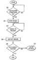
- FIG. 2is an overview flow diagram of one preferred embodiment of the start-stop process.
- the vehicle systemsare constantly monitored in a loop until the conditions are acceptable for stopping the engine at box 200 .
- the engineis then stopped at box 220 .
- a second monitoring loopmonitors the systems of the vehicle at box 240 , as well as any potential inputs by the vehicle operator to signal that the vehicle engine should be restarted.
- the engineis restarted at box 260 .
- the systemchecks to confirm that the engine has restarted successfully at box 280 . If it has, the start-stop process is complete.
- the vehicle systemcan then restart the process and monitor the vehicle again to determine when it is appropriate to stop the vehicle at box 200 . If the engine has not successfully restarted, the method may be aborted at box 300 .
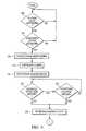
- FIG. 3is a flow diagram illustrating the embodiment of the start-stop process of FIG. 2 in more detail.
- the first monitoring loop at box 200has been broken down into two sub-steps.
- the systems of the vehicleare reviewed at box 202 to confirm that all vehicular conditions are acceptable for stopping the vehicle engine 12 .
- the gear differential 32must be engaged properly.
- the position of the multi-position ignition switch 40is also detected by the powertrain controller 38 so as to verify that the vehicle engine 12 is running.
- Both the engine clutch 16 and the transmission 22are preferably properly engaged.
- the vehicle engine 12is also preferably running. This serves to ensure that the shut down of the vehicle engine 12 will not occur at an inopportune time, such as when the vehicle is traveling on the highway.
- the vehicleis not moving and that the braking system 46 is engaged.
- the engagement of the braking system 46could be via the parking brake, or via pressure on the brake pedal 44 , such as from a vehicle operator in rush-hour traffic.
- the throttle 48 of the vehicleis preferably not engaged.
- the vehicle systems monitoredare those in a preferred embodiment; however, many other vehicle systems could be reviewed in this step.
- this methodalso confirms that the ambient conditions are proper to allow for restart at box 204 of the vehicle engine 12 .
- Some moving parts of the vehicleare typically sensitive to changes in the temperature. If the temperature outside is too cold, the amount of torque from the starter-generator 14 necessary to crank the vehicle engine 12 may increase. In such a situation, it would be preferable for the start-stop method not to be enabled until the ambient temperature is more suited for quick vehicle engine restart.
- the act of stopping the vehicle engine 12 at box 220is further illustrated as sub-steps 222 through 226 in FIG. 3 .
- the starter-generator 14is used to rapidly decelerate the vehicle engine 12 .
- the vehicle engine 12 and its mounting apparatuslike all mechanical systems, have certain resonant frequencies. This is the frequency at which the apparatus will reverberate loudly or otherwise start to shake. This effect, however, will only take place within a small range of frequencies centered on that resonation frequency. When a vehicle engine 12 is decelerated, the rotational frequency of the vehicle engine 12 will likely pass through the resonation frequency.
- the vehicle engine 12When it does, as discussed above, the vehicle engine 12 will begin to shake loudly, causing an audible disturbance to the vehicle operator and affecting the smoothness of the drive.
- the rapid, controlled deceleration of the vehicle engine 12serves to solve this problem.
- the rotational frequency of the vehicle engine 12is within the range of the resonating frequency for a significantly decreased time.
- the decelerationis accomplished by applying a negative torque—a torque in the opposite direction of the running vehicle engine 12 .
- a negative torqueis imparted to the starter-generator 14 .
- the vehicle engine 12 and the starter-generator 14are then linked together through the engine clutch 16 .
- the opposing torquedecelerates the vehicle engine 12 more rapidly than merely applying the braking system 46 to the vehicle engine 12 .
- the engine clutch 16is disengaged at box 224 , cutting the link between the vehicle engine 12 and the starter-generator 14 , and finally the starter-generator rotor 18 is decelerated to an idling speed at box 226 .
- the transmission 28While the vehicle engine 12 is not running, it is important to keep the gearing of the transmission 28 rotating. In fact, most of the clutches of the vehicle, such as the engine clutch 16 , are held closed only by the hydraulics of the transmission 28 . In order to ensure that the engine clutch 16 can function when the vehicle is restarted, the transmission 28 must remain in operation. With the current configuration of the engine, the transmission can be directly connected to the starter-generator 14 , either through the torque converter 22 or via the torque converter bypass clutch 30 . Since the starter-generator 14 continues to run at idle speed, even when the vehicle engine 12 has shut down, the transmission 28 also continues to run.
- the next step of the presently preferred methodis to monitor the systems of the vehicle, at box 240 , for signals or parameters that indicate that the vehicle should restart. These signals could originate from the status of the vehicular systems, at box 242 , as well as from the vehicle operator indicating that the operator wishes the vehicle engine 12 to restart, at box 244 .
- the status of some vehicle systemscan indicate that the vehicle should be restarted in order to avoid any problems with the vehicle or the restart procedure.
- Vehicle systems that may be checked and/or monitoredinclude:
- a time limitcan be set on the length of time the vehicle will remain in shut-down status before the vehicle engine 12 is restarted.
- Temperature of vehicle engineAs before, as the temperature of vehicle engine 12 decreases, so do the temperatures of various vehicle engine 12 parts, such as the engine catalyst and the engine cylinders. The engine catalyst is only effective over a certain temperature, and an ineffective catalyst may cause engine problems. If the temperature of the engine cylinders becomes too cold, there may be excess vehicle exhaust emissions beyond the legal limits. Therefore, another check may be added to signal a restart of the vehicle engine 12 when it reaches a certain threshold temperature.
- the state of charge of the electrical energy storage unit 36is also important. As the starter-generator 14 idles, the transmission 28 , as well as other parts of the vehicle, continues to operate. The energy of the electrical energy storage unit 36 continues to drain. If the state of charge is depleted beyond a certain level, the electrical energy storage unit 36 may not be able to provide enough power to later start the engine 12 . Therefore, the vehicle engine 12 should be restarted if the state of charge of the electrical energy storage unit 36 becomes too depleted to ensure a successful restart.
- the vehicle engine 12should preferably not restart if the vehicle hood 42 is open.
- the hood 42is open, a vehicle operator is working on the vehicle itself. Therefore, it is generally unsafe to start or run the vehicle engine 12 while the hood 42 is open. Therefore, a check may be made by the method to ensure that the vehicle does not start while the hood 42 is open. Such a check could preferably be made with electrical or optical sensors on both the hood 34 of the vehicle and the vehicle frame near the hood 34 .
- the vehicle operatormay, by his actions, also signal that he would like to have the vehicle engine 12 restart, as shown at box 244 .
- the methods that an operator might choose to signal that the engine should restartis to change the brake hydraulic pressure 46 by releasing the brake, changing the gear differential 32 position, or by opening the throttle 48 of the vehicle. These signals would be detected and used to initiate a restart so that the vehicle engine will be fully restarted when the vehicle operator wants to accelerate with little noticeable delay.
- the signals from the vehicle systemsare checked at box 242 after monitoring signals from the vehicle operator at box 244 .
- these two actionscan be completed in an interchangeable order, or they can be done in parallel.
- the operator signalshave been checked first, as well as other embodiments where different elements of each group of tests were done in parallel, or in a mixed serial order.
- the next step of the present inventionis to restart the vehicle engine 12 when a signal is received, as at box 260 .
- This stepconsists of two separate actions, as shown in sub-steps 262 and 264 in FIG. 3 .
- the engine clutch 16is engaged at box 262 , linking together tfe vehicle engine 12 and the starter-generator 14 , which already has some torque.
- the vehicle engine 12is then restarted at box 264 with the starter-generator 14 .
- the torque of the starter-generator 14is imparted to the vehicle engine 12 through the engine clutch 16 , thereby starting the vehicle engine 12 .
- Engine creepis also a concern throughout the restart of the vehicle in the present invention.
- Engine creepis the slow forward movement of a standard vehicle when an operator removes pressure on the brake, but has not yet engaged the accelerator. It is desirable that engine creep be implemented in the present invention as well, as it makes the start-stop procedure less noticeable to the user.
- a small amount of hydraulic pressureis retained in the torque converter 22 , as discussed earlier.
- the powertrain controller 38is configured to monitor the brake hydraulic pressure 46 and to impart a small amount of torque to the vehicle upon release of the brake hydraulic pressure 46 . This small amount of torque is just enough to create the engine creep effect.
- the successful restart of the vehiclealso needs to be verified at box 280 .
- This stepcan be broken into substeps, as illustrated in boxes 282 through 288 in FIG. 3 .
- the first sub-step of this verificationis to determine whether or not the vehicle engine 12 has actually started, at box 282 . This is done by determining the current speed of the vehicle engine 12 , measured in terms of the angular velocity of the vehicle engine 12 , and comparing it to the vehicle engine 12 speed required for engine idling. If the vehicle engine 12 speed has not exceeded the idle speed, the vehicle engine 12 will be tested to see if it has been cranking for longer than a pre-determined length of time at box 284 .
- the state of charge of the electrical energy storage unit 36will be measured and compared to another set level at box 286 to check if said state of charge has gotten too low. Either of these situations could be detrimental to the continued operation of the vehicle, as above. If either of these situations occur, the method will abort at box 300 . If neither is true, then the method will continue to loop until either one of these conditions at box 284 or at box 286 has occurred, or the vehicle engine 12 has successfully started.
- the vehicle engine 12Once it is determined that the vehicle engine 12 has started, it will be further monitored for stalling at box 288 . If the vehicle engine 12 has stalled, operation of the start-stop method ceases and a cold-start strategy is run at box 300 . If the vehicle engine 12 continues to run properly, the method has completed successfully and ends. The vehicle is then ready to begin another start-stop maneuver, at box 200 , at the next opportunity.
- the methodwill abort into an emergency strategy at box 300 .
- the engine clutch 16will first be disengaged at box 302 .
- the starter-generator 14will then be used to give the vehicle a minimal amount of power so that the vehicle can mover to the curb, a “limp to curb” strategy, at box 304 .
- FIG. 4shows one embodiment in a flow diagram of such a method.
- the starter-generator 14is powered up and given at initial torque at box 400 .
- the systems of the vehicleare checked at box 420 to make sure that they are prepared for starting the vehicle engine.
- the engine 12is then started at box 440 .
- the vehicle engine 12is checked to confirm it has successfully restarted at box 460 .
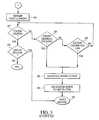
- FIG. 5A more detailed version of this embodiment is set forth in FIG. 5 .
- the systems of the vehicleare checked to verify that the system is in a proper state for an engine start at box 402 .
- Systems that may be checked at this pointinclude whether a gear 32 , the transmission 28 , or the engine clutch 16 are engaged.
- the state of each of these components of the vehicle drive systemindicates whether the vehicle is in a proper state to begin to start the vehicle engine 12 .
- the vehicle engine 12itself should be checked to see if it is already running. If so, then the vehicle does not need to be started. The method should be aborted and the vehicle returned to the beginning of a start-stop strategy.
- the multi-position ignition switch 40should preferably be checked at box 404 before starting the starter-generator 14 .
- a multi-position ignition switch 40can have a pre-designated position to indicate that the vehicle operator wants to start the vehicle engine 12 . This system check at box 404 will verify that the multi-position ignition switch 40 is set to that position, and not allow the vehicle to attempt to start until it is.
- the starter-generator 14is then powered up with a torque at box 400 . By starting the starter-generator 14 at this earlier stage, it allows for a much faster start of the vehicle engine 12 later.
- the vehicle systemsare then evaluated to verify that they are in a proper state for starting the vehicle engine 12 at box 420 .
- the sub-steps of this evaluationare illustrated in boxes 442 through 426 in FIG. 5 .
- Such a methodwould preferably include checking the time that the starter-generator 14 was idling at box 422 as well as the position of the multi-position ignition switch 40 at box 424 .
- the multi-position ignition switch 40would preferably include a position that corresponds to a signal by the vehicle operator to start the vehicle engine 12 . The vehicle systems would then not proceed with the start-up process until the position of the multi-position ignition switch 40 is correct.
- the engine 12is next started at box 440 from the starter-generator 14 .
- the engine clutch 16is engaged in order to bring the moving starter-generator 14 and the vehicle engine 12 in contact, imparting the torque of the starter-generator 14 to the vehicle engine 12 .
- the methodwill verify that the vehicle engine 12 has started correctly at box 460 . This verification is illustrated in boxes 462 and 464 in FIG. 5 . The first part of this verification is to determine whether the engine is running at a speed above idle speed at box 462 . If so, it is determined that the vehicle engine 12 has started correctly, and the cold start method will end.
- the systemwill begin the warm start method, waiting in the first loops for an appropriate signal to shut down the engine at box 200 of FIGS. 2 and 3. If the vehicle engine 12 is not running above the idle speed, the vehicle will then check to see if it has been cranking without starting longer than a pre-determined time at box 464 . If not, the conditions of vehicle engine 12 speed of box 462 and cranking time of box 464 will be continually monitored until the vehicle engine 12 is running at a speed higher than idle speed, or cranking has continued longer than the pre-determined time. If cranking has continued for an unacceptable length of time, the method will abort at box 466 , at which time the starter-generator 14 will shut down, and the vehicle operator may try again to restart the vehicle.
Landscapes
- Engineering & Computer Science (AREA)
- Chemical & Material Sciences (AREA)
- Combustion & Propulsion (AREA)
- Mechanical Engineering (AREA)
- General Engineering & Computer Science (AREA)
- Transportation (AREA)
- Health & Medical Sciences (AREA)
- Life Sciences & Earth Sciences (AREA)
- Atmospheric Sciences (AREA)
- Environmental & Geological Engineering (AREA)
- Toxicology (AREA)
- Control Of Vehicle Engines Or Engines For Specific Uses (AREA)
Abstract
Description
Claims (11)
Priority Applications (5)
| Application Number | Priority Date | Filing Date | Title |
|---|---|---|---|
| US10/159,785US6752741B2 (en) | 2002-05-31 | 2002-05-31 | ISA engine start-stop strategy |
| GB0308499AGB2389151B (en) | 2002-05-31 | 2003-04-14 | ISA engine start-stop strategy |
| DE10323283ADE10323283A1 (en) | 2002-05-31 | 2003-05-21 | Start-stop strategy for an engine with an integrated starter generator |
| FR0306265AFR2840265A1 (en) | 2002-05-31 | 2003-05-23 | PROCESS FOR THE AUTOMATIC OPERATION OF A VEHICLE |
| US10/731,936US7037234B2 (en) | 2002-05-31 | 2003-12-10 | ISA engine start-up strategy |
Applications Claiming Priority (1)
| Application Number | Priority Date | Filing Date | Title |
|---|---|---|---|
| US10/159,785US6752741B2 (en) | 2002-05-31 | 2002-05-31 | ISA engine start-stop strategy |
Related Child Applications (1)
| Application Number | Title | Priority Date | Filing Date |
|---|---|---|---|
| US10/731,936DivisionUS7037234B2 (en) | 2002-05-31 | 2003-12-10 | ISA engine start-up strategy |
Publications (2)
| Publication Number | Publication Date |
|---|---|
| US20030224902A1 US20030224902A1 (en) | 2003-12-04 |
| US6752741B2true US6752741B2 (en) | 2004-06-22 |
Family
ID=22574008
Family Applications (2)
| Application Number | Title | Priority Date | Filing Date |
|---|---|---|---|
| US10/159,785Expired - LifetimeUS6752741B2 (en) | 2002-05-31 | 2002-05-31 | ISA engine start-stop strategy |
| US10/731,936Expired - Fee RelatedUS7037234B2 (en) | 2002-05-31 | 2003-12-10 | ISA engine start-up strategy |
Family Applications After (1)
| Application Number | Title | Priority Date | Filing Date |
|---|---|---|---|
| US10/731,936Expired - Fee RelatedUS7037234B2 (en) | 2002-05-31 | 2003-12-10 | ISA engine start-up strategy |
Country Status (4)
| Country | Link |
|---|---|
| US (2) | US6752741B2 (en) |
| DE (1) | DE10323283A1 (en) |
| FR (1) | FR2840265A1 (en) |
| GB (1) | GB2389151B (en) |
Cited By (8)
| Publication number | Priority date | Publication date | Assignee | Title |
|---|---|---|---|---|
| US20050003930A1 (en)* | 2003-07-02 | 2005-01-06 | Hopper Mark L. | Vehicle control method |
| US20070221421A1 (en)* | 2006-03-23 | 2007-09-27 | Nissan Motor Co., Ltd. | Controlling device and method for hybrid vehicle |
| US20090118078A1 (en)* | 2007-11-07 | 2009-05-07 | Gm Global Technology Operations, Inc. | Method and apparatus for controlling a hybrid powertrain system |
| US20090181821A1 (en)* | 2008-01-14 | 2009-07-16 | Zf Friedrichshafen Ag | Method for operating a drivetrain |
| US20090216430A1 (en)* | 2004-09-23 | 2009-08-27 | Valeo Equipements Electriques Moteur | Automatic vehicle start/stop control method |
| US20110049881A1 (en)* | 2007-12-21 | 2011-03-03 | Marc Ranier | Method and device for the secured control of an alternator-starter assembly coupled to the thermal engine of a vehicle, and corresponding alternator-starter assembly and wire links |
| US9352738B2 (en) | 2013-07-31 | 2016-05-31 | Allison Transmission, Inc. | Dual clutch powertrain architecture |
| US10240571B2 (en) | 2015-06-29 | 2019-03-26 | Cummins, Inc. | Managing automatic stop/start frequency |
Families Citing this family (28)
| Publication number | Priority date | Publication date | Assignee | Title |
|---|---|---|---|---|
| JP3499852B2 (en)* | 2001-12-03 | 2004-02-23 | 本田技研工業株式会社 | Power transmission mechanism |
| US20050011306A1 (en)* | 2003-07-18 | 2005-01-20 | Makoto Kirishima | Driving system with an automatic transmission |
| FR2871205B1 (en)* | 2004-06-03 | 2007-10-05 | Peugeot Citroen Automobiles Sa | WHEEL CLUTCH TRANSMISSION ELEMENT FOR AUTOMOTIVE VEHICLE TRACTION CHAIN, AND MOTOR VEHICLE EQUIPPED WITH SUCH ELEMENT |
| ITBO20040801A1 (en)* | 2004-12-23 | 2005-03-23 | Magneti Marelli Powertrain Spa | METHOD FOR THE MANAGEMENT OF THE "STOP AND START" MODE IN A MOTOR VEHICLE PROVIDED WITH AN INTERNAL COMBUSTION ENGINE. |
| US7823471B2 (en) | 2005-05-31 | 2010-11-02 | Gm Global Technology Operations, Inc. | Method for hybrid vehicle powertrain control |
| DE102006005468B4 (en)* | 2006-02-07 | 2017-09-21 | Zf Friedrichshafen Ag | Method for operating a parallel hybrid drive train of a vehicle |
| DE102006005717A1 (en)* | 2006-02-08 | 2007-08-09 | Bayerische Motoren Werke Ag | Vehicle with catalytic converter, comprises arrangement for switching off engine temporarily when temperature threshold value has been reached |
| DE102006016138B4 (en)* | 2006-04-06 | 2014-11-20 | Robert Bosch Gmbh | Hybrid drive with emergency start option |
| DE102007012012A1 (en)* | 2007-03-13 | 2008-09-18 | Zf Friedrichshafen Ag | Hybrid drive system |
| DE102007030298A1 (en)* | 2007-06-29 | 2009-01-02 | Daimler Ag | Method and device for protecting a starter of a motor vehicle engine |
| DE102007047091A1 (en)* | 2007-10-01 | 2009-04-02 | Robert Bosch Gmbh | Modular functional units for starting and stopping an internal combustion engine |
| WO2009086995A1 (en)* | 2007-12-17 | 2009-07-16 | Zf Friedrichshafen Ag | Method and device for controlling a creep operation of a vehicle with a hybrid drive |
| JP4798154B2 (en)* | 2008-03-06 | 2011-10-19 | 日産自動車株式会社 | Control device for hybrid vehicle |
| US7983812B2 (en)* | 2008-08-04 | 2011-07-19 | Scott Potter & Associates, Llc | Method and apparatus for managing battery power in emergency vehicles |
| EP2199170B9 (en)* | 2008-12-18 | 2012-03-14 | Iveco S.p.A. | Method for the activation and the deactivation of the stop and start function in a vehicle, and relative device |
| DE102009004023B4 (en)* | 2009-01-08 | 2018-07-12 | Knorr-Bremse Systeme für Nutzfahrzeuge GmbH | A method for controlling a start-stop operation of a hybrid drive vehicle and a corresponding vehicle |
| DE102009045886A1 (en)* | 2009-10-21 | 2011-04-28 | Robert Bosch Gmbh | Method and apparatus for improving the restart of a vehicle equipped with start-stop operation |
| DE102009047642A1 (en)* | 2009-12-08 | 2011-06-09 | Robert Bosch Gmbh | Method for positioning an engine |
| DE112010005627B4 (en)* | 2010-06-02 | 2020-12-24 | Toyota Jidosha Kabushiki Kaisha | VEHICLE CONTROL DEVICE AND VEHICLE CONTROL PROCEDURES |
| JP5472004B2 (en)* | 2010-09-21 | 2014-04-16 | 株式会社デンソー | Automatic engine start control device |
| GB2489209B (en)* | 2011-03-15 | 2013-09-04 | Jaguar Cars | Motor vehicle and method of control thereof |
| US8496561B2 (en)* | 2011-07-19 | 2013-07-30 | GM Global Technology Operations LLC | Fluid coupling for a hybrid powertrain system |
| US8894540B2 (en)* | 2012-09-13 | 2014-11-25 | Ford Global Technologies, Llc | Method and apparatus for controlling engine shutdown in hybrid vehicles |
| KR101428251B1 (en)* | 2012-12-06 | 2014-08-07 | 현대자동차주식회사 | Control method for vehicle with dct |
| JP6111077B2 (en)* | 2013-01-17 | 2017-04-05 | 株式会社エフ・シー・シー | Power transmission device |
| JP6295998B2 (en) | 2015-05-12 | 2018-03-20 | 株式会社デンソー | Internal combustion engine restart control device |
| EP3485209B1 (en) | 2016-07-14 | 2021-12-08 | Carrier Corporation | Transport refrigeration system and method of operation |
| CN114687903B (en)* | 2022-03-31 | 2023-05-12 | 东风越野车有限公司 | Start-stop control system and method for extended range automobile engine and hybrid vehicle |
Citations (17)
| Publication number | Priority date | Publication date | Assignee | Title |
|---|---|---|---|---|
| US4607312A (en)* | 1982-08-24 | 1986-08-19 | Barreto Mercado William | Radio control security system for automobile doors, trunk and hood locks and engine power |
| JPS63248936A (en) | 1987-04-03 | 1988-10-17 | Plus:Kk | Automatic stopping and starting device for vehicle |
| US5566774A (en) | 1992-05-15 | 1996-10-22 | Mitsubishi Jidosha Kogyo Kabushiki Kaisha | Operating method for a hybrid vehicle |
| JPH1130139A (en) | 1997-07-09 | 1999-02-02 | Hitachi Ltd | Engine automatic stop / start device |
| JPH11257122A (en) | 1998-03-17 | 1999-09-21 | Honda Motor Co Ltd | Automatic engine stop / start control system for vehicles |
| US6048289A (en)* | 1998-03-30 | 2000-04-11 | Nissan Motor Co., Ltd. | Hybrid vehicle |
| US6176807B1 (en)* | 1998-01-16 | 2001-01-23 | Toyota Jidosha Kabushiki Kaisha | Drive control system for hybrid vehicles |
| US6202776B1 (en) | 1995-08-31 | 2001-03-20 | Isad Electronic Systems Gmbh & Co. Kg | Drive system, especially for a motor vehicle, and method of operating same |
| US20010018903A1 (en)* | 2000-03-06 | 2001-09-06 | Toyota Jidosha Kabushiki Kaisha | Control apparatus for idling stop of internal combustion engine and vehicle with the apparatus mounted thereon |
| JP2002031023A (en) | 2000-07-14 | 2002-01-31 | Mikuni Corp | Pressure detecting device, pressure detecting method, and recording medium |
| JP2002047964A (en)* | 2000-07-31 | 2002-02-15 | Zexel Valeo Climate Control Corp | Idle stop controller for vehicle |
| US6352489B1 (en)* | 1999-03-09 | 2002-03-05 | Honda Giken Kogyo Kabushiki Kaisha | Engine control system for hybrid vehicle |
| US6358180B1 (en)* | 1999-08-16 | 2002-03-19 | Honda Giken Kogyo Kabushiki Kaisha | Engine control system and method |
| US20020049115A1 (en)* | 2000-10-25 | 2002-04-25 | Toyota Jidosha Kabushiki Kaisha | Hybrid vehicle capable of reducing NOx emissions and method of operating same |
| GB2368664A (en) | 2000-10-11 | 2002-05-08 | Ford Global Tech Inc | "Engine braking feel" for an electric motor of a hybrid powertrain |
| US20020074173A1 (en)* | 2000-12-18 | 2002-06-20 | Kazuhiko Morimoto | Automatic stop/ start-up controlling device of an engine |
| US20020163197A1 (en) | 2000-06-16 | 2002-11-07 | Gerhard Koelle | Starter device for an internal combustion engine |
Family Cites Families (7)
| Publication number | Priority date | Publication date | Assignee | Title |
|---|---|---|---|---|
| DE2943563A1 (en)* | 1979-10-27 | 1981-05-07 | Volkswagenwerk Ag | DRIVE, ESPECIALLY FOR MOTOR VEHICLES, WITH AN INTERNAL COMBUSTION ENGINE AND AN AUTOMATIC TRANSMISSION |
| DE2943554A1 (en)* | 1979-10-27 | 1981-05-07 | Volkswagenwerk Ag | HYBRID DRIVE FOR A VEHICLE, IN PARTICULAR MOTOR VEHICLE |
| JPH04121457A (en)* | 1990-09-11 | 1992-04-22 | Zexel Corp | Engine starter device for vehicle with automatic transmission |
| JP3447937B2 (en)* | 1997-11-18 | 2003-09-16 | 本田技研工業株式会社 | Hybrid vehicle |
| JP4682416B2 (en)* | 2000-11-16 | 2011-05-11 | トヨタ自動車株式会社 | Vehicle drive device |
| JP2002257220A (en)* | 2001-03-02 | 2002-09-11 | Jatco Ltd | Control device of automatic transmission |
| US6616569B2 (en)* | 2001-06-04 | 2003-09-09 | General Motors Corporation | Torque control system for a hybrid vehicle with an automatic transmission |
- 2002
- 2002-05-31USUS10/159,785patent/US6752741B2/ennot_activeExpired - Lifetime
- 2003
- 2003-04-14GBGB0308499Apatent/GB2389151B/ennot_activeExpired - Fee Related
- 2003-05-21DEDE10323283Apatent/DE10323283A1/ennot_activeWithdrawn
- 2003-05-23FRFR0306265Apatent/FR2840265A1/ennot_activeWithdrawn
- 2003-12-10USUS10/731,936patent/US7037234B2/ennot_activeExpired - Fee Related
Patent Citations (17)
| Publication number | Priority date | Publication date | Assignee | Title |
|---|---|---|---|---|
| US4607312A (en)* | 1982-08-24 | 1986-08-19 | Barreto Mercado William | Radio control security system for automobile doors, trunk and hood locks and engine power |
| JPS63248936A (en) | 1987-04-03 | 1988-10-17 | Plus:Kk | Automatic stopping and starting device for vehicle |
| US5566774A (en) | 1992-05-15 | 1996-10-22 | Mitsubishi Jidosha Kogyo Kabushiki Kaisha | Operating method for a hybrid vehicle |
| US6202776B1 (en) | 1995-08-31 | 2001-03-20 | Isad Electronic Systems Gmbh & Co. Kg | Drive system, especially for a motor vehicle, and method of operating same |
| JPH1130139A (en) | 1997-07-09 | 1999-02-02 | Hitachi Ltd | Engine automatic stop / start device |
| US6176807B1 (en)* | 1998-01-16 | 2001-01-23 | Toyota Jidosha Kabushiki Kaisha | Drive control system for hybrid vehicles |
| JPH11257122A (en) | 1998-03-17 | 1999-09-21 | Honda Motor Co Ltd | Automatic engine stop / start control system for vehicles |
| US6048289A (en)* | 1998-03-30 | 2000-04-11 | Nissan Motor Co., Ltd. | Hybrid vehicle |
| US6352489B1 (en)* | 1999-03-09 | 2002-03-05 | Honda Giken Kogyo Kabushiki Kaisha | Engine control system for hybrid vehicle |
| US6358180B1 (en)* | 1999-08-16 | 2002-03-19 | Honda Giken Kogyo Kabushiki Kaisha | Engine control system and method |
| US20010018903A1 (en)* | 2000-03-06 | 2001-09-06 | Toyota Jidosha Kabushiki Kaisha | Control apparatus for idling stop of internal combustion engine and vehicle with the apparatus mounted thereon |
| US20020163197A1 (en) | 2000-06-16 | 2002-11-07 | Gerhard Koelle | Starter device for an internal combustion engine |
| JP2002031023A (en) | 2000-07-14 | 2002-01-31 | Mikuni Corp | Pressure detecting device, pressure detecting method, and recording medium |
| JP2002047964A (en)* | 2000-07-31 | 2002-02-15 | Zexel Valeo Climate Control Corp | Idle stop controller for vehicle |
| GB2368664A (en) | 2000-10-11 | 2002-05-08 | Ford Global Tech Inc | "Engine braking feel" for an electric motor of a hybrid powertrain |
| US20020049115A1 (en)* | 2000-10-25 | 2002-04-25 | Toyota Jidosha Kabushiki Kaisha | Hybrid vehicle capable of reducing NOx emissions and method of operating same |
| US20020074173A1 (en)* | 2000-12-18 | 2002-06-20 | Kazuhiko Morimoto | Automatic stop/ start-up controlling device of an engine |
Non-Patent Citations (1)
| Title |
|---|
| UK Search Report, Sep. 11, 2003. |
Cited By (16)
| Publication number | Priority date | Publication date | Assignee | Title |
|---|---|---|---|---|
| US6926639B2 (en)* | 2003-07-02 | 2005-08-09 | Visteon Global Technologies, Inc. | Vehicle control method |
| US20050003930A1 (en)* | 2003-07-02 | 2005-01-06 | Hopper Mark L. | Vehicle control method |
| US8175791B2 (en) | 2004-09-23 | 2012-05-08 | Valeo Equipements Electriques Moteur | Automatic vehicle start/stop control method |
| US20090216430A1 (en)* | 2004-09-23 | 2009-08-27 | Valeo Equipements Electriques Moteur | Automatic vehicle start/stop control method |
| US8002059B2 (en)* | 2006-03-23 | 2011-08-23 | Nissan Motor Co., Ltd. | Controlling device and method for hybrid vehicle |
| US20070221421A1 (en)* | 2006-03-23 | 2007-09-27 | Nissan Motor Co., Ltd. | Controlling device and method for hybrid vehicle |
| US8631891B2 (en) | 2007-11-07 | 2014-01-21 | GM Global Technology Operations LLC | Method and apparatus for controlling a hybrid powertrain system |
| US8271173B2 (en)* | 2007-11-07 | 2012-09-18 | GM Global Technology Operations LLC | Method and apparatus for controlling a hybrid powertrain system |
| US20090118078A1 (en)* | 2007-11-07 | 2009-05-07 | Gm Global Technology Operations, Inc. | Method and apparatus for controlling a hybrid powertrain system |
| US20110049881A1 (en)* | 2007-12-21 | 2011-03-03 | Marc Ranier | Method and device for the secured control of an alternator-starter assembly coupled to the thermal engine of a vehicle, and corresponding alternator-starter assembly and wire links |
| US8583321B2 (en)* | 2007-12-21 | 2013-11-12 | Valeo Equipments Electriqyues Moteur | Method and device for secured control of alternator-starter assembly coupled to thermal engine of vehicle, and corresponding alternator-starter assembly and wire links |
| US20090181821A1 (en)* | 2008-01-14 | 2009-07-16 | Zf Friedrichshafen Ag | Method for operating a drivetrain |
| US8388493B2 (en)* | 2008-01-14 | 2013-03-05 | Zf Friedrichshafen, Ag | Method for operating a drivetrain |
| US9352738B2 (en) | 2013-07-31 | 2016-05-31 | Allison Transmission, Inc. | Dual clutch powertrain architecture |
| US10240571B2 (en) | 2015-06-29 | 2019-03-26 | Cummins, Inc. | Managing automatic stop/start frequency |
| US10731619B2 (en) | 2015-06-29 | 2020-08-04 | Cummins, Inc. | Managing automatic stop/start frequency |
Also Published As
| Publication number | Publication date |
|---|---|
| GB2389151B (en) | 2004-07-21 |
| US20040127327A1 (en) | 2004-07-01 |
| GB0308499D0 (en) | 2003-05-21 |
| DE10323283A1 (en) | 2004-03-25 |
| US20030224902A1 (en) | 2003-12-04 |
| GB2389151A (en) | 2003-12-03 |
| US7037234B2 (en) | 2006-05-02 |
| FR2840265A1 (en) | 2003-12-05 |
Similar Documents
| Publication | Publication Date | Title |
|---|---|---|
| US6752741B2 (en) | ISA engine start-stop strategy | |
| JP3743421B2 (en) | Vehicle control device | |
| US7823668B2 (en) | Control device for a hybrid electric vehicle | |
| JP6642459B2 (en) | Vehicle control device | |
| US10137882B2 (en) | Hybrid electric vehicle and method of controlling the same | |
| JP5001839B2 (en) | How to prohibit the automatic stop command of the vehicle's heat engine in a traffic jam | |
| JP2000274273A (en) | Automatic restart / restart system for vehicle engines | |
| KR102586334B1 (en) | Apparatus and method for controlling starting of engine for vehicle | |
| JPH1182260A (en) | On-vehicle hybrid drive device | |
| JP2000257465A (en) | Engine control device for hybrid vehicle | |
| US7500458B2 (en) | Method for operating motor vehicle having an internal combustion engine | |
| JPH0924752A (en) | Control device for vehicle drive unit | |
| JP3596213B2 (en) | Engine control device | |
| JP2004324446A (en) | Engine starter | |
| JP2002213498A (en) | In-vehicle equipment drive | |
| JP2001224104A (en) | Hybrid vehicle control device | |
| JP4135688B2 (en) | Hybrid vehicle clutch slip detection method | |
| US20100305800A1 (en) | Method and apparatus for detecting engine firing in a hybrid powertrain system | |
| JP2001206088A (en) | Hybrid vehicle control device | |
| KR102586335B1 (en) | Apparatus and method for controlling starting of engine for vehicle | |
| JP2000001133A (en) | Hybrid vehicle control device | |
| CN102529855A (en) | ISS system and method of controlling vehicle engine | |
| WO2022064591A1 (en) | Method for controlling internal combustion engine, and device for controlling internal combustion engine | |
| JP3196512B2 (en) | Automatic engine start / stop device | |
| JP2004176623A (en) | Engine power transmission member abnormality determination device |
Legal Events
| Date | Code | Title | Description |
|---|---|---|---|
| STCF | Information on status: patent grant | Free format text:PATENTED CASE | |
| CC | Certificate of correction | ||
| AS | Assignment | Owner name:VISTEON GLOBAL TECHNOLOGIES, INC., MICHIGAN Free format text:ASSIGNMENT OF ASSIGNORS INTEREST;ASSIGNORS:KAHLON, GURINDER S.;KLOCINSKI, JAMES J.;LIU, NING;AND OTHERS;REEL/FRAME:018961/0150;SIGNING DATES FROM 20020819 TO 20020822 | |
| FPAY | Fee payment | Year of fee payment:4 | |
| AS | Assignment | Owner name:JPMORGAN CHASE BANK, N.A., AS ADMINISTRATIVE AGENT Free format text:SECURITY AGREEMENT;ASSIGNOR:VISTEON GLOBAL TECHNOLOGIES, INC.;REEL/FRAME:020497/0733 Effective date:20060613 | |
| AS | Assignment | Owner name:JPMORGAN CHASE BANK, TEXAS Free format text:SECURITY INTEREST;ASSIGNOR:VISTEON GLOBAL TECHNOLOGIES, INC.;REEL/FRAME:022368/0001 Effective date:20060814 Owner name:JPMORGAN CHASE BANK,TEXAS Free format text:SECURITY INTEREST;ASSIGNOR:VISTEON GLOBAL TECHNOLOGIES, INC.;REEL/FRAME:022368/0001 Effective date:20060814 | |
| AS | Assignment | Owner name:WILMINGTON TRUST FSB, AS ADMINISTRATIVE AGENT, MIN Free format text:ASSIGNMENT OF SECURITY INTEREST IN PATENTS;ASSIGNOR:JPMORGAN CHASE BANK, N.A., AS ADMINISTRATIVE AGENT;REEL/FRAME:022575/0186 Effective date:20090415 Owner name:WILMINGTON TRUST FSB, AS ADMINISTRATIVE AGENT,MINN Free format text:ASSIGNMENT OF SECURITY INTEREST IN PATENTS;ASSIGNOR:JPMORGAN CHASE BANK, N.A., AS ADMINISTRATIVE AGENT;REEL/FRAME:022575/0186 Effective date:20090415 | |
| AS | Assignment | Owner name:THE BANK OF NEW YORK MELLON, AS ADMINISTRATIVE AGE Free format text:ASSIGNMENT OF PATENT SECURITY INTEREST;ASSIGNOR:JPMORGAN CHASE BANK, N.A., A NATIONAL BANKING ASSOCIATION;REEL/FRAME:022974/0057 Effective date:20090715 | |
| AS | Assignment | Owner name:VISTEON GLOBAL TECHNOLOGIES, INC., MICHIGAN Free format text:RELEASE BY SECURED PARTY AGAINST SECURITY INTEREST IN PATENTS RECORDED AT REEL 022974 FRAME 0057;ASSIGNOR:THE BANK OF NEW YORK MELLON;REEL/FRAME:025095/0711 Effective date:20101001 | |
| AS | Assignment | Owner name:VISTEON GLOBAL TECHNOLOGIES, INC., MICHIGAN Free format text:RELEASE BY SECURED PARTY AGAINST SECURITY INTEREST IN PATENTS RECORDED AT REEL 022575 FRAME 0186;ASSIGNOR:WILMINGTON TRUST FSB, AS ADMINISTRATIVE AGENT;REEL/FRAME:025105/0201 Effective date:20101001 | |
| AS | Assignment | Owner name:MORGAN STANLEY SENIOR FUNDING, INC., AS AGENT, NEW Free format text:SECURITY AGREEMENT;ASSIGNORS:VISTEON CORPORATION;VC AVIATION SERVICES, LLC;VISTEON ELECTRONICS CORPORATION;AND OTHERS;REEL/FRAME:025241/0317 Effective date:20101007 Owner name:MORGAN STANLEY SENIOR FUNDING, INC., AS AGENT, NEW Free format text:SECURITY AGREEMENT (REVOLVER);ASSIGNORS:VISTEON CORPORATION;VC AVIATION SERVICES, LLC;VISTEON ELECTRONICS CORPORATION;AND OTHERS;REEL/FRAME:025238/0298 Effective date:20101001 | |
| AS | Assignment | Owner name:VC AVIATION SERVICES, LLC, MICHIGAN Free format text:RELEASE BY SECURED PARTY AGAINST SECURITY INTEREST IN PATENTS ON REEL 025241 FRAME 0317;ASSIGNOR:MORGAN STANLEY SENIOR FUNDING, INC.;REEL/FRAME:026178/0412 Effective date:20110406 Owner name:VISTEON INTERNATIONAL HOLDINGS, INC., MICHIGAN Free format text:RELEASE BY SECURED PARTY AGAINST SECURITY INTEREST IN PATENTS ON REEL 025241 FRAME 0317;ASSIGNOR:MORGAN STANLEY SENIOR FUNDING, INC.;REEL/FRAME:026178/0412 Effective date:20110406 Owner name:VISTEON INTERNATIONAL BUSINESS DEVELOPMENT, INC., Free format text:RELEASE BY SECURED PARTY AGAINST SECURITY INTEREST IN PATENTS ON REEL 025241 FRAME 0317;ASSIGNOR:MORGAN STANLEY SENIOR FUNDING, INC.;REEL/FRAME:026178/0412 Effective date:20110406 Owner name:VISTEON ELECTRONICS CORPORATION, MICHIGAN Free format text:RELEASE BY SECURED PARTY AGAINST SECURITY INTEREST IN PATENTS ON REEL 025241 FRAME 0317;ASSIGNOR:MORGAN STANLEY SENIOR FUNDING, INC.;REEL/FRAME:026178/0412 Effective date:20110406 Owner name:VISTEON SYSTEMS, LLC, MICHIGAN Free format text:RELEASE BY SECURED PARTY AGAINST SECURITY INTEREST IN PATENTS ON REEL 025241 FRAME 0317;ASSIGNOR:MORGAN STANLEY SENIOR FUNDING, INC.;REEL/FRAME:026178/0412 Effective date:20110406 Owner name:VISTEON GLOBAL TECHNOLOGIES, INC., MICHIGAN Free format text:RELEASE BY SECURED PARTY AGAINST SECURITY INTEREST IN PATENTS ON REEL 025241 FRAME 0317;ASSIGNOR:MORGAN STANLEY SENIOR FUNDING, INC.;REEL/FRAME:026178/0412 Effective date:20110406 Owner name:VISTEON CORPORATION, MICHIGAN Free format text:RELEASE BY SECURED PARTY AGAINST SECURITY INTEREST IN PATENTS ON REEL 025241 FRAME 0317;ASSIGNOR:MORGAN STANLEY SENIOR FUNDING, INC.;REEL/FRAME:026178/0412 Effective date:20110406 Owner name:VISTEON EUROPEAN HOLDING, INC., MICHIGAN Free format text:RELEASE BY SECURED PARTY AGAINST SECURITY INTEREST IN PATENTS ON REEL 025241 FRAME 0317;ASSIGNOR:MORGAN STANLEY SENIOR FUNDING, INC.;REEL/FRAME:026178/0412 Effective date:20110406 Owner name:VISTEON GLOBAL TREASURY, INC., MICHIGAN Free format text:RELEASE BY SECURED PARTY AGAINST SECURITY INTEREST IN PATENTS ON REEL 025241 FRAME 0317;ASSIGNOR:MORGAN STANLEY SENIOR FUNDING, INC.;REEL/FRAME:026178/0412 Effective date:20110406 | |
| FPAY | Fee payment | Year of fee payment:8 | |
| AS | Assignment | Owner name:CITIBANK., N.A., AS ADMINISTRATIVE AGENT, NEW YORK Free format text:SECURITY INTEREST;ASSIGNORS:VISTEON CORPORATION, AS GRANTOR;VISTEON GLOBAL TECHNOLOGIES, INC., AS GRANTOR;REEL/FRAME:032713/0065 Effective date:20140409 | |
| AS | Assignment | Owner name:VISTEON ELECTRONICS CORPORATION, MICHIGAN Free format text:RELEASE OF SECURITY INTEREST IN INTELLECTUAL PROPERTY;ASSIGNOR:MORGAN STANLEY SENIOR FUNDING, INC.;REEL/FRAME:033107/0717 Effective date:20140409 Owner name:VISTEON GLOBAL TREASURY, INC., MICHIGAN Free format text:RELEASE OF SECURITY INTEREST IN INTELLECTUAL PROPERTY;ASSIGNOR:MORGAN STANLEY SENIOR FUNDING, INC.;REEL/FRAME:033107/0717 Effective date:20140409 Owner name:VISTEON GLOBAL TECHNOLOGIES, INC., MICHIGAN Free format text:RELEASE OF SECURITY INTEREST IN INTELLECTUAL PROPERTY;ASSIGNOR:MORGAN STANLEY SENIOR FUNDING, INC.;REEL/FRAME:033107/0717 Effective date:20140409 Owner name:VISTEON EUROPEAN HOLDINGS, INC., MICHIGAN Free format text:RELEASE OF SECURITY INTEREST IN INTELLECTUAL PROPERTY;ASSIGNOR:MORGAN STANLEY SENIOR FUNDING, INC.;REEL/FRAME:033107/0717 Effective date:20140409 Owner name:VISTEON SYSTEMS, LLC, MICHIGAN Free format text:RELEASE OF SECURITY INTEREST IN INTELLECTUAL PROPERTY;ASSIGNOR:MORGAN STANLEY SENIOR FUNDING, INC.;REEL/FRAME:033107/0717 Effective date:20140409 Owner name:VC AVIATION SERVICES, LLC, MICHIGAN Free format text:RELEASE OF SECURITY INTEREST IN INTELLECTUAL PROPERTY;ASSIGNOR:MORGAN STANLEY SENIOR FUNDING, INC.;REEL/FRAME:033107/0717 Effective date:20140409 Owner name:VISTEON CORPORATION, MICHIGAN Free format text:RELEASE OF SECURITY INTEREST IN INTELLECTUAL PROPERTY;ASSIGNOR:MORGAN STANLEY SENIOR FUNDING, INC.;REEL/FRAME:033107/0717 Effective date:20140409 Owner name:VISTEON INTERNATIONAL BUSINESS DEVELOPMENT, INC., Free format text:RELEASE OF SECURITY INTEREST IN INTELLECTUAL PROPERTY;ASSIGNOR:MORGAN STANLEY SENIOR FUNDING, INC.;REEL/FRAME:033107/0717 Effective date:20140409 Owner name:VISTEON INTERNATIONAL HOLDINGS, INC., MICHIGAN Free format text:RELEASE OF SECURITY INTEREST IN INTELLECTUAL PROPERTY;ASSIGNOR:MORGAN STANLEY SENIOR FUNDING, INC.;REEL/FRAME:033107/0717 Effective date:20140409 | |
| AS | Assignment | Owner name:VISTEON GLOBAL TECHNOLOGIES, MICHIGAN Free format text:RELEASE OF SECURITY INTEREST IN SPECIFIED PATENTS;ASSIGNOR:CITIBANK, N.A.;REEL/FRAME:034874/0025 Effective date:20150202 Owner name:VISTEON CORPORATION, MICHIGAN Free format text:RELEASE OF SECURITY INTEREST IN SPECIFIED PATENTS;ASSIGNOR:CITIBANK, N.A.;REEL/FRAME:034874/0025 Effective date:20150202 | |
| AS | Assignment | Owner name:GODO KAISHA IP BRIDGE 1, JAPAN Free format text:ASSIGNMENT OF ASSIGNORS INTEREST;ASSIGNOR:VISTEON GLOBAL TECHNOLOGIES INC.;REEL/FRAME:035421/0739 Effective date:20150213 | |
| FPAY | Fee payment | Year of fee payment:12 | |
| AS | Assignment | Owner name:MOBILE AUTOMOTIVE TECHNOLOGIES, LLC, ALABAMA Free format text:ASSIGNMENT OF ASSIGNORS INTEREST;ASSIGNOR:GODO KAISHA IP BRIDGE;REEL/FRAME:043463/0223 Effective date:20160902 Owner name:MICHIGAN MOTOR TECHNOLOGIES LLC, MICHIGAN Free format text:ASSIGNMENT OF ASSIGNORS INTEREST;ASSIGNOR:MOBILE AUTOMOTIVE TECHNOLOGIES, LLC;REEL/FRAME:043463/0881 Effective date:20170828 Owner name:MOBILE AUTOMOTIVE TECHNOLOGIES, LLC, ALABAMA Free format text:ASSIGNMENT OF ASSIGNORS INTEREST;ASSIGNOR:GODO KAISHA IP BRIDGE;REEL/FRAME:043843/0821 Effective date:20161102 |