US6752713B2 - Cool air ventilation system - Google Patents
Cool air ventilation systemDownload PDFInfo
- Publication number
- US6752713B2 US6752713B2US10/410,319US41031903AUS6752713B2US 6752713 B2US6752713 B2US 6752713B2US 41031903 AUS41031903 AUS 41031903AUS 6752713 B2US6752713 B2US 6752713B2
- Authority
- US
- United States
- Prior art keywords
- air
- space
- attic
- handling apparatus
- building
- Prior art date
- Legal status (The legal status is an assumption and is not a legal conclusion. Google has not performed a legal analysis and makes no representation as to the accuracy of the status listed.)
- Expired - Lifetime
Links
- 238000009423ventilationMethods0.000titleclaimsdescription26
- 238000001816coolingMethods0.000claimsabstractdescription9
- 239000012528membraneSubstances0.000claimsdescription5
- 238000004378air conditioningMethods0.000claimsdescription4
- 229920002457flexible plasticPolymers0.000claimsdescription4
- 239000002085irritantSubstances0.000abstractdescription3
- 231100000021irritantToxicity0.000abstractdescription3
- 239000000356contaminantSubstances0.000description7
- 230000036541healthEffects0.000description7
- 230000008901benefitEffects0.000description4
- 230000009467reductionEffects0.000description4
- 239000000428dustSubstances0.000description3
- 235000019645odorNutrition0.000description3
- 239000002245particleSubstances0.000description3
- 238000013459approachMethods0.000description2
- 238000011109contaminationMethods0.000description2
- 238000005516engineering processMethods0.000description2
- 238000012423maintenanceMethods0.000description2
- 238000005067remediationMethods0.000description2
- 230000001932seasonal effectEffects0.000description2
- 239000007787solidSubstances0.000description2
- 206010020751HypersensitivityDiseases0.000description1
- 230000002009allergenic effectEffects0.000description1
- 208000026935allergic diseaseDiseases0.000description1
- 230000007815allergyEffects0.000description1
- 208000006673asthmaDiseases0.000description1
- 238000009435building constructionMethods0.000description1
- 239000004566building materialSubstances0.000description1
- 238000004134energy conservationMethods0.000description1
- 230000007613environmental effectEffects0.000description1
- 230000005484gravityEffects0.000description1
- 230000007407health benefitEffects0.000description1
- 230000008595infiltrationEffects0.000description1
- 238000001764infiltrationMethods0.000description1
- 239000000463materialSubstances0.000description1
- 230000007246mechanismEffects0.000description1
- 239000000203mixtureSubstances0.000description1
- 230000035515penetrationEffects0.000description1
- 229920003023plasticPolymers0.000description1
- 239000004033plasticSubstances0.000description1
- 239000002985plastic filmSubstances0.000description1
- 229910052704radonInorganic materials0.000description1
- SYUHGPGVQRZVTB-UHFFFAOYSA-Nradon atomChemical compound[Rn]SYUHGPGVQRZVTB-UHFFFAOYSA-N0.000description1
Images

Classifications
- F—MECHANICAL ENGINEERING; LIGHTING; HEATING; WEAPONS; BLASTING
- F24—HEATING; RANGES; VENTILATING
- F24F—AIR-CONDITIONING; AIR-HUMIDIFICATION; VENTILATION; USE OF AIR CURRENTS FOR SCREENING
- F24F7/00—Ventilation
- F24F7/04—Ventilation with ducting systems, e.g. by double walls; with natural circulation
- F24F7/06—Ventilation with ducting systems, e.g. by double walls; with natural circulation with forced air circulation, e.g. by fan positioning of a ventilator in or against a conduit
- F24F7/065—Ventilation with ducting systems, e.g. by double walls; with natural circulation with forced air circulation, e.g. by fan positioning of a ventilator in or against a conduit fan combined with single duct; mounting arrangements of a fan in a duct
Definitions
- the present inventionrelates to the cooling of a single or multi-floor building structure on the size of a residence, or a similar small commercial, office, or apartment type building.
- the typical building structure that the cool air ventilation system invention would be used withinwould contain a closed off habitable indoor living space, separating a crawl space below and an attic space above.
- the cool air in the crawl spaceis captured by an applicable system of ducts, the cool air moved by the means of a controlled fan/blower air handling apparatus, and the cool air moved vertically by duct or air chase into the attic space.
- the hot air temperature within the atticis reduced by the positive cool fresh air flow drawn from the crawl space, creating an efficient means of lowering the heat load on the building, thus saving cooling costs, and related energy needs.
- the present inventionalso addresses a configuration of the system with a reduction and possible omission of ducts in the crawl space and attic space. In this arrangement, a vertical duct/air chase from the crawl space to the attic with a controlled fan apparatus would be used
- the movement of air within the crawl space, cellar, basement, and attic airis not blocked off from the indoor living space. That same air is allowed to infiltrate the habitable portion of the building. That same air could be contaminated by the odors, irritants, and contaminants within the crawl space or attic space; depending on how the air was being used.
- Some prior systemsmay use the building cool air combined with the cool air produced from an air conditioning system or heat exchanger.
- the cool air ventilation system inventiondoes not mix cool air from the crawl space, cellar, or basement space with other building cooling systems.
- the present inventionwas designed in such a way as to be applicable to a plurality of new and existing building construction means.
- the present inventionwas also designed in a simple means to reduce in place costs and operating costs. Where as other approaches are lacking in one or any combination of the following-cost effective, health benefits, simplicity, and performance.
- the cool air ventilation system inventionwould reduce the crawl space contaminants due to the positive flow of fresh air and reducing the infiltration of the irritable contaminants into the habitable portion of the building.
- the described cool air ventilation system inventionmay also be utilized by the building inhabitants during the off season colder months, as needed to create fresh air to reduce the crawl space contaminants.
- the United States Environmental Protection Agencyhas two extensive published articles relating to mold problems in the U.S. The two articles are, “A Brief Guide to Mold, Moisture, and Your Home”, and “Mold Remediation in Schools and Commercial Buildings”. Both articles interact and are applicable to most buildings. There are several health issues involved, such as asthma and allergy problems which causes suffering to millions of people. One of the key items the EPA expressed several times was that “Moisture Control is the Key to Mold Control”.
- the EPA article, “Mold Remediation in Schools and Commercial Buildings”, mentioned aboveincludes the following statement, “Molds gradually destroy the things they grow on. Prevent damage to building materials and furnishings, save money, and avoid potential health risks by controlling moisture and eliminating mold growth”.
- the cool air ventilation system inventionhelps to reduce moisture in both the habitable indoor portion of the building, and crawl space, cellar, or basement, and mold is reduced creating healthier living conditions, which helps to save health care expenses. Reduction of moisture in the crawl space reduces mold, which attacks costly structural building components, saving the building owner maintenance costs.
- the United States Department of Energy-Office of Building Technology State and Community Programs publication, “Installing and Using a Whole House Fan”,relates to cost saving of a whole house fan and health issues.
- the disadvantages of this technologyis the outside contaminants are pulled into the habitable indoor living space of the building through open windows. The building inhabitants are then subject to allergenic pollen and dust.
- the cool air ventilation systemdoes not contaminate the building structure indoor living space. It does not have an unattractive open hole in the indoor ceiling to winterize.
- a cellar or basement areamay be utilized for drawing cool fresh air through openings; the air flow may be filtered as needed with an air filter in an air filter housing frame.
- the present inventionmay act on it's own for cooling a building. In other areas of the world, it may be an advantage to also include additional air conditioning equipment means within the building structure.
- the present inventionreduces the heat load on the building structure. This is an advantage as the additional air conditioning equipment can be downsized, helping to offset equipment, maintenance, operation, and overall cooling energy costs.
- the described cool air ventilation system inventionreduces the building heat load, reduces building cooling costs, helps to save natural resources used to create energy, and reduces resultant contamination, provides healthier living conditions for the building inhabitants, which helps to save health care expenses, and enhances the longevity of some building components subject to hot attic heat and mold in the crawl space.
- the present inventionrelates to a reduction of the heat load on a building structure such as a residence type building. This is accomplished by utilizing the coolness found in the lowest shaded closed off space of a building. Fresh air enters at the exterior wall vents or openings at the lower level, the air moves though the lower level circulated vertically and disbursed into and out of the exterior vented attic space. The positive cool airflow through the hot attic space reduces the hot attic heat, and thus reduces the heat load on the building.
- a fan/blower air handling apparatus with applicable ductsis a means of creating the positive airflow from the lowest space of the building to the attic space. Reducing the building heat load in this means is cost effective and allows energy conservation, and savings.
- Another object of the cool air ventilation system inventionis to create a healthier means to utilize the low-level cool air space, without circulating that same air into the building indoor living space of the building.
- the building structureis split into three spaces, a closed off habitable indoor living space, separating a low level crawl space, cellar or basement space, and a upper attic space.
- the upper attic space and the lower crawl spaceis connected with a solid duct or a combination air chase constructed in such a means to prevent air penetration into the habitable indoor living space. This means prevents odors, irritants and contaminated air from flowing into the habitable indoor living space and thus helps save health related expenses for the building inhabitants.
- the cool air ventilation system invention system fan/blower air handling apparatusis controlled by a plurality of means for efficient operation and benefit for the building inhabitant.
- the applicable control meansmay include any one or combination of the following, an off-on switch, a temperature operating switch, an exterior solar type off-on switch, a humidistat, and an adjustable intermittent off-on timer switch.
- the humidistatwould be utilized to prevent damp air from being pulled into the building structure.
- the present cool air ventilation system inventionutilizes the air drawn from a cooler source of supply, and therefore enhances an efficient means of attic ventilation and reduces exposure to contaminants.
- Another object of the present cool air ventilation system inventionwould be to enhance the reduction of dust particles in the moving air from the crawl space, cellar or basement spaces to the attic space.
- a means to help prevent movement of dust particleswould be to utilize an air filter housing and air filter at the fan/blower air handling apparatus, at the air chase, and at exterior vents, and window openings.
- the earth covered crawl space, or cellarcan be covered with a plastic flexible sheet membrane material.
- the cellar or basement floorcan be covered with a concrete floor.
- the described cool air ventilation system inventionreduces the building heat load, reduces building cooling costs, helps to save natural resources used to create energy, and reduces resultant contamination, provides healthier living conditions for the building inhabitants, which helps to prevent health care expenses, and enhances the longevity of some building components subject to hot attic heat and mold in the crawl space.
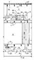
- FIG. 1is a partial section of a building structure of the present invention, showing an arrangement of an attic space above a single floor indoor living space above a crawl space, with ducts, blower air handling apparatus and vents.
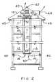
- FIG. 2is a building structure section of the present invention showing an arrangement of an attic space above multi-floors indoor living space over a cellar or basement space, with air chase, fan air handling device, and a combination of building vents.
- FIG. 1is a partial section of a building structure showing an attic space 9 over an indoor living space 12 over a crawl space 16 .
- FIG. 1is further defined with an attic space 9 with roof components 10 , the indoor living space 12 , with ceiling components 11 , with floor components 13 , the crawl space 16 with an earth floor 14 covered with a flexible plastic type membrane covering 15 .
- FIG. 1is further defined with a duct system means, starting in the crawl space with a duct 20 , supplied with perforated, slotted or other means to allow openings to receive air flow, with a duct hanger means 26 to elevate the duct 20 above the covered floor 14 , with a duct connection 22 , with a vertical sealed or solid duct 23 , in an air chase 17 , with an attic perforated duct means 24 , duct connections means 22 to a blower apparatus 30 , and a duct hanger means 26 to elevate the duct 24 if needed in the attic space 9 .
- a duct system meansstarting in the crawl space with a duct 20 , supplied with perforated, slotted or other means to allow openings to receive air flow, with a duct hanger means 26 to elevate the duct 20 above the covered floor 14 , with a duct connection 22 , with a vertical sealed or solid duct 23 , in an air chase 17 , with an attic perforated duct means 24 ,
- FIG. 1is further defined with a blower air handling apparatus 30 , an air filter housing and air filter 31 , with a service door 32 , a back flow damper 33 , a blower device 34 , and an electrical control connection means 35 .
- FIG. 1is further defined with a ventilation vent 40 shown in wall beyond, and a ridge vent 42 .
- air flow directional arrows 50show the direction of air flow when the blower air handling apparatus is in an operational mode.
- the blower apparatus 30would be electrically activated turning on the blower 34 , the blower would start pulling air from the crawl space, fresh air would enter the crawl space through the ventilation vent 40 , the air would then flow through the cool crawl space 16 , be captured or drawn into the crawl space duct 20 , then moved vertically upward in a closed duct 23 , then the air would be pulled through the blower air handling apparatus 30 , as the air is pulled through the blower apparatus it would pass through an air filter 31 , the air then forced outward into the attic duct system 24 , the cool air would then exit the attic duct system flowing into the attic space 9 , and then exit the building through the attic exterior ventilation vent noted as 42 .
- the air chase 17 shown in FIG. 1is a means to architecturally house the vertical duct 23 . In some building structures the air chase may be omitted pending the needs of the building owner.
- FIG. 2is a section of a multi-floor building structure applicable to the cool air ventilation invention with an arrangement of a fan and an air chase or to include a duct plenum, an attic above, and a cellar or basement below, and to further show the versatility of the invention.
- this building arrangementthe ducts in the crawl space and the attic space as shown in FIG. 1 have been omitted.
- FIG. 2is further defined with an attic space 9 with roof components 10 , the indoor living space 12 , with ceiling components 11 , with elevated floor components 13 , the cellar or basement space 18 with an earth base covered with any combination of flexible plastic sheet membrane cover or concrete floor 19 .
- FIG. 2is further defined with a mounted fan apparatus in the attic, with a control connection means 35 , and a frame housing 36 , a connected mounting flange frame 38 , a back flow damper means 33 , which is operated as defined in FIG. 1 .
- FIG. 2is further defined with exterior ventilation vents or openings 40 , in the cellar or basement space 18 , a combination of applicable ventilation vent means are shown in the attic space 9 , which would include a ridge vent 42 , a gable end vent 43 , a dormer vent 44 , an overhang soffit vent 45 .
- FIG. 2is further defined with an air filter housing and air filter shown at the bottom of the air chase opening 17 in the cellar or basement 18 , and also may be installed at the exterior vents or openings 40 .
- air flow directional arrows 50show the direction of air flow when the fan air handling apparatus 36 is in an operational mode.
- the fan air handling apparatus 36would be electrically activated turning on the fan 37 , the fan would start pulling air from the cellar or basement space, fresh air would enter the cellar or crawl space through the ventilation vent 40 , the air would then flow through the cool cellar or basement space 18 , be captured or drawn through an air filter then, then moved vertically upward in a sealed air chase 17 , or combination closed duct 23 , then the air would be pulled through the fan apparatus 36 , the air is then forced outward flowing into the attic space 9 , and then exiting the building through any combination of the attic exterior ventilation vents noted as 42 , 43 , 44 and 45 .
- FIG. 1Applicable types are shown in FIG. 1 . It also should be understood, that when the fan air handling apparatus 36 is in the operational mode the automatic back flow damper 33 means would open, and would close when the fan 37 stops. The backflow damper 33 prevents the attic gravity air flow from reversing, particularity in the colder months, and to prevent contaminated air and moisture from entering the crawl space from above.
- An alternative to an automatic back flow damperwould be a seasonal manually controlled damper, where-as the building inhabitant would manually open or close the back flow damper means.
- blower air handling apparatus 30and the fan air handling apparatus 36 are shown mounted in the attic space 9 .
- the location on the blower and fan apparatusis flexible and they could be position in the crawl space 16 , or cellar or basement space 18 as well.
Landscapes
- Engineering & Computer Science (AREA)
- Chemical & Material Sciences (AREA)
- Combustion & Propulsion (AREA)
- Mechanical Engineering (AREA)
- General Engineering & Computer Science (AREA)
- Building Environments (AREA)
- Ventilation (AREA)
Abstract
Description
Claims (4)
Priority Applications (1)
| Application Number | Priority Date | Filing Date | Title |
|---|---|---|---|
| US10/410,319US6752713B2 (en) | 2002-04-09 | 2003-04-09 | Cool air ventilation system |
Applications Claiming Priority (2)
| Application Number | Priority Date | Filing Date | Title |
|---|---|---|---|
| US37152602P | 2002-04-09 | 2002-04-09 | |
| US10/410,319US6752713B2 (en) | 2002-04-09 | 2003-04-09 | Cool air ventilation system |
Publications (2)
| Publication Number | Publication Date |
|---|---|
| US20030190885A1 US20030190885A1 (en) | 2003-10-09 |
| US6752713B2true US6752713B2 (en) | 2004-06-22 |
Family
ID=28678404
Family Applications (1)
| Application Number | Title | Priority Date | Filing Date |
|---|---|---|---|
| US10/410,319Expired - LifetimeUS6752713B2 (en) | 2002-04-09 | 2003-04-09 | Cool air ventilation system |
Country Status (1)
| Country | Link |
|---|---|
| US (1) | US6752713B2 (en) |
Cited By (33)
| Publication number | Priority date | Publication date | Assignee | Title |
|---|---|---|---|---|
| US20060099904A1 (en)* | 2004-11-10 | 2006-05-11 | David Belt | Indoor environmental parameter balancing apparatus and method to do the same |
| US20070293141A1 (en)* | 2006-06-05 | 2007-12-20 | Sims Joseph E | Crawl space ventilation device and method |
| US7357440B1 (en)* | 2005-11-08 | 2008-04-15 | Peter Calandruccio | Camper |
| US20080113606A1 (en)* | 2006-11-10 | 2008-05-15 | Janesky Lawrence M | Crawlspace air apparatus |
| US20100300645A1 (en)* | 2009-05-28 | 2010-12-02 | Michael Glover | Building energy system |
| US20120318475A1 (en)* | 2009-05-28 | 2012-12-20 | Michael Glover | Building Energy System |
| US9044221B2 (en) | 2010-12-29 | 2015-06-02 | Neochord, Inc. | Exchangeable system for minimally invasive beating heart repair of heart valve leaflets |
| US10072860B2 (en)* | 2013-02-25 | 2018-09-11 | Mike RICHARDS | Centralized fresh air cooling system |
| US10588620B2 (en) | 2018-03-23 | 2020-03-17 | Neochord, Inc. | Device for suture attachment for minimally invasive heart valve repair |
| US10619872B2 (en) | 2016-06-15 | 2020-04-14 | Centravent, Llc | Apparatus and method for providing selective fan or vent cooling |
| US10695178B2 (en) | 2011-06-01 | 2020-06-30 | Neochord, Inc. | Minimally invasive repair of heart valve leaflets |
| US10760803B2 (en) | 2017-11-21 | 2020-09-01 | Emerson Climate Technologies, Inc. | Humidifier control systems and methods |
| US10760802B2 (en) | 2018-07-03 | 2020-09-01 | Centravent, Llc | Whole house fresh air system with a wireless interface |
| US10765517B2 (en) | 2015-10-01 | 2020-09-08 | Neochord, Inc. | Ringless web for repair of heart valves |
| CN111895570A (en)* | 2020-08-18 | 2020-11-06 | 朗诗集团股份有限公司 | New trend system and house |
| US10966709B2 (en) | 2018-09-07 | 2021-04-06 | Neochord, Inc. | Device for suture attachment for minimally invasive heart valve repair |
| US11173030B2 (en) | 2018-05-09 | 2021-11-16 | Neochord, Inc. | Suture length adjustment for minimally invasive heart valve repair |
| US11215373B2 (en) | 2018-01-08 | 2022-01-04 | Broan-Nutone Llc | System and method for integrated control of supply fan |
| US11226128B2 (en) | 2018-04-20 | 2022-01-18 | Emerson Climate Technologies, Inc. | Indoor air quality and occupant monitoring systems and methods |
| US11253360B2 (en) | 2018-05-09 | 2022-02-22 | Neochord, Inc. | Low profile tissue anchor for minimally invasive heart valve repair |
| US11371726B2 (en) | 2018-04-20 | 2022-06-28 | Emerson Climate Technologies, Inc. | Particulate-matter-size-based fan control system |
| US11376126B2 (en) | 2019-04-16 | 2022-07-05 | Neochord, Inc. | Transverse helical cardiac anchor for minimally invasive heart valve repair |
| US11421901B2 (en) | 2018-04-20 | 2022-08-23 | Emerson Climate Technologies, Inc. | Coordinated control of standalone and building indoor air quality devices and systems |
| US11486593B2 (en) | 2018-04-20 | 2022-11-01 | Emerson Climate Technologies, Inc. | Systems and methods with variable mitigation thresholds |
| US11589989B2 (en) | 2017-03-31 | 2023-02-28 | Neochord, Inc. | Minimally invasive heart valve repair in a beating heart |
| US11609004B2 (en) | 2018-04-20 | 2023-03-21 | Emerson Climate Technologies, Inc. | Systems and methods with variable mitigation thresholds |
| US11994313B2 (en) | 2018-04-20 | 2024-05-28 | Copeland Lp | Indoor air quality sensor calibration systems and methods |
| US12018852B2 (en) | 2018-04-20 | 2024-06-25 | Copeland Comfort Control Lp | HVAC filter usage analysis system |
| US12078373B2 (en) | 2018-04-20 | 2024-09-03 | Copeland Lp | Systems and methods for adjusting mitigation thresholds |
| US12152794B2 (en) | 2021-12-15 | 2024-11-26 | Centravent, Llc | Apparatus and method for providing a selective filtered fresh air source using new or existing ducting |
| US12208007B2 (en) | 2020-01-16 | 2025-01-28 | Neochord, Inc. | Helical cardiac anchors for minimally invasive heart valve repair |
| US12259148B2 (en) | 2018-04-20 | 2025-03-25 | Copeland Lp | Computerized HVAC filter evaluation system |
| US12311308B2 (en) | 2018-04-20 | 2025-05-27 | Copeland Lp | Particulate-matter-size-based fan control system |
Families Citing this family (12)
| Publication number | Priority date | Publication date | Assignee | Title |
|---|---|---|---|---|
| US20050186901A1 (en)* | 2004-02-23 | 2005-08-25 | Moore Fred D.Jr. | Adjustable ceiling mounted filter access frame and return system |
| US6926602B1 (en)* | 2004-04-22 | 2005-08-09 | Tb&B Partners | Crawl space ventilation system |
| US6958010B1 (en)* | 2004-04-22 | 2005-10-25 | Tb&B Partners | Crawl space ventilation system |
| US10753627B1 (en) | 2005-07-13 | 2020-08-25 | Qc Manufacturing, Inc. | Air cooling system for a building structure |
| US20090060778A1 (en)* | 2007-08-31 | 2009-03-05 | Close Edward R | Method of mold remediation |
| US9017156B2 (en)* | 2009-10-30 | 2015-04-28 | Mestek, Inc. | Air control module |
| JP6541624B2 (en)* | 2016-07-04 | 2019-07-10 | 旭化成建材株式会社 | Ventilation system and house |
| US11175056B1 (en)* | 2017-04-12 | 2021-11-16 | Qc Manufacturing, Inc. | Smart attic fan assembly |
| US20190323713A1 (en)* | 2018-04-18 | 2019-10-24 | Tadiran Consumer And Technology Products Ltd. | Building structure for crawl space mounted apparatus |
| AU2020386528B2 (en) | 2019-11-22 | 2023-06-01 | Qc Manufacturing, Inc. | Fresh air cooling and ventilating system |
| US12257464B1 (en)* | 2020-10-27 | 2025-03-25 | United Services Automobile Association (Usaa) | Fire prevention with positive pressure system in a building |
| US20240159402A1 (en) | 2022-11-11 | 2024-05-16 | Geoflo Cooling, Inc. | Heating, Ventilation, and Air Conditioning System and Method |
Citations (16)
| Publication number | Priority date | Publication date | Assignee | Title |
|---|---|---|---|---|
| US472163A (en) | 1892-04-05 | System of ventilation | ||
| US1086031A (en) | 1909-02-08 | 1914-02-03 | Lewis K Davis | Ventilated wall structure. |
| US2188566A (en) | 1937-04-12 | 1940-01-30 | Frederick C Cowderoy-Dale | Air conditioning system for buildings |
| US2204583A (en) | 1938-09-26 | 1940-06-18 | Falls Herbert Pitman | Concrete building construction |
| US4182401A (en) | 1977-07-01 | 1980-01-08 | Merting John W | Supplemental heating and cooling system |
| US4234037A (en) | 1978-02-21 | 1980-11-18 | Rogers Walter E | Underground heating and cooling system |
| US4476921A (en)* | 1982-03-29 | 1984-10-16 | Aire-Wrap, Inc. | Insulating air sheath for buildings and the like |
| US4523519A (en)* | 1983-09-02 | 1985-06-18 | Johnson Wilfred B | Heating and cooling system using ground air |
| US4580487A (en) | 1985-06-19 | 1986-04-08 | Leon Sosnowski | Low energy demand structure |
| US4773309A (en) | 1987-04-17 | 1988-09-27 | Walters Lonnie D | Heating and air conditioning system incorporating contaminant control |
| US4838345A (en) | 1986-03-24 | 1989-06-13 | Dolison Dewey H | Combined air conditioning and ventilation assembly |
| US4843786A (en) | 1987-02-20 | 1989-07-04 | Walkinshaw Douglas S | Enclosure conditioned housing system |
| US5314376A (en) | 1989-09-25 | 1994-05-24 | Kullapat Kuramarohit | Air conditioner |
| US5620368A (en)* | 1995-01-19 | 1997-04-15 | R.T.R. Credit, Inc. | Forced climate ventilator |
| US5761864A (en)* | 1994-08-31 | 1998-06-09 | Nonoshita; Tadamichi | Thermally insulated building and a building panel therefor |
| US6319115B1 (en)* | 1999-11-18 | 2001-11-20 | Shinyo Co., Ltd. | Air cycle houses and house ventilation system |
- 2003
- 2003-04-09USUS10/410,319patent/US6752713B2/ennot_activeExpired - Lifetime
Patent Citations (16)
| Publication number | Priority date | Publication date | Assignee | Title |
|---|---|---|---|---|
| US472163A (en) | 1892-04-05 | System of ventilation | ||
| US1086031A (en) | 1909-02-08 | 1914-02-03 | Lewis K Davis | Ventilated wall structure. |
| US2188566A (en) | 1937-04-12 | 1940-01-30 | Frederick C Cowderoy-Dale | Air conditioning system for buildings |
| US2204583A (en) | 1938-09-26 | 1940-06-18 | Falls Herbert Pitman | Concrete building construction |
| US4182401A (en) | 1977-07-01 | 1980-01-08 | Merting John W | Supplemental heating and cooling system |
| US4234037A (en) | 1978-02-21 | 1980-11-18 | Rogers Walter E | Underground heating and cooling system |
| US4476921A (en)* | 1982-03-29 | 1984-10-16 | Aire-Wrap, Inc. | Insulating air sheath for buildings and the like |
| US4523519A (en)* | 1983-09-02 | 1985-06-18 | Johnson Wilfred B | Heating and cooling system using ground air |
| US4580487A (en) | 1985-06-19 | 1986-04-08 | Leon Sosnowski | Low energy demand structure |
| US4838345A (en) | 1986-03-24 | 1989-06-13 | Dolison Dewey H | Combined air conditioning and ventilation assembly |
| US4843786A (en) | 1987-02-20 | 1989-07-04 | Walkinshaw Douglas S | Enclosure conditioned housing system |
| US4773309A (en) | 1987-04-17 | 1988-09-27 | Walters Lonnie D | Heating and air conditioning system incorporating contaminant control |
| US5314376A (en) | 1989-09-25 | 1994-05-24 | Kullapat Kuramarohit | Air conditioner |
| US5761864A (en)* | 1994-08-31 | 1998-06-09 | Nonoshita; Tadamichi | Thermally insulated building and a building panel therefor |
| US5620368A (en)* | 1995-01-19 | 1997-04-15 | R.T.R. Credit, Inc. | Forced climate ventilator |
| US6319115B1 (en)* | 1999-11-18 | 2001-11-20 | Shinyo Co., Ltd. | Air cycle houses and house ventilation system |
Cited By (50)
| Publication number | Priority date | Publication date | Assignee | Title |
|---|---|---|---|---|
| US20060099904A1 (en)* | 2004-11-10 | 2006-05-11 | David Belt | Indoor environmental parameter balancing apparatus and method to do the same |
| US7357440B1 (en)* | 2005-11-08 | 2008-04-15 | Peter Calandruccio | Camper |
| US20070293141A1 (en)* | 2006-06-05 | 2007-12-20 | Sims Joseph E | Crawl space ventilation device and method |
| US20080113606A1 (en)* | 2006-11-10 | 2008-05-15 | Janesky Lawrence M | Crawlspace air apparatus |
| US7789740B2 (en)* | 2006-11-10 | 2010-09-07 | Janesky Lawrence M | Crawlspace air apparatus |
| US20120318475A1 (en)* | 2009-05-28 | 2012-12-20 | Michael Glover | Building Energy System |
| US9897332B2 (en) | 2009-05-28 | 2018-02-20 | Michael Glover | Energy efficient fenestration assembly |
| US20100300645A1 (en)* | 2009-05-28 | 2010-12-02 | Michael Glover | Building energy system |
| US9044221B2 (en) | 2010-12-29 | 2015-06-02 | Neochord, Inc. | Exchangeable system for minimally invasive beating heart repair of heart valve leaflets |
| US10080659B1 (en) | 2010-12-29 | 2018-09-25 | Neochord, Inc. | Devices and methods for minimally invasive repair of heart valves |
| US10130474B2 (en) | 2010-12-29 | 2018-11-20 | Neochord, Inc. | Exchangeable system for minimally invasive beating heart repair of heart valve leaflets |
| US10695178B2 (en) | 2011-06-01 | 2020-06-30 | Neochord, Inc. | Minimally invasive repair of heart valve leaflets |
| US11974920B2 (en) | 2011-06-01 | 2024-05-07 | Neochord, Inc. | Minimally invasive repair of heart valve leaflets |
| US10072860B2 (en)* | 2013-02-25 | 2018-09-11 | Mike RICHARDS | Centralized fresh air cooling system |
| US10765517B2 (en) | 2015-10-01 | 2020-09-08 | Neochord, Inc. | Ringless web for repair of heart valves |
| US11484409B2 (en) | 2015-10-01 | 2022-11-01 | Neochord, Inc. | Ringless web for repair of heart valves |
| US10619872B2 (en) | 2016-06-15 | 2020-04-14 | Centravent, Llc | Apparatus and method for providing selective fan or vent cooling |
| US12208009B2 (en) | 2017-03-31 | 2025-01-28 | Neochord, Inc. | Minimally invasive heart valve repair in a beating heart |
| US11589989B2 (en) | 2017-03-31 | 2023-02-28 | Neochord, Inc. | Minimally invasive heart valve repair in a beating heart |
| US10760803B2 (en) | 2017-11-21 | 2020-09-01 | Emerson Climate Technologies, Inc. | Humidifier control systems and methods |
| US10760804B2 (en) | 2017-11-21 | 2020-09-01 | Emerson Climate Technologies, Inc. | Humidifier control systems and methods |
| US10767878B2 (en) | 2017-11-21 | 2020-09-08 | Emerson Climate Technologies, Inc. | Humidifier control systems and methods |
| US11300307B2 (en)* | 2018-01-08 | 2022-04-12 | Broan-Nutone Llc | Damper control assembly and method for use in air flow system |
| US11215373B2 (en) | 2018-01-08 | 2022-01-04 | Broan-Nutone Llc | System and method for integrated control of supply fan |
| US12310577B2 (en) | 2018-03-23 | 2025-05-27 | Neochord, Inc. | Device for suture attachment for minimally invasive heart valve repair |
| US11612389B2 (en) | 2018-03-23 | 2023-03-28 | Neochord, Inc. | Device for suture attachment for minimally invasive heart valve repair |
| US10588620B2 (en) | 2018-03-23 | 2020-03-17 | Neochord, Inc. | Device for suture attachment for minimally invasive heart valve repair |
| US11226128B2 (en) | 2018-04-20 | 2022-01-18 | Emerson Climate Technologies, Inc. | Indoor air quality and occupant monitoring systems and methods |
| US11371726B2 (en) | 2018-04-20 | 2022-06-28 | Emerson Climate Technologies, Inc. | Particulate-matter-size-based fan control system |
| US12345433B2 (en) | 2018-04-20 | 2025-07-01 | Copeland Lp | Indoor air quality sensor calibration systems and methods |
| US11421901B2 (en) | 2018-04-20 | 2022-08-23 | Emerson Climate Technologies, Inc. | Coordinated control of standalone and building indoor air quality devices and systems |
| US12259148B2 (en) | 2018-04-20 | 2025-03-25 | Copeland Lp | Computerized HVAC filter evaluation system |
| US11486593B2 (en) | 2018-04-20 | 2022-11-01 | Emerson Climate Technologies, Inc. | Systems and methods with variable mitigation thresholds |
| US12078373B2 (en) | 2018-04-20 | 2024-09-03 | Copeland Lp | Systems and methods for adjusting mitigation thresholds |
| US11609004B2 (en) | 2018-04-20 | 2023-03-21 | Emerson Climate Technologies, Inc. | Systems and methods with variable mitigation thresholds |
| US12311308B2 (en) | 2018-04-20 | 2025-05-27 | Copeland Lp | Particulate-matter-size-based fan control system |
| US12018852B2 (en) | 2018-04-20 | 2024-06-25 | Copeland Comfort Control Lp | HVAC filter usage analysis system |
| US11994313B2 (en) | 2018-04-20 | 2024-05-28 | Copeland Lp | Indoor air quality sensor calibration systems and methods |
| US11253360B2 (en) | 2018-05-09 | 2022-02-22 | Neochord, Inc. | Low profile tissue anchor for minimally invasive heart valve repair |
| US11957584B2 (en) | 2018-05-09 | 2024-04-16 | Neochord, Inc. | Suture length adjustment for minimally invasive heart valve repair |
| US11173030B2 (en) | 2018-05-09 | 2021-11-16 | Neochord, Inc. | Suture length adjustment for minimally invasive heart valve repair |
| US10760802B2 (en) | 2018-07-03 | 2020-09-01 | Centravent, Llc | Whole house fresh air system with a wireless interface |
| US10966709B2 (en) | 2018-09-07 | 2021-04-06 | Neochord, Inc. | Device for suture attachment for minimally invasive heart valve repair |
| US12137897B2 (en) | 2018-09-07 | 2024-11-12 | Neochord, Inc. | Device for suture attachment for minimally invasive heart valve repair |
| US11918468B2 (en) | 2019-04-16 | 2024-03-05 | Neochord, Inc. | Transverse helical cardiac anchor for minimally invasive heart valve repair |
| US11376126B2 (en) | 2019-04-16 | 2022-07-05 | Neochord, Inc. | Transverse helical cardiac anchor for minimally invasive heart valve repair |
| US12208007B2 (en) | 2020-01-16 | 2025-01-28 | Neochord, Inc. | Helical cardiac anchors for minimally invasive heart valve repair |
| CN111895570A (en)* | 2020-08-18 | 2020-11-06 | 朗诗集团股份有限公司 | New trend system and house |
| CN111895570B (en)* | 2020-08-18 | 2021-07-27 | 朗诗集团股份有限公司 | New trend system and house |
| US12152794B2 (en) | 2021-12-15 | 2024-11-26 | Centravent, Llc | Apparatus and method for providing a selective filtered fresh air source using new or existing ducting |
Also Published As
| Publication number | Publication date |
|---|---|
| US20030190885A1 (en) | 2003-10-09 |
Similar Documents
| Publication | Publication Date | Title |
|---|---|---|
| US6752713B2 (en) | Cool air ventilation system | |
| US20180245807A1 (en) | Solar powered roof ventilation system | |
| CN101957040A (en) | Ventilation system for civil buildings | |
| JP5878135B2 (en) | Air conditioning structure of buildings | |
| US3302551A (en) | Ventilator | |
| JPH0894138A (en) | Overall house ventilating structure for detached | |
| KR101895435B1 (en) | Improvement Device for Ventilation of Construction | |
| JPH11148693A (en) | Residential ventilation structure | |
| JP3082061B2 (en) | Air conditioning method for heating or heating and cooling | |
| JP2001289476A (en) | Ventilation system and ventilation method | |
| KR200375010Y1 (en) | Ventilation system using damper unit interlocking with air inhalation unit | |
| Lstiburek | Humidity control in the humid south | |
| JP3253061B2 (en) | Structure and Natural Ventilation System of Naturally Ventilated Building for Low Airtight House | |
| JP6403537B2 (en) | Building ventilation structure | |
| JP6403605B2 (en) | building | |
| KR20050111145A (en) | Window frame for changing air | |
| JP2000257897A (en) | Indoor air conditioner and installation method thereof | |
| JPH1144435A (en) | Air circulation type air conditioning floor heating system house | |
| US7390250B2 (en) | Temporarily mountable strip door system, especially for temporary climate control of an area | |
| KR200419410Y1 (en) | Ventilation system that uses ceiling space as air supply duct | |
| JP2998743B2 (en) | Structure and natural ventilation system of natural ventilation building for detached house | |
| JP2001220836A (en) | Structure and natural ventilation system of natural ventilation building for flat roof type house | |
| EP2467650B1 (en) | Method and system for ventilating a building | |
| Dunst | Selected Ventilation Options | |
| JP4701074B2 (en) | building |
Legal Events
| Date | Code | Title | Description |
|---|---|---|---|
| CC | Certificate of correction | ||
| REMI | Maintenance fee reminder mailed | ||
| REIN | Reinstatement after maintenance fee payment confirmed | ||
| FP | Lapsed due to failure to pay maintenance fee | Effective date:20080622 | |
| FEPP | Fee payment procedure | Free format text:PETITION RELATED TO MAINTENANCE FEES FILED (ORIGINAL EVENT CODE: PMFP); ENTITY STATUS OF PATENT OWNER: SMALL ENTITY | |
| FEPP | Fee payment procedure | Free format text:PETITION RELATED TO MAINTENANCE FEES FILED (ORIGINAL EVENT CODE: PMFP); ENTITY STATUS OF PATENT OWNER: SMALL ENTITY | |
| FEPP | Fee payment procedure | Free format text:PETITION RELATED TO MAINTENANCE FEES DISMISSED (ORIGINAL EVENT CODE: PMFS); ENTITY STATUS OF PATENT OWNER: SMALL ENTITY | |
| FPAY | Fee payment | Year of fee payment:4 | |
| SULP | Surcharge for late payment | ||
| FEPP | Fee payment procedure | Free format text:PETITION RELATED TO MAINTENANCE FEES FILED (ORIGINAL EVENT CODE: PMFP); ENTITY STATUS OF PATENT OWNER: SMALL ENTITY | |
| FEPP | Fee payment procedure | Free format text:PETITION RELATED TO MAINTENANCE FEES GRANTED (ORIGINAL EVENT CODE: PMFG); ENTITY STATUS OF PATENT OWNER: SMALL ENTITY Free format text:PETITION RELATED TO MAINTENANCE FEES DISMISSED (ORIGINAL EVENT CODE: PMFS); ENTITY STATUS OF PATENT OWNER: SMALL ENTITY | |
| PRDP | Patent reinstated due to the acceptance of a late maintenance fee | Effective date:20100902 | |
| STCF | Information on status: patent grant | Free format text:PATENTED CASE | |
| REFU | Refund | Free format text:REFUND - PAYMENT OF MAINTENANCE FEE, 8TH YR, SMALL ENTITY (ORIGINAL EVENT CODE: R2552); ENTITY STATUS OF PATENT OWNER: SMALL ENTITY | |
| FPAY | Fee payment | Year of fee payment:8 | |
| FPAY | Fee payment | Year of fee payment:8 | |
| FPAY | Fee payment | Year of fee payment:12 |