US6752215B2 - Method and apparatus for expanding and separating tubulars in a wellbore - Google Patents
Method and apparatus for expanding and separating tubulars in a wellboreDownload PDFInfo
- Publication number
- US6752215B2 US6752215B2US09/969,089US96908901AUS6752215B2US 6752215 B2US6752215 B2US 6752215B2US 96908901 AUS96908901 AUS 96908901AUS 6752215 B2US6752215 B2US 6752215B2
- Authority
- US
- United States
- Prior art keywords
- tubular
- casing
- string
- scribe
- expander tool
- Prior art date
- Legal status (The legal status is an assumption and is not a legal conclusion. Google has not performed a legal analysis and makes no representation as to the accuracy of the status listed.)
- Expired - Lifetime, expires
Links
Images


Classifications
- E—FIXED CONSTRUCTIONS
- E21—EARTH OR ROCK DRILLING; MINING
- E21B—EARTH OR ROCK DRILLING; OBTAINING OIL, GAS, WATER, SOLUBLE OR MELTABLE MATERIALS OR A SLURRY OF MINERALS FROM WELLS
- E21B29/00—Cutting or destroying pipes, packers, plugs or wire lines, located in boreholes or wells, e.g. cutting of damaged pipes, of windows; Deforming of pipes in boreholes or wells; Reconditioning of well casings while in the ground
- E—FIXED CONSTRUCTIONS
- E21—EARTH OR ROCK DRILLING; MINING
- E21B—EARTH OR ROCK DRILLING; OBTAINING OIL, GAS, WATER, SOLUBLE OR MELTABLE MATERIALS OR A SLURRY OF MINERALS FROM WELLS
- E21B43/00—Methods or apparatus for obtaining oil, gas, water, soluble or meltable materials or a slurry of minerals from wells
- E21B43/02—Subsoil filtering
- E21B43/10—Setting of casings, screens, liners or the like in wells
- E21B43/103—Setting of casings, screens, liners or the like in wells of expandable casings, screens, liners, or the like
- E21B43/105—Expanding tools specially adapted therefor
Definitions
- the present inventionrelates to methods and apparatus for wellbore completions. More particularly, the invention relates to completing a wellbore by expanding tubulars therein. More particularly still, the invention relates to completing a wellbore by separating an upper portion of a tubular from a lower portion after the lower portion of the tubular has been expanded into frictional engagement with another tubular there around.
- Hydrocarbon and other wellsare completed by forming a borehole in the earth and then lining the borehole with steel pipe or casing to form a wellbore. After a section of wellbore is formed by drilling, a section of casing is lowered into the wellbore and temporarily hung therein from the surface of the well. Using apparatus known in the art, the casing is cemented into the wellbore by circulating cement into the annular area defined between the outer wall of the casing and the borehole. The combination of cement and casing strengthens the wellbore and facilitates the isolation of certain areas of the formation behind the casing for the production of hydrocarbons.
- a first string of casingis set in the wellbore when the well is drilled to a first designated depth.
- the first string of casingis hung from the surface, and then cement is circulated into the annulus behind the casing.
- the wellis then drilled to a second designated depth, and a second string of casing, or liner, is run into the well.
- the second stringis set at a depth such that the upper portion of the second string of casing overlaps the lower portion of the first string of casing.
- the second liner stringis then fixed or “hung off of the existing casing by the use of slips which utilize slip members and cones to wedgingly fix the new string of liner in the wellbore.
- the second casing stringis then cemented. This process is typically repeated with additional casing strings until the well has been drilled to total depth. In this manner, wells are typically formed with two or more strings of casing of an ever decreasing diameter.
- the apparatustypically includes expander tools which are fluid powered and are run into a wellbore on a working string.
- the hydraulic expander toolsinclude radially expandable members which, through fluid pressure, are urged outward radially from the body of the expander tool and into contact with a tubular therearound.
- the tubular being acted upon by the expansion toolis expanded past its point of plastic deformation. In this manner, the inner and outer diameter of the tubular is increased in the wellbore.
- a linercan be hung off of an existing string of casing without the use of a conventional slip assembly.
- a new section of lineris run into the wellbore using a run-in string.
- the new lineris cemented in place.
- an expander toolis actuated and the liner is expanded into contact with the existing casing therearound.
- the new lower string of casingcan be fixed onto the previous upper string of casing, and the annular area between the two tubulars is sealed.
- a severing toolmay be run into the wellbore that includes cutters which extend into contact with the tubular to be severed.
- the cutterstypically pivot away from a body of the cutter. Thereafter, through rotation the cutters eventually sever the tubular.
- This approachrequires a separate trip into the wellbore, and the severing tool can become binded and otherwise malfunction.
- the severing toolcan also interfere with the upper string of casing.
- Another approach to severing a tubular in a wellboreincludes either explosives or chemicals.
- the present inventionprovides methods and apparatus for completing a wellbore.
- an expansion assemblyis run into a wellbore on a run-in string.
- the expansion assemblycomprises a lower string of casing to be hung in the wellbore, and an expander tool disposed at an upper end thereof.
- the expander toolpreferably includes a plurality of expansion members which are radially disposed around a body of the tool in a spiraling arrangement.
- the lower string of casingincludes a scribe placed in the lower string of casing at the point of desired severance. The scribe creates a point of structural weakness within the wall of the casing so that it fails upon expansion.
- the expander toolis run into the wellbore to a predetermined depth where the lower string of casing is to be hung.
- a top portion of the lower string of casing, including the scribeis positioned to overlap a bottom portion of an upper string of casing already set in the wellbore.
- the scribe in the lower string of casingis positioned downhole at the depth where the two strings of casing overlap.
- Cementis injected through the run-in string and circulated into the annular area between the lower string of casing and the formation. Cement is further circulated into the annulus where the lower and upper strings of casing overlap.
- the expansion members at a lower portion of the expansion toolare actuated so as to expand the lower string of casing into the existing upper string at a point below the scribe.
- the scribecauses the casing to be severed.
- the expansion tool and run-in stringare pulled from the wellbore.
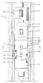
- FIG. 1is a partial section view of a wellbore illustrating the assembly of the present invention in a run-in position.
- FIG. 2is an enlarged sectional view of a wall in the lower string of casing more fully showing one embodiment of a scribe of the present invention.
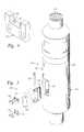
- FIG. 3is an exploded view of an expander tool as might be used in the methods of the present invention.
- FIG. 4is a perspective view showing a shearable connection for an expansion member.
- FIGS. 5A-5Dare section views taken along a line 5 — 5 of FIG. 1 and illustrating the position of expansion members during progressive operation of the expansion tool.
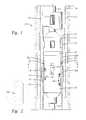
- FIG. 6is a partial section view of the apparatus in a wellbore illustrating a portion of the lower string of casing, including slip and sealing members, having been expanded into the upper string of casing therearound.
- FIG. 7is a partial section view of the apparatus illustrating the lower string of casing expanded into frictional and sealing engagement with the upper string of casing.
- FIG. 7further depicts the lower string of casing having been severed into an upper portion and a lower portion due to expansion.
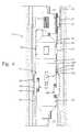
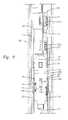
- FIG. 8is a partial section view of the wellbore illustrating a section of the lower casing string expanded into the upper casing string after the expansion tool and run-in string have been removed.
- FIG. 9is a cross-sectional view of an expander tool residing within a wellbore. Above the expander tool is a torque anchor for preventing rotational movement of the lower string of casing during initial expansion thereof. Expansion of the casing has not yet begun.
- FIG. 10is a cross-sectional view of an expander tool of FIG. 9 .
- the torque anchor and expander toolhave been actuated, and expansion of the lower casing string has begun.
- FIG. 1is a section view of a wellbore 100 illustrating an apparatus 105 for use in the methods of the present invention.
- the apparatus 105essentially defines a string of casing 130 , and an expander tool 120 for expanding the string of casing 130 .
- the expander tool 120By actuation of the expander tool 120 against the inner surface of the string of casing 130 , the string of casing 130 is expanded into a second, upper string of casing 110 which has already been set in the wellbore 100 .
- the top portion of the lower string of casing 130 Uis placed in frictional engagement with the bottom portion of the string of casing 110 .
- a scribe 200is placed into the surface of the lower string of casing 130 .
- An enlarged view of the scribe 200 in one embodimentis shown in FIG. 2 .
- the scribe 200creates an area of structural weakness within the lower casing string 130 .
- the lower string of casing 130is expanded at the depth of the scribe 200 , the lower string of casing 130 is severed into upper 130 U and lower 130 L portions. The upper portion 130 U of the lower casing string 130 can then be easily removed from the wellbore 100 .
- the scribemay serve as a release mechanism for the lower casing string 130 .
- the wellbore 100has been lined with the upper string of casing 110 .
- a working string 115is also shown in FIG. 1 .
- Attached to a lower end of the run-in string 115is an expander tool 120 .
- Also attached to the working string 115is the lower string of casing 130 .
- the lower string of casing 130is supported during run-in by a series of dogs 135 disposed radially about the expander tool 120 .
- the dogs 135are landed in a circumferential profile 134 within the upper string of casing 130 .
- a sealing ring 190is disposed on the outer surface of the lower string of casing 130 .
- the sealing ring 190is an elastomeric member circumferentially fitted onto the outer surface of the casing 130 .
- non-elastomeric materialsmay also be used.
- the sealing ring 190is designed to seal an annular area 201 formed between the outer surface of the lower string of casing 130 and the inner surface of the upper string of casing 110 upon expansion of the lower string 130 into the upper string 110 .
- the slip member 195defines a pair of rings having grip surfaces formed thereon for engaging the inner surface of the upper string of casing 110 when the lower string of casing 130 is expanded.
- one slip ring 195is disposed above the sealing ring 190
- one slip ring 195is disposed below the sealing ring 190 .
- the grip surfaceincludes teeth formed on each slip ring 195 .
- the slipscould be of any shape and the grip surfaces could include any number of geometric shapes, including button-like inserts (not shown) made of high carbon material.
- Fluidis circulated from the surface and into the wellbore 100 through the working string 115 .
- a bore 168shown in FIG. 3, runs through the expander tool 120 , placing the working string 115 and the expander tool 120 in fluid communication.
- a fluid outlet 125is provided at the lower end of the expander tool 120 .
- a tubular memberserves as the fluid outlet 125 .
- the fluid outlet 125serves as a fluid conduit for cement to be circulated into the wellbore 100 in accordance with the method of the present invention.
- the expander tool 120includes a swivel 138 .
- the swivel 138allows the expander tool 120 to be rotated by the working tubular 115 while the supporting dogs 135 remain stationary.
- FIG. 3is an exploded view of the expander tool 120 itself.
- the expander tool 120consists of a cylindrical body 150 having a plurality of windows 155 formed therearound. Within each window 155 is an expansion assembly 160 which includes a roller 165 disposed on an axle 170 which is supported at each end by a piston 175 . The piston 175 is retained in the body 150 by a pair of retention members 172 that are held in place by screws 174 .
- the assembly 160includes a piston surface 180 formed opposite the piston 175 which is acted upon by pressurized fluid in the bore 168 of the expander tool 120 . The pressurized fluid causes the expansion assembly 160 to extend radially outward and into contact with the inner surface of the lower string of casing 130 . With a predetermined amount of fluid pressure acting on the piston surface 180 of piston 175 , the lower string of casing 130 is expanded past its elastic limits.
- the expander tool 120 illustrated in FIGS. 1 and 3includes expansion assemblies 160 that are disposed around the perimeter of the expander tool body 150 in a spiraling fashion. Located at an upper position on the expander tool 120 are two opposed expansion assemblies 160 located 180° apart. The expander tool 120 is constructed and arranged whereby the uppermost expansion members 161 are actuated after the other assemblies 160 .
- the uppermost expansion members 161are retained in their retracted position by at least one shear pin 162 which fails with the application of a predetermined radial force.
- the shearable connectionis illustrated as two pin members 162 extending from a retention member 172 to a piston 175 .
- FIGS. 5A-5Dare section views of the expander tool 120 taken along lines 5 — 5 of FIG. 1 .
- the purpose of FIGS. 5A-5Dis to illustrate the relative position of the various expansion assemblies 160 and 161 during operation of the expander tool 120 in a wellbore 100 .
- FIG. 5Aillustrates the expander tool 120 in the run-in position with all of the radially outward extending expansion assemblies 160 , 161 in a retracted position within the body 150 of the expander tool 120 . In this position, the expander tool 120 can be run into a wellbore 100 without creating a profile any larger than the outside diameter of the expansion tool body 150 .
- FIG. 5Billustrates the expander tool 120 with all but the upper-most expansion assemblies 160 and 161 actuated.
- the expander tool 120would have expanded a portion of the lower string of casing 130 axially as well as radially.
- the expander tool 120 and working string 115can be rotated relative to the lower string of casing 130 to form a circumferential area of expanded liner 130 L. Rotation is possible due to a swivel 138 located above the expander tool 120 which permits rotation of the expander tool 120 while ensuring the weight of the casing 130 is borne by the dogs 135 .
- FIG. 6presents a partial section view of the apparatus 105 after expanding a portion of the lower string of casing 130 L into the upper string of casing 110 .
- Expansion assemblies 160have been actuated in order to act against the inner surface of the lower string of casing 130 L.
- FIG. 6corresponds to FIG. 5 B.
- sealing ring 190in contact with the inside wall of the casing 110 .
- Slips 195are also in contact with the upper string of casing 110 .
- FIG. 5Cis a top section view of a top expansion member 160 in its recessed state. Present in this view is a piston 175 residing within the body 150 of the expander tool 120 . Also present is the shearable connection, i.e., shear pins 162 of FIG. 4 .
- this figureillustrates the expander tool 120 with all of the expansion assemblies 160 and 161 actuated, including the uppermost expansion members 161 .
- the uppermost expansion members 161are constructed and arranged to become actuated only after the lower assemblies 160 have been actuated.
- FIG. 7depicts a wellbore 100 having an expander tool 120 and lower string of casing 130 of the present invention disposed therein.
- all of the expansion assemblies 160 , 161including the uppermost expansion members 161 , have been actuated.
- FIG. 7corresponds to the step presented in FIG. 5 D.
- a scribe 200formed on the surface of the lower string of casing 130 L adjacent the uppermost expansion member 161 is a scribe 200 .
- the scribe 200creates an area of structural weakness within the lower casing string 130 .
- the lower string of casing 130breaks cleanly into upper 130 U and lower 130 L portions.
- the upper portion 130 U of the lower casing string 130can then be easily removed from the wellbore 100 .
- the inventorshave determined that a scribe 200 in the wall of a string of casing 130 or other tubular will allow the casing 130 to break cleanly when radial outward pressure is placed at the point of the scribe 200 .
- the depth of the cut 200 needed to cause the breakis dependent upon a variety of factors, including the tensile strength of the tubular, the overall deflection of the material as it is expanded, the profile of the cut, and the weight of the tubular being hung.
- the scope of the present inventionis not limited by the depth of the particular cut or cuts 200 being applied, so long as the scribe 200 is shallow enough that the tensile strength of the tubular 130 supports the weight below the scribe 200 during run-in.
- the preferred embodiment, shown in FIG. 2,employs a single scribe 200 having a V-shaped profile so as to impart a high stress concentration onto the casing wall.
- the scribe 200is formed on the outer surface of the lower string of casing 130 . Further, the scribe 200 is preferably placed around the casing 130 circumferentially. Because the lower string of casing 130 and the expander tool 120 are run into the wellbore 100 together, and because no axial movement of the expander tool 120 in relation to the casing 130 is necessary, the position of the upper expansion members 161 with respect to the scribe 200 can be predetermined and set at the surface of the well or during assembly of the apparatus 105 .
- FIG. 7again, shows the expander tool 120 with all of the expansion assemblies 160 and 161 actuated, including the uppermost expansion members 161 .
- the scribe 200has caused a clean horizontal break around a perimeter of the lower string of casing 130 such that a lower portion of the casing 130 L has separated from an upper portion 130 U thereof.
- the swivel 138permitted the run-in string 115 and expansion tool 120 to be rotated within the wellbore 100 independent of the casing 130 , ensuring that the casing 130 is expanded in a circumferential manner.
- the apparatus 105enables a lower string of casing 130 to be hung onto an upper string of casing 110 by expanding the lower string 130 into the upper string 110 .
- FIG. 8illustrates the lower string of casing 130 set in the wellbore 100 with the run-in string 115 and expander tool 120 removed.
- expansion of the lower string of casing 130has occurred.
- the slip rings 195 and the seal ring 190are engaged to the inner surface of the upper string of casing 110 .
- the annulus 201 between the lower string of casing 130 and the upper string of casinghas been filled with cement, excepting that portion of the annulus which has been removed by expansion of the lower string of casing 130 .
- the method and apparatus of the present inventioncan be utilized as follows: a wellbore 100 having a cemented casing 110 therein is drilled to a new depth. Thereafter, the drill string and drill bit are removed and the apparatus 105 is run into the wellbore 100 .
- the apparatus 105includes a new string of inscribed casing 130 supported by an expander tool 120 and a run-in string 115 . As the apparatus 105 reaches a predetermined depth in the wellbore 100 , the casing 130 can be cemented in place by injecting cement through the run-in string 115 , the expander tool 120 and the tubular member 125 . Cement is then circulated into the annulus 201 between the two strings of casing 110 and 130 .
- the expander tool 120With the cement injected into the annulus 201 between the two strings of casing 110 and 130 , but prior to curing of the cement, the expander tool 120 is actuated with fluid pressure delivered from the run-in string 115 .
- the expansion assemblies 160 (other than the upper-most expansion members 161 ) of the expander tool 120extend radially outward into contact with the lower string of casing 130 to plastically deform the lower string of casing 130 into frictional contact with the upper string of casing 110 therearound.
- the expander tool 120is then rotated in the wellbore 100 independent of the casing 130 . In this manner, a portion of the lower string of casing 130 L below the scribe 200 is expanded circumferentially into contact with the upper string of casing 110 .
- the uppermost expansion members 161are actuated. Additional fluid pressure from the surface applied into the bore 168 of the expander tool 120 will cause a temporary connection 162 holding the upper expansion members 161 within the body 150 of the expander tool 120 to fail. This, in turn, will cause the pistons 175 of the upper expansion members 161 to move from a first recessed position within the body 150 of the expander tool 120 to a second extended position. Rollers 165 of the uppermost expansion members 161 then act against the inner surface of the lower string of casing 130 L at the depth of the scribe 200 , causing an additional portion of the lower string of casing 130 to be expanded against the upper string of casing 110 .
- a scribe 200 formed on the outer surface of the lower string of casing 130causes the casing 130 to break into upper 130 U and lower 130 L portions. Because the lower portion of the casing 130 L has been completely expanded into contact with the upper string of casing 110 , the lower portion of the lower string of casing 130 L is successfully hung in the wellbore 100 .
- the apparatus 105including the expander tool 120 , the working string 115 and the upper portion of the top end of the lower string of casing 130 U can then be removed, leaving a sealed overlap between the lower string of casing 130 and the upper string of casing 110 , as illustrated in FIG. 8 .
- FIGS. 5A-5Ddepict a series of expansions in sequential stages.
- the above discussionoutlines one embodiment of the method of the present invention for expanding and separating tubulars in a wellbore through sequential stages.
- the method of the present inventionencompasses the expansion of rollers 165 at all rows at the same time.
- the present inventionencompasses the use of a rotary expander tool 120 of any configuration, including one in which only one row of roller assemblies 160 is utilized. With this arrangement, the rollers 165 would need to be positioned at the depth of the scribe 200 for expansion. Alternatively, the additional step of raising the expander tool 120 across the depth of the scribe 200 would be taken. Vertically translating the expander tool 120 could be accomplished by raising the working string 115 or by utilizing an actuation apparatus downhole (not shown) which would translate the expander tool 120 without raising the drill string 115 .
- a swaged cone(not shown) in order to expand a tubular in accordance with the present invention.
- a swaged conical expander toolexpands by being pushed or otherwise translated through a section of tubular to be expanded.
- the present inventionis not limited by the type of expander tool employed.
- a torque anchormay optionally be utilized.
- the torque anchorserves to prevent rotation of the lower string of casing 130 during the expansion process.
- Those of ordinary skill in the artmay perceive that the radially outward force applied by the rollers 165 , when combined with rotation of the expander tool 120 could cause some rotation of the casing 130 .
- the torque anchor 140defines a set of slip members 141 disposed radially around the lower string of casing 130 .
- the slip members 141define at least two radially extendable pads with surfaces having gripping formations like teeth formed thereon to prevent rotational movement.
- the anchor 140is in its recessed position, meaning that the pads 141 are substantially within the plane of the lower casing string 130 .
- the pads 141are not in contact with the upper casing string 110 so as to facilitate the run-in of the apparatus 105 .
- the pads 141are selectively actuated either hydraulically or mechanically or both as is known in the art.
- the anchor 140is in its extended position. This means that the pads 141 have been actuated to engage the inner surface of the upper string of casing 110 . This position allows the lower string of casing 130 to be fixed in place while the lower string of casing 130 is expanded into the wellbore 100 .
- FIG. 9An alternative embodiment for a torque anchor 250 is presented in FIG. 9 .
- the torque anchor 250defines a body having sets of wheels 254 U and 254 L radially disposed around its perimeter.
- the wheels 254 U and 254 Lreside within wheel housings 253 , and are oriented to permit axial (vertical) movement, but not radial movement, of the torque anchor 250 .
- Sharp edges (not shown) along the wheels 254 U and 254 Laid in inhibiting radial movement of the torque anchor 250 .
- four sets of wheels 254 U and 254 Lare employed to act against the upper casing 110 and the lower casing 130 , respectively.
- the torque anchor 250is run into the wellbore 100 on the working string 115 along with the expander tool 120 and the lower casing string 130 .
- the run-in position of the torque anchor 250is shown in FIG. 9 .
- the wheel housings 253are maintained essentially within the torque anchor body 250 .
- the torque anchor 250is activated. Fluid pressure provided from the surface through the working tubular 115 acts against the wheel housings 253 to force the wheels 254 C and 254 L outward from the torque anchor body 250 .
- Wheels 254 Cact against the inner surface of the upper casing string 130
- wheels 254 Lact against the inner surface of the lower casing string 130 .
- This activated positionis depicted in FIG. 10 .
- a rotating sleeve 251resides longitudinally within the torque anchor 250 .
- the sleeve 251rotates independent of the torque anchor body 250 . Rotation is imparted by the working tubular 115 . In turn, the sleeve provides the rotational force to rotate the expander 120 .
- the expander tool 120is deactivated. In this regard, fluid pressure supplied to the pistons 175 is reduced or released, allowing the pistons 175 to return to the recesses 155 within the central body 150 of the tool 120 .
- the expander tool 120can then be withdrawn from the wellbore 100 by pulling the run-in tubular 115 .
Landscapes
- Geology (AREA)
- Life Sciences & Earth Sciences (AREA)
- Engineering & Computer Science (AREA)
- Mining & Mineral Resources (AREA)
- Environmental & Geological Engineering (AREA)
- Fluid Mechanics (AREA)
- Physics & Mathematics (AREA)
- General Life Sciences & Earth Sciences (AREA)
- Geochemistry & Mineralogy (AREA)
- Processing Of Stones Or Stones Resemblance Materials (AREA)
- Earth Drilling (AREA)
- Wire Processing (AREA)
- Underground Or Underwater Handling Of Building Materials (AREA)
Abstract
Description
Claims (28)
Priority Applications (8)
| Application Number | Priority Date | Filing Date | Title |
|---|---|---|---|
| US09/969,089US6752215B2 (en) | 1999-12-22 | 2001-10-02 | Method and apparatus for expanding and separating tubulars in a wellbore |
| GB0406969AGB2397601B (en) | 2001-10-02 | 2002-09-26 | Method and apparatus for expanding and separating tubulars in a wellbore |
| GB0519435AGB2415453B (en) | 2001-10-02 | 2002-09-26 | An expander tool and a method for expanding a wellbore tubular |
| PCT/GB2002/004368WO2003029608A1 (en) | 2001-10-02 | 2002-09-26 | Method and apparatus for expanding and separating tubulars in a wellbore |
| CA2683103ACA2683103C (en) | 1999-12-22 | 2002-09-26 | Method and apparatus for expanding and separating tubulars in a wellbore |
| CA002462115ACA2462115C (en) | 2001-10-02 | 2002-09-26 | Method and apparatus for expanding and separating tubulars in a wellbore |
| US10/863,825US7373990B2 (en) | 1999-12-22 | 2004-06-08 | Method and apparatus for expanding and separating tubulars in a wellbore |
| US12/119,216US7921925B2 (en) | 1999-12-22 | 2008-05-12 | Method and apparatus for expanding and separating tubulars in a wellbore |
Applications Claiming Priority (2)
| Application Number | Priority Date | Filing Date | Title |
|---|---|---|---|
| US09/469,690US6457532B1 (en) | 1998-12-22 | 1999-12-22 | Procedures and equipment for profiling and jointing of pipes |
| US09/969,089US6752215B2 (en) | 1999-12-22 | 2001-10-02 | Method and apparatus for expanding and separating tubulars in a wellbore |
Related Parent Applications (1)
| Application Number | Title | Priority Date | Filing Date |
|---|---|---|---|
| US09/469,690Continuation-In-PartUS6457532B1 (en) | 1998-12-22 | 1999-12-22 | Procedures and equipment for profiling and jointing of pipes |
Related Child Applications (1)
| Application Number | Title | Priority Date | Filing Date |
|---|---|---|---|
| US10/863,825Continuation-In-PartUS7373990B2 (en) | 1999-12-22 | 2004-06-08 | Method and apparatus for expanding and separating tubulars in a wellbore |
Publications (2)
| Publication Number | Publication Date |
|---|---|
| US20030062171A1 US20030062171A1 (en) | 2003-04-03 |
| US6752215B2true US6752215B2 (en) | 2004-06-22 |
Family
ID=25515162
Family Applications (1)
| Application Number | Title | Priority Date | Filing Date |
|---|---|---|---|
| US09/969,089Expired - LifetimeUS6752215B2 (en) | 1999-12-22 | 2001-10-02 | Method and apparatus for expanding and separating tubulars in a wellbore |
Country Status (4)
| Country | Link |
|---|---|
| US (1) | US6752215B2 (en) |
| CA (1) | CA2462115C (en) |
| GB (1) | GB2397601B (en) |
| WO (1) | WO2003029608A1 (en) |
Cited By (10)
| Publication number | Priority date | Publication date | Assignee | Title |
|---|---|---|---|---|
| US20030127774A1 (en)* | 2001-11-30 | 2003-07-10 | Weatherford/Lamb, Inc. | Tubing expansion |
| US20030146003A1 (en)* | 2001-12-27 | 2003-08-07 | Duggan Andrew Michael | Bore isolation |
| US20050011650A1 (en)* | 1999-12-22 | 2005-01-20 | Weatherford/Lamb Inc. | Method and apparatus for expanding and separating tubulars in a wellbore |
| US20050016738A1 (en)* | 2003-07-09 | 2005-01-27 | Metcalfe Paul David | Expansion apparatus |
| US20050121202A1 (en)* | 2003-06-13 | 2005-06-09 | Abercrombie Simpson Neil A. | Method and apparatus for supporting a tubular in a bore |
| US20070000664A1 (en)* | 2005-06-30 | 2007-01-04 | Weatherford/Lamb, Inc. | Axial compression enhanced tubular expansion |
| US20070187113A1 (en)* | 2006-02-15 | 2007-08-16 | Weatherford/Lamb, Inc. | Method and apparatus for expanding tubulars in a wellbore |
| US7350584B2 (en) | 2002-07-06 | 2008-04-01 | Weatherford/Lamb, Inc. | Formed tubulars |
| US20100319929A1 (en)* | 2009-06-18 | 2010-12-23 | Victor Matthew Bolze | Dual Anchoring Tubular Back-Off Tool |
| US8069916B2 (en) | 2007-01-03 | 2011-12-06 | Weatherford/Lamb, Inc. | System and methods for tubular expansion |
Families Citing this family (74)
| Publication number | Priority date | Publication date | Assignee | Title |
|---|---|---|---|---|
| US6823937B1 (en) | 1998-12-07 | 2004-11-30 | Shell Oil Company | Wellhead |
| US7231985B2 (en) | 1998-11-16 | 2007-06-19 | Shell Oil Company | Radial expansion of tubular members |
| US7357188B1 (en) | 1998-12-07 | 2008-04-15 | Shell Oil Company | Mono-diameter wellbore casing |
| AU2001269810B2 (en) | 1998-11-16 | 2005-04-07 | Shell Oil Company | Radial expansion of tubular members |
| US6557640B1 (en) | 1998-12-07 | 2003-05-06 | Shell Oil Company | Lubrication and self-cleaning system for expansion mandrel |
| US6745845B2 (en) | 1998-11-16 | 2004-06-08 | Shell Oil Company | Isolation of subterranean zones |
| US7603758B2 (en) | 1998-12-07 | 2009-10-20 | Shell Oil Company | Method of coupling a tubular member |
| US7195064B2 (en) | 1998-12-07 | 2007-03-27 | Enventure Global Technology | Mono-diameter wellbore casing |
| GB2344606B (en) | 1998-12-07 | 2003-08-13 | Shell Int Research | Forming a wellbore casing by expansion of a tubular member |
| US7552776B2 (en) | 1998-12-07 | 2009-06-30 | Enventure Global Technology, Llc | Anchor hangers |
| US7363984B2 (en) | 1998-12-07 | 2008-04-29 | Enventure Global Technology, Llc | System for radially expanding a tubular member |
| US7185710B2 (en) | 1998-12-07 | 2007-03-06 | Enventure Global Technology | Mono-diameter wellbore casing |
| US6758278B2 (en) | 1998-12-07 | 2004-07-06 | Shell Oil Company | Forming a wellbore casing while simultaneously drilling a wellbore |
| GB2356651B (en) | 1998-12-07 | 2004-02-25 | Shell Int Research | Lubrication and self-cleaning system for expansion mandrel |
| AU770359B2 (en) | 1999-02-26 | 2004-02-19 | Shell Internationale Research Maatschappij B.V. | Liner hanger |
| US7055608B2 (en) | 1999-03-11 | 2006-06-06 | Shell Oil Company | Forming a wellbore casing while simultaneously drilling a wellbore |
| CA2306656C (en) | 1999-04-26 | 2006-06-06 | Shell Internationale Research Maatschappij B.V. | Expandable connector for borehole tubes |
| US7350563B2 (en) | 1999-07-09 | 2008-04-01 | Enventure Global Technology, L.L.C. | System for lining a wellbore casing |
| AU783245B2 (en) | 1999-11-01 | 2005-10-06 | Shell Internationale Research Maatschappij B.V. | Wellbore casing repair |
| US7234531B2 (en) | 1999-12-03 | 2007-06-26 | Enventure Global Technology, Llc | Mono-diameter wellbore casing |
| US7100684B2 (en) | 2000-07-28 | 2006-09-05 | Enventure Global Technology | Liner hanger with standoffs |
| CA2416573A1 (en) | 2000-09-18 | 2002-03-21 | Shell Canada Ltd | Liner hanger with sliding sleeve valve |
| US7100685B2 (en) | 2000-10-02 | 2006-09-05 | Enventure Global Technology | Mono-diameter wellbore casing |
| AU2001294802B2 (en) | 2000-10-02 | 2005-12-01 | Shell Internationale Research Maatschappij B.V. | Method and apparatus for casing expansion |
| CA2428819A1 (en) | 2001-01-03 | 2002-07-11 | Enventure Global Technology | Mono-diameter wellbore casing |
| US7410000B2 (en) | 2001-01-17 | 2008-08-12 | Enventure Global Technology, Llc. | Mono-diameter wellbore casing |
| US7172027B2 (en)* | 2001-05-15 | 2007-02-06 | Weatherford/Lamb, Inc. | Expanding tubing |
| WO2003004820A2 (en) | 2001-07-06 | 2003-01-16 | Enventure Global Technology | Liner hanger |
| GB0117178D0 (en)* | 2001-07-13 | 2001-09-05 | B D Kendle Engineering Ltd | Improvements to roller subs |
| US7258168B2 (en) | 2001-07-27 | 2007-08-21 | Enventure Global Technology L.L.C. | Liner hanger with slip joint sealing members and method of use |
| GB2396639B (en) | 2001-08-20 | 2006-03-08 | Enventure Global Technology | An apparatus for forming a wellbore casing by use of an adjustable tubular expansion cone |
| CA2459910C (en) | 2001-09-07 | 2010-04-13 | Enventure Global Technology | Adjustable expansion cone assembly |
| WO2004081346A2 (en) | 2003-03-11 | 2004-09-23 | Enventure Global Technology | Apparatus for radially expanding and plastically deforming a tubular member |
| US7546881B2 (en) | 2001-09-07 | 2009-06-16 | Enventure Global Technology, Llc | Apparatus for radially expanding and plastically deforming a tubular member |
| US7513313B2 (en) | 2002-09-20 | 2009-04-07 | Enventure Global Technology, Llc | Bottom plug for forming a mono diameter wellbore casing |
| WO2004094766A2 (en) | 2003-04-17 | 2004-11-04 | Enventure Global Technology | Apparatus for radially expanding and plastically deforming a tubular member |
| AU2002343651A1 (en)* | 2001-11-12 | 2003-05-26 | Enventure Global Technology | Collapsible expansion cone |
| US7661470B2 (en)* | 2001-12-20 | 2010-02-16 | Baker Hughes Incorporated | Expandable packer with anchoring feature |
| US7051805B2 (en)* | 2001-12-20 | 2006-05-30 | Baker Hughes Incorporated | Expandable packer with anchoring feature |
| US7290605B2 (en) | 2001-12-27 | 2007-11-06 | Enventure Global Technology | Seal receptacle using expandable liner hanger |
| WO2003089161A2 (en) | 2002-04-15 | 2003-10-30 | Enventure Global Technlogy | Protective sleeve for threaded connections for expandable liner hanger |
| WO2004018823A2 (en) | 2002-08-23 | 2004-03-04 | Enventure Global Technology | Interposed joint sealing layer method of forming a wellbore casing |
| WO2004027786A2 (en) | 2002-09-20 | 2004-04-01 | Enventure Global Technology | Protective sleeve for expandable tubulars |
| WO2003086675A2 (en) | 2002-04-12 | 2003-10-23 | Enventure Global Technology | Protective sleeve for threaded connections for expandable liner hanger |
| WO2004018824A2 (en) | 2002-08-23 | 2004-03-04 | Enventure Global Technology | Magnetic impulse applied sleeve method of forming a wellbore casing |
| MXPA04007922A (en) | 2002-02-15 | 2005-05-17 | Enventure Global Technology | Mono-diameter wellbore casing. |
| US7360591B2 (en) | 2002-05-29 | 2008-04-22 | Enventure Global Technology, Llc | System for radially expanding a tubular member |
| GB2418943B (en) | 2002-06-10 | 2006-09-06 | Enventure Global Technology | Mono Diameter Wellbore Casing |
| GB2410280B (en) | 2002-09-20 | 2007-04-04 | Enventure Global Technology | Self-lubricating expansion mandrel for expandable tubular |
| AU2003265452A1 (en) | 2002-09-20 | 2004-04-08 | Enventure Global Technology | Pipe formability evaluation for expandable tubulars |
| US7886831B2 (en) | 2003-01-22 | 2011-02-15 | Enventure Global Technology, L.L.C. | Apparatus for radially expanding and plastically deforming a tubular member |
| WO2004067961A2 (en) | 2003-01-27 | 2004-08-12 | Enventure Global Technology | Lubrication system for radially expanding tubular members |
| GB2429996B (en) | 2003-02-26 | 2007-08-29 | Enventure Global Technology | Apparatus for radially expanding and plastically deforming a tubular member |
| US7028780B2 (en)* | 2003-05-01 | 2006-04-18 | Weatherford/Lamb, Inc. | Expandable hanger with compliant slip system |
| US7093656B2 (en)* | 2003-05-01 | 2006-08-22 | Weatherford/Lamb, Inc. | Solid expandable hanger with compliant slip system |
| US7441606B2 (en)* | 2003-05-01 | 2008-10-28 | Weatherford/Lamb, Inc. | Expandable fluted liner hanger and packer system |
| US20050166387A1 (en) | 2003-06-13 | 2005-08-04 | Cook Robert L. | Method and apparatus for forming a mono-diameter wellbore casing |
| US7712522B2 (en) | 2003-09-05 | 2010-05-11 | Enventure Global Technology, Llc | Expansion cone and system |
| US7225880B2 (en) | 2004-05-27 | 2007-06-05 | Tiw Corporation | Expandable liner hanger system and method |
| GB2432866A (en) | 2004-08-13 | 2007-06-06 | Enventure Global Technology | Expandable tubular |
| GB2440879B (en)* | 2005-05-26 | 2010-09-22 | Tiw Corp | Expandable liner hanger system and method |
| US20140174759A1 (en)* | 2012-12-20 | 2014-06-26 | Schlumberger Technology Corporation | Downhole Tool Centralizing Pistons |
| US10408012B2 (en) | 2015-07-24 | 2019-09-10 | Innovex Downhole Solutions, Inc. | Downhole tool with an expandable sleeve |
| US9976381B2 (en) | 2015-07-24 | 2018-05-22 | Team Oil Tools, Lp | Downhole tool with an expandable sleeve |
| US10156119B2 (en) | 2015-07-24 | 2018-12-18 | Innovex Downhole Solutions, Inc. | Downhole tool with an expandable sleeve |
| US10337298B2 (en) | 2016-10-05 | 2019-07-02 | Tiw Corporation | Expandable liner hanger system and method |
| US10227842B2 (en) | 2016-12-14 | 2019-03-12 | Innovex Downhole Solutions, Inc. | Friction-lock frac plug |
| US10989016B2 (en) | 2018-08-30 | 2021-04-27 | Innovex Downhole Solutions, Inc. | Downhole tool with an expandable sleeve, grit material, and button inserts |
| US11125039B2 (en) | 2018-11-09 | 2021-09-21 | Innovex Downhole Solutions, Inc. | Deformable downhole tool with dissolvable element and brittle protective layer |
| US11965391B2 (en) | 2018-11-30 | 2024-04-23 | Innovex Downhole Solutions, Inc. | Downhole tool with sealing ring |
| US11396787B2 (en) | 2019-02-11 | 2022-07-26 | Innovex Downhole Solutions, Inc. | Downhole tool with ball-in-place setting assembly and asymmetric sleeve |
| US11261683B2 (en) | 2019-03-01 | 2022-03-01 | Innovex Downhole Solutions, Inc. | Downhole tool with sleeve and slip |
| US11203913B2 (en) | 2019-03-15 | 2021-12-21 | Innovex Downhole Solutions, Inc. | Downhole tool and methods |
| US11572753B2 (en) | 2020-02-18 | 2023-02-07 | Innovex Downhole Solutions, Inc. | Downhole tool with an acid pill |
Citations (66)
| Publication number | Priority date | Publication date | Assignee | Title |
|---|---|---|---|---|
| US761518A (en) | 1903-08-19 | 1904-05-31 | Henry G Lykken | Tube expanding, beading, and cutting tool. |
| US1324303A (en) | 1919-12-09 | Mfe-cutteb | ||
| US1545039A (en) | 1923-11-13 | 1925-07-07 | Henry E Deavers | Well-casing straightening tool |
| US1561418A (en) | 1924-01-26 | 1925-11-10 | Reed Roller Bit Co | Tool for straightening tubes |
| US1569729A (en) | 1923-12-27 | 1926-01-12 | Reed Roller Bit Co | Tool for straightening well casings |
| US1597212A (en) | 1924-10-13 | 1926-08-24 | Arthur F Spengler | Casing roller |
| US1930825A (en) | 1932-04-28 | 1933-10-17 | Edward F Raymond | Combination swedge |
| US1981525A (en) | 1933-12-05 | 1934-11-20 | Bailey E Price | Method of and apparatus for drilling oil wells |
| US2175372A (en)* | 1937-02-04 | 1939-10-10 | James S Abercrombie | Inside pipe cutter |
| US2214226A (en) | 1939-03-29 | 1940-09-10 | English Aaron | Method and apparatus useful in drilling and producing wells |
| US2216226A (en) | 1937-08-19 | 1940-10-01 | Gen Shoe Corp | Shoe |
| US2383214A (en) | 1943-05-18 | 1945-08-21 | Bessie Pugsley | Well casing expander |
| US2499630A (en) | 1946-12-05 | 1950-03-07 | Paul B Clark | Casing expander |
| US2627891A (en) | 1950-11-28 | 1953-02-10 | Paul B Clark | Well pipe expander |
| US2663073A (en) | 1952-03-19 | 1953-12-22 | Acrometal Products Inc | Method of forming spools |
| US2898971A (en) | 1955-05-11 | 1959-08-11 | Mcdowell Mfg Co | Roller expanding and peening tool |
| US3087546A (en) | 1958-08-11 | 1963-04-30 | Brown J Woolley | Methods and apparatus for removing defective casing or pipe from well bores |
| US3191677A (en) | 1963-04-29 | 1965-06-29 | Myron M Kinley | Method and apparatus for setting liners in tubing |
| US3191680A (en) | 1962-03-14 | 1965-06-29 | Pan American Petroleum Corp | Method of setting metallic liners in wells |
| US3195646A (en) | 1963-06-03 | 1965-07-20 | Brown Oil Tools | Multiple cone liner hanger |
| US3467180A (en) | 1965-04-14 | 1969-09-16 | Franco Pensotti | Method of making a composite heat-exchanger tube |
| US3712376A (en) | 1971-07-26 | 1973-01-23 | Gearhart Owen Industries | Conduit liner for wellbore and method and apparatus for setting same |
| US3776307A (en) | 1972-08-24 | 1973-12-04 | Gearhart Owen Industries | Apparatus for setting a large bore packer in a well |
| US3818734A (en) | 1973-05-23 | 1974-06-25 | J Bateman | Casing expanding mandrel |
| US3911707A (en) | 1974-10-08 | 1975-10-14 | Anatoly Petrovich Minakov | Finishing tool |
| US3948321A (en) | 1974-08-29 | 1976-04-06 | Gearhart-Owen Industries, Inc. | Liner and reinforcing swage for conduit in a wellbore and method and apparatus for setting same |
| GB1448304A (en) | 1973-06-25 | 1976-09-02 | Petroles Cie Francaise | Bore hole drilling |
| US4069573A (en) | 1976-03-26 | 1978-01-24 | Combustion Engineering, Inc. | Method of securing a sleeve within a tube |
| US4127168A (en) | 1977-03-11 | 1978-11-28 | Exxon Production Research Company | Well packers using metal to metal seals |
| US4159564A (en) | 1978-04-14 | 1979-07-03 | Westinghouse Electric Corp. | Mandrel for hydraulically expanding a tube into engagement with a tubesheet |
| US4288082A (en) | 1980-04-30 | 1981-09-08 | Otis Engineering Corporation | Well sealing system |
| US4319393A (en) | 1978-02-17 | 1982-03-16 | Texaco Inc. | Methods of forming swages for joining two small tubes |
| US4324407A (en) | 1980-10-06 | 1982-04-13 | Aeroquip Corporation | Pressure actuated metal-to-metal seal |
| US4429620A (en) | 1979-02-22 | 1984-02-07 | Exxon Production Research Co. | Hydraulically operated actuator |
| US4483399A (en) | 1981-02-12 | 1984-11-20 | Colgate Stirling A | Method of deep drilling |
| US4509777A (en) | 1982-11-01 | 1985-04-09 | Dril-Quip Inc. | Weld-on casing connector |
| US4531581A (en) | 1984-03-08 | 1985-07-30 | Camco, Incorporated | Piston actuated high temperature well packer |
| US4538442A (en) | 1982-08-31 | 1985-09-03 | The Babcock & Wilcox Company | Method of prestressing a tubular apparatus |
| US4588030A (en) | 1984-09-27 | 1986-05-13 | Camco, Incorporated | Well tool having a metal seal and bi-directional lock |
| US4697640A (en) | 1986-01-16 | 1987-10-06 | Halliburton Company | Apparatus for setting a high temperature packer |
| US4723905A (en) | 1985-03-18 | 1988-02-09 | Vassallo Research And Development Corporation | Pipe belling apparatus |
| US4848469A (en) | 1988-06-15 | 1989-07-18 | Baker Hughes Incorporated | Liner setting tool and method |
| GB2216926A (en) | 1988-04-06 | 1989-10-18 | Jumblefierce Limited | Drilling and lining a borehole |
| US5052483A (en) | 1990-11-05 | 1991-10-01 | Bestline Liner Systems | Sand control adapter |
| WO1993024728A1 (en) | 1992-05-27 | 1993-12-09 | Astec Developments Limited | Downhole tools |
| US5271472A (en) | 1991-08-14 | 1993-12-21 | Atlantic Richfield Company | Drilling with casing and retrievable drill bit |
| US5348095A (en) | 1992-06-09 | 1994-09-20 | Shell Oil Company | Method of creating a wellbore in an underground formation |
| US5409059A (en) | 1991-08-28 | 1995-04-25 | Petroline Wireline Services Limited | Lock mandrel for downhole assemblies |
| US5435400A (en) | 1994-05-25 | 1995-07-25 | Atlantic Richfield Company | Lateral well drilling |
| US5472057A (en) | 1994-04-11 | 1995-12-05 | Atlantic Richfield Company | Drilling with casing and retrievable bit-motor assembly |
| US5560426A (en) | 1995-03-27 | 1996-10-01 | Baker Hughes Incorporated | Downhole tool actuating mechanism |
| US5685369A (en) | 1996-05-01 | 1997-11-11 | Abb Vetco Gray Inc. | Metal seal well packer |
| GB2320734A (en) | 1996-12-14 | 1998-07-01 | Baker Hughes Inc | Casing Packer |
| GB2329918A (en) | 1997-10-03 | 1999-04-07 | Baker Hughes Inc | Downhole pipe expansion apparatus and method |
| WO1999018328A1 (en) | 1997-10-08 | 1999-04-15 | Formlock, Inc. | Method and apparatus for hanging tubulars in wells |
| US5901787A (en) | 1995-06-09 | 1999-05-11 | Tuboscope (Uk) Ltd. | Metal sealing wireline plug |
| WO1999023354A1 (en) | 1997-11-01 | 1999-05-14 | Weatherford/Lamb, Inc. | Expandable downhole tubing |
| EP0961007A2 (en) | 1998-05-28 | 1999-12-01 | Halliburton Energy Services, Inc. | Expandable wellbore junction |
| US6000482A (en) | 1997-06-04 | 1999-12-14 | Michalski; Joseph W. | Drilling pipe for directional boring |
| US6012523A (en) | 1995-11-24 | 2000-01-11 | Petroline Wellsystems Limited | Downhole apparatus and method for expanding a tubing |
| US6029748A (en) | 1997-10-03 | 2000-02-29 | Baker Hughes Incorporated | Method and apparatus for top to bottom expansion of tubulars |
| US6053247A (en) | 1997-10-21 | 2000-04-25 | Marathon Oil Company | Method and apparatus for severing a tubular |
| WO2000037772A1 (en) | 1998-12-22 | 2000-06-29 | Weatherford/Lamb, Inc. | Tubing anchor |
| GB2345308A (en) | 1998-12-22 | 2000-07-05 | Petroline Wellsystems Ltd | Tubing hanger |
| US20010045284A1 (en) | 1999-12-22 | 2001-11-29 | Weatherford/Lamb, Inc. | Apparatus and methods for expanding tubulars in a wellbore |
| US6446724B2 (en) | 1999-05-20 | 2002-09-10 | Baker Hughes Incorporated | Hanging liners by pipe expansion |
- 2001
- 2001-10-02USUS09/969,089patent/US6752215B2/ennot_activeExpired - Lifetime
- 2002
- 2002-09-26GBGB0406969Apatent/GB2397601B/ennot_activeExpired - Fee Related
- 2002-09-26WOPCT/GB2002/004368patent/WO2003029608A1/ennot_activeApplication Discontinuation
- 2002-09-26CACA002462115Apatent/CA2462115C/ennot_activeExpired - Fee Related
Patent Citations (71)
| Publication number | Priority date | Publication date | Assignee | Title |
|---|---|---|---|---|
| US1324303A (en) | 1919-12-09 | Mfe-cutteb | ||
| US761518A (en) | 1903-08-19 | 1904-05-31 | Henry G Lykken | Tube expanding, beading, and cutting tool. |
| US1545039A (en) | 1923-11-13 | 1925-07-07 | Henry E Deavers | Well-casing straightening tool |
| US1569729A (en) | 1923-12-27 | 1926-01-12 | Reed Roller Bit Co | Tool for straightening well casings |
| US1561418A (en) | 1924-01-26 | 1925-11-10 | Reed Roller Bit Co | Tool for straightening tubes |
| US1597212A (en) | 1924-10-13 | 1926-08-24 | Arthur F Spengler | Casing roller |
| US1930825A (en) | 1932-04-28 | 1933-10-17 | Edward F Raymond | Combination swedge |
| US1981525A (en) | 1933-12-05 | 1934-11-20 | Bailey E Price | Method of and apparatus for drilling oil wells |
| US2175372A (en)* | 1937-02-04 | 1939-10-10 | James S Abercrombie | Inside pipe cutter |
| US2216226A (en) | 1937-08-19 | 1940-10-01 | Gen Shoe Corp | Shoe |
| US2214226A (en) | 1939-03-29 | 1940-09-10 | English Aaron | Method and apparatus useful in drilling and producing wells |
| US2383214A (en) | 1943-05-18 | 1945-08-21 | Bessie Pugsley | Well casing expander |
| US2499630A (en) | 1946-12-05 | 1950-03-07 | Paul B Clark | Casing expander |
| US2627891A (en) | 1950-11-28 | 1953-02-10 | Paul B Clark | Well pipe expander |
| US2663073A (en) | 1952-03-19 | 1953-12-22 | Acrometal Products Inc | Method of forming spools |
| US2898971A (en) | 1955-05-11 | 1959-08-11 | Mcdowell Mfg Co | Roller expanding and peening tool |
| US3087546A (en) | 1958-08-11 | 1963-04-30 | Brown J Woolley | Methods and apparatus for removing defective casing or pipe from well bores |
| US3191680A (en) | 1962-03-14 | 1965-06-29 | Pan American Petroleum Corp | Method of setting metallic liners in wells |
| US3191677A (en) | 1963-04-29 | 1965-06-29 | Myron M Kinley | Method and apparatus for setting liners in tubing |
| US3195646A (en) | 1963-06-03 | 1965-07-20 | Brown Oil Tools | Multiple cone liner hanger |
| US3467180A (en) | 1965-04-14 | 1969-09-16 | Franco Pensotti | Method of making a composite heat-exchanger tube |
| US3712376A (en) | 1971-07-26 | 1973-01-23 | Gearhart Owen Industries | Conduit liner for wellbore and method and apparatus for setting same |
| US3776307A (en) | 1972-08-24 | 1973-12-04 | Gearhart Owen Industries | Apparatus for setting a large bore packer in a well |
| US3818734A (en) | 1973-05-23 | 1974-06-25 | J Bateman | Casing expanding mandrel |
| GB1448304A (en) | 1973-06-25 | 1976-09-02 | Petroles Cie Francaise | Bore hole drilling |
| US3948321A (en) | 1974-08-29 | 1976-04-06 | Gearhart-Owen Industries, Inc. | Liner and reinforcing swage for conduit in a wellbore and method and apparatus for setting same |
| US3911707A (en) | 1974-10-08 | 1975-10-14 | Anatoly Petrovich Minakov | Finishing tool |
| US4069573A (en) | 1976-03-26 | 1978-01-24 | Combustion Engineering, Inc. | Method of securing a sleeve within a tube |
| US4127168A (en) | 1977-03-11 | 1978-11-28 | Exxon Production Research Company | Well packers using metal to metal seals |
| US4319393A (en) | 1978-02-17 | 1982-03-16 | Texaco Inc. | Methods of forming swages for joining two small tubes |
| US4159564A (en) | 1978-04-14 | 1979-07-03 | Westinghouse Electric Corp. | Mandrel for hydraulically expanding a tube into engagement with a tubesheet |
| US4429620A (en) | 1979-02-22 | 1984-02-07 | Exxon Production Research Co. | Hydraulically operated actuator |
| US4288082A (en) | 1980-04-30 | 1981-09-08 | Otis Engineering Corporation | Well sealing system |
| US4324407A (en) | 1980-10-06 | 1982-04-13 | Aeroquip Corporation | Pressure actuated metal-to-metal seal |
| US4483399A (en) | 1981-02-12 | 1984-11-20 | Colgate Stirling A | Method of deep drilling |
| US4538442A (en) | 1982-08-31 | 1985-09-03 | The Babcock & Wilcox Company | Method of prestressing a tubular apparatus |
| US4509777A (en) | 1982-11-01 | 1985-04-09 | Dril-Quip Inc. | Weld-on casing connector |
| US4531581A (en) | 1984-03-08 | 1985-07-30 | Camco, Incorporated | Piston actuated high temperature well packer |
| US4588030A (en) | 1984-09-27 | 1986-05-13 | Camco, Incorporated | Well tool having a metal seal and bi-directional lock |
| US4723905A (en) | 1985-03-18 | 1988-02-09 | Vassallo Research And Development Corporation | Pipe belling apparatus |
| US4697640A (en) | 1986-01-16 | 1987-10-06 | Halliburton Company | Apparatus for setting a high temperature packer |
| GB2216926A (en) | 1988-04-06 | 1989-10-18 | Jumblefierce Limited | Drilling and lining a borehole |
| US4848469A (en) | 1988-06-15 | 1989-07-18 | Baker Hughes Incorporated | Liner setting tool and method |
| US5052483A (en) | 1990-11-05 | 1991-10-01 | Bestline Liner Systems | Sand control adapter |
| US5271472A (en) | 1991-08-14 | 1993-12-21 | Atlantic Richfield Company | Drilling with casing and retrievable drill bit |
| US5409059A (en) | 1991-08-28 | 1995-04-25 | Petroline Wireline Services Limited | Lock mandrel for downhole assemblies |
| WO1993024728A1 (en) | 1992-05-27 | 1993-12-09 | Astec Developments Limited | Downhole tools |
| US5348095A (en) | 1992-06-09 | 1994-09-20 | Shell Oil Company | Method of creating a wellbore in an underground formation |
| US5472057A (en) | 1994-04-11 | 1995-12-05 | Atlantic Richfield Company | Drilling with casing and retrievable bit-motor assembly |
| US5435400B1 (en) | 1994-05-25 | 1999-06-01 | Atlantic Richfield Co | Lateral well drilling |
| US5435400A (en) | 1994-05-25 | 1995-07-25 | Atlantic Richfield Company | Lateral well drilling |
| US5560426A (en) | 1995-03-27 | 1996-10-01 | Baker Hughes Incorporated | Downhole tool actuating mechanism |
| US5901787A (en) | 1995-06-09 | 1999-05-11 | Tuboscope (Uk) Ltd. | Metal sealing wireline plug |
| US6012523A (en) | 1995-11-24 | 2000-01-11 | Petroline Wellsystems Limited | Downhole apparatus and method for expanding a tubing |
| US5685369A (en) | 1996-05-01 | 1997-11-11 | Abb Vetco Gray Inc. | Metal seal well packer |
| GB2320734A (en) | 1996-12-14 | 1998-07-01 | Baker Hughes Inc | Casing Packer |
| US6000482A (en) | 1997-06-04 | 1999-12-14 | Michalski; Joseph W. | Drilling pipe for directional boring |
| GB2329918A (en) | 1997-10-03 | 1999-04-07 | Baker Hughes Inc | Downhole pipe expansion apparatus and method |
| US6021850A (en) | 1997-10-03 | 2000-02-08 | Baker Hughes Incorporated | Downhole pipe expansion apparatus and method |
| US6029748A (en) | 1997-10-03 | 2000-02-29 | Baker Hughes Incorporated | Method and apparatus for top to bottom expansion of tubulars |
| US6098717A (en) | 1997-10-08 | 2000-08-08 | Formlock, Inc. | Method and apparatus for hanging tubulars in wells |
| WO1999018328A1 (en) | 1997-10-08 | 1999-04-15 | Formlock, Inc. | Method and apparatus for hanging tubulars in wells |
| US6053247A (en) | 1997-10-21 | 2000-04-25 | Marathon Oil Company | Method and apparatus for severing a tubular |
| WO1999023354A1 (en) | 1997-11-01 | 1999-05-14 | Weatherford/Lamb, Inc. | Expandable downhole tubing |
| EP0961007A2 (en) | 1998-05-28 | 1999-12-01 | Halliburton Energy Services, Inc. | Expandable wellbore junction |
| WO2000037772A1 (en) | 1998-12-22 | 2000-06-29 | Weatherford/Lamb, Inc. | Tubing anchor |
| GB2345308A (en) | 1998-12-22 | 2000-07-05 | Petroline Wellsystems Ltd | Tubing hanger |
| US6446323B1 (en) | 1998-12-22 | 2002-09-10 | Weatherford/Lamb, Inc. | Profile formation |
| US6457532B1 (en) | 1998-12-22 | 2002-10-01 | Weatherford/Lamb, Inc. | Procedures and equipment for profiling and jointing of pipes |
| US6446724B2 (en) | 1999-05-20 | 2002-09-10 | Baker Hughes Incorporated | Hanging liners by pipe expansion |
| US20010045284A1 (en) | 1999-12-22 | 2001-11-29 | Weatherford/Lamb, Inc. | Apparatus and methods for expanding tubulars in a wellbore |
Non-Patent Citations (22)
| Title |
|---|
| International Search Report, International Application No. PCT/GB 02/04368, dated Jan. 3, 2003. |
| Partial International Search Report from PCT/GB00/04160, Dated Feb. 2, 2001. |
| PCT International Preliminary Examination Report from PCT/GB99/04365, Dated Mar. 23, 2001. |
| PCT International Search Report from PCT/GB99/04246, Dated Mar. 3, 2000. |
| PCT International Search Report from PCT/GB99/04365, Dated Mar. 3, 2000. |
| U.S. patent application Ser. No. 09/469,526, Metcalfe, et al., filed Dec. 22, 1999. |
| U.S. patent application Ser. No. 09/469,643, Metcalfe, et al., filed Dec. 22, 1999. |
| U.S. patent application Ser. No. 09/469,681, Metcalfe, et al., filed Dec. 22, 1999. |
| U.S. patent application Ser. No. 09/469,690, Abercrombie, filed Dec. 22, 1999. |
| U.S. patent application Ser. No. 09/469,692, Trahan, filed Dec. 22, 1999. |
| U.S. patent application Ser. No. 09/470,154, Metcalfe, et al., filed Dec. 22, 1999. |
| U.S. patent application Ser. No. 09/470,176, Metcalfe, et al., filed Dec. 22, 1999. |
| U.S. patent application Ser. No. 09/712,789, Simpson, et al., filed Nov. 13, 2000. |
| U.S. patent application Ser. No. 09/828,508, Simpson, et al., filed Apr. 6, 2001. |
| U.S. patent application Ser. No. 09/848,900, Haugen, et al., filed May 4, 2001. |
| U.S. patent application Ser. No. 09/938,168, Coon, filed Aug. 23, 2001. |
| U.S. patent application Ser. No. 09/938,176, Coon, filed Aug. 23, 2001. |
| U.S. patent application Ser. No. 09/946,196, Lauritzen, et al., filed Sep. 5, 2001. |
| U.S. patent application Ser. No. 09/949,057, Coon, filed Sep. 7, 2001. |
| U.S. patent application Ser. No. 09/949,986, Maguire, et al., filed Sep. 10, 2001. |
| UK Search Report from GB 9930166.5, Dated Jun. 12, 2000. |
| UK Search Report from GB 9930398.4, Dated Jun. 27, 2000. |
Cited By (25)
| Publication number | Priority date | Publication date | Assignee | Title |
|---|---|---|---|---|
| US7373990B2 (en) | 1999-12-22 | 2008-05-20 | Weatherford/Lamb, Inc. | Method and apparatus for expanding and separating tubulars in a wellbore |
| US20080202753A1 (en)* | 1999-12-22 | 2008-08-28 | Simon John Harrall | Method and apparatus for expanding and separating tubulars in a wellbore |
| US20050011650A1 (en)* | 1999-12-22 | 2005-01-20 | Weatherford/Lamb Inc. | Method and apparatus for expanding and separating tubulars in a wellbore |
| US7921925B2 (en)* | 1999-12-22 | 2011-04-12 | Weatherford/Lamb, Inc. | Method and apparatus for expanding and separating tubulars in a wellbore |
| US7144243B2 (en)* | 2001-11-30 | 2006-12-05 | Weatherford/Lamb, Inc. | Tubing expansion |
| US8075813B2 (en) | 2001-11-30 | 2011-12-13 | Weatherford/Lamb, Inc. | Tubing expansion |
| US8641407B2 (en) | 2001-11-30 | 2014-02-04 | Weatherford/Lamb, Inc. | Tubing expansion |
| US20070107195A1 (en)* | 2001-11-30 | 2007-05-17 | David Stephenson | Tubing expansion |
| US20030127774A1 (en)* | 2001-11-30 | 2003-07-10 | Weatherford/Lamb, Inc. | Tubing expansion |
| US7066259B2 (en)* | 2001-12-27 | 2006-06-27 | Weatherford/Lamb, Inc. | Bore isolation |
| US20060283607A1 (en)* | 2001-12-27 | 2006-12-21 | Duggan Andrew M | Bore isolation |
| US7798223B2 (en) | 2001-12-27 | 2010-09-21 | Weatherford/Lamb, Inc. | Bore isolation |
| US20030146003A1 (en)* | 2001-12-27 | 2003-08-07 | Duggan Andrew Michael | Bore isolation |
| US7350584B2 (en) | 2002-07-06 | 2008-04-01 | Weatherford/Lamb, Inc. | Formed tubulars |
| US7350588B2 (en)* | 2003-06-13 | 2008-04-01 | Weatherford/Lamb, Inc. | Method and apparatus for supporting a tubular in a bore |
| US20050121202A1 (en)* | 2003-06-13 | 2005-06-09 | Abercrombie Simpson Neil A. | Method and apparatus for supporting a tubular in a bore |
| US7234532B2 (en) | 2003-07-09 | 2007-06-26 | Weatherford/Lamb, Inc. | Expansion apparatus and method |
| US20050016738A1 (en)* | 2003-07-09 | 2005-01-27 | Metcalfe Paul David | Expansion apparatus |
| US20070000664A1 (en)* | 2005-06-30 | 2007-01-04 | Weatherford/Lamb, Inc. | Axial compression enhanced tubular expansion |
| US20070187113A1 (en)* | 2006-02-15 | 2007-08-16 | Weatherford/Lamb, Inc. | Method and apparatus for expanding tubulars in a wellbore |
| US7503396B2 (en) | 2006-02-15 | 2009-03-17 | Weatherford/Lamb | Method and apparatus for expanding tubulars in a wellbore |
| US8069916B2 (en) | 2007-01-03 | 2011-12-06 | Weatherford/Lamb, Inc. | System and methods for tubular expansion |
| US20100319929A1 (en)* | 2009-06-18 | 2010-12-23 | Victor Matthew Bolze | Dual Anchoring Tubular Back-Off Tool |
| WO2010148316A3 (en)* | 2009-06-18 | 2011-04-21 | Schlumberger Canada Limited | Dual anchoring tubular back-off tool |
| US8276660B2 (en) | 2009-06-18 | 2012-10-02 | Schlumberger Technology Corporation | Dual anchoring tubular back-off tool |
Also Published As
| Publication number | Publication date |
|---|---|
| GB2397601A (en) | 2004-07-28 |
| US20030062171A1 (en) | 2003-04-03 |
| CA2462115C (en) | 2009-12-22 |
| GB2397601B (en) | 2006-02-15 |
| CA2462115A1 (en) | 2003-04-10 |
| GB0406969D0 (en) | 2004-04-28 |
| WO2003029608A1 (en) | 2003-04-10 |
Similar Documents
| Publication | Publication Date | Title |
|---|---|---|
| US6752215B2 (en) | Method and apparatus for expanding and separating tubulars in a wellbore | |
| US7921925B2 (en) | Method and apparatus for expanding and separating tubulars in a wellbore | |
| US6629567B2 (en) | Method and apparatus for expanding and separating tubulars in a wellbore | |
| US6668930B2 (en) | Method for installing an expandable coiled tubing patch | |
| EP0961007B1 (en) | Expandable wellbore junction | |
| US6752216B2 (en) | Expandable packer, and method for seating an expandable packer | |
| EP1505251B1 (en) | Drilling method | |
| US6591905B2 (en) | Orienting whipstock seat, and method for seating a whipstock | |
| US20030075337A1 (en) | Method of expanding a tubular member in a wellbore | |
| US20030188868A1 (en) | Apparatus and methods for separating and joining tubulars in a wellbore | |
| US7699112B2 (en) | Sidetrack option for monobore casing string | |
| AU2002214137A1 (en) | Apparatus and methods for separating and joining tubulars in a wellbore | |
| WO2003038237A1 (en) | Expandable tubular having improved polished bore receptacle protection | |
| CA2683103C (en) | Method and apparatus for expanding and separating tubulars in a wellbore | |
| GB2415453A (en) | Expanding tool for a wellbore tubular | |
| NO336239B1 (en) | Procedure for drilling |
Legal Events
| Date | Code | Title | Description |
|---|---|---|---|
| AS | Assignment | Owner name:WEATHERFORD/LAMB, INC., TEXAS Free format text:ASSIGNMENT OF ASSIGNORS INTEREST;ASSIGNORS:MAGUIRE, PATRICK G.;COON, ROBERT J.;REEL/FRAME:012262/0144 Effective date:20010927 | |
| AS | Assignment | Owner name:WEATHERFORD/LAMB, INC., TEXAS Free format text:ASSIGNMENT OF ASSIGNORS INTEREST;ASSIGNOR:SIMPSON, NEAL A.A.;REEL/FRAME:012615/0407 Effective date:20020107 | |
| AS | Assignment | Owner name:WEATHERFORD/LAMB, INC., TEXAS Free format text:ASSIGNMENT OF ASSIGNORS INTEREST;ASSIGNOR:SIMPSON, NEIL A. A.;REEL/FRAME:013034/0822 Effective date:20020107 | |
| STCF | Information on status: patent grant | Free format text:PATENTED CASE | |
| FPAY | Fee payment | Year of fee payment:4 | |
| FEPP | Fee payment procedure | Free format text:PAYOR NUMBER ASSIGNED (ORIGINAL EVENT CODE: ASPN); ENTITY STATUS OF PATENT OWNER: LARGE ENTITY Free format text:PAYER NUMBER DE-ASSIGNED (ORIGINAL EVENT CODE: RMPN); ENTITY STATUS OF PATENT OWNER: LARGE ENTITY | |
| FPAY | Fee payment | Year of fee payment:8 | |
| AS | Assignment | Owner name:WEATHERFORD TECHNOLOGY HOLDINGS, LLC, TEXAS Free format text:ASSIGNMENT OF ASSIGNORS INTEREST;ASSIGNOR:WEATHERFORD/LAMB, INC.;REEL/FRAME:034526/0272 Effective date:20140901 | |
| FPAY | Fee payment | Year of fee payment:12 |