US6752166B2 - Method and apparatus for providing a determined ratio of process fluids - Google Patents
Method and apparatus for providing a determined ratio of process fluidsDownload PDFInfo
- Publication number
- US6752166B2 US6752166B2US10/154,433US15443302AUS6752166B2US 6752166 B2US6752166 B2US 6752166B2US 15443302 AUS15443302 AUS 15443302AUS 6752166 B2US6752166 B2US 6752166B2
- Authority
- US
- United States
- Prior art keywords
- fluid
- flow
- signal
- setpoint
- process fluid
- Prior art date
- Legal status (The legal status is an assumption and is not a legal conclusion. Google has not performed a legal analysis and makes no representation as to the accuracy of the status listed.)
- Expired - Lifetime, expires
Links
Images


Classifications
- G—PHYSICS
- G05—CONTROLLING; REGULATING
- G05D—SYSTEMS FOR CONTROLLING OR REGULATING NON-ELECTRIC VARIABLES
- G05D7/00—Control of flow
- G05D7/06—Control of flow characterised by the use of electric means
- G—PHYSICS
- G05—CONTROLLING; REGULATING
- G05D—SYSTEMS FOR CONTROLLING OR REGULATING NON-ELECTRIC VARIABLES
- G05D7/00—Control of flow
- G05D7/06—Control of flow characterised by the use of electric means
- G05D7/0617—Control of flow characterised by the use of electric means specially adapted for fluid materials
- G05D7/0629—Control of flow characterised by the use of electric means specially adapted for fluid materials characterised by the type of regulator means
- G05D7/0635—Control of flow characterised by the use of electric means specially adapted for fluid materials characterised by the type of regulator means by action on throttling means
- G05D7/0641—Control of flow characterised by the use of electric means specially adapted for fluid materials characterised by the type of regulator means by action on throttling means using a plurality of throttling means
- G05D7/0664—Control of flow characterised by the use of electric means specially adapted for fluid materials characterised by the type of regulator means by action on throttling means using a plurality of throttling means the plurality of throttling means being arranged for the control of a plurality of diverging flows from a single flow
- G—PHYSICS
- G05—CONTROLLING; REGULATING
- G05D—SYSTEMS FOR CONTROLLING OR REGULATING NON-ELECTRIC VARIABLES
- G05D11/00—Control of flow ratio
- G05D11/02—Controlling ratio of two or more flows of fluid or fluent material
- G05D11/13—Controlling ratio of two or more flows of fluid or fluent material characterised by the use of electric means
- G05D11/131—Controlling ratio of two or more flows of fluid or fluent material characterised by the use of electric means by measuring the values related to the quantity of the individual components
- G05D11/132—Controlling ratio of two or more flows of fluid or fluent material characterised by the use of electric means by measuring the values related to the quantity of the individual components by controlling the flow of the individual components
- Y—GENERAL TAGGING OF NEW TECHNOLOGICAL DEVELOPMENTS; GENERAL TAGGING OF CROSS-SECTIONAL TECHNOLOGIES SPANNING OVER SEVERAL SECTIONS OF THE IPC; TECHNICAL SUBJECTS COVERED BY FORMER USPC CROSS-REFERENCE ART COLLECTIONS [XRACs] AND DIGESTS
- Y10—TECHNICAL SUBJECTS COVERED BY FORMER USPC
- Y10T—TECHNICAL SUBJECTS COVERED BY FORMER US CLASSIFICATION
- Y10T137/00—Fluid handling
- Y10T137/0318—Processes
- Y10T137/0324—With control of flow by a condition or characteristic of a fluid
- Y10T137/0363—For producing proportionate flow
- Y—GENERAL TAGGING OF NEW TECHNOLOGICAL DEVELOPMENTS; GENERAL TAGGING OF CROSS-SECTIONAL TECHNOLOGIES SPANNING OVER SEVERAL SECTIONS OF THE IPC; TECHNICAL SUBJECTS COVERED BY FORMER USPC CROSS-REFERENCE ART COLLECTIONS [XRACs] AND DIGESTS
- Y10—TECHNICAL SUBJECTS COVERED BY FORMER USPC
- Y10T—TECHNICAL SUBJECTS COVERED BY FORMER US CLASSIFICATION
- Y10T137/00—Fluid handling
- Y10T137/0318—Processes
- Y10T137/0324—With control of flow by a condition or characteristic of a fluid
- Y10T137/0379—By fluid pressure
- Y—GENERAL TAGGING OF NEW TECHNOLOGICAL DEVELOPMENTS; GENERAL TAGGING OF CROSS-SECTIONAL TECHNOLOGIES SPANNING OVER SEVERAL SECTIONS OF THE IPC; TECHNICAL SUBJECTS COVERED BY FORMER USPC CROSS-REFERENCE ART COLLECTIONS [XRACs] AND DIGESTS
- Y10—TECHNICAL SUBJECTS COVERED BY FORMER USPC
- Y10T—TECHNICAL SUBJECTS COVERED BY FORMER US CLASSIFICATION
- Y10T137/00—Fluid handling
- Y10T137/0318—Processes
- Y10T137/0396—Involving pressure control
- Y—GENERAL TAGGING OF NEW TECHNOLOGICAL DEVELOPMENTS; GENERAL TAGGING OF CROSS-SECTIONAL TECHNOLOGIES SPANNING OVER SEVERAL SECTIONS OF THE IPC; TECHNICAL SUBJECTS COVERED BY FORMER USPC CROSS-REFERENCE ART COLLECTIONS [XRACs] AND DIGESTS
- Y10—TECHNICAL SUBJECTS COVERED BY FORMER USPC
- Y10T—TECHNICAL SUBJECTS COVERED BY FORMER US CLASSIFICATION
- Y10T137/00—Fluid handling
- Y10T137/7722—Line condition change responsive valves
- Y10T137/7758—Pilot or servo controlled
- Y10T137/7759—Responsive to change in rate of fluid flow
- Y—GENERAL TAGGING OF NEW TECHNOLOGICAL DEVELOPMENTS; GENERAL TAGGING OF CROSS-SECTIONAL TECHNOLOGIES SPANNING OVER SEVERAL SECTIONS OF THE IPC; TECHNICAL SUBJECTS COVERED BY FORMER USPC CROSS-REFERENCE ART COLLECTIONS [XRACs] AND DIGESTS
- Y10—TECHNICAL SUBJECTS COVERED BY FORMER USPC
- Y10T—TECHNICAL SUBJECTS COVERED BY FORMER US CLASSIFICATION
- Y10T137/00—Fluid handling
- Y10T137/7722—Line condition change responsive valves
- Y10T137/7758—Pilot or servo controlled
- Y10T137/7761—Electrically actuated valve
- Y—GENERAL TAGGING OF NEW TECHNOLOGICAL DEVELOPMENTS; GENERAL TAGGING OF CROSS-SECTIONAL TECHNOLOGIES SPANNING OVER SEVERAL SECTIONS OF THE IPC; TECHNICAL SUBJECTS COVERED BY FORMER USPC CROSS-REFERENCE ART COLLECTIONS [XRACs] AND DIGESTS
- Y10—TECHNICAL SUBJECTS COVERED BY FORMER USPC
- Y10T—TECHNICAL SUBJECTS COVERED BY FORMER US CLASSIFICATION
- Y10T137/00—Fluid handling
- Y10T137/8593—Systems
- Y10T137/87249—Multiple inlet with multiple outlet
- Y—GENERAL TAGGING OF NEW TECHNOLOGICAL DEVELOPMENTS; GENERAL TAGGING OF CROSS-SECTIONAL TECHNOLOGIES SPANNING OVER SEVERAL SECTIONS OF THE IPC; TECHNICAL SUBJECTS COVERED BY FORMER USPC CROSS-REFERENCE ART COLLECTIONS [XRACs] AND DIGESTS
- Y10—TECHNICAL SUBJECTS COVERED BY FORMER USPC
- Y10T—TECHNICAL SUBJECTS COVERED BY FORMER US CLASSIFICATION
- Y10T137/00—Fluid handling
- Y10T137/8593—Systems
- Y10T137/877—With flow control means for branched passages
- Y10T137/87877—Single inlet with multiple distinctly valved outlets
Definitions
- the present inventionis directed to fluid processing systems, and more particularly to a fluid processing system that is capable of providing a plurality of process fluid flows, each providing a predetermined amount of process fluid relative to a total flow of process fluid.
- Fluid processing systemsare used in the semiconductor and pharmaceutical industries (as well as in other industries) to provide a precise quantity of fluid or fluids to a processing chamber.
- fluid processing systemsmay be used to provide precisely metered quantities of fluid or fluids to a semiconductor wafer processing chamber.
- each of a plurality of fluid suppliesare respectively coupled to a mass flow controller that is capable of providing a precisely metered amount of fluid to a common manifold.
- the common manifoldis fluidly coupled to an inlet of the process chamber.
- the process chamberhas only a single inlet to receive the flow of process fluids from the common manifold.
- a fluid processing systemcan receive a first amount of fluid and provide a plurality of second amounts of the fluid to a plurality of fluid outlets, with each of the plurality of second amounts of the fluid having a predetermined ratio relative to the first amount of the fluid.
- a fluid flow controllercomprises a fluid inlet to receive a flow of process fluid and a plurality of fluid outlets to provide the flow of process fluid to a plurality of device inlets.
- the plurality of fluid outletsinclude a first fluid outlet and at least one addition fluid outlet.
- the fluid flow controllerfurther comprises a first input to receive a first signal indicative of an amount of the process fluid that is received at the fluid inlet, and a second input to receive a second signal indicative of a first predetermined portion of the amount of the process fluid that is to be provided to the first fluid outlet, with a remaining portion of the amount of process fluid being provided to the at least one additional fluid outlet.
- a fluid flow control systemincludes a fluid inlet to receive a flow of process fluid and a plurality of fluid outlets.
- the plurality of fluid outletsinclude a first fluid outlet and at least one second fluid outlet, the first fluid outlet providing a first predetermined portion of the flow of process fluid, and the at least one second fluid outlet providing a remaining portion of the flow of process fluid.
- a method of controlling a flow of process fluidincludes acts of receiving the flow of process fluid at a fluid inlet, providing a first predetermined portion of the flow of process fluid to a first fluid outlet, and providing a remaining portion of the flow of process fluid to at least one second fluid outlet.
- a fluid flow controllercomprises a first input to receive a first signal indicative of an amount of process fluid received at a fluid inlet, a second input to receive a second signal indicative of a first predetermined portion of the received amount of the process fluid, and a first multiplier.
- the first multiplierreceives the first signal and the second signal, multiplies the first signal by the second signal, and provides a first multiplied signal indicative of the first predetermined portion of the amount of process fluid, independent of the amount of the process fluid received at the fluid inlet.
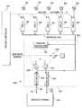
- FIG. 1illustrates a split ratio fluid process control system according to one embodiment of the present invention that is adapted to provide a predetermined flow of process fluid to a pair of fluid outlets;
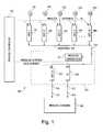
- FIG. 2illustrates a split ratio fluid process control system according to another embodiment of the present invention that is adapted to provide a predetermined flow of process fluid to a pair of fluid outlets;
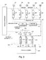
- FIG. 3illustrates a split ratio fluid process control system according to yet another embodiment of the present invention that is adapted to provide a predetermined flow of process fluid to more than two fluid outlets;
- FIG. 4illustrates a split ratio fluid process control system according to yet another embodiment of the present invention that utilizes critical flow nozzles and provides a predetermined flow of process fluid to a pair of fluid outlets;
- FIG. 5illustrates a split ratio fluid process control system according to yet another embodiment of the present invention that is similar to the embodiment of FIG. 2 and which does not include a PID controller;
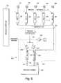
- FIG. 6illustrates a split ratio fluid process control system according to yet another embodiment of the present invention that is similar to the embodiment of FIG. 3 and which does not include a PID controller;
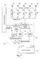
- FIG. 7illustrates a split ratio fluid process control system according to yet another embodiment of the present invention that utilizes a proportional diverter valve.
- fluidis used to refer to fluids in a liquid state, fluids in a gaseous state, and to slurries (e.g., fluids in a liquid state with solids suspended therein).
- slurriese.g., fluids in a liquid state with solids suspended therein.
- process fluids in usemay be a single species of process fluid, or may be a mixture of different process fluid species.
- FIG. 1illustrates a split ratio fluid process control system according to one embodiment of the present invention that is adapted for use with fluids in a gaseous state. Modifications that may be made to this fluid process control system for use with other types of fluids, such as liquids are discussed further below.
- the split ratio fluid process control systemincludes a split ratio controller having a fluid inlet and a plurality of fluid outlets.
- the split ratio controlleris capable of receiving a flow of process fluid at the fluid inlet and providing a plurality of flows of the process fluid to each of the plurality of fluid outlets.
- Each of the plurality of flows of the process fluidmay provide a predetermined amount of the process fluid.
- fluid processing system 100includes a plurality of fluid supplies 131 - 13 N (labeled S 1 -SN), each providing a process fluid or mixture of process fluids to a respective mass flow controller (MFC) 141 - 14 N (labeled MFC 1 -MFCN).
- MFCmass flow controller
- fluid supply S 1could be Nitrogen
- fluid supply S 2could be Argon
- fluid supply S 3could be Helium
- fluid supply S 4 silaneetc.
- Each mass flow controller 141 - 14 Nreceives a flow of fluid (or fluids) from its respective fluid supply and setpoint from a process controller 110 . Based upon the setpoint received from the process controller 110 , each MFC 141 - 14 N provides a metered amount of fluid to a common manifold 150 .
- the split ratio controller 120has a fluid inlet 155 that is fluidly coupled to the common manifold 150 to receive a flow of process fluid or fluids from the common manifold 150 , and a plurality of fluid outlets 156 , 157 . Each of the plurality of fluid outlets 156 , 157 may be coupled to a respective fluid input 151 , 152 of the process chamber 160 to provide a predetermined amount of fluid to the process chamber 160 .
- the split ratio controllermay include a pressure transducer 121 that is fluidly coupled to the common manifold 150 , a mass flow controller 123 , and a pressure controller (P.C.) 129 .
- the pressure transducer 121provides a signal indicative of the pressure within the common manifold 150 to the pressure controller 129 .
- the process controller 110sends a pressure setpoint control signal to the pressure controller 129 that identifies the desired pressure within the common manifold 150 .
- the pressure setpoint provided by the process controller 110is a fixed value during a given process step, although it may change from step to step or during a given processing step. In general, the value of the pressure setpoint will vary depending upon the chamber pressure of the process chamber 160 .
- the pressure setpointmay be set to a value that is several times that of the process chamber to ensure an appropriate flow of process fluid or fluids in the mass flow controller 123 and the pressure controller 129 .
- a pressure difference of approximately 10 torrmay be sufficient.
- the pressure setpointmay be set to any value that permits the required flow through the controllers involved, (e.g., controllers 141 - 14 N, 123 , and 129 ), and this value may vary based upon a variety of factors.
- the process controller 110also provides a split setpoint to the mass flow controller 123 (labeled as MFCX) that is indicative of the amount of process fluid from the manifold 150 that is to be provided to a first input 151 of the process chamber 160 .
- MFCXmass flow controller
- the remaining portion of process fluidis provided via the pressure controller 129 to the second input 152 of the process chamber 160 .
- the pressure controller 129Based upon the signal provided by the pressure transducer 121 and the pressure setpoint provided by the process controller 110 , the pressure controller 129 operates to maintain the pressure within the manifold upstream of MFCX 123 and pressure controller 129 at a constant value. Operation of the split ratio controller 120 will now be described.
- the process controller 110provides a process setpoint to one or more of the mass flow controllers 141 - 14 N to flow a desired amount of fluid.
- the process controller 110also provides a pressure setpoint value to the pressure controller 129 that is indicative of the desired pressure of fluid within the manifold 150 being provided by one or more of the mass flow controllers 141 - 14 N.
- the process controller 110then provides a split setpoint to the mass flow controller 123 (MFCX) that is indicative of the amount of fluid being provided to the common manifold 150 that is desired to be provided to input 151 of the process chamber 160 .
- MFCXmass flow controller 123
- the process controller 110may set the split setpoint according to the following equation, where the mass flow controller 123 (MFCX) is a mass flow controller that has been calibrated on a known process fluid, such as Nitrogen.
- MFCXmass flow controller 123
- Kis the desired split ratio (0 . . . 1)
- S iis the setpoint to MFCi (e.g., MFCs 141 - 14 N)
- F iis a calibration factor calculated as
- the process controller 110sets the split setpoint by calculating the total amount of fluid provided to the common manifold 150 , in terms of a Nitrogen equivalent, during a given process step, and then multiplying that amount of fluid by the desired split ratio K. It should be appreciated that in this embodiment, the process controller 110 would calculate the desired split setpoint for each process step that provides a different amount of fluid or different types of fluids. It should further be appreciated that if the range of flow of fluid (fluids) that is to be provided to the process chamber is too wide, then mass flow controller MFCX could be replaced with two separate mass flow controllers, one for high rates of flow, and another for lower rates of flow.
- the split setpointmay be determined based upon a fluid species other than Nitrogen, provided that the full scale range of each of the mass flow controllers 141 - 14 N and the mass flow controller 123 (MFCX) is known on a particular fluid species, and that each of the mass flow controllers 141 - 14 N and the mass flow controller 123 (MFCX) can reliably operate with the actual fluid species used under the process operating conditions.
- a number of alterationsmay be made to the split ratio fluid process control system described above with respect to FIG. 1 .
- a mechanical pressure regulatorcould be used instead to control the upstream pressure within the manifold 150 .
- pressure transducer 121could be eliminated, and pressure controller 129 could be replaced with a flow restriction device, such as a nozzle.
- a myriad of alternative configurationsmay be used to provide a predetermined amount of fluid to each of the fluid outlets 156 and 157 , so long as: 1) at a maximum outlet pressure, and a maximum amount of flow through the pressure controller 129 and a minimum amount of flow through mass flow controller 123 , the manifold pressure is low enough for each of the supply MFCs 141 - 14 N to function properly; and 2) at any outlet pressure within the operating range, and a minimum amount of flow through the pressure controller 129 and a maximum amount of flow through mass flow controller 123 , the manifold pressure is sufficient for the mass flow controller 123 to function properly and low enough for each of the supply MFCs 141 - 14 N to function properly.
- alternative configurationswould likely have a poorer transient response than the embodiment described with respect to FIG. 1, their reduced cost may be attractive in certain fluid supply systems.
- FIG. 1was described with respect to the flow of a process gas or gases, the present invention is not so limited.
- the embodiment of FIG. 1may be adapted for use with liquids, or with slurries.
- an accumulatormay be added upstream of the fluid inlet 155 and a volumetric controller may be used instead of mass flow controller 123 .
- mass flow controller 123may be used instead of mass flow controller 123 .
- Other modifications necessary for use with incompressible fluidswill be readily appreciated by those skilled in the art.
- slurriesthose of skill in the art will appreciate that great care will need to be taken in the selection of valves, such that the suspended solids that are present in the slurry do not damage the valve or prevent its proper operation
- a fluid processing systemthat dispenses with the need for the process controller 110 to calculate the total amount of fluid, in terms of Nitrogen equivalent, that is provided to the common manifold 150 .
- the split ratio fluid process control systemincludes a split ratio controller having a fluid inlet and a plurality of fluid outlets.
- the split ratio controlleris capable of receiving a flow of process fluid at the fluid inlet and providing a plurality of flows of the process fluid to each of the plurality of fluid outlets.
- Each of the plurality of flows of the process fluidmay have a predetermined ratio relative to the total amount of the process fluid received at the fluid inlet.
- fluid processing system 200 depicted in FIG. 2includes a plurality of fluid supplies 131 - 13 N (labeled S 1 -SN), each providing a process fluid or mixture of process fluids to a respective mass flow controller (MFC) 141 - 14 N (labeled MFC 1 -MFCN).
- MFCmass flow controller
- each mass flow controller 141 - 14 Nreceives a flow of fluid (or fluids) from its respective fluid supply and a setpoint from a process controller 210 .
- each MFC 141 - 14 NBased upon the setpoint received from the process controller 210 , each MFC 141 - 14 N provides a metered amount of fluid to a common manifold 250 .
- the process controller 210 of FIG. 2is programmed to control each of the MFCs 141 - 14 N to provide various amounts of one or more of the fluids during each of a number of processing steps in a conventional manner.
- the split ratio controller 220may include a pressure transducer 221 that is fluidly coupled to the common manifold 250 , a first split ratio mass flow controller 223 (labeled as Split MFC A), a second split ratio mass flow controller 224 (labeled as Split MFC B), first and second multipliers 226 , 227 , a subtraction circuit 229 , and a proportional-integral-derivative (PID) controller 222 .
- a pressure transducer 221that is fluidly coupled to the common manifold 250
- a first split ratio mass flow controller 223labeleled as Split MFC A
- a second split ratio mass flow controller 224labele.g., a second split ratio mass flow controller 224
- first split ratio MFC A 223 and second split ratio MFC B 224are similar MFCs, tuned to have similar response characteristics, although the full-scale range of these MFCs may differ.
- MFC Bwill be used to provide relatively small portion of the flow of process fluid
- the full-scale range of MFC Bmay be selected to be less than the full-scale range of MFC A, so that greater accuracy is provided for the range of anticipated flow rates.
- the first and second split ratio MFCs 223 , 224preferably have their flow sensors disposed downstream of the valve (within each mass flow controller), rather than upstream, so that they are isolated from pressure transients in the common manifold 250 .
- controller 222is described herein as a proportional-integral-derivative (PID) controller, it should be appreciated that the present invention is not so limited.
- PID controllerproportional-integral-derivative
- many other types of feedback controllers other than a PID controllermay be used, such as and Integral-Differential (ID) controller, a Lead-Lag (LL) controller, or a Gain-Lead-Lag (GLL) controller, etc.
- pressure transducer 221provides a signal indicative of the pressure within the common manifold 250 .
- the pressure signalis provided to the PID controller 222 , which also receives a pressure setpoint control signal from the process controller 220 that identifies the desired pressure within the common manifold 250 .
- the pressure setpoint provided by the process controller 210is a fixed value during a given process step, although it may change from step to step or during a given processing step, as described above with respect to FIG. 1 .
- the pressure setpointshould be set to a value that is within a range in which both the supply MFCs 141 - 14 N and the split ratio MFCs 223 and 224 can operate properly, and preferably near the lower end of this range, to optimize system response characteristics.
- the PID controller 222Based upon the signal from the pressure transducer 221 and the pressure setpoint signal from the process controller 210 , the PID controller 222 provides an aggregate setpoint signal to each of the two multipliers 226 and 227 .
- the process controller 210provides a split ratio setpoint to the first multiplier 226 and to the subtraction circuit 229 .
- the split ratio setpointis indicative of the portion or fraction of process fluid within the manifold 250 that is to be provided to a first inlet 151 of the process chamber 160 .
- the split ratio setpointmay be a value between zero and one, inclusive, representing the percentage of the total flow that is desired to be provided to the first input 151 .
- the first multiplier 226multiplies the aggregate setpoint from the PID controller 222 by the split ratio setpoint to provide a first setpoint signal to the first split ratio MFC A 223 .
- the split ratio setpoint from the process controller 210is also provided to the subtraction circuit 229 , which subtracts the value of the split ratio setpoint from 1 to provide a second split ratio setpoint to the second multiplier 227 .
- the second multiplier 227multiples the aggregate setpoint from the PID controller 222 by the second split ratio setpoint to provide a second setpoint signal to the second split ratio MFC B 224 . Operation of the split ratio controller 220 will now be described.
- each MFC 141 - 14 Nprovides a metered amount of fluid, under control of a respective process setpoint received from the process controller 210 .
- These fluidsare mixed in the common manifold 250 connecting the outputs of MFC 141 - 14 N, and the fluid mixture flows into the inlet of the split ratio controller 220 .
- the process controller 210provides an appropriate setpoint to each MFC 141 - 14 N, and a split ratio setpoint (between 0 and 1) to the split ratio controller 220 , for the appropriate time.
- the PID controller 222produces an aggregate setpoint such that, during a process step, the pressure in the manifold 250 matches the pressure setpoint.
- the pressure setpointmay be a constant (for example 50 to 100 Torr), or may be provided by the process controller 210 and varied from step to step.
- the aggregate setpoint from the PID controller 222reflects the total flow rate into the common manifold 250 . That aggregate setpoint is then split based on the split ratio setpoint from the process controller 210 .
- first multiplier 226provides a setpoint of 0.6*0.3 (i.e., 0.18) to the first split ratio MFC A 223
- second multiplier 227provides a setpoint of 0.6*(1 ⁇ 0.3) (i.e., 0.42) to the second split ratio MFC B 224 , based upon the subtraction performed by subtraction circuit 229 .
- Split ratio MFC A 223will then flow 18% of full scale, and split ratio MFC B will flow 42% of full scale.
- split ratio MFC A 223flows 30% of the total, as requested by the split ratio setpoint, with split ratio MFC B 224 providing the remainder. If the aggregate setpoint were to increase to 0.7, split ratio MFC A 223 would see a setpoint of 0.7*0.3 (i.e., 0.21), and split ratio MFC B 224 would see a setpoint Of 0.7*(1 ⁇ 0.3) (i.e., 0.49), and the total flow through the split ratio MFCs A and B 223 , 224 would increase to 70% of full-scale.
- the PID controller 222then servos such that total flow through the split ratio MFCs 223 , 224 is precisely equal to the total flow from the supply MFCs 141 - 14 N. If the aggregate setpoint is a bit too low, the manifold pressure, as measured by the pressure transducer 221 will begin to increase, and the PID controller 222 will increase the aggregate setpoint to compensate. If the aggregate setpoint is a bit too high, the manifold pressure will decrease, and the PID controller 222 will decrease the aggregate setpoint to compensate.
- the aggregate setpointcould be calculated as the sum of a setpoint from the process controller 210 and the output of the PID controller 222 . This could improve the system's dynamic response by giving the controllers advance notice that the fluid coming into the manifold is changing. However, it could complicate the programming of the process controller 210 , by requiring the process controller to calculate a total N2-equivalent flow from the process setpoints being sent to all the process MFCs. It should also be appreciated that the embodiment described above with respect to FIG. 2 may be adapted for use with incompressible fluids, such as liquids, and with slurries.
- a fluid processing systemthat includes two or more outlet ports leading to respective inlet ports of a process chamber.
- a fluid processing systemthat includes three outlet ports is now described with respect to FIG. 3 .
- FIG. 3As many features of this embodiment are similar to those described above with respect to the embodiment of FIG. 2, only differences between these two embodiments will be explained in detail, during a description of the operation of this further embodiment.
- each MFC 141 - 14 Nprovides a metered amount of fluid, under control of a respective process setpoint received from the process controller 310 .
- These fluidsare mixed in the common manifold 350 connecting the outlets of MFC 141 - 14 N, and the fluid mixture flows into an inlet 155 of the split ratio controller 320 .
- the process controller 310provides an appropriate setpoint to each MFC 141 - 14 N, and a plurality of split ratio setpoints to the split ratio controller 320 , for the appropriate time.
- the PID controller 322produces an aggregate setpoint such that, during a process step, the pressure in the manifold 350 matches a pressure setpoint.
- the pressure setpointmay be a constant or may be provided by the process controller 310 and varied from step to step.
- the aggregate setpoint from the PID controller 322reflects the total flow rate into the common manifold 350 . That aggregate setpoint is then split based on each of the plurality of split ratio setpoints from the process controller 310 .
- the first multiplier 326provides a setpoint of 0.6*0.2 (i.e., 0.12) to the first split ratio MFC Z 323
- the second multiplier 327provides a setpoint of 0.6*(0.3) (i.e., 0.18) to the second split ratio MFC B 324
- the third multiplier 328provides a setpoint of 0.6*0.5 (i.e., 0.30) to the third split ratio MFC A 325 .
- the ratio inputs to the multipliersneed not even add up to 1.
- the same 20%:30%:50% splitmay be obtained by feeding the first split ratio MFC with 40% of the aggregate setpoint, the second with 60% of the aggregate setpoint, and the third with 100% of the aggregate setpoint.
- the PID controller 222would ultimately settle out to a different value, but each split ratio MFC would ultimately end up flowing the same amount of fluid as in the previous example.
- a subtraction circuit similar to subtraction circuit 229 in FIG. 2may be used to determine the setpoint of any one of the split ratio MFCs.
- the split ratio setpoints provided to the first and second multipliers 326 and 327may first be summed and then provided to the subtraction circuit to provide a split ratio setpoint to multiplier 328 .
- Other configurationsmay also be considered.
- split ratio controller 320described above with respect to FIG. 3 was described as having three outlet ports, it should be appreciated that it may be readily extended to systems having more than three fluid outlet ports. Indeed, as long as the desired split ratio may be decomposed into multiple values in the proper ratios, and each of those values are multiplied by the composite (aggregate) setpoint, additional fluid outlet ports may be accommodated.
- each output porthas its own split ratio MFC
- the setpoints to the split ratio MFCsare at the proper ratio relative to each other, and that the setpoints to all split ratio MFCs servo together to maintain a desired manifold pressure.
- a fluid processing systemincludes a split ratio controller that dispenses with the use of one or more mass flow controllers therein. This further embodiment is now described with respect to FIG. 4 .
- fluid processing system 400 depicted in FIG. 4includes a plurality of fluid supplies 131 - 13 N (labeled S 1 -SN), each providing a process fluid or mixture of process fluids to a respective mass flow controller (MFC) 141 - 14 N (labeled MFC 1 -MFCN).
- MFCmass flow controller
- each mass flow controller 141 - 14 Nreceives a flow of fluid (or fluids) from its respective fluid supply and a setpoint from a process controller 410 .
- each MFC 141 - 14 NBased upon the setpoint received from the process controller 410 , each MFC 141 - 14 N provides a metered amount of fluid to a common manifold 450 .
- the process controller 410 of FIG. 4is programmed to control each of the MFCs 141 - 14 N to provide various amounts of one or more of the fluids during each of a number of processing steps in a conventional manner.
- the split ratio controller 420may include a pressure transducer 421 that is fluidly coupled to the common manifold 450 , a pulse width modulation (PWM) controller 422 .
- PWMpulse width modulation
- each of the control valves 426 and 427are digital control valves.
- the first and second critical flow nozzles 423 , 424are preferably substantially identical and are fluidly coupled to the common manifold 450 . Provided that a pressure ratio of approximately 2:1 is maintained across each of the critical flow nozzles 423 , 424 , the flow through each of the critical flow nozzles will be substantially identical and may be controlled by modulating the amount of time each of the valves 426 and 427 is in an open state. The open state of each of the valves 426 and 427 may be controlled based upon the frequency that each valve is opened, the duration of time that each valve is opened, or both.
- each of the critical flow nozzles 423 , 424is controlled via control valves 426 and 427 , respectively.
- Each of control valves 426 , 427respectively receives a pulse width modulated control signal 428 , 429 from the PWM controller 422 that controls the duration (width or W) and the frequency (pulse or P) of the opening of the valves 426 , 427 .
- the frequency (P) and duration (W) of each of the valvesis determined by two factors: the upstream pressure as indicated by the pressure transducer 421 and set via the pressure setpoint from the process controller 410 , and the desired split ratio setpoint signal provided by the process controller 410 .
- the duration (W) of each of the valves 426 and 427may be the same, with the frequency being adjusted to provide the desired ratio of fluid to each of the outlets 156 and 157 .
- the frequency of valve 427would be the frequency of valve 426 times 60 divided by 40 (i.e., 1.5 times the frequency of valve 426 ).
- the duration (W) of the on state of both valves 426 and 427would be determined based upon the upstream pressure. The duration would increase or decrease to maintain the desired upstream pressure.
- the frequency of the control signals 428 , 429 provided to each of the valves 426 , 427may be the same, and the duration (W) adjusted to provide the desired ratio of fluid.
- both the duration (W) and the frequency (P)may be adjusted to provide the desired ratio of fluid to each of the outlets.
- first and second critical flow nozzles 423 and 424have been described as being substantially identical to one another, it should be appreciated that some differences will inevitably exist. However, each of the critical flow nozzles may be characterized and the PWM controller 422 programmed to apply a correction algorithm to make them identical. For example, the frequencies (or the duration) of the control signals 428 and 429 could be slightly adjusted based upon a characterization of the critical flow nozzles. Thus, although the critical flow nozzles are preferably substantially identical, the present invention is not so limited.
- FIGS. 5 and 6illustrate alternative embodiments of the present invention, that are similar to the embodiments described above with respect to FIGS. 2 and 3, respectively, but in which the PID controller 222 , 322 is omitted.
- the omission of the PID controllers 222 , 322is functionally equivalent to providing a PID controller having a proportional gain (P) of unity (1), Integral (I) and differential (D) gains of zero (0), and providing a pressure setpoint of zero (0) from the process controller.
- Pproportional gain
- IIntegral
- Ddifferential
- a pressure transducer 521 , 621provides a signal indicative of the pressure within the common manifold 550 , 650 to each of multipliers 526 and 527 (FIG. 5 ), and 626 , 627 , 628 (FIG. 6 ).
- the process controller 510provides a split ratio setpoint to the first multiplier 526 and to a subtraction circuit 529 .
- the split ratio setpointis indicative of the portion or fraction of process fluid within the manifold 550 that is to be provided to a first inlet 151 of the process chamber 160 .
- the split ratio setpointmay be a value between zero and one, inclusive, representing the percentage of the total flow that is desired to be provided to the first input 151 .
- the first multiplier 526multiplies the split ratio setpoint by the signal indicative of the pressure within the common manifold 550 to provide a first setpoint signal to a first split ratio MFC A 523 .
- the split ratio setpoint from the process controller 510is also provided to the subtraction circuit 529 , which subtracts the value of the split ratio setpoint from 1 to provide a second split ratio setpoint to the second multiplier 527 .
- the second multiplier 527multiples the second split ratio setpoint by the signal indicative of the pressure within the common manifold 550 to provide a second setpoint signal to the second split ratio MFC B 524 .
- the process controller 610provides a plurality of split ratio setpoints to the split ratio controller 620 for the appropriate time.
- Each of these split ratio setpointsis provided to a respective multiplier 626 , 627 , 628 , which receives the respective split ratio setpoint and multiplies the respective split ratio setpoint by the signal indicative of the pressure within the common manifold 650 received from the pressure transducer 621 .
- Each of the multipliers 626 , 627 , 628then provides a respective setpoint signal to a respective split ratio MFC 623 , 624 , 625 that reflects the desired ratio of fluid that is to be provided by the respective split ratio MFC.
- the split ratio fluid process control systemincludes a split ratio controller having a proportional diverter valve controllable to divide the flow of process fluid between two fluid outlets, a pair of flow meters to measure the flow of process fluid through each fluid outlet, and a control system to control the ratio of the flow of process fluid between the two fluid outlets.
- fluid processing system 700 depicted in FIG. 7includes a plurality of fluid supplies 131 - 13 N (labeled S 1 -SN), each providing a process fluid or mixture of process fluids to a respective mass flow controller (MFC) 141 - 14 N (labeled MFC 1 -MFCN).
- MFCmass flow controller
- each mass flow controller 141 - 14 Nreceives a flow of fluid (or fluids) from its respective fluid supply and a setpoint from a process controller 710
- each MFC 141 - 14 Nprovides a metered amount of fluid to a common manifold 750 .
- the process controller 710 of FIG. 7is programmed to control each of the MFCs 141 - 14 N to provide various amounts of one or more of the fluids during each of a number of processing steps in a conventional manner.
- the split ratio controller 720may include a proportional diverter valve 701 that is fluidly coupled to the common manifold 750 , a first flow meter 702 (labeled as Flow Meter A), a second flow meter 703 (labeled as Flow Meter B), an adder 706 , a divider 708 , and a controller 722 .
- first flow meter A 702 and second flow meter B 703are similar flow meters, tuned to have similar response characteristics.
- controller 722is described herein as a proportional-integral-derivative (PID) controller, it should be appreciated that the present invention is not so limited.
- PID controllersmany other types of feedback controllers other than a PID controller may be used, such as a Lead-Lag (LL) controller or a Gain-Lead-Lag (GLL) controller, etc.
- the proportional diverter valve 701is an always-open valve that divides its inlet flow selectively between 2 outlets, under control of valve drive signal 711 . Either outlet may be closed off, but only one outlet can be closed at a time. It should be appreciated that a variety of different types of valves may be used for this purpose, such as a disc valve, a ball valve, a cartridge valve, a solenoid controlled valve, etc., as the present invention is not limited to any particular type of valve.
- One outlet of proportional diverter valve 701is fluidly coupled to the inlet of flow meter A 702 , and the other outlet is fluidly coupled to the inlet of flow meter B 703 .
- Flow meter Aprovides an indicated flow A output signal 704 that is connected to a first input of adder 706 and a first input of divider 708 .
- Flow meter Bprovides an indicated flow B output signal 705 that is connected to a second input of adder 706 .
- Adder 706provides a total flow signal 707 that is connected to a second input of divider 708 .
- Divider 708calculates a ratio feedback signal 709 (i.e., indicated flow A/(indicated flow A+indicated flow B)) that is connected to a feedback input of PID controller 722 .
- the process controller 710provides a split ratio setpoint signal 712 to a setpoint input of PID controller 722 .
- PID controller 722Based upon these signals, PID controller 722 provides a valve drive signal 711 that controls the fluid split provided by the proportional diverter valve 701 . Operation of the split ratio controller 720 will now be described.
- each MFC 141 - 14 Nprovides a metered amount of fluid, under control of a respective process setpoint received from the process controller 710 .
- These fluidsare mixed in the common manifold 750 connecting the outputs of MFC 141 - 14 N, and the fluid mixture flows into the inlet 155 of the split ratio controller 720 .
- the process controller 710provides an appropriate setpoint to each MFC 141 - 14 N, and a split ratio setpoint (between 0 and 1) to the split ratio controller 720 , for the appropriate time.
- the proportional diverter valve 701divides the inlet fluid flow from manifold 750 between its two outlets, under control of valve drive signal 711 . It should be appreciated that immediately following a setpoint, flow, or fluid species change, the split provided by valve 701 may not precisely match the split requested by the process controller 710 .
- Flow meter A 702 and flow meter B 703measure the actual flow of process fluid from each of the two outlets of the proportional diverter valve 701 , and provide indicated flow signals A and B 704 , 705 . It should be appreciated that these flow signals are representative of the flow of process fluid provided to each fluid input of the process chamber 160 .
- the adder 706calculates total flow 707 through split ratio controller 720 by summing indicated flow signals A and B 704 , 705 .
- Divider 708calculates the ratio feedback signal 709 by dividing indicated flow signal A 704 by the total flow signal 707 .
- PID controller 722compares the split ratio setpoint signal 712 with the ratio feedback signal 709 and servos, adjusting valve drive signal 711 , such that the ratio feedback signal 709 is equal to the split ratio setpoint signal 712 . If the ratio feedback signal 709 is a bit too low, the PID controller 722 will increase the valve drive signal 711 to compensate. Similarly, if the ratio feedback signal 709 is a bit too high, the PID controller 722 will decrease the valve drive signal 711 to compensate.
- split ratio controller 720described above with respect to FIG. 7 included a divider 708 that determined a ratio feedback signal 709 based upon the indicated flow signal A divided by the sum of the indicated flow signals A and B, and the PID controller 712 compared the ratio feedback signal 709 to the split ratio setpoint signal 712
- similar functionalitycould be provided with a multiplier.
- divider Acould be substituted with a multiplier that calculates a flow setpoint based upon the split ratio setpoint signal 712 multiplied by the total flow signal 707 .
- the PID controller 722could then compare the desired flow signal A with this alternative flow setpoint signal to provide similar functionality.
- valve 701may be connected in the opposite manner, and the valve drive signal 711 inverted to compensate.
Landscapes
- Physics & Mathematics (AREA)
- General Physics & Mathematics (AREA)
- Engineering & Computer Science (AREA)
- Automation & Control Theory (AREA)
- Flow Control (AREA)
- Feeding, Discharge, Calcimining, Fusing, And Gas-Generation Devices (AREA)
Abstract
Description

Claims (21)
Priority Applications (5)
| Application Number | Priority Date | Filing Date | Title |
|---|---|---|---|
| US10/154,433US6752166B2 (en) | 2001-05-24 | 2002-05-23 | Method and apparatus for providing a determined ratio of process fluids |
| US10/832,949US6941965B2 (en) | 2001-05-24 | 2004-04-27 | Method and apparatus for providing a determined ratio of process fluids |
| US11/174,753US7143774B2 (en) | 2001-05-24 | 2005-07-05 | Method and apparatus for providing a determined ratio of process fluids |
| US11/504,175US7424894B2 (en) | 2001-05-24 | 2006-08-15 | Method and apparatus for providing a determined ratio of process fluids |
| US11/651,231US7360551B2 (en) | 2001-05-24 | 2007-01-09 | Method and apparatus for providing a determined ratio of process fluids |
Applications Claiming Priority (2)
| Application Number | Priority Date | Filing Date | Title |
|---|---|---|---|
| US29335601P | 2001-05-24 | 2001-05-24 | |
| US10/154,433US6752166B2 (en) | 2001-05-24 | 2002-05-23 | Method and apparatus for providing a determined ratio of process fluids |
Related Child Applications (2)
| Application Number | Title | Priority Date | Filing Date |
|---|---|---|---|
| US10/832,949ContinuationUS6941965B2 (en) | 2001-05-24 | 2004-04-27 | Method and apparatus for providing a determined ratio of process fluids |
| US10/832,949DivisionUS6941965B2 (en) | 2001-05-24 | 2004-04-27 | Method and apparatus for providing a determined ratio of process fluids |
Publications (2)
| Publication Number | Publication Date |
|---|---|
| US20020179148A1 US20020179148A1 (en) | 2002-12-05 |
| US6752166B2true US6752166B2 (en) | 2004-06-22 |
Family
ID=23128747
Family Applications (5)
| Application Number | Title | Priority Date | Filing Date |
|---|---|---|---|
| US10/154,433Expired - LifetimeUS6752166B2 (en) | 2001-05-24 | 2002-05-23 | Method and apparatus for providing a determined ratio of process fluids |
| US10/832,949Expired - LifetimeUS6941965B2 (en) | 2001-05-24 | 2004-04-27 | Method and apparatus for providing a determined ratio of process fluids |
| US11/174,753Expired - LifetimeUS7143774B2 (en) | 2001-05-24 | 2005-07-05 | Method and apparatus for providing a determined ratio of process fluids |
| US11/504,175Expired - LifetimeUS7424894B2 (en) | 2001-05-24 | 2006-08-15 | Method and apparatus for providing a determined ratio of process fluids |
| US11/651,231Expired - Fee RelatedUS7360551B2 (en) | 2001-05-24 | 2007-01-09 | Method and apparatus for providing a determined ratio of process fluids |
Family Applications After (4)
| Application Number | Title | Priority Date | Filing Date |
|---|---|---|---|
| US10/832,949Expired - LifetimeUS6941965B2 (en) | 2001-05-24 | 2004-04-27 | Method and apparatus for providing a determined ratio of process fluids |
| US11/174,753Expired - LifetimeUS7143774B2 (en) | 2001-05-24 | 2005-07-05 | Method and apparatus for providing a determined ratio of process fluids |
| US11/504,175Expired - LifetimeUS7424894B2 (en) | 2001-05-24 | 2006-08-15 | Method and apparatus for providing a determined ratio of process fluids |
| US11/651,231Expired - Fee RelatedUS7360551B2 (en) | 2001-05-24 | 2007-01-09 | Method and apparatus for providing a determined ratio of process fluids |
Country Status (7)
| Country | Link |
|---|---|
| US (5) | US6752166B2 (en) |
| EP (1) | EP1399789A1 (en) |
| JP (3) | JP4209688B2 (en) |
| KR (1) | KR20040019293A (en) |
| CN (1) | CN100403198C (en) |
| TW (1) | TW573240B (en) |
| WO (1) | WO2002095519A1 (en) |
Cited By (52)
| Publication number | Priority date | Publication date | Assignee | Title |
|---|---|---|---|---|
| US20040112538A1 (en)* | 2002-12-13 | 2004-06-17 | Lam Research Corporation | Gas distribution system with tuning gas |
| US20040168719A1 (en)* | 2003-02-28 | 2004-09-02 | Masahiro Nambu | System for dividing gas flow |
| US6796332B1 (en)* | 2003-04-04 | 2004-09-28 | Texaco Inc | Fluid balance control system for use in a fuel processor |
| US20040187928A1 (en)* | 2002-01-04 | 2004-09-30 | Jesse Ambrosina | Mass flow ratio system and method |
| US20050029369A1 (en)* | 2003-06-09 | 2005-02-10 | Hideki Nagaoka | Partial pressure control system, flow rate control system and shower plate used for partial pressure control system |
| US20060097644A1 (en)* | 2003-06-09 | 2006-05-11 | Ckd Corporation | Relative pressure control system and relative flow control system |
| US20060123134A1 (en)* | 1998-10-30 | 2006-06-08 | Science Applications International Corporation | Agile network protocol for secure communications with assured system availability |
| US20060207595A1 (en)* | 2003-10-06 | 2006-09-21 | Tadahiro Ohmi | Internal pressure controller of chamber and internal pressure subject -to- control type chamber |
| US20060237063A1 (en)* | 2005-04-21 | 2006-10-26 | Junhua Ding | Gas delivery method and system including a flow ratio controller using antisymmetric optimal control |
| US20060276857A1 (en)* | 2003-10-02 | 2006-12-07 | Medtronic, Inc. | Medical device programmer with infrared communication |
| US20070107783A1 (en)* | 2001-05-24 | 2007-05-17 | Lull John M | Method and apparatus for providing a determined ratio of process fluids |
| US20070186983A1 (en)* | 2005-04-21 | 2007-08-16 | Junhua Ding | Gas delivery method and system including a flow ratio controller using a multiple antisymmetric optimal control arrangement |
| US20070193628A1 (en)* | 2003-07-31 | 2007-08-23 | Hiroshi Kannan | Gas Supply Facility Of A Chamber And A Fethod For An Internal Pressure Control Of The Chamber For Which The Facility Is Employed |
| US20080005792A1 (en)* | 1998-10-30 | 2008-01-03 | Science Applications International Corporation | Method for establishing secure communication link between computers of virtual private network |
| US20080040792A1 (en)* | 1998-10-30 | 2008-02-14 | Virnetx, Inc. | Agile network protocol for secure communications using secure domain names |
| US20080115834A1 (en)* | 2006-11-20 | 2008-05-22 | Applied Materials, Inc. | System and method to divide fluid flow in a predetermined ratio |
| US20080202609A1 (en)* | 2007-02-26 | 2008-08-28 | Ezra Robert Gold | Method and apparatus for controlling gas flow to a processing chamber |
| US20080202588A1 (en)* | 2007-02-26 | 2008-08-28 | Ezra Robert Gold | Method and apparatus for controlling gas flow to a processing chamber |
| US20080222415A1 (en)* | 1998-10-30 | 2008-09-11 | Virnetx, Inc. | Agile network protocol for secure communications with assured system availability |
| US20090059717A1 (en)* | 2007-08-31 | 2009-03-05 | Ckd Corporation | Fluid mixing system and fluid mixing apparatus |
| US20090084194A1 (en)* | 2007-09-28 | 2009-04-02 | Robert Shock | Coriolis dosing system for filling gas cylinders |
| US20090095364A1 (en)* | 2007-10-15 | 2009-04-16 | Ckd Corporation | Fluid flow distribution and supply unit and flow distribution control program |
| US20090178714A1 (en)* | 2008-01-14 | 2009-07-16 | Tokyo Electron Limited | Flow control system and method for multizone gas distribution |
| US20110005601A1 (en)* | 2007-12-27 | 2011-01-13 | Lam Research Corporation | Gas transport delay resolution for short etch recipes |
| US20110135821A1 (en)* | 2009-12-07 | 2011-06-09 | Junhua Ding | Methods of and apparatus for controlling pressure in multiple zones of a process tool |
| TWI386770B (en)* | 2008-05-21 | 2013-02-21 | Fujikin Kk | And a discontinuous flow rate switching control method using a fluid of the pressure type flow control device |
| US20130199728A1 (en)* | 2004-07-26 | 2013-08-08 | Hiroyuki Kobayashi | Plasma processing apparatus |
| US20130255784A1 (en)* | 2012-03-30 | 2013-10-03 | Applied Materials, Inc. | Gas delivery systems and methods of use thereof |
| US20140230910A1 (en)* | 2013-02-20 | 2014-08-21 | Agilent Technologies, Inc. | Split-channel gas flow control |
| US20150059859A1 (en)* | 2013-08-30 | 2015-03-05 | Fujikin Incorporated | Apparatus for dividing and supplying gas and method for dividing and supplying gas |
| US9285079B2 (en)* | 2011-07-28 | 2016-03-15 | Horiba Stec, Co., Ltd. | Gas supply system |
| US9305810B2 (en) | 2011-06-30 | 2016-04-05 | Applied Materials, Inc. | Method and apparatus for fast gas exchange, fast gas switching, and programmable gas delivery |
| US20160211158A1 (en)* | 2015-01-20 | 2016-07-21 | Infineon Technologies Ag | Tank switch and method of monitoring a fluid rate |
| US20160291610A1 (en)* | 2015-04-06 | 2016-10-06 | Horiba Stec, Co., Ltd. | Flow rate ratio control apparatus and program for flow rate ratio control apparatus |
| US9958302B2 (en) | 2011-08-20 | 2018-05-01 | Reno Technologies, Inc. | Flow control system, method, and apparatus |
| US20180258530A1 (en)* | 2017-03-10 | 2018-09-13 | Horiba Stec, Co., Ltd. | Gas control system, deposition apparatus including gas control system, and program and gas control method used for gas control system |
| US20190085877A1 (en)* | 2017-09-15 | 2019-03-21 | Kabushiki Kaisha Toshiba | Variable pressure device and actuator |
| US10303189B2 (en) | 2016-06-30 | 2019-05-28 | Reno Technologies, Inc. | Flow control system, method, and apparatus |
| US20190279888A1 (en)* | 2018-03-09 | 2019-09-12 | Lam Research Corporation | Mass Flow Controller for Substrate Processing |
| US10511573B2 (en) | 1998-10-30 | 2019-12-17 | Virnetx, Inc. | Agile network protocol for secure communications using secure domain names |
| US10663337B2 (en) | 2016-12-30 | 2020-05-26 | Ichor Systems, Inc. | Apparatus for controlling flow and method of calibrating same |
| US10679880B2 (en) | 2016-09-27 | 2020-06-09 | Ichor Systems, Inc. | Method of achieving improved transient response in apparatus for controlling flow and system for accomplishing same |
| US10838437B2 (en) | 2018-02-22 | 2020-11-17 | Ichor Systems, Inc. | Apparatus for splitting flow of process gas and method of operating same |
| US11003198B2 (en) | 2011-08-20 | 2021-05-11 | Ichor Systems, Inc. | Controlled delivery of process gas using a remote pressure measurement device |
| US11144075B2 (en) | 2016-06-30 | 2021-10-12 | Ichor Systems, Inc. | Flow control system, method, and apparatus |
| US11169547B2 (en)* | 2018-04-28 | 2021-11-09 | Applied Materials, Inc. | Gas-pulsing-based shared precursor distribution system and methods of use |
| US11225719B2 (en) | 2017-12-13 | 2022-01-18 | Horiba Stec, Co., Ltd. | Concentration controller, gas control system, deposition apparatus, concentration control method, and program recording medium for concentration controller |
| US11365480B2 (en)* | 2019-01-28 | 2022-06-21 | Horiba Stec, Co., Ltd. | Concentration control apparatus, zero point adjustment method, and program recording medium recorded with concentration control apparatus program |
| US20220380900A1 (en)* | 2021-05-26 | 2022-12-01 | Asm Ip Holding B.V. | Systems and methods of controlling gas flows in semiconductor processing systems |
| US20220387949A1 (en)* | 2019-11-19 | 2022-12-08 | Linde Gmbh | Smart gas mixer |
| US11899477B2 (en) | 2021-03-03 | 2024-02-13 | Ichor Systems, Inc. | Fluid flow control system comprising a manifold assembly |
| US11940819B1 (en)* | 2023-01-20 | 2024-03-26 | Applied Materials, Inc. | Mass flow controller based fast gas exchange |
Families Citing this family (66)
| Publication number | Priority date | Publication date | Assignee | Title |
|---|---|---|---|---|
| US7563328B2 (en)* | 2001-01-19 | 2009-07-21 | Tokyo Electron Limited | Method and apparatus for gas injection system with minimum particulate contamination |
| US7039999B2 (en)* | 2002-04-25 | 2006-05-09 | Tarr Adam L | Method for installation of semiconductor fabrication tools |
| US7534363B2 (en) | 2002-12-13 | 2009-05-19 | Lam Research Corporation | Method for providing uniform removal of organic material |
| US7201179B2 (en)* | 2003-09-23 | 2007-04-10 | Air Liquide Industrial U.S. Lp | Modular fluid supply system |
| US7461549B1 (en)* | 2007-06-27 | 2008-12-09 | Mks Instruments, Inc. | Mass flow verifiers capable of providing different volumes, and related methods |
| US7394639B2 (en)* | 2005-07-08 | 2008-07-01 | Advanced Energy Industries, Inc. | System and method for driving an industrial control device |
| US8776717B2 (en)* | 2005-10-11 | 2014-07-15 | Intermolecular, Inc. | Systems for discretized processing of regions of a substrate |
| JP4788920B2 (en)* | 2006-03-20 | 2011-10-05 | 日立金属株式会社 | Mass flow control device, verification method thereof, and semiconductor manufacturing device |
| US8997791B2 (en) | 2006-04-14 | 2015-04-07 | Mks Instruments, Inc. | Multiple-channel flow ratio controller |
| JP2008039513A (en)* | 2006-08-03 | 2008-02-21 | Hitachi Metals Ltd | Flow rate control compensation method for mass flow controller |
| US7637143B2 (en)* | 2006-11-10 | 2009-12-29 | Tokyo Electron Limited | Substrate processing apparatus and analysis method therefor |
| US8011317B2 (en)* | 2006-12-29 | 2011-09-06 | Intermolecular, Inc. | Advanced mixing system for integrated tool having site-isolated reactors |
| US7706925B2 (en)* | 2007-01-10 | 2010-04-27 | Mks Instruments, Inc. | Integrated pressure and flow ratio control system |
| AU2008210471B2 (en)* | 2007-01-30 | 2013-01-10 | Bradley University | A heat transfer apparatus and method |
| US20080254217A1 (en)* | 2007-04-16 | 2008-10-16 | Boroson Michael L | Fine control of vaporized organic material |
| US8387657B2 (en)* | 2007-06-15 | 2013-03-05 | Fisher Controls International, Llc | Methods and apparatus to determine a position of a valve |
| KR100951683B1 (en)* | 2007-12-10 | 2010-04-07 | 주식회사 테라세미콘 | Source gas supply method |
| JP4585035B2 (en)* | 2007-12-27 | 2010-11-24 | 株式会社堀場エステック | Flow rate ratio controller |
| US20090236447A1 (en)* | 2008-03-21 | 2009-09-24 | Applied Materials, Inc. | Method and apparatus for controlling gas injection in process chamber |
| US8205629B2 (en)* | 2008-04-25 | 2012-06-26 | Applied Materials, Inc. | Real time lead-line characterization for MFC flow verification |
| US9823666B2 (en)* | 2008-06-26 | 2017-11-21 | Belparts | Flow control system |
| CN102124418B (en)* | 2008-08-13 | 2013-07-03 | 国际壳牌研究有限公司 | Method for controlling a gas flow between a plurality of gas streams |
| US20100084023A1 (en)* | 2008-10-07 | 2010-04-08 | Chris Melcer | Flow control module for a fluid delivery system |
| EP3133636B1 (en) | 2009-06-10 | 2019-01-02 | Entegris, Inc. | Fluid processing systems and method |
| WO2011021539A1 (en)* | 2009-08-20 | 2011-02-24 | 東京エレクトロン株式会社 | Plasma treatment device and plasma treatment method |
| WO2011085064A2 (en)* | 2010-01-08 | 2011-07-14 | Applied Materials, Inc. | N-channel flow ratio controller calibration |
| WO2011097015A2 (en) | 2010-02-03 | 2011-08-11 | Achates Power, Inc. | Rolling thrust bearing constructions |
| WO2011097016A2 (en) | 2010-02-03 | 2011-08-11 | Achates Power, Inc. | Single-crankshaft, opposed-piston engine constructions |
| JP5562712B2 (en)* | 2010-04-30 | 2014-07-30 | 東京エレクトロン株式会社 | Gas supply equipment for semiconductor manufacturing equipment |
| KR101772723B1 (en)* | 2010-06-28 | 2017-08-29 | 도쿄엘렉트론가부시키가이샤 | Plasma processing method |
| US8905074B2 (en)* | 2010-10-22 | 2014-12-09 | Applied Materials, Inc. | Apparatus for controlling gas distribution using orifice ratio conductance control |
| JP5528374B2 (en)* | 2011-03-03 | 2014-06-25 | 東京エレクトロン株式会社 | Gas decompression supply device, cylinder cabinet including the same, valve box, and substrate processing apparatus |
| US8849466B2 (en) | 2011-10-04 | 2014-09-30 | Mks Instruments, Inc. | Method of and apparatus for multiple channel flow ratio controller system |
| CN103591458B (en)* | 2012-08-17 | 2017-04-12 | 诺发系统公司 | Flow balancing in gas distribution networks |
| US8925588B2 (en)* | 2012-08-17 | 2015-01-06 | Novellus Systems, Inc. | Flow balancing in gas distribution networks |
| US9004107B2 (en)* | 2012-08-21 | 2015-04-14 | Applied Materials, Inc. | Methods and apparatus for enhanced gas flow rate control |
| US9781994B2 (en)* | 2012-12-07 | 2017-10-10 | Taiwan Semiconductor Manufacturing Company Limited | Wafer cleaning |
| US9090972B2 (en)* | 2012-12-31 | 2015-07-28 | Lam Research Corporation | Gas supply systems for substrate processing chambers and methods therefor |
| US9335768B2 (en)* | 2013-09-12 | 2016-05-10 | Lam Research Corporation | Cluster mass flow devices and multi-line mass flow devices incorporating the same |
| JP6158111B2 (en)* | 2014-02-12 | 2017-07-05 | 東京エレクトロン株式会社 | Gas supply method and semiconductor manufacturing apparatus |
| CN104514759A (en)* | 2014-12-30 | 2015-04-15 | 天津福云天翼科技有限公司 | High-flow separating accumulator group constant pressure regulating system |
| US10658222B2 (en) | 2015-01-16 | 2020-05-19 | Lam Research Corporation | Moveable edge coupling ring for edge process control during semiconductor wafer processing |
| WO2016130866A1 (en) | 2015-02-12 | 2016-08-18 | Entegris, Inc. | Smart package |
| US10957561B2 (en)* | 2015-07-30 | 2021-03-23 | Lam Research Corporation | Gas delivery system |
| US10261523B2 (en)* | 2015-08-17 | 2019-04-16 | Rainboxx, Inc. | Apparatus and method for controlling irrigation process by sending encoded acoustical messages along irrigation conduit |
| US10825659B2 (en) | 2016-01-07 | 2020-11-03 | Lam Research Corporation | Substrate processing chamber including multiple gas injection points and dual injector |
| US10699878B2 (en) | 2016-02-12 | 2020-06-30 | Lam Research Corporation | Chamber member of a plasma source and pedestal with radially outward positioned lift pins for translation of a substrate c-ring |
| US10651015B2 (en) | 2016-02-12 | 2020-05-12 | Lam Research Corporation | Variable depth edge ring for etch uniformity control |
| US10438833B2 (en) | 2016-02-16 | 2019-10-08 | Lam Research Corporation | Wafer lift ring system for wafer transfer |
| WO2017146558A1 (en)* | 2016-02-23 | 2017-08-31 | Electro Controles Del Noroeste S.A. De C.V. | Modular fluid-dosing system and method therefor |
| US10269600B2 (en)* | 2016-03-15 | 2019-04-23 | Applied Materials, Inc. | Methods and assemblies for gas flow ratio control |
| US10453721B2 (en)* | 2016-03-15 | 2019-10-22 | Applied Materials, Inc. | Methods and assemblies for gas flow ratio control |
| US10410832B2 (en) | 2016-08-19 | 2019-09-10 | Lam Research Corporation | Control of on-wafer CD uniformity with movable edge ring and gas injection adjustment |
| CN106730545B (en)* | 2016-12-26 | 2020-05-19 | 威特龙消防安全集团股份公司 | Additive metering injection system of water mist fire extinguishing system |
| CN118380371A (en) | 2017-11-21 | 2024-07-23 | 朗姆研究公司 | Bottom edge ring and middle edge ring |
| JP7031093B2 (en)* | 2018-03-30 | 2022-03-08 | 三機工業株式会社 | Supply system and control method of supply system |
| JP7024740B2 (en) | 2019-01-16 | 2022-02-24 | 株式会社デンソー | Semiconductor manufacturing equipment |
| US11914407B2 (en)* | 2019-04-25 | 2024-02-27 | Fujikin Incorporated | Flow rate control device |
| JP2021179739A (en)* | 2020-05-12 | 2021-11-18 | 株式会社堀場エステック | Flow rate control system, film formation system, abnormality diagnosis method, and abnormality diagnosis program |
| CN111913504B (en)* | 2020-08-17 | 2023-10-20 | 中国地质大学(北京) | Constant flow dividing device |
| US12068135B2 (en)* | 2021-02-12 | 2024-08-20 | Applied Materials, Inc. | Fast gas exchange apparatus, system, and method |
| US11940307B2 (en) | 2021-06-08 | 2024-03-26 | Mks Instruments, Inc. | Methods and apparatus for pressure based mass flow ratio control |
| US12000723B2 (en) | 2022-02-18 | 2024-06-04 | Mks Instruments, Inc. | Method and apparatus for pressure based mass flow control |
| US20250264891A1 (en)* | 2024-02-15 | 2025-08-21 | Illinois Tool Works Inc. | Flow ratio controllers and gas distribution systems utilizing flow ratio controllers |
| US20250264892A1 (en)* | 2024-02-15 | 2025-08-21 | Illinois Tool Works Inc. | Flow ratio controllers with mass accumulation compensation and gas distribution systems utilizing mass accumulation compensation |
| CN119916848B (en)* | 2025-04-03 | 2025-06-24 | 常州高凯电子有限公司 | Method and system for controlling multichannel gas flow proportion |
Citations (40)
| Publication number | Priority date | Publication date | Assignee | Title |
|---|---|---|---|---|
| US2676603A (en)* | 1946-04-12 | 1954-04-27 | Kollsman Paul | Fluid flow divider |
| US4065250A (en)* | 1975-04-23 | 1977-12-27 | Norddeutsche Affinerie | Method of independently adjusting the fuel mixture composition and melting rate of multiburner shaft furnaces for melting metals |
| US4345610A (en)* | 1979-04-20 | 1982-08-24 | Herter Martin | Process and device for the mixing of gases |
| US4369031A (en) | 1981-09-15 | 1983-01-18 | Thermco Products Corporation | Gas control system for chemical vapor deposition system |
| US4949670A (en) | 1988-11-04 | 1990-08-21 | Tegal Corporation | Method and apparatus for low pressure plasma |
| US5013398A (en) | 1990-05-29 | 1991-05-07 | Micron Technology, Inc. | Anisotropic etch method for a sandwich structure |
| US5134965A (en) | 1989-06-16 | 1992-08-04 | Hitachi, Ltd. | Processing apparatus and method for plasma processing |
| US5415728A (en) | 1992-01-17 | 1995-05-16 | Kabushiki Kaisha Toshiba | Method of performing plain etching treatment and apparatus therefor |
| US5453124A (en) | 1992-12-30 | 1995-09-26 | Texas Instruments Incorporated | Programmable multizone gas injector for single-wafer semiconductor processing equipment |
| US5522934A (en) | 1994-04-26 | 1996-06-04 | Tokyo Electron Limited | Plasma processing apparatus using vertical gas inlets one on top of another |
| US5614055A (en) | 1993-08-27 | 1997-03-25 | Applied Materials, Inc. | High density plasma CVD and etching reactor |
| US5662143A (en) | 1996-05-16 | 1997-09-02 | Gasonics International | Modular gas box system |
| US5702530A (en) | 1995-06-23 | 1997-12-30 | Applied Materials, Inc. | Distributed microwave plasma reactor for semiconductor processing |
| US5736457A (en) | 1994-12-09 | 1998-04-07 | Sematech | Method of making a damascene metallization |
| US5772771A (en) | 1995-12-13 | 1998-06-30 | Applied Materials, Inc. | Deposition chamber for improved deposition thickness uniformity |
| US5865205A (en) | 1997-04-17 | 1999-02-02 | Applied Materials, Inc. | Dynamic gas flow controller |
| US5911834A (en) | 1996-11-18 | 1999-06-15 | Applied Materials, Inc. | Gas delivery system |
| US5916369A (en) | 1995-06-07 | 1999-06-29 | Applied Materials, Inc. | Gas inlets for wafer processing chamber |
| US5951772A (en) | 1993-08-25 | 1999-09-14 | Tokyo Electron Limited | Vacuum processing apparatus |
| US5997950A (en) | 1992-12-22 | 1999-12-07 | Applied Materials, Inc. | Substrate having uniform tungsten silicide film and method of manufacture |
| US6012474A (en) | 1995-06-09 | 2000-01-11 | Hirai Co., Ltd. | Mass flow control method and device utilizing a sonic nozzle |
| US6013155A (en) | 1996-06-28 | 2000-01-11 | Lam Research Corporation | Gas injection system for plasma processing |
| US6042687A (en) | 1997-06-30 | 2000-03-28 | Lam Research Corporation | Method and apparatus for improving etch and deposition uniformity in plasma semiconductor processing |
| US6068729A (en) | 1997-03-03 | 2000-05-30 | Applied Materials, Inc. | Two step process for cleaning a substrate processing chamber |
| WO2000031602A1 (en)* | 1998-11-20 | 2000-06-02 | Sepiatec Gmbh | Method and device for regulating individual sub-flows of a system for conveying fluid media |
| US6083569A (en) | 1996-10-25 | 2000-07-04 | Applied Materials, Inc. | Discharging a wafer after a plasma process for dielectric deposition |
| US6125859A (en) | 1997-03-05 | 2000-10-03 | Applied Materials, Inc. | Method for improved cleaning of substrate processing systems |
| US6162323A (en) | 1997-08-12 | 2000-12-19 | Tokyo Electron Yamanashi Limited | Plasma processing apparatus |
| US6190233B1 (en) | 1997-02-20 | 2001-02-20 | Applied Materials, Inc. | Method and apparatus for improving gap-fill capability using chemical and physical etchbacks |
| US6210482B1 (en)* | 1999-04-22 | 2001-04-03 | Fujikin Incorporated | Apparatus for feeding gases for use in semiconductor manufacturing |
| US6217937B1 (en) | 1998-07-15 | 2001-04-17 | Cornell Research Foundation, Inc. | High throughput OMVPE apparatus |
| US6217659B1 (en) | 1998-10-16 | 2001-04-17 | Air Products And Chemical, Inc. | Dynamic blending gas delivery system and method |
| US6287980B1 (en) | 1999-04-22 | 2001-09-11 | Mitsubishi Denki Kabushiki Kaisha | Plasma processing method and plasma processing apparatus |
| US6294026B1 (en) | 1996-11-26 | 2001-09-25 | Siemens Aktiengesellschaft | Distribution plate for a reaction chamber with multiple gas inlets and separate mass flow control loops |
| US6321782B1 (en)* | 1997-01-08 | 2001-11-27 | Ronald Hollister | Apparatus for controlling the flow of fluids |
| US6333272B1 (en)* | 2000-10-06 | 2001-12-25 | Lam Research Corporation | Gas distribution apparatus for semiconductor processing |
| US6418954B1 (en)* | 2001-04-17 | 2002-07-16 | Mks Instruments, Inc. | System and method for dividing flow |
| US6422264B2 (en)* | 1999-04-16 | 2002-07-23 | Fujikin Incorporated | Parallel divided flow-type fluid supply apparatus, and fluid-switchable pressure-type flow control method and fluid-switchable pressure-type flow control system for the same fluid supply apparatus |
| US6581623B1 (en)* | 1999-07-16 | 2003-06-24 | Advanced Technology Materials, Inc. | Auto-switching gas delivery system utilizing sub-atmospheric pressure gas supply vessels |
| US6631334B2 (en)* | 2000-12-26 | 2003-10-07 | Mks Instruments, Inc. | Pressure-based mass flow controller system |
Family Cites Families (22)
| Publication number | Priority date | Publication date | Assignee | Title |
|---|---|---|---|---|
| US4396031A (en)* | 1981-01-07 | 1983-08-02 | Conoco Inc. | Method for restricting uncontrolled fluid flow through a pipe |
| JPS58151614A (en)* | 1982-03-04 | 1983-09-08 | Mitsubishi Electric Corp | flow control device |
| US5031674A (en)* | 1989-03-03 | 1991-07-16 | Eaton Corporation | Fluid flow control method and apparatus for minimizing particle contamination |
| US5240046A (en)* | 1989-03-03 | 1993-08-31 | Eaton Corporation | Fluid flow control method and apparatus for minimizing particle contamination |
| US5062446A (en)* | 1991-01-07 | 1991-11-05 | Sematech, Inc. | Intelligent mass flow controller |
| US5165450A (en)* | 1991-12-23 | 1992-11-24 | Texaco Inc. | Means for separating a fluid stream into two separate streams |
| US5307833A (en)* | 1992-10-26 | 1994-05-03 | Texaco Inc. | Method and apparatus for automatically transferring and measuring wet steam between priority and secondary users |
| JPH06205935A (en)* | 1992-12-25 | 1994-07-26 | Toshiba Corp | Denitration control device |
| IT1275825B1 (en)* | 1995-10-30 | 1997-10-17 | Nuovo Pignone Spa | IMPROVED SYSTEM FOR MEASUREMENT AND REGULATION OF GAS MASS FLOW RATE |
| US5761606A (en)* | 1996-02-08 | 1998-06-02 | Wolzien; Thomas R. | Media online services access via address embedded in video or audio program |
| US5774664A (en)* | 1996-03-08 | 1998-06-30 | Actv, Inc. | Enhanced video programming system and method for incorporating and displaying retrieved integrated internet information segments |
| US6018768A (en)* | 1996-03-08 | 2000-01-25 | Actv, Inc. | Enhanced video programming system and method for incorporating and displaying retrieved integrated internet information segments |
| US5778181A (en)* | 1996-03-08 | 1998-07-07 | Actv, Inc. | Enhanced video programming system and method for incorporating and displaying retrieved integrated internet information segments |
| JPH11303758A (en) | 1998-04-17 | 1999-11-02 | Nissan Motor Co Ltd | Electric pump control device |
| JP3522544B2 (en)* | 1998-08-24 | 2004-04-26 | 忠弘 大見 | Variable fluid type flow controller |
| US6343617B1 (en)* | 1999-07-09 | 2002-02-05 | Millipore Corporation | System and method of operation of a digital mass flow controller |
| US6389364B1 (en)* | 1999-07-10 | 2002-05-14 | Mykrolis Corporation | System and method for a digital mass flow controller |
| JP2002110570A (en)* | 2000-10-04 | 2002-04-12 | Asm Japan Kk | Gas line system for semiconductor manufacturing apparatus |
| WO2002095519A1 (en) | 2001-05-24 | 2002-11-28 | Unit Instruments, Inc. | Method and apparatus for providing a determined ratio of process fluids |
| US6766260B2 (en)* | 2002-01-04 | 2004-07-20 | Mks Instruments, Inc. | Mass flow ratio system and method |
| US6913652B2 (en)* | 2002-06-17 | 2005-07-05 | Applied Materials, Inc. | Gas flow division in a wafer processing system having multiple chambers |
| US7169231B2 (en)* | 2002-12-13 | 2007-01-30 | Lam Research Corporation | Gas distribution system with tuning gas |
- 2002
- 2002-05-23WOPCT/US2002/016289patent/WO2002095519A1/enactiveApplication Filing
- 2002-05-23CNCNB028104846Apatent/CN100403198C/ennot_activeExpired - Fee Related
- 2002-05-23JPJP2002591927Apatent/JP4209688B2/ennot_activeExpired - Fee Related
- 2002-05-23USUS10/154,433patent/US6752166B2/ennot_activeExpired - Lifetime
- 2002-05-23EPEP02739349Apatent/EP1399789A1/ennot_activeWithdrawn
- 2002-05-23KRKR10-2003-7014994Apatent/KR20040019293A/ennot_activeCeased
- 2002-05-24TWTW91111088Apatent/TW573240B/ennot_activeIP Right Cessation
- 2004
- 2004-04-27USUS10/832,949patent/US6941965B2/ennot_activeExpired - Lifetime
- 2005
- 2005-07-05USUS11/174,753patent/US7143774B2/ennot_activeExpired - Lifetime
- 2006
- 2006-08-15USUS11/504,175patent/US7424894B2/ennot_activeExpired - Lifetime
- 2007
- 2007-01-09USUS11/651,231patent/US7360551B2/ennot_activeExpired - Fee Related
- 2008
- 2008-02-07JPJP2008027627Apatent/JP2008198203A/enactivePending
- 2008-02-07JPJP2008027621Apatent/JP2008217779A/enactivePending
Patent Citations (44)
| Publication number | Priority date | Publication date | Assignee | Title |
|---|---|---|---|---|
| US2676603A (en)* | 1946-04-12 | 1954-04-27 | Kollsman Paul | Fluid flow divider |
| US4065250A (en)* | 1975-04-23 | 1977-12-27 | Norddeutsche Affinerie | Method of independently adjusting the fuel mixture composition and melting rate of multiburner shaft furnaces for melting metals |
| US4345610A (en)* | 1979-04-20 | 1982-08-24 | Herter Martin | Process and device for the mixing of gases |
| US4369031A (en) | 1981-09-15 | 1983-01-18 | Thermco Products Corporation | Gas control system for chemical vapor deposition system |
| US4949670A (en) | 1988-11-04 | 1990-08-21 | Tegal Corporation | Method and apparatus for low pressure plasma |
| US5134965A (en) | 1989-06-16 | 1992-08-04 | Hitachi, Ltd. | Processing apparatus and method for plasma processing |
| US5013398A (en) | 1990-05-29 | 1991-05-07 | Micron Technology, Inc. | Anisotropic etch method for a sandwich structure |
| US5415728A (en) | 1992-01-17 | 1995-05-16 | Kabushiki Kaisha Toshiba | Method of performing plain etching treatment and apparatus therefor |
| US5997950A (en) | 1992-12-22 | 1999-12-07 | Applied Materials, Inc. | Substrate having uniform tungsten silicide film and method of manufacture |
| US5453124A (en) | 1992-12-30 | 1995-09-26 | Texas Instruments Incorporated | Programmable multizone gas injector for single-wafer semiconductor processing equipment |
| US5951772A (en) | 1993-08-25 | 1999-09-14 | Tokyo Electron Limited | Vacuum processing apparatus |
| US5614055A (en) | 1993-08-27 | 1997-03-25 | Applied Materials, Inc. | High density plasma CVD and etching reactor |
| US5522934A (en) | 1994-04-26 | 1996-06-04 | Tokyo Electron Limited | Plasma processing apparatus using vertical gas inlets one on top of another |
| US5736457A (en) | 1994-12-09 | 1998-04-07 | Sematech | Method of making a damascene metallization |
| US5916369A (en) | 1995-06-07 | 1999-06-29 | Applied Materials, Inc. | Gas inlets for wafer processing chamber |
| US6012474A (en) | 1995-06-09 | 2000-01-11 | Hirai Co., Ltd. | Mass flow control method and device utilizing a sonic nozzle |
| US5702530A (en) | 1995-06-23 | 1997-12-30 | Applied Materials, Inc. | Distributed microwave plasma reactor for semiconductor processing |
| US5772771A (en) | 1995-12-13 | 1998-06-30 | Applied Materials, Inc. | Deposition chamber for improved deposition thickness uniformity |
| US5662143A (en) | 1996-05-16 | 1997-09-02 | Gasonics International | Modular gas box system |
| US6013155A (en) | 1996-06-28 | 2000-01-11 | Lam Research Corporation | Gas injection system for plasma processing |
| US6083569A (en) | 1996-10-25 | 2000-07-04 | Applied Materials, Inc. | Discharging a wafer after a plasma process for dielectric deposition |
| US5911834A (en) | 1996-11-18 | 1999-06-15 | Applied Materials, Inc. | Gas delivery system |
| US6294026B1 (en) | 1996-11-26 | 2001-09-25 | Siemens Aktiengesellschaft | Distribution plate for a reaction chamber with multiple gas inlets and separate mass flow control loops |
| US6321782B1 (en)* | 1997-01-08 | 2001-11-27 | Ronald Hollister | Apparatus for controlling the flow of fluids |
| US6190233B1 (en) | 1997-02-20 | 2001-02-20 | Applied Materials, Inc. | Method and apparatus for improving gap-fill capability using chemical and physical etchbacks |
| US6068729A (en) | 1997-03-03 | 2000-05-30 | Applied Materials, Inc. | Two step process for cleaning a substrate processing chamber |
| US6125859A (en) | 1997-03-05 | 2000-10-03 | Applied Materials, Inc. | Method for improved cleaning of substrate processing systems |
| US5865205A (en) | 1997-04-17 | 1999-02-02 | Applied Materials, Inc. | Dynamic gas flow controller |
| US6042687A (en) | 1997-06-30 | 2000-03-28 | Lam Research Corporation | Method and apparatus for improving etch and deposition uniformity in plasma semiconductor processing |
| US6162323A (en) | 1997-08-12 | 2000-12-19 | Tokyo Electron Yamanashi Limited | Plasma processing apparatus |
| US6217937B1 (en) | 1998-07-15 | 2001-04-17 | Cornell Research Foundation, Inc. | High throughput OMVPE apparatus |
| US6217659B1 (en) | 1998-10-16 | 2001-04-17 | Air Products And Chemical, Inc. | Dynamic blending gas delivery system and method |
| US6532978B1 (en)* | 1998-11-20 | 2003-03-18 | Sepiatec Gmbh | Method and device for regulating individual sub-flows of a system for conveying fluid media |
| WO2000031602A1 (en)* | 1998-11-20 | 2000-06-02 | Sepiatec Gmbh | Method and device for regulating individual sub-flows of a system for conveying fluid media |
| US6422264B2 (en)* | 1999-04-16 | 2002-07-23 | Fujikin Incorporated | Parallel divided flow-type fluid supply apparatus, and fluid-switchable pressure-type flow control method and fluid-switchable pressure-type flow control system for the same fluid supply apparatus |
| US6360762B2 (en) | 1999-04-22 | 2002-03-26 | Fujikin Incorporated | Method for feeding gases for use in semiconductor manufacturing |
| US6287980B1 (en) | 1999-04-22 | 2001-09-11 | Mitsubishi Denki Kabushiki Kaisha | Plasma processing method and plasma processing apparatus |
| US6210482B1 (en)* | 1999-04-22 | 2001-04-03 | Fujikin Incorporated | Apparatus for feeding gases for use in semiconductor manufacturing |
| US6581623B1 (en)* | 1999-07-16 | 2003-06-24 | Advanced Technology Materials, Inc. | Auto-switching gas delivery system utilizing sub-atmospheric pressure gas supply vessels |
| US6333272B1 (en)* | 2000-10-06 | 2001-12-25 | Lam Research Corporation | Gas distribution apparatus for semiconductor processing |
| US20020042205A1 (en) | 2000-10-06 | 2002-04-11 | Mcmillin Brian K. | Gas distribution apparatus for semiconductor processing |
| US6508913B2 (en) | 2000-10-06 | 2003-01-21 | Lam Research Corporation | Gas distribution apparatus for semiconductor processing |
| US6631334B2 (en)* | 2000-12-26 | 2003-10-07 | Mks Instruments, Inc. | Pressure-based mass flow controller system |
| US6418954B1 (en)* | 2001-04-17 | 2002-07-16 | Mks Instruments, Inc. | System and method for dividing flow |
Cited By (137)
| Publication number | Priority date | Publication date | Assignee | Title |
|---|---|---|---|---|
| US9860283B2 (en) | 1998-10-30 | 2018-01-02 | Virnetx, Inc. | Agile network protocol for secure video communications with assured system availability |
| US7933990B2 (en) | 1998-10-30 | 2011-04-26 | Virnetx, Inc. | Agile network protocol for secure communications with assured system availability |
| US8572247B2 (en) | 1998-10-30 | 2013-10-29 | Virnetx, Inc. | Agile network protocol for secure communications using secure domain names |
| US8504696B2 (en) | 1998-10-30 | 2013-08-06 | Virnetx, Inc. | System and method employing an agile network protocol for secure communications using secure domain names |
| US8516117B2 (en) | 1998-10-30 | 2013-08-20 | Virnetx, Inc. | Agile network protocol for secure communications with assured system availability |
| US10511573B2 (en) | 1998-10-30 | 2019-12-17 | Virnetx, Inc. | Agile network protocol for secure communications using secure domain names |
| US8458341B2 (en) | 1998-10-30 | 2013-06-04 | Virnetx, Inc. | System and method employing an agile network protocol for secure communications using secure domain names |
| US8516131B2 (en) | 1998-10-30 | 2013-08-20 | Virnetx, Inc. | System and method employing an agile network protocol for secure communications using secure domain names |
| US8521888B2 (en) | 1998-10-30 | 2013-08-27 | Virnetx, Inc. | System and method employing an agile network protocol for secure communications using secure domain names |
| US10187387B2 (en) | 1998-10-30 | 2019-01-22 | Virnetx, Inc. | Method for establishing connection between devices |
| US20060123134A1 (en)* | 1998-10-30 | 2006-06-08 | Science Applications International Corporation | Agile network protocol for secure communications with assured system availability |
| US9967240B2 (en) | 1998-10-30 | 2018-05-08 | Virnetx, Inc. | Agile network protocol for secure communications using secure domain names |
| US8554899B2 (en) | 1998-10-30 | 2013-10-08 | Virnetx, Inc. | Agile network protocol for secure communications using secure domain names |
| US9819649B2 (en) | 1998-10-30 | 2017-11-14 | Virnetx, Inc. | System and method employing an agile network protocol for secure communications using secure domain names |
| US8560705B2 (en) | 1998-10-30 | 2013-10-15 | Virnetx, Inc. | System and method employing an agile network protocol for secure communications using secure domain names |
| US8051181B2 (en) | 1998-10-30 | 2011-11-01 | Virnetx, Inc. | Method for establishing secure communication link between computers of virtual private network |
| US9479426B2 (en) | 1998-10-30 | 2016-10-25 | Virnetz, Inc. | Agile network protocol for secure communications with assured system availability |
| US9413766B2 (en) | 1998-10-30 | 2016-08-09 | Virnetx, Inc. | Method for establishing connection between devices |
| US20080005792A1 (en)* | 1998-10-30 | 2008-01-03 | Science Applications International Corporation | Method for establishing secure communication link between computers of virtual private network |
| US20080040792A1 (en)* | 1998-10-30 | 2008-02-14 | Virnetx, Inc. | Agile network protocol for secure communications using secure domain names |
| US20080040783A1 (en)* | 1998-10-30 | 2008-02-14 | Virnetx, Inc. | Agile network protocol for secure communications using secure domain names |
| US9386000B2 (en) | 1998-10-30 | 2016-07-05 | Virnetx, Inc. | System and method for establishing a communication link |
| US20110238993A1 (en)* | 1998-10-30 | 2011-09-29 | Virnetx, Inc. | Agile Network Protocol For Secure Communications With Assured System Availability |
| US9374346B2 (en) | 1998-10-30 | 2016-06-21 | Virnetx, Inc. | Agile network protocol for secure communications using secure domain names |
| US9100375B2 (en) | 1998-10-30 | 2015-08-04 | Virnetx, Inc. | System and method employing an agile network protocol for secure communications using secure domain names |
| US9094399B2 (en) | 1998-10-30 | 2015-07-28 | Virnetx, Inc. | Method for establishing secure communication link between computers of virtual private network |
| US7996539B2 (en) | 1998-10-30 | 2011-08-09 | Virnetx, Inc. | Agile network protocol for secure communications with assured system availability |
| US20080222415A1 (en)* | 1998-10-30 | 2008-09-11 | Virnetx, Inc. | Agile network protocol for secure communications with assured system availability |
| US20110191582A1 (en)* | 1998-10-30 | 2011-08-04 | Edmund Colby Munger | Agile Network Protocol For Secure Communications With Assured System Availability |
| US9077695B2 (en) | 1998-10-30 | 2015-07-07 | Virnetx, Inc. | System and method for establishing an encrypted communication link based on IP address lookup requests |
| US9077694B2 (en) | 1998-10-30 | 2015-07-07 | Virnetx, Inc. | Agile network protocol for secure communications using secure domain names |
| US9037713B2 (en) | 1998-10-30 | 2015-05-19 | Virnetx, Inc. | Agile network protocol for secure communications using secure domain names |
| US9038163B2 (en) | 1998-10-30 | 2015-05-19 | Virnetx, Inc. | Systems and methods for connecting network devices over communication network |
| US9027115B2 (en) | 1998-10-30 | 2015-05-05 | Virnetx, Inc. | System and method for using a registered name to connect network devices with a link that uses encryption |
| US8943201B2 (en) | 1998-10-30 | 2015-01-27 | Virnetx, Inc. | Method for establishing encrypted channel |
| US8904516B2 (en) | 1998-10-30 | 2014-12-02 | Virnetx, Inc. | System and method employing an agile network protocol for secure communications using secure domain names |
| US8874771B2 (en) | 1998-10-30 | 2014-10-28 | Virnetx, Inc. | Agile network protocol for secure communications with assured system availability |
| US8868705B2 (en) | 1998-10-30 | 2014-10-21 | Virnetx, Inc. | Agile network protocol for secure communications using secure domain names |
| US8850009B2 (en) | 1998-10-30 | 2014-09-30 | Virnetx, Inc. | System and method employing an agile network protocol for secure communications using secure domain names |
| US8843643B2 (en) | 1998-10-30 | 2014-09-23 | Virnetx, Inc. | System and method employing an agile network protocol for secure communications using secure domain names |
| US20110185169A1 (en)* | 1998-10-30 | 2011-07-28 | Edmund Colby Munger | Agile Network Protocol For Secure Communications With Assured System Availability. |
| US7987274B2 (en) | 1998-10-30 | 2011-07-26 | Virnetx, Incorporated | Method for establishing secure communication link between computers of virtual private network |
| US7921211B2 (en) | 1998-10-30 | 2011-04-05 | Virnetx, Inc. | Agile network protocol for secure communications using secure domain names |
| US8504697B2 (en) | 1998-10-30 | 2013-08-06 | Virnetx, Inc. | System and method employing an agile network protocol for secure communications using secure domain names |
| US7945654B2 (en) | 1998-10-30 | 2011-05-17 | Virnetx, Inc. | Agile network protocol for secure communications using secure domain names |
| US20110167087A1 (en)* | 1998-10-30 | 2011-07-07 | VirtnetX, Inc. | agile network protocol for secure communications using secure domain names |
| US20070107783A1 (en)* | 2001-05-24 | 2007-05-17 | Lull John M | Method and apparatus for providing a determined ratio of process fluids |
| US7424894B2 (en) | 2001-05-24 | 2008-09-16 | Celerity, Inc. | Method and apparatus for providing a determined ratio of process fluids |
| US7360551B2 (en) | 2001-05-24 | 2008-04-22 | Celerity, Inc. | Method and apparatus for providing a determined ratio of process fluids |
| US20040187928A1 (en)* | 2002-01-04 | 2004-09-30 | Jesse Ambrosina | Mass flow ratio system and method |
| US7007707B2 (en)* | 2002-01-04 | 2006-03-07 | Mks Instruments, Inc. | Mass flow ratio system and method |
| US7169231B2 (en)* | 2002-12-13 | 2007-01-30 | Lam Research Corporation | Gas distribution system with tuning gas |
| US8801892B2 (en)* | 2002-12-13 | 2014-08-12 | Lam Research Corporation | Uniform etch system |
| US20080210377A1 (en)* | 2002-12-13 | 2008-09-04 | Lam Research Corporation | Uniform etch system |
| US20040112538A1 (en)* | 2002-12-13 | 2004-06-17 | Lam Research Corporation | Gas distribution system with tuning gas |
| US20040168719A1 (en)* | 2003-02-28 | 2004-09-02 | Masahiro Nambu | System for dividing gas flow |
| US20040194827A1 (en)* | 2003-04-04 | 2004-10-07 | Nguyen Kevin H. | Fluid balance control system for use in a fuel processor |
| US20050034773A1 (en)* | 2003-04-04 | 2005-02-17 | Texaco Inc. | Fluid balance control system for use in a fuel processor |
| US6966327B2 (en) | 2003-04-04 | 2005-11-22 | Texaco Development Corporation | Fluid balance control system for use in a fuel processor |
| US6796332B1 (en)* | 2003-04-04 | 2004-09-28 | Texaco Inc | Fluid balance control system for use in a fuel processor |
| US20050029369A1 (en)* | 2003-06-09 | 2005-02-10 | Hideki Nagaoka | Partial pressure control system, flow rate control system and shower plate used for partial pressure control system |
| US7481240B2 (en)* | 2003-06-09 | 2009-01-27 | Tokyo Electron Limited | Partial pressure control system, flow rate control system and shower plate used for partial pressure control system |
| US20060097644A1 (en)* | 2003-06-09 | 2006-05-11 | Ckd Corporation | Relative pressure control system and relative flow control system |
| US8109288B2 (en) | 2003-06-09 | 2012-02-07 | Tokyo Electron Limited | Flow rate control system and shower plate used for partial pressure control system |
| US7353841B2 (en)* | 2003-06-09 | 2008-04-08 | Ckd Corporation | Relative pressure control system and relative flow control system |
| US20080300728A1 (en)* | 2003-06-09 | 2008-12-04 | Tokyo Electron Limited | Flow rate control system and shower plate used for partial pressure control system |
| US20070193628A1 (en)* | 2003-07-31 | 2007-08-23 | Hiroshi Kannan | Gas Supply Facility Of A Chamber And A Fethod For An Internal Pressure Control Of The Chamber For Which The Facility Is Employed |
| US7594517B2 (en) | 2003-07-31 | 2009-09-29 | Fujikin Incorporated | Gas supply facility of a chamber and a method for an internal pressure control of the chamber for which the facility is employed |
| US20060276857A1 (en)* | 2003-10-02 | 2006-12-07 | Medtronic, Inc. | Medical device programmer with infrared communication |
| US20060207595A1 (en)* | 2003-10-06 | 2006-09-21 | Tadahiro Ohmi | Internal pressure controller of chamber and internal pressure subject -to- control type chamber |
| US7798167B2 (en)* | 2003-10-06 | 2010-09-21 | Fujikin Incorporated | Internal pressure controller of chamber and internal pressure subject-to-control type chamber |
| US20140231015A1 (en)* | 2004-07-26 | 2014-08-21 | Hitachi High-Technologies Corporation | Plasma processing apparatus |
| US20130199728A1 (en)* | 2004-07-26 | 2013-08-08 | Hiroyuki Kobayashi | Plasma processing apparatus |
| US8733282B2 (en)* | 2004-07-26 | 2014-05-27 | Hitachi High-Technologies Corporation | Plasma processing apparatus |
| US9038567B2 (en)* | 2004-07-26 | 2015-05-26 | Hitachi High-Technologies Corporation | Plasma processing apparatus |
| US7673645B2 (en)* | 2005-04-21 | 2010-03-09 | Mks Instruments, Inc. | Gas delivery method and system including a flow ratio controller using a multiple antisymmetric optimal control arrangement |
| US7621290B2 (en) | 2005-04-21 | 2009-11-24 | Mks Instruments, Inc. | Gas delivery method and system including a flow ratio controller using antisymmetric optimal control |
| US20070186983A1 (en)* | 2005-04-21 | 2007-08-16 | Junhua Ding | Gas delivery method and system including a flow ratio controller using a multiple antisymmetric optimal control arrangement |
| US20060237063A1 (en)* | 2005-04-21 | 2006-10-26 | Junhua Ding | Gas delivery method and system including a flow ratio controller using antisymmetric optimal control |
| US9405298B2 (en)* | 2006-11-20 | 2016-08-02 | Applied Materials, Inc. | System and method to divide fluid flow in a predetermined ratio |
| US20080115834A1 (en)* | 2006-11-20 | 2008-05-22 | Applied Materials, Inc. | System and method to divide fluid flow in a predetermined ratio |
| US7846497B2 (en)* | 2007-02-26 | 2010-12-07 | Applied Materials, Inc. | Method and apparatus for controlling gas flow to a processing chamber |
| US8074677B2 (en)* | 2007-02-26 | 2011-12-13 | Applied Materials, Inc. | Method and apparatus for controlling gas flow to a processing chamber |
| US20080202609A1 (en)* | 2007-02-26 | 2008-08-28 | Ezra Robert Gold | Method and apparatus for controlling gas flow to a processing chamber |
| US20080202588A1 (en)* | 2007-02-26 | 2008-08-28 | Ezra Robert Gold | Method and apparatus for controlling gas flow to a processing chamber |
| US8201989B2 (en)* | 2007-08-31 | 2012-06-19 | Ckd Corporation | Fluid mixing system and fluid mixing apparatus |
| US20090059717A1 (en)* | 2007-08-31 | 2009-03-05 | Ckd Corporation | Fluid mixing system and fluid mixing apparatus |
| US20090084194A1 (en)* | 2007-09-28 | 2009-04-02 | Robert Shock | Coriolis dosing system for filling gas cylinders |
| US7621302B2 (en)* | 2007-09-28 | 2009-11-24 | Airgas, Inc. | Coriolis dosing system for filling gas cylinders |
| US20090095364A1 (en)* | 2007-10-15 | 2009-04-16 | Ckd Corporation | Fluid flow distribution and supply unit and flow distribution control program |
| US8794267B2 (en)* | 2007-12-27 | 2014-08-05 | Lam Research Corporation | Gas transport delay resolution for short etch recipes |
| US20110005601A1 (en)* | 2007-12-27 | 2011-01-13 | Lam Research Corporation | Gas transport delay resolution for short etch recipes |
| US8464741B2 (en) | 2008-01-14 | 2013-06-18 | Tokyo Electron Limited | Flow control method for multizone gas distribution |
| US20090178714A1 (en)* | 2008-01-14 | 2009-07-16 | Tokyo Electron Limited | Flow control system and method for multizone gas distribution |
| TWI386770B (en)* | 2008-05-21 | 2013-02-21 | Fujikin Kk | And a discontinuous flow rate switching control method using a fluid of the pressure type flow control device |
| US20110135821A1 (en)* | 2009-12-07 | 2011-06-09 | Junhua Ding | Methods of and apparatus for controlling pressure in multiple zones of a process tool |
| US9127361B2 (en)* | 2009-12-07 | 2015-09-08 | Mks Instruments, Inc. | Methods of and apparatus for controlling pressure in multiple zones of a process tool |
| US9305810B2 (en) | 2011-06-30 | 2016-04-05 | Applied Materials, Inc. | Method and apparatus for fast gas exchange, fast gas switching, and programmable gas delivery |
| US9285079B2 (en)* | 2011-07-28 | 2016-03-15 | Horiba Stec, Co., Ltd. | Gas supply system |
| US10782165B2 (en) | 2011-08-20 | 2020-09-22 | Ichor Systems, Inc. | Flow control system, method, and apparatus |
| US12228435B2 (en) | 2011-08-20 | 2025-02-18 | Ichor Systems, Inc. | Flow control system, method, and apparatus |
| US9958302B2 (en) | 2011-08-20 | 2018-05-01 | Reno Technologies, Inc. | Flow control system, method, and apparatus |
| US11003198B2 (en) | 2011-08-20 | 2021-05-11 | Ichor Systems, Inc. | Controlled delivery of process gas using a remote pressure measurement device |
| US20130255784A1 (en)* | 2012-03-30 | 2013-10-03 | Applied Materials, Inc. | Gas delivery systems and methods of use thereof |
| US20140230910A1 (en)* | 2013-02-20 | 2014-08-21 | Agilent Technologies, Inc. | Split-channel gas flow control |
| US9477232B2 (en)* | 2013-08-30 | 2016-10-25 | Fujikin Incorporated | Apparatus for dividing and supplying gas and method for dividing and supplying gas |
| US20150059859A1 (en)* | 2013-08-30 | 2015-03-05 | Fujikin Incorporated | Apparatus for dividing and supplying gas and method for dividing and supplying gas |
| KR20150026920A (en)* | 2013-08-30 | 2015-03-11 | 가부시키가이샤 후지킨 | Gas diversion supply device and gas diversion supply method |
| US20160211158A1 (en)* | 2015-01-20 | 2016-07-21 | Infineon Technologies Ag | Tank switch and method of monitoring a fluid rate |
| US10146233B2 (en)* | 2015-04-06 | 2018-12-04 | Horiba Stec, Co., Ltd. | Flow rate ratio control apparatus and program for flow rate ratio control apparatus |
| US20160291610A1 (en)* | 2015-04-06 | 2016-10-06 | Horiba Stec, Co., Ltd. | Flow rate ratio control apparatus and program for flow rate ratio control apparatus |
| US10782710B2 (en) | 2016-06-30 | 2020-09-22 | Ichor Systems, Inc. | Flow control system, method, and apparatus |
| US12411502B2 (en) | 2016-06-30 | 2025-09-09 | Ichor Systems, Inc. | Flow control system, method, and apparatus |
| US10303189B2 (en) | 2016-06-30 | 2019-05-28 | Reno Technologies, Inc. | Flow control system, method, and apparatus |
| US11815920B2 (en) | 2016-06-30 | 2023-11-14 | Ichor Systems, Inc. | Flow control system, method, and apparatus |
| US11144075B2 (en) | 2016-06-30 | 2021-10-12 | Ichor Systems, Inc. | Flow control system, method, and apparatus |
| US10679880B2 (en) | 2016-09-27 | 2020-06-09 | Ichor Systems, Inc. | Method of achieving improved transient response in apparatus for controlling flow and system for accomplishing same |
| US11424148B2 (en) | 2016-09-27 | 2022-08-23 | Ichor Systems, Inc. | Method of achieving improved transient response in apparatus for controlling flow and system for accomplishing same |
| US10663337B2 (en) | 2016-12-30 | 2020-05-26 | Ichor Systems, Inc. | Apparatus for controlling flow and method of calibrating same |
| US20180258530A1 (en)* | 2017-03-10 | 2018-09-13 | Horiba Stec, Co., Ltd. | Gas control system, deposition apparatus including gas control system, and program and gas control method used for gas control system |
| US10655220B2 (en)* | 2017-03-10 | 2020-05-19 | Horiba Stec, Co., Ltd. | Gas control system, deposition apparatus including gas control system, and program and gas control method used for gas control system |
| US20190085877A1 (en)* | 2017-09-15 | 2019-03-21 | Kabushiki Kaisha Toshiba | Variable pressure device and actuator |
| US10656662B2 (en)* | 2017-09-15 | 2020-05-19 | Kabushiki Kaisha Toshiba | Variable pressure device and actuator |
| US11225719B2 (en) | 2017-12-13 | 2022-01-18 | Horiba Stec, Co., Ltd. | Concentration controller, gas control system, deposition apparatus, concentration control method, and program recording medium for concentration controller |
| US10838437B2 (en) | 2018-02-22 | 2020-11-17 | Ichor Systems, Inc. | Apparatus for splitting flow of process gas and method of operating same |
| US10591934B2 (en)* | 2018-03-09 | 2020-03-17 | Lam Research Corporation | Mass flow controller for substrate processing |
| TWI834640B (en)* | 2018-03-09 | 2024-03-11 | 美商蘭姆研究公司 | Mass flow controller for substrate processing |
| CN110244779B (en)* | 2018-03-09 | 2025-01-10 | 朗姆研究公司 | Mass Flow Controllers for Substrate Handling |
| CN110244779A (en)* | 2018-03-09 | 2019-09-17 | 朗姆研究公司 | Mass Flow Controllers for Substrate Processing |
| US20190279888A1 (en)* | 2018-03-09 | 2019-09-12 | Lam Research Corporation | Mass Flow Controller for Substrate Processing |
| US11520358B2 (en) | 2018-04-28 | 2022-12-06 | Applied Materials, Inc. | Gas-pulsing-based shared precursor distribution system and methods of use |
| US11169547B2 (en)* | 2018-04-28 | 2021-11-09 | Applied Materials, Inc. | Gas-pulsing-based shared precursor distribution system and methods of use |
| US11365480B2 (en)* | 2019-01-28 | 2022-06-21 | Horiba Stec, Co., Ltd. | Concentration control apparatus, zero point adjustment method, and program recording medium recorded with concentration control apparatus program |
| US20220387949A1 (en)* | 2019-11-19 | 2022-12-08 | Linde Gmbh | Smart gas mixer |
| US11899477B2 (en) | 2021-03-03 | 2024-02-13 | Ichor Systems, Inc. | Fluid flow control system comprising a manifold assembly |
| US20220380900A1 (en)* | 2021-05-26 | 2022-12-01 | Asm Ip Holding B.V. | Systems and methods of controlling gas flows in semiconductor processing systems |
| US11940819B1 (en)* | 2023-01-20 | 2024-03-26 | Applied Materials, Inc. | Mass flow controller based fast gas exchange |
Also Published As
| Publication number | Publication date |
|---|---|
| US20050241698A1 (en) | 2005-11-03 |
| CN1533523A (en) | 2004-09-29 |
| WO2002095519A1 (en) | 2002-11-28 |
| US20070107783A1 (en) | 2007-05-17 |
| JP2008198203A (en) | 2008-08-28 |
| KR20040019293A (en) | 2004-03-05 |
| TW573240B (en) | 2004-01-21 |
| US20040200529A1 (en) | 2004-10-14 |
| US7360551B2 (en) | 2008-04-22 |
| JP2004527856A (en) | 2004-09-09 |
| US20020179148A1 (en) | 2002-12-05 |
| US7424894B2 (en) | 2008-09-16 |
| US20060272703A1 (en) | 2006-12-07 |
| JP2008217779A (en) | 2008-09-18 |
| EP1399789A1 (en) | 2004-03-24 |
| CN100403198C (en) | 2008-07-16 |
| US6941965B2 (en) | 2005-09-13 |
| US7143774B2 (en) | 2006-12-05 |
| JP4209688B2 (en) | 2009-01-14 |
Similar Documents
| Publication | Publication Date | Title |
|---|---|---|
| US6752166B2 (en) | Method and apparatus for providing a determined ratio of process fluids | |
| US7007707B2 (en) | Mass flow ratio system and method | |
| US6216726B1 (en) | Wide range gas flow system with real time flow measurement and correction | |
| US7673645B2 (en) | Gas delivery method and system including a flow ratio controller using a multiple antisymmetric optimal control arrangement | |
| US7621290B2 (en) | Gas delivery method and system including a flow ratio controller using antisymmetric optimal control | |
| EP1553474A2 (en) | Apparatus and method for controlling fluid flow using pneumatically operated valve | |
| US5904170A (en) | Pressure flow and concentration control of oxygen/ozone gas mixtures | |
| JP2004527856A5 (en) | ||
| JP2000077394A (en) | Semiconductor manufacturing equipment | |
| JP3701065B2 (en) | Heterogeneous fluid mixing device | |
| US20210039055A1 (en) | Mixing manifold and delivery system for gas delivery | |
| TW200523532A (en) | Device, method, and system for controlling fluid flow | |
| IL166167A (en) | Device, method, and system for controlling fluid flow | |
| JPS6157058B2 (en) |
Legal Events
| Date | Code | Title | Description |
|---|---|---|---|
| AS | Assignment | Owner name:UNIT INSTRUMENTS, INC., CALIFORNIA Free format text:ASSIGNMENT OF ASSIGNORS INTEREST;ASSIGNORS:LULL, JOHN M.;VALENTINE, WILLIAM S.;REEL/FRAME:013108/0139 Effective date:20020628 | |
| AS | Assignment | Owner name:CELERITY GROUP INC., CALIFORNIA Free format text:MERGER;ASSIGNOR:UNIT INSTRUMENTS, INC.;REEL/FRAME:014532/0187 Effective date:20021227 | |
| AS | Assignment | Owner name:TENNENBAUM CAPITAL PARTNERS, LLC, CALIFORNIA Free format text:SECURITY AGREEMENT;ASSIGNOR:CELERITY GROUP, INC.;REEL/FRAME:014539/0292 Effective date:20030926 | |
| STCF | Information on status: patent grant | Free format text:PATENTED CASE | |
| AS | Assignment | Owner name:TENNENBAUM CAPITAL PARTNERS, LLC, CALIFORNIA Free format text:SECURITY AGREEMENT;ASSIGNOR:CELERITY, INC.;REEL/FRAME:015487/0160 Effective date:20041223 | |
| CC | Certificate of correction | ||
| AS | Assignment | Owner name:CELERITY, INC., TEXAS Free format text:CONFIRMATORY ASSIGNMENT;ASSIGNOR:CELERITY GROUP, INC.;REEL/FRAME:016686/0262 Effective date:20050324 | |
| FPAY | Fee payment | Year of fee payment:4 | |
| REMI | Maintenance fee reminder mailed | ||
| AS | Assignment | Owner name:THE BANK OF NEW YORK, NEW YORK Free format text:SECURITY AGREEMENT;ASSIGNORS:CELERITY, INC.;CELERITY HOLDING COMPANY, INC.;CELERITY SYSTEMS, INC.;REEL/FRAME:020808/0538 Effective date:20080415 Owner name:THE BANK OF NEW YORK,NEW YORK Free format text:SECURITY AGREEMENT;ASSIGNORS:CELERITY, INC.;CELERITY HOLDING COMPANY, INC.;CELERITY SYSTEMS, INC.;REEL/FRAME:020808/0538 Effective date:20080415 | |
| AS | Assignment | Owner name:OBSIDIAN, LLC, CALIFORNIA Free format text:SECURITY AGREEMENT;ASSIGNORS:CELERITY, INC.;TENENBAUM CAPITAL PARTNERS, LLC;REEL/FRAME:020951/0907 Effective date:20080415 | |
| AS | Assignment | Owner name:OBSIDIAN, LLC, CALIFORNIA Free format text:SECURITY AGREEMENT;ASSIGNOR:CELERITY, INC.;REEL/FRAME:020995/0403 Effective date:20080415 Owner name:OBSIDIAN, LLC,CALIFORNIA Free format text:SECURITY AGREEMENT;ASSIGNOR:CELERITY, INC.;REEL/FRAME:020995/0403 Effective date:20080415 | |
| AS | Assignment | Owner name:GMAC COMMERCIAL FINANCE LLC, NEW YORK Free format text:SECURITY INTEREST;ASSIGNOR:BROOKS INSTRUMENTS LLC;REEL/FRAME:022878/0786 Effective date:20090615 Owner name:GMAC COMMERCIAL FINANCE LLC,NEW YORK Free format text:SECURITY INTEREST;ASSIGNOR:BROOKS INSTRUMENTS LLC;REEL/FRAME:022878/0786 Effective date:20090615 | |
| AS | Assignment | Owner name:BROOKS INSTRUMENT, LLC, PENNSYLVANIA Free format text:ASSIGNMENT OF ASSIGNORS INTEREST;ASSIGNOR:CELERITY, INC.;REEL/FRAME:022835/0730 Effective date:20090615 Owner name:BROOKS INSTRUMENT, LLC,PENNSYLVANIA Free format text:ASSIGNMENT OF ASSIGNORS INTEREST;ASSIGNOR:CELERITY, INC.;REEL/FRAME:022835/0730 Effective date:20090615 | |
| AS | Assignment | Owner name:CELERITY, INC., CALIFORNIA Free format text:RELEASE OF SECURITY INTEREST;ASSIGNORS:OBSIDIAN, LLC;SPECIAL VALUE ABSOLUTE RETURN FUND, LLC;SPECIAL VALUE CONTINUATION PARTNERS, LP;AND OTHERS;REEL/FRAME:022846/0605 Effective date:20090612 Owner name:CELERITY HOLDING COMPANY, INC., CALIFORNIA Free format text:RELEASE OF SECURITY INTEREST;ASSIGNORS:OBSIDIAN, LLC;SPECIAL VALUE ABSOLUTE RETURN FUND, LLC;SPECIAL VALUE CONTINUATION PARTNERS, LP;AND OTHERS;REEL/FRAME:022846/0605 Effective date:20090612 Owner name:CELERITY, INC., CALIFORNIA Free format text:RELEASE OF SECURITY INTEREST;ASSIGNOR:TENNENBAUM CAPITAL PARTNERS, LLC;REEL/FRAME:022846/0624 Effective date:20090612 Owner name:CELERITY HOLDING COMPANY, INC., CALIFORNIA Free format text:RELEASE OF SECURITY INTEREST;ASSIGNOR:TENNENBAUM CAPITAL PARTNERS, LLC;REEL/FRAME:022846/0624 Effective date:20090612 Owner name:CELERITY, INC., CALIFORNIA Free format text:RELEASE OF SECURITY INTEREST;ASSIGNORS:OBSIDIAN, LLC;SPECIAL VALUE ABSOLUTE RETURN FUND, LLC;SPECIAL VALUE CONTINUATION PARTNERS, LP;AND OTHERS;REEL/FRAME:022846/0642 Effective date:20090612 Owner name:CELERITY HOLDING COMPANY, INC., CALIFORNIA Free format text:RELEASE OF SECURITY INTEREST;ASSIGNORS:OBSIDIAN, LLC;SPECIAL VALUE ABSOLUTE RETURN FUND, LLC;SPECIAL VALUE CONTINUATION PARTNERS, LP;AND OTHERS;REEL/FRAME:022846/0642 Effective date:20090612 Owner name:CELERITY SYSTEMS, INC., CALIFORNIA Free format text:RELEASE OF SECURITY INTEREST;ASSIGNORS:OBSIDIAN, LLC;SPECIAL VALUE ABSOLUTE RETURN FUND, LLC;SPECIAL VALUE CONTINUATION PARTNERS, LP;AND OTHERS;REEL/FRAME:022846/0642 Effective date:20090612 Owner name:CELERITY, INC., CALIFORNIA Free format text:RELEASE OF SECURITY INTEREST;ASSIGNORS:THE BANK OF NEW YORK MELLON;TPG PARTNERS III, L.P.;TPG INVESTORS III, L.P.;AND OTHERS;REEL/FRAME:022846/0663 Effective date:20090612 Owner name:CELERITY HOLDING COMPANY, INC., CALIFORNIA Free format text:RELEASE OF SECURITY INTEREST;ASSIGNORS:THE BANK OF NEW YORK MELLON;TPG PARTNERS III, L.P.;TPG INVESTORS III, L.P.;AND OTHERS;REEL/FRAME:022846/0663 Effective date:20090612 Owner name:CELERITY SYSTEMS, INC., CALIFORNIA Free format text:RELEASE OF SECURITY INTEREST;ASSIGNORS:THE BANK OF NEW YORK MELLON;TPG PARTNERS III, L.P.;TPG INVESTORS III, L.P.;AND OTHERS;REEL/FRAME:022846/0663 Effective date:20090612 Owner name:CELERITY, INC.,CALIFORNIA Free format text:RELEASE OF SECURITY INTEREST;ASSIGNORS:OBSIDIAN, LLC;SPECIAL VALUE ABSOLUTE RETURN FUND, LLC;SPECIAL VALUE CONTINUATION PARTNERS, LP;AND OTHERS;REEL/FRAME:022846/0605 Effective date:20090612 Owner name:CELERITY HOLDING COMPANY, INC.,CALIFORNIA Free format text:RELEASE OF SECURITY INTEREST;ASSIGNORS:OBSIDIAN, LLC;SPECIAL VALUE ABSOLUTE RETURN FUND, LLC;SPECIAL VALUE CONTINUATION PARTNERS, LP;AND OTHERS;REEL/FRAME:022846/0605 Effective date:20090612 Owner name:CELERITY, INC.,CALIFORNIA Free format text:RELEASE OF SECURITY INTEREST;ASSIGNOR:TENNENBAUM CAPITAL PARTNERS, LLC;REEL/FRAME:022846/0624 Effective date:20090612 Owner name:CELERITY HOLDING COMPANY, INC.,CALIFORNIA Free format text:RELEASE OF SECURITY INTEREST;ASSIGNOR:TENNENBAUM CAPITAL PARTNERS, LLC;REEL/FRAME:022846/0624 Effective date:20090612 Owner name:CELERITY, INC.,CALIFORNIA Free format text:RELEASE OF SECURITY INTEREST;ASSIGNORS:OBSIDIAN, LLC;SPECIAL VALUE ABSOLUTE RETURN FUND, LLC;SPECIAL VALUE CONTINUATION PARTNERS, LP;AND OTHERS;REEL/FRAME:022846/0642 Effective date:20090612 Owner name:CELERITY HOLDING COMPANY, INC.,CALIFORNIA Free format text:RELEASE OF SECURITY INTEREST;ASSIGNORS:OBSIDIAN, LLC;SPECIAL VALUE ABSOLUTE RETURN FUND, LLC;SPECIAL VALUE CONTINUATION PARTNERS, LP;AND OTHERS;REEL/FRAME:022846/0642 Effective date:20090612 Owner name:CELERITY SYSTEMS, INC.,CALIFORNIA Free format text:RELEASE OF SECURITY INTEREST;ASSIGNORS:OBSIDIAN, LLC;SPECIAL VALUE ABSOLUTE RETURN FUND, LLC;SPECIAL VALUE CONTINUATION PARTNERS, LP;AND OTHERS;REEL/FRAME:022846/0642 Effective date:20090612 Owner name:CELERITY, INC.,CALIFORNIA Free format text:RELEASE OF SECURITY INTEREST;ASSIGNORS:THE BANK OF NEW YORK MELLON;TPG PARTNERS III, L.P.;TPG INVESTORS III, L.P.;AND OTHERS;REEL/FRAME:022846/0663 Effective date:20090612 Owner name:CELERITY HOLDING COMPANY, INC.,CALIFORNIA Free format text:RELEASE OF SECURITY INTEREST;ASSIGNORS:THE BANK OF NEW YORK MELLON;TPG PARTNERS III, L.P.;TPG INVESTORS III, L.P.;AND OTHERS;REEL/FRAME:022846/0663 Effective date:20090612 Owner name:CELERITY SYSTEMS, INC.,CALIFORNIA Free format text:RELEASE OF SECURITY INTEREST;ASSIGNORS:THE BANK OF NEW YORK MELLON;TPG PARTNERS III, L.P.;TPG INVESTORS III, L.P.;AND OTHERS;REEL/FRAME:022846/0663 Effective date:20090612 | |
| FPAY | Fee payment | Year of fee payment:8 | |
| AS | Assignment | Owner name:BROOKS INSTRUMENT, LLC, PENNSYLVANIA Free format text:RELEASE BY SECURED PARTY;ASSIGNOR:ALLY COMMERCIAL FINANCE LLC (F/K/A GMAC COMMERCIAL FINANCE LLC);REEL/FRAME:027514/0691 Effective date:20120103 | |
| FPAY | Fee payment | Year of fee payment:12 |