US6751458B1 - Architecture utilizing frequency reuse in accommodating user-link and feeder-link transmissions - Google Patents
Architecture utilizing frequency reuse in accommodating user-link and feeder-link transmissionsDownload PDFInfo
- Publication number
- US6751458B1 US6751458B1US09/612,465US61246500AUS6751458B1US 6751458 B1US6751458 B1US 6751458B1US 61246500 AUS61246500 AUS 61246500AUS 6751458 B1US6751458 B1US 6751458B1
- Authority
- US
- United States
- Prior art keywords
- communication
- isolation zone
- cell
- recited
- user
- Prior art date
- Legal status (The legal status is an assumption and is not a legal conclusion. Google has not performed a legal analysis and makes no representation as to the accuracy of the status listed.)
- Expired - Lifetime, expires
Links
Images


Classifications
- H—ELECTRICITY
- H04—ELECTRIC COMMUNICATION TECHNIQUE
- H04B—TRANSMISSION
- H04B7/00—Radio transmission systems, i.e. using radiation field
- H04B7/14—Relay systems
- H04B7/15—Active relay systems
- H04B7/204—Multiple access
- H04B7/2041—Spot beam multiple access
- H—ELECTRICITY
- H04—ELECTRIC COMMUNICATION TECHNIQUE
- H04B—TRANSMISSION
- H04B7/00—Radio transmission systems, i.e. using radiation field
- H04B7/14—Relay systems
- H04B7/15—Active relay systems
- H04B7/185—Space-based or airborne stations; Stations for satellite systems
- H04B7/18502—Airborne stations
- H04B7/18504—Aircraft used as relay or high altitude atmospheric platform
- H—ELECTRICITY
- H04—ELECTRIC COMMUNICATION TECHNIQUE
- H04B—TRANSMISSION
- H04B7/00—Radio transmission systems, i.e. using radiation field
- H04B7/14—Relay systems
- H04B7/15—Active relay systems
- H04B7/185—Space-based or airborne stations; Stations for satellite systems
- H04B7/1853—Satellite systems for providing telephony service to a mobile station, i.e. mobile satellite service
- H04B7/18539—Arrangements for managing radio, resources, i.e. for establishing or releasing a connection
Definitions
- the present inventionrelates generally to communications systems, and more particularly, to a spectrum allocation for communication systems.
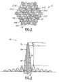
- stratospheric platformsare currently under development.
- One such stratospheric platformis Helios that is being developed by AeroVironment.
- the Helios stratospheric platformis an unmanned vehicle that can fly for several months at a height of about 60,000 feet.
- Heliosis a solar powered electric plane that is modular in design and may be configured to carry a variety of payloads.
- Stratospheric platformshave numerous advantages over geo-stationary satellites, including that a large bandwidth density can be projected over a small but populated area, associated transmission delays are significantly reduced, the power required for transmitting and receiving is substantially smaller, and the user elevation are higher in general. Also, these stratospheric platforms can be deployed relatively rapidly compared to satellites and thus, if a business need increases, the system capability may be increased quickly through deploying new platforms.
- such communication systemshave a high altitude communications device such as a satellite or a stratospheric platform as described above. Also, such systems have user terminals and a gateway station or plurality of gateway stations that communicate with the high altitude communications device and link the user terminals to terrestrial networks.
- CDMAcode division multiple access
- TDMAtime division multiple access
- FDMAfrequency division multiple access
- the user links between the high altitude device and user terminalsoperate at different frequencies, times or codes than those of the feeder link to prevent interference.
- frequency resourcesare scarce, it would be desirable to provide a system that utilizes the same communication frequency spectrum of the user links in the feeder link.
- a communication systemhas a high altitude communication device generating a plurality of user link beams having a first communication characteristic and a feeder link having a first communication characteristic.
- a gateway terminalwith higher gain and narrower beam-width receives not the user link but a feeder link beam with a much higher data throughput rate than those from a user link.
- a user terminalreceives at least one of the user link beams.
- the communications systemfeatures a “spoke-and-hub” (S-&-H) architecture. Connectivity among users is established not directly but through a central hub.
- a platformmay be connected to various users via different user link beams and codes. But there is no cross-beam nor cross-code connectivity on board the platform.
- the platformpipes all the user signals back to a ground hub through a high data rate feeder link.
- the connectivity among user signalsis achieved through switching and/or routing mechanisms on ground.
- the plurality of user link beamscomprises a first user link beam associated a first cell and a first isolation zone outside said first cell.
- the plurality of user link beamscomprises a second user link beam having the first communication characteristic and positioned within a second cell and a second isolation zone outside said second cell.
- the second isolation zoneoverlaps the first isolation zone.
- the feeder linkis positioned within the first isolation zone and the second isolation zone.
- the feeder linkhas the first communication characteristic.
- a method of operating communication systemcomprises the steps of:
- generating a second user link beamhaving a first communication characteristic and a second cell zone and a second isolation zone at least partially overlapping said first isolation zone;
- One advantage of the inventionis that the user link transmission antenna and the feeder link transmission antenna are decoupled to allow independent optimizations on the platform use link and feeder link antenna designs.
- FIG. 1is a system level view of the communication system, according to the present invention.
- FIG. 2is reuse plot of a cell coverage map illustrating cells with various communication characteristics.
- FIG. 3is a view of a communication beam gain pattern according to the present invention.
- FIG. 4is a view of two beam gain patterns of adjacent beams having overlapping isolation zones according to the present invention.
- FIG. 5is a view of the gain pattern of two user links and a feeder link according to the present invention.
- FIG. 6is a partial cell pattern illustrating a plurality of gateway stations in a single cell.
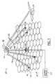
- FIG. 7is a schematic view of a multiple beam antenna system wherein multiple beams from a single platform are connected by multiple gateway stations.
- a communications system 10has a cell pattern 12 that is illustrated as a plurality of hexagons on the earth's surface.
- the hexagonsrepresent the footprint of a radiated beam onto the earth's surface.
- Theseare otherwise known as cells 14 .
- Each cell 14represents a geographic area that can receive signals from the stratospheric platform with a pre-determined signal strength.
- a plurality of user terminals 16are used to illustrate fixed users. Each user terminal 16 may receive a signal with the predetermined signal strength within a spot beam in a multiple spot beam pattern radiated from a communications payload of the high altitude communication device 18 .
- Communication system 10further includes a gateway station 20 that is coupled to terrestrial networks 22 .
- Communication systemmay also include a device operations center 24 . Both gateway station 20 and device operations center 24 are in communication with high altitude communication device 18 .
- Gateway station 20provides connectivity between user terminals 16 and terrestrial networks 22 through high altitude communications device 18 .
- Device operation center 24provides command and control functions to communications device 18 . Although illustrated as two separate units, gateway station 20 and device operation center 24 may be combined into the same physical location.
- the communication signals between high altitude communication device 18 and user terminals 16may be referred to as user links 26 .
- User links 26represent the transmit and receive beams from user device 16 and high altitude communications device 18 .
- a feeder link 28is defined between high altitude communications device 18 and gateway station 20 .
- High altitude communications device 18such as those under development by AeroVironment, Helios, is an unmanned vehicle that can fly for several months at an altitude of about 60,000 feet above the earth.
- Heliosis a solar-powered, electric plane that is modular in design and may be configured in a variety of ways.
- the stratospheric platformis operated through the device operations center 24 to fly in a small radius flight path over a given spot on the earth.
- High altitude communications device 18is used as a communication node for gateway station 20 and user terminals 16 , each of which has a medium gain antenna with a small beam-width that is pointed at the direction of the high altitude communications device 18 .
- gateway station 20has a high gain antenna with very small beam width that may need a tracking mechanism to maintain a communication link with high altitude communication device 18 throughout the flight path. These antennas may be electronically or mechanically steered.
- High altitude communication device 18has a payload 30 that is used to connect user terminals 16 and gateway station 20 .
- the payload 30is used to generate a plurality of beams in a frequency division multiple access system.
- those skilled in the artwould recognize that the present invention is equally applicable to a code division multiple access system.
- Various number of usersmay communicate within a beam.
- FIG. 2a plan view of a cell reuse pattern 12 is illustrated having cells 14 .
- FIG. 2illustrates a FDMA system with four different frequencies illustrated as four differently cross-hatched areas. This is called a four-beam frequency reuse pattern.
- Those skilled in the artwill recognize that various numbers of frequencies may be used, such as three-beam or 7 beam frequency reused pattern.
- the entire frequency spectrumis subdivided into 4 frequency bands, cells 14 A have one frequency band, cells 14 B have a second frequency band, cells 14 C have a third frequency band, and cells 14 D have a fourth frequency band.
- Each cellbelongs to one of either 14 A, 14 B, 14 C or 14 D as symbolized by the different cross-hatching.
- this inventionapplies equally to code in place of frequency band.
- a plurality of gateway stations 20 A, 20 B, 20 C, 20 D and 20 Eare illustrated.
- High altitude communication device 18is located above the cell 32 .
- FIG. 3certain antenna restrictions apply to user terminal antennas, gateway antennas, and platform antennas to enable frequency reuse.
- a typical antenna radiation beam pattern 34is illustrated in FIG. 3 .
- Beam pattern 34has a center portion 36 that corresponds to the gain within the width of a cell 14 . There will be a predetermined power flux density within the center portion 36 .
- the height D 1is referred to as the cell center to edge ratio.
- the central cellwill feature a circular shape.
- the overlapped areais simplified among adjacent beams to make the cell shape hexagonal.
- the area just outside the center portion 36is the isolation zone 38 .
- Isolation zone 38extends a predetermined distance outside the cell 14 .
- the isolation zone 38is the area that extends the distance D 2 from cell 14 . There is an acceptable minimum distance for reusing the same frequency in another location while controlling interference and maintaining an acceptable signal to noise ratio.
- D 1the cell center to edge ratio
- the neighboring cellhas the power flux density steadily decreasing through the isolation zone 38 . Quality reception in the isolation zone and the neighboring cell cannot be insured so that frequency reuse can be performed.
- the gain of the side lobes 40is designed to be about ⁇ 20 to ⁇ 30 dB in general; small enough to not interfere with beams using the same frequency.
- three cells 14 A, 14 B and 14 Care illustrated in a one-dimensional antenna pattern. These three cells are on a same plane as illustrated in FIG. 2 . They are a part of the beam pattern in a triangular lattice. Also depicted in FIG. 4, a first center portion 36 A of a beam pattern 34 A and a second center portion 36 B of a second beam pattern 34 B are illustrated.
- the beam patterns 34 A and 34 Bhave the same communication characteristic (in this example frequency and code).
- Cells 14 A and 14 Bare separated from each other by an angular distance that equals to a cell 14 C.
- signal strengths intended for users in 14 B and 14 Amust decrease sufficiently in the isolation zones so that the frequency may be reused with the spacing of only one cell there between. Consequently, isolation zones 38 A and 38 B overlap.
- Feeder link beam 44has the same communication characteristics such as frequency but has a higher gain and a narrower beam-width than those for user beams as indicated by the center portions 36 A and 36 B.
- feeder link 44is located between center portions 36 A and 36 B.
- the isolation portion 46preferably does not extend beyond the cell 14 C. That is, the isolation portion 46 is coextensive or overlaps the isolation zones 38 A and 38 B.
- the feeder link 44may use the same frequency spectrum of the user link 26 .
- the frequency spectrum for the communication system 10is efficiently utilized not only used and reused by user links but also by feeder links. Because the gateway antenna allows the feeder link 28 to operate at a higher gain, very minimum interference of the adjacent user beams is obtained from the isolation zones 38 A, 38 B.
- FIG. 6a portion of a cell pattern 12 is illustrated. Having various cells 14 .
- four gateway stations 48 A, 48 B, 48 C and 48 Dare positioned in a single cell. These 4 isolated beams are spaced at least 2 beam-widths away from each other. Furthermore there are interference cancellation techniques to assure adequate isolation among the 4 beams.
- Each of the gateway stations 48 A through 48 Duse the same frequency spectrum. This is possible because the gateway stations 48 A through 48 D have a higher gain and little or no interference is achieved between adjacent gateway stations 48 A through 48 D.
- the feeder link antenna apertureis four to five times as large in radius as the user link antenna aperture, the feeder link antenna gain is 12 to 14 dB more than the user link antenna gain.
- the beam width for the feeder linkis at least four to five times narrower than the beam width of the user link. If traffic is uniformly distributed, a gateway station can use 75% of the total band for its feeder link transmission. For a seven frequency reuse pattern, a gateway station can use about 85% of the total band width. Preferably, gateway stations should be located in cells with relatively less traffic such that the user-link frequency band width is less than average.
- a cell pattern 12is illustrated with three gateway stations 52 A, 52 B and 52 C. As illustrated, gateway stations 52 A, 52 B are positioned in the same cell while station 52 C is in the adjacent cell. 52 A & 52 B can use the same portion of the frequency spectrum and 52 C could use a different portion of the spectrum.
- a high altitude communication device 18is illustrated having an antenna reflector 54 with multiple feed horns 54 A, 54 B and 54 C. Each feed horn 54 A through 54 C may service different gateway stations 52 A through 52 C. That is, feed horns 54 A through 54 C preferably serve a respective gateway station 52 A through 52 C.
- the feed hornsare spaced properly so that the “images of the feeds” (or beams) illuminate the corresponding gateway stations.
- the positions among the feed horns and the reflector focusdetermines the relevant directions and distance of the two gateway stations on the ground. If n gateway stations are needed for the platform system, then the platform antenna should have n feed horns.
Landscapes
- Engineering & Computer Science (AREA)
- Computer Networks & Wireless Communication (AREA)
- Signal Processing (AREA)
- Physics & Mathematics (AREA)
- Astronomy & Astrophysics (AREA)
- Aviation & Aerospace Engineering (AREA)
- General Physics & Mathematics (AREA)
- Mobile Radio Communication Systems (AREA)
- Radio Relay Systems (AREA)
Abstract
Description
Claims (21)
Priority Applications (1)
| Application Number | Priority Date | Filing Date | Title |
|---|---|---|---|
| US09/612,465US6751458B1 (en) | 2000-07-07 | 2000-07-07 | Architecture utilizing frequency reuse in accommodating user-link and feeder-link transmissions |
Applications Claiming Priority (1)
| Application Number | Priority Date | Filing Date | Title |
|---|---|---|---|
| US09/612,465US6751458B1 (en) | 2000-07-07 | 2000-07-07 | Architecture utilizing frequency reuse in accommodating user-link and feeder-link transmissions |
Publications (1)
| Publication Number | Publication Date |
|---|---|
| US6751458B1true US6751458B1 (en) | 2004-06-15 |
Family
ID=32393749
Family Applications (1)
| Application Number | Title | Priority Date | Filing Date |
|---|---|---|---|
| US09/612,465Expired - LifetimeUS6751458B1 (en) | 2000-07-07 | 2000-07-07 | Architecture utilizing frequency reuse in accommodating user-link and feeder-link transmissions |
Country Status (1)
| Country | Link |
|---|---|
| US (1) | US6751458B1 (en) |
Cited By (10)
| Publication number | Priority date | Publication date | Assignee | Title |
|---|---|---|---|---|
| US20030224723A1 (en)* | 2002-05-30 | 2003-12-04 | Feng-Wen Sun | Method and system for providing two-way communication using an overlay of signals over a non-linear communications channel |
| US20040198346A1 (en)* | 2003-04-02 | 2004-10-07 | The Boeing Company | Aircraft based cellular system |
| US20080146145A1 (en)* | 2006-12-14 | 2008-06-19 | Viasat, Inc. | Satellite communication system and method with asymmetric feeder and service frequency bands |
| US20090081946A1 (en)* | 2006-09-26 | 2009-03-26 | Viasat, Inc. | Placement of Gateways Away from Service Beams |
| US20090298416A1 (en)* | 2006-09-26 | 2009-12-03 | Viasat, Inc. | Satellite Architecture |
| US20110007686A1 (en)* | 2007-04-13 | 2011-01-13 | Space Systems/Loral, Inc. | Multi-beam satellite network to maximize bandwidth utilization |
| US20150188623A1 (en)* | 2012-06-29 | 2015-07-02 | Agence Spatiale Europeenne | Multibeam Satellite Communication System and Method, and Satellite Payload for Carrying Out Such a Method |
| US9236934B1 (en) | 2009-10-16 | 2016-01-12 | Viasat, Inc. | Satellite system architecture for coverage areas of disparate demand |
| US10103812B2 (en) | 2016-01-27 | 2018-10-16 | The Boeing Company | Satellite communication system |
| US20250249997A1 (en)* | 2021-04-08 | 2025-08-07 | Space Balloon Technologies Corp. | Apparatus, Method And System For Balloon Altitude Control By In-Situ Characterization And Active Energy Management |
Citations (35)
| Publication number | Priority date | Publication date | Assignee | Title |
|---|---|---|---|---|
| US4819227A (en) | 1986-08-14 | 1989-04-04 | Hughes Aircraft Company | Satellite communications system employing frequency reuse |
| WO1990013186A1 (en) | 1989-04-25 | 1990-11-01 | Geostar Corporation | Communication system employing multiple relay satellites operating on common downlink frequency |
| US5077562A (en) | 1990-12-24 | 1991-12-31 | Hughes Aircraft Company | Digital beam-forming technique using temporary noise injection |
| EP0549220A2 (en) | 1991-12-23 | 1993-06-30 | Motorola, Inc. | Satellite system cell management |
| US5555257A (en) | 1994-01-11 | 1996-09-10 | Ericsson Ge Mobile Communications Inc. | Cellular/satellite communications system with improved frequency re-use |
| WO1996031016A1 (en) | 1995-03-29 | 1996-10-03 | International Mobile Satellite Organization | Method and apparatus for limiting interference between satellite systems |
| US5572216A (en) | 1993-11-19 | 1996-11-05 | Stanford Telecommunications, Inc. | System for increasing the utility of satellite communication systems |
| WO1997007609A2 (en) | 1995-08-11 | 1997-02-27 | Ramot University Authority For Applied Research & Industrial Development Ltd. | High altitude cellular communication system platform |
| US5612701A (en) | 1995-09-18 | 1997-03-18 | Motorola, Inc. | Adaptive beam pointing method and apparatus for a communication system |
| EP0845874A2 (en) | 1996-12-02 | 1998-06-03 | TRW Inc. | Geolocation method and apparatus for satellite based telecommunications systems |
| US5790070A (en) | 1997-05-05 | 1998-08-04 | Motorola, Inc. | Network and method for controlling steerable beams |
| US5839053A (en) | 1995-08-02 | 1998-11-17 | Agence Spatiale Europeene | System for transmitting radio signals from mobile terminals to provide space diversity for uplink signals via geostationary communication satellites |
| WO1998051568A1 (en) | 1997-05-16 | 1998-11-19 | Spherecore, Inc. | Aerial communications network |
| US5856804A (en) | 1996-10-30 | 1999-01-05 | Motorola, Inc. | Method and intelligent digital beam forming system with improved signal quality communications |
| WO1999013598A1 (en) | 1997-09-08 | 1999-03-18 | Angel Technologies Corporation | Wireless communication using atmospheric platform |
| US5903549A (en) | 1997-02-21 | 1999-05-11 | Hughes Electronics Corporation | Ground based beam forming utilizing synchronized code division multiplexing |
| WO1999023769A1 (en) | 1997-10-30 | 1999-05-14 | Raytheon Company | Wireless communication using an airborne switching node |
| US5949766A (en) | 1996-12-30 | 1999-09-07 | Motorola, Inc. | Ground device for communicating with an elevated communication hub and method of operation thereof |
| US5974317A (en) | 1996-11-08 | 1999-10-26 | Lucent Technologies, Inc. | Cell-clustering arrangements and corresponding antenna patterns for wireless communication networks employing high-altitude aeronautical antenna platforms |
| US6018316A (en) | 1997-01-24 | 2000-01-25 | Ail Systems, Inc. | Multiple beam antenna system and method |
| US6020845A (en) | 1993-11-19 | 2000-02-01 | Stanford Telecommunications, Inc. | Satellite for increasing the utility of satellite communication systems |
| US6111542A (en) | 1998-04-06 | 2000-08-29 | Motorola, Inc. | Rotating electronically steerable antenna system and method of operation thereof |
| GB2349045A (en) | 1999-04-16 | 2000-10-18 | Fujitsu Ltd | Base station transmission beam pattern forming; interference reduction |
| US6138012A (en) | 1997-08-04 | 2000-10-24 | Motorola, Inc. | Method and apparatus for reducing signal blocking in a satellite communication system |
| US6147658A (en) | 1998-07-06 | 2000-11-14 | Murata Manufacturing Co., Ltd. | Array antenna device and radio equipment |
| US6151308A (en) | 1996-12-30 | 2000-11-21 | Motorola, Inc. | Elevated communication hub and method of operation therefor |
| US6173178B1 (en) | 1997-12-16 | 2001-01-09 | Trw Inc. | Satellite beam pattern for non-uniform population distribution |
| US6205320B1 (en) | 1998-09-04 | 2001-03-20 | Richard Coleman | System for satellite to airship to gateway/customer premise equipment, and airship to airship, high data rate relay |
| US6208626B1 (en)* | 1998-12-24 | 2001-03-27 | Charles R. Brewer | Real-time satellite communication system using separate control and data transmission paths |
| US6215776B1 (en)* | 1997-10-08 | 2001-04-10 | Lockheed Martin Missiles & Space Company | Satellite communication system |
| US6236834B1 (en) | 1993-12-15 | 2001-05-22 | International Mobile Satellite Organization | Method and apparatus for limiting interference between satellite systems |
| US6317420B1 (en)* | 1999-06-25 | 2001-11-13 | Qualcomm Inc. | Feeder link spatial multiplexing in a satellite communication system |
| US6324398B1 (en) | 1996-02-26 | 2001-11-27 | Lucent Technologies Inc. | Wireless telecommunications system having airborne base station |
| US20020006795A1 (en) | 1997-10-17 | 2002-01-17 | Norin John L. | Non-uniform multi-beam satellite communications method |
| US6388615B1 (en) | 2000-06-06 | 2002-05-14 | Hughes Electronics Corporation | Micro cell architecture for mobile user tracking communication system |
- 2000
- 2000-07-07USUS09/612,465patent/US6751458B1/ennot_activeExpired - Lifetime
Patent Citations (38)
| Publication number | Priority date | Publication date | Assignee | Title |
|---|---|---|---|---|
| US4819227A (en) | 1986-08-14 | 1989-04-04 | Hughes Aircraft Company | Satellite communications system employing frequency reuse |
| WO1990013186A1 (en) | 1989-04-25 | 1990-11-01 | Geostar Corporation | Communication system employing multiple relay satellites operating on common downlink frequency |
| US5077562A (en) | 1990-12-24 | 1991-12-31 | Hughes Aircraft Company | Digital beam-forming technique using temporary noise injection |
| EP0549220A2 (en) | 1991-12-23 | 1993-06-30 | Motorola, Inc. | Satellite system cell management |
| US5572216A (en) | 1993-11-19 | 1996-11-05 | Stanford Telecommunications, Inc. | System for increasing the utility of satellite communication systems |
| US6020845A (en) | 1993-11-19 | 2000-02-01 | Stanford Telecommunications, Inc. | Satellite for increasing the utility of satellite communication systems |
| US6236834B1 (en) | 1993-12-15 | 2001-05-22 | International Mobile Satellite Organization | Method and apparatus for limiting interference between satellite systems |
| US5555257A (en) | 1994-01-11 | 1996-09-10 | Ericsson Ge Mobile Communications Inc. | Cellular/satellite communications system with improved frequency re-use |
| US5594941A (en) | 1994-01-11 | 1997-01-14 | Ericsson Inc. | A cellular/satellite communications system with generation of a plurality of sets of intersecting antenna beams |
| WO1996031016A1 (en) | 1995-03-29 | 1996-10-03 | International Mobile Satellite Organization | Method and apparatus for limiting interference between satellite systems |
| US5839053A (en) | 1995-08-02 | 1998-11-17 | Agence Spatiale Europeene | System for transmitting radio signals from mobile terminals to provide space diversity for uplink signals via geostationary communication satellites |
| WO1997007609A2 (en) | 1995-08-11 | 1997-02-27 | Ramot University Authority For Applied Research & Industrial Development Ltd. | High altitude cellular communication system platform |
| US5612701A (en) | 1995-09-18 | 1997-03-18 | Motorola, Inc. | Adaptive beam pointing method and apparatus for a communication system |
| US6324398B1 (en) | 1996-02-26 | 2001-11-27 | Lucent Technologies Inc. | Wireless telecommunications system having airborne base station |
| US5856804A (en) | 1996-10-30 | 1999-01-05 | Motorola, Inc. | Method and intelligent digital beam forming system with improved signal quality communications |
| US5974317A (en) | 1996-11-08 | 1999-10-26 | Lucent Technologies, Inc. | Cell-clustering arrangements and corresponding antenna patterns for wireless communication networks employing high-altitude aeronautical antenna platforms |
| EP0845874A2 (en) | 1996-12-02 | 1998-06-03 | TRW Inc. | Geolocation method and apparatus for satellite based telecommunications systems |
| US5949766A (en) | 1996-12-30 | 1999-09-07 | Motorola, Inc. | Ground device for communicating with an elevated communication hub and method of operation thereof |
| US6151308A (en) | 1996-12-30 | 2000-11-21 | Motorola, Inc. | Elevated communication hub and method of operation therefor |
| US6018316A (en) | 1997-01-24 | 2000-01-25 | Ail Systems, Inc. | Multiple beam antenna system and method |
| US5903549A (en) | 1997-02-21 | 1999-05-11 | Hughes Electronics Corporation | Ground based beam forming utilizing synchronized code division multiplexing |
| US5790070A (en) | 1997-05-05 | 1998-08-04 | Motorola, Inc. | Network and method for controlling steerable beams |
| WO1998051568A1 (en) | 1997-05-16 | 1998-11-19 | Spherecore, Inc. | Aerial communications network |
| US6167263A (en) | 1997-05-16 | 2000-12-26 | Spherecore, Inc. | Aerial communications network including a plurality of aerial platforms |
| US6138012A (en) | 1997-08-04 | 2000-10-24 | Motorola, Inc. | Method and apparatus for reducing signal blocking in a satellite communication system |
| WO1999013598A1 (en) | 1997-09-08 | 1999-03-18 | Angel Technologies Corporation | Wireless communication using atmospheric platform |
| US6215776B1 (en)* | 1997-10-08 | 2001-04-10 | Lockheed Martin Missiles & Space Company | Satellite communication system |
| US20020006795A1 (en) | 1997-10-17 | 2002-01-17 | Norin John L. | Non-uniform multi-beam satellite communications method |
| US6061562A (en) | 1997-10-30 | 2000-05-09 | Raytheon Company | Wireless communication using an airborne switching node |
| WO1999023769A1 (en) | 1997-10-30 | 1999-05-14 | Raytheon Company | Wireless communication using an airborne switching node |
| US6173178B1 (en) | 1997-12-16 | 2001-01-09 | Trw Inc. | Satellite beam pattern for non-uniform population distribution |
| US6111542A (en) | 1998-04-06 | 2000-08-29 | Motorola, Inc. | Rotating electronically steerable antenna system and method of operation thereof |
| US6147658A (en) | 1998-07-06 | 2000-11-14 | Murata Manufacturing Co., Ltd. | Array antenna device and radio equipment |
| US6205320B1 (en) | 1998-09-04 | 2001-03-20 | Richard Coleman | System for satellite to airship to gateway/customer premise equipment, and airship to airship, high data rate relay |
| US6208626B1 (en)* | 1998-12-24 | 2001-03-27 | Charles R. Brewer | Real-time satellite communication system using separate control and data transmission paths |
| GB2349045A (en) | 1999-04-16 | 2000-10-18 | Fujitsu Ltd | Base station transmission beam pattern forming; interference reduction |
| US6317420B1 (en)* | 1999-06-25 | 2001-11-13 | Qualcomm Inc. | Feeder link spatial multiplexing in a satellite communication system |
| US6388615B1 (en) | 2000-06-06 | 2002-05-14 | Hughes Electronics Corporation | Micro cell architecture for mobile user tracking communication system |
Non-Patent Citations (10)
| Title |
|---|
| Colella N J et al., "The HALO Network (TM)", IEEE Communications Magazine, IEEE Service Center, Piscataway, N.J. U.S., vol. 38, No. 6, Jun. 2000, pp. 142-148, XP 000932657, ISSN: 0163-6804. |
| Colella N J et al., "The HALO Network ™", IEEE Communications Magazine, IEEE Service Center, Piscataway, N.J. U.S., vol. 38, No. 6, Jun. 2000, pp. 142-148, XP 000932657, ISSN: 0163-6804. |
| Colella, Nocholas J. et al., "High-Speed Internet Access via Stratospheric HALO Aircraft", INET'99 Proceedings, http://www.isoc.org/conferences/inet/99/proceedings/index.htm, 4. Technology, Wireless, Jun. 8, 1999. |
| K. K. Chan, et al., "A Circularly Polarized Waveguide Array for Leo Satellite Communications", Antennas and Propagation Society, 1999, IEEE International Symposium, vol. 1 Jul. 11-16, 1999, pp. 154-157. |
| M. Oodo, et al, "Onboard DBF Antenna for Stratospheric Platform", 2000 IEEE International Conference on Phased Array Systems and Technology, Proceedings, May 21-25, 2000, pp. 125-128. |
| R. Suzuki et al., "Mobile TDM/IDMA System with Active Array Antenna", Global Telecommunications Conference, 1991, GLOBECOM '91; Dec. 2-5, 1991; pp. 1569-1573, vol. 3. |
| U.S. patent application Ser. No. 09/594,374, Chang et al., filed Jun. 15, 2000. |
| U.S. patent application Ser. No. 09/594,375, Chang et al., filed Jun. 15, 2000. |
| U.S. patent application Ser. No. 09/649,355, Hagen et al., filed Aug. 28, 2000. |
| U.S. patent application Ser. No. 09/718,973, Wang et al., filed Nov. 21, 2000. |
Cited By (27)
| Publication number | Priority date | Publication date | Assignee | Title |
|---|---|---|---|---|
| US20030224723A1 (en)* | 2002-05-30 | 2003-12-04 | Feng-Wen Sun | Method and system for providing two-way communication using an overlay of signals over a non-linear communications channel |
| US7715838B2 (en)* | 2003-04-02 | 2010-05-11 | The Boeing Company | Aircraft based cellular system |
| US20040198346A1 (en)* | 2003-04-02 | 2004-10-07 | The Boeing Company | Aircraft based cellular system |
| US8538323B2 (en) | 2006-09-26 | 2013-09-17 | Viasat, Inc. | Satellite architecture |
| EP2645597B1 (en) | 2006-09-26 | 2016-11-16 | ViaSat, Inc. | Improved spot beam satellite systems |
| US20090291633A1 (en)* | 2006-09-26 | 2009-11-26 | Viasat, Inc. | Frequency re-use for service and gateway beams |
| US20090298416A1 (en)* | 2006-09-26 | 2009-12-03 | Viasat, Inc. | Satellite Architecture |
| US20090081946A1 (en)* | 2006-09-26 | 2009-03-26 | Viasat, Inc. | Placement of Gateways Away from Service Beams |
| EP2645597B2 (en)† | 2006-09-26 | 2024-03-06 | ViaSat, Inc. | Improved spot beam satellite systems |
| EP2645596B1 (en) | 2006-09-26 | 2016-12-21 | ViaSat, Inc. | Improved spot beam satellite systems |
| US8254832B2 (en) | 2006-09-26 | 2012-08-28 | Viasat, Inc. | Frequency re-use for service and gateway beams |
| US8315199B2 (en) | 2006-09-26 | 2012-11-20 | Viasat, Inc. | Adaptive use of satellite uplink bands |
| US20090290530A1 (en)* | 2006-09-26 | 2009-11-26 | Viasat, Inc. | Adaptive use of satellite uplink bands |
| US8548377B2 (en) | 2006-09-26 | 2013-10-01 | Viasat, Inc. | Frequency re-use for service and gateway beams |
| US8855552B2 (en) | 2006-09-26 | 2014-10-07 | Viasat, Inc. | Placement of gateways away from service beams |
| US9172457B2 (en) | 2006-09-26 | 2015-10-27 | Viasat, Inc. | Frequency re-use for service and gateway beams |
| US20080146145A1 (en)* | 2006-12-14 | 2008-06-19 | Viasat, Inc. | Satellite communication system and method with asymmetric feeder and service frequency bands |
| US7869759B2 (en) | 2006-12-14 | 2011-01-11 | Viasat, Inc. | Satellite communication system and method with asymmetric feeder and service frequency bands |
| US20110007686A1 (en)* | 2007-04-13 | 2011-01-13 | Space Systems/Loral, Inc. | Multi-beam satellite network to maximize bandwidth utilization |
| US9236934B1 (en) | 2009-10-16 | 2016-01-12 | Viasat, Inc. | Satellite system architecture for coverage areas of disparate demand |
| US9654203B2 (en) | 2009-10-16 | 2017-05-16 | Viasat, Inc. | Satellite system architecture for coverage areas of disparate demand |
| US10305579B2 (en) | 2009-10-16 | 2019-05-28 | Viasat, Inc. | Satellite system architecture for coverage areas of disparate demand |
| US10727933B2 (en) | 2009-10-16 | 2020-07-28 | Viasat, Inc. | Satellite system architecture for coverage areas of disparate demand |
| US20150188623A1 (en)* | 2012-06-29 | 2015-07-02 | Agence Spatiale Europeenne | Multibeam Satellite Communication System and Method, and Satellite Payload for Carrying Out Such a Method |
| US9356685B2 (en)* | 2012-06-29 | 2016-05-31 | Agence Spatiale Europeenne | Multibeam satellite communication system and method, and satellite payload for carrying out such a method |
| US10103812B2 (en) | 2016-01-27 | 2018-10-16 | The Boeing Company | Satellite communication system |
| US20250249997A1 (en)* | 2021-04-08 | 2025-08-07 | Space Balloon Technologies Corp. | Apparatus, Method And System For Balloon Altitude Control By In-Situ Characterization And Active Energy Management |
Similar Documents
| Publication | Publication Date | Title |
|---|---|---|
| EP1224752B1 (en) | Stratospheric platforms based mobile communications architecture | |
| EP1230748B1 (en) | Micro cell architecture for mobile user tracking in a communication system | |
| US6336030B2 (en) | Method and system for providing satellite coverage using fixed spot beams and scanned spot beams | |
| US7024158B2 (en) | Broadband communication satellite | |
| EP0910180B1 (en) | Non-uniform multi-beam satellite communications system and method | |
| EP1062747B1 (en) | Method and apparatus for providing wideband services using medium and low earth orbit satellites | |
| US4819227A (en) | Satellite communications system employing frequency reuse | |
| US7027769B1 (en) | GEO stationary communications system with minimal delay | |
| US7382743B1 (en) | Multiple-beam antenna system using hybrid frequency-reuse scheme | |
| JPH021629A (en) | Common frequency type satellite communication system | |
| US12388523B2 (en) | Techniques for switching between operating modes of beamforming systems and satellites | |
| US8103270B2 (en) | Fixed cell communication system with reduced interference | |
| US7200360B1 (en) | Communication system as a secondary platform with frequency reuse | |
| US20120075149A1 (en) | Multi-beam telecommunication antenna onboard a high-capacity satellite and related telecommunication system | |
| WO2007047159A2 (en) | Satellites and signal distribution methods and off-set pattern for sending signals | |
| JPH0728175B2 (en) | Hybrid communication satellite antenna system | |
| JPH04233804A (en) | Method and apparatus for generating stacked scanning beam enabling execution of frequency address | |
| US6751458B1 (en) | Architecture utilizing frequency reuse in accommodating user-link and feeder-link transmissions | |
| EP1230740A2 (en) | Satellite communication system having frequency reuse in non-blocking manner |
Legal Events
| Date | Code | Title | Description |
|---|---|---|---|
| AS | Assignment | Owner name:HUGHES ELECTRONICS CORPORATION, CALIFORNIA Free format text:ASSIGNMENT OF ASSIGNORS INTEREST;ASSIGNORS:WANG, WEIZHENG;CHANG, DONALD C.D.;CHANG, MING U.;AND OTHERS;REEL/FRAME:010997/0117;SIGNING DATES FROM 20000626 TO 20000706 | |
| STCF | Information on status: patent grant | Free format text:PATENTED CASE | |
| FPAY | Fee payment | Year of fee payment:4 | |
| REMI | Maintenance fee reminder mailed | ||
| FPAY | Fee payment | Year of fee payment:8 | |
| FPAY | Fee payment | Year of fee payment:12 | |
| AS | Assignment | Owner name:THE DIRECTV GROUP, INC., CALIFORNIA Free format text:MERGER AND CHANGE OF NAME;ASSIGNORS:HUGHES ELECTRONICS CORPORATION;THE DIRECTV GROUP, INC.;REEL/FRAME:056984/0334 Effective date:20040316 | |
| AS | Assignment | Owner name:DIRECTV, LLC, CALIFORNIA Free format text:ASSIGNMENT OF ASSIGNORS INTEREST;ASSIGNOR:THE DIRECTV GROUP, INC.;REEL/FRAME:057020/0035 Effective date:20210728 | |
| AS | Assignment | Owner name:CREDIT SUISSE AG, CAYMAN ISLANDS BRANCH, AS COLLATERAL AGENT, NEW YORK Free format text:SECURITY AGREEMENT;ASSIGNOR:DIRECTV, LLC;REEL/FRAME:057695/0084 Effective date:20210802 | |
| AS | Assignment | Owner name:THE BANK OF NEW YORK MELLON TRUST COMPANY, N.A. AS COLLATERAL AGENT, TEXAS Free format text:SECURITY AGREEMENT;ASSIGNOR:DIRECTV, LLC;REEL/FRAME:058220/0531 Effective date:20210802 |