US6749627B2 - Grip for stent delivery system - Google Patents
Grip for stent delivery systemDownload PDFInfo
- Publication number
- US6749627B2 US6749627B2US09/765,721US76572101AUS6749627B2US 6749627 B2US6749627 B2US 6749627B2US 76572101 AUS76572101 AUS 76572101AUS 6749627 B2US6749627 B2US 6749627B2
- Authority
- US
- United States
- Prior art keywords
- tubular member
- outer tubular
- sides
- handle
- delivery system
- Prior art date
- Legal status (The legal status is an assumption and is not a legal conclusion. Google has not performed a legal analysis and makes no representation as to the accuracy of the status listed.)
- Expired - Lifetime, expires
Links
- 125000006850spacer groupChemical group0.000claimsdescription8
- 230000004323axial lengthEffects0.000claimsdescription5
- 238000004891communicationMethods0.000claimsdescription3
- 229910000831SteelInorganic materials0.000claims1
- 239000010959steelSubstances0.000claims1
- 239000010935stainless steelSubstances0.000description14
- 229910001220stainless steelInorganic materials0.000description14
- 239000002872contrast mediaSubstances0.000description11
- 229940039231contrast mediaDrugs0.000description11
- 238000010276constructionMethods0.000description6
- 238000002594fluoroscopyMethods0.000description4
- 238000013461designMethods0.000description3
- 229910052751metalInorganic materials0.000description3
- 239000002184metalSubstances0.000description3
- 239000012530fluidSubstances0.000description2
- 239000000463materialSubstances0.000description2
- 238000000034methodMethods0.000description2
- 229910001000nickel titaniumInorganic materials0.000description2
- HLXZNVUGXRDIFK-UHFFFAOYSA-Nnickel titaniumChemical compound[Ti].[Ti].[Ti].[Ti].[Ti].[Ti].[Ti].[Ti].[Ti].[Ti].[Ti].[Ni].[Ni].[Ni].[Ni].[Ni].[Ni].[Ni].[Ni].[Ni].[Ni].[Ni].[Ni].[Ni].[Ni]HLXZNVUGXRDIFK-UHFFFAOYSA-N0.000description2
- 229920000728polyesterPolymers0.000description2
- 238000012800visualizationMethods0.000description2
- 239000004677NylonSubstances0.000description1
- 239000000853adhesiveSubstances0.000description1
- 230000001070adhesive effectEffects0.000description1
- 210000004204blood vesselAnatomy0.000description1
- 210000004351coronary vesselAnatomy0.000description1
- 229920001971elastomerPolymers0.000description1
- 239000000806elastomerSubstances0.000description1
- 208000014674injuryDiseases0.000description1
- 230000002452interceptive effectEffects0.000description1
- 238000002955isolationMethods0.000description1
- 230000009191jumpingEffects0.000description1
- 239000007788liquidSubstances0.000description1
- 238000004519manufacturing processMethods0.000description1
- 239000003550markerSubstances0.000description1
- 150000002739metalsChemical class0.000description1
- 238000012986modificationMethods0.000description1
- 230000004048modificationEffects0.000description1
- 239000002991molded plasticSubstances0.000description1
- 229920001778nylonPolymers0.000description1
- -1polybutylene terephthalatePolymers0.000description1
- 229920001707polybutylene terephthalatePolymers0.000description1
- 230000002028prematureEffects0.000description1
- 239000012858resilient materialSubstances0.000description1
- 238000007789sealingMethods0.000description1
- 229910001285shape-memory alloyInorganic materials0.000description1
- 230000007704transitionEffects0.000description1
- 230000008733traumaEffects0.000description1
- 230000000007visual effectEffects0.000description1
Images


Classifications
- A—HUMAN NECESSITIES
- A61—MEDICAL OR VETERINARY SCIENCE; HYGIENE
- A61F—FILTERS IMPLANTABLE INTO BLOOD VESSELS; PROSTHESES; DEVICES PROVIDING PATENCY TO, OR PREVENTING COLLAPSING OF, TUBULAR STRUCTURES OF THE BODY, e.g. STENTS; ORTHOPAEDIC, NURSING OR CONTRACEPTIVE DEVICES; FOMENTATION; TREATMENT OR PROTECTION OF EYES OR EARS; BANDAGES, DRESSINGS OR ABSORBENT PADS; FIRST-AID KITS
- A61F2/00—Filters implantable into blood vessels; Prostheses, i.e. artificial substitutes or replacements for parts of the body; Appliances for connecting them with the body; Devices providing patency to, or preventing collapsing of, tubular structures of the body, e.g. stents
- A61F2/95—Instruments specially adapted for placement or removal of stents or stent-grafts
- A—HUMAN NECESSITIES
- A61—MEDICAL OR VETERINARY SCIENCE; HYGIENE
- A61B—DIAGNOSIS; SURGERY; IDENTIFICATION
- A61B17/00—Surgical instruments, devices or methods
- A61B17/28—Surgical forceps
- A61B17/29—Forceps for use in minimally invasive surgery
- A61B17/2909—Handles
- A—HUMAN NECESSITIES
- A61—MEDICAL OR VETERINARY SCIENCE; HYGIENE
- A61F—FILTERS IMPLANTABLE INTO BLOOD VESSELS; PROSTHESES; DEVICES PROVIDING PATENCY TO, OR PREVENTING COLLAPSING OF, TUBULAR STRUCTURES OF THE BODY, e.g. STENTS; ORTHOPAEDIC, NURSING OR CONTRACEPTIVE DEVICES; FOMENTATION; TREATMENT OR PROTECTION OF EYES OR EARS; BANDAGES, DRESSINGS OR ABSORBENT PADS; FIRST-AID KITS
- A61F2/00—Filters implantable into blood vessels; Prostheses, i.e. artificial substitutes or replacements for parts of the body; Appliances for connecting them with the body; Devices providing patency to, or preventing collapsing of, tubular structures of the body, e.g. stents
- A61F2/95—Instruments specially adapted for placement or removal of stents or stent-grafts
- A61F2/9517—Instruments specially adapted for placement or removal of stents or stent-grafts handle assemblies therefor
- A—HUMAN NECESSITIES
- A61—MEDICAL OR VETERINARY SCIENCE; HYGIENE
- A61M—DEVICES FOR INTRODUCING MEDIA INTO, OR ONTO, THE BODY; DEVICES FOR TRANSDUCING BODY MEDIA OR FOR TAKING MEDIA FROM THE BODY; DEVICES FOR PRODUCING OR ENDING SLEEP OR STUPOR
- A61M25/00—Catheters; Hollow probes
- A61M25/01—Introducing, guiding, advancing, emplacing or holding catheters
- A61M25/09—Guide wires
- A61M2025/09116—Design of handles or shafts or gripping surfaces thereof for manipulating guide wires
- A—HUMAN NECESSITIES
- A61—MEDICAL OR VETERINARY SCIENCE; HYGIENE
- A61M—DEVICES FOR INTRODUCING MEDIA INTO, OR ONTO, THE BODY; DEVICES FOR TRANSDUCING BODY MEDIA OR FOR TAKING MEDIA FROM THE BODY; DEVICES FOR PRODUCING OR ENDING SLEEP OR STUPOR
- A61M25/00—Catheters; Hollow probes
- A61M25/01—Introducing, guiding, advancing, emplacing or holding catheters
- A61M25/09—Guide wires
- A61M2025/09125—Device for locking a guide wire in a fixed position with respect to the catheter or the human body
Definitions
- This inventionpertains to a system for delivering a stent to a site in a body lumen. More particularly, this invention pertains to a stent delivery system with an improved handle construction for manipulation by an operator.
- Stentsare widely used for supporting a lumen structure in a patient's body.
- stentsmay be used to maintain patency of a coronary artery, other blood vessel or other body lumen.
- stentsare commonly metal, tubular structures. Stents are passed through the body lumen in a collapsed state. At the point of an obstruction or other deployment site in the body lumen, the stent is expanded to an expanded diameter to support the lumen at the deployment site.
- stentsare open-celled tubes which are expanded by inflatable balloons at the deployment site.
- Other stentsare so-called “self-expanding” stents.
- Self-expanding stentsdo not use balloons or other application of force to a collapsed stent to cause the expansion of the stent.
- An example of a self-expanding stentis a coil structure which is secured to a stent delivery device under tension in a collapsed state. At the deployment site, the coil is released so that the coil can expand to its enlarged diameter.
- Other self-expanding stentsare made of so-called shape-memory metals such as nitinol. Such shape-memory stents experience a phase change at the elevated temperature of the human body. The phase change results in expansion from a collapsed state to an enlarged state.
- a delivery technique for shape-memory alloy stentsis to mount the collapsed stent on a distal end of a stent delivery system.
- a stent delivery systemSuch a system would include an outer tubular member and an inner tubular member.
- the inner and outer tubular membersare axially slideable relative to one another.
- the stent (in the collapsed state)is mounted surrounding the inner tubular member at its distal end.
- the outer tubular memberalso called the outer sheath
- a guide wirePrior to advancing the stent delivery system through the body lumen, a guide wire is first passed through the body lumen to the deployment site.
- the inner tube of the delivery systemis hollow throughout its length such that it can be advanced over the guide wire to the deployment site.
- the combined structurei.e., stent mounted on stent delivery system
- the deployment systemmay include radio-opaque markers to permit a physician to visualize positioning of the stent prior under fluoroscopy to deployment.
- the outer sheathis retracted to expose the stent.
- the exposed stentis now free to expand within the body lumen.
- the inner tubeis free to pass through the stent such that the delivery system can be removed through the body lumen leaving the stent in place at the deployment site.
- a contrast mediaa liquid which can be visualized under fluoroscopy.
- the contrast mediais injected into the space defined between opposing surfaces of the inner and outer tubes.
- the outer tubehas side ports extending through the sidewall of the outer tube near its distal end. The contrast media is injected into the body lumen through the side ports.
- Prior art stent delivery systemsuse inner and outer tubes of generally uniform diameters and circular cross-section throughout their length. This design relies upon the dynamics of fluid flow to retain spacing between the tubes.
- the inner tubecould bend relative to the outer tube such that surfaces of the inner tube abut surfaces of the outer tube.
- axial forces applied to advance the stent delivery systemcould be stored in the bent inner tube.
- Such energycould be suddenly released with sudden and undesired rapid advance or retraction of the distal tip of the tubes when the inner tube straighten.
- contact between the surfaces of the inner and outer tubes memberscan result in friction between the members resisting relative moment between the tubes.
- a stent deployment systemfor delivering a stent to a deployment site in a body lumen of a patient.
- the stent delivery systemcomprises inner and outer tubular members with the outer tubular member sized to pass through the body lumen to the deployment site and with the inner tubular member sized to be received within the outer tubular member.
- the inner and outer tubular membersare axially slideable relative to one another between a transport position and a deploy position.
- the inner tubular memberhas a stent attachment location at its distal end.
- the stent attachment locationis covered by the outer tubular member when the inner and outer tubular members are in the transport position.
- the stent attachment locationis exposed when the inner and outer tubular members are in the deploy position.
- a first handleis provided rotatably connected to a proximal end of the outer tubular member for the first handle to transmit to the outer tubular member axial forces applied to the handle by an operator and to rotate freely about the axis relative to the outer tubular member.
- the present inventionalso relates to a handle for a medical device delivery system that includes enhanced ergonomic features.
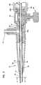
- FIG. 1is a side elevation view of a stent delivery system according to the present invention
- FIG. 2is a side sectional view of a distal end of the stent delivery system of FIG. 1, shown in FIG. 1 as Detail A;
- FIG. 3is a side sectional view of a proximal end of the stent delivery system of FIG. 1, shown in FIG. 1 as Detail B;
- FIG. 4is a sectional view of a second handle of the stent delivery system of FIG. 1 and showing, in section, a guide wire port, shown in FIG. 1 as Detail C;
- FIG. 5is a cross-sectional view of the inner and outer tubular members of the stent delivery system of FIG. 1 taken along lines 5 — 5 of FIG. 3;
- FIG. 6is a perspective view of one-half of a handle of the stent delivery system of FIG. 1 with the opposite half being of identical construction;
- FIG. 7Ais a perspective view of one of the handles of the stent delivery system of FIG. 1;
- FIG. 7Bis a front end view of the handle of FIG. 7A;
- FIG. 7Cis a back end view of the handle of FIG. 7A;
- FIG. 7Dis a front side view of the handle of FIG. 7A;
- FIG. 7Eis a back side view of the handle of FIG. 7A;
- FIG. 7Fis a top view of the handle of FIG. 7A.
- FIG. 7Gis a bottom view of the handle of FIG. 7 A.
- a stent delivery system 10is shown.
- the stent delivery system 10is for delivery of a stent 12 (schematically shown only in FIG. 2) to a deployment site in a body lumen of a patient's body.
- the stent 12may be a self-expanding, open-celled, tubular stent having a construction such as that shown in U.S. Pat. No. 6,132,461 and formed of a self-expanding, shape-memory or superelastic metal such as nitinol, or the like.
- the stent 12may also be a coil stent or any other self-expanding stent.
- the stent 12is carried on the stent delivery system 10 in a collapsed (or reduced diameter) state. Upon release of the stent 12 from the stent delivery system 10 (as will be described), the stent 12 expands to an enlarged diameter to abut against the walls of the patient's lumen in order to support patency of the lumen.
- the stent delivery system 10includes an inner tubular member 14 and an outer tubular member 16 . Both of the inner and outer tubular members 14 and 16 extend from proximal ends 14 a , 16 a to distal ends 14 b , 16 b.
- the outer tubular member 16is sized to be axially advanced through the patient's body lumen for the distal end 16 b to be placed near the deployment site in the body lumen and with the proximal end 16 a remaining external to the patient's body for manipulation by an operator.
- the outer tubular member 16(also referred to as a sheath) may be a braid-reinforced polyester of tubular construction to resist kinking and to transmit axial forces along the length of the sheath 16 .
- the outer tubular member 16may be of widely varying construction to permit varying degrees of flexibility of the outer tubular member 16 along its length.
- the proximal end 16 a of the outer tubular member 16is bonded to a manifold housing 20 .
- the manifold housing 20is threadedly connected to a lock housing 22 .
- a strain relief jacket 24is connected to the manifold housing 20 and surrounds the outer tubular member 16 to provide strain relief for the outer tubular member 16 .
- the inner tubular member 14is preferably formed of nylon but may be constructed of any suitable material.
- the inner tubular member 14is a cylinder with a spacer member 18 which, in a preferred embodiment, comprises radially projecting and axially extending splines 18 (best shown with reference to FIGS. 3 and 5 ). The function and purpose of the splines 18 will be described later.
- the inner tubular member 14has no splines.
- the splineless length of the distal end of the inner tubular member 14is of sufficient length to be greater than an axial length of the stent 12 .
- This distal splineless length of the inner tubular memberdefines the stent attachment location 26 between spaced apart radio-opaque markers 27 , 28 which are attached to the inner tubular member 14 .
- the radio-opaque markers 27 , 28permit a physician to accurately determine the position of the stent attachment location 26 within the patient's lumen under fluoroscopy visualization.
- a tapered and flexible distal tip member 30is secured to the reduced and splineless portion of the inner tubular member 14 .
- the highly flexible distal tip member 30permits advancement of the stent deployment system 10 through the patient's lumen and minimizes trauma to the walls of the patient's lumen.
- the inner tube 14is cylindrical and splineless.
- the inner tube 14passes through both the manifold housing 20 and lock housing 22 .
- a stainless steel jacket 32surrounds and is bonded to the inner tubular member 14 from the proximal end 14 a up to and abutting the splines 18 .
- a port housing 34is bonded to the stainless steel jacket 32 .
- the port housing 34has a tapered bore 36 aligned with an inner lumen 38 of the inner tubular member 14 .
- the inner lumen 38extends completely through the inner tubular member 14 so that the entire delivery system 10 can be passed over a guide wire (not shown) initially positioned within the patient's lumen.
- Opposing surfaces of the inner and outer tubular members 14 and 16define a first lumen 40 (best seen in FIG. 5 ).
- the manifold housing 20carries an admission port 42 for injecting a contrast media into the interior of the manifold housing 20 .
- the interior of the manifold housing 20is in fluid flow communication with the first lumen 40 .
- Discharge ports 41are formed through the outer tubular member 16 to permit contrast media to flow from the first lumen 40 into the patient's body lumen.
- An O-ring 44surrounds the stainless steel jacket 32 between the manifold housing 20 and lock housing 22 . Upon threaded connection of the manifold housing 20 to the lock housing 22 , the O-ring 44 compresses against the stainless steel jacket 32 in sealing engagement to prevent contrast media from flowing in any path other than through the first lumen 40 .
- the lock housing 22carries a threaded locking member (or lock nut) 46 which can be turned to abut the stainless steel jacket 32 .
- the lock nut 46can be released to free the stainless steel jacket to move axially. Accordingly, when the lock nut 46 engages the jacket 32 , the jacket 32 (and attached inner tubular member 14 ) cannot move relative to the lock housing 22 , manifold housing 20 or the outer tubular member 16 .
- the inner tubular member 14 and outer tubular member 16are free to slide axially relative to one another between a transport position and a deploy position.
- First and second handles 48 , 50are secured to the lock housing 22 and jacket 32 , respectively.
- the handles 48 , 50are spaced apart and the outer tubular member 16 covers the stent attachment location 26 to prevent premature deployment of the stent 12 .
- the handle 48is pulled rearwardly toward the handle 50
- the outer tubular member 16slides rearwardly or proximally relative to the inner tubular member 14 .
- the outer tubular member 16slides rearwardly a distance sufficient to fully expose the stent attachment location 26 and permit the stent 12 to freely expand toward its fully expanded diameter. After such expansion, the stent delivery system can be proximally withdrawn through the expanded stent and remove.
- the first handle 48is rotatably mounted on a flange 22 a of the lock housing 22 .
- the first handle 48surrounds the stainless steel jacket 32 and is freely rotatable about the longitudinal axis of the jacket 32 and freely rotatable about the flange 22 a.
- the first handle 48is axially affixed to the lock housing 22 such that axial forces applied to the first handle 48 are transmitted through the lock housing 22 and manifold housing 20 to the outer tubular member 16 to axially move the outer tubular member 16 .
- rotary action of the first handle 48 about the axis of the stainless steel jacket 32is not transmitted to the housings 20 , 22 or to the outer tubular member 16 by reason of the free rotation of the first handle 48 on flange 22 a.
- the second handle 50is mounted on an anchor 52 which is bonded to the stainless steel jacket 32 through any suitable means (such as by use of adhesives).
- the anchor 52includes a flange 52 a which is radial to the axis of the stainless steel jacket 32 .
- the second handle 50is mounted on the flange 52 a and is free to rotate on the anchor 52 about the axis of the stainless steel jacket 32 .
- axial forces applied to the handle 50are transmitted to the stainless steel jacket 32 which, being bonded to the inner tubular member 14 , results in axial movement of the inner tubular member 14 .
- the free rotation of the handles 48 , 50results in ease of use for a physician who may position his or her hands as desired without fear of interfering with any axial positioning of the inner and outer tubular members 14 , 16 .
- the spacing between the handles 48 , 50is equal to the stroke between the transport position and the deploy position of the tubular members 14 , 16 .
- This relative axial positioningcan be fixed by engaging the lock nut 46 .
- contrast mediacan be injected through the admission port 42 into the chamber 40 with the contrast media flowing out of the side ports 41 into the body lumen to permit visualization under fluoroscopy.
- each of the handles 48 , 50is formed of identical halves 49 (FIG. 6) of injected molded plastic to permit ease of manufacture.
- pins 64are received in aligned openings 66 of an opposing half 49 for attachment and permanent connection of two halves 49 .
- the halves 49include first openings 60 proximate to the outer diameter of the stainless steel jacket 32 .
- the halves 49include annular recesses 62 to receive either of flanges 22 a or 52 a for rotatable attachment upon joinder of two halves 49 .
- the splines 18are radially projecting and extend substantially the entire axial length of the inner tubular member 14 between the proximal end 16 b of the outer tubular member 16 and the proximal radio-opaque marker 27 .
- the radial dimension and axial length of each of the splines 18is identical and, in a preferred embodiment, all splines 18 have a continuous uninterrupted length.
- the radial dimensionsneed not be identical and the splines 18 need not have an uninterrupted length.
- the splines 18are an example of an embodiment of a spacer member used to maintain a spacing between the outer tubular member 16 and inner tubular member 14 .
- the spacer member 18keeps the inner tubular member 14 in concentric alignment with the outer tubular member 16 . This permits the use of a very small diameter inner tubular member 14 relative to the diameter of the outer tubular member 16 to increase the volume of the first lumen 40 . This reduces any impediment to flow of contrast media through the first lumen 40 and increases the volume of contrast media within the first lumen 40 .
- the inner tubular member 14cannot bend relative to the outer tubular member 16 thereby avoiding the problems associated with the prior art designs as previously discussed. Also, since the splines 18 contact the outer tubular member 16 only at small surface areas along the length, very small friction results from sliding motion between the inner and outer tubular members 14 , 16 .
- the positioning of the second handle 50 on the stainless steel jacket 32can be selected at time of assembly so that a spacing S (see FIG. 1) between the handles 48 , 50 corresponds to the length of the stent 12 carried on the stent deployment system.
- the spacing Sis about 10 millimeters longer than the deployed length of the stent. Accordingly, the user will know that the outer tubular member 16 has been fully retracted when the handles 48 , 50 have been pushed completely together to completely release the stent 12 .
- the freely rotatable handles 48 , 50are easy to hold from any angle without slippage.
- the lock nut 46ensures that the stent 12 will not deploy prematurely.
- FIGS. 7A-7Gshow one of the handles 48 , 50 in isolation from the delivery system 10 .
- the depicted handle 48 , 50is elongated along a central axis A—A and includes a first end 102 positioned opposite from a second end 104 .
- the first end 102preferably has a smaller perimeter (i.e., circumference) than the second end 104 .
- the first endpreferably has a radial dimension d 1 (i.e., the diameter of the first end 102 ) that is smaller than a radial dimension d 2 of the second end 104 (i.e., the diameter of the second end 104 ).
- the ends 102 and 104have a generally round perimeter.
- the handle 48 , 50also includes first and second sides 106 and 108 that extend longitudinally between the first and second ends 102 and 104 .
- the first and second sides 106 and 108preferably face in opposite directions.
- Concave gripping regions 110 and 112are located at the first and second sides 106 and 108 .
- the concave gripping regions 110 and 112each define a concave curvature as the gripping regions 110 , 112 extend in a longitudinal direction (i.e., along axis A—A) between the first and second ends 102 and 104 .
- the handle 48 , 50also includes third and fourth sides 114 and 116 that extend longitudinally between the first and second ends 102 and 104 .
- the third and fourth sides 114 and 116face in opposite directions, and extend circumferentially (about the axis A—A) between the first and second sides 106 and 106 .
- the third and fourth sides 114 and 116include convex regions 118 that extend in a longitudinal direction along an intermediate region of the handle 48 , 50 , and concave regions 121 and 123 that extend from the convex regions to the ends 102 and 104 of the handle 48 , 50 .
- the third and fourth sides 114 and 116also define a convex curvature that extends in a circumferential direction (i.e., about the axis A—A as best shown in FIGS. 7 B and 7 C).
- a length L of the concave gripping regions 110 , 112is preferably shorter than a total length of the handle 48 , 50 .
- the gripping regions 110 , 112are preferably generally centered along the total length of the handle 48 , 50 .
- the regions 110 , 112preferably include top and bottom edges 122 and 124 having convex curvatures 126 that transition into concave curvatures 128 adjacent the first end 102 .
- the regions 110 , 112preferably have a maximum transverse width W at an intermediate position along their lengths L. The width W is preferably measured in a direction transverse relative to the axis A—A.
- the regions 110 , 112also preferably include elongated gripping projections 130 .
- the gripping projections 130are preferably parallel to one another, and preferably extend in a transverse direction relative to the axis A—A.
- the projections 130are preferably longer at the intermediate positions of the gripping regions 110 , 112 than adjacent the ends of the gripping regions 110 , 112 .
- the main body of the handle 48 , 50is made of a relatively hard material (e.g., polybutylene terephthalate) and the gripping regions 110 , 112 are made of a softer, more resilient material (e.g., an overmolded polyester elastomer).
Landscapes
- Health & Medical Sciences (AREA)
- Engineering & Computer Science (AREA)
- Biomedical Technology (AREA)
- Cardiology (AREA)
- Oral & Maxillofacial Surgery (AREA)
- Transplantation (AREA)
- Heart & Thoracic Surgery (AREA)
- Vascular Medicine (AREA)
- Life Sciences & Earth Sciences (AREA)
- Animal Behavior & Ethology (AREA)
- General Health & Medical Sciences (AREA)
- Public Health (AREA)
- Veterinary Medicine (AREA)
- Media Introduction/Drainage Providing Device (AREA)
Abstract
Description
1. Field of Invention
This invention pertains to a system for delivering a stent to a site in a body lumen. More particularly, this invention pertains to a stent delivery system with an improved handle construction for manipulation by an operator.
2. Description of the Prior Art
Stents are widely used for supporting a lumen structure in a patient's body. For example, stents may be used to maintain patency of a coronary artery, other blood vessel or other body lumen.
Commonly, stents are commonly metal, tubular structures. Stents are passed through the body lumen in a collapsed state. At the point of an obstruction or other deployment site in the body lumen, the stent is expanded to an expanded diameter to support the lumen at the deployment site.
In certain designs, stents are open-celled tubes which are expanded by inflatable balloons at the deployment site. Other stents are so-called “self-expanding” stents. Self-expanding stents do not use balloons or other application of force to a collapsed stent to cause the expansion of the stent. An example of a self-expanding stent is a coil structure which is secured to a stent delivery device under tension in a collapsed state. At the deployment site, the coil is released so that the coil can expand to its enlarged diameter. Other self-expanding stents are made of so-called shape-memory metals such as nitinol. Such shape-memory stents experience a phase change at the elevated temperature of the human body. The phase change results in expansion from a collapsed state to an enlarged state.
A delivery technique for shape-memory alloy stents is to mount the collapsed stent on a distal end of a stent delivery system. Such a system would include an outer tubular member and an inner tubular member. The inner and outer tubular members are axially slideable relative to one another. The stent (in the collapsed state) is mounted surrounding the inner tubular member at its distal end. The outer tubular member (also called the outer sheath) surrounds the stent at the distal end.
Prior to advancing the stent delivery system through the body lumen, a guide wire is first passed through the body lumen to the deployment site. The inner tube of the delivery system is hollow throughout its length such that it can be advanced over the guide wire to the deployment site.
The combined structure (i.e., stent mounted on stent delivery system) is passed through the patient's lumen until the distal end of the delivery system arrives at the deployment site within the body lumen. The deployment system may include radio-opaque markers to permit a physician to visualize positioning of the stent prior under fluoroscopy to deployment.
At the deployment site, the outer sheath is retracted to expose the stent. The exposed stent is now free to expand within the body lumen. Following expansion of the stent, the inner tube is free to pass through the stent such that the delivery system can be removed through the body lumen leaving the stent in place at the deployment site.
Throughout the procedure, it may be desirable to inject a contrast media (a liquid which can be visualized under fluoroscopy). The contrast media is injected into the space defined between opposing surfaces of the inner and outer tubes. The outer tube has side ports extending through the sidewall of the outer tube near its distal end. The contrast media is injected into the body lumen through the side ports.
Prior art stent delivery systems use inner and outer tubes of generally uniform diameters and circular cross-section throughout their length. This design relies upon the dynamics of fluid flow to retain spacing between the tubes.
In the event the outer diameter of the inner prior art tube is substantially less than the inner diameter of the outer prior art tube, the inner tube could bend relative to the outer tube such that surfaces of the inner tube abut surfaces of the outer tube. As a result, axial forces applied to advance the stent delivery system could be stored in the bent inner tube. Such energy could be suddenly released with sudden and undesired rapid advance or retraction of the distal tip of the tubes when the inner tube straighten. Also, contact between the surfaces of the inner and outer tubes members can result in friction between the members resisting relative moment between the tubes.
The likelihood of the sudden jumping phenomena could be reduced by having the inner and outer tube diameters be as close as possible. However, such close tolerances result in a very small annular gap between the inner and outer tubes which results in increased resistance to flow of contrast media between the inner and outer tube.
Another flaw with prior devices is the absence of comfortable grips to permit the user (such as an interventional cardiologist or a radiologist) to comfortably manipulate the inner tube relative to the outer tube and to readily visualize the relative positioning between the inner tube and outer tubes in their axial alignment.
It is an object of the present invention to provide improved structures for a stent delivery system.
According to a preferred embodiment of the present invention, a stent deployment system is provided for delivering a stent to a deployment site in a body lumen of a patient. The stent delivery system comprises inner and outer tubular members with the outer tubular member sized to pass through the body lumen to the deployment site and with the inner tubular member sized to be received within the outer tubular member. The inner and outer tubular members are axially slideable relative to one another between a transport position and a deploy position. The inner tubular member has a stent attachment location at its distal end. The stent attachment location is covered by the outer tubular member when the inner and outer tubular members are in the transport position. The stent attachment location is exposed when the inner and outer tubular members are in the deploy position. A first handle is provided rotatably connected to a proximal end of the outer tubular member for the first handle to transmit to the outer tubular member axial forces applied to the handle by an operator and to rotate freely about the axis relative to the outer tubular member.
The present invention also relates to a handle for a medical device delivery system that includes enhanced ergonomic features.
FIG. 1 is a side elevation view of a stent delivery system according to the present invention;
FIG. 2 is a side sectional view of a distal end of the stent delivery system of FIG. 1, shown in FIG. 1 as Detail A;
FIG. 3 is a side sectional view of a proximal end of the stent delivery system of FIG. 1, shown in FIG. 1 as Detail B;
FIG. 4 is a sectional view of a second handle of the stent delivery system of FIG.1 and showing, in section, a guide wire port, shown in FIG. 1 as Detail C;
FIG. 5 is a cross-sectional view of the inner and outer tubular members of the stent delivery system of FIG. 1 taken alonglines 5—5 of FIG. 3;
FIG. 6 is a perspective view of one-half of a handle of the stent delivery system of FIG. 1 with the opposite half being of identical construction;
FIG. 7A is a perspective view of one of the handles of the stent delivery system of FIG. 1;
FIG. 7B is a front end view of the handle of FIG. 7A;
FIG. 7C is a back end view of the handle of FIG. 7A;
FIG. 7D is a front side view of the handle of FIG. 7A;
FIG. 7E is a back side view of the handle of FIG. 7A;
FIG. 7F is a top view of the handle of FIG. 7A; and
FIG. 7G is a bottom view of the handle of FIG.7A.
With reference now to the various drawing figures in which identical elements are numbered identically throughout, a description of a preferred embodiment of the present invention will now be provided.
With initial references to FIGS. 1-4, astent delivery system 10 is shown. Thestent delivery system 10 is for delivery of a stent12 (schematically shown only in FIG. 2) to a deployment site in a body lumen of a patient's body. By way of non-limiting, representative example, thestent 12 may be a self-expanding, open-celled, tubular stent having a construction such as that shown in U.S. Pat. No. 6,132,461 and formed of a self-expanding, shape-memory or superelastic metal such as nitinol, or the like. Thestent 12 may also be a coil stent or any other self-expanding stent.
Thestent 12 is carried on thestent delivery system 10 in a collapsed (or reduced diameter) state. Upon release of thestent 12 from the stent delivery system10 (as will be described), thestent 12 expands to an enlarged diameter to abut against the walls of the patient's lumen in order to support patency of the lumen.
Thestent delivery system 10 includes aninner tubular member 14 and anouter tubular member 16. Both of the inner and outertubular members distal ends
The outertubular member 16 is sized to be axially advanced through the patient's body lumen for thedistal end 16bto be placed near the deployment site in the body lumen and with theproximal end 16aremaining external to the patient's body for manipulation by an operator. By way of example, the outer tubular member16 (also referred to as a sheath) may be a braid-reinforced polyester of tubular construction to resist kinking and to transmit axial forces along the length of thesheath 16. The outertubular member 16 may be of widely varying construction to permit varying degrees of flexibility of the outertubular member 16 along its length.
Theproximal end 16aof the outertubular member 16 is bonded to amanifold housing 20. Themanifold housing 20 is threadedly connected to alock housing 22. Astrain relief jacket 24 is connected to themanifold housing 20 and surrounds the outertubular member 16 to provide strain relief for the outertubular member 16.
Theinner tubular member 14 is preferably formed of nylon but may be constructed of any suitable material. Along a portion of its length from theproximal end 16aof the outertubular member 16 to a stent attachment location26 (shown in FIG.2), theinner tubular member 14 is a cylinder with aspacer member 18 which, in a preferred embodiment, comprises radially projecting and axially extending splines18 (best shown with reference to FIGS.3 and5). The function and purpose of thesplines 18 will be described later.
At thedistal end 14bof theinner tubular member 14, theinner tubular member 14 has no splines. The splineless length of the distal end of theinner tubular member 14 is of sufficient length to be greater than an axial length of thestent 12. This distal splineless length of the inner tubular member defines the stent attachment location26 between spaced apart radio-opaque markers inner tubular member 14. The radio-opaque markers distal tip member 30 is secured to the reduced and splineless portion of theinner tubular member 14. The highly flexibledistal tip member 30 permits advancement of thestent deployment system 10 through the patient's lumen and minimizes trauma to the walls of the patient's lumen.
As best shown in FIGS. 3 and 4, from theproximal end 16aof theouter tube 16 to the inner tubeproximal end 14a, theinner tube 14 is cylindrical and splineless. Theinner tube 14 passes through both themanifold housing 20 and lockhousing 22. Astainless steel jacket 32 surrounds and is bonded to theinner tubular member 14 from theproximal end 14aup to and abutting thesplines 18.
At the inner tubeproximal end 14a,aport housing 34 is bonded to thestainless steel jacket 32. Theport housing 34 has a taperedbore 36 aligned with aninner lumen 38 of theinner tubular member 14. Theinner lumen 38 extends completely through theinner tubular member 14 so that theentire delivery system 10 can be passed over a guide wire (not shown) initially positioned within the patient's lumen. Opposing surfaces of the inner and outertubular members
Themanifold housing 20 carries anadmission port 42 for injecting a contrast media into the interior of themanifold housing 20. The interior of themanifold housing 20 is in fluid flow communication with thefirst lumen 40.Discharge ports 41 are formed through the outertubular member 16 to permit contrast media to flow from thefirst lumen 40 into the patient's body lumen.
An O-ring 44 surrounds thestainless steel jacket 32 between themanifold housing 20 and lockhousing 22. Upon threaded connection of themanifold housing 20 to thelock housing 22, the O-ring 44 compresses against thestainless steel jacket 32 in sealing engagement to prevent contrast media from flowing in any path other than through thefirst lumen 40.
Thelock housing 22 carries a threaded locking member (or lock nut)46 which can be turned to abut thestainless steel jacket 32. Thelock nut 46 can be released to free the stainless steel jacket to move axially. Accordingly, when thelock nut 46 engages thejacket 32, the jacket32 (and attached inner tubular member14) cannot move relative to thelock housing 22,manifold housing 20 or the outertubular member 16. Upon release of thelock nut 46, theinner tubular member 14 and outertubular member 16 are free to slide axially relative to one another between a transport position and a deploy position.
First andsecond handles lock housing 22 andjacket 32, respectively. In the transport position, thehandles tubular member 16 covers the stent attachment location26 to prevent premature deployment of thestent 12. When thehandle 48 is pulled rearwardly toward thehandle 50, the outertubular member 16 slides rearwardly or proximally relative to theinner tubular member 14. Preferably, the outertubular member 16 slides rearwardly a distance sufficient to fully expose the stent attachment location26 and permit thestent 12 to freely expand toward its fully expanded diameter. After such expansion, the stent delivery system can be proximally withdrawn through the expanded stent and remove.
Thefirst handle 48 is rotatably mounted on a flange22aof thelock housing 22. Thefirst handle 48 surrounds thestainless steel jacket 32 and is freely rotatable about the longitudinal axis of thejacket 32 and freely rotatable about the flange22a.Thefirst handle 48 is axially affixed to thelock housing 22 such that axial forces applied to thefirst handle 48 are transmitted through thelock housing 22 andmanifold housing 20 to the outertubular member 16 to axially move the outertubular member 16. However, rotary action of thefirst handle 48 about the axis of thestainless steel jacket 32 is not transmitted to thehousings tubular member 16 by reason of the free rotation of thefirst handle 48 on flange22a.
Thesecond handle 50 is mounted on ananchor 52 which is bonded to thestainless steel jacket 32 through any suitable means (such as by use of adhesives). Theanchor 52 includes aflange 52awhich is radial to the axis of thestainless steel jacket 32. Thesecond handle 50 is mounted on theflange 52aand is free to rotate on theanchor 52 about the axis of thestainless steel jacket 32. However, axial forces applied to thehandle 50 are transmitted to thestainless steel jacket 32 which, being bonded to theinner tubular member 14, results in axial movement of theinner tubular member 14.
With the handle construction described above, relative axial movement between thehandles tubular members handles tubular members outer tubes
The free rotation of thehandles tubular members handles tubular members tubular members lock nut 46. In any such positioning, contrast media can be injected through theadmission port 42 into thechamber 40 with the contrast media flowing out of theside ports 41 into the body lumen to permit visualization under fluoroscopy.
With reference to FIG. 6, each of thehandles openings 66 of an opposinghalf 49 for attachment and permanent connection of twohalves 49. Thehalves 49 includefirst openings 60 proximate to the outer diameter of thestainless steel jacket 32. At opposite ends, thehalves 49 includeannular recesses 62 to receive either offlanges 22aor52afor rotatable attachment upon joinder of twohalves 49.
In the preferred embodiment shown, thesplines 18 are radially projecting and extend substantially the entire axial length of theinner tubular member 14 between theproximal end 16bof the outertubular member 16 and the proximal radio-opaque marker 27. The radial dimension and axial length of each of thesplines 18 is identical and, in a preferred embodiment, allsplines 18 have a continuous uninterrupted length. However, it will be appreciated that the radial dimensions need not be identical and thesplines 18 need not have an uninterrupted length. Instead, thesplines 18 are an example of an embodiment of a spacer member used to maintain a spacing between the outertubular member 16 and innertubular member 14.
Thespacer member 18 keeps theinner tubular member 14 in concentric alignment with the outertubular member 16. This permits the use of a very small diameter innertubular member 14 relative to the diameter of the outertubular member 16 to increase the volume of thefirst lumen 40. This reduces any impediment to flow of contrast media through thefirst lumen 40 and increases the volume of contrast media within thefirst lumen 40.
By reason of thesplines 18, theinner tubular member 14 cannot bend relative to the outertubular member 16 thereby avoiding the problems associated with the prior art designs as previously discussed. Also, since thesplines 18 contact the outertubular member 16 only at small surface areas along the length, very small friction results from sliding motion between the inner and outertubular members
With stent deployment systems having premounted stents of various axial lengths, the positioning of thesecond handle 50 on thestainless steel jacket 32 can be selected at time of assembly so that a spacing S (see FIG. 1) between thehandles stent 12 carried on the stent deployment system. For example, in a preferred embodiment, the spacing S is about 10 millimeters longer than the deployed length of the stent. Accordingly, the user will know that the outertubular member 16 has been fully retracted when thehandles stent 12. Also, the freely rotatable handles48,50 are easy to hold from any angle without slippage. Thelock nut 46 ensures that thestent 12 will not deploy prematurely.
FIGS. 7A-7G show one of thehandles delivery system 10. The depictedhandle first end 102 positioned opposite from asecond end 104. Thefirst end 102 preferably has a smaller perimeter (i.e., circumference) than thesecond end 104. For example, as shown in FIG. 7D, the first end preferably has a radial dimension d1 (i.e., the diameter of the first end102) that is smaller than a radial dimension d2 of the second end104 (i.e., the diameter of the second end104). Preferably, theends
Referring to FIGS. 7F and 7G, thehandle second sides second sides gripping regions second sides gripping regions regions
Referring to FIGS. 7D and 7E, thehandle fourth sides fourth sides second sides fourth sides convex regions 118 that extend in a longitudinal direction along an intermediate region of thehandle concave regions ends handle fourth sides
Referring again to FIGS. 7D and 7E, a length L of the concavegripping regions handle regions handle regions bottom edges convex curvatures 126 that transition intoconcave curvatures 128 adjacent thefirst end 102. Theregions regions projections 130. The grippingprojections 130 are preferably parallel to one another, and preferably extend in a transverse direction relative to the axis A—A. Theprojections 130 are preferably longer at the intermediate positions of thegripping regions gripping regions handle gripping regions
It has been shown how the objects of the invention have been attained in a preferred manner. Modifications and equivalents of the disclosed concepts are intended to be included within the scope of the claims.
Claims (30)
1. A stent delivery system for delivering a stent to a deployment site in a body lumen of a patient's body, said stent delivery system comprising:
an elongated, flexible outer tubular member having a distal end and a proximal end;
an elongated, flexible inner tubular member having a distal end and a proximal end;
said outer tubular member sized to be passed through said body lumen with said distal end advanced to said deployment site and with said proximal end external to said body for manipulation by an operator;
said inner flexible tubular member sized to be received within said outer tubular member with said inner tubular member and said outer tubular member axially slideable relative to one another between a transport position and a deploy position;
said inner tubular member have a stent attachment location at said distal end of said inner tubular member said stent attachment location covered by said outer tubular member when said inner and outer tubular members are in said transport position, said stent attachment location exposed when said inner and outer tubular members are in said deploy position; and
a first handle rotatably connected to said proximal end of said outer tubular member via a non-threaded connection.
2. A stent delivery system according toclaim 1 further comprising a second handle rotatably connected to said proximal end of inner tubular member.
3. A stent delivery system according toclaim 2 wherein a spacing between said handles corresponds to an axial length of said stent attachment location when said inner and outer tubular members are in said transport position.
4. A stent delivery system according toclaim 1 further comprising:
a spacer member disposed between said inner and outer tubular members for radially spacing said inner tubular member from said outer tubular member;
opposing surfaces of said inner and outer tubular members defining a first lumen extending from said proximal end towards said distal end of said outer tubular member;
an admission port in communication with said first lumen at said proximal end of said outer tubular member; and
a discharge port through said outer tubular member in communication with said first lumen at said distal end of said outer tubular member.
5. A stent delivery system according toclaim 1 further comprising a stent carried at said stent attachment location.
6. A stent delivery system according toclaim 3 , further comprising a locking member for selectively preventing axial movement between the outer tubular member and the inner tubular member.
7. A stent delivery system according toclaim 1 , wherein the first handle is elongated along an axis and includes first and second sides that face in opposite directions, the first and second sides including gripping regions defining concave curvatures extending in a direction along the axis.
8. A stent delivery system according toclaim 7 , wherein the gripping regions each include a length and a width, the lengths including mid portions positioned between end portions, the widths being enlarged adjacent the mid portions of the gripping regions as compared to the end portions of the gripping regions.
9. A stent delivery system according toclaim 8 , further comprising gripping projections provided at the gripping regions.
10. A stent delivery system according toclaim 9 , wherein the gripping projections are elongated in a transverse direction relative to the axis.
11. A stent delivery system ofclaim 10 , wherein the gripping projections are longer at the mid portions of the gripping regions than adjacent the end portions of the gripping regions.
12. A stent delivery system ofclaim 7 , wherein the handle includes first and second ends spaced apart along the axis, the first end defining a larger perimeter than the second end.
13. A stent delivery system ofclaim 7 , further comprising third and fourth sides facing in opposite directions, the third and fourth sides extending longitudinally along the axis and also extending circumferentially between the first and second sides, the third and fourth sides defining convex curvatures as the third and fourth sides extend circumferentially between the first and second sides.
14. A stent delivery system ofclaim 13 , wherein the third and fourth sides include intermediate regions defining convex curvatures that extend along the axis.
15. A stent delivery system ofclaim 14 , wherein the intermediate regions are positioned between end regions of the third and fourth sides, and wherein the end regions define concave curvatures that extend along the axis.
16. The stent delivery system as inclaim 1 , first handle being further arranged such that the outer tubular member does not move relative to the inner tubular member when the first handle is moved rotationally.
17. The stent delivery system as inclaim 2 , wherein the second handle is connected to the proximal end of the inner tubular member via a non-threaded connection.
18. The stent delivery system as inclaim 2 , wherein the second handle is arranged such the inner tubular member does not move relative to the outer tubular member when the second handle is moved rotationally.
19. The steel delivery system as inclaim 4 , the spacer member comprising a plurality of discrete spacer members, each of the plurality of spacer members having a base, and each of the plurality of spacer members having a rounded tip that is narrower than the base.
20. The stent delivery system as inclaim 17 , wherein the second handle is arranged such the inner tubular member does not move relative to the outer tubular member when the second handle is moved rotationally.
21. A handle for a catheter or guide wire system comprising:
a handle body that is elongated along an axis and includes first and second sides that face in opposite directions, the first and second sides including gripping regions defining concave curvatures extending in a direction along the axis; and
third and fourth sides facing in opposite directions, the third and fourth sides extending longitudinally along the axis and also extending circumferentially between the first and second sides, the third and fourth sides defining convex curvatures as the third and fourth sides extend circumferentially between the first and second sides, wherein the third and fourth sides include intermediate regions defining convex curvatures that extend along the axis.
22. A handle ofclaim 21 , wherein the intermediate regions are positioned between end regions of the third and fourth sides, and wherein the end regions define concave curvatures that extend along the axis.
23. A handle according toclaim 21 , wherein the gripping regions each include a length and a width, the lengths including mid portions positioned between end portions, the widths being enlarged adjacent the mid portions of the gripping regions as compared to the end portions of the gripping regions.
24. A handle according toclaim 23 , further comprising gripping projections provided at the gripping regions.
25. A handle according toclaim 24 , wherein the gripping projections are elongated in a transverse direction relative to the axis.
26. A handle ofclaim 25 , wherein the gripping projections are longer at the mid portions of the gripping regions than adjacent the end portions of the gripping regions.
27. A handle ofclaim 21 , wherein the handle includes first and second ends spaced apart along the axis, the first end defining a larger perimeter than the second end.
28. A stent delivery system for delivering a stent to a deployment site in a body lumen of a patient's body, said stent delivery system comprising:
an elongated, flexible outer tubular member having a distal end and a proximal end;
an elongated, flexible inner tubular member haviug a distal end and a proximal end;
said outer tubular member sized to be passed through said body lumen with said distal end advanced to said deployment site and with said proximal end external to said body for manipulation by an operator;
said inner flexible tubular member sized to be received within said outer tubular member with said inner tubular member and said outer tubular member axially slideable relative to one another between a transport position and a deploy position;
said inner tubular member have a stent attachment location at said distal end of said inner tubular member said stent attachment location covered by said outer tubular member when said inner and outer tubular members are in said transport position, said stent attachment location exposed when said inner and outer tubular members are in said deploy position; and
a first handle roratably connected to said proximal end of said outer tubular member, wherein the first handle is elongated along an axis and includes first and second sides that face in opposite directions, the first and second sides including gripping regions defining concave curvatures extending in a direction along the axis, and wherein the gripping regions each include a length and a width, the lengths including mid portions positioned between end portions, the widths being enlarged adjacent the mid portions of the gripping regions as compared to the end portions of the gripping regions.
29. A stent delivery system for delivering a stent to a deployment site in a body lumen of a patient's body, said stent delivery system comprising:
an elongated, flexible outer tubular member having a distal end and a proximal end;
an elongated, flexible inner tubular member having a distal end and a proximal end;
said outer tubular member sized to be passed through said body lumen with said distal end advanced to said deployment site and with said proximal end external to said body for manipulation by an operator;
said inner flexible tubular member sized to be received within said outer tubular member with said inner tubular member and said outer tubular member axially slideable relative to one another between a transport position and a deploy position;
said inner tubular member have a stent attachment location at said distal end of said inner tubular member said stent attachment location covered by said outer tubular member when said inner and outer tubular members are in said transport position, said stent attachment location exposed when said inner and outer tubular members are in said deploy position; and
a first handle rotatably connected to said proximal end of said outer tubular member, wherein the first handle is elongated along an axis and includes first and second sides that face in opposite directions, and further comprising third and fourth sides facing in opposite directions, the first and second sides including gripping regions defining concave curvatures extending in a direction along the axis, the third and fourth sides extending longitudinally along the axis and also extending circumferentially between the first and second sides, the third and fourth sides defining convex curvatures as the third and fourth sides extend circumferentially between the first and second sides, wherein the third and fourth sides include intermediate regions defining convex curvatures that extend along the axis.
30. A handle for a catheter or guide wire system comprising:
a handle body that is elongated along an axis and includes first and second sides that face in opposite directions, the first and second sides including gripping regions defining concave curvatures extending in a direction along the axis, wherein the gripping regions each include a length and a width, the lengths including mid portions positioned between end portions, the widths being enlarged adjacent the mid portions of the gripping regions as compared to the end portions of the gripping regions; and
third and fourth sides facing in opposite directions, the third and fourth sides extending longitudinally along the axis and also extending circumferentially between the first and second sides, the third and fourth sides defining convex curvatures as the third and fourth sides extend circumferentially between the first and second sides.
Priority Applications (1)
| Application Number | Priority Date | Filing Date | Title |
|---|---|---|---|
| US09/765,721US6749627B2 (en) | 2001-01-18 | 2001-01-18 | Grip for stent delivery system |
Applications Claiming Priority (1)
| Application Number | Priority Date | Filing Date | Title |
|---|---|---|---|
| US09/765,721US6749627B2 (en) | 2001-01-18 | 2001-01-18 | Grip for stent delivery system |
Publications (2)
| Publication Number | Publication Date |
|---|---|
| US20020095204A1 US20020095204A1 (en) | 2002-07-18 |
| US6749627B2true US6749627B2 (en) | 2004-06-15 |
Family
ID=25074308
Family Applications (1)
| Application Number | Title | Priority Date | Filing Date |
|---|---|---|---|
| US09/765,721Expired - LifetimeUS6749627B2 (en) | 2001-01-18 | 2001-01-18 | Grip for stent delivery system |
Country Status (1)
| Country | Link |
|---|---|
| US (1) | US6749627B2 (en) |
Cited By (71)
| Publication number | Priority date | Publication date | Assignee | Title |
|---|---|---|---|---|
| US20040093056A1 (en)* | 2002-10-26 | 2004-05-13 | Johnson Lianw M. | Medical appliance delivery apparatus and method of use |
| US20040127973A1 (en)* | 2002-11-05 | 2004-07-01 | Mangiardi Eric K. | Removable biliary stent |
| US20040193243A1 (en)* | 2003-03-31 | 2004-09-30 | Mangiardi Eric K. | Medical appliance optical delivery and deployment apparatus and method |
| US20040220653A1 (en)* | 2003-05-01 | 2004-11-04 | Borg Ulf R. | Bifurcated medical appliance delivery apparatus and method |
| US20040249433A1 (en)* | 2001-09-28 | 2004-12-09 | Lutz Freitag | Instrument for implanting vascular prostheses |
| US20050010138A1 (en)* | 2003-07-11 | 2005-01-13 | Mangiardi Eric K. | Lumen-measuring devices and method |
| US20060217759A1 (en)* | 2003-08-07 | 2006-09-28 | Jason Reynolds | Therapeutic medical appliance delivery and method of use |
| US20070118079A1 (en)* | 2005-11-21 | 2007-05-24 | Moberg John R | Medical devices and related systems and methods |
| US7252680B2 (en) | 2001-04-18 | 2007-08-07 | Alveolus, Inc. | Removable essentially cylindrical implants |
| US20080082159A1 (en)* | 2006-09-28 | 2008-04-03 | Cook Incorporated | Stent for Endovascular Procedures |
| US20090024133A1 (en)* | 2007-07-16 | 2009-01-22 | Fionan Keady | Delivery device |
| US20090192518A1 (en)* | 2008-01-24 | 2009-07-30 | Boston Scientific Scimed, Inc. | Apparatus and method for loading and delivering a stent having improved handles to control relative catheter component movement |
| US20090198178A1 (en)* | 2007-12-26 | 2009-08-06 | The Regents Of The University Of Michigan | Ostial Stenting System |
| US20090216267A1 (en)* | 2008-02-26 | 2009-08-27 | Boston Scientific Scimed, Inc. | Closure device with rapidly dissolving anchor |
| US7637942B2 (en) | 2002-11-05 | 2009-12-29 | Merit Medical Systems, Inc. | Coated stent with geometry determinated functionality and method of making the same |
| US7704275B2 (en) | 2007-01-26 | 2010-04-27 | Reva Medical, Inc. | Circumferentially nested expandable device |
| US7722662B2 (en) | 1998-02-17 | 2010-05-25 | Reva Medical, Inc. | Expandable stent with sliding and locking radial elements |
| US20100168834A1 (en)* | 2008-12-30 | 2010-07-01 | Wilson-Cook Medical Inc. | Delivery Device |
| US7763065B2 (en) | 2004-07-21 | 2010-07-27 | Reva Medical, Inc. | Balloon expandable crush-recoverable stent device |
| US20110004281A1 (en)* | 2009-07-03 | 2011-01-06 | Jones Robert E | Implantable anchor with locking cam |
| US7914574B2 (en) | 2005-08-02 | 2011-03-29 | Reva Medical, Inc. | Axially nested slide and lock expandable device |
| US7935141B2 (en) | 2005-08-17 | 2011-05-03 | C. R. Bard, Inc. | Variable speed stent delivery system |
| US20110106267A1 (en)* | 2009-10-30 | 2011-05-05 | Depuy Products, Inc. | Shoulder prosthesis adjustable humeral head mechanism |
| US7947071B2 (en) | 2008-10-10 | 2011-05-24 | Reva Medical, Inc. | Expandable slide and lock stent |
| US7959671B2 (en) | 2002-11-05 | 2011-06-14 | Merit Medical Systems, Inc. | Differential covering and coating methods |
| US20110166497A1 (en)* | 2007-07-18 | 2011-07-07 | Enrique Criado | Methods and systems for establishing retrograde carotid arterial blood flow |
| US7988721B2 (en) | 2007-11-30 | 2011-08-02 | Reva Medical, Inc. | Axially-radially nested expandable device |
| US20110190865A1 (en)* | 2010-01-29 | 2011-08-04 | Cook Medical Technologies Llc | Mechanically Expandable Delivery and Dilation Systems |
| US8025692B2 (en) | 2001-10-02 | 2011-09-27 | Angiomed Gmbh & Co. Medizintechnik Kg | Stent delivery system |
| US8062344B2 (en) | 2001-04-30 | 2011-11-22 | Angiomed Gmbh & Co. Medizintechnik Kg | Variable speed self-expanding stent delivery system and luer locking connector |
| US8075606B2 (en) | 2001-07-06 | 2011-12-13 | Angiomed Gmbh & Co. Medizintechnik Kg | Delivery system having a rapid pusher assembly for self-expanding stent, and stent exchange configuration |
| US20120158120A1 (en)* | 2010-11-17 | 2012-06-21 | Boston Scientific Scimed, Inc. | Stent delivery system |
| US8277500B2 (en) | 2004-12-17 | 2012-10-02 | Reva Medical, Inc. | Slide-and-lock stent |
| US8414635B2 (en) | 1999-02-01 | 2013-04-09 | Idev Technologies, Inc. | Plain woven stents |
| US8419788B2 (en) | 2006-10-22 | 2013-04-16 | Idev Technologies, Inc. | Secured strand end devices |
| US8475515B2 (en) | 2003-01-15 | 2013-07-02 | Angiomed GmbH & Co., Medizinitechnik KG | Trans-luminal surgical device |
| US8500789B2 (en) | 2007-07-11 | 2013-08-06 | C. R. Bard, Inc. | Device for catheter sheath retraction |
| US8523936B2 (en) | 2010-04-10 | 2013-09-03 | Reva Medical, Inc. | Expandable slide and lock stent |
| US8808346B2 (en) | 2006-01-13 | 2014-08-19 | C. R. Bard, Inc. | Stent delivery system |
| US8808350B2 (en) | 2011-03-01 | 2014-08-19 | Endologix, Inc. | Catheter system and methods of using same |
| US8858490B2 (en) | 2007-07-18 | 2014-10-14 | Silk Road Medical, Inc. | Systems and methods for treating a carotid artery |
| US8876881B2 (en) | 2006-10-22 | 2014-11-04 | Idev Technologies, Inc. | Devices for stent advancement |
| US8932342B2 (en) | 2010-07-30 | 2015-01-13 | Cook Medical Technologies Llc | Controlled release and recapture prosthetic deployment device |
| US9023095B2 (en) | 2010-05-27 | 2015-05-05 | Idev Technologies, Inc. | Stent delivery system with pusher assembly |
| US9078779B2 (en) | 2006-08-07 | 2015-07-14 | C. R. Bard, Inc. | Hand-held actuator device |
| US9126018B1 (en) | 2014-09-04 | 2015-09-08 | Silk Road Medical, Inc. | Methods and devices for transcarotid access |
| US9149378B2 (en) | 2005-08-02 | 2015-10-06 | Reva Medical, Inc. | Axially nested slide and lock expandable device |
| US9265512B2 (en) | 2013-12-23 | 2016-02-23 | Silk Road Medical, Inc. | Transcarotid neurovascular catheter |
| US9308108B2 (en) | 2013-03-13 | 2016-04-12 | Cook Medical Technologies Llc | Controlled release and recapture stent-deployment device |
| US9408732B2 (en) | 2013-03-14 | 2016-08-09 | Reva Medical, Inc. | Reduced-profile slide and lock stent |
| US9669191B2 (en) | 2008-02-05 | 2017-06-06 | Silk Road Medical, Inc. | Interventional catheter system and methods |
| US9700701B2 (en) | 2008-07-01 | 2017-07-11 | Endologix, Inc. | Catheter system and methods of using same |
| US9750625B2 (en) | 2008-06-11 | 2017-09-05 | C.R. Bard, Inc. | Catheter delivery device |
| US9801745B2 (en) | 2010-10-21 | 2017-10-31 | C.R. Bard, Inc. | System to deliver a bodily implant |
| US9877854B2 (en) | 2014-05-21 | 2018-01-30 | Boston Scientific Scimed, Inc. | Stent delivery system |
| US10016292B2 (en) | 2014-04-18 | 2018-07-10 | Covidien Lp | Stent delivery system |
| US10226563B2 (en) | 2008-12-23 | 2019-03-12 | Silk Road Medical, Inc. | Methods and systems for treatment of acute ischemic stroke |
| US10327790B2 (en) | 2011-08-05 | 2019-06-25 | Route 92 Medical, Inc. | Methods and systems for treatment of acute ischemic stroke |
| US10779855B2 (en) | 2011-08-05 | 2020-09-22 | Route 92 Medical, Inc. | Methods and systems for treatment of acute ischemic stroke |
| US11027104B2 (en) | 2014-09-04 | 2021-06-08 | Silk Road Medical, Inc. | Methods and devices for transcarotid access |
| US11026822B2 (en) | 2006-01-13 | 2021-06-08 | C. R. Bard, Inc. | Stent delivery system |
| US11129737B2 (en) | 2015-06-30 | 2021-09-28 | Endologix Llc | Locking assembly for coupling guidewire to delivery system |
| US11229770B2 (en) | 2018-05-17 | 2022-01-25 | Route 92 Medical, Inc. | Aspiration catheter systems and methods of use |
| US11351048B2 (en) | 2015-11-16 | 2022-06-07 | Boston Scientific Scimed, Inc. | Stent delivery systems with a reinforced deployment sheath |
| US11633571B2 (en) | 2015-02-04 | 2023-04-25 | Route 92 Medical, Inc. | Rapid aspiration thrombectomy system and method |
| US11793529B2 (en) | 2015-02-04 | 2023-10-24 | Route 92 Medical, Inc. | Aspiration catheter systems and methods of use |
| US11931276B2 (en) | 2008-06-11 | 2024-03-19 | C. R. Bard, Inc. | Catheter delivery device |
| US12144940B2 (en) | 2020-10-09 | 2024-11-19 | Route 92 Medical, Inc. | Aspiration catheter systems and methods of use |
| US12194247B2 (en) | 2017-01-20 | 2025-01-14 | Route 92 Medical, Inc. | Single operator intracranial medical device delivery systems and methods of use |
| US12213688B2 (en) | 2015-07-24 | 2025-02-04 | Route 92 Medical, Inc. | Anchoring delivery system and methods |
| US12295595B2 (en) | 2017-01-10 | 2025-05-13 | Route 92 Medical, Inc. | Aspiration catheter systems and methods of use |
Families Citing this family (44)
| Publication number | Priority date | Publication date | Assignee | Title |
|---|---|---|---|---|
| US8668737B2 (en) | 1997-10-10 | 2014-03-11 | Senorx, Inc. | Tissue marking implant |
| US7637948B2 (en) | 1997-10-10 | 2009-12-29 | Senorx, Inc. | Tissue marking implant |
| US9820824B2 (en) | 1999-02-02 | 2017-11-21 | Senorx, Inc. | Deployment of polysaccharide markers for treating a site within a patent |
| US20090030309A1 (en) | 2007-07-26 | 2009-01-29 | Senorx, Inc. | Deployment of polysaccharide markers |
| US8361082B2 (en) | 1999-02-02 | 2013-01-29 | Senorx, Inc. | Marker delivery device with releasable plug |
| US8498693B2 (en) | 1999-02-02 | 2013-07-30 | Senorx, Inc. | Intracorporeal marker and marker delivery device |
| US7651505B2 (en) | 2002-06-17 | 2010-01-26 | Senorx, Inc. | Plugged tip delivery for marker placement |
| US7983734B2 (en) | 2003-05-23 | 2011-07-19 | Senorx, Inc. | Fibrous marker and intracorporeal delivery thereof |
| US6862470B2 (en) | 1999-02-02 | 2005-03-01 | Senorx, Inc. | Cavity-filling biopsy site markers |
| US6725083B1 (en) | 1999-02-02 | 2004-04-20 | Senorx, Inc. | Tissue site markers for in VIVO imaging |
| US6575991B1 (en) | 1999-06-17 | 2003-06-10 | Inrad, Inc. | Apparatus for the percutaneous marking of a lesion |
| CA2659518A1 (en) | 2000-11-20 | 2002-05-30 | Senorx, Inc. | Tissue site markers for in vivo imaging |
| US20020095203A1 (en)* | 2001-01-18 | 2002-07-18 | Intra Therapeutics, Inc. | Catheter system with spacer member |
| US20060036158A1 (en) | 2003-11-17 | 2006-02-16 | Inrad, Inc. | Self-contained, self-piercing, side-expelling marking apparatus |
| US7294135B2 (en) | 2003-03-20 | 2007-11-13 | Medtronic Vascular, Inc | Control handle for intraluminal devices |
| US20040267348A1 (en)* | 2003-04-11 | 2004-12-30 | Gunderson Richard C. | Medical device delivery systems |
| US7473271B2 (en)* | 2003-04-11 | 2009-01-06 | Boston Scientific Scimed, Inc. | Stent delivery system with securement and deployment accuracy |
| US7877133B2 (en) | 2003-05-23 | 2011-01-25 | Senorx, Inc. | Marker or filler forming fluid |
| US7470282B2 (en)* | 2003-06-30 | 2008-12-30 | Boston Scientific Scimed, Inc. | Stent grip and system for use therewith |
| US7967829B2 (en)* | 2003-10-09 | 2011-06-28 | Boston Scientific Scimed, Inc. | Medical device delivery system |
| US20050273002A1 (en) | 2004-06-04 | 2005-12-08 | Goosen Ryan L | Multi-mode imaging marker |
| US8419656B2 (en) | 2004-11-22 | 2013-04-16 | Bard Peripheral Vascular, Inc. | Post decompression marker introducer system |
| US7577473B2 (en) | 2005-02-03 | 2009-08-18 | Bard Peripheral Vascular, Inc. | Apparatus for subcutaneous placement of an imaging marker |
| US10357328B2 (en) | 2005-04-20 | 2019-07-23 | Bard Peripheral Vascular, Inc. and Bard Shannon Limited | Marking device with retractable cannula |
| US8052658B2 (en) | 2005-10-07 | 2011-11-08 | Bard Peripheral Vascular, Inc. | Drug-eluting tissue marker |
| US7718213B1 (en)* | 2006-02-24 | 2010-05-18 | Ingo Werner Scheer | Holding device and method for coating a substrate |
| US20070219617A1 (en)* | 2006-03-17 | 2007-09-20 | Sean Saint | Handle for Long Self Expanding Stent |
| US7364428B2 (en)* | 2006-06-07 | 2008-04-29 | 3M Innovative Properties Company | Orthodontic indirect bonding tray with moisture control |
| WO2008051749A2 (en) | 2006-10-23 | 2008-05-02 | C. R. Bard, Inc. | Breast marker |
| US9579077B2 (en) | 2006-12-12 | 2017-02-28 | C.R. Bard, Inc. | Multiple imaging mode tissue marker |
| WO2008076973A2 (en) | 2006-12-18 | 2008-06-26 | C.R.Bard Inc. | Biopsy marker with in situ-generated imaging properties |
| WO2009099767A2 (en) | 2008-01-31 | 2009-08-13 | C.R. Bard, Inc. | Biopsy tissue marker |
| US9327061B2 (en) | 2008-09-23 | 2016-05-03 | Senorx, Inc. | Porous bioabsorbable implant |
| EP4215147A3 (en) | 2008-12-30 | 2023-10-18 | C. R. Bard, Inc. | Marker delivery device for tissue marker placement |
| AU2009200350B1 (en)* | 2009-02-02 | 2009-07-16 | Cook Incorporated | Preloaded stent graft delivery device |
| USD716450S1 (en) | 2013-09-24 | 2014-10-28 | C. R. Bard, Inc. | Tissue marker for intracorporeal site identification |
| USD715442S1 (en) | 2013-09-24 | 2014-10-14 | C. R. Bard, Inc. | Tissue marker for intracorporeal site identification |
| USD716451S1 (en) | 2013-09-24 | 2014-10-28 | C. R. Bard, Inc. | Tissue marker for intracorporeal site identification |
| USD715942S1 (en) | 2013-09-24 | 2014-10-21 | C. R. Bard, Inc. | Tissue marker for intracorporeal site identification |
| US11096810B2 (en) | 2017-11-29 | 2021-08-24 | Cook Medical Technologies Llc | Preloaded pusher tip for endografts |
| US12151100B2 (en)* | 2019-05-07 | 2024-11-26 | Medtronic, Inc. | Tether assemblies for medical device delivery systems |
| US11331475B2 (en) | 2019-05-07 | 2022-05-17 | Medtronic, Inc. | Tether assemblies for medical device delivery systems |
| US11938279B2 (en)* | 2019-08-15 | 2024-03-26 | Medtronic, Inc. | Valve clamp for device delivery catheter handle |
| USD1034977S1 (en) | 2021-07-23 | 2024-07-09 | Ipg Photonics Corporation | Control handle grip for a catheter |
Citations (13)
| Publication number | Priority date | Publication date | Assignee | Title |
|---|---|---|---|---|
| US4768507A (en) | 1986-02-24 | 1988-09-06 | Medinnovations, Inc. | Intravascular stent and percutaneous insertion catheter system for the dilation of an arterial stenosis and the prevention of arterial restenosis |
| US4913141A (en) | 1988-10-25 | 1990-04-03 | Cordis Corporation | Apparatus and method for placement of a stent within a subject vessel |
| US5026377A (en) | 1989-07-13 | 1991-06-25 | American Medical Systems, Inc. | Stent placement instrument and method |
| US5591172A (en) | 1991-06-14 | 1997-01-07 | Ams Medinvent S.A. | Transluminal implantation device |
| US5695499A (en) | 1994-10-27 | 1997-12-09 | Schneider (Usa) Inc. | Medical device supported by spirally wound wire |
| US5817102A (en) | 1992-05-08 | 1998-10-06 | Schneider (Usa) Inc. | Apparatus for delivering and deploying a stent |
| US6077295A (en) | 1996-07-15 | 2000-06-20 | Advanced Cardiovascular Systems, Inc. | Self-expanding stent delivery system |
| US6120522A (en) | 1998-08-27 | 2000-09-19 | Scimed Life Systems, Inc. | Self-expanding stent delivery catheter |
| US6132461A (en) | 1998-03-27 | 2000-10-17 | Intratherapeutics, Inc. | Stent with dual support structure |
| US6132460A (en) | 1998-03-27 | 2000-10-17 | Intratherapeutics, Inc. | Stent |
| US6203507B1 (en)* | 1999-03-03 | 2001-03-20 | Cordis Webster, Inc. | Deflectable catheter with ergonomic handle |
| US6475207B1 (en)* | 1999-01-15 | 2002-11-05 | Maginot Catheter Technologies, Inc. | Retractable catheter systems and associated methods |
| US6511471B2 (en)* | 2000-12-22 | 2003-01-28 | Biocardia, Inc. | Drug delivery catheters that attach to tissue and methods for their use |
- 2001
- 2001-01-18USUS09/765,721patent/US6749627B2/ennot_activeExpired - Lifetime
Patent Citations (15)
| Publication number | Priority date | Publication date | Assignee | Title |
|---|---|---|---|---|
| US4768507A (en) | 1986-02-24 | 1988-09-06 | Medinnovations, Inc. | Intravascular stent and percutaneous insertion catheter system for the dilation of an arterial stenosis and the prevention of arterial restenosis |
| US4913141A (en) | 1988-10-25 | 1990-04-03 | Cordis Corporation | Apparatus and method for placement of a stent within a subject vessel |
| US5026377A (en) | 1989-07-13 | 1991-06-25 | American Medical Systems, Inc. | Stent placement instrument and method |
| US5591172A (en) | 1991-06-14 | 1997-01-07 | Ams Medinvent S.A. | Transluminal implantation device |
| US5954729A (en) | 1991-06-14 | 1999-09-21 | Schneider (Usa) Inc. | Transluminal implantation device |
| US5759186A (en) | 1991-06-14 | 1998-06-02 | Ams Medinvent S.A. | Transluminal Implantation device |
| US5817102A (en) | 1992-05-08 | 1998-10-06 | Schneider (Usa) Inc. | Apparatus for delivering and deploying a stent |
| US5695499A (en) | 1994-10-27 | 1997-12-09 | Schneider (Usa) Inc. | Medical device supported by spirally wound wire |
| US6077295A (en) | 1996-07-15 | 2000-06-20 | Advanced Cardiovascular Systems, Inc. | Self-expanding stent delivery system |
| US6132461A (en) | 1998-03-27 | 2000-10-17 | Intratherapeutics, Inc. | Stent with dual support structure |
| US6132460A (en) | 1998-03-27 | 2000-10-17 | Intratherapeutics, Inc. | Stent |
| US6120522A (en) | 1998-08-27 | 2000-09-19 | Scimed Life Systems, Inc. | Self-expanding stent delivery catheter |
| US6475207B1 (en)* | 1999-01-15 | 2002-11-05 | Maginot Catheter Technologies, Inc. | Retractable catheter systems and associated methods |
| US6203507B1 (en)* | 1999-03-03 | 2001-03-20 | Cordis Webster, Inc. | Deflectable catheter with ergonomic handle |
| US6511471B2 (en)* | 2000-12-22 | 2003-01-28 | Biocardia, Inc. | Drug delivery catheters that attach to tissue and methods for their use |
Cited By (189)
| Publication number | Priority date | Publication date | Assignee | Title |
|---|---|---|---|---|
| US7722662B2 (en) | 1998-02-17 | 2010-05-25 | Reva Medical, Inc. | Expandable stent with sliding and locking radial elements |
| US9925074B2 (en) | 1999-02-01 | 2018-03-27 | Board Of Regents, The University Of Texas System | Plain woven stents |
| US8974516B2 (en) | 1999-02-01 | 2015-03-10 | Board Of Regents, The University Of Texas System | Plain woven stents |
| US8414635B2 (en) | 1999-02-01 | 2013-04-09 | Idev Technologies, Inc. | Plain woven stents |
| US8876880B2 (en) | 1999-02-01 | 2014-11-04 | Board Of Regents, The University Of Texas System | Plain woven stents |
| US7252680B2 (en) | 2001-04-18 | 2007-08-07 | Alveolus, Inc. | Removable essentially cylindrical implants |
| US8062344B2 (en) | 2001-04-30 | 2011-11-22 | Angiomed Gmbh & Co. Medizintechnik Kg | Variable speed self-expanding stent delivery system and luer locking connector |
| US8075606B2 (en) | 2001-07-06 | 2011-12-13 | Angiomed Gmbh & Co. Medizintechnik Kg | Delivery system having a rapid pusher assembly for self-expanding stent, and stent exchange configuration |
| US20040249433A1 (en)* | 2001-09-28 | 2004-12-09 | Lutz Freitag | Instrument for implanting vascular prostheses |
| US7785360B2 (en) | 2001-09-28 | 2010-08-31 | Merit Medical Systems, Inc. | Instrument for implanting vascular prostheses |
| US8025692B2 (en) | 2001-10-02 | 2011-09-27 | Angiomed Gmbh & Co. Medizintechnik Kg | Stent delivery system |
| US20040093056A1 (en)* | 2002-10-26 | 2004-05-13 | Johnson Lianw M. | Medical appliance delivery apparatus and method of use |
| US7608099B2 (en) | 2002-10-26 | 2009-10-27 | Merit Medical Systems Inc. | Medical appliance delivery apparatus and method of use |
| US8267987B2 (en) | 2002-10-26 | 2012-09-18 | Merit Medical Systems, Inc. | Medical appliance delivery apparatus and method of use |
| US7875068B2 (en) | 2002-11-05 | 2011-01-25 | Merit Medical Systems, Inc. | Removable biliary stent |
| US7959671B2 (en) | 2002-11-05 | 2011-06-14 | Merit Medical Systems, Inc. | Differential covering and coating methods |
| US8206436B2 (en) | 2002-11-05 | 2012-06-26 | Merit Medical Systems, Inc. | Coated stent with geometry determinated functionality and method of making the same |
| US7637942B2 (en) | 2002-11-05 | 2009-12-29 | Merit Medical Systems, Inc. | Coated stent with geometry determinated functionality and method of making the same |
| US20040127973A1 (en)* | 2002-11-05 | 2004-07-01 | Mangiardi Eric K. | Removable biliary stent |
| US8475515B2 (en) | 2003-01-15 | 2013-07-02 | Angiomed GmbH & Co., Medizinitechnik KG | Trans-luminal surgical device |
| US8568467B2 (en) | 2003-01-15 | 2013-10-29 | Angiomed Gmbh & Co. Medizintechnik Kg | Trans-luminal surgical device |
| US20040193243A1 (en)* | 2003-03-31 | 2004-09-30 | Mangiardi Eric K. | Medical appliance optical delivery and deployment apparatus and method |
| US7637934B2 (en) | 2003-03-31 | 2009-12-29 | Merit Medical Systems, Inc. | Medical appliance optical delivery and deployment apparatus and method |
| US8298277B2 (en) | 2003-03-31 | 2012-10-30 | Merit Medical Systems, Inc. | Medical appliance optical delivery and deployment apparatus and method |
| US7604660B2 (en) | 2003-05-01 | 2009-10-20 | Merit Medical Systems, Inc. | Bifurcated medical appliance delivery apparatus and method |
| US8353946B2 (en) | 2003-05-01 | 2013-01-15 | Merit Medical Systems, Inc. | Bifurcated medical appliance delivery apparatus and method |
| US20040220653A1 (en)* | 2003-05-01 | 2004-11-04 | Borg Ulf R. | Bifurcated medical appliance delivery apparatus and method |
| US20050010138A1 (en)* | 2003-07-11 | 2005-01-13 | Mangiardi Eric K. | Lumen-measuring devices and method |
| US20110082392A1 (en)* | 2003-07-11 | 2011-04-07 | Merit Medical Systems, Inc. | Lumen-measuring devices and method |
| US8083692B2 (en) | 2003-07-11 | 2011-12-27 | Merit Medical Systems, Inc. | Lumen-measuring devices and method |
| US20100305390A1 (en)* | 2003-08-07 | 2010-12-02 | Merit Medical Systems, Inc. | Therapeutic medical appliance delivery and method of use |
| US20060217759A1 (en)* | 2003-08-07 | 2006-09-28 | Jason Reynolds | Therapeutic medical appliance delivery and method of use |
| US8511310B2 (en) | 2003-08-07 | 2013-08-20 | Merit Medical Systems, Inc. | Therapeutic medical appliance delivery and method of use |
| US7757691B2 (en) | 2003-08-07 | 2010-07-20 | Merit Medical Systems, Inc. | Therapeutic medical appliance delivery and method of use |
| US8512394B2 (en) | 2004-07-21 | 2013-08-20 | Reva Medical Inc. | Balloon expandable crush-recoverable stent device |
| US7763065B2 (en) | 2004-07-21 | 2010-07-27 | Reva Medical, Inc. | Balloon expandable crush-recoverable stent device |
| US9173751B2 (en) | 2004-12-17 | 2015-11-03 | Reva Medical, Inc. | Slide-and-lock stent |
| US8292944B2 (en) | 2004-12-17 | 2012-10-23 | Reva Medical, Inc. | Slide-and-lock stent |
| US8277500B2 (en) | 2004-12-17 | 2012-10-02 | Reva Medical, Inc. | Slide-and-lock stent |
| US8617235B2 (en) | 2005-08-02 | 2013-12-31 | Reva Medical, Inc. | Axially nested slide and lock expandable device |
| US9149378B2 (en) | 2005-08-02 | 2015-10-06 | Reva Medical, Inc. | Axially nested slide and lock expandable device |
| US7914574B2 (en) | 2005-08-02 | 2011-03-29 | Reva Medical, Inc. | Axially nested slide and lock expandable device |
| US7935141B2 (en) | 2005-08-17 | 2011-05-03 | C. R. Bard, Inc. | Variable speed stent delivery system |
| US20070118079A1 (en)* | 2005-11-21 | 2007-05-24 | Moberg John R | Medical devices and related systems and methods |
| US8808346B2 (en) | 2006-01-13 | 2014-08-19 | C. R. Bard, Inc. | Stent delivery system |
| US11026822B2 (en) | 2006-01-13 | 2021-06-08 | C. R. Bard, Inc. | Stent delivery system |
| US9675486B2 (en) | 2006-01-13 | 2017-06-13 | C.R. Bard, Inc. | Stent delivery system |
| US10993822B2 (en) | 2006-08-07 | 2021-05-04 | C. R. Bard, Inc. | Hand-held actuator device |
| US9078779B2 (en) | 2006-08-07 | 2015-07-14 | C. R. Bard, Inc. | Hand-held actuator device |
| US20080082158A1 (en)* | 2006-09-28 | 2008-04-03 | Cook Incorporated | Method for Deployment of a Stent Graft |
| US20080082154A1 (en)* | 2006-09-28 | 2008-04-03 | Cook Incorporated | Stent Graft Delivery System for Accurate Deployment |
| US20080082159A1 (en)* | 2006-09-28 | 2008-04-03 | Cook Incorporated | Stent for Endovascular Procedures |
| US9408729B2 (en) | 2006-10-22 | 2016-08-09 | Idev Technologies, Inc. | Secured strand end devices |
| US9408730B2 (en) | 2006-10-22 | 2016-08-09 | Idev Technologies, Inc. | Secured strand end devices |
| US8419788B2 (en) | 2006-10-22 | 2013-04-16 | Idev Technologies, Inc. | Secured strand end devices |
| US8966733B2 (en) | 2006-10-22 | 2015-03-03 | Idev Technologies, Inc. | Secured strand end devices |
| US9629736B2 (en) | 2006-10-22 | 2017-04-25 | Idev Technologies, Inc. | Secured strand end devices |
| US9895242B2 (en) | 2006-10-22 | 2018-02-20 | Idev Technologies, Inc. | Secured strand end devices |
| US10470902B2 (en) | 2006-10-22 | 2019-11-12 | Idev Technologies, Inc. | Secured strand end devices |
| US9149374B2 (en) | 2006-10-22 | 2015-10-06 | Idev Technologies, Inc. | Methods for manufacturing secured strand end devices |
| US9585776B2 (en) | 2006-10-22 | 2017-03-07 | Idev Technologies, Inc. | Secured strand end devices |
| US8876881B2 (en) | 2006-10-22 | 2014-11-04 | Idev Technologies, Inc. | Devices for stent advancement |
| US8739382B2 (en) | 2006-10-22 | 2014-06-03 | Idev Technologies, Inc. | Secured strand end devices |
| US7704275B2 (en) | 2007-01-26 | 2010-04-27 | Reva Medical, Inc. | Circumferentially nested expandable device |
| US8172894B2 (en) | 2007-01-26 | 2012-05-08 | Reva Medical, Inc. | Circumferentially nested expandable device |
| US8540762B2 (en) | 2007-01-26 | 2013-09-24 | Reva Medical, Inc. | Circumferentially nested expandable device |
| US9421115B2 (en) | 2007-07-11 | 2016-08-23 | C. R. Bard, Inc. | Device for catheter sheath retraction |
| US10206800B2 (en) | 2007-07-11 | 2019-02-19 | C.R. Bard, Inc. | Device for catheter sheath retraction |
| US11026821B2 (en) | 2007-07-11 | 2021-06-08 | C. R. Bard, Inc. | Device for catheter sheath retraction |
| US8500789B2 (en) | 2007-07-11 | 2013-08-06 | C. R. Bard, Inc. | Device for catheter sheath retraction |
| US9149379B2 (en) | 2007-07-16 | 2015-10-06 | Cook Medical Technologies Llc | Delivery device |
| US20090024133A1 (en)* | 2007-07-16 | 2009-01-22 | Fionan Keady | Delivery device |
| US10952882B2 (en) | 2007-07-18 | 2021-03-23 | Silk Road Medical, Inc. | Systems and methods for treating a carotid artery |
| US9259215B2 (en) | 2007-07-18 | 2016-02-16 | Silk Road Medical, Inc. | Systems and methods for treating a carotid artery |
| US9011364B2 (en) | 2007-07-18 | 2015-04-21 | Silk Road Medical, Inc. | Methods and systems for establishing retrograde carotid arterial blood flow |
| US9789242B2 (en) | 2007-07-18 | 2017-10-17 | Silk Road Medical, Inc. | Methods and systems for establishing retrograde carotid arterial blood flow |
| US12042593B2 (en) | 2007-07-18 | 2024-07-23 | Silk Road Medical, Inc. | Methods and systems for establishing retrograde carotid arterial blood flow |
| US10485917B2 (en) | 2007-07-18 | 2019-11-26 | Silk Road Medical, Inc. | Methods and systems for establishing retrograde carotid arterial blood flow |
| US8858490B2 (en) | 2007-07-18 | 2014-10-14 | Silk Road Medical, Inc. | Systems and methods for treating a carotid artery |
| US9655755B2 (en) | 2007-07-18 | 2017-05-23 | Silk Road Medical, Inc. | Systems and methods for treating a carotid artery |
| US9833555B2 (en) | 2007-07-18 | 2017-12-05 | Silk Road Medical, Inc. | Methods and systems for establishing retrograde carotid arterial blood flow |
| US10709832B2 (en) | 2007-07-18 | 2020-07-14 | Silk Road Medical, Inc. | Methods and systems for establishing retrograde carotid arterial blood flow |
| US10426885B2 (en) | 2007-07-18 | 2019-10-01 | Silk Road Medical, Inc. | Methods and systems for establishing retrograde carotid arterial blood flow |
| US10543307B2 (en) | 2007-07-18 | 2020-01-28 | Silk Road Medical, Inc. | Methods and systems for establishing retrograde carotid arterial blood flow |
| US10286139B2 (en) | 2007-07-18 | 2019-05-14 | Silk Road Medical, Inc. | Methods and systems for establishing retrograde carotid arterial blood flow |
| US12296082B2 (en) | 2007-07-18 | 2025-05-13 | Boston Scientific Scimed, Inc. | Methods and systems for establishing retrograde carotid arterial blood flow |
| US12194219B2 (en) | 2007-07-18 | 2025-01-14 | Silk Road Medical, Inc. | Methods and systems for establishing retrograde carotid arterial blood flow |
| US10085864B2 (en) | 2007-07-18 | 2018-10-02 | Silk Road Medical, Inc. | Systems and methods for treating a carotid artery |
| US20110166497A1 (en)* | 2007-07-18 | 2011-07-07 | Enrique Criado | Methods and systems for establishing retrograde carotid arterial blood flow |
| US11364332B2 (en) | 2007-07-18 | 2022-06-21 | Silk Road Medical, Inc. | Methods and systems for establishing retrograde carotid arterial blood flow |
| US8740834B2 (en) | 2007-07-18 | 2014-06-03 | Silk Road Medical, Inc. | Methods and systems for establishing retrograde carotid arterial blood flow |
| US8784355B2 (en) | 2007-07-18 | 2014-07-22 | Silk Road Medical, Inc. | Methods and systems for establishing retrograde carotid arterial blood flow |
| US12156960B2 (en) | 2007-07-18 | 2024-12-03 | Silk Road Medical, Inc. | Systems and methods for treating a carotid artery |
| US9314354B2 (en) | 2007-11-30 | 2016-04-19 | Reva Medical, Inc. | Axially-radially nested expandable device |
| US8460363B2 (en) | 2007-11-30 | 2013-06-11 | Reva Medical, Inc. | Axially-radially nested expandable device |
| US7988721B2 (en) | 2007-11-30 | 2011-08-02 | Reva Medical, Inc. | Axially-radially nested expandable device |
| US9737695B2 (en) | 2007-12-26 | 2017-08-22 | The Regents Of The University Of Michigan | Ostial stenting system |
| US20090198178A1 (en)* | 2007-12-26 | 2009-08-06 | The Regents Of The University Of Michigan | Ostial Stenting System |
| US8287585B2 (en) | 2007-12-26 | 2012-10-16 | The Regents Of The University Of Michigan | Ostial stenting system |
| US20090192518A1 (en)* | 2008-01-24 | 2009-07-30 | Boston Scientific Scimed, Inc. | Apparatus and method for loading and delivering a stent having improved handles to control relative catheter component movement |
| US10226598B2 (en) | 2008-02-05 | 2019-03-12 | Silk Road Medical, Inc. | Interventional catheter system and methods |
| US11364369B2 (en) | 2008-02-05 | 2022-06-21 | Silk Road Medical, Inc. | Interventional catheter system and methods |
| US9669191B2 (en) | 2008-02-05 | 2017-06-06 | Silk Road Medical, Inc. | Interventional catheter system and methods |
| US20090216267A1 (en)* | 2008-02-26 | 2009-08-27 | Boston Scientific Scimed, Inc. | Closure device with rapidly dissolving anchor |
| US11109990B2 (en) | 2008-06-11 | 2021-09-07 | C. R. Bard, Inc. | Catheter delivery device |
| US11931276B2 (en) | 2008-06-11 | 2024-03-19 | C. R. Bard, Inc. | Catheter delivery device |
| US9750625B2 (en) | 2008-06-11 | 2017-09-05 | C.R. Bard, Inc. | Catheter delivery device |
| US9700701B2 (en) | 2008-07-01 | 2017-07-11 | Endologix, Inc. | Catheter system and methods of using same |
| US10512758B2 (en) | 2008-07-01 | 2019-12-24 | Endologix, Inc. | Catheter system and methods of using same |
| US7947071B2 (en) | 2008-10-10 | 2011-05-24 | Reva Medical, Inc. | Expandable slide and lock stent |
| US8545547B2 (en) | 2008-10-10 | 2013-10-01 | Reva Medical Inc. | Expandable slide and lock stent |
| US9066827B2 (en) | 2008-10-10 | 2015-06-30 | Reva Medical, Inc. | Expandable slide and lock stent |
| US12144915B2 (en) | 2008-12-23 | 2024-11-19 | Silk Road Medical, Inc. | Methods and systems for treatment of acute ischemic stroke |
| US10226563B2 (en) | 2008-12-23 | 2019-03-12 | Silk Road Medical, Inc. | Methods and systems for treatment of acute ischemic stroke |
| US11103627B2 (en) | 2008-12-23 | 2021-08-31 | Silk Road Medical, Inc. | Methods and systems for treatment of acute ischemic stroke |
| US11654222B2 (en) | 2008-12-23 | 2023-05-23 | Silk Road Medical, Inc. | Methods and systems for treatment of acute ischemic stroke |
| US20100168834A1 (en)* | 2008-12-30 | 2010-07-01 | Wilson-Cook Medical Inc. | Delivery Device |
| US9615949B2 (en) | 2008-12-30 | 2017-04-11 | Cook Medical Technologies Llc | Delivery device |
| US20110004281A1 (en)* | 2009-07-03 | 2011-01-06 | Jones Robert E | Implantable anchor with locking cam |
| US20110106267A1 (en)* | 2009-10-30 | 2011-05-05 | Depuy Products, Inc. | Shoulder prosthesis adjustable humeral head mechanism |
| US20110190865A1 (en)* | 2010-01-29 | 2011-08-04 | Cook Medical Technologies Llc | Mechanically Expandable Delivery and Dilation Systems |
| US9314356B2 (en) | 2010-01-29 | 2016-04-19 | Cook Medical Technologies Llc | Mechanically expandable delivery and dilation systems |
| US9452068B2 (en) | 2010-04-10 | 2016-09-27 | Reva Medical, Inc. | Expandable slide and lock stent |
| US8523936B2 (en) | 2010-04-10 | 2013-09-03 | Reva Medical, Inc. | Expandable slide and lock stent |
| US9023095B2 (en) | 2010-05-27 | 2015-05-05 | Idev Technologies, Inc. | Stent delivery system with pusher assembly |
| US12121460B2 (en) | 2010-05-27 | 2024-10-22 | Idev Technologies, Inc. | Stent delivery system with pusher assembly |
| US8932342B2 (en) | 2010-07-30 | 2015-01-13 | Cook Medical Technologies Llc | Controlled release and recapture prosthetic deployment device |
| US9801745B2 (en) | 2010-10-21 | 2017-10-31 | C.R. Bard, Inc. | System to deliver a bodily implant |
| US10952879B2 (en) | 2010-10-21 | 2021-03-23 | C. R. Bard, Inc. | System to deliver a bodily implant |
| US20120158120A1 (en)* | 2010-11-17 | 2012-06-21 | Boston Scientific Scimed, Inc. | Stent delivery system |
| US9084692B2 (en)* | 2010-11-17 | 2015-07-21 | Boston Scientific Scimed, Inc. | Stent delivery system |
| AU2011329760B2 (en)* | 2010-11-17 | 2015-12-03 | Boston Scientific Scimed, Inc. | Stent delivery system |
| US8808350B2 (en) | 2011-03-01 | 2014-08-19 | Endologix, Inc. | Catheter system and methods of using same |
| US10660775B2 (en) | 2011-03-01 | 2020-05-26 | Endologix, Inc. | Catheter system and methods of using same |
| US12239558B2 (en) | 2011-03-01 | 2025-03-04 | Endologix Llc | Catheter system and methods of using same |
| US9549835B2 (en) | 2011-03-01 | 2017-01-24 | Endologix, Inc. | Catheter system and methods of using same |
| US9687374B2 (en) | 2011-03-01 | 2017-06-27 | Endologix, Inc. | Catheter system and methods of using same |
| US12343036B2 (en) | 2011-08-05 | 2025-07-01 | Route 92 Medical, Inc. | Methods and systems for treatment of acute ischemic stroke |
| US10327790B2 (en) | 2011-08-05 | 2019-06-25 | Route 92 Medical, Inc. | Methods and systems for treatment of acute ischemic stroke |
| US10646239B2 (en) | 2011-08-05 | 2020-05-12 | Route 92 Medical, Inc. | Methods and systems for treatment of acute ischemic stroke |
| US12262911B2 (en) | 2011-08-05 | 2025-04-01 | Route 92 Medical, Inc. | Methods and systems for treatment of acute ischemic stroke |
| US10722251B2 (en) | 2011-08-05 | 2020-07-28 | Route 92 Medical, Inc. | Methods and systems for treatment of acute ischemic stroke |
| US10743893B2 (en) | 2011-08-05 | 2020-08-18 | Route 92 Medical, Inc. | Methods and systems for treatment of acute ischemic stroke |
| US10779855B2 (en) | 2011-08-05 | 2020-09-22 | Route 92 Medical, Inc. | Methods and systems for treatment of acute ischemic stroke |
| US11871944B2 (en) | 2011-08-05 | 2024-01-16 | Route 92 Medical, Inc. | Methods and systems for treatment of acute ischemic stroke |
| US9308108B2 (en) | 2013-03-13 | 2016-04-12 | Cook Medical Technologies Llc | Controlled release and recapture stent-deployment device |
| US9408732B2 (en) | 2013-03-14 | 2016-08-09 | Reva Medical, Inc. | Reduced-profile slide and lock stent |
| US11318282B2 (en) | 2013-12-23 | 2022-05-03 | Route 92 Medical, Inc. | Methods and systems for treatment of acute ischemic stroke |
| US10213582B2 (en) | 2013-12-23 | 2019-02-26 | Route 92 Medical, Inc. | Methods and systems for treatment of acute ischemic stroke |
| US10569049B2 (en) | 2013-12-23 | 2020-02-25 | Route 92 Medical, Inc. | Methods and systems for treatment of acute ischemic stroke |
| US10471233B2 (en) | 2013-12-23 | 2019-11-12 | Route 92 Medical, Inc. | Methods and systems for treatment of acute ischemic stroke |
| US12329914B2 (en) | 2013-12-23 | 2025-06-17 | Boston Scientific Scimed, Inc. | Transcarotid neurovascular catheter |
| US9265512B2 (en) | 2013-12-23 | 2016-02-23 | Silk Road Medical, Inc. | Transcarotid neurovascular catheter |
| US12343480B2 (en) | 2013-12-23 | 2025-07-01 | Route 92 Medical, Inc. | Methods and systems for treatment of acute ischemic stroke |
| US10864351B2 (en) | 2013-12-23 | 2020-12-15 | Route 92 Medical, Inc. | Methods and systems for treatment of acute ischemic stroke |
| US11291799B2 (en) | 2013-12-23 | 2022-04-05 | Silk Road Medical, Inc. | Transcarotid neurovascular catheter |
| US10384034B2 (en) | 2013-12-23 | 2019-08-20 | Silk Road Medical, Inc. | Transcarotid neurovascular catheter |
| US9861783B2 (en) | 2013-12-23 | 2018-01-09 | Silk Road Medical, Inc. | Transcarotid neurovascular catheter |
| US9492637B2 (en) | 2013-12-23 | 2016-11-15 | Silk Road Medical, Inc. | Transcarotid neurovascular catheter |
| US11534575B2 (en) | 2013-12-23 | 2022-12-27 | Route 92 Medical, Inc. | Methods and systems for treatment of acute ischemic stroke |
| US9561345B2 (en) | 2013-12-23 | 2017-02-07 | Route 92 Medical, Inc. | Methods and systems for treatment of acute ischemic stroke |
| US12115320B2 (en) | 2013-12-23 | 2024-10-15 | Route 92 Medical, Inc. | Methods and systems for treatment of acute ischemic stroke |
| US10016292B2 (en) | 2014-04-18 | 2018-07-10 | Covidien Lp | Stent delivery system |
| US11399969B2 (en) | 2014-04-18 | 2022-08-02 | Covidien Lp | Stent delivery system |
| US9877854B2 (en) | 2014-05-21 | 2018-01-30 | Boston Scientific Scimed, Inc. | Stent delivery system |
| US10039906B2 (en) | 2014-09-04 | 2018-08-07 | Silk Road Medical, Inc. | Methods and devices for transcarotid access |
| US9399118B2 (en) | 2014-09-04 | 2016-07-26 | Silk Road Medical, Inc. | Methods and devices for transcarotid access |
| US10864357B2 (en) | 2014-09-04 | 2020-12-15 | Silk Road Medical, Inc. | Methods and devices for transcarotid access |
| US11759613B2 (en) | 2014-09-04 | 2023-09-19 | Silk Road Medical, Inc. | Methods and devices for transcarotid access |
| US12053604B2 (en) | 2014-09-04 | 2024-08-06 | Silk Road Medical, Inc. | Methods and devices for transcarotid access |
| US9662480B2 (en) | 2014-09-04 | 2017-05-30 | Silk Road Medical, Inc. | Methods and devices for transcarotid access |
| US9126018B1 (en) | 2014-09-04 | 2015-09-08 | Silk Road Medical, Inc. | Methods and devices for transcarotid access |
| US9241699B1 (en) | 2014-09-04 | 2016-01-26 | Silk Road Medical, Inc. | Methods and devices for transcarotid access |
| US11027104B2 (en) | 2014-09-04 | 2021-06-08 | Silk Road Medical, Inc. | Methods and devices for transcarotid access |
| US12285578B2 (en) | 2014-09-04 | 2025-04-29 | Silk Road Medical, Inc. | Methods and devices for transcarotid access |
| US11806032B2 (en) | 2015-02-04 | 2023-11-07 | Route 92 Medical, Inc. | Aspiration catheter systems and methods of use |
| US11793529B2 (en) | 2015-02-04 | 2023-10-24 | Route 92 Medical, Inc. | Aspiration catheter systems and methods of use |
| US11633571B2 (en) | 2015-02-04 | 2023-04-25 | Route 92 Medical, Inc. | Rapid aspiration thrombectomy system and method |
| US12186215B2 (en) | 2015-06-30 | 2025-01-07 | Endologix Llc | Locking assembly for coupling guidewire to delivery system |
| US11129737B2 (en) | 2015-06-30 | 2021-09-28 | Endologix Llc | Locking assembly for coupling guidewire to delivery system |
| US12213688B2 (en) | 2015-07-24 | 2025-02-04 | Route 92 Medical, Inc. | Anchoring delivery system and methods |
| US11351048B2 (en) | 2015-11-16 | 2022-06-07 | Boston Scientific Scimed, Inc. | Stent delivery systems with a reinforced deployment sheath |
| US12295595B2 (en) | 2017-01-10 | 2025-05-13 | Route 92 Medical, Inc. | Aspiration catheter systems and methods of use |
| US12194247B2 (en) | 2017-01-20 | 2025-01-14 | Route 92 Medical, Inc. | Single operator intracranial medical device delivery systems and methods of use |
| US11229770B2 (en) | 2018-05-17 | 2022-01-25 | Route 92 Medical, Inc. | Aspiration catheter systems and methods of use |
| US11607523B2 (en) | 2018-05-17 | 2023-03-21 | Route 92 Medical, Inc. | Aspiration catheter systems and methods of use |
| US11925770B2 (en) | 2018-05-17 | 2024-03-12 | Route 92 Medical, Inc. | Aspiration catheter systems and methods of use |
| US12383702B2 (en) | 2018-05-17 | 2025-08-12 | Route 92 Medical, Inc. | Aspiration catheter systems and methods of use |
| US12144940B2 (en) | 2020-10-09 | 2024-11-19 | Route 92 Medical, Inc. | Aspiration catheter systems and methods of use |
Also Published As
| Publication number | Publication date |
|---|---|
| US20020095204A1 (en) | 2002-07-18 |
Similar Documents
| Publication | Publication Date | Title |
|---|---|---|
| US6749627B2 (en) | Grip for stent delivery system | |
| US6623491B2 (en) | Stent delivery system with spacer member | |
| EP1385450B1 (en) | Catheter system with spacer member | |
| US11083608B2 (en) | Stent retaining systems | |
| CN113939327B (en) | Catheter handle with torque mechanism and valve pressure relief assembly | |
| US6623518B2 (en) | Implant delivery system with interlock | |
| EP1365707B2 (en) | Implant delivery system with interlock | |
| JP4294289B2 (en) | Handle deployment mechanism and method for medical devices | |
| CN110536712A (en) | System for delivery conduit | |
| JP2004130074A (en) | Locking handle deployment mechanism for medical instrument | |
| US20200107950A1 (en) | Handle for delivering a stent and device comprising the handle | |
| CN116407383A (en) | Conveyor | |
| AU2014202279A1 (en) | Stent retaining systems |
Legal Events
| Date | Code | Title | Description |
|---|---|---|---|
| AS | Assignment | Owner name:INTRATHERAPEUTICS, INC., MINNESOTA Free format text:ASSIGNMENT OF ASSIGNORS INTEREST;ASSIGNORS:THOMPSON, PAUL J.;BENSON, THOMAS M.;REEL/FRAME:011758/0657 Effective date:20010417 | |
| AS | Assignment | Owner name:EV3 PERIPHERAL, INC., MINNESOTA Free format text:CHANGE OF NAME;ASSIGNOR:SULZER INTRATHERAPEUTICS, INC.;REEL/FRAME:014327/0092 Effective date:20021227 Owner name:SULZER INTRA THERAPEUTICS, INC., MINNESOTA Free format text:CHANGE OF NAME;ASSIGNOR:INTRA THERAPEUTICS, INC.;REEL/FRAME:014337/0413 Effective date:20010201 | |
| STCF | Information on status: patent grant | Free format text:PATENTED CASE | |
| CC | Certificate of correction | ||
| FPAY | Fee payment | Year of fee payment:4 | |
| REMI | Maintenance fee reminder mailed | ||
| FPAY | Fee payment | Year of fee payment:8 | |
| FPAY | Fee payment | Year of fee payment:12 |