US6749612B1 - Spinal osteosynthesis system with improved rigidity - Google Patents
Spinal osteosynthesis system with improved rigidityDownload PDFInfo
- Publication number
- US6749612B1 US6749612B1US09/807,092US80709201AUS6749612B1US 6749612 B1US6749612 B1US 6749612B1US 80709201 AUS80709201 AUS 80709201AUS 6749612 B1US6749612 B1US 6749612B1
- Authority
- US
- United States
- Prior art keywords
- clamp
- screw
- branches
- rod
- vertebral
- Prior art date
- Legal status (The legal status is an assumption and is not a legal conclusion. Google has not performed a legal analysis and makes no representation as to the accuracy of the status listed.)
- Expired - Fee Related
Links
Images


Classifications
- A—HUMAN NECESSITIES
- A61—MEDICAL OR VETERINARY SCIENCE; HYGIENE
- A61B—DIAGNOSIS; SURGERY; IDENTIFICATION
- A61B17/00—Surgical instruments, devices or methods
- A61B17/56—Surgical instruments or methods for treatment of bones or joints; Devices specially adapted therefor
- A61B17/58—Surgical instruments or methods for treatment of bones or joints; Devices specially adapted therefor for osteosynthesis, e.g. bone plates, screws or setting implements
- A61B17/68—Internal fixation devices, including fasteners and spinal fixators, even if a part thereof projects from the skin
- A61B17/70—Spinal positioners or stabilisers, e.g. stabilisers comprising fluid filler in an implant
- A61B17/7001—Screws or hooks combined with longitudinal elements which do not contact vertebrae
- A61B17/7044—Screws or hooks combined with longitudinal elements which do not contact vertebrae also having plates, staples or washers bearing on the vertebrae
- A—HUMAN NECESSITIES
- A61—MEDICAL OR VETERINARY SCIENCE; HYGIENE
- A61B—DIAGNOSIS; SURGERY; IDENTIFICATION
- A61B17/00—Surgical instruments, devices or methods
- A61B17/56—Surgical instruments or methods for treatment of bones or joints; Devices specially adapted therefor
- A61B17/58—Surgical instruments or methods for treatment of bones or joints; Devices specially adapted therefor for osteosynthesis, e.g. bone plates, screws or setting implements
- A61B17/68—Internal fixation devices, including fasteners and spinal fixators, even if a part thereof projects from the skin
- A61B17/70—Spinal positioners or stabilisers, e.g. stabilisers comprising fluid filler in an implant
- A61B17/7001—Screws or hooks combined with longitudinal elements which do not contact vertebrae
- A61B17/7035—Screws or hooks, wherein a rod-clamping part and a bone-anchoring part can pivot relative to each other
- A61B17/704—Screws or hooks, wherein a rod-clamping part and a bone-anchoring part can pivot relative to each other the longitudinal element passing through a ball-joint in the screw head
Definitions
- the inventionrelates to spinal osteosynthesis systems, in particular for anterior fixation.
- connection elementSpinal osteosynthesis systems for anterior fixation are known in which the connection element is formed by a plate, and others are known in which the connection element is formed by a rod. Because of their bulk, the plate systems are difficult to use, if they can be used at all, via the endoscopic route. Moreover, their limited size (length) means that they can only be used for simple vertebrectomies involving a single vertebra, or perhaps two. It is impossible to treat scoliosis with this type of system. Finally, a plate is difficult to adapt to the morphology of the vertebrae in which it is anchored. Moreover, the rod systems generally comprise fairly voluminous connectors which cannot always be used via the endoscopic route.
- a spinal osteosynthesis deviceis also known from U.S. Pat. No. 5,938,663, which device comprises a clamp or connector with two branches which can clamp a connection rod between them, the branches being able to be engaged on a vertebral pedicle screw.
- the rodis received between the branches with interposition of a slotted ring which has a spherical face and is engaged on the rod in order to control the angular orientation of the connector relative to the rod before clamping.
- this devicewhile well suited for posterior fixation of the spine on the vertebral pedicles, does not always provide sufficient rigidity with a view to anterior fixation of the spine.
- An object of the inventionis to make available a different spinal osteosynthesis system, adapted for anterior fixation, easy to fit, ensuring good rigidity of the system on the spine, and compatible with being fitted via the endoscopic route.
- the inventionprovides a spinal osteosynthesis system, in particular for anterior fixation, comprising at least one anchoring member, an elongate connection element and a connector which is able to be fixed to the anchoring member and to the connection element by choosing an angular position of the connection element relative to the connector, the system comprising a second elongate connection element, the connector being able to be fixed simultaneously to the two connection elements.
- connection elementsgives the system very great rigidity, without complicating its assembly, without increasing the volume of its various components (which renders it compatible with fitting via the endoscopic route), and while maintaining the possibility of controlling the angular position of the connector relative to the first connection element.
- the system according to the inventiondoes not require identical bending on the two connection elements. Moreover, the number of connectors can remain small.
- the systemis designed in such a way that the second connection element can be fixed to the connector only in a single angular position relative to the connector.
- the shape of the second connection elementdictates the relative angular position of the connectors which are fixed to it. This angular position can therefore be chosen in advance depending on the prior curvature given to this connection element, either at the time of manufacture or, better still, during the surgical intervention.
- the second connection elementhas less resistance to bending than the first connection element.
- the first connection elementhas mainly a function ensuring support of the connectors
- the second connection elementhas mainly a function ensuring angular positioning of the connectors.
- the connectorcomprises two branches which can clamp at least one of the two connection elements.
- the brancheshave first ends via which they are connected to each other and second free ends.
- this elementcan be introduced laterally between the free ends of the branches, which makes fitting easier.
- the connectoris able to receive the second connection element by lateral insertion between the free ends.
- the branchescan simultaneously clamp the two connection elements.
- the anchoring membercomprises a vertebral screw, at least a first of the two branches being able to be engaged on the screw.
- the vertebral screwhas a threaded orifice
- the systemcomprising a clamping screw which can constitute a screw-nut connection with this orifice and is able to bear on one of the branches in order to clamp the branches.
- the systemcomprises a second vertebral screw, the first branch being able to be engaged simultaneously on the two vertebral screws.
- the systemis designed in such a way that the second connection element, when fixed to the connector, extends in a trajectory of the second vertebral screw for its disengagement from the connector.
- the second screwis prevented from starting to come out at an inopportune moment.
- the systemcomprises a ring which can be engaged on the first connection element and received between the branches in order to choose the angular position of the first connection element before the branches are clamped.
- FIG. 1is a perspective view of the system according to the invention
- FIG. 2is a partial and exploded perspective view of the system in FIG. 1;
- FIGS. 3 and 4are two perspective views, from above and below, respectively, showing one of the connectors of the system in FIG. 1;
- FIG. 5is a view, half in elevation and half in axial section, of a ring of the system in FIG. 1;
- FIG. 6is a view partly from above and partly in section of the connector in FIG. 3 receiving the first rod;
- FIG. 7is a partial perspective view showing the head of the main screw.
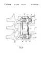
- FIG. 8shows the system from FIG. 1 fixed on vertebrae.
- the systemcomprises, in the preferred embodiment, a first elongate connection rod 2 , or main rod, of circular cross section, a second elongate connection rod 3 or secondary rod of circular cross section and several connector sub-assemblies 4 which can be fixed simultaneously to the latter.
- Each of these sub-assembliescomprises a connector 6 , a first vertebral screw or main screw 8 , a clamping screw 10 , a second vertebral screw or secondary screw 12 , and a ring 13 .
- the connector 6is made in one piece.
- the different parts of the systemare made of biocompatible metal.
- the preferred connector 6includes two branches 16 extending opposite to and at a distance from each other, giving the connector a general U-shaped profile.
- the connector 6includes a plane of symmetry S visible in FIGS. 3 and 6, perpendicular to the width of the branches 16 and parallel to their length.
- each branchhas a first end and a second end.
- the branchesare connected to each other via their first ends.
- the second endsare free ends
- the connectorat the point of origin of the branches 16 , that is to say of their first end, the connector has two cylindrical and coaxial inner faces 18 , 20 with axis 22 perpendicular to the plane S and with different radii.
- the face 20 of greater radiusis in two distinct parts and extends on either side of the face 18 of lesser radius, which is traversed by the plane S.
- the two faces 18 , 20form two circular edges 24 with axis 22 .
- the preferred ring 13has a cylindrical inner face 26 and a spherical outer face 28 which are coaxial.
- the cylindrical inner face 26has a radius about equal to that of the main rod 2 in such a way that the ring 13 , slotted on one side along its axis, can be received as a sliding fit on the main rod 2 .
- the ring 13can be lodged between the branches 16 opposite the cylindrical faces 18 , 20 .
- the spherical outer face 28 of the ringhas a radius which is adapted such that in this position the edges 24 of the connector 6 are in linear contact with the spherical outer face 28 of the ring 13 and serve as bearings for it.
- the angular position of the main rod 2 engaged in the ring 13can be controlled in two mutually perpendicular planes over an amplitude of, for example, 15° on either side of a mean position of the rod in which the rod is perpendicular to the plane S.
- the branches 16have two respective smooth cylindrical openings which, in this case, are through-orifices 30 extending coaxially opposite each other.
- the preferred main screw 8is a bicortical vertebral screw and has a threaded body for this purposes, in a manner known per se. Referring to FIG. 7, it has a head 32 having a smooth cylindrical outer face 34 . At the junction between the head and the body, the screw includes an annular flange 36 having a plane lower face perpendicular to a longitudinal axis of the screw, and a frustoconical upper face 38 with the narrowest cross section of the frustum situated towards the head 32 of the screw.
- the head 32has a threaded orifice 39 coaxial to the body of the screw and, formed in the threaded face of the orifice 39 , a noncircular shape such as a hexagon socket.
- the clamping screw 10includes a threaded body 42 which is able to form a screw-nut connection with this orifice 39 , and a screw head 44 in which a hexagon socket is formed.
- the head 44has a spherical and convex lower outer face 46 whose narrowest cross section is situated towards the point of the screw.
- one of the branches 16 of the connector 6which for the sake of clarity we will here call the lower branch, has an extension 50 extending in the direction away from the cylindrical faces 18 , 20 of the connector.
- This extensionhas the second, free, end of the branch.
- the two branches 16are able to be engaged simultaneously on the head 32 of the main screw 8 introduced in the orifices 30 starting from the lower branch against which the upper face 38 of the flange 36 comes into abutment.
- the clamping screw 10is then introduced into the head 32 of the main screw 8 starting from the upper branch 16 .
- the tightening of the clamping screw 10 in the head 32 of the main screw 8causes the branches 16 to move towards each other and causes, inter alia, frictional blocking of the first rod 2 in the chosen position relative to the connector 6 .
- the orifice 30 of the lower branch 16has a lower edge, remote from the upper branch and intended to be towards the vertebra, having a concave spherical recess 40 intended to come into contact with the upper face 38 of the flange 36 in order to effect, by friction, rotational blocking of the connector 6 relative to the axis of the main screw 8 .
- the orifice 30 of the upper branch 16has an upper edge, remote from the lower branch and intended to be remote from the vertebra, having a concave spherical recess 40 intended to come into contact with the convex and spherical lower face 46 of the head 44 of the clamping screw 10 and making it possible to fix the latter and the main screw 8 by controlling the angular orientation of the main screw 8 relative to the connector.
- the extension 50has an opening in the form of a through-orifice 52 .
- the lower branch 16is curved in the area of the extension 50 in a direction away from the upper branch 16 in such a way that the axes of its orifices 30 and 52 are not quite parallel.
- the secondary screw 12is a vertebral screw, here a monocortical screw, having a threaded body and a head 56 with a spherical and convex lower face 58 whose narrowest cross section is situated towards the body. Its head has a hexagon socket.
- the orifice 52 of the extensionhas an upper edge 60 , oriented towards the other branch 16 and intended to be remote from the vertebra, having a spherical and concave or preferably frustoconical form 60 , intended to come into contact with the spherical and convex lower face 58 of the head 56 of the secondary screw 12 , making it possible to control the angular orientation of this screw relative to the connector 6 .
- the lower branch 16can be bent in order to accentuate or reduce its curvature for better adaptation to the shape of the anterior part of the vertebra for which it is intended. Once bent, this branch 16 is no longer stressed in flexion since it is fixed to the vertebra by two screws 8 , 12 along its length.
- the two screwsnamely the main screw 8 and the secondary screw 12 , are self-tapping and include bone threads.
- the main screw 8does not have a hexagon socket in this threaded orifice 39 , and instead the flange 36 has a hexagonal shape or has two parallel and diametrically opposite flats which can cooperate with a tightening wrench for rotating this screw 8 relative to the connector 6 .
- the two connection rods 2 , 3each have a profiled rectilinear shape, the profile here being circular.
- the secondary rod 3has a cross section, transverse to its longitudinal axis, having a diameter smaller than that of the main rod 2 .
- the main rod 2will, for example, have a diameter of 6 mm.
- the diameter of the secondary rod 3will, for example, be between 30% and 80% of the diameter of the main rod 2 . This small diameter allows the surgeon to choose the curvature of the secondary rod 3 corresponding to that of the level of the spine which is being operated on.
- the rings 13allow relative angular positioning of the two connectors 6 , the main rod 2 does not have to be bent. It can thus have a substantial diameter in order to be very robust.
- the branches 16 of the connectorhave respective cylindrical recesses, grooves or jaws 74 formed in the faces of the branches opposite each other.
- the recesses 74extend opposite each other and have axes parallel to each other and perpendicular to the plane of symmetry S.
- the recess 74extends at a free end of the branch such that the orifice 30 is interposed between the faces 18 , 20 , on the one hand, and the recess 74 on the other.
- the recess 74extends between the two orifices 30 and 52 , at the origin of the extension 50 . It is contiguous with the orifice 52 so that it engages on its edge 60 , i.e. recess 74 intercepts the upper opening of orifice 52 as shown in FIG. 3 .
- the secondary rod 3is intended to be received in the recess 74 of the lower branch 16 in a unique angular position relative to the connector, perpendicular to the plane of symmetry S.
- the connector and the rodare dimensioned in such a way that the secondary rod can be introduced laterally between the free ends of the branches (that is to say without engaging the rod via one end in the connector). Before clamping, the space between the branches is wider than the diameter of the rod which can thus be freely inserted.
- the secondary rod 3is placed in the recess 74 of the lower branch after the secondary screw 12 has been introduced into the orifice 52 .
- the position of the recess 74 of the lower branchis such that the secondary rod 3 then extends in the trajectory of the head of the secondary screw 12 for its disengagement from the connector and its exit from the orifice 52 . Consequently, once the secondary rod 3 has been fixed to the connector, the secondary screw 12 can no longer be separated from the connector.
- the upper branch 16 of the connectorhas at its free end a notch 76 which engages recess 74 with which it is contiguous, and facilitates maneuvering of the clamping screw 12 by means of a tool despite the space occupied by the upper branch.
- Such a deviceis fitted in the following manner, with reference to FIG. 8 .
- a vertebrectomyis performed while preserving, if possible, the respective plates of these vertebrae.
- a pilot holeis made on the lateral side of the associated vertebra 72 at an equal distance from the upper and lower plates, and at the limit of the most posterior quarter of the vertebral body.
- the main screw 8is then inserted into this pilot hole as far as the limit flange 36 .
- the connector 6is then positioned on the main screw 8 , blocked in translation by the conical face 38 of the main screw 8 matching the recess 40 of the connector 6 .
- the fit of the lower branch 16 of the connector 6 on the vertebrais then checked and can be adjusted by withdrawing the connector in order to bend, to a greater or lesser extent, the lower branch 16 , which is its most anterior part.
- the secondary screw 12is then screwed relative to the main screw 8 into the second orifice 52 of the lower branch 16 until the spherical seat 60 of the extension, provided for this purpose, comes into contact with the spherical part 58 of the secondary screw 12 . It is desirable to position the connector 6 as parallel as possible to the plates.
- FIG. 1shows the system before the clamping of the branches.
- Final clampingis effected by virtue of the clamping screw 10 which is inserted into the main screw 8 and thereby compresses the connector 6 in order to clamp its two branches 16 towards each other.
- the clamping forceis directed first on the main rod 2 via the ring 13 , until the recess 74 of the upper branch comes into contact, with the secondary rod 3 . Thereafter, the clamping force is distributed on the two rods 2 , 3 .
- the reaction at the level of the pairing of main screw 8 and clamping screw 10is substantially coaxial to these.
- the characteristics relating to the association of the first screw 8 with the clamping screw 10will be able to be implemented independently of the presence of the extension 50 and of the secondary screw 12 .
- the extended branchcan be the one which is intended to be farthest from the vertebra.
Landscapes
- Health & Medical Sciences (AREA)
- Orthopedic Medicine & Surgery (AREA)
- Life Sciences & Earth Sciences (AREA)
- Neurology (AREA)
- Surgery (AREA)
- Molecular Biology (AREA)
- Veterinary Medicine (AREA)
- Biomedical Technology (AREA)
- Heart & Thoracic Surgery (AREA)
- Medical Informatics (AREA)
- Nuclear Medicine, Radiotherapy & Molecular Imaging (AREA)
- Animal Behavior & Ethology (AREA)
- General Health & Medical Sciences (AREA)
- Public Health (AREA)
- Engineering & Computer Science (AREA)
- Surgical Instruments (AREA)
- Prostheses (AREA)
- Electrotherapy Devices (AREA)
- Acyclic And Carbocyclic Compounds In Medicinal Compositions (AREA)
- Pharmaceuticals Containing Other Organic And Inorganic Compounds (AREA)
- Compounds Of Unknown Constitution (AREA)
- Orthopedics, Nursing, And Contraception (AREA)
Abstract
Description
Claims (21)
Applications Claiming Priority (3)
| Application Number | Priority Date | Filing Date | Title |
|---|---|---|---|
| FR9812662AFR2784282B1 (en) | 1998-10-09 | 1998-10-09 | SPINAL OSTEOSYNTHESIS SYSTEM WITH IMPROVED RIGIDITY |
| FR9812662 | 1998-10-09 | ||
| PCT/FR1999/002402WO2000021447A1 (en) | 1998-10-09 | 1999-10-07 | Spinal osteosynthesis system with improved stability |
Publications (1)
| Publication Number | Publication Date |
|---|---|
| US6749612B1true US6749612B1 (en) | 2004-06-15 |
Family
ID=9531369
Family Applications (1)
| Application Number | Title | Priority Date | Filing Date |
|---|---|---|---|
| US09/807,092Expired - Fee RelatedUS6749612B1 (en) | 1998-10-09 | 1999-10-07 | Spinal osteosynthesis system with improved rigidity |
Country Status (12)
| Country | Link |
|---|---|
| US (1) | US6749612B1 (en) |
| EP (1) | EP1119305B8 (en) |
| JP (1) | JP4254060B2 (en) |
| KR (1) | KR20010075607A (en) |
| AT (1) | ATE295703T1 (en) |
| AU (1) | AU764003B2 (en) |
| CA (1) | CA2346505A1 (en) |
| DE (2) | DE69925374T2 (en) |
| ES (1) | ES2167295T1 (en) |
| FR (1) | FR2784282B1 (en) |
| WO (1) | WO2000021447A1 (en) |
| ZA (1) | ZA200102859B (en) |
Cited By (49)
| Publication number | Priority date | Publication date | Assignee | Title |
|---|---|---|---|---|
| US20040039385A1 (en)* | 2000-12-07 | 2004-02-26 | Keyvan Mazda | Device for fixing a rod and a spherical symmetry screw head |
| US20040116932A1 (en)* | 2001-02-22 | 2004-06-17 | Keyvan Mazda | Fixing screw |
| US20040220668A1 (en)* | 2003-02-12 | 2004-11-04 | Sdgi Holdings, Inc. | Method and device for correcting spondylolisthesis from the lateral approach |
| US20050182409A1 (en)* | 2003-05-02 | 2005-08-18 | Ronald Callahan | Systems and methods accommodating relative motion in spine stabilization |
| US20050277920A1 (en)* | 2004-05-28 | 2005-12-15 | Slivka Michael A | Non-fusion spinal correction systems and methods |
| WO2007056709A2 (en) | 2005-11-04 | 2007-05-18 | Warsaw Orthopedic, Inc. | Dorsal adjusting multi-rod connector |
| US20070118124A1 (en)* | 2001-10-23 | 2007-05-24 | Lutz Biedermann | Bone fixation device and screw therefor |
| US20070161987A1 (en)* | 2005-12-15 | 2007-07-12 | Sdgi Holdings, Inc. | Variable angle offset spinal connector assembly |
| US20070161995A1 (en)* | 2005-10-06 | 2007-07-12 | Trautwein Frank T | Polyaxial Screw |
| US20070191844A1 (en)* | 2006-01-31 | 2007-08-16 | Sdgi Holdings, Inc. | In-series, dual locking mechanism device |
| US20070233066A1 (en)* | 2006-02-17 | 2007-10-04 | Sdgi Holdings, Inc. | Dorsal adjusting spinal connector assembly |
| US20070233070A1 (en)* | 2006-03-01 | 2007-10-04 | Sdgi Holdings, Inc. | Low profile spinal rod connector system |
| US20080015580A1 (en)* | 2006-04-28 | 2008-01-17 | Nam Chao | Large diameter bone anchor assembly |
| US20080262553A1 (en)* | 2007-04-18 | 2008-10-23 | Ebi, Llc | Spinal connector |
| WO2009001978A1 (en)* | 2007-06-22 | 2008-12-31 | Gs Medical Co., Ltd. | A rod clamp |
| WO2009049161A3 (en)* | 2007-10-12 | 2009-06-25 | Synthes Usa | Reconstruction device |
| US7575600B2 (en) | 2004-09-29 | 2009-08-18 | Kyphon Sarl | Artificial vertebral disk replacement implant with translating articulation contact surface and method |
| US7628799B2 (en) | 2005-08-23 | 2009-12-08 | Aesculap Ag & Co. Kg | Rod to rod connector |
| US20100125333A1 (en)* | 1995-03-27 | 2010-05-20 | Thomas Zdeblick | Methods and instruments for interbody fusion |
| US7744632B2 (en) | 2006-12-20 | 2010-06-29 | Aesculap Implant Systems, Inc. | Rod to rod connector |
| US8361123B2 (en) | 2009-10-16 | 2013-01-29 | Depuy Spine, Inc. | Bone anchor assemblies and methods of manufacturing and use thereof |
| US20130253586A1 (en)* | 2007-09-25 | 2013-09-26 | David S. Rathbun | Transconnector |
| US8771319B2 (en) | 2012-04-16 | 2014-07-08 | Aesculap Implant Systems, Llc | Rod to rod cross connector |
| US8828056B2 (en) | 2012-04-16 | 2014-09-09 | Aesculap Implant Systems, Llc | Rod to rod cross connector |
| US8828058B2 (en) | 2008-11-11 | 2014-09-09 | Kspine, Inc. | Growth directed vertebral fixation system with distractible connector(s) and apical control |
| US8920471B2 (en) | 2010-07-12 | 2014-12-30 | K2M, Inc. | Transverse connector |
| US8920472B2 (en) | 2011-11-16 | 2014-12-30 | Kspine, Inc. | Spinal correction and secondary stabilization |
| US8992579B1 (en)* | 2011-03-08 | 2015-03-31 | Nuvasive, Inc. | Lateral fixation constructs and related methods |
| US9011491B2 (en) | 2004-08-03 | 2015-04-21 | K Spine, Inc. | Facet device and method |
| US9060815B1 (en) | 2012-03-08 | 2015-06-23 | Nuvasive, Inc. | Systems and methods for performing spine surgery |
| US20150223844A1 (en)* | 2011-07-15 | 2015-08-13 | Globus Medical, Inc. | Orthopedic fixation devices and methods of installation thereof |
| US9168071B2 (en) | 2009-09-15 | 2015-10-27 | K2M, Inc. | Growth modulation system |
| US9173681B2 (en) | 2009-03-26 | 2015-11-03 | K2M, Inc. | Alignment system with longitudinal support features |
| US9333009B2 (en) | 2011-06-03 | 2016-05-10 | K2M, Inc. | Spinal correction system actuators |
| US20160128732A1 (en)* | 2014-11-11 | 2016-05-12 | Intrepid Orthopedics | Supplemental Fixation Screw |
| US9451987B2 (en) | 2011-11-16 | 2016-09-27 | K2M, Inc. | System and method for spinal correction |
| US9468471B2 (en) | 2013-09-17 | 2016-10-18 | K2M, Inc. | Transverse coupler adjuster spinal correction systems and methods |
| US9468469B2 (en) | 2011-11-16 | 2016-10-18 | K2M, Inc. | Transverse coupler adjuster spinal correction systems and methods |
| US9468468B2 (en) | 2011-11-16 | 2016-10-18 | K2M, Inc. | Transverse connector for spinal stabilization system |
| US9517089B1 (en) | 2013-10-08 | 2016-12-13 | Nuvasive, Inc. | Bone anchor with offset rod connector |
| US9763703B2 (en) | 2015-05-05 | 2017-09-19 | Degen Medical, Inc. | Cross connectors, kits, and methods |
| US9907578B2 (en)* | 2008-09-05 | 2018-03-06 | Biedermann Technologies Gmbh & Co. Kg | Bone anchoring element and stabilization device for bones, in particular for the spinal column |
| US9942511B2 (en) | 2005-10-31 | 2018-04-10 | Invention Science Fund I, Llc | Preservation/degradation of video/audio aspects of a data stream |
| EP3366242A1 (en)* | 2017-02-24 | 2018-08-29 | Warsaw Orthopedic, Inc. | Spinal implant system |
| US10166054B2 (en) | 2013-07-09 | 2019-01-01 | DePuy Synthes Products, Inc. | Bone fixation system |
| US10405893B2 (en) | 2012-07-12 | 2019-09-10 | DePuy Synthes Products, Inc. | Device, kit and method for correction of spinal deformity |
| US10702311B2 (en) | 2011-11-16 | 2020-07-07 | K2M, Inc. | Spinal correction and secondary stabilization |
| US10980584B2 (en) | 2016-08-16 | 2021-04-20 | DePuy Synthes Products, Inc. | Bone fixation system |
| US11000322B2 (en) | 2018-09-20 | 2021-05-11 | DePuy Synthes Products, Inc. | Bone fixation system |
Families Citing this family (4)
| Publication number | Priority date | Publication date | Assignee | Title |
|---|---|---|---|---|
| FR2836368B1 (en)* | 2002-02-25 | 2005-01-14 | Spine Next Sa | SEQUENTIAL LINK DEVICE |
| US8034082B2 (en) | 2004-07-08 | 2011-10-11 | Globus Medical, Inc. | Transverse fixation device for spinal fixation systems |
| US8435267B2 (en)* | 2006-04-24 | 2013-05-07 | Spinefrontier Inc | Spine fixation method and apparatus |
| RU2333731C1 (en)* | 2007-02-05 | 2008-09-20 | Федеральное государственное унитарное предприятие "Красноярский машиностроительный завод" ФГУП "Красмаш" | Fastener assembly of endodevice rod |
Citations (33)
| Publication number | Priority date | Publication date | Assignee | Title |
|---|---|---|---|---|
| FR2244446A1 (en) | 1973-09-21 | 1975-04-18 | Cotrel Yves | Traction device for scoliosis - tensioner rod clamped across vert. rods tensions vertebrae under max stress |
| US4289123A (en) | 1980-03-31 | 1981-09-15 | Dunn Harold K | Orthopedic appliance |
| US4987892A (en) | 1989-04-04 | 1991-01-29 | Krag Martin H | Spinal fixation device |
| US5108395A (en) | 1989-09-18 | 1992-04-28 | Societe De Fabrication De Materiel Orthopedique - Sofamor | Implant for anterior dorsolumbar spinal osteosynthesis, intended for the correction of kyphoses |
| US5147360A (en) | 1990-02-19 | 1992-09-15 | Societe De Fabrication De Materiel Orthopedique | Osteosynthesis device for the correction of spinal curvatures |
| US5236460A (en) | 1990-02-12 | 1993-08-17 | Midas Rex Pneumatic Tools, Inc. | Vertebral body prosthesis |
| WO1993020771A1 (en)* | 1992-04-10 | 1993-10-28 | Eurosurgical | Spinal osteosynthesis device |
| WO1994006360A1 (en) | 1992-09-24 | 1994-03-31 | Danek Medical, Inc. | Anterior thoracolumbar plate |
| FR2697744A1 (en) | 1992-11-10 | 1994-05-13 | Fabrication Mat Orthopedique S | Spinal osteosynthesis instrumentation by the anterior route. |
| US5380324A (en) | 1992-05-18 | 1995-01-10 | Pina Vertriebs Ag | Implantable device for straightening and fixing vertebrae |
| DE9412744U1 (en) | 1994-08-06 | 1995-12-07 | Schäfer micomed GmbH, 73614 Schorndorf | Bone surgery holding device |
| DE4433360A1 (en)* | 1994-07-19 | 1996-02-01 | Schaefer Micomed Gmbh | Surgical fixator rod holder |
| EP0697200A1 (en) | 1994-08-20 | 1996-02-21 | Schäfer micomed GmbH | Ventral intervertebral implant |
| DE19534136A1 (en) | 1994-09-15 | 1996-03-21 | Tornier Sa | External or internal fixator for skeletal arthroplasty |
| FR2730159A1 (en) | 1995-02-06 | 1996-08-09 | Teule Jean Germain | Intervertebral disc prosthesis for reduced stress and natural movement |
| EP0726064A2 (en) | 1995-01-25 | 1996-08-14 | Danek Medical, Inc. | Screw-rod-connector of an anterior spiral fixation device |
| WO1996027340A1 (en) | 1995-03-06 | 1996-09-12 | Stryker France S.A. | Spinal instruments, particularly for a rod |
| US5609635A (en) | 1988-06-28 | 1997-03-11 | Michelson; Gary K. | Lordotic interbody spinal fusion implants |
| US5628740A (en) | 1993-12-23 | 1997-05-13 | Mullane; Thomas S. | Articulating toggle bolt bone screw |
| US5662652A (en) | 1994-04-28 | 1997-09-02 | Schafer Micomed Gmbh | Bone surgery holding apparatus |
| DE29712697U1 (en) | 1997-07-18 | 1997-09-25 | ENDOTEC Vertriebs- und Beratungsgesellschaft für Medizintechnik mbH, 51399 Burscheid | Spinal fixator |
| US5683391A (en) | 1995-06-07 | 1997-11-04 | Danek Medical, Inc. | Anterior spinal instrumentation and method for implantation and revision |
| US5702395A (en)* | 1992-11-10 | 1997-12-30 | Sofamor S.N.C. | Spine osteosynthesis instrumentation for an anterior approach |
| US5713898A (en) | 1993-05-18 | 1998-02-03 | Schafer Micomed Gmbh | Orthopedic surgical holding device |
| US5800550A (en) | 1996-03-13 | 1998-09-01 | Sertich; Mario M. | Interbody fusion cage |
| US6004322A (en) | 1994-10-25 | 1999-12-21 | Sdgi Holdings, Inc. | Modular pedicle screw system |
| WO2000001314A1 (en) | 1998-07-06 | 2000-01-13 | Dimso (Distribution Medicale Du Sud-Ouest) | Backbone osteosynthesis device for anterior fixing with plate |
| US6123706A (en) | 1997-12-17 | 2000-09-26 | Lange; Robert | Apparatus for stabilizing certain vertebrae of the spine |
| US6132431A (en) | 1996-04-18 | 2000-10-17 | Tresona Instrument Ab | Device and method for correcting and stabilizing a deviating curvature of a spinal column |
| US6146383A (en)* | 1998-02-02 | 2000-11-14 | Sulzer Orthopadie Ag | Pivotal securing system at a bone screw |
| US6299614B1 (en) | 1999-03-29 | 2001-10-09 | Signus Medizintechnik Gmbh | Device for stabilizing vertebra bodies of the spinal column |
| US6328739B1 (en) | 1999-05-04 | 2001-12-11 | Industrial Technology Research Institute | Enhanced spine fixation apparatus |
| US6423064B1 (en) | 1999-09-15 | 2002-07-23 | Ulrich Gmbh & Co. Kg | Orthopaedic screw variable angle connection to a longitudinal support |
Family Cites Families (1)
| Publication number | Priority date | Publication date | Assignee | Title |
|---|---|---|---|---|
| US5613968A (en)* | 1995-05-01 | 1997-03-25 | Lin; Chih-I | Universal pad fixation device for orthopedic surgery |
- 1998
- 1998-10-09FRFR9812662Apatent/FR2784282B1/ennot_activeExpired - Fee Related
- 1999
- 1999-10-07ATAT99970307Tpatent/ATE295703T1/ennot_activeIP Right Cessation
- 1999-10-07EPEP99970307Apatent/EP1119305B8/ennot_activeExpired - Lifetime
- 1999-10-07JPJP2000575431Apatent/JP4254060B2/ennot_activeExpired - Fee Related
- 1999-10-07WOPCT/FR1999/002402patent/WO2000021447A1/enactiveIP Right Grant
- 1999-10-07USUS09/807,092patent/US6749612B1/ennot_activeExpired - Fee Related
- 1999-10-07KRKR1020017004489Apatent/KR20010075607A/ennot_activeWithdrawn
- 1999-10-07DEDE69925374Tpatent/DE69925374T2/ennot_activeExpired - Lifetime
- 1999-10-07AUAU59906/99Apatent/AU764003B2/ennot_activeCeased
- 1999-10-07CACA002346505Apatent/CA2346505A1/ennot_activeAbandoned
- 1999-10-07DEDE1119305Tpatent/DE1119305T1/enactivePending
- 1999-10-07ESES99970307Tpatent/ES2167295T1/enactivePending
- 2001
- 2001-04-06ZAZA200102859Apatent/ZA200102859B/enunknown
Patent Citations (35)
| Publication number | Priority date | Publication date | Assignee | Title |
|---|---|---|---|---|
| FR2244446A1 (en) | 1973-09-21 | 1975-04-18 | Cotrel Yves | Traction device for scoliosis - tensioner rod clamped across vert. rods tensions vertebrae under max stress |
| US4289123A (en) | 1980-03-31 | 1981-09-15 | Dunn Harold K | Orthopedic appliance |
| US5609635A (en) | 1988-06-28 | 1997-03-11 | Michelson; Gary K. | Lordotic interbody spinal fusion implants |
| US4987892A (en) | 1989-04-04 | 1991-01-29 | Krag Martin H | Spinal fixation device |
| US5108395A (en) | 1989-09-18 | 1992-04-28 | Societe De Fabrication De Materiel Orthopedique - Sofamor | Implant for anterior dorsolumbar spinal osteosynthesis, intended for the correction of kyphoses |
| US5236460A (en) | 1990-02-12 | 1993-08-17 | Midas Rex Pneumatic Tools, Inc. | Vertebral body prosthesis |
| US5147360A (en) | 1990-02-19 | 1992-09-15 | Societe De Fabrication De Materiel Orthopedique | Osteosynthesis device for the correction of spinal curvatures |
| WO1993020771A1 (en)* | 1992-04-10 | 1993-10-28 | Eurosurgical | Spinal osteosynthesis device |
| US5380324A (en) | 1992-05-18 | 1995-01-10 | Pina Vertriebs Ag | Implantable device for straightening and fixing vertebrae |
| WO1994006360A1 (en) | 1992-09-24 | 1994-03-31 | Danek Medical, Inc. | Anterior thoracolumbar plate |
| FR2697744A1 (en) | 1992-11-10 | 1994-05-13 | Fabrication Mat Orthopedique S | Spinal osteosynthesis instrumentation by the anterior route. |
| US5702395A (en)* | 1992-11-10 | 1997-12-30 | Sofamor S.N.C. | Spine osteosynthesis instrumentation for an anterior approach |
| US5713898A (en) | 1993-05-18 | 1998-02-03 | Schafer Micomed Gmbh | Orthopedic surgical holding device |
| US5628740A (en) | 1993-12-23 | 1997-05-13 | Mullane; Thomas S. | Articulating toggle bolt bone screw |
| US5662652A (en) | 1994-04-28 | 1997-09-02 | Schafer Micomed Gmbh | Bone surgery holding apparatus |
| DE4433360A1 (en)* | 1994-07-19 | 1996-02-01 | Schaefer Micomed Gmbh | Surgical fixator rod holder |
| DE9412744U1 (en) | 1994-08-06 | 1995-12-07 | Schäfer micomed GmbH, 73614 Schorndorf | Bone surgery holding device |
| EP0697200A1 (en) | 1994-08-20 | 1996-02-21 | Schäfer micomed GmbH | Ventral intervertebral implant |
| DE19534136A1 (en) | 1994-09-15 | 1996-03-21 | Tornier Sa | External or internal fixator for skeletal arthroplasty |
| US6004322A (en) | 1994-10-25 | 1999-12-21 | Sdgi Holdings, Inc. | Modular pedicle screw system |
| US5620443A (en)* | 1995-01-25 | 1997-04-15 | Danek Medical, Inc. | Anterior screw-rod connector |
| EP0726064A2 (en) | 1995-01-25 | 1996-08-14 | Danek Medical, Inc. | Screw-rod-connector of an anterior spiral fixation device |
| FR2730159A1 (en) | 1995-02-06 | 1996-08-09 | Teule Jean Germain | Intervertebral disc prosthesis for reduced stress and natural movement |
| WO1996027340A1 (en) | 1995-03-06 | 1996-09-12 | Stryker France S.A. | Spinal instruments, particularly for a rod |
| US5938663A (en) | 1995-03-06 | 1999-08-17 | Stryker France, S.A. | Spinal instruments, particularly for a rod |
| US5683391A (en) | 1995-06-07 | 1997-11-04 | Danek Medical, Inc. | Anterior spinal instrumentation and method for implantation and revision |
| US5800550A (en) | 1996-03-13 | 1998-09-01 | Sertich; Mario M. | Interbody fusion cage |
| US6132431A (en) | 1996-04-18 | 2000-10-17 | Tresona Instrument Ab | Device and method for correcting and stabilizing a deviating curvature of a spinal column |
| DE29712697U1 (en) | 1997-07-18 | 1997-09-25 | ENDOTEC Vertriebs- und Beratungsgesellschaft für Medizintechnik mbH, 51399 Burscheid | Spinal fixator |
| US6123706A (en) | 1997-12-17 | 2000-09-26 | Lange; Robert | Apparatus for stabilizing certain vertebrae of the spine |
| US6146383A (en)* | 1998-02-02 | 2000-11-14 | Sulzer Orthopadie Ag | Pivotal securing system at a bone screw |
| WO2000001314A1 (en) | 1998-07-06 | 2000-01-13 | Dimso (Distribution Medicale Du Sud-Ouest) | Backbone osteosynthesis device for anterior fixing with plate |
| US6299614B1 (en) | 1999-03-29 | 2001-10-09 | Signus Medizintechnik Gmbh | Device for stabilizing vertebra bodies of the spinal column |
| US6328739B1 (en) | 1999-05-04 | 2001-12-11 | Industrial Technology Research Institute | Enhanced spine fixation apparatus |
| US6423064B1 (en) | 1999-09-15 | 2002-07-23 | Ulrich Gmbh & Co. Kg | Orthopaedic screw variable angle connection to a longitudinal support |
Cited By (103)
| Publication number | Priority date | Publication date | Assignee | Title |
|---|---|---|---|---|
| US7985258B2 (en)* | 1995-03-27 | 2011-07-26 | Warsaw Orthopedic Inc. | Methods and instruments for interbody fusion |
| US20100125333A1 (en)* | 1995-03-27 | 2010-05-20 | Thomas Zdeblick | Methods and instruments for interbody fusion |
| US20040039385A1 (en)* | 2000-12-07 | 2004-02-26 | Keyvan Mazda | Device for fixing a rod and a spherical symmetry screw head |
| US7166108B2 (en)* | 2000-12-07 | 2007-01-23 | Abbott Spine | Device for fixing a rod and a spherical symmetry screw head |
| US20040116932A1 (en)* | 2001-02-22 | 2004-06-17 | Keyvan Mazda | Fixing screw |
| US8052725B2 (en) | 2001-10-23 | 2011-11-08 | Biedermann Motech Gmbh | Bone fixation device and screw therefor |
| US20070118124A1 (en)* | 2001-10-23 | 2007-05-24 | Lutz Biedermann | Bone fixation device and screw therefor |
| US20040220668A1 (en)* | 2003-02-12 | 2004-11-04 | Sdgi Holdings, Inc. | Method and device for correcting spondylolisthesis from the lateral approach |
| US20100324684A1 (en)* | 2003-02-12 | 2010-12-23 | Warsaw Orthopedic, Inc. | Spinal Prosthetic Joints |
| US7635379B2 (en)* | 2003-05-02 | 2009-12-22 | Applied Spine Technologies, Inc. | Pedicle screw assembly with bearing surfaces |
| US20050182409A1 (en)* | 2003-05-02 | 2005-08-18 | Ronald Callahan | Systems and methods accommodating relative motion in spine stabilization |
| US8034085B2 (en)* | 2004-05-28 | 2011-10-11 | Depuy Spine, Inc. | Non-fusion spinal correction systems and methods |
| US20050277920A1 (en)* | 2004-05-28 | 2005-12-15 | Slivka Michael A | Non-fusion spinal correction systems and methods |
| US8506602B2 (en) | 2004-05-28 | 2013-08-13 | DePuy Synthes Products, LLC | Non-fusion spinal correction systems and methods |
| US9451997B2 (en) | 2004-08-03 | 2016-09-27 | K2M, Inc. | Facet device and method |
| US9011491B2 (en) | 2004-08-03 | 2015-04-21 | K Spine, Inc. | Facet device and method |
| US7575600B2 (en) | 2004-09-29 | 2009-08-18 | Kyphon Sarl | Artificial vertebral disk replacement implant with translating articulation contact surface and method |
| US7628799B2 (en) | 2005-08-23 | 2009-12-08 | Aesculap Ag & Co. Kg | Rod to rod connector |
| US20070161995A1 (en)* | 2005-10-06 | 2007-07-12 | Trautwein Frank T | Polyaxial Screw |
| US7927359B2 (en) | 2005-10-06 | 2011-04-19 | Paradigm Spine, Llc | Polyaxial screw |
| US8470001B2 (en) | 2005-10-06 | 2013-06-25 | Paradigm Spine, Llc | Polyaxial screw |
| US9942511B2 (en) | 2005-10-31 | 2018-04-10 | Invention Science Fund I, Llc | Preservation/degradation of video/audio aspects of a data stream |
| AU2006311274B2 (en)* | 2005-11-04 | 2010-06-24 | Warsaw Orthopedic, Inc. | Dorsal adjusting multi-rod connector |
| US7803174B2 (en) | 2005-11-04 | 2010-09-28 | Warsaw Orthopedic, Inc. | Dorsal adjusting multi-rod connector |
| WO2007056709A2 (en) | 2005-11-04 | 2007-05-18 | Warsaw Orthopedic, Inc. | Dorsal adjusting multi-rod connector |
| US20070123860A1 (en)* | 2005-11-04 | 2007-05-31 | Sdgi Holdings, Inc. | Dorsal adjusting multi-rod connector |
| WO2007056709A3 (en)* | 2005-11-04 | 2007-10-11 | Warsaw Orthopedic Inc | Dorsal adjusting multi-rod connector |
| US20070161987A1 (en)* | 2005-12-15 | 2007-07-12 | Sdgi Holdings, Inc. | Variable angle offset spinal connector assembly |
| US8029546B2 (en) | 2005-12-15 | 2011-10-04 | Warsaw Orthopedic, Inc. | Variable angle offset spinal connector assembly |
| US20070191844A1 (en)* | 2006-01-31 | 2007-08-16 | Sdgi Holdings, Inc. | In-series, dual locking mechanism device |
| US7585299B2 (en) | 2006-02-17 | 2009-09-08 | Warsaw Orthopedic, Inc. | Dorsal adjusting spinal connector assembly |
| US20070233066A1 (en)* | 2006-02-17 | 2007-10-04 | Sdgi Holdings, Inc. | Dorsal adjusting spinal connector assembly |
| US20070233070A1 (en)* | 2006-03-01 | 2007-10-04 | Sdgi Holdings, Inc. | Low profile spinal rod connector system |
| US7699874B2 (en)* | 2006-03-01 | 2010-04-20 | Warsaw Orthopedic, Inc. | Low profile spinal rod connector system |
| US8361129B2 (en) | 2006-04-28 | 2013-01-29 | Depuy Spine, Inc. | Large diameter bone anchor assembly |
| US20080015580A1 (en)* | 2006-04-28 | 2008-01-17 | Nam Chao | Large diameter bone anchor assembly |
| US7744632B2 (en) | 2006-12-20 | 2010-06-29 | Aesculap Implant Systems, Inc. | Rod to rod connector |
| US20080262553A1 (en)* | 2007-04-18 | 2008-10-23 | Ebi, Llc | Spinal connector |
| US8337527B2 (en) | 2007-04-18 | 2012-12-25 | Ebi, Llc | Spinal connector |
| EP1982663A3 (en)* | 2007-04-18 | 2009-04-01 | Ebi, Llc | Spinal connector |
| WO2009001978A1 (en)* | 2007-06-22 | 2008-12-31 | Gs Medical Co., Ltd. | A rod clamp |
| KR100896043B1 (en) | 2007-06-22 | 2009-05-11 | 주식회사 지에스메디칼 | Rod clamp |
| US9510870B2 (en)* | 2007-09-25 | 2016-12-06 | DePuy Synthes Products, Inc. | Transconnector |
| US9949768B2 (en) | 2007-09-25 | 2018-04-24 | DePuy Synthes Products, Inc. | Transconnector |
| US20130253586A1 (en)* | 2007-09-25 | 2013-09-26 | David S. Rathbun | Transconnector |
| US8795277B2 (en) | 2007-10-12 | 2014-08-05 | DePuy Synthes Products, LLC | Reconstruction device |
| CN101808589B (en)* | 2007-10-12 | 2014-06-25 | 斯恩蒂斯有限公司 | Reconstruction device |
| US20100305569A1 (en)* | 2007-10-12 | 2010-12-02 | Synthes (U.S.A.) | Reconstruction device |
| WO2009049161A3 (en)* | 2007-10-12 | 2009-06-25 | Synthes Usa | Reconstruction device |
| EP3431028A1 (en)* | 2007-10-12 | 2019-01-23 | Synthes GmbH | Reconstruction device |
| US10219848B2 (en) | 2007-10-12 | 2019-03-05 | DePuy Synthes Products, Inc. | Reconstruction device |
| US9907578B2 (en)* | 2008-09-05 | 2018-03-06 | Biedermann Technologies Gmbh & Co. Kg | Bone anchoring element and stabilization device for bones, in particular for the spinal column |
| US10842536B2 (en) | 2008-11-11 | 2020-11-24 | K2M, Inc. | Growth directed vertebral fixation system with distractible connector(s) and apical control |
| US9510865B2 (en) | 2008-11-11 | 2016-12-06 | K2M, Inc. | Growth directed vertebral fixation system with distractible connector(s) and apical control |
| US8828058B2 (en) | 2008-11-11 | 2014-09-09 | Kspine, Inc. | Growth directed vertebral fixation system with distractible connector(s) and apical control |
| US12137943B2 (en) | 2009-03-26 | 2024-11-12 | K2M, Inc. | Semi-constrained anchoring system |
| US9173681B2 (en) | 2009-03-26 | 2015-11-03 | K2M, Inc. | Alignment system with longitudinal support features |
| US9358044B2 (en) | 2009-03-26 | 2016-06-07 | K2M, Inc. | Semi-constrained anchoring system |
| US11154329B2 (en) | 2009-03-26 | 2021-10-26 | K2M, Inc. | Semi-constrained anchoring system |
| US9827022B2 (en) | 2009-09-15 | 2017-11-28 | K2M, Llc | Growth modulation system |
| US10736669B2 (en) | 2009-09-15 | 2020-08-11 | K2M, Inc. | Growth modulation system |
| US9168071B2 (en) | 2009-09-15 | 2015-10-27 | K2M, Inc. | Growth modulation system |
| US9161782B2 (en) | 2009-10-16 | 2015-10-20 | DePuy Synthes Products, Inc. | Bone anchor assemblies and methods of manufacturing and use thereof |
| US8361123B2 (en) | 2009-10-16 | 2013-01-29 | Depuy Spine, Inc. | Bone anchor assemblies and methods of manufacturing and use thereof |
| US9504500B2 (en) | 2010-07-12 | 2016-11-29 | K2M, Inc. | Transverse connector |
| US9827021B2 (en) | 2010-07-12 | 2017-11-28 | K2M, Inc. | Transverse connector |
| US8920471B2 (en) | 2010-07-12 | 2014-12-30 | K2M, Inc. | Transverse connector |
| US8992579B1 (en)* | 2011-03-08 | 2015-03-31 | Nuvasive, Inc. | Lateral fixation constructs and related methods |
| US9895168B2 (en) | 2011-06-03 | 2018-02-20 | K2M, Inc. | Spinal correction system actuators |
| US10675062B2 (en) | 2011-06-03 | 2020-06-09 | K2M, Inc. | Spinal correction system actuators |
| US9333009B2 (en) | 2011-06-03 | 2016-05-10 | K2M, Inc. | Spinal correction system actuators |
| US9408638B2 (en) | 2011-06-03 | 2016-08-09 | K2M, Inc. | Spinal correction system actuators |
| US20150223844A1 (en)* | 2011-07-15 | 2015-08-13 | Globus Medical, Inc. | Orthopedic fixation devices and methods of installation thereof |
| US9603635B2 (en)* | 2011-07-15 | 2017-03-28 | Globus Medical, Inc | Orthopedic fixation devices and methods of installation thereof |
| US8920472B2 (en) | 2011-11-16 | 2014-12-30 | Kspine, Inc. | Spinal correction and secondary stabilization |
| US10702311B2 (en) | 2011-11-16 | 2020-07-07 | K2M, Inc. | Spinal correction and secondary stabilization |
| US9468469B2 (en) | 2011-11-16 | 2016-10-18 | K2M, Inc. | Transverse coupler adjuster spinal correction systems and methods |
| US9451987B2 (en) | 2011-11-16 | 2016-09-27 | K2M, Inc. | System and method for spinal correction |
| US9827017B2 (en) | 2011-11-16 | 2017-11-28 | K2M, Inc. | Spinal correction and secondary stabilization |
| US9757157B2 (en) | 2011-11-16 | 2017-09-12 | K2M, Inc. | System and method for spinal correction |
| US10342581B2 (en) | 2011-11-16 | 2019-07-09 | K2M, Inc. | System and method for spinal correction |
| US11013538B2 (en) | 2011-11-16 | 2021-05-25 | K2M, Inc. | System and method for spinal correction |
| US9113959B2 (en) | 2011-11-16 | 2015-08-25 | K2M, Inc. | Spinal correction and secondary stabilization |
| US9468468B2 (en) | 2011-11-16 | 2016-10-18 | K2M, Inc. | Transverse connector for spinal stabilization system |
| US9579131B1 (en) | 2012-03-08 | 2017-02-28 | Nuvasive, Inc. | Systems and methods for performing spine surgery |
| US9060815B1 (en) | 2012-03-08 | 2015-06-23 | Nuvasive, Inc. | Systems and methods for performing spine surgery |
| US8771319B2 (en) | 2012-04-16 | 2014-07-08 | Aesculap Implant Systems, Llc | Rod to rod cross connector |
| US8828056B2 (en) | 2012-04-16 | 2014-09-09 | Aesculap Implant Systems, Llc | Rod to rod cross connector |
| US11602378B2 (en) | 2012-07-12 | 2023-03-14 | DePuy Synthes Products, Inc. | Device, kit and method for correction of spinal deformity |
| US12396761B2 (en) | 2012-07-12 | 2025-08-26 | DePuy Synthes Products, Inc. | Device, kit and method for correction of spinal deformity |
| US10405893B2 (en) | 2012-07-12 | 2019-09-10 | DePuy Synthes Products, Inc. | Device, kit and method for correction of spinal deformity |
| US10166054B2 (en) | 2013-07-09 | 2019-01-01 | DePuy Synthes Products, Inc. | Bone fixation system |
| US10188439B2 (en) | 2013-07-09 | 2019-01-29 | DePuy Synthes Products, Inc. | Bone fixation system |
| US10932836B2 (en) | 2013-07-09 | 2021-03-02 | DePuy Synthes Products, Inc. | Bone fixation system |
| US9468471B2 (en) | 2013-09-17 | 2016-10-18 | K2M, Inc. | Transverse coupler adjuster spinal correction systems and methods |
| US9517089B1 (en) | 2013-10-08 | 2016-12-13 | Nuvasive, Inc. | Bone anchor with offset rod connector |
| US20160128732A1 (en)* | 2014-11-11 | 2016-05-12 | Intrepid Orthopedics | Supplemental Fixation Screw |
| US9649133B2 (en)* | 2014-11-11 | 2017-05-16 | Intrepid Orthopedics | Supplemental fixation screw |
| US9763703B2 (en) | 2015-05-05 | 2017-09-19 | Degen Medical, Inc. | Cross connectors, kits, and methods |
| US10980584B2 (en) | 2016-08-16 | 2021-04-20 | DePuy Synthes Products, Inc. | Bone fixation system |
| US12029457B2 (en) | 2016-08-16 | 2024-07-09 | DePuy Synthes Products, Inc. | Bone fixation system |
| EP3366242A1 (en)* | 2017-02-24 | 2018-08-29 | Warsaw Orthopedic, Inc. | Spinal implant system |
| US11000322B2 (en) | 2018-09-20 | 2021-05-11 | DePuy Synthes Products, Inc. | Bone fixation system |
Also Published As
| Publication number | Publication date |
|---|---|
| CA2346505A1 (en) | 2000-04-20 |
| DE69925374T2 (en) | 2006-01-19 |
| WO2000021447A1 (en) | 2000-04-20 |
| DE69925374D1 (en) | 2005-06-23 |
| KR20010075607A (en) | 2001-08-09 |
| EP1119305B1 (en) | 2005-05-18 |
| JP4254060B2 (en) | 2009-04-15 |
| ZA200102859B (en) | 2001-12-24 |
| EP1119305A1 (en) | 2001-08-01 |
| AU764003B2 (en) | 2003-08-07 |
| ES2167295T1 (en) | 2002-05-16 |
| ATE295703T1 (en) | 2005-06-15 |
| FR2784282A1 (en) | 2000-04-14 |
| DE1119305T1 (en) | 2002-08-22 |
| AU5990699A (en) | 2000-05-01 |
| JP2002527137A (en) | 2002-08-27 |
| EP1119305B8 (en) | 2005-07-13 |
| FR2784282B1 (en) | 2001-03-23 |
Similar Documents
| Publication | Publication Date | Title |
|---|---|---|
| US6749612B1 (en) | Spinal osteosynthesis system with improved rigidity | |
| US7008423B2 (en) | Spinal osteosynthesis system for anterior fixation | |
| EP1663033B1 (en) | Bone fixation assembly and method | |
| EP1788962B1 (en) | Device for securing a spinal rod to the spine | |
| US8361129B2 (en) | Large diameter bone anchor assembly | |
| US7857834B2 (en) | Spinal implant fixation assembly | |
| US5728098A (en) | Multi-angle bone screw assembly using shape-memory technology | |
| US8262702B2 (en) | Osteosynthetic clamp for attaching a bone anchor to a support rod | |
| US20080015597A1 (en) | Large diameter bone anchor assembly | |
| US20060149232A1 (en) | Multi-axial bone screw mechanism | |
| US20080004625A1 (en) | Bone anchor assemblies | |
| US20110087288A1 (en) | Surgical Fixation System and Related Methods | |
| JP2009511171A (en) | Multi-directional moving device for fixing the spine during osteosynthesis surgery | |
| KR19980702816A (en) | Bone Bonding Mechanism for Rod | |
| KR20080040684A (en) | Bipolar corrugated screw assembly | |
| WO2013063477A1 (en) | Top loading polyaxial ball and socket fastener with saddle | |
| MXPA00010648A (en) | Backbone osteosynthesis system with clamping means in particular for anterior fixing |
Legal Events
| Date | Code | Title | Description |
|---|---|---|---|
| AS | Assignment | Owner name:DIMSO (DISTRIBUTION MEDICALE DU SUD-OUEST), FRANCE Free format text:ASSIGNMENT OF ASSIGNORS INTEREST;ASSIGNORS:CONCHY, FREDERIC;ASSAKER, RICHARD;REEL/FRAME:011983/0797 Effective date:20010507 | |
| AS | Assignment | Owner name:STRYKER SPINE, FRANCE Free format text:CHANGE OF NAME;ASSIGNOR:DIMSO SA (DISTRIBUTION MEDICALES DU SUD-OUEST);REEL/FRAME:013758/0410 Effective date:19991102 | |
| FPAY | Fee payment | Year of fee payment:4 | |
| FPAY | Fee payment | Year of fee payment:8 | |
| AS | Assignment | Owner name:STRYKER EUROPEAN HOLDINGS VI, LLC, MICHIGAN Free format text:NUNC PRO TUNC ASSIGNMENT;ASSIGNOR:STRYKER SPINE SAS;REEL/FRAME:037152/0825 Effective date:20151008 Owner name:STRYKER EUROPEAN HOLDINGS I, LLC, MICHIGAN Free format text:NUNC PRO TUNC ASSIGNMENT;ASSIGNOR:STRYKER EUROPEAN HOLDINGS VI, LLC;REEL/FRAME:037153/0391 Effective date:20151008 | |
| REMI | Maintenance fee reminder mailed | ||
| LAPS | Lapse for failure to pay maintenance fees | ||
| STCH | Information on status: patent discontinuation | Free format text:PATENT EXPIRED DUE TO NONPAYMENT OF MAINTENANCE FEES UNDER 37 CFR 1.362 | |
| FP | Lapsed due to failure to pay maintenance fee | Effective date:20160615 | |
| AS | Assignment | Owner name:STRYKER EUROPEAN OPERATIONS HOLDINGS LLC, MICHIGAN Free format text:CHANGE OF NAME;ASSIGNOR:STRYKER EUROPEAN HOLDINGS III, LLC;REEL/FRAME:052860/0716 Effective date:20190226 Owner name:STRYKER EUROPEAN HOLDINGS III, LLC, DELAWARE Free format text:NUNC PRO TUNC ASSIGNMENT;ASSIGNOR:STRYKER EUROPEAN HOLDINGS I, LLC;REEL/FRAME:052861/0001 Effective date:20200519 |