US6749606B2 - Devices for creating collateral channels - Google Patents
Devices for creating collateral channelsDownload PDFInfo
- Publication number
- US6749606B2 US6749606B2US09/946,706US94670601AUS6749606B2US 6749606 B2US6749606 B2US 6749606B2US 94670601 AUS94670601 AUS 94670601AUS 6749606 B2US6749606 B2US 6749606B2
- Authority
- US
- United States
- Prior art keywords
- conduit
- heating element
- airway
- collateral
- lung
- Prior art date
- Legal status (The legal status is an assumption and is not a legal conclusion. Google has not performed a legal analysis and makes no representation as to the accuracy of the status listed.)
- Expired - Lifetime, expires
Links
- 238000010438heat treatmentMethods0.000claimsdescription80
- 239000000463materialSubstances0.000claimsdescription48
- 238000002604ultrasonographyMethods0.000claimsdescription31
- 230000002829reductive effectEffects0.000claimsdescription17
- 230000033001locomotionEffects0.000claimsdescription5
- 210000004072lungAnatomy0.000abstractdescription135
- 208000006545Chronic Obstructive Pulmonary DiseaseDiseases0.000abstractdescription28
- QVGXLLKOCUKJST-UHFFFAOYSA-Natomic oxygenChemical compound[O]QVGXLLKOCUKJST-UHFFFAOYSA-N0.000abstractdescription20
- 239000001301oxygenSubstances0.000abstractdescription20
- 229910052760oxygenInorganic materials0.000abstractdescription20
- 239000008280bloodSubstances0.000abstractdescription15
- CURLTUGMZLYLDI-UHFFFAOYSA-NCarbon dioxideChemical compoundO=C=OCURLTUGMZLYLDI-UHFFFAOYSA-N0.000abstractdescription14
- 210000004369bloodAnatomy0.000abstractdescription14
- 229910002092carbon dioxideInorganic materials0.000abstractdescription7
- 239000001569carbon dioxideSubstances0.000abstractdescription7
- 210000001519tissueAnatomy0.000description81
- 238000000034methodMethods0.000description65
- 210000004204blood vesselAnatomy0.000description41
- 239000012530fluidSubstances0.000description37
- 239000007789gasSubstances0.000description36
- 238000001514detection methodMethods0.000description26
- 210000004712air sacAnatomy0.000description24
- 238000003384imaging methodMethods0.000description20
- 238000009423ventilationMethods0.000description19
- 238000013461designMethods0.000description12
- 210000000621bronchiAnatomy0.000description11
- 230000000694effectsEffects0.000description11
- 239000003814drugSubstances0.000description10
- 239000000523sampleSubstances0.000description10
- 239000000853adhesiveSubstances0.000description9
- 230000001070adhesive effectEffects0.000description9
- 238000002591computed tomographyMethods0.000description9
- 229940079593drugDrugs0.000description9
- 239000000945fillerSubstances0.000description9
- 238000000576coating methodMethods0.000description8
- 238000004891communicationMethods0.000description8
- 230000006870functionEffects0.000description8
- 239000007943implantSubstances0.000description8
- 230000009467reductionEffects0.000description8
- 210000003123bronchioleAnatomy0.000description7
- 230000007423decreaseEffects0.000description7
- 229920001296polysiloxanePolymers0.000description7
- 206010014561EmphysemaDiseases0.000description6
- 239000004593EpoxySubstances0.000description6
- 229940124630bronchodilatorDrugs0.000description6
- 208000037265diseases, disorders, signs and symptomsDiseases0.000description6
- -1polyethylenePolymers0.000description6
- 238000000926separation methodMethods0.000description6
- 238000001356surgical procedureMethods0.000description6
- 206010006458Bronchitis chronicDiseases0.000description5
- 230000004888barrier functionEffects0.000description5
- 230000008901benefitEffects0.000description5
- 230000005540biological transmissionEffects0.000description5
- 206010006451bronchitisDiseases0.000description5
- 210000000845cartilageAnatomy0.000description5
- 239000000919ceramicSubstances0.000description5
- 208000007451chronic bronchitisDiseases0.000description5
- 239000011248coating agentSubstances0.000description5
- 238000010276constructionMethods0.000description5
- 230000008878couplingEffects0.000description5
- 238000010168coupling processMethods0.000description5
- 238000005859coupling reactionMethods0.000description5
- 230000006378damageEffects0.000description5
- 210000000981epitheliumAnatomy0.000description5
- 239000004033plasticSubstances0.000description5
- 229920003023plasticPolymers0.000description5
- 229910001285shape-memory alloyInorganic materials0.000description5
- 239000000126substanceSubstances0.000description5
- 210000000115thoracic cavityAnatomy0.000description5
- JOYRKODLDBILNP-UHFFFAOYSA-NEthyl urethaneChemical compoundCCOC(N)=OJOYRKODLDBILNP-UHFFFAOYSA-N0.000description4
- 229910045601alloyInorganic materials0.000description4
- 239000000956alloySubstances0.000description4
- 238000004140cleaningMethods0.000description4
- 239000013078crystalSubstances0.000description4
- 238000005520cutting processMethods0.000description4
- 229910003460diamondInorganic materials0.000description4
- 239000010432diamondSubstances0.000description4
- 230000010339dilationEffects0.000description4
- 201000010099diseaseDiseases0.000description4
- 229910052751metalInorganic materials0.000description4
- 239000002184metalSubstances0.000description4
- 230000035515penetrationEffects0.000description4
- 229920000642polymerPolymers0.000description4
- 238000009613pulmonary function testMethods0.000description4
- 230000029058respiratory gaseous exchangeEffects0.000description4
- 239000010936titaniumSubstances0.000description4
- 102000009123FibrinHuman genes0.000description3
- 108010073385FibrinProteins0.000description3
- BWGVNKXGVNDBDI-UHFFFAOYSA-NFibrin monomerChemical compoundCNC(=O)CNC(=O)CNBWGVNKXGVNDBDI-UHFFFAOYSA-N0.000description3
- MWCLLHOVUTZFKS-UHFFFAOYSA-NMethyl cyanoacrylateChemical compoundCOC(=O)C(=C)C#NMWCLLHOVUTZFKS-UHFFFAOYSA-N0.000description3
- RTAQQCXQSZGOHL-UHFFFAOYSA-NTitaniumChemical compound[Ti]RTAQQCXQSZGOHL-UHFFFAOYSA-N0.000description3
- 238000005452bendingMethods0.000description3
- 230000015556catabolic processEffects0.000description3
- 239000003795chemical substances by applicationSubstances0.000description3
- 239000004020conductorSubstances0.000description3
- 230000003247decreasing effectEffects0.000description3
- 210000004177elastic tissueAnatomy0.000description3
- 239000000835fiberSubstances0.000description3
- 229950003499fibrinDrugs0.000description3
- 230000035876healingEffects0.000description3
- 230000023597hemostasisEffects0.000description3
- 238000004519manufacturing processMethods0.000description3
- 238000005259measurementMethods0.000description3
- 230000007246mechanismEffects0.000description3
- 210000003097mucusAnatomy0.000description3
- 210000003205muscleAnatomy0.000description3
- 230000036961partial effectEffects0.000description3
- 229920000139polyethylene terephthalatePolymers0.000description3
- 239000005020polyethylene terephthalateSubstances0.000description3
- 229920001343polytetrafluoroethylenePolymers0.000description3
- 239000004810polytetrafluoroethyleneSubstances0.000description3
- 230000008569processEffects0.000description3
- 210000003456pulmonary alveoliAnatomy0.000description3
- 230000002685pulmonary effectEffects0.000description3
- 238000002601radiographyMethods0.000description3
- 238000011084recoveryMethods0.000description3
- 239000007787solidSubstances0.000description3
- 229910052719titaniumInorganic materials0.000description3
- 239000004677NylonSubstances0.000description2
- FAPWRFPIFSIZLT-UHFFFAOYSA-MSodium chlorideChemical compound[Na+].[Cl-]FAPWRFPIFSIZLT-UHFFFAOYSA-M0.000description2
- MCMNRKCIXSYSNV-UHFFFAOYSA-NZirconium dioxideChemical compoundO=[Zr]=OMCMNRKCIXSYSNV-UHFFFAOYSA-N0.000description2
- 230000000712assemblyEffects0.000description2
- 238000000429assemblyMethods0.000description2
- 210000004027cellAnatomy0.000description2
- 239000002131composite materialSubstances0.000description2
- 238000009792diffusion processMethods0.000description2
- 208000035475disorderDiseases0.000description2
- 238000009826distributionMethods0.000description2
- 229920001971elastomerPolymers0.000description2
- 239000000806elastomerSubstances0.000description2
- 210000005081epithelial layerAnatomy0.000description2
- 239000011521glassSubstances0.000description2
- 239000003292glueSubstances0.000description2
- PCHJSUWPFVWCPO-UHFFFAOYSA-NgoldChemical compound[Au]PCHJSUWPFVWCPO-UHFFFAOYSA-N0.000description2
- 229910052737goldInorganic materials0.000description2
- 239000010931goldSubstances0.000description2
- 230000002757inflammatory effectEffects0.000description2
- 230000003434inspiratory effectEffects0.000description2
- 239000012212insulatorSubstances0.000description2
- 230000002427irreversible effectEffects0.000description2
- 238000012423maintenanceMethods0.000description2
- 230000014759maintenance of locationEffects0.000description2
- 150000002739metalsChemical class0.000description2
- 230000003843mucus productionEffects0.000description2
- 229910001000nickel titaniumInorganic materials0.000description2
- 229920001778nylonPolymers0.000description2
- BASFCYQUMIYNBI-UHFFFAOYSA-NplatinumChemical group[Pt]BASFCYQUMIYNBI-UHFFFAOYSA-N0.000description2
- 229920000515polycarbonatePolymers0.000description2
- 239000004417polycarbonateSubstances0.000description2
- 230000001737promoting effectEffects0.000description2
- 230000000241respiratory effectEffects0.000description2
- 210000002345respiratory systemAnatomy0.000description2
- 230000004044responseEffects0.000description2
- 229920000431shape-memory polymerPolymers0.000description2
- 230000008054signal transmissionEffects0.000description2
- 238000004513sizingMethods0.000description2
- 239000011780sodium chlorideSubstances0.000description2
- 239000010935stainless steelSubstances0.000description2
- 229910001220stainless steelInorganic materials0.000description2
- 150000003431steroidsChemical class0.000description2
- 230000000153supplemental effectEffects0.000description2
- 238000012360testing methodMethods0.000description2
- 210000003437tracheaAnatomy0.000description2
- 238000012285ultrasound imagingMethods0.000description2
- 230000000007visual effectEffects0.000description2
- BWEKDYGHDCHWEN-UHFFFAOYSA-N2-methylhex-2-eneChemical compoundCCCC=C(C)CBWEKDYGHDCHWEN-UHFFFAOYSA-N0.000description1
- VRBFTYUMFJWSJY-UHFFFAOYSA-N28804-46-8Chemical compoundClC1CC(C=C2)=CC=C2C(Cl)CC2=CC=C1C=C2VRBFTYUMFJWSJY-UHFFFAOYSA-N0.000description1
- 229910000619316 stainless steelInorganic materials0.000description1
- 208000000884Airway ObstructionDiseases0.000description1
- 239000004966Carbon aerogelSubstances0.000description1
- 102000016942ElastinHuman genes0.000description1
- 108010014258ElastinProteins0.000description1
- 206010020880HypertrophyDiseases0.000description1
- 206010061218InflammationDiseases0.000description1
- 229920004142LEXAN™Polymers0.000description1
- 239000004418LexanSubstances0.000description1
- 206010030113OedemaDiseases0.000description1
- BPQQTUXANYXVAA-UHFFFAOYSA-NOrthosilicateChemical compound[O-][Si]([O-])([O-])[O-]BPQQTUXANYXVAA-UHFFFAOYSA-N0.000description1
- 239000002033PVDF binderSubstances0.000description1
- 229920002614Polyether block amidePolymers0.000description1
- 239000004698PolyethyleneSubstances0.000description1
- 239000004642PolyimideSubstances0.000description1
- 239000004743PolypropyleneSubstances0.000description1
- 239000004793PolystyreneSubstances0.000description1
- 229910052581Si3N4Inorganic materials0.000description1
- 229910001069Ti alloyInorganic materials0.000description1
- FHNFHKCVQCLJFQ-NJFSPNSNSA-NXenon-133Chemical compound[133Xe]FHNFHKCVQCLJFQ-NJFSPNSNSA-N0.000description1
- 210000003815abdominal wallAnatomy0.000description1
- 239000003570airSubstances0.000description1
- 229910052782aluminiumInorganic materials0.000description1
- XAGFODPZIPBFFR-UHFFFAOYSA-NaluminiumChemical compound[Al]XAGFODPZIPBFFR-UHFFFAOYSA-N0.000description1
- PNEYBMLMFCGWSK-UHFFFAOYSA-Naluminium oxideInorganic materials[O-2].[O-2].[O-2].[Al+3].[Al+3]PNEYBMLMFCGWSK-UHFFFAOYSA-N0.000description1
- 230000003466anti-cipated effectEffects0.000description1
- 208000006673asthmaDiseases0.000description1
- 230000001580bacterial effectEffects0.000description1
- 230000009286beneficial effectEffects0.000description1
- 239000000560biocompatible materialSubstances0.000description1
- 210000000601blood cellAnatomy0.000description1
- 210000001124body fluidAnatomy0.000description1
- 230000036760body temperatureEffects0.000description1
- 239000000168bronchodilator agentSubstances0.000description1
- 229910010293ceramic materialInorganic materials0.000description1
- 230000008859changeEffects0.000description1
- 238000003486chemical etchingMethods0.000description1
- 210000000038chestAnatomy0.000description1
- 230000001684chronic effectEffects0.000description1
- 239000002872contrast mediaSubstances0.000description1
- 230000000906cryoablative effectEffects0.000description1
- 239000011222crystalline ceramicSubstances0.000description1
- 229910002106crystalline ceramicInorganic materials0.000description1
- 230000002354daily effectEffects0.000description1
- 230000001419dependent effectEffects0.000description1
- 230000001627detrimental effectEffects0.000description1
- 238000003618dip coatingMethods0.000description1
- 238000011038discontinuous diafiltration by volume reductionMethods0.000description1
- 239000013013elastic materialSubstances0.000description1
- 229920002549elastinPolymers0.000description1
- 239000013536elastomeric materialSubstances0.000description1
- 238000005516engineering processMethods0.000description1
- 238000011156evaluationMethods0.000description1
- 230000003203everyday effectEffects0.000description1
- 230000001747exhibiting effectEffects0.000description1
- 238000001125extrusionMethods0.000description1
- 238000011049fillingMethods0.000description1
- 238000007667floatingMethods0.000description1
- 238000002594fluoroscopyMethods0.000description1
- 230000006872improvementEffects0.000description1
- 208000015181infectious diseaseDiseases0.000description1
- 230000004054inflammatory processEffects0.000description1
- 238000001746injection mouldingMethods0.000description1
- 238000003780insertionMethods0.000description1
- 230000037431insertionEffects0.000description1
- 239000011810insulating materialSubstances0.000description1
- 238000009413insulationMethods0.000description1
- 229910052741iridiumInorganic materials0.000description1
- 238000003698laser cuttingMethods0.000description1
- 230000000670limiting effectEffects0.000description1
- 239000007788liquidSubstances0.000description1
- 230000007774longtermEffects0.000description1
- 239000003550markerSubstances0.000description1
- 238000002483medicationMethods0.000description1
- 210000004379membraneAnatomy0.000description1
- 239000012528membraneSubstances0.000description1
- 229910001092metal group alloyInorganic materials0.000description1
- 239000007769metal materialSubstances0.000description1
- 239000003595mistSubstances0.000description1
- 238000000465mouldingMethods0.000description1
- HLXZNVUGXRDIFK-UHFFFAOYSA-Nnickel titaniumChemical compound[Ti].[Ti].[Ti].[Ti].[Ti].[Ti].[Ti].[Ti].[Ti].[Ti].[Ti].[Ni].[Ni].[Ni].[Ni].[Ni].[Ni].[Ni].[Ni].[Ni].[Ni].[Ni].[Ni].[Ni].[Ni]HLXZNVUGXRDIFK-UHFFFAOYSA-N0.000description1
- 239000000615nonconductorSubstances0.000description1
- 229910052762osmiumInorganic materials0.000description1
- 229910052763palladiumInorganic materials0.000description1
- 230000000737periodic effectEffects0.000description1
- 238000013031physical testingMethods0.000description1
- 229910052697platinumInorganic materials0.000description1
- 210000004224pleuraAnatomy0.000description1
- 229920000052poly(p-xylylene)Polymers0.000description1
- 229920000573polyethylenePolymers0.000description1
- 229920001721polyimidePolymers0.000description1
- 229920001155polypropylenePolymers0.000description1
- 229920002223polystyrenePolymers0.000description1
- 229920002635polyurethanePolymers0.000description1
- 239000004814polyurethaneSubstances0.000description1
- 229920002981polyvinylidene fluoridePolymers0.000description1
- 230000009325pulmonary functionEffects0.000description1
- 238000004080punchingMethods0.000description1
- 230000002285radioactive effectEffects0.000description1
- 210000003019respiratory muscleAnatomy0.000description1
- 230000000452restraining effectEffects0.000description1
- 230000002441reversible effectEffects0.000description1
- 229910052702rheniumInorganic materials0.000description1
- 229910052703rhodiumInorganic materials0.000description1
- 238000005096rolling processMethods0.000description1
- 229910052707rutheniumInorganic materials0.000description1
- 238000012216screeningMethods0.000description1
- 238000007789sealingMethods0.000description1
- 230000028327secretionEffects0.000description1
- HQVNEWCFYHHQES-UHFFFAOYSA-Nsilicon nitrideChemical compoundN12[Si]34N5[Si]62N3[Si]51N64HQVNEWCFYHHQES-UHFFFAOYSA-N0.000description1
- 210000000813small intestineAnatomy0.000description1
- 230000016160smooth muscle contractionEffects0.000description1
- 239000002904solventSubstances0.000description1
- 239000007921spraySubstances0.000description1
- 230000006641stabilisationEffects0.000description1
- 238000011105stabilizationMethods0.000description1
- 230000001954sterilising effectEffects0.000description1
- 239000000758substrateSubstances0.000description1
- 239000003356suture materialSubstances0.000description1
- 230000008961swellingEffects0.000description1
- 210000004876tela submucosaAnatomy0.000description1
- 238000012546transferMethods0.000description1
- 230000032258transportEffects0.000description1
- 230000000472traumatic effectEffects0.000description1
- 230000001960triggered effectEffects0.000description1
- 238000011144upstream manufacturingMethods0.000description1
- 238000012800visualizationMethods0.000description1
- 239000002699waste materialSubstances0.000description1
- 230000003245working effectEffects0.000description1
- 229910052724xenonInorganic materials0.000description1
- FHNFHKCVQCLJFQ-UHFFFAOYSA-Nxenon atomChemical compound[Xe]FHNFHKCVQCLJFQ-UHFFFAOYSA-N0.000description1
- 229940106670xenon-133Drugs0.000description1
Images


Classifications
- A—HUMAN NECESSITIES
- A61—MEDICAL OR VETERINARY SCIENCE; HYGIENE
- A61F—FILTERS IMPLANTABLE INTO BLOOD VESSELS; PROSTHESES; DEVICES PROVIDING PATENCY TO, OR PREVENTING COLLAPSING OF, TUBULAR STRUCTURES OF THE BODY, e.g. STENTS; ORTHOPAEDIC, NURSING OR CONTRACEPTIVE DEVICES; FOMENTATION; TREATMENT OR PROTECTION OF EYES OR EARS; BANDAGES, DRESSINGS OR ABSORBENT PADS; FIRST-AID KITS
- A61F2/00—Filters implantable into blood vessels; Prostheses, i.e. artificial substitutes or replacements for parts of the body; Appliances for connecting them with the body; Devices providing patency to, or preventing collapsing of, tubular structures of the body, e.g. stents
- A61F2/82—Devices providing patency to, or preventing collapsing of, tubular structures of the body, e.g. stents
- A61F2/86—Stents in a form characterised by the wire-like elements; Stents in the form characterised by a net-like or mesh-like structure
- A61F2/90—Stents in a form characterised by the wire-like elements; Stents in the form characterised by a net-like or mesh-like structure characterised by a net-like or mesh-like structure
- A—HUMAN NECESSITIES
- A61—MEDICAL OR VETERINARY SCIENCE; HYGIENE
- A61B—DIAGNOSIS; SURGERY; IDENTIFICATION
- A61B17/00—Surgical instruments, devices or methods
- A61B17/064—Surgical staples, i.e. penetrating the tissue
- A—HUMAN NECESSITIES
- A61—MEDICAL OR VETERINARY SCIENCE; HYGIENE
- A61B—DIAGNOSIS; SURGERY; IDENTIFICATION
- A61B18/00—Surgical instruments, devices or methods for transferring non-mechanical forms of energy to or from the body
- A61B18/04—Surgical instruments, devices or methods for transferring non-mechanical forms of energy to or from the body by heating
- A61B18/12—Surgical instruments, devices or methods for transferring non-mechanical forms of energy to or from the body by heating by passing a current through the tissue to be heated, e.g. high-frequency current
- A61B18/14—Probes or electrodes therefor
- A61B18/1485—Probes or electrodes therefor having a short rigid shaft for accessing the inner body through natural openings
- A—HUMAN NECESSITIES
- A61—MEDICAL OR VETERINARY SCIENCE; HYGIENE
- A61B—DIAGNOSIS; SURGERY; IDENTIFICATION
- A61B18/00—Surgical instruments, devices or methods for transferring non-mechanical forms of energy to or from the body
- A61B18/04—Surgical instruments, devices or methods for transferring non-mechanical forms of energy to or from the body by heating
- A61B18/12—Surgical instruments, devices or methods for transferring non-mechanical forms of energy to or from the body by heating by passing a current through the tissue to be heated, e.g. high-frequency current
- A61B18/14—Probes or electrodes therefor
- A61B18/1492—Probes or electrodes therefor having a flexible, catheter-like structure, e.g. for heart ablation
- A—HUMAN NECESSITIES
- A61—MEDICAL OR VETERINARY SCIENCE; HYGIENE
- A61B—DIAGNOSIS; SURGERY; IDENTIFICATION
- A61B8/00—Diagnosis using ultrasonic, sonic or infrasonic waves
- A61B8/12—Diagnosis using ultrasonic, sonic or infrasonic waves in body cavities or body tracts, e.g. by using catheters
- A—HUMAN NECESSITIES
- A61—MEDICAL OR VETERINARY SCIENCE; HYGIENE
- A61B—DIAGNOSIS; SURGERY; IDENTIFICATION
- A61B8/00—Diagnosis using ultrasonic, sonic or infrasonic waves
- A61B8/44—Constructional features of the ultrasonic, sonic or infrasonic diagnostic device
- A61B8/4444—Constructional features of the ultrasonic, sonic or infrasonic diagnostic device related to the probe
- A61B8/445—Details of catheter construction
- A—HUMAN NECESSITIES
- A61—MEDICAL OR VETERINARY SCIENCE; HYGIENE
- A61F—FILTERS IMPLANTABLE INTO BLOOD VESSELS; PROSTHESES; DEVICES PROVIDING PATENCY TO, OR PREVENTING COLLAPSING OF, TUBULAR STRUCTURES OF THE BODY, e.g. STENTS; ORTHOPAEDIC, NURSING OR CONTRACEPTIVE DEVICES; FOMENTATION; TREATMENT OR PROTECTION OF EYES OR EARS; BANDAGES, DRESSINGS OR ABSORBENT PADS; FIRST-AID KITS
- A61F2/00—Filters implantable into blood vessels; Prostheses, i.e. artificial substitutes or replacements for parts of the body; Appliances for connecting them with the body; Devices providing patency to, or preventing collapsing of, tubular structures of the body, e.g. stents
- A61F2/02—Prostheses implantable into the body
- A61F2/04—Hollow or tubular parts of organs, e.g. bladders, tracheae, bronchi or bile ducts
- A61F2/06—Blood vessels
- A61F2/07—Stent-grafts
- A—HUMAN NECESSITIES
- A61—MEDICAL OR VETERINARY SCIENCE; HYGIENE
- A61F—FILTERS IMPLANTABLE INTO BLOOD VESSELS; PROSTHESES; DEVICES PROVIDING PATENCY TO, OR PREVENTING COLLAPSING OF, TUBULAR STRUCTURES OF THE BODY, e.g. STENTS; ORTHOPAEDIC, NURSING OR CONTRACEPTIVE DEVICES; FOMENTATION; TREATMENT OR PROTECTION OF EYES OR EARS; BANDAGES, DRESSINGS OR ABSORBENT PADS; FIRST-AID KITS
- A61F2/00—Filters implantable into blood vessels; Prostheses, i.e. artificial substitutes or replacements for parts of the body; Appliances for connecting them with the body; Devices providing patency to, or preventing collapsing of, tubular structures of the body, e.g. stents
- A61F2/82—Devices providing patency to, or preventing collapsing of, tubular structures of the body, e.g. stents
- A61F2/92—Stents in the form of a rolled-up sheet expanding after insertion into the vessel, e.g. with a spiral shape in cross-section
- A—HUMAN NECESSITIES
- A61—MEDICAL OR VETERINARY SCIENCE; HYGIENE
- A61B—DIAGNOSIS; SURGERY; IDENTIFICATION
- A61B17/00—Surgical instruments, devices or methods
- A61B17/11—Surgical instruments, devices or methods for performing anastomosis; Buttons for anastomosis
- A—HUMAN NECESSITIES
- A61—MEDICAL OR VETERINARY SCIENCE; HYGIENE
- A61B—DIAGNOSIS; SURGERY; IDENTIFICATION
- A61B18/00—Surgical instruments, devices or methods for transferring non-mechanical forms of energy to or from the body
- A61B18/04—Surgical instruments, devices or methods for transferring non-mechanical forms of energy to or from the body by heating
- A61B18/12—Surgical instruments, devices or methods for transferring non-mechanical forms of energy to or from the body by heating by passing a current through the tissue to be heated, e.g. high-frequency current
- A61B18/14—Probes or electrodes therefor
- A61B18/1477—Needle-like probes
- A—HUMAN NECESSITIES
- A61—MEDICAL OR VETERINARY SCIENCE; HYGIENE
- A61B—DIAGNOSIS; SURGERY; IDENTIFICATION
- A61B17/00—Surgical instruments, devices or methods
- A61B17/0057—Implements for plugging an opening in the wall of a hollow or tubular organ, e.g. for sealing a vessel puncture or closing a cardiac septal defect
- A61B2017/00575—Implements for plugging an opening in the wall of a hollow or tubular organ, e.g. for sealing a vessel puncture or closing a cardiac septal defect for closure at remote site, e.g. closing atrial septum defects
- A—HUMAN NECESSITIES
- A61—MEDICAL OR VETERINARY SCIENCE; HYGIENE
- A61B—DIAGNOSIS; SURGERY; IDENTIFICATION
- A61B17/00—Surgical instruments, devices or methods
- A61B2017/00743—Type of operation; Specification of treatment sites
- A61B2017/00809—Lung operations
- A—HUMAN NECESSITIES
- A61—MEDICAL OR VETERINARY SCIENCE; HYGIENE
- A61B—DIAGNOSIS; SURGERY; IDENTIFICATION
- A61B18/00—Surgical instruments, devices or methods for transferring non-mechanical forms of energy to or from the body
- A61B2018/00005—Cooling or heating of the probe or tissue immediately surrounding the probe
- A—HUMAN NECESSITIES
- A61—MEDICAL OR VETERINARY SCIENCE; HYGIENE
- A61B—DIAGNOSIS; SURGERY; IDENTIFICATION
- A61B18/00—Surgical instruments, devices or methods for transferring non-mechanical forms of energy to or from the body
- A61B2018/00315—Surgical instruments, devices or methods for transferring non-mechanical forms of energy to or from the body for treatment of particular body parts
- A61B2018/00541—Lung or bronchi
- A—HUMAN NECESSITIES
- A61—MEDICAL OR VETERINARY SCIENCE; HYGIENE
- A61B—DIAGNOSIS; SURGERY; IDENTIFICATION
- A61B18/00—Surgical instruments, devices or methods for transferring non-mechanical forms of energy to or from the body
- A61B2018/00571—Surgical instruments, devices or methods for transferring non-mechanical forms of energy to or from the body for achieving a particular surgical effect
- A61B2018/00601—Cutting
- A—HUMAN NECESSITIES
- A61—MEDICAL OR VETERINARY SCIENCE; HYGIENE
- A61B—DIAGNOSIS; SURGERY; IDENTIFICATION
- A61B18/00—Surgical instruments, devices or methods for transferring non-mechanical forms of energy to or from the body
- A61B2018/00982—Surgical instruments, devices or methods for transferring non-mechanical forms of energy to or from the body combined with or comprising means for visual or photographic inspections inside the body, e.g. endoscopes
- A—HUMAN NECESSITIES
- A61—MEDICAL OR VETERINARY SCIENCE; HYGIENE
- A61B—DIAGNOSIS; SURGERY; IDENTIFICATION
- A61B18/00—Surgical instruments, devices or methods for transferring non-mechanical forms of energy to or from the body
- A61B18/04—Surgical instruments, devices or methods for transferring non-mechanical forms of energy to or from the body by heating
- A61B18/12—Surgical instruments, devices or methods for transferring non-mechanical forms of energy to or from the body by heating by passing a current through the tissue to be heated, e.g. high-frequency current
- A61B18/14—Probes or electrodes therefor
- A61B2018/1405—Electrodes having a specific shape
- A61B2018/1425—Needle
- A—HUMAN NECESSITIES
- A61—MEDICAL OR VETERINARY SCIENCE; HYGIENE
- A61B—DIAGNOSIS; SURGERY; IDENTIFICATION
- A61B90/00—Instruments, implements or accessories specially adapted for surgery or diagnosis and not covered by any of the groups A61B1/00 - A61B50/00, e.g. for luxation treatment or for protecting wound edges
- A61B90/39—Markers, e.g. radio-opaque or breast lesions markers
- A61B2090/3937—Visible markers
- A61B2090/395—Visible markers with marking agent for marking skin or other tissue
- A—HUMAN NECESSITIES
- A61—MEDICAL OR VETERINARY SCIENCE; HYGIENE
- A61B—DIAGNOSIS; SURGERY; IDENTIFICATION
- A61B5/00—Measuring for diagnostic purposes; Identification of persons
- A61B5/48—Other medical applications
- A61B5/4887—Locating particular structures in or on the body
- A61B5/489—Blood vessels
- A—HUMAN NECESSITIES
- A61—MEDICAL OR VETERINARY SCIENCE; HYGIENE
- A61B—DIAGNOSIS; SURGERY; IDENTIFICATION
- A61B8/00—Diagnosis using ultrasonic, sonic or infrasonic waves
- A61B8/06—Measuring blood flow
- A—HUMAN NECESSITIES
- A61—MEDICAL OR VETERINARY SCIENCE; HYGIENE
- A61B—DIAGNOSIS; SURGERY; IDENTIFICATION
- A61B90/00—Instruments, implements or accessories specially adapted for surgery or diagnosis and not covered by any of the groups A61B1/00 - A61B50/00, e.g. for luxation treatment or for protecting wound edges
- A61B90/36—Image-producing devices or illumination devices not otherwise provided for
- A—HUMAN NECESSITIES
- A61—MEDICAL OR VETERINARY SCIENCE; HYGIENE
- A61F—FILTERS IMPLANTABLE INTO BLOOD VESSELS; PROSTHESES; DEVICES PROVIDING PATENCY TO, OR PREVENTING COLLAPSING OF, TUBULAR STRUCTURES OF THE BODY, e.g. STENTS; ORTHOPAEDIC, NURSING OR CONTRACEPTIVE DEVICES; FOMENTATION; TREATMENT OR PROTECTION OF EYES OR EARS; BANDAGES, DRESSINGS OR ABSORBENT PADS; FIRST-AID KITS
- A61F2/00—Filters implantable into blood vessels; Prostheses, i.e. artificial substitutes or replacements for parts of the body; Appliances for connecting them with the body; Devices providing patency to, or preventing collapsing of, tubular structures of the body, e.g. stents
- A61F2/02—Prostheses implantable into the body
- A61F2/24—Heart valves ; Vascular valves, e.g. venous valves; Heart implants, e.g. passive devices for improving the function of the native valve or the heart muscle; Transmyocardial revascularisation [TMR] devices; Valves implantable in the body
- A61F2/2412—Heart valves ; Vascular valves, e.g. venous valves; Heart implants, e.g. passive devices for improving the function of the native valve or the heart muscle; Transmyocardial revascularisation [TMR] devices; Valves implantable in the body with soft flexible valve members, e.g. tissue valves shaped like natural valves
- A61F2/2418—Scaffolds therefor, e.g. support stents
- A—HUMAN NECESSITIES
- A61—MEDICAL OR VETERINARY SCIENCE; HYGIENE
- A61F—FILTERS IMPLANTABLE INTO BLOOD VESSELS; PROSTHESES; DEVICES PROVIDING PATENCY TO, OR PREVENTING COLLAPSING OF, TUBULAR STRUCTURES OF THE BODY, e.g. STENTS; ORTHOPAEDIC, NURSING OR CONTRACEPTIVE DEVICES; FOMENTATION; TREATMENT OR PROTECTION OF EYES OR EARS; BANDAGES, DRESSINGS OR ABSORBENT PADS; FIRST-AID KITS
- A61F2/00—Filters implantable into blood vessels; Prostheses, i.e. artificial substitutes or replacements for parts of the body; Appliances for connecting them with the body; Devices providing patency to, or preventing collapsing of, tubular structures of the body, e.g. stents
- A61F2/82—Devices providing patency to, or preventing collapsing of, tubular structures of the body, e.g. stents
- A61F2/86—Stents in a form characterised by the wire-like elements; Stents in the form characterised by a net-like or mesh-like structure
- A61F2/90—Stents in a form characterised by the wire-like elements; Stents in the form characterised by a net-like or mesh-like structure characterised by a net-like or mesh-like structure
- A61F2/91—Stents in a form characterised by the wire-like elements; Stents in the form characterised by a net-like or mesh-like structure characterised by a net-like or mesh-like structure made from perforated sheets or tubes, e.g. perforated by laser cuts or etched holes
- A—HUMAN NECESSITIES
- A61—MEDICAL OR VETERINARY SCIENCE; HYGIENE
- A61F—FILTERS IMPLANTABLE INTO BLOOD VESSELS; PROSTHESES; DEVICES PROVIDING PATENCY TO, OR PREVENTING COLLAPSING OF, TUBULAR STRUCTURES OF THE BODY, e.g. STENTS; ORTHOPAEDIC, NURSING OR CONTRACEPTIVE DEVICES; FOMENTATION; TREATMENT OR PROTECTION OF EYES OR EARS; BANDAGES, DRESSINGS OR ABSORBENT PADS; FIRST-AID KITS
- A61F2/00—Filters implantable into blood vessels; Prostheses, i.e. artificial substitutes or replacements for parts of the body; Appliances for connecting them with the body; Devices providing patency to, or preventing collapsing of, tubular structures of the body, e.g. stents
- A61F2/02—Prostheses implantable into the body
- A61F2/04—Hollow or tubular parts of organs, e.g. bladders, tracheae, bronchi or bile ducts
- A61F2002/043—Bronchi
- A—HUMAN NECESSITIES
- A61—MEDICAL OR VETERINARY SCIENCE; HYGIENE
- A61F—FILTERS IMPLANTABLE INTO BLOOD VESSELS; PROSTHESES; DEVICES PROVIDING PATENCY TO, OR PREVENTING COLLAPSING OF, TUBULAR STRUCTURES OF THE BODY, e.g. STENTS; ORTHOPAEDIC, NURSING OR CONTRACEPTIVE DEVICES; FOMENTATION; TREATMENT OR PROTECTION OF EYES OR EARS; BANDAGES, DRESSINGS OR ABSORBENT PADS; FIRST-AID KITS
- A61F2/00—Filters implantable into blood vessels; Prostheses, i.e. artificial substitutes or replacements for parts of the body; Appliances for connecting them with the body; Devices providing patency to, or preventing collapsing of, tubular structures of the body, e.g. stents
- A61F2/02—Prostheses implantable into the body
- A61F2/04—Hollow or tubular parts of organs, e.g. bladders, tracheae, bronchi or bile ducts
- A61F2/06—Blood vessels
- A61F2002/061—Blood vessels provided with means for allowing access to secondary lumens
- A—HUMAN NECESSITIES
- A61—MEDICAL OR VETERINARY SCIENCE; HYGIENE
- A61F—FILTERS IMPLANTABLE INTO BLOOD VESSELS; PROSTHESES; DEVICES PROVIDING PATENCY TO, OR PREVENTING COLLAPSING OF, TUBULAR STRUCTURES OF THE BODY, e.g. STENTS; ORTHOPAEDIC, NURSING OR CONTRACEPTIVE DEVICES; FOMENTATION; TREATMENT OR PROTECTION OF EYES OR EARS; BANDAGES, DRESSINGS OR ABSORBENT PADS; FIRST-AID KITS
- A61F2/00—Filters implantable into blood vessels; Prostheses, i.e. artificial substitutes or replacements for parts of the body; Appliances for connecting them with the body; Devices providing patency to, or preventing collapsing of, tubular structures of the body, e.g. stents
- A61F2/02—Prostheses implantable into the body
- A61F2/04—Hollow or tubular parts of organs, e.g. bladders, tracheae, bronchi or bile ducts
- A61F2/06—Blood vessels
- A61F2/07—Stent-grafts
- A61F2002/072—Encapsulated stents, e.g. wire or whole stent embedded in lining
- A—HUMAN NECESSITIES
- A61—MEDICAL OR VETERINARY SCIENCE; HYGIENE
- A61F—FILTERS IMPLANTABLE INTO BLOOD VESSELS; PROSTHESES; DEVICES PROVIDING PATENCY TO, OR PREVENTING COLLAPSING OF, TUBULAR STRUCTURES OF THE BODY, e.g. STENTS; ORTHOPAEDIC, NURSING OR CONTRACEPTIVE DEVICES; FOMENTATION; TREATMENT OR PROTECTION OF EYES OR EARS; BANDAGES, DRESSINGS OR ABSORBENT PADS; FIRST-AID KITS
- A61F2/00—Filters implantable into blood vessels; Prostheses, i.e. artificial substitutes or replacements for parts of the body; Appliances for connecting them with the body; Devices providing patency to, or preventing collapsing of, tubular structures of the body, e.g. stents
- A61F2/82—Devices providing patency to, or preventing collapsing of, tubular structures of the body, e.g. stents
- A61F2/848—Devices providing patency to, or preventing collapsing of, tubular structures of the body, e.g. stents having means for fixation to the vessel wall, e.g. barbs
- A61F2002/8483—Barbs
- A—HUMAN NECESSITIES
- A61—MEDICAL OR VETERINARY SCIENCE; HYGIENE
- A61F—FILTERS IMPLANTABLE INTO BLOOD VESSELS; PROSTHESES; DEVICES PROVIDING PATENCY TO, OR PREVENTING COLLAPSING OF, TUBULAR STRUCTURES OF THE BODY, e.g. STENTS; ORTHOPAEDIC, NURSING OR CONTRACEPTIVE DEVICES; FOMENTATION; TREATMENT OR PROTECTION OF EYES OR EARS; BANDAGES, DRESSINGS OR ABSORBENT PADS; FIRST-AID KITS
- A61F2220/00—Fixations or connections for prostheses classified in groups A61F2/00 - A61F2/26 or A61F2/82 or A61F9/00 or A61F11/00 or subgroups thereof
- A61F2220/0008—Fixation appliances for connecting prostheses to the body
- A—HUMAN NECESSITIES
- A61—MEDICAL OR VETERINARY SCIENCE; HYGIENE
- A61F—FILTERS IMPLANTABLE INTO BLOOD VESSELS; PROSTHESES; DEVICES PROVIDING PATENCY TO, OR PREVENTING COLLAPSING OF, TUBULAR STRUCTURES OF THE BODY, e.g. STENTS; ORTHOPAEDIC, NURSING OR CONTRACEPTIVE DEVICES; FOMENTATION; TREATMENT OR PROTECTION OF EYES OR EARS; BANDAGES, DRESSINGS OR ABSORBENT PADS; FIRST-AID KITS
- A61F2220/00—Fixations or connections for prostheses classified in groups A61F2/00 - A61F2/26 or A61F2/82 or A61F9/00 or A61F11/00 or subgroups thereof
- A61F2220/0025—Connections or couplings between prosthetic parts, e.g. between modular parts; Connecting elements
- A61F2220/005—Connections or couplings between prosthetic parts, e.g. between modular parts; Connecting elements using adhesives
- A—HUMAN NECESSITIES
- A61—MEDICAL OR VETERINARY SCIENCE; HYGIENE
- A61F—FILTERS IMPLANTABLE INTO BLOOD VESSELS; PROSTHESES; DEVICES PROVIDING PATENCY TO, OR PREVENTING COLLAPSING OF, TUBULAR STRUCTURES OF THE BODY, e.g. STENTS; ORTHOPAEDIC, NURSING OR CONTRACEPTIVE DEVICES; FOMENTATION; TREATMENT OR PROTECTION OF EYES OR EARS; BANDAGES, DRESSINGS OR ABSORBENT PADS; FIRST-AID KITS
- A61F2220/00—Fixations or connections for prostheses classified in groups A61F2/00 - A61F2/26 or A61F2/82 or A61F9/00 or A61F11/00 or subgroups thereof
- A61F2220/0025—Connections or couplings between prosthetic parts, e.g. between modular parts; Connecting elements
- A61F2220/0075—Connections or couplings between prosthetic parts, e.g. between modular parts; Connecting elements sutured, ligatured or stitched, retained or tied with a rope, string, thread, wire or cable
- A—HUMAN NECESSITIES
- A61—MEDICAL OR VETERINARY SCIENCE; HYGIENE
- A61F—FILTERS IMPLANTABLE INTO BLOOD VESSELS; PROSTHESES; DEVICES PROVIDING PATENCY TO, OR PREVENTING COLLAPSING OF, TUBULAR STRUCTURES OF THE BODY, e.g. STENTS; ORTHOPAEDIC, NURSING OR CONTRACEPTIVE DEVICES; FOMENTATION; TREATMENT OR PROTECTION OF EYES OR EARS; BANDAGES, DRESSINGS OR ABSORBENT PADS; FIRST-AID KITS
- A61F2230/00—Geometry of prostheses classified in groups A61F2/00 - A61F2/26 or A61F2/82 or A61F9/00 or A61F11/00 or subgroups thereof
- A61F2230/0002—Two-dimensional shapes, e.g. cross-sections
- A61F2230/0028—Shapes in the form of latin or greek characters
- A61F2230/005—Rosette-shaped, e.g. star-shaped
- A—HUMAN NECESSITIES
- A61—MEDICAL OR VETERINARY SCIENCE; HYGIENE
- A61F—FILTERS IMPLANTABLE INTO BLOOD VESSELS; PROSTHESES; DEVICES PROVIDING PATENCY TO, OR PREVENTING COLLAPSING OF, TUBULAR STRUCTURES OF THE BODY, e.g. STENTS; ORTHOPAEDIC, NURSING OR CONTRACEPTIVE DEVICES; FOMENTATION; TREATMENT OR PROTECTION OF EYES OR EARS; BANDAGES, DRESSINGS OR ABSORBENT PADS; FIRST-AID KITS
- A61F2230/00—Geometry of prostheses classified in groups A61F2/00 - A61F2/26 or A61F2/82 or A61F9/00 or A61F11/00 or subgroups thereof
- A61F2230/0002—Two-dimensional shapes, e.g. cross-sections
- A61F2230/0028—Shapes in the form of latin or greek characters
- A61F2230/0054—V-shaped
- A—HUMAN NECESSITIES
- A61—MEDICAL OR VETERINARY SCIENCE; HYGIENE
- A61F—FILTERS IMPLANTABLE INTO BLOOD VESSELS; PROSTHESES; DEVICES PROVIDING PATENCY TO, OR PREVENTING COLLAPSING OF, TUBULAR STRUCTURES OF THE BODY, e.g. STENTS; ORTHOPAEDIC, NURSING OR CONTRACEPTIVE DEVICES; FOMENTATION; TREATMENT OR PROTECTION OF EYES OR EARS; BANDAGES, DRESSINGS OR ABSORBENT PADS; FIRST-AID KITS
- A61F2230/00—Geometry of prostheses classified in groups A61F2/00 - A61F2/26 or A61F2/82 or A61F9/00 or A61F11/00 or subgroups thereof
- A61F2230/0002—Two-dimensional shapes, e.g. cross-sections
- A61F2230/0028—Shapes in the form of latin or greek characters
- A61F2230/0058—X-shaped
- A—HUMAN NECESSITIES
- A61—MEDICAL OR VETERINARY SCIENCE; HYGIENE
- A61F—FILTERS IMPLANTABLE INTO BLOOD VESSELS; PROSTHESES; DEVICES PROVIDING PATENCY TO, OR PREVENTING COLLAPSING OF, TUBULAR STRUCTURES OF THE BODY, e.g. STENTS; ORTHOPAEDIC, NURSING OR CONTRACEPTIVE DEVICES; FOMENTATION; TREATMENT OR PROTECTION OF EYES OR EARS; BANDAGES, DRESSINGS OR ABSORBENT PADS; FIRST-AID KITS
- A61F2230/00—Geometry of prostheses classified in groups A61F2/00 - A61F2/26 or A61F2/82 or A61F9/00 or A61F11/00 or subgroups thereof
- A61F2230/0063—Three-dimensional shapes
- A61F2230/0067—Three-dimensional shapes conical
- A—HUMAN NECESSITIES
- A61—MEDICAL OR VETERINARY SCIENCE; HYGIENE
- A61F—FILTERS IMPLANTABLE INTO BLOOD VESSELS; PROSTHESES; DEVICES PROVIDING PATENCY TO, OR PREVENTING COLLAPSING OF, TUBULAR STRUCTURES OF THE BODY, e.g. STENTS; ORTHOPAEDIC, NURSING OR CONTRACEPTIVE DEVICES; FOMENTATION; TREATMENT OR PROTECTION OF EYES OR EARS; BANDAGES, DRESSINGS OR ABSORBENT PADS; FIRST-AID KITS
- A61F2230/00—Geometry of prostheses classified in groups A61F2/00 - A61F2/26 or A61F2/82 or A61F9/00 or A61F11/00 or subgroups thereof
- A61F2230/0063—Three-dimensional shapes
- A61F2230/0073—Quadric-shaped
- A61F2230/0076—Quadric-shaped ellipsoidal or ovoid
- A—HUMAN NECESSITIES
- A61—MEDICAL OR VETERINARY SCIENCE; HYGIENE
- A61F—FILTERS IMPLANTABLE INTO BLOOD VESSELS; PROSTHESES; DEVICES PROVIDING PATENCY TO, OR PREVENTING COLLAPSING OF, TUBULAR STRUCTURES OF THE BODY, e.g. STENTS; ORTHOPAEDIC, NURSING OR CONTRACEPTIVE DEVICES; FOMENTATION; TREATMENT OR PROTECTION OF EYES OR EARS; BANDAGES, DRESSINGS OR ABSORBENT PADS; FIRST-AID KITS
- A61F2230/00—Geometry of prostheses classified in groups A61F2/00 - A61F2/26 or A61F2/82 or A61F9/00 or A61F11/00 or subgroups thereof
- A61F2230/0063—Three-dimensional shapes
- A61F2230/0073—Quadric-shaped
- A61F2230/0078—Quadric-shaped hyperboloidal
Definitions
- the inventionis directed to devices for altering gaseous flow within a lung to improve the expiration cycle of an individual, particularly individuals having Chronic Obstructive Pulmonary Disease (COPD). More particularly, devices are disclosed to produce collateral openings or channels through the airway wall so that oxygen depleted/carbon dioxide rich air is able to pass directly out of the lung tissue to facilitate both the exchange of oxygen ultimately into the blood and/or to decompress hyper-inflated lungs.
- COPDChronic Obstructive Pulmonary Disease
- COPDChronic Obstructive Pulmonary Disease
- COPDChronic Obstructive Lung Disease
- CAOChronic Airflow Obstruction
- CALChronic Airflow Limitation
- Emphysemais characterized by an enlargement of air spaces inside the lung.
- emphysemais an anatomic definition and it can only be presumed in a living patient.
- Chronic bronchitisis characterized by excessive mucus production in the bronchial tree.
- Chronic bronchitisis a clinical definition and denotes those individuals who meet criteria defining the disease. It is not uncommon for an individual to suffer from both disorders.
- the American Lung Association(ALA) estimated that between 15-16 million Americans suffered from COPD.
- the ALAestimated that COPD was the fourth-ranking cause of death in the U.S.
- the ALAestimates that the rates of emphysema is 7.6 per thousand population, and the rate for chronic bronchitis is 55.7 per thousand population.
- the primary function of the lungsis to permit the exchange of two gasses by removing carbon dioxide from venous blood and replacing it with oxygen.
- the lungsprovide a blood gas interface.
- the oxygen and carbon dioxidemove between the gas (air) and blood by diffusion. This diffusion is possible since the blood is delivered to one side of the blood-gas interface via small blood vessels (capillaries).
- the capillariesare wrapped around numerous air sacs called alveoli which function as the blood-gas interface.
- a typical human lungcontains about 300 million alveoli.
- a natural respiratory airwayhereafter referred to as a natural airway or airway, consisting of branching tubes which become narrower, shorter, and more numerous as they penetrate deeper into the lung.
- the airwaybegins with the trachea which branches into the left and right bronchi which divide into lobar, then segmental bronchi.
- the branchingcontinues down to the terminal bronchioles which lead to the alveoli. Plates of cartilage may be found as part of the walls throughout most of the airway from the trachea to the bronchi. The cartilage plates become less prevalent as the airways branch. Eventually, in the last generations of the bronchi, the cartilage plates are found only at the branching points.
- the bronchi and bronchiolesmay be distinguished as the bronchi lie proximal to the last plate of cartilage found along the airway, while the bronchiole lies distal to the last plate of cartilage.
- the bronchiolesare the smallest airways that do not contain alveoli.
- the function of the bronchi and bronchiolesis to provide conducting air ways that lead inspired air to the gas-blood interface. However, these conducting airways do not take part in gas exchange because they do not contain alveoli. Rather, the gas exchange takes place in the alveoli which are found in the distal most end of the airways.
- the mechanics of breathinginclude the lungs, the rib cage, the diaphragm and abdominal wall.
- inspiratory musclescontract increasing the volume of the chest cavity.
- the pleural pressurethe pressure within the chest cavity, becomes sub-atmospheric with respect to the pressure at the airway openings. Consequently, air flows into the lungs causing the lungs to expand.
- the expiratory musclesrelax and the lungs begin to recoil and reduce in size.
- the lungs recoilbecause they contain elastic fibers that allow for expansion, as the lungs inflate, and relaxation, as the lungs deflate, with each breath. This characteristic is called elastic recoil.
- the recoil of the lungscauses alveolar pressure to exceed the pressure at airway openings causing air to flow out of the lungs and deflate the lungs. If the lungs' ability to recoil is damaged, the lungs cannot contract and reduce in size from their inflated state. As a result, the lungs cannot evacuate all of the inspired air.
- Emphysemais characterized by irreversible damage to the alveolar walls.
- the air spaces distal to the terminal bronchiolebecome enlarged with destruction of their walls which deteriorate due to a bio-chemical breakdown.
- the lungis elastic, primarily due to elastic fibers and tissues called elastin found in the airways and air sacs. If these fibers and tissues become weak the elastic recoil ability of the lungs decreases. The loss of elastic recoil contributes to more air entering the air sacs than can exit preventing the lungs from reducing in size from their inflated state.
- the biochemical breakdown of the walls of the alveolar wallscauses a loss of radial support for airways which results in a narrowing of the airways on expiration.
- Chronic bronchitisis characterized by excessive mucus production in the bronchial tree. Usually there is a general increase in bulk (hypertrophy) of the large bronchi and chronic inflammatory changes in the small airways. Excessive amounts of mucus are found in the airways and semisolid plugs of this mucus may occlude some small bronchi. Also, the small airways are usually narrowed and show inflammatory changes.
- collateral ventilationthe flow of air between neighboring air sacs, known as collateral ventilation. Yet, while the resistance to collateral ventilation may be decreased in an emphysematous lung the decreased resistance does not assist the patient in breathing due to the inability of the gasses to enter and exit the lungs as a whole.
- bronchodilator drugsrelax and widen the air passages thereby reducing the residual volume and increasing gas flow permitting more oxygen to enter the lungs.
- bronchodilator drugsare only effective for a short period of time and require repeated application.
- the bronchodilator drugsare only effective in a certain percentage of the population of those diagnosed with COPD.
- patients suffering from COPDare given supplemental oxygen to assist in breathing.
- the oxygenis only partially functional and does not eliminate the effects of the COPD.
- patients requiring a supplemental source of oxygenare usually never able to return to functioning without the oxygen.
- Lung volume reduction surgeryis a procedure which removes portions of the lung that are over-inflated.
- the improvement to the patientoccurs as a portion of the lung that remains has relatively better elastic recoil which allows for reduced airway obstruction.
- the reduced lung volumealso improves the efficiency of the respiratory muscles.
- lung reduction surgeryis an extremely traumatic procedure which involves opening the chest and thoracic cavity to remove a portion of the lung. As such, the procedure involves an extended recovery period. Hence, the long term benefits of this surgery are still being evaluated. In any case, it is thought that lung reduction surgery is sought in those cases of emphysema where only a portion of the lung is emphysematous as opposed to the case where the entire lung is emphysematous.
- the inventive methodincludes the act of improving gaseous flow within a diseased lung by the step of altering the gaseous flow within the lung.
- a variation of the inventive methodincludes the act of selecting a site for collateral ventilation of the diseased lung and creating at least one collateral channel at the site.
- the term “channel”is intended to include an opening, cut, slit, tear, puncture, or any other conceivable artificially created opening.
- a further aspect of the inventionis to locate a site within a portion of a natural airway of the respiratory system of the patient having the diseased lung.
- the portion of the natural airway selected for the creation of the collateral channelsmay be, for example, the bronchi, the upper lobe, the middle lobe, the lower lobe, segmental bronchi and the bronchioles.
- a variation of the inventionincludes selecting a site for creating a collateral channel by visually examining areas of collateral ventilation.
- One variationincludes visually examining the lung with a fiber optic line.
- Another exampleincludes the use of non-invasive imaging such as x-ray, ultrasound, Doppler, acoustic, MRI, PET computed tomography (CT) scans or other imaging.
- the inventionfurther includes methods and devices for determining the degree of collateral ventilation by forcing gas through an airway and into air sacs, reducing pressure in the airway, and determining the reduction in diameter of the airway resulting from the reduction in pressure.
- the inventionfurther includes methods and devices for determining the degree of collateral ventilation by forcing a volume of gas within the lung near to the airway and measuring pressure, flow, or the return volume of gas within the airway.
- the inventionalso includes methods and devices for occluding a section of the airway and determining the degree of collateral ventilation between the occluded section of the airway and the air sacs.
- An important, but not necessarily critical, portion of the inventionis the step of avoiding blood vessels or determining the location of blood vessels to avoid them. It is typically important to avoid intrapulmonary blood vessels during the creation of the collateral channels to prevent those vessels from rupturing. Thus, it is preferable to avoid intrapulmonary or bronchial blood vessels during the creation of the collateral channels. Such avoidance may be accomplished, for example by the use of non-invasive imaging such as radiography, computed tomography (CT) imaging, ultrasound imaging, Doppler imaging, acoustical detection of blood vessels, pulse oxymetry technology, or thermal detection or locating.
- CTcomputed tomography
- the avoidancemay also be accomplished using Doppler effect, for example transmission of a signal which travels through tissue and other bodily fluids and is reflected by changes in density that exist between different body tissue/fluids. If the signal is reflected from tissue/fluid that is moving relative to the sensor, then the reflected signal is phase shifted from the original signal thereby allowing for detection.
- Doppler effectfor example transmission of a signal which travels through tissue and other bodily fluids and is reflected by changes in density that exist between different body tissue/fluids. If the signal is reflected from tissue/fluid that is moving relative to the sensor, then the reflected signal is phase shifted from the original signal thereby allowing for detection.
- the devicemay include a flexible member having a transducer assembly that is adapted to generate a source signal and receive a reflected signal.
- the transducer assemblymay include an acoustic lens which enables the transmission and detection of a signal over a tip of the device.
- Another variation of the inventionincludes marking the site after it is located. Accordingly, once marked, a previously selected site can be located without the need to re-examine the surrounding area for collateral ventilation, or the presence or absence of a blood vessel.
- the markingmay be accomplished by the deposit of a remotely detectable marker, dye, or ink.
- the markingmay comprise making a physical mark on the surface of the airway to designate the site.
- the markis detectable by direct visualization or such imaging methods as radiography, computer tomography (CT) imaging, ultrasound imaging, doppler imaging, acoustical detection, or thermal detection or locating.
- CTcomputer tomography
- the inventionmay also include a user interface which provides feedback once an acceptable site is located. For example, once a site is located a visual or audible signal or image is transmitted to the user interface to alert the user of the location of a potential site.
- the signalcould be triggered once a blood vessel is located so that the site is selected in another location. In another example, the signal may trigger so long as a blood vessel is not located.
- the inventionmay include adding an agent to the lungs for improving the imaging.
- a gasmay be inserted into the lungs to provide contrast to identify hyperinflation of the lungs during an x-ray or other non-invasive imaging.
- 133 XeXenon 133
- a contrast agentmay help in identifying blood vessels during CT scans.
- Another exampleincludes inserting a fluid in the lungs to couple an ultrasound sensor to the wall of an airway.
- the inventionmay also include providing a remotely detectable signal to indicate the presence or absence of any blood vessels at the target site.
- the inventionalso includes methods and devices for marking a desired site for the creation of a collateral channel.
- the inventionalso includes the act of creating one or more collateral channels within the respiratory system of the individual.
- the collateral channelsmay have a cross sectional area anywhere between 0.196 mm 2 to 254 mm 2 . Any subset of narrower ranges is also contemplated.
- the collateral channelsmay also extend anywhere from immediately beyond the epithelial layer of the natural airway to 10 cm or more beyond the epithelial layer.
- the channel or channelsshould be created such that the total area of the channel(s) created is sufficient to adequately decompress a hyperinflated lung.
- the channelmay be, for example, in the shape of a hole, slit, skive, or cut flap.
- the channelmay be formed by the removal of any portion of the airway wall; e.g., a circumferential or arc-shaped ring of material may be removed to form the channel.
- a circumferential or arc-shaped ring of materialmay be removed to form the channel.
- Such an excised peripherymay be for example, perpendicular or angled with respect to the axis of the airway.
- any loose material or waste generated by the creation of the collateral channelis optionally removed from the airway.
- Another variation for creating the collateral channelis the creation of the airway using electric energy, for example radio frequency.
- electric energyfor example radio frequency.
- ultrasonic energy, a laser, microwave energy, chemicals, thermal, or cryo-ablative energymay be used to form a collateral channel as well.
- a feature of these methodsoften includes creation of a hemostasis in the event that any blood vessel is punctured.
- use of RF energyprovides a hemostasis given a puncture of a vessel by using heat to seal the vessel.
- an ultrasonic scalpelalso provides an area of hemostasis in case the vessel is punctured. It is understood that any combination of different methods may be used for forming a single or multiple collateral channels.
- a variation of the inventionincludes a limiter for limiting the depth of a collateral channel.
- the hole-making assemblymay be an RF device and use portions of the tip of the device as RF electrodes, or the hole-making assembly may use ultrasound energy to make the hole.
- the hole-making assemblymay be the transducer assembly described above which may be operated at an intensity which causes the transducer assembly to function as a hole-making device.
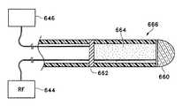
- a conduitcould, for example, have distal and proximal ends with a wall defining a lumen extending between the ends.
- the conduitcould have, for example, a porous wall permitting the exchange of gasses through the wall.
- the conduitmay, for example, be comprised of a material such as elastomers, polymers, metals, metal alloys, shape memory alloys, shape memory polymers, or any combination thereof.
- a variation of the inventionincludes an expandable conduit, either one that is self-expanding, or one that expands in diameter in relation to any applied radial, or axial force.
- the conduitmay be expanded into an opening of the natural airway upon the inflation of a balloon.
- a variation of the conduitmay include the use of flanges or anchors to facilitate placement of the device within an airway.
- Another variation of the conduitincludes placing a one-way valve within the conduit.
- Another variationincludes using a self cleaning mechanism within the conduit to clear accumulating debris.
- the inventionincludes the method of feeding a guidewire to a site within the lung, advancing a conduit to the site using the guidewire, and placing the conduit within the lung tissue at the site.
- the methodmay include inserting an access device, such as a bronchoscope, within airways of the lung to locate a site within the lung for creation of the collateral channel.
- the access devicecould also be used as an access device so that the required devices may be introduced to the site.
- a catheter having a conduit attached theretomay be advanced over the guide-wire for insertion of the conduit within the collateral channel.
- the inventive conduitmay be, for example, removable or permanent.
- another variation of the deviceincludes a means for inserting the conduit within a collateral channel.
- the conduitmay be constructed to allow for passage of gasses through its wall, for example, the conduit may have a wall consisting of a braid.
- a variation of the conduitmay be located through an opening in a wall of an airway and engage both an inside and outside of the wall.
- Another variation of the conduitincludes a distal end having a porous member and a proximal end having a grommet member which engages an opening in a wall of the natural airway.
- Yet another variation of the implantfor example, comprises an expandable conduit-like apparatus which could bridge an opening within a wall of a natural airway.
- Another variationincludes the conduit-like apparatus having a cutting portion exterior to the device wherein expansion of the device pierces the wall of the natural airway and creates a collateral channel.
- conduits of varying cross-sectional areasmay be placed in various sections of the lung to optimize the effect of the collateral channels.
- Another variation of the inventionincludes the application of a cyano-acrylate, fibrin or other bio-compatible adhesive to maintain the patency of a collateral channel.
- the adhesivemay be used with or without the conduit described above.
- the adhesivemay be deposited within the collateral channel to maintain patency of the channel or to create a cast implant of the channel.
- the inventive actfurther includes the act of delivering medications such as steroids which have been shown to inhibit the healing process, bronchodilators, or other such drugs which aid in breathing, fighting infection, or recovery from the procedure. The steroids inhibit inflammation and then promote the stabilization of the created channel.
- Another variation of the inventive processincludes promoting the flow of gasses through under-utilized parenchymal inter-conduits, or bypassing restricted airways. It is also contemplated that the gaseous flow may be altered by, for example, making separate inspiratory and expiratory paths. Also, relieving pressure on the external wall of a natural airway may be accomplished to assist the natural airway by maintaining patency during the expiration cycle of the lung. Yet another variation includes creating collateral channels parallel to existing airflow paths, or the existing airflow paths may be increased in cross-sectional area.
- the inventionfurther includes a modified respiratory airway having an artificially created channel allowing gaseous communication between an exterior of the airway and an interior of the airway.
- the inventionmay include an endoscope or a bronchoscope configured to select sites and create collateral channels at those sites.
- An endoscope or a bronchoscopemay also be configured to deploy conduits within the collateral channels.
- Another variation of the inventionincludes sizing the device to fit within the working channel of a bronchoscope.
- the inventionalso includes methods for evaluating an individual having a diseased lung for a procedure to create collateral channels within an airway of the individual.
- the inventionfurther includes the method of determining the effectiveness of the procedure.
- the inventionfurther includes the act of teaching or providing instructions for any of the methods described herein or for using any of the devices describe herein.
- the inventionfurther includes the method of sterilizing any of the devices or kits described above.
- FIGS. 1A-1Cillustrates various states of the natural airways and the blood-gas interface.
- FIG. 1Dillustrates a schematic of a lung demonstrating a principle of the invention described herein.
- FIGS. 2A-2Cillustrate devices and methods for determining the degree of collateral ventilation within a lung.
- FIGS. 3A-3Pillustrate methods of and devices for creating a collateral opening within a natural airway.
- FIGS. 4A-4Billustrate a method of folding epithelial tissue through a collateral channel.
- FIGS. 5A-5Dillustrate devices for detecting blood vessels within tissue.
- FIGS. 5E-5Villustrates various devices for detecting blood vessels within tissue where the devices also include hole-making assemblies.
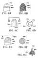
- FIGS. 6A-6Gillustrate various electrode configurations for the hole-making assemblies of the device.
- FIGS. 6H-6Jillustrates additional variations of the lens of the present invention.
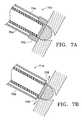
- FIGS. 7A-7Billustrate devices and methods for creating a collateral channel with a device having a hole-making assembly and also preserving the tissue surrounding the collateral channel.
- FIGS. 7C-7Dillustrate additional electrode configurations for use with a device of the present invention where the structure of the electrodes limits the possible depth of a collateral channel formed by the electrode.
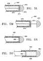
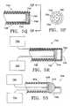
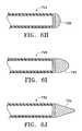
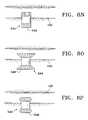
- FIGS. 8A-8Villustrate various configuration of implantable conduits.
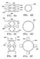
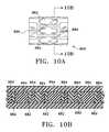
- FIGS. 9A-9U, 10 A- 10 B, and 11 A- 11 Cillustrate variations of conduits of the present invention.
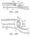
- FIGS. 12A-12Iillustrate variations of methods and devices for deployment of conduits of the present invention.
- FIGS. 13A-13Fillustrate methods of placing a conduit within tissue.
- FIGS. 1A-1CPrior to considering the invention, simplified illustrations of various states of a natural airway and a blood gas interface found at a distal end of those airways are provided in FIGS. 1A-1C.
- FIG. 1Ashows a natural airway 100 which eventually branches to a blood gas interface 102 .
- FIG. 1Billustrates an airway 100 and blood gas interface 102 in an individual having COPD. The obstructions 104 impair the passage of gas between the airways 100 and the interface 102 .
- FIG. 1Cillustrates a portion of an emphysematous lung where the blood gas interface 102 expands due to the loss of the interface walls 106 which have deteriorated due to a bio-chemical breakdown of the walls 106 .
- FIGS. 1A-1CAlso depicted is a constriction 108 of the airway 100 . It is generally understood that there is usually a combination of the phenomena depicted in FIGS. 1A-1C. More usually, the states of the lung depicted in FIGS. 1B and 1C are often found in the same lung.
- lung tissueis intended to include the tissue involved with gas exchange, including but not limited to, gas exchange membranes, alveolar walls, parenchyma and/or other such tissue.
- the collateral channelsallow fluid communication between an airway and lung tissue. Therefore, gaseous flow is improved within the lung by altering or redirecting the gaseous flow within the lung, or entirely within the lung.
- FIG. 1Dillustrate a schematic of a lung 118 to demonstrate a principle of the invention described herein.
- a collateral channel 112places lung tissue 116 in fluid communication with airways 100 allowing oxygen depleted/carbon dioxide rich air to directly pass out of the airways 100 .
- the term channelis intended to include an opening, cut, slit, tear, puncture, or any other conceivable artificially created opening.
- constricted airways 108may ordinarily prevent air from exiting the lung tissue 116 .
- conduits 200may be placed in the collateral channels 112 to assist in maintaining the patency of the collateral channels 112 . Therefore, it is not necessary to pierce the pleura to improve gaseous flow within the lungs.
- the inventionis not limited to the number of collateral channels which may be created, it is preferable that 1 or 2 channels are placed per lobe of the lung. For example, the preferred number of channels is 2-12 channels per individual patient.
- a variation of the inventive devicemay include an endoscope or a bronchoscope configured to locate a site for creating a collateral channel and create the collateral channel.
- Another variationincludes sizing the inventive device to fit within a working channel of an endoscope or a bronchoscope.
- any reference made to an endoscopeincludes the term bronchoscope.
- the inventionincludes assessing the degree of the collateral ventilation taking place in an area of a lung to select a site for creation of a collateral channel.
- the inventionmay include locating a site for creation of a collateral channel by visually examining an airway for dynamic collapse.
- One method of visual examinationincludes the use of a fiber optic line or camera which may be advanced into the lungs and through the airways.
- Also contemplated in the inventionis the addition of various agents to assist during imaging of the airways or lungs.
- a non-harmful gassuch as Xenon
- Another exampleincludes the use of inserting a fluid in the lungs to provide an improved sound transmission medium between the device and the tissue in variations of the invention using ultrasound, acoustic, or other imaging.
- Another variation of the inventionincludes methods and devices for triggering a collapse of the airway to determine the degree of collateral ventilation in the lung.
- One exampleincludes forcing a fluid, such as a gas, air, oxygen, etc., through the airway and into the air sacs.
- the pressureis reduced in the airway.
- One example of how pressure is reduced in the airwayincludes evacuating the air in a direction opposite to the air sacs. Constriction of the airway given a drop in pressure may be an indication of collateral ventilation of the lung in that region.
- FIG. 2Aillustrates a method and device 212 for causing collapse of the airway wall 100 .
- the device 212includes a fluid delivery member 214 located at a distal end of the device 212 .
- the fluid delivery member 214is configured to deliver a volume of fluid through the airway 100 and into an air sac (not shown).
- the device 212may also comprise a probe 216 configured to collect data within the lung.
- the probe 216may also simply consist of a channel that transmits signals outside of the lung.
- the fluid delivery member 214 and the probe 216may not be separate channels.
- the device 212may, but does not necessarily, have an occlusion member 218 designed to isolate a section of the airway 100 between the occlusion member 218 and the air sacs (not shown).
- the occlusion member 218which forms a seal against the airway 100 walls, may provide a partially closed system allowing a more effective search for collateral ventilation between the air sacs (not shown.)
- the devicedelivers a burst of fluid, through the fluid delivery member 214 and subsequently uses the probe 216 to measure characteristics such as pressure, flow, or return volume to determine the degree of collateral ventilation.
- the term fluidis intended to include, air or a gas, such as oxygen, etc. For example, if the air sacs are diseased (as shown in FIG.
- the forced fluidwill escape/disperse through another air sac due to the collateral ventilation of the air sacs.
- the probe 216may fail to record any increase in pressure, volume, flow, or any other characteristic of the fluid at the site.
- Another variation of the inventionincludes using the fluid delivery member 214 to add or remove fluid distally to the occluded segment and using the probe 216 to monitor flow or pressure changes in the area. For example, if after adding/removing fluid the pressure in the occluded segment fails to build/drop, the assumption may be made that the gas is being collaterally vented through diseased air sacs.
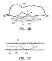
- FIG. 2Billustrates another variation of the invention.
- the device 220comprises a separated probe 216 and gas delivery member 214 .
- the fluid delivery member 214is configured to pass through a wall of the airway 100 so that fluid may be directly forced into, or pulled out of an air sac 102 .
- FIG. 2Cillustrates yet another variation of the invention.
- the device 222may have at least one fluid exchange passageway 224 .
- the device 222may force fluid into the airway 100 via the passageway 224 .
- fluidcan be pulled out via the passageway 224 , thus decreasing pressure distally to the device 222 .
- the decrease in pressurepermits fluid to flow out of the airway 100 and away from the air sac (not shown).
- a variation of the inventionmay include an expandable member 218 , such as a balloon, to create a seal against the airway 100 walls. Forming a seal may provide a partially closed system to search for collateral ventilation between air sacs (not shown.)
- observation of a collapsing airway 100may indicate a desired site for creation of a collateral channel.
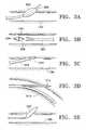
- FIGS. 3A-3Idepict various ways of providing openings in the airway wall which may be used as collateral air passageways.
- FIG. 3Aillustrates an airway 100 having a piercing member 300 and a dilation member 302 .
- the piercing member 300makes an incision (not shown) in the airway 100 wall.
- the piercing member 300is advanced into the wall so that a dilation member 302 can expand the incision to thereby provide a collateral channel.
- the dilation member 302is depicted as a balloon.
- One variation of the inventionincludes filling a balloon with a heated fluid as the balloon dilates the tissue to form the collateral channel. Use of a heated balloon allows the transfer of heat to the collateral channel for modifying the healing response.
- the dilation membermay be an expanding wedge (not shown) or other similar device.
- FIG. 3Bshows a cutting device 304 and an airway 100 having an opening 306 cut from a wall.
- a flap 308is cut from the wall and is attached to an outside or an inside wall of the airway 100 .
- the flapmay be glued, using for instance, fibrin-based or cyano-acrylate-based glues or stapled to that wall.
- FIG. 3Cillustrates a cutter 304 making an incision 310 in a wall of the airway 100 .
- FIG. 3Dillustrates one example of placing the walls of the airway 100 in tension and inserting a blunt instrument 314 into the incision.
- the delivery device 312is flexible and may be shaped to the contour of an airway 100 to provide support for the blunt instrument 314 so that the instrument 314 can advance into the incision.
- the delivery device 312is also used to deliver a blunt instrument 314 which expands the original incision.
- the blunt instrument 314may have a hooked configuration as needed.
- FIG. 3Eshows the use of a balloon 320 to dilate a previously formed collateral channel in the airway wall 100 .
- This proceduremay be used variously with other mechanical, chemical, cryo-energy, thermal or RF based penetration systems to expand the size of that previously-formed opening.
- variations of the inventive device described herein using energy to create a collateral channelwill require a power supply to be coupled to the active heating element. For sake of convenience, the power supply is not always illustrated in the Figures.
- FIG. 3Fillustrates a variation of the device 322 having an RF electrode 324 .
- This variation of the inventionuses RF energy to create a collateral channel.
- the device 322may be mono-polar or bi-polar.
- the RF energy throughout this inventionis similar to that of a typical RF cutting probe operating between the 300 KHz-600 KHz range.
- FIGS. 3G-3Iillustrates additional variations of devices of the present invention used to create collateral channels.
- the devicesmay use RF energy, either monopolar or bipolar, or the devices may use light, infrared heat, or any of the other methods describe herein.
- the device 328has an electrode 324 located on a side of the device. This variation of the device 328 automatically limits the depth of the collateral channel as the body of the device 328 remains against an airway 100 wall while the electrode 324 creates a channel.
- FIGS. 3H and 3Iillustrates another variation of a device 330 of the present invention having an electrode 324 located on a front face of the device.
- FIG. 3Iillustrates a perspective view of the device 330 with an electrode on the front face 324 .
- the device 330may either have an electrode 324 disposed on a front surface of the device 330 or the device may comprise a conductive material with an insulating layer 332 covering the device 330 and leaving an electrode surface 324 exposed.
- the size of the electrodemay be selected based upon the size of the desired collateral channel.
- the device of the present inventionmay also be configured to limit the depth of the collateral channel.
- the inventionmay include a shoulder or stop 326 to limit the depth of the collateral channel.
- Another exampleincludes graduated index markings on a proximal end of the device or on the distal end so long as they are remotely detectable.
- Also contemplatedis the use of RF impedance measuring. In this example, the use of RF impedance may be used to determine when the device leaves the wall of the airway and enters the air sac or less dense lung tissue.
- FIG. 3Jillustrates another variation of a device 334 of the present invention adapted to create collateral channels.
- the device 334includes an elongate body 336 which may have a lumen extending therethrough.
- the device 334further includes a heating element 338 extending from the elongate body 336 .
- the heating element described herein for the variations of the inventionmay be the type which actually generates heat in the element, such as, for example, a resistive heating element.
- the heating element described herein for the variations of the inventionmay be the type which actually generates heat directly within the tissue, for example, an RF electrode.
- the heating element of the present inventionshall have a heating surface located on the front surface of the heating element that is adapted to minimize heat in a radial direction from the heating element.
- the heating elementwill preferably be a cone, hemispherical, or similar member that is shallow in depth.
- the heating surfacewill have a depth (as illustrated by depth 341 in FIG. 3J) which is less than the diameter of the heating surface.
- the depthcould be less than the radius of the heating surface.
- the heating element 338 shown in FIG. 3Jincludes a heating surface 340 which is located over the front surface of the heating element 338 .
- the heating element 334may be any type of heat generating device described herein and is coupled to its respective power supply.
- the heating element 338comprises an RF electrode.
- the heating element 338is coupled to an RF generator (not shown).
- a variation of the deviceincludes a heating element which extends through the lumen of the elongate member. The heating element may extend throughout the elongate member or it may extend partially into the elongate member.
- the variation of the devices described hereinmay also include insulating surfaces.
- the device 334may have at least one insulating surface 342 located adjacent to the heating surface 340 .
- the insulating surface 342shields tissue from heat generated by the heating element 338 as the heating element 338 creates a collateral channel in tissue.
- the insulating surfaces described hereinmay be configured to shield tissue from heat generated by the heating element, or, the insulating surface may prevent heat from being generated in the tissue which is adjacent to the insulating surface (e.g., in an RF hole-making device).
- Each of these materialsis selected to have sufficient properties (e.g., low thermal conductivity, non-conductive, etc.).
- An insulating surfacemay comprise a ceramic material, such as alumina oxide, zirconia oxide, silicon nitride, silicate, etc.
- the insulating surfacemay also comprise a plastic tubing such as Nylon, polyimide, PTFE, Pebax, etc.
- Other examplesinclude insulating surfaces comprising, for example, an epoxy, or a bio-compatible coating such as paralene.
- the insulating surfacemay comprise a combination of the above listed materials. As discussed above, it is noted, that the device may be used without an insulating surface 342 .
- the device 334may further include a shoulder 344 located on the elongate body 336 and proximate to the heating element 338 .
- the shoulder 344is configured to expand to a diameter greater than a diameter of the elongate body 336 . Accordingly, the shoulder 334 serves as a stop or depth limiter for the device 334 as it creates a collateral channel.
- the shoulder 344comprises a balloon, which has a reduced profile (illustrated) and an expanded profile.
- FIG. 3Killustrates the balloon 344 in the expanded profile.
- the maximum diameter of a shoulder used in any variation of the invention described hereinmay vary depending upon the application. Currently, it is believed that a shoulder should be greater than 3 mm in diameter.
- the balloonmay be constructed from silicone, urethane, or other such materials.
- the elongate member of the variations describe hereinmay be comprised of a nylon, polyethylene, polycarbonate, etc., or a combination thereof.
- a variation of the device of the present inventionmay have a shoulder 344 comprised of other than a balloon, but is simply a structure which has a diameter greater than a diameter of a heating element on the device.
- the shoulder 344would not be adjustable in a radial direction from the elongate member 336 .
- FIG. 3Lillustrates another variation of a device 346 of the present invention adapted to create collateral channels.
- the device 346includes an elongate body 348 which may have a lumen extending therethrough.
- the device 346further includes a heating element 338 extending from the elongate body 348 .
- the heating element 338includes a heating surface 340 which may be located over the front surface of the heating element 338 .
- the heating element 338may be any type of heat generating device described herein and is coupled to its respective power supply.
- the heating element 338comprises an RF electrode. In such a case, the heating element 338 is coupled to an RF generator (not shown).
- the variation of the device 346 illustrated in FIG. 3Lmay also includes an insulating surface 342 located adjacent to the heating surface 340 .
- the insulating surface 342shields tissue from heat generated by the heating element 338 as the heating element 338 creates a collateral channel in tissue.
- the device 346 of FIG. 3Lfurther includes a shoulder 350 located on the elongate body 348 and proximate to the heating element 338 .
- the shoulder 350is configured to expand to a diameter greater than a diameter of the elongate body 348 allowing the shoulder 350 to serve as a stop or depth limiter for the device 346 as it creates a collateral channel.
- the shoulder 350is comprised of a plurality of hinged members 352 each of which is adapted to expand in diameter from the expandable member 348 .
- the hinged members 352each have a living hinge 354 which allows the hinged members 352 to assume an expanded or reduced profile.
- the hinged members 352expand away from the elongate member 348 given relative movement between the elongate member 348 and the heating element 338 .
- the heating element 338may be pulled in a proximal direction against the elongate member 348 causing the insulating surface 342 to force the hinged members 352 outwardly.
- the shoulder 350assumes an expanded profile.
- the hinged members 352are illustrated as being parallel to the lumen of the elongate member 348 , the invention is not limited as such.
- the number of hinged members 352is not limited to that which is illustrated. It is contemplated that variations of the inventive device may include 2 or more hinged members.
- a devicemay have a gap between the heating element and the elongate member such that the insulating surface is against or within the elongate member.
- the devicemay be designed to have a pre-determined gap between the insulating surface and the elongate member.
- FIGS. 3N-3Pillustrate another variation of the inventive device which is adapted to create collateral channels.
- the heating element 338is moveably located within an elongate member 360 .
- At least a portion of the lumen of the elongate member 360has a reduced opening 362 which is smaller than a diameter of the heating element 338 .
- a distal end of the elongate member 360may be radially adjustable to permit the heating element 360 to move in and out of the lumen.
- the front surface of the elongated member 360functions as a shoulder 364 when the heating element 338 extends from the front of the elongated member 360 .
- the distal end of the elongated member 360may be remotely actuated to expand, or, the distal end may be biased to expand outwardly. In the latter case, the distal end may be restrained, for example, by an outer tubular member 366 .
- the outer tubular member 336may also be used to reduce the diameter of the distal end to close against the heating element 338 , as shown in FIG. 3 P.
- the distal end of the elongated member 360may be a continuous tubular structure which expands in diameter, or it may be a tubular structure that divided into any number of portions which permit the radial expansion of the distal end.
- FIG. 3Nillustrates a front view of the device of FIG.
- the elongated member 360is divided into four portions 368 so that it may be radially adjustable. It is understood that the number of portions 368 illustrated are merely exemplary, as the number may be varied as needed. Furthermore, the elongated member 360 may not be divided into any such portions 368 and instead may be an expandable elastic member comprised of, for example: silicone, urethane, etc.
- the inventionalso includes creating a collateral channel by making a single or a series of incisions in an airway wall then folding back the cut tissue through the collateral channel.
- This procedureallows the surface epithelium which was previously on the inside of the airway wall to cover the walls of the newly formed collateral channel.
- promoting growth of the epithelium over the walls of the collateral channelprovides a beneficial healing response.
- the incisionmay be created by the use of heat or a mechanical surface.
- FIG. 4Aillustrates a section of an airway 100 having several incisions 356 forming a number of sections 358 of airway wall tissue the airway 100 .
- FIG. 4Billustrates the sections or flaps 358 of the airway wall folded through the collateral channel 112 .
- any number of incisions 358may be made to form any number of sections 358 of airway wall tissue as desired.
- a plus-shaped incisionwould result in four sections of tissue that may be folded through a channel.
- the sections 358may be affixed with a suture material, an adhesive, or the sections 358 may simply be inserted into surrounding tissue to remain folded through the collateral channel 112 .
- Another variation of the deviceincludes safety features such as probes to determine the presence of blood. If a probe indicates that a blood vessel is contacted or penetrated, a signal is sent which prevents the channel making device from causing further harm to the vessel. Such a feature minimizes the risk of inadvertently puncturing a blood vessel within the lungs.
- Another variation of the inventionincludes methods and devices for determining whether a blood vessel is in proximity to a potential site. Making this determination prior to creating the channel is advantageous as the risk of puncturing a blood vessel is minimized. It is important that the devices of the present invention do not ‘wander’ resulting in the creation of a collateral channel at a distance from the area originally searched. Such an occurrence may compromise a blood vessel (e.g., puncture, rupture, or otherwise open the blood vessel) even though the step of detecting the location indicated the absence of a blood vessel. In those cases, a device having a stiffer wall provides added benefits. Accordingly, the devices must be flexible to navigate to a target site, yet once they reach the target site the device should be configured to minimize subsequent movement.
- a blood vessele.g., puncture, rupture, or otherwise open the blood vessel
- the present inventionincludes the use of a device which is able to detect the presence or absence of a blood vessel by placing a front portion of the device in contact with tissue.
- One variation of the inventionincludes the use of Doppler ultrasound to detect the presence of blood vessels within tissue. It is known that sound waves at ultrasonic frequencies travel through tissue and reflect off of objects where density gradients exist. In which case the reflected signal and the transmitted signal will have the same frequency. Alternatively, in the case where the signal is reflected from the blood cells moving through a blood vessel, the reflected signal will have a shift in frequency from the transmitted signal. This shift is known as a Doppler shift. Furthermore, the frequency of the signals may be changed from ultrasonic to a frequency that is detectable within the range of human hearing.
- the ultrasound Doppleroperates at any frequency in the ultrasound range but preferably between 2 Mhz-30 Mhz. It is generally known that higher frequencies provide better resolution while lower frequencies offer better penetration of tissue. In the present invention, because location of blood vessels does not require actual imaging, there may be a balance obtained between the need for resolution and for penetration of tissue. Accordingly, an intermediate frequency may be used (e.g., around 8 Mhz).
- a variation of the inventionmay include inserting a fluid into the airway to provide a medium for the Doppler sensors to couple to the wall of the airway to detect blood vessels. In those cases where fluid is not inserted, the device may use mucus found within the airway to directly couple the sensor to the wall of the airway.
- FIG. 5Aillustrates a variation of a device 600 adapted to determine the presence of blood vessels as previously mentioned.
- the device 600includes a flexible elongate member 604 having a transducer assembly 606 , at least a portion of which is located adjacent to a distal end of the elongate member 604 .
- the elongate member 604is illustrated as having a lumen, the elongate member 604 may also be selected to be solid, or the elongate member 604 may have a support member (not shown) such as a braid to increase the strength and/or maneuverability of the device.
- the transducer assembly 606is adapted to generate a source signal and receive a reflected signal. It may use a single transducer or multiple transducers. For example, at least a first transducer may be used to generate a signal and at least a second transducer may be used to receive the signal.
- the transducer or transducersmay comprise a piezo-ceramic crystal.
- a single-crystal piezo (SCP)is preferred, but the invention does not exclude the use of other types of ferroelectric material such as poly-crystalline ceramic piezos, polymer piezos, or polymer composites.
- the substratetypically made from piezoelectric single crystals (SCP) or ceramics such as PZT, PLZT, PMN, PMN-PT; also, the crystal may be a multi layer composite of a ceramic piezoelectric material. Piezoelectric polymers such as PVDF may also be used.
- the transducer or transducers usedmay be ceramic pieces coated with a conductive coating, such as gold.
- conductive coatingsinclude sputtered metal, metals, or alloys, such as a member of the Platinum Group of the Periodic Table (Ru, Rh, Pd, Re, Os, Ir, and Pt) or gold. Titanium (Ti) is also especially suitable.
- the transducermay be further coated with a biocompatible layer such as Parylene or Parylene C. The transducer is then bonded on the lens. A coupling such as a biocompatible epoxy may be used to bond the transducer to the lens.
- the transducer assembly 606communicates with an analyzing device 602 adapted to recognize the reflected signal or measure the Doppler shift between the signals. As mentioned above, the source signal may be reflected by changes in density between tissue.
- the reflected signalwill have the same frequency as the transmitted signal.
- the reflected signalhas a different frequency than that of the source signal.
- This Doppler effectpermits determination of the presence or absence of a blood vessel within tissue.
- the analyzing device 602may alternatively be incorporated into the device 600 .
- the transducer assembly of the inventionis intended to include any transducer assembly that allows for the observation of Doppler effect, e.g., ultrasound, light, sound etc.
- the 5Aincludes a transducer assembly 606 comprising an ultrasound transducer 608 and an acoustic lens 610 that is adapted to refract and disperse a source signal over an outer surface of the lens 610 .
- the lens 610is designed such that it interferes and redirects the signals in a desired direction.
- the lens 610may be comprised of materials such as dimethyl pentene (plastic-TPX), aluminum, carbon aerogel, polycarbonate (e.g., lexan), polystyrene, titanium, etc. It also may be desirable to place an epoxy between the lens 610 and the transducer 608 . Preferably, the epoxy is thin and applied without air gaps or pockets.
- the density/hardness of the epoxyshould provide for transmission of the signal while minimizing any effect or change to the source signal.
- the configuration of the transducer assembly 606permits the lens 610 to disperse a signal over a substantial portion of the outer surface of the lens 610 .
- the lens 610also is adapted to refract a reflected signal towards the transducer 608 . Accordingly, given the above described configuration, the device 600 of FIG. 5A will be able to detect vessels with any part of the lens 610 that contacts tissue (as illustrated by the line 612 - 612 .)
- the lens 610is illustrated as being hemispherical, as described below, the lens 610 may have other shapes as well.
- FIG. 5Billustrates another variation of the device 614 having a hemispherical shaped ultrasound transducer 618 affixed to an end of a flexible elongate member 616 .
- the transducer 618communicates with an analyzing device (not shown) to measure the Doppler effect to determine the location of a blood vessel.
- FIG. 5Cillustrates another variation of the device 620 including a transducer assembly 622 , at least a portion of which is located adjacent to a distal end of the elongate member 628 .
- the transducer assembly 622includes a flat ultrasound transducer 626 , and a cone or wedge-like acoustic mirror 624 .
- the mirror 624is adapted to reflect the signal over an area 360° around the device. The angle ⁇ of the mirror may be varied to optimally direct the signal as needed.
- FIG. 5Dillustrates a variation of a device 630 of the present invention further comprising a joint 632 to articulate an end of the device either to make sufficient contact with an area of tissue to be inspected for the presence of a blood vessel, or to navigate within the body to access the area to be inspected.
- the variations of the invention described hereinmay also be adapted to use ultrasound energy, for example, high energy ultrasound, to produce openings in or marks on tissue.
- ultrasound energyfor example, high energy ultrasound
- the transducer assembly and acoustic lensalso functions as a hole-making or site marking device.
- use of ultrasound in a low power operationpermits the detection of a blood vessel and location of a site for a collateral channel.
- Using the same device and switching the operation of the device to a high power ultrasoundpermits the use of the ultrasound to create a collateral channel.
- FIG. 5Eillustrates a variation of a device 632 comprising a transducer assembly 634 connected to a flexible elongate member 636 .
- the transducer assembly 634comprises a first transducer 641 , a second transducer 642 , and an acoustic lens 640 .
- one transducermay transmit a signal while the other receives a signal.
- both transducers 641 , 642may simultaneously transmit and receive signals. It is intended that any combination of using the transducers to send and receive signals is contemplated.
- the device 632also includes a hole-making assembly 638 for creating a channel in tissue.
- FIG. 5Eillustrates the hole-making assembly 638 as an RF wire-like member.
- the device 632is connected an RF generator 644 as well as an analyzing device 646 which is adapted to measure the Doppler shift between the generated and reflected signals.
- FIG. 5Fillustrates the device 632 of FIG. 5E where the hole-making assembly 638 is retracted within the device 632 , in this case within the elongated member 636 .
- FIG. 5Gillustrates another variation of a device 648 where a hole-making assembly 650 is exterior to a transducer assembly 606 .
- the hole-making assembly 650may be either an RF device or a mechanical device that simply cuts the tissue.
- the hole making assembly 650can be a hypotube placed over the transducer assembly 606 .
- the transducer assembly 606may be moveable within the hole-making assembly 650 , or the hole-making assembly 650 may be moveable over the transducer assembly 606 . In either case, the transducer assembly 606 may be advanced out of the hole-making assembly 650 to determine the presence of a blood vessel.
- FIG. 5Hillustrates a view taken along the line 5 H in FIG. 5 G.
- FIG. 5Iillustrates another version of a device 652 of the present invention wherein the device has a transducer assembly 654 with an opening 658 through which a hole-making assembly 656 may extend.
- FIG. 5Jillustrates the hole-making assembly 656 extended through the transducer assembly 654 .
- the hole-making assembly 656may comprise RF electrodes or needle-like members which puncture the tissue to create the channels.
- FIG. 5Killustrates a variation of a device 666 of the present invention where a tip 660 of the device has a conductive portion allowing the tip to serve as both an acoustic lens and an RF electrode.
- the tip 660is connected to an RF generator 644 for creating channels within tissue and a transducer 662 is placed in communication with an analyzing device 646 that is adapted to measure the Doppler shift between generated and reflected signals.
- the tip 660is separated from the transducer 662 , but both the tip 660 and transducer 662 are in acoustic communication through the use of a separation medium 664 .
- the separation medium 664transmits signals between the tip 660 and the transducer 662 .
- the spacing of the transducer 662 from the tip 660serves to prevent heat or RF energy from damaging the transducer 662 . It is intended that the spacing between the transducer 662 and tip 662 shown in the figures is for illustration purposes only. Accordingly, the spacing may vary as needed.
- the separation mediummust have acceptable ultrasound transmission properties and may also serve to provide additional thermal insulation as well. For example, an epoxy may be used for the separation medium.
- FIG. 5Lillustrates a variation of a device 680 of the present invention wherein the transducer assembly 670 comprises a tip 672 , an ultrasound coupling medium 674 , a transducer 676 , and an extension member 678 .
- the tip 672 of the deviceserves as an acoustic lens and also has conductive areas (not shown) which serve as RF electrodes.
- the tip 672may extend from the device 680 and separate from the transducer 676 . Separation of the tip 672 protects the transducer 676 from heat or RF energy as the tip 672 creates a channel in tissue.
- the extension member 678may serve as a conductor to connect the tip 672 to an RF energy supply (not shown).
- the tip 672 of the device 680When the tip 672 of the device 680 is being used in an ultrasound mode, the tip 672 may be coupled to the transducer 676 via the use of an ultrasound coupling medium 674 .
- Any standard type of ultrasound gel materialmay be used, also highly formable silicone may be used. It is desirable to use a fluid boundary layer (such as the gel) which may be permanent or temporary. In those cases where the boundary layer is temporary, subsequent applications of the boundary layer may be necessary.
- FIG. 5Nillustrates another variation of a device 682 of the present invention having a tip 684 and transducer 686 that are separable from each other.
- the tip 684may include conductive areas and serve as both an RF electrode (not shown) as well as an acoustic lens.
- the tip 684may be separable from the transducer 686 when creating a channel to protect the transducer 686 from heat or RF energy.
- the tip 684may be placed in contact with the transducer 686 for operation in an ultrasound mode, or the device 682 may contain a separation medium 688 which permits acoustic coupling of the transducer 686 with the tip 684 when separated.
- FIG. 5Qillustrates another variation of the inventive device 740 which is able to detect the presence or absence of a blood vessel using Doppler ultrasound and which is also able to create collateral channels within the lung tissue.
- the deviceincludes a transducer adapted to generate a source signal and receive a reflected signal with a portion of the assembly located adjacent to the distal end of the elongate member 748 .
- the transducer assemblymay include at least one ultrasound transducer 742 and a lens 744 which enables the transmission and detection of a signal over a tip of the device 740 .
- the device 740further includes at least one heating element 746 located at a distal end of the lens 744 . The heating element permits the device to create collateral channels.
- the heating elementpermits the device to create collateral channels.
- the heating element 746comprises a plurality of openings 750 which allow for passage of ultrasound signals through the heating element 746 . Accordingly, the device 740 may use the transducer assembly to confirm the absence of a blood vessel at a particular site, and then use the heating element to create a collateral channel.
- FIG. 5Pillustrates a front view of the device 740 of FIG. 5P further illustrating the heating element 746 with a number of openings 750 .
- the number of openings 750 on a heating elementis not limited to that shown.
- the heating element 746may comprise a mesh having a plurality of openings.
- FIG. 5Rillustrates a variation of the inventive device wherein the transducer assembly is moveable within a lumen of the elongate member 748 . As described elsewhere herein, the transducer assembly may be moved when the heating element 746 is activated to create collateral channels.
- FIG. 5Rdepicts the device 740 as being connected to a power supply 752 and to an ultrasound controller device 754 .
- FIG. 5Sillustrates another variation of a device of the present invention where the transducer assembly comprises at least one transducer 608 and an acoustic lens 610 that is adapted to refract and disperse a source signal over an outer surface of the lens 610 .
- the lens 610is designed such that it interferes and redirects the signals in a desired direction.
- the transducer assemblyis coupled to an ultrasound controller device 754 .
- the device 756further includes a heating element 758 located distally of the lens 610 .
- the heating element 758is coupled to a power supply 752 .
- the heating element 758is illustrated as extending into the elongate member 604 of the device 756 , the device is not limited as such.
- the heating element 758may be configured in a “U” shape. With this configuration, after the device 756 penetrates tissue, rotation of the device 756 permits coring of the tissue to create a collateral channel. However, the heating element 758 may be configured in other shapes as needed.
- FIGS. 5T-5Villustrate another variation of the inventive device 770 which is adapted to detect the presence or absence of a blood vessel using Doppler ultrasound and which is also able to create collateral channels within the lung tissue.
- the device 770includes a detection device 600 adapted to determine the presence of blood vessels, as discussed above, is moveably located within an elongate member 762 . At least a portion of the lumen of the elongate member 762 has a reduced opening 764 which is smaller than a diameter of the detection device 600 .
- the detection devicemay be any detection device described herein.
- a distal end of the elongate member 762may be radially adjustable to permit movement of the detection device 600 in and out of the lumen.
- a heating element 760is placed on a distal end of the elongate member 762 . Accordingly, when the detection device 600 is advanced out of the elongate member 762 , the detection device 600 may determine the presence or absence of a blood vessel. Once a suitable location is found for the creation of a collateral channel, the detection device 600 is retracted into the elongate member 762 , thereby positioning the heating element 760 to create a collateral channel.
- the detection device 600may be moved proximally to minimize the possibility of any damage resulting from the generated heat.
- the elongate membermay contain a shoulder to limit the depth of the collateral channel.
- the detection device 600may be configured to create a collateral channel via ultrasound energy. In such a case, no heating element is required and the expandable distal end of the elongate member 762 may serve as a shoulder to limit the depth of the collateral channel. In any case, as shown in FIG. 5U, when the device 770 is advanced through the airways of a lung, the detection device 600 may remain within the elongate member 762 .
- the distal end of the elongated member 762may be remotely actuated to expand, or, the distal end may be biased to expand outwardly. In the latter case, the distal end may be restrained, for example, by an outer tubular member 766 .
- the outer tubular member 766may also be used to reduce the diameter of the distal end to secure against the detection device 600 , as shown in FIG. 5 V.
- the distal end of the elongated member 762may be a continuous tubular structure which expands in diameter, or it may be a tubular structure that divided into any number of portions 768 which permit radial expansion of the distal end.
- FIG. 5Uillustrates a front view of the device of FIG.
- FIGS. 6A-6Fillustrate variations of RF electrode tip 690 configurations for use with the present invention.
- the electrodesmay be placed around a circumference of a tip, longitudinal along a tip, spirally along a tip, or a combination thereof.
- the electrodes 692 , 694may be used with a device having an acoustic lens or the electrodes may be employed solely as an RF hole-making device. While the variations illustrated in FIGS. 6A-6F show bipolar RF devices, the invention may also use a single electrode (monopolar.)
- the tip 690may contain a first electrode 692 separated from a second electrode 694 by an electrical insulator 696 (e.g., ceramic, or plastic insulator).
- an electrical insulator 696e.g., ceramic, or plastic insulator
- FIG. 6Gillustrates a co-axial variation of a bi-polar RF tip having a first electrode 692 , a second electrode 694 , and an insulator 696 .
- FIGS. 6H-6Jillustrates additional variations of the lens of the present invention.
- FIG. 6Hillustrates a device 724 with an acoustic lens 726 having an oblate spheroid shape.
- FIG. 6Iillustrates a device 728 with an acoustic lens 730 having a prolate spheroid shape.
- FIG. 6Jillustrates a device 732 having a conical-shaped acoustic lens 734 .
- These variationsare only intended to illustrate variations of the lens. It is contemplated that the shape of a lens may not follow a mathematical description such as conical, prolate, oblate or hemispherical.
- the design of the shaperelates to the distribution pattern of the signal over the lens. The shapes can affect the distribution pattern by making it wider or narrower as needed. In any case, the lens is of a shape that provides coverage over the front face of the device.
- FIG. 7Aillustrates a variation of the invention where a device 700 includes a heat-sink member 702 .
- the heat-sink member 702may preserve surround tissue during creation of the collateral channel.
- the heat-sink member 702may be a section of conductive material or a balloon.
- the heat-sink member 702may be in fluid communication with a lumen 704 that provides a fluid, such as saline, that conducts heat away from the area surrounding the channel.
- FIG. 7Billustrates another variation of a device 710 having a fluid delivery assembly 706 which assists in preserving surrounding tissue while a channel is being created.
- the fluid delivery assembly 706may spray, mist, or otherwise apply fluid 708 to the area surrounding the channel.
- cooled salinemay be applied to the area to prevent excessive heating of the target area.
- FIG. 7Cillustrates a variation of an RF electrode 712 for use with the present invention.
- the electrode 712may be a protrusion extending from a conductive member 716 that is covered with an insulating material 714 .
- the electrode 716limits the depth of the channel due to the amount of material extending from the conductive member 716 .
- the conductive member 716may be connected to a source of RF energy (not shown) or may use another heating element (not shown).
- FIG. 7Dillustrates another variation of an electrode configuration.
- the electrodecomprises a spherical member 718 extending from an elongate member 722 .
- the electrode 718is retractable through the elongate member 722 by use of an actuator 720 .
- the actuator 720may be conductive and connected to a source of RF energy to conduct energy through the electrode 718 .
- the design of the electrode 718limits the depth of penetration of the electrode 718 while creating a channel in tissue.
- the electrodes described hereinmay also be used in conjunction with a device having a Doppler arrangement.
- a variation of the inventioncontemplates the delivery of drugs or medicines to the area of the collateral opening.
- a fibrin, cyano-acrylate, or any other bio-compatible adhesiveto maintain the patency of the opening.
- the adhesivecould be deposited within the collateral channel to maintain patency of the channel or to create a cast implant of the channel.
- the adhesivecould also coat the channel, or glue a flap to the wall of the airway.
- the use of a bioabsorbable materialmay promote the growth of epithelium on the walls of the conduit. For example, covering the walls of a channel with small intestine submucosa, or other bioabsorbable material, may promote epithelium growth with the bioabsorbable material eventually being absorbed into the body.
- FIG. 8Aillustrates an implant or conduit 500 placed within a natural airway 100 .
- the airway 100has a portion of its wall removed, thereby providing a collateral opening 112 within the airway 100 .
- the implant 500typically has a porous structure which allows gasses to pass between the airway and the channels 112 and into the lung. Moreover, the structure of the insert 500 also maintains patency of the airway 100 and the channel 112 .
- a conduit described hereinmay comprise a barrier layer which is impermeable to tissue. This aspect of the invention prevents tissue ingrowth from occluding the channel.
- the barrier layermay extend between the ends of the body or the barrier layer may extend over a single portion or discrete portions of the body of the conduit.
- FIG. 8Billustrates an conduit 500 having an expandable structure within an airway 100 .
- the conduit 500has a porous wall that allows the passage of gasses through the wall.
- the conduit 500is delivered via a delivery device 502 which may also contain an expandable member (not shown) which expands the conduit 500 .
- the conduitmay have piercing members 504 attached on an outer surface which enable the conduit 500 to create an incision within the airway 100 .
- FIG. 8Cillustrates the conduit 500 after being expanded by an expandable member 506 , e.g. a balloon device, an expandable mechanical basket, or an expandable wedge.
- an expandable member 506e.g. a balloon device, an expandable mechanical basket, or an expandable wedge.
- the conduit 500expands through the walls of the airway 100 at sections 508 .
- the conduit 500is lodged within the walls of the airway 100 .
- FIG. 8Dillustrates a grommet-like insert 503 where the lumen of the insert 503 extends longitudinally through the collateral channel.
- an expanding member 501e.g., a balloon, an expanding mechanical basket, or the like is used to secure the conduit 503 within the collateral channel.
- conduitshaving a length to diameter ratio approximately 1:1. However, this ratio may be varied as required.
- the cross-section of an implantmay be circular, oval, rectangular, elliptical, or any other multi-faceted or curved shape as required.
- the cross-sectional area of an implant 500may be between 0.196 mm 2 to 254 mm 2 .
- the conduitmay also be any device capable of maintaining a patent opening, e.g., a plug, that is temporarily used as a conduit and then removed after the channel has healed in an open position.
- a plugmay be a solid plug without an opening that is either bio-absorbable or removable. In such a case, the plug may be placed within an opening in tissue and allow the tissue to heal forming a collateral channel with the plug being ultimately absorbed into the body or removed from the body.
- the conduit 510comprises a cone 514 with a grommet 512 for attachment to a wall of the airway 100 .
- the cone 514may be porous or have other openings 516 to facilitate the passage of gas through the collateral channel. In the event that the distal opening of the cone become occluded, the porous cone permits the continued exchange of gasses between the collateral channel and the natural airway.
- the conduit 518may be configured in a ‘t-shape’ with a portion 520 of the conduit extending through the collateral channel.
- the conduit 518may be constructed to have a porous wall to allow gas exchange through the wall.
- the conduitmay be configured in a variety of shapes so long as a portion of the conduit extends through the collateral channel.
- the portionmay be formed into a particular shape, such as the ‘t-shape’ described above, or, the portion may be hinged so that it may be deployed within the channel. In such a case, a portion of a wall of the conduit may have a hinge allowing the wall of the conduit to swivel into a channel.
- conduit 522is constructed with a geometry that reduces the chance that the conduit 522 will migrate within the airway 100 .
- FIG. 8Hillustrates an example of a conduit 524 having an asymmetrical profile.
- the conduit 524may have a flange 526 at either or both ends of the body 528 .
- the flange 526may have a cone-like profile to facilitate placement within an airway.
- the asymmetrical profile of the conduit 524assists in preventing obstruction of the airway.
- FIG. 8Jillustrate a variation of the conduit 530 having a self-cleaning mechanism.
- the self cleaning mechanismis a floating ball bearing 532 .
- the ends of the conduit 530have a reduced diameter 534 which prevents the bearing 532 from escaping. As gas passes through the conduit 530 , the bearing 532 moves about the conduit 530 clearing it of debris.
- the shape of the bearing 532 and the size and shape of the reduced diameter 534may be varied to optimize the self-cleaning effect of the device.
- FIGS. 8K and 8Lillustrate another variations of a self-expanding conduit 536 .
- the conduit 536may be constructed from a flat material 538 having a spring or springs 540 .
- the conduit 536is formed by rolling the assembly.
- the spring 540provides an expanding force against the material 538 .
- the conduit 536may also be constructed so that the flat material 538 is resilient thus eliminating the need for springs 540 .
- FIG. 8Millustrates another variation of an expandable conduit 542 constructed from a braided material.
- the conduit 542may be constructed so that the diameter is dependent upon the length of the device 542 .
- the diameter of the device 542may decrease as the length is stretched, and the diameter may increase as the length of the device 542 is compressed.
- Such a constructionbeing similar to a ‘finger cuff’ toy.
- FIGS. 8N-8Pillustrate another variation of a grommet-type conduit.
- FIG. 8Nillustrates a conduit 544 having expandable ends 546 .
- the ends 546 of the device 544may flare outwards as illustrated in FIG. 5 P.
- FIG. 8Nillustrates another variation of the device 544 in which the ends 546 compress in length to expand in diameter.
- FIGS. 8Q and 8Rillustrate variations of a conduit having an anchor.
- the conduit 548has an anchor 550 at a distal end of a hollow plug 540 .
- the anchor 550may be tapered to facilitate entry into the airway 100 wall or may have another design as required.
- the anchor 550also contains ventilation openings 552 to facilitate gas exchange through the device.
- FIG. 8Rillustrates another variation of the device.
- FIG. 8Sillustrates a variation of a conduit 561 having flanges 563 at either end to assist in placement of the conduit within an airway wall (not shown).
- the ends of the conduit 565may be tapered to ease placement through a collateral channel.
- the conduithas an opening 565 to facilitate passage of air.
- the conduit 561may be constructed from a biocompatible material, such as stainless steel, or plastic.
- FIG. 8Tillustrates a variation of the invention having multiple openings for gas flow.
- the conduit 560has a first hollow end 564 which can extend through a wall of the airway 100 and a second hollow end 566 which can remain parallel to the airway 100 .
- This examplealso includes an opening 562 which allows gas to flow through the airway 100 .
- FIG. 8Uillustrates a variation of the device having a one-way valve 570 .
- the valve 570allows the conduit 568 to permit exhaust of the air sac but prevents the conduit 568 from serving as another entrance of gas to the air-sac.
- the valve 570may be placed at ends of the conduit or within a lumen of the conduit.
- the valve 570may also be used as bacterial in-flow protection for the lungs.
- FIG. 8Villustrates another variation of a conduit 572 .
- the conduit 572may be a sponge material, or constructed of an open cell material 574 , which allows air flow through the material.
- the conduit 572may have lumens 576 which allow flow through the conduit 572 .
- the conduit materialmay be selected such that it expands as it absorbs moisture.
- the sponge material/open cell materialmay be bio-absorbable to allow for temporary placement of the conduit 572 .
- FIGS. 9A-9Fillustrate another variation of a conduit 800 of the present invention.
- the conduit 800has a center section 802 having extension members 804 located at either end of the center section 802 .
- the center section 802 illustratedis tubular but may be of any other shape as needed for the particular application.
- the conduit of the inventionhas a passageway extending between the ends of the conduit suited for the passage of air.
- the variation of the conduit 800 illustrated in FIG. 9Ahas a center section 802 comprising a mesh formed from a plurality of ribs 806 .
- FIGS. 9A and 9Billustrate the conduit 800 in a reduced profile while FIGS. 9C and 9D illustrate the conduit 800 in an expanded profile after expansion of the center section 802 of the conduit 800 . As shown in FIGS.
- each free end 808 of each extension member 804is unattached to the center section 802 and is bendable about the respective end of the center section 802 to which it is attached. Accordingly, once a conduit 800 is placed within a collateral channel (not shown), the extension members 804 are bent about the end of the center section 802 and form a cuff or grommet which assists in keeping the conduit 800 within a collateral channel. Accordingly, the cross section and number of extension members 804 located about either end of the conduit 800 may be selected as necessary to assist in placement and securing of the conduit 800 within a channel.
- the conduits described hereinmay have a fluid-tight covering, as discussed below, about the center section, the extension members, or the entire conduit. Also, the conduit may be designed to limit a length of the center section to less than twice the square root of a cross sectional area of the center section when the center section is in the expanded profile.
- FIGS. 9G-9Iillustrates another variation of a conduit 812 for use with the invention.
- the conduit 812is formed from a rolled sheet of material 810 .
- the rolled sheet 810may be heat treated to preserve the shape of the conduit 812 or the sheet 810 may simply be rolled to form the conduit 812 .
- the sheet of material 810comprises a shape-memory alloy, it is desirable to process the material 810 so that it exhibits super-elastic properties at or above body temperature.
- FIG. 9Gillustrates a variation of extension members 820 for use with a conduit (not shown) of the present invention.
- the extension members 820have an attachment 822 between adjacent extension members 820 .
- FIG. 9Hillustrates the extension members 820 as the conduit (not shown) is expanded and the extension members 820 are bent on the conduit.
- the attachment 822assists in preventing the extension members 820 from deviating from a preferred position.
- the conduit 826may have cut or weakened sections 824 to facilitate expansion of the conduit 826 and bending of the extension members in a desired manner (as shown by the section of 828 ).
- FIGS. 9J-9Killustrate various additional cross sectional designs of conduits.
- FIG. 9Jillustrates a possible conduit design 830 having extension members 834 attached to a center section 832 .
- FIGS. 9K and 9Lillustrate additional variations of conduit designs. As illustrated in FIGS. 9K and 9L, the extension members 840 , 846 and center sections 838 , 844 are designed to form a diamond pattern upon expansion of the conduit.
- FIG. 9Kfurther illustrates a variation of an extension member 840 having an opening 841 to facilitate tissue ingrowth and thereby secures placement of the conduit.
- FIG. 9Millustrates an expanded conduit 848 having the diamond pattern referred to above.
- the conduit 848also contains a fluid-tight barrier 851 on the center section 850 of the conduit 848 .
- fluid-tight barriermay be placed throughout a conduit.
- the extension membershave a diamond pattern construction, this construction assists in maintaining alignment of the extension members allowing for a preferred aligned expansion of the extension members.
- FIGS. 9N-9Oillustrate another variation of a conduit 860 of the present invention.
- the conduit design 854may have extension members 856 at only one end of the conduit 860 .
- the center section of the conduitmay comprise a body portion 858 .
- the conduit 860may have a covering about a portion of the conduit 860 . The covering may extend throughout the length of the conduit 860 or it may be limited to a portion of the conduit 860 .
- the conduit 860when expanded, the conduit 860 may form a reduced area 858 near the extension members 856 .
- the conduit cross section 854may be designed such that the a diamond pattern is formed upon expansion of the conduit 860 , as illustrated in FIG. 9 O.
- FIG. 9Pillustrates a sheet of material 810 having extension members 814 extending from either end of the sheet 810 .
- the sheet 810is illustrated to be solid, a conduit may be formed from a sheet having openings within the center section of the sheet.
- FIG. 9Qillustrates the conduit 812 where the rolled sheet 810 comprises a center section 818 of the conduit 812 and the extension members 814 from either end of the center section 818 .
- the sheet 810may be overlapped for a reduced profile and expanded into an expanded profile.
- FIG. 9Rillustrates a free end 816 of each extension member 814 as having been bent away from a central axis of the conduit 812 .
- the extension members 814 of the conduit 812may be bent away from a central axis of the conduit 812 up to 180° with respect to the central axis.
- the cross section and number of extension members 814 located about either end of the conduit 810may be selected as necessary to assist in placement and securing of the conduit 810 within a channel.
- the conduit 812 of FIG. 9Qcomprises a non-shape memory alloy
- the conduit 812will be actively mechanically expanded.
- the conduit 812may be pre-formed to assume a deployed shape which includes a grommet formed by extension members 814 and an expanded center section 818 , such as the shape illustrated in FIG. 9 R.
- the super-elastic conduit 812may be restrained or even rolled into the shape illustrated in FIG. 9 Q. Because the conduit 812 is formed of a super-elastic material, no plastic deformation occurs.
- the conduit 812may naturally resume its pre-formed, deployed shape.
- FIG. 9Sillustrates another variation of a conduit 862 having a first portion 864 and a second portion 866 and a passageway 868 extending therethrough.
- the first portion 864may be a conduit design as described herein.
- the first portion 864is configured to secure the conduit 862 to the airway wall 100 .
- the first portion 864may or may not have a center that is expandable.
- the walls of the first portion 864may be fluid-tight (either through design, or a fluid tight covering) to prevent tissue in-growth through the collateral channel.
- the first portion 864may be partially fluid-tight to facilitate tissue in-growth to improve retention of the conduit 862 to the airway wall 100 .
- the first portion 864should be designed to minimize tissue in-growth within the channel to prevent substantial interference with airflow through the conduit 864 .
- the walls of the second portion 866 of the conduitmay or may not be fluid-tight. If the second portion 866 is not fluid-tight, the larger area provides for improved airflow from lung tissue through the passageway 868 and into the airway.
- the second portion 866may also be designed to be partially fluid-tight to encourage airflow through the conduit 862 but reduce the probability of blockage of the conduit 862 .
- FIGS. 9T-9Uillustrate another variation of a conduit 870 .
- the conduit 870may be formed from a tube that is slit to form extension members at a first portion 872 and second portion 876 with a center section 874 between the portions.
- the conduit 870may be expanded as shown in FIG. 9U such that the first 872 and second 876 portions maintain the center portion 874 in a collateral channel in an airway wall.
- the center section 874may or may not be expandable.
- FIG. 9Uillustrates the second portion 876 of the conduit 870 to expand in its center
- the conduit 870may be designed in other configuration as well (e.g., expanded to have a larger diameter at an end opposite to the center section 874 .)
- a central aspect of this designis that the second portion 870 provides a large area in the lung tissue to permit a larger volume of air to pass from the lung tissue into the conduit 870 .
- This designhas an added benefit as the second portion 876 cannot be easily blocked by flaps of parenchyma tissue.
- a simple variation of the conduit 870may be constructed from a metal tube, such as 316 stainless steel, titanium, titanium alloy, nitinol, etc.
- the conduitmay be formed from a rigid or elastomeric material.
- the conduits described hereinmay be comprised of a metallic material (e.g., stainless steel), a shape memory alloy, a super-elastic alloy (e.g., a NiTi alloy), a shape memory polymer, a polymeric material or a combination thereof.
- the conduitmay be designed such that its natural state is an expanded state and it is restrained into a reduced profile, or, the conduit may be expanded into its expanded state by a variety of devices (e.g., a balloon catheter.)
- the conduit described hereinmay be manufactured by a variety of manufacturing processes including but not limited to laser cutting, chemical etching, punching, stamping, etc.
- the conduits described hereinmay be coated with an elastomer, e.g., silicone, polyurethane, etc.
- the coatingsmay be applied, for example, by either dip coating, molding, or liquid injection molding (for silicone).
- the coatingmay be a tube of a material and the tube is placed either over and/or within the conduit.
- the coating(s)may then be bonded, crimp, heated, melted, or shrink fit.
- the coatingsmay also be placed on the conduit by either solvent swelling applications or by an extrusion process.
- a coating ofmay be applied by either wrapping a sheet of PTFE about and/or within the conduit, or by placing a tube about and/or within the conduit and securing the tubes.
- FIGS. 10A-10BAnother variation of the invention is illustrated in FIGS. 10A-10B.
- a conduit of the present inventioncontains a filler material between the openings of the ribs or mesh.
- FIG. 10Aillustrates a partial plane view of a conduit 880 having a plurality of ribs or a mesh structure 882 as previously described.
- the conduit 880includes placing a filler material 884 between each of the ribs/opening of the mesh.
- a covering 886is then placed over the ribs/mesh 882 and filler material 884 .
- the covering 880encapsulates the structure of the conduit 880 and covers the outer surface of the conduit 880 and the interior wall of the lumen or passageway of the conduit 880 .
- FIG. 10Billustrates a partial sectional view of the conduit 880 of FIG. 10 A.
- FIG. 10Billustrates the mesh 882 with filler material 884 adjacent to the mesh 882 and an outer covering 886 encapsulating the mesh 882 and filler material 884 .
- the filler material 884 and covering 886may be placed entirely throughout a conduit. Alternatively, the filler material 884 and covering 886 may be placed partially over a conduit as needed. It is believed that the addition of filler material to a conduit of the present invention provides a uniform thickness of the covering which results in uniform and consistent stretching of the covering.
- Some various examples of filler materialare, for example, wax, silicone, and urethane.
- the coveringmay consist of, for example, silicone, urethane, or similar materials.
- FIGS. 11A-11Cillustrate another variation of a conduit 888 of the present invention.
- the conduitcomprises a continuous phase material 896 that is weak enough to expand but strong enough to keep a particular size and shape upon expansion of the conduit 888 .
- a continuous phase materialare polytetrafluoroethylene and polypropylene. These materials exhibit plastic deformation without exhibiting tears or breaches in their surfaces when expanded. These materials may be selected to have a properties (e.g., modulus, yield stress, etc.) which permit expansion of the conduit into a desired shape and retention of that shape.
- the conduitmay have weakened sections that permit the ends of the conduit to bend as desired.
- the wall thickness of the conduit 888may vary as illustrated. As shown in FIG. 11A, the wall thickness of the material 896 between the extension members 890 and the center section 892 may be less than a thickness of the wall section of the material 896 at the center section 892 . As illustrated, if an outwardly radial force is applied to the extension members 890 , such a configuration results in a higher bending stress at the area of reduced wall thickness 894 . As a result, and as illustrated in FIGS. 11B-11C, the extension members 890 expand in a predetermined manner.
- the number of and cross sectional area of the extension members on a conduitmay be selected as needed for the particular application.
- the extension membersmay be bent such that they anchor into the tissue thereby securing placement of the conduit.
- the extension members or the center sectionmay contain barbs or other similar configurations to better adhere to the tissue.
- the orientation of the extension membersmay vary as well.
- the extension membersmay be configured to be radially expanding from the center section, or they may be angled with respect to a central axis of the conduit.
- Another variation of the inventionincludes a radioactive conduit which inhibits or prevents the growth of tissue within the conduit.
- conduits of the current inventionhave been described to contain expandable center sections, the invention is not necessarily limited as such. Instead, the design of the conduit may require extension members on the ends of a conduit with a non-expandable center section.
- FIGS. 12A-12Dillustrate a conduit 900 of the present invention.
- the deployment of the conduit 900is intended to show an example of a possible means of deployment only.
- the inventive conduitmay be delivered at an angle via an articulating or jointed device, the conduit may be delivered on a device that is adapted to locate and create the collateral channel, or the conduit may be delivered on a device having other features as needed for the particular application.
- FIG. 12Aillustrates the conduit 900 being delivered to a collateral channel in an airway wall 114 via a delivery device (e.g., a balloon catheter 902 .)
- the conduit 900may be attached to the delivery device 902 using the natural resiliency of the conduit 900 .
- the conduit 900restrained in a reduced profile and may be removably affixed to the delivery device 902 using an adhesive, or a removable sleeve such as a heat shrink tube.
- the balloon catheter 902has several balloons including a distal balloon 904 , a proximal balloon 906 , and a center balloon (not illustrated in FIG. 12 A).
- FIG. 12 Aillustrates the conduit 900 being delivered to a collateral channel in an airway wall 114 via a delivery device.
- the conduit 900may be attached to the delivery device 902 using the natural resiliency of the conduit 900 .
- the conduit 900restrained in a reduced profile and may be removably af
- FIG. 12Billustrates the inflation of the distal 904 and proximal 906 balloons to situate the extension members 908 . Accordingly, the extension members 908 for a flange or collet about the airway wall 114 .
- the balloons 904 , 906may be inflated simultaneously, or in a desired sequence. In any case, deployment of the balloons 904 , 906 may serve to center the conduit 900 in the collateral channel.
- FIG. 12Cillustrates inflation of the center balloon 912 which causes expansion of the center section 910 of the conduit 900 .
- expansion of the center balloon 912causes release of the conduit 900 by release of the adhesive or breaking of the heat shrink tubing (not shown).
- the means of attachmentmay be bioabsorbable and remain in the body, or may remain affixed to the delivery device 902 and is removed with removal of the delivery device 902 .
- FIG. 12Dillustrates the conduit 900 affixed to the airway wall 114 after the delivery device 902 is removed from the site.
- FIGS. 12E and 12Fillustrate possible ways to manipulate a conduit 914 for placement in an airway wall 114 using a delivery device 916 .
- FIG. 12Eillustrates deployment of a delivery device 916 to place a conduit 914 within an opening in an airway wall 114 .
- the conduit 914may be placed over a balloon 918 (or other expandable section) of the delivery device 916 .
- FIG. 12Eillustrates deployment of a delivery device 916 to place a conduit 914 within an opening in an airway wall 114 .
- the conduit 914may be placed over a balloon 918 (or other expandable section) of the delivery device 916 .
- FIGS. 12E and 12Fillustrates deployment of the balloon 918 to place and expand the conduit 914 .
- a balloon 918serves several functions. The balloon 918 first expands and starts bending the extension members 920 . The balloon 918 continues to center the conduit 914 on the tissue and simultaneously begins to expand the conduit 914 and secures the conduit to the tissue.
- FIGS. 12G and 12Hillustrate additional variations of deployment devices.
- the deployment devices 922 , 926contain hour glass-shaped balloons 924 , 928 .
- the hour glass-shaped balloons 924 , 928contain an interior profile 923 .
- the conduitis placed on the balloon 924 , 928 .
- the conduit expansionmatches the interior profile 923 of the balloon 924 , 928 .
- the hour glass-shaped balloon 924 , 928may be used to set the angle and orientation of the expandable members of a conduit as well as the expansion of a center section of the conduit.
- FIG. 12Iillustrates another variation of an hour glass shaped balloon delivery device 930 .
- This variation of the hour glass shaped balloon 932is designed to expand extension members (not shown) of a conduit (not shown) at a particular angle 934 .
- the orientation of the balloon 932may be designed as needed to impart the desired angle to the extension members of the conduit.
- the balloons described hereinmay be constructed of polyethylene terephthalate (PET) or any other material which is used in the construction of balloon catheters.
- FIG. 13Aillustrates a method of placing a conduit within lung tissue.
- FIG. 13Aillustrates the advancement of an access device 940 into the airways 100 of a lung.
- the access device 940will have at least one lumen or working channel 942 .
- the access device 940will locate an approximate site 944 for creation of a collateral channel.
- a bronchoscope or other similar type of endoscopemay be used as the access device 940 .
- the access device 940is equipped so that the surgeon may observe the site for creation of the collateral channel.
- the method of placing a conduit within lung tissuemay be performed using non-invasive imaging techniques as well.
- the access device 940 as well as the other devices discussed hereinmay be configured for detection by the particular non-invasive imaging technique such as fluoroscopy, “real-time” computed tomography scanning, or other technique being used.
- FIG. 13Billustrates a blood vessel detection device 946 advanced through the channel 942 of the access device 940 towards the site 944 .
- the site 944is then inspected to determine whether a blood vessel is adjacent to the site. As discussed herein, it may be desirable to avoid blood vessels when creating a collateral channel.
- FIG. 13Cillustrates the creation of a collateral channel 112 by a hole-making device 948 .
- hole-making devices 948are disclosed throughout this specification.
- variations of this inventioninclude the use of devices which are equipped for detection and hole-making. Such devices are also disclosed throughout this specification.
- the device 948may be manipulated to a position that is optimal for creation of the collateral channel 112 .
- the access device or the hole-making devicemay be steerable. Such a feature may assist in the positioning of any of the devices used in the inventive method.
- it is desirable to create the collateral channelsuch that it is in fluid communication with an air-sac. The fluid communication allows for the release of trapped gasses from the hyperinflated lung.
- FIG. 13Dillustrates another variation of the inventive method in which a guide-member, such as a guide-wire 950 , or other similar device, is inserted into the collateral channel 112 . It is noted that the use of a guide-member 950 is optional.
- FIG. 13Eillustrates the advancement of a catheter device 952 into the collateral channel.
- the catheter 952is advanced over the guide-member 950 and into the collateral channel 112 .
- One variation of the inventive methodincludes the use of a catheter 952 which has a conduit 954 attached thereto.
- Some examples of the conduit 954 as well as catheter type delivery devices 952are disclosed throughout this disclosure. If the conduit 954 is of the type that is not self-expanding, the catheter 952 may also be configured to expand the conduit 954 within the collateral channel 112 .
- FIG. 13Fillustrates the conduit 954 placed within the collateral channel 112 and the withdrawal of the guide-member 950 , catheter 952 , and the access device 940 . As shown by the arrows of FIG. 13F, the conduit 954 maintains the collateral channel 112 open so that trapped non-functional air is evacuated from the hyper-inflated lung.
- a variation of the inventive methodincludes using a guide-wire to create the collateral channel and leaving the guide-wire to extend through the collateral channel. Accordingly, a conduit may be advanced over the guide-wire into the collateral channel.
- the inventionfurther includes methods of evaluating individuals having a diseased lung to assess inclusion of the individual for the procedure.
- the methodcomprises the steps of performing pulmonary function tests on the individual.
- the pulmonary function testsmay obtain such values as FEV (forced expiratory volume), FVC (forced vital capacity), FEF 25%-75% (forced expiratory flow rate), PEFR (peak expiratory flow rate), FRC (functional residual capacity), RV (residual volume), TLC (total lung capacity), and/or flow/volume loops.
- FEVmeasures the volume of air exhaled over a predetermined period of time by a forced expiration immediately after a full inspiration.
- FVCmeasures the total volume of air exhaled immediately after a full inspiration.
- FEF 25%-75%measures the rate of air flow during a forced expiration divided by the time in seconds for the middle half of expired volume.
- PEFRmeasures the maximum flow rate during a forced exhale starting from full inspiration.
- FRCis the volume of air remaining in the lungs after a full expiration.
- RVis the FRC minus the expiratory reserve volume.
- TLCis the total volume in the lungs at the end of a full inspiration.
- Flow/volume loopsare graphical presentations of the percent of total volume expired (on the independent axis) versus the flow rate during a forced expiratory maneuver.
- the inventionfurther comprises methods to determine the completion of the procedure.
- This variation of the inventioncomprises the step of performing pulmonary function tests as described above, creating collateral channels in the lungs, performing a post-procedure pulmonary function test, obtaining clinical information, comparing the results of the tests, evaluating the clinical information with the results of the test to determine the effectiveness of the procedure.
- Another method to determine the completion of the procedureincludes checking the resistance of airflow upstream from a location of a collateral channel.
- the methodincludes making a collateral channel, checking airflow, measuring resistance to airflow, and repeating the procedure until acceptable resistance is obtained. Because the collateral channel allows for the release of trapped air, the resistance to airflow should decrease.
- a body plethysmograph or other suitable equipment used to measure in pulmonary medicinemay be used to determine the resistance to airflow.
- a measurement of total lung volumemay be used to determine when the lung is suitably deflated and therefore when enough collateral channels are created.
- non-invasive imagingmay be used to determine pre and post procedure lung volume or diaphragm position.
- An evaluation of the effectiveness of the proceduremay also include creating a collateral channel then sealing the channel with a balloon catheter. The distal end of catheter is then opened for a measurement of the flow of trapped air through the catheter.
- This variation of the inventionincludes obtaining clinical information regarding the quality of life of the individual before and after any procedures, physical testing of the pulmonary system of the individual, and a general screening for pulmonary condition.
- the inventionfurther includes a medical kit for improving gaseous flow within a diseased lung.
- the components of the kitmay include a conduit, a hole-making device, and/or a detection device all of which are of the present invention and as described herein.
- the kitmay further contain a power supply, such as an RF generator, or a Doppler controller which generates and analyzes the signals used in the detection devices.
- the kitmay include these components either singly or in combination.
- the kit of the present inventionmay also contain instructions teaching the use of any device of the present invention, or teaching any of the methods of the present invention described herein. The instructions may actually be physically provided in the kit, or it maybe on the covering, e.g., lidstock, of the kit.
- the kitmay also comprise a bronchoscope, or guide-member (such as a guide-wire), or other such device facilitating performance of any of the inventive procedures described herein.
Landscapes
- Health & Medical Sciences (AREA)
- Life Sciences & Earth Sciences (AREA)
- Engineering & Computer Science (AREA)
- Biomedical Technology (AREA)
- Surgery (AREA)
- Animal Behavior & Ethology (AREA)
- Veterinary Medicine (AREA)
- Public Health (AREA)
- General Health & Medical Sciences (AREA)
- Heart & Thoracic Surgery (AREA)
- Molecular Biology (AREA)
- Medical Informatics (AREA)
- Nuclear Medicine, Radiotherapy & Molecular Imaging (AREA)
- Cardiology (AREA)
- Physics & Mathematics (AREA)
- Transplantation (AREA)
- Vascular Medicine (AREA)
- Oral & Maxillofacial Surgery (AREA)
- Radiology & Medical Imaging (AREA)
- Otolaryngology (AREA)
- Plasma & Fusion (AREA)
- Pathology (AREA)
- Biophysics (AREA)
- Gastroenterology & Hepatology (AREA)
- Pulmonology (AREA)
- Surgical Instruments (AREA)
- Pharmaceuticals Containing Other Organic And Inorganic Compounds (AREA)
Abstract
Description
Claims (11)
Priority Applications (9)
| Application Number | Priority Date | Filing Date | Title |
|---|---|---|---|
| US09/946,706US6749606B2 (en) | 1999-08-05 | 2001-09-04 | Devices for creating collateral channels |
| PCT/US2002/004612WO2002069823A2 (en) | 2001-02-14 | 2002-02-14 | Devices for creating collateral channels |
| US10/080,344US7422563B2 (en) | 1999-08-05 | 2002-02-21 | Multifunctional tip catheter for applying energy to tissue and detecting the presence of blood flow |
| US10/079,605US7022088B2 (en) | 1999-08-05 | 2002-02-21 | Devices for applying energy to tissue |
| US10/280,851US20030130657A1 (en) | 1999-08-05 | 2002-10-25 | Devices for applying energy to tissue |
| US11/015,531US20050107783A1 (en) | 1999-08-05 | 2004-12-17 | Devices for applying energy to tissue |
| US11/357,244US7393330B2 (en) | 1999-08-05 | 2006-02-16 | Electrosurgical device having hollow tissue cutting member and transducer assembly |
| US12/323,198US20120123264A9 (en) | 2001-09-04 | 2008-11-25 | Devices for creating passages and sensing blood vessels |
| US13/670,284US20130123638A1 (en) | 1999-08-05 | 2012-11-06 | Ultrasound catheters for sensing blood flow |
Applications Claiming Priority (6)
| Application Number | Priority Date | Filing Date | Title |
|---|---|---|---|
| US14752899P | 1999-08-05 | 1999-08-05 | |
| US17614100P | 2000-01-14 | 2000-01-14 | |
| US09/633,651US6692494B1 (en) | 1999-08-05 | 2000-08-07 | Methods and devices for creating collateral channels in the lungs |
| US26913001P | 2001-02-14 | 2001-02-14 | |
| US09/908,087US20020042564A1 (en) | 1999-08-05 | 2001-07-18 | Devices for creating collateral channels in the lungs |
| US09/946,706US6749606B2 (en) | 1999-08-05 | 2001-09-04 | Devices for creating collateral channels |
Related Parent Applications (2)
| Application Number | Title | Priority Date | Filing Date |
|---|---|---|---|
| US09/633,651Continuation-In-PartUS6692494B1 (en) | 1999-08-05 | 2000-08-07 | Methods and devices for creating collateral channels in the lungs |
| US09/908,087Continuation-In-PartUS20020042564A1 (en) | 1999-08-05 | 2001-07-18 | Devices for creating collateral channels in the lungs |
Related Child Applications (2)
| Application Number | Title | Priority Date | Filing Date |
|---|---|---|---|
| US10/080,344Continuation-In-PartUS7422563B2 (en) | 1999-08-05 | 2002-02-21 | Multifunctional tip catheter for applying energy to tissue and detecting the presence of blood flow |
| US10/079,605Continuation-In-PartUS7022088B2 (en) | 1999-08-05 | 2002-02-21 | Devices for applying energy to tissue |
Publications (2)
| Publication Number | Publication Date |
|---|---|
| US20020111619A1 US20020111619A1 (en) | 2002-08-15 |
| US6749606B2true US6749606B2 (en) | 2004-06-15 |
Family
ID=26953523
Family Applications (1)
| Application Number | Title | Priority Date | Filing Date |
|---|---|---|---|
| US09/946,706Expired - LifetimeUS6749606B2 (en) | 1999-08-05 | 2001-09-04 | Devices for creating collateral channels |
Country Status (2)
| Country | Link |
|---|---|
| US (1) | US6749606B2 (en) |
| WO (1) | WO2002069823A2 (en) |
Cited By (121)
| Publication number | Priority date | Publication date | Assignee | Title |
|---|---|---|---|---|
| US20020112729A1 (en)* | 2001-02-21 | 2002-08-22 | Spiration, Inc. | Intra-bronchial obstructing device that controls biological interaction with the patient |
| US20020128647A1 (en)* | 1999-08-05 | 2002-09-12 | Ed Roschak | Devices for applying energy to tissue |
| US20030051733A1 (en)* | 2001-09-10 | 2003-03-20 | Pulmonx | Method and apparatus for endobronchial diagnosis |
| US20040073201A1 (en)* | 1999-08-05 | 2004-04-15 | Broncus Technologies, Inc. | Methods for treating chronic obstructive pulmonary disease |
| US20040210141A1 (en)* | 2003-04-15 | 2004-10-21 | Miller David G. | Apparatus and method for dissipating heat produced by TEE probes |
| US20040211412A1 (en)* | 2001-09-11 | 2004-10-28 | Alferness Clifton A. | Removable lung reduction devices, systems, and method |
| US20040211434A1 (en)* | 2002-07-05 | 2004-10-28 | Broncus Technologies, Inc. | Extrapleural airway device and method |
| US20050033344A1 (en)* | 2002-05-17 | 2005-02-10 | Dillard David H. | One-way valve devices for anchored implantation in a lung |
| US20060009754A1 (en)* | 2004-06-25 | 2006-01-12 | Jan Boese | Device for determining the relative position of a plurality of catheters in the human body |
| US20060200076A1 (en)* | 2002-02-21 | 2006-09-07 | Gonzalez Hugo X | Device and method for intra-bronchial provision of a therapeutic agent |
| US20060235432A1 (en)* | 2002-02-21 | 2006-10-19 | Devore Lauri J | Intra-bronchial obstructing device that controls biological interaction with the patient |
| US20060247619A1 (en)* | 2004-11-05 | 2006-11-02 | Asthmatx, Inc. | Medical device with procedure improvement features |
| US20060264772A1 (en)* | 2001-09-10 | 2006-11-23 | Pulmonx | Minimally invasive determination of collateral ventilation in lungs |
| US20070016072A1 (en)* | 2005-05-06 | 2007-01-18 | Sorin Grunwald | Endovenous access and guidance system utilizing non-image based ultrasound |
| US20070016180A1 (en)* | 2004-04-29 | 2007-01-18 | Lee Fred T Jr | Microwave surgical device |
| US20070142742A1 (en)* | 2005-07-13 | 2007-06-21 | Pulmonx | Methods and systems for segmental lung diagnostics |
| US20070239195A1 (en)* | 2004-05-18 | 2007-10-11 | Nocca David J | Adjustable Prosthetic Band |
| US20070288079A1 (en)* | 2006-03-24 | 2007-12-13 | Micrablate | Energy delivery system and uses thereof |
| US20080009760A1 (en)* | 2006-06-30 | 2008-01-10 | Broncus Technologies, Inc. | Airway bypass site selection and treatment planning |
| US20080119921A1 (en)* | 2004-04-29 | 2008-05-22 | Micrablate | Air-core microwave ablation antennas |
| US7377278B2 (en) | 2003-06-05 | 2008-05-27 | Portaero, Inc. | Intra-thoracic collateral ventilation bypass system and method |
| US20080147056A1 (en)* | 2006-07-14 | 2008-06-19 | Micrablate | Energy delivery systems and uses thereof |
| US7393330B2 (en) | 1999-08-05 | 2008-07-01 | Broncus Technologies, Inc. | Electrosurgical device having hollow tissue cutting member and transducer assembly |
| US7398782B2 (en) | 2004-11-19 | 2008-07-15 | Portaero, Inc. | Method for pulmonary drug delivery |
| US7406963B2 (en) | 2006-01-17 | 2008-08-05 | Portaero, Inc. | Variable resistance pulmonary ventilation bypass valve and method |
| US20080188809A1 (en)* | 2003-05-07 | 2008-08-07 | Portaero, Inc. | Device and method for creating a localized pleurodesis and treating a lung through the localized pleurodesis |
| US7426929B2 (en) | 2003-05-20 | 2008-09-23 | Portaero, Inc. | Intra/extra-thoracic collateral ventilation bypass system and method |
| US20080281295A1 (en)* | 2007-05-11 | 2008-11-13 | Portaero, Inc. | Visceral pleura ring connector |
| US20080287878A1 (en)* | 2007-05-15 | 2008-11-20 | Portaero, Inc. | Pulmonary visceral pleura anastomosis reinforcement |
| US7462162B2 (en) | 2001-09-04 | 2008-12-09 | Broncus Technologies, Inc. | Antiproliferative devices for maintaining patency of surgically created channels in a body organ |
| US7467015B2 (en) | 2004-04-29 | 2008-12-16 | Neuwave Medical, Inc. | Segmented catheter for tissue ablation |
| US20090005675A1 (en)* | 2005-05-06 | 2009-01-01 | Sorin Grunwald | Apparatus and Method for Endovascular Device Guiding and Positioning Using Physiological Parameters |
| US20090118612A1 (en)* | 2005-05-06 | 2009-05-07 | Sorin Grunwald | Apparatus and Method for Vascular Access |
| US7533667B2 (en) | 2003-05-29 | 2009-05-19 | Portaero, Inc. | Methods and devices to assist pulmonary decompression |
| US7549984B2 (en) | 2004-06-16 | 2009-06-23 | Pneumrx, Inc. | Method of compressing a portion of a lung |
| US20090182369A1 (en)* | 2003-08-08 | 2009-07-16 | Spiration, Inc. | Bronchoscopic repair of air leaks in a lung |
| US20090275840A1 (en)* | 2007-03-06 | 2009-11-05 | Roschak Edmund J | Blood vessel sensing catheter having working lumen for medical appliances |
| US7670282B2 (en) | 2004-06-14 | 2010-03-02 | Pneumrx, Inc. | Lung access device |
| US7682332B2 (en) | 2003-07-15 | 2010-03-23 | Portaero, Inc. | Methods to accelerate wound healing in thoracic anastomosis applications |
| US20100160906A1 (en)* | 2008-12-23 | 2010-06-24 | Asthmatx, Inc. | Expandable energy delivery devices having flexible conductive elements and associated systems and methods |
| US7766891B2 (en) | 2004-07-08 | 2010-08-03 | Pneumrx, Inc. | Lung device with sealing features |
| US7766938B2 (en) | 2004-07-08 | 2010-08-03 | Pneumrx, Inc. | Pleural effusion treatment device, method and material |
| US7824366B2 (en) | 2004-12-10 | 2010-11-02 | Portaero, Inc. | Collateral ventilation device with chest tube/evacuation features and method |
| US7837679B2 (en) | 2000-10-17 | 2010-11-23 | Asthmatx, Inc. | Control system and process for application of energy to airway walls and other mediums |
| US20100297348A1 (en)* | 2009-05-22 | 2010-11-25 | Samsung Mobile Display Co., Ltd | Thin film deposition apparatus |
| US7896008B2 (en) | 2003-06-03 | 2011-03-01 | Portaero, Inc. | Lung reduction system |
| US7909803B2 (en) | 2008-02-19 | 2011-03-22 | Portaero, Inc. | Enhanced pneumostoma management device and methods for treatment of chronic obstructive pulmonary disease |
| US7921855B2 (en) | 1998-01-07 | 2011-04-12 | Asthmatx, Inc. | Method for treating an asthma attack |
| US7931647B2 (en) | 2006-10-20 | 2011-04-26 | Asthmatx, Inc. | Method of delivering energy to a lung airway using markers |
| US7938123B2 (en) | 1997-04-07 | 2011-05-10 | Asthmatx, Inc. | Modification of airways by application of cryo energy |
| US7949407B2 (en) | 2004-11-05 | 2011-05-24 | Asthmatx, Inc. | Energy delivery devices and methods |
| US20110152678A1 (en)* | 2005-01-20 | 2011-06-23 | Pulmonx Corporation | Methods and devices for passive residual lung volume reduction and functional lung volume expansion |
| US7992572B2 (en) | 1998-06-10 | 2011-08-09 | Asthmatx, Inc. | Methods of evaluating individuals having reversible obstructive pulmonary disease |
| US8021385B2 (en) | 2002-03-20 | 2011-09-20 | Spiration, Inc. | Removable anchored lung volume reduction devices and methods |
| US8043301B2 (en) | 2007-10-12 | 2011-10-25 | Spiration, Inc. | Valve loader method, system, and apparatus |
| US8062315B2 (en) | 2007-05-17 | 2011-11-22 | Portaero, Inc. | Variable parietal/visceral pleural coupling |
| US8079368B2 (en) | 2003-04-08 | 2011-12-20 | Spiration, Inc. | Bronchoscopic lung volume reduction method |
| US8088127B2 (en) | 2008-05-09 | 2012-01-03 | Innovative Pulmonary Solutions, Inc. | Systems, assemblies, and methods for treating a bronchial tree |
| US8104474B2 (en) | 2005-08-23 | 2012-01-31 | Portaero, Inc. | Collateral ventilation bypass system with retention features |
| US8136230B2 (en) | 2007-10-12 | 2012-03-20 | Spiration, Inc. | Valve loader method, system, and apparatus |
| US8142455B2 (en) | 2006-03-13 | 2012-03-27 | Pneumrx, Inc. | Delivery of minimally invasive lung volume reduction devices |
| US8163034B2 (en) | 2007-05-11 | 2012-04-24 | Portaero, Inc. | Methods and devices to create a chemically and/or mechanically localized pleurodesis |
| US8172827B2 (en) | 2003-05-13 | 2012-05-08 | Innovative Pulmonary Solutions, Inc. | Apparatus for treating asthma using neurotoxin |
| US8181656B2 (en) | 1998-06-10 | 2012-05-22 | Asthmatx, Inc. | Methods for treating airways |
| US8220460B2 (en) | 2004-11-19 | 2012-07-17 | Portaero, Inc. | Evacuation device and method for creating a localized pleurodesis |
| US8235983B2 (en) | 2007-07-12 | 2012-08-07 | Asthmatx, Inc. | Systems and methods for delivering energy to passageways in a patient |
| US8251070B2 (en) | 2000-03-27 | 2012-08-28 | Asthmatx, Inc. | Methods for treating airways |
| US8257413B2 (en) | 2000-10-17 | 2012-09-04 | Asthmatx, Inc. | Modification of airways by application of energy |
| WO2012158530A1 (en)* | 2011-05-13 | 2012-11-22 | Broncus Technologies, Inc. | Methods and devices for ablation of tissue |
| US8336540B2 (en) | 2008-02-19 | 2012-12-25 | Portaero, Inc. | Pneumostoma management device and method for treatment of chronic obstructive pulmonary disease |
| US8347881B2 (en) | 2009-01-08 | 2013-01-08 | Portaero, Inc. | Pneumostoma management device with integrated patency sensor and method |
| US8409167B2 (en) | 2004-07-19 | 2013-04-02 | Broncus Medical Inc | Devices for delivering substances through an extra-anatomic opening created in an airway |
| US8443810B2 (en) | 1998-06-10 | 2013-05-21 | Asthmatx, Inc. | Methods of reducing mucus in airways |
| US8454708B2 (en) | 2006-03-31 | 2013-06-04 | Spiration, Inc. | Articulable anchor |
| US8475389B2 (en) | 2008-02-19 | 2013-07-02 | Portaero, Inc. | Methods and devices for assessment of pneumostoma function |
| US8483831B1 (en) | 2008-02-15 | 2013-07-09 | Holaira, Inc. | System and method for bronchial dilation |
| US8518053B2 (en) | 2009-02-11 | 2013-08-27 | Portaero, Inc. | Surgical instruments for creating a pneumostoma and treating chronic obstructive pulmonary disease |
| US8523782B2 (en) | 2005-12-07 | 2013-09-03 | Pulmonx Corporation | Minimally invasive determination of collateral ventilation in lungs |
| US20130317593A1 (en)* | 2000-03-27 | 2013-11-28 | Neovasc Medical Ltd. | Varying diameter vascular implant and balloon |
| US8632605B2 (en) | 2008-09-12 | 2014-01-21 | Pneumrx, Inc. | Elongated lung volume reduction devices, methods, and systems |
| US8672932B2 (en) | 2006-03-24 | 2014-03-18 | Neuwave Medical, Inc. | Center fed dipole for use with tissue ablation systems, devices and methods |
| US8709034B2 (en) | 2011-05-13 | 2014-04-29 | Broncus Medical Inc. | Methods and devices for diagnosing, monitoring, or treating medical conditions through an opening through an airway wall |
| US8721734B2 (en) | 2009-05-18 | 2014-05-13 | Pneumrx, Inc. | Cross-sectional modification during deployment of an elongate lung volume reduction device |
| US8740921B2 (en) | 2006-03-13 | 2014-06-03 | Pneumrx, Inc. | Lung volume reduction devices, methods, and systems |
| US8740895B2 (en) | 2009-10-27 | 2014-06-03 | Holaira, Inc. | Delivery devices with coolable energy emitting assemblies |
| US8795241B2 (en) | 2011-05-13 | 2014-08-05 | Spiration, Inc. | Deployment catheter |
| US8876791B2 (en) | 2005-02-25 | 2014-11-04 | Pulmonx Corporation | Collateral pathway treatment using agent entrained by aspiration flow current |
| US8911439B2 (en) | 2009-11-11 | 2014-12-16 | Holaira, Inc. | Non-invasive and minimally invasive denervation methods and systems for performing the same |
| US8920413B2 (en) | 2004-11-12 | 2014-12-30 | Asthmatx, Inc. | Energy delivery devices and methods |
| US8965490B2 (en) | 2012-05-07 | 2015-02-24 | Vasonova, Inc. | Systems and methods for detection of the superior vena cava area |
| US8986336B2 (en) | 2001-10-25 | 2015-03-24 | Spiration, Inc. | Apparatus and method for deployment of a bronchial obstruction device |
| US9050094B2 (en) | 2007-03-12 | 2015-06-09 | Pulmonx Corporation | Methods and devices for passive residual lung volume reduction and functional lung volume expansion |
| US9119649B2 (en) | 2009-07-28 | 2015-09-01 | Neuwave Medical, Inc. | Energy delivery systems and uses thereof |
| US9119551B2 (en) | 2010-11-08 | 2015-09-01 | Vasonova, Inc. | Endovascular navigation system and method |
| US9125639B2 (en) | 2004-11-23 | 2015-09-08 | Pneumrx, Inc. | Steerable device for accessing a target site and methods |
| US9149328B2 (en) | 2009-11-11 | 2015-10-06 | Holaira, Inc. | Systems, apparatuses, and methods for treating tissue and controlling stenosis |
| US9192438B2 (en) | 2011-12-21 | 2015-11-24 | Neuwave Medical, Inc. | Energy delivery systems and uses thereof |
| US9272132B2 (en) | 2012-11-02 | 2016-03-01 | Boston Scientific Scimed, Inc. | Medical device for treating airways and related methods of use |
| US9283374B2 (en) | 2012-11-05 | 2016-03-15 | Boston Scientific Scimed, Inc. | Devices and methods for delivering energy to body lumens |
| US9314581B2 (en) | 2014-01-24 | 2016-04-19 | Ambu A/S | Laryngeal mask with a bite absorbing connector |
| US9398933B2 (en) | 2012-12-27 | 2016-07-26 | Holaira, Inc. | Methods for improving drug efficacy including a combination of drug administration and nerve modulation |
| US9402633B2 (en) | 2006-03-13 | 2016-08-02 | Pneumrx, Inc. | Torque alleviating intra-airway lung volume reduction compressive implant structures |
| US9533128B2 (en) | 2003-07-18 | 2017-01-03 | Broncus Medical Inc. | Devices for maintaining patency of surgically created channels in tissue |
| US9592086B2 (en) | 2012-07-24 | 2017-03-14 | Boston Scientific Scimed, Inc. | Electrodes for tissue treatment |
| US9770293B2 (en) | 2012-06-04 | 2017-09-26 | Boston Scientific Scimed, Inc. | Systems and methods for treating tissue of a passageway within a body |
| US9814618B2 (en) | 2013-06-06 | 2017-11-14 | Boston Scientific Scimed, Inc. | Devices for delivering energy and related methods of use |
| US9861440B2 (en) | 2010-05-03 | 2018-01-09 | Neuwave Medical, Inc. | Energy delivery systems and uses thereof |
| US10098566B2 (en) | 2013-09-06 | 2018-10-16 | Covidien Lp | System and method for lung visualization using ultrasound |
| US10272260B2 (en) | 2011-11-23 | 2019-04-30 | Broncus Medical Inc. | Methods and devices for diagnosing, monitoring, or treating medical conditions through an opening through an airway wall |
| US10342614B2 (en) | 2004-04-29 | 2019-07-09 | Wisconsin Alumni Research Foundation | Triaxial antenna for microwave tissue ablation |
| US10363092B2 (en) | 2006-03-24 | 2019-07-30 | Neuwave Medical, Inc. | Transmission line with heat transfer ability |
| US10390838B1 (en) | 2014-08-20 | 2019-08-27 | Pneumrx, Inc. | Tuned strength chronic obstructive pulmonary disease treatment |
| US10448861B2 (en) | 2013-09-06 | 2019-10-22 | Covidien Lp | System and method for light based lung visualization |
| US10478247B2 (en) | 2013-08-09 | 2019-11-19 | Boston Scientific Scimed, Inc. | Expandable catheter and related methods of manufacture and use |
| US10531917B2 (en) | 2016-04-15 | 2020-01-14 | Neuwave Medical, Inc. | Systems and methods for energy delivery |
| US10952792B2 (en) | 2015-10-26 | 2021-03-23 | Neuwave Medical, Inc. | Energy delivery systems and uses thereof |
| US11389235B2 (en) | 2006-07-14 | 2022-07-19 | Neuwave Medical, Inc. | Energy delivery systems and uses thereof |
| US11672596B2 (en) | 2018-02-26 | 2023-06-13 | Neuwave Medical, Inc. | Energy delivery devices with flexible and adjustable tips |
| US11832877B2 (en) | 2017-04-03 | 2023-12-05 | Broncus Medical Inc. | Electrosurgical access sheath |
| US11832879B2 (en) | 2019-03-08 | 2023-12-05 | Neuwave Medical, Inc. | Systems and methods for energy delivery |
| US11883029B2 (en) | 2005-01-20 | 2024-01-30 | Pulmonx Corporation | Methods and devices for passive residual lung volume reduction and functional lung volume expansion |
Families Citing this family (68)
| Publication number | Priority date | Publication date | Assignee | Title |
|---|---|---|---|---|
| US5954766A (en)* | 1997-09-16 | 1999-09-21 | Zadno-Azizi; Gholam-Reza | Body fluid flow control device |
| US20030070676A1 (en)* | 1999-08-05 | 2003-04-17 | Cooper Joel D. | Conduits having distal cage structure for maintaining collateral channels in tissue and related methods |
| US8474460B2 (en) | 2000-03-04 | 2013-07-02 | Pulmonx Corporation | Implanted bronchial isolation devices and methods |
| US20030070683A1 (en) | 2000-03-04 | 2003-04-17 | Deem Mark E. | Methods and devices for use in performing pulmonary procedures |
| US6679264B1 (en) | 2000-03-04 | 2004-01-20 | Emphasys Medical, Inc. | Methods and devices for use in performing pulmonary procedures |
| US7011094B2 (en) | 2001-03-02 | 2006-03-14 | Emphasys Medical, Inc. | Bronchial flow control devices and methods of use |
| US20040074491A1 (en)* | 2001-03-02 | 2004-04-22 | Michael Hendricksen | Delivery methods and devices for implantable bronchial isolation devices |
| US7798147B2 (en) | 2001-03-02 | 2010-09-21 | Pulmonx Corporation | Bronchial flow control devices with membrane seal |
| US7708712B2 (en)* | 2001-09-04 | 2010-05-04 | Broncus Technologies, Inc. | Methods and devices for maintaining patency of surgically created channels in a body organ |
| CA2458595C (en)* | 2001-10-11 | 2007-12-04 | Peter M. Wilson | Bronchial flow control devices and methods of use |
| US6814743B2 (en) | 2001-12-26 | 2004-11-09 | Origin Medsystems, Inc. | Temporary seal and method for facilitating anastomosis |
| AU2003220124A1 (en)* | 2002-03-08 | 2003-09-22 | Emphasys Medical, Inc. | Methods and devices for inducing collapse in lung regions fed by collateral pathways |
| US7191015B2 (en)* | 2002-04-11 | 2007-03-13 | Medtronic Vascular, Inc. | Devices and methods for transluminal or transthoracic interstitial electrode placement |
| US20040089306A1 (en)* | 2002-05-28 | 2004-05-13 | Ronald Hundertmark | Devices and methods for removing bronchial isolation devices implanted in the lung |
| US20040059263A1 (en)* | 2002-09-24 | 2004-03-25 | Spiration, Inc. | Device and method for measuring the diameter of an air passageway |
| EP1524942B1 (en) | 2002-07-26 | 2008-09-10 | Emphasys Medical, Inc. | Bronchial flow control devices with membrane seal |
| US7814912B2 (en) | 2002-11-27 | 2010-10-19 | Pulmonx Corporation | Delivery methods and devices for implantable bronchial isolation devices |
| US7717115B2 (en)* | 2002-11-27 | 2010-05-18 | Pulmonx Corporation | Delivery methods and devices for implantable bronchial isolation devices |
| US7731747B2 (en) | 2003-04-14 | 2010-06-08 | Tryton Medical, Inc. | Vascular bifurcation prosthesis with multiple thin fronds |
| US7717953B2 (en) | 2004-10-13 | 2010-05-18 | Tryton Medical, Inc. | Delivery system for placement of prosthesis at luminal OS |
| US8109987B2 (en)* | 2003-04-14 | 2012-02-07 | Tryton Medical, Inc. | Method of treating a lumenal bifurcation |
| US7758630B2 (en) | 2003-04-14 | 2010-07-20 | Tryton Medical, Inc. | Helical ostium support for treating vascular bifurcations |
| US8083791B2 (en) | 2003-04-14 | 2011-12-27 | Tryton Medical, Inc. | Method of treating a lumenal bifurcation |
| US7972372B2 (en) | 2003-04-14 | 2011-07-05 | Tryton Medical, Inc. | Kit for treating vascular bifurcations |
| US20050049680A1 (en)* | 2003-09-03 | 2005-03-03 | Fischell Tim A. | Side branch stent with split proximal end |
| US8128681B2 (en)* | 2003-12-19 | 2012-03-06 | Boston Scientific Scimed, Inc. | Venous valve apparatus, system, and method |
| US8206684B2 (en) | 2004-02-27 | 2012-06-26 | Pulmonx Corporation | Methods and devices for blocking flow through collateral pathways in the lung |
| JP2007535342A (en) | 2004-03-11 | 2007-12-06 | パーキュテイニアス カルディオバスキュラー ソリューションズ ピー・ティー・ワイ リミテッド | Percutaneous prosthetic heart valve |
| US20050245923A1 (en)* | 2004-04-29 | 2005-11-03 | Medtronic, Inc. | Biopolar virtual electrode for transurethral needle ablation |
| US20060276781A1 (en)* | 2004-04-29 | 2006-12-07 | Van Der Weide Daniel W | Cannula cooling and positioning device |
| US7771472B2 (en) | 2004-11-19 | 2010-08-10 | Pulmonx Corporation | Bronchial flow control devices and methods of use |
| CA2881760C (en) | 2005-11-10 | 2017-06-13 | Arshad Quadri | Balloon-expandable, self-expanding, vascular prosthesis connecting stent |
| WO2007062406A2 (en)* | 2005-11-22 | 2007-05-31 | Broncus Technologies, Inc. | Devices for creating passages and sensing for blood vessels |
| US20070179491A1 (en)* | 2006-01-31 | 2007-08-02 | Medtronic, Inc. | Sensing needle for ablation therapy |
| US7918850B2 (en)* | 2006-02-17 | 2011-04-05 | Biosense Wabster, Inc. | Lesion assessment by pacing |
| JP2009539498A (en)* | 2006-06-05 | 2009-11-19 | ブロンカス テクノロジーズ, インコーポレイテッド | Device for forming passages and detecting blood vessels |
| US8036757B2 (en) | 2006-09-10 | 2011-10-11 | Seth Worley | Pacing lead and method for pacing in the pericardial space |
| US8048069B2 (en)* | 2006-09-29 | 2011-11-01 | Medtronic, Inc. | User interface for ablation therapy |
| US8945114B2 (en)* | 2007-04-26 | 2015-02-03 | Medtronic, Inc. | Fluid sensor for ablation therapy |
| US8814856B2 (en)* | 2007-04-30 | 2014-08-26 | Medtronic, Inc. | Extension and retraction mechanism for a hand-held device |
| US20080275440A1 (en)* | 2007-05-03 | 2008-11-06 | Medtronic, Inc. | Post-ablation verification of lesion size |
| US9186207B2 (en)* | 2007-06-14 | 2015-11-17 | Medtronic, Inc. | Distal viewing window of a medical catheter |
| US20090204005A1 (en)* | 2008-02-07 | 2009-08-13 | Broncus Technologies, Inc. | Puncture resistant catheter for sensing vessels and for creating passages in tissue |
| CN102292053A (en) | 2008-09-29 | 2011-12-21 | 卡迪尔克阀门技术公司 | Heart valve |
| WO2010040009A1 (en) | 2008-10-01 | 2010-04-08 | Cardiaq Valve Technologies, Inc. | Delivery system for vascular implant |
| CA2961053C (en) | 2009-04-15 | 2019-04-30 | Edwards Lifesciences Cardiaq Llc | Vascular implant and delivery system |
| US8382818B2 (en) | 2009-07-02 | 2013-02-26 | Tryton Medical, Inc. | Ostium support for treating vascular bifurcations |
| US8652203B2 (en) | 2010-09-23 | 2014-02-18 | Cardiaq Valve Technologies, Inc. | Replacement heart valves, delivery devices and methods |
| US9730790B2 (en) | 2009-09-29 | 2017-08-15 | Edwards Lifesciences Cardiaq Llc | Replacement valve and method |
| US8579964B2 (en) | 2010-05-05 | 2013-11-12 | Neovasc Inc. | Transcatheter mitral valve prosthesis |
| EP2642946B1 (en) | 2010-11-24 | 2023-08-16 | Poseidon Medical Inc. | Support for treating vascular bifurcations |
| US9308087B2 (en) | 2011-04-28 | 2016-04-12 | Neovasc Tiara Inc. | Sequentially deployed transcatheter mitral valve prosthesis |
| US9554897B2 (en) | 2011-04-28 | 2017-01-31 | Neovasc Tiara Inc. | Methods and apparatus for engaging a valve prosthesis with tissue |
| WO2013038013A1 (en)* | 2011-09-16 | 2013-03-21 | Syntach Ag | A device, and a method for treatment of increased blood pressure |
| WO2013044267A1 (en) | 2011-09-23 | 2013-03-28 | Pulmonx, Inc. | Implant loading device and system |
| US10500077B2 (en) | 2012-04-26 | 2019-12-10 | Poseidon Medical Inc. | Support for treating vascular bifurcations |
| US9345573B2 (en) | 2012-05-30 | 2016-05-24 | Neovasc Tiara Inc. | Methods and apparatus for loading a prosthesis onto a delivery system |
| US10583002B2 (en) | 2013-03-11 | 2020-03-10 | Neovasc Tiara Inc. | Prosthetic valve with anti-pivoting mechanism |
| US9730791B2 (en) | 2013-03-14 | 2017-08-15 | Edwards Lifesciences Cardiaq Llc | Prosthesis for atraumatically grasping intralumenal tissue and methods of delivery |
| US9681951B2 (en) | 2013-03-14 | 2017-06-20 | Edwards Lifesciences Cardiaq Llc | Prosthesis with outer skirt and anchors |
| US9572665B2 (en) | 2013-04-04 | 2017-02-21 | Neovasc Tiara Inc. | Methods and apparatus for delivering a prosthetic valve to a beating heart |
| WO2015013666A1 (en) | 2013-07-26 | 2015-01-29 | Cardiaq Valve Technologies, Inc. | Systems and methods for sealing openings in an anatomical wall |
| USD755384S1 (en) | 2014-03-05 | 2016-05-03 | Edwards Lifesciences Cardiaq Llc | Stent |
| AU2015374244B2 (en)* | 2014-12-31 | 2019-11-21 | Covidien Lp | System and method for treating COPD and emphysema |
| US20160331343A1 (en) | 2015-05-11 | 2016-11-17 | Veran Medical Technologies, Inc. | Medical apparatus with translatable imaging device for real-time confirmation of interception of target tissue |
| US10350062B2 (en) | 2016-07-21 | 2019-07-16 | Edwards Lifesciences Corporation | Replacement heart valve prosthesis |
| CN117481869A (en) | 2018-01-25 | 2024-02-02 | 爱德华兹生命科学公司 | Delivery system for assisting in recapture and repositioning of replacement valves after deployment |
| DE112022004581T5 (en) | 2021-10-22 | 2024-09-19 | Veran Medical Technologies, Inc. | LOW PROFILE ULTRASOUND CATHETER AND SYSTEM |
Citations (169)
| Publication number | Priority date | Publication date | Assignee | Title |
|---|---|---|---|---|
| US2127903A (en) | 1936-05-05 | 1938-08-23 | Davis & Geck Inc | Tube for surgical purposes and method of preparing and using the same |
| US3779234A (en) | 1971-06-30 | 1973-12-18 | Intersc Res Inst | Ultrasonic catheter with rotating transducers |
| US3942530A (en) | 1973-09-03 | 1976-03-09 | Akademiet For De Tekniske Videnskaber, Svejsecentralen | Prostate resectoscope having ultrasonic scanning |
| US4319580A (en) | 1979-08-28 | 1982-03-16 | The Board Of Regents Of The University Of Washington | Method for detecting air emboli in the blood in an intracorporeal blood vessel |
| US4503569A (en) | 1983-03-03 | 1985-03-12 | Dotter Charles T | Transluminally placed expandable graft prosthesis |
| US4534761A (en) | 1981-08-14 | 1985-08-13 | Bentley Laboratories, Inc. | Implant device |
| US4538618A (en) | 1983-03-14 | 1985-09-03 | Lior Rosenberg | Fluid flow detector particularly useful for microvascular monitoring |
| US4582067A (en) | 1983-02-14 | 1986-04-15 | Washington Research Foundation | Method for endoscopic blood flow detection by the use of ultrasonic energy |
| US4583969A (en) | 1984-06-26 | 1986-04-22 | Mortensen J D | Apparatus and method for in vivo extrapulmonary blood gas exchange |
| US4674498A (en) | 1983-07-06 | 1987-06-23 | Everest Medical Corporation | Electro cautery surgical blade |
| US4682596A (en) | 1984-05-22 | 1987-07-28 | Cordis Corporation | Electrosurgical catheter and method for vascular applications |
| US4687482A (en) | 1984-04-27 | 1987-08-18 | Scripps Clinic And Research Foundation | Vascular prosthesis |
| US4750902A (en) | 1985-08-28 | 1988-06-14 | Sonomed Technology, Inc. | Endoscopic ultrasonic aspirators |
| US4753236A (en) | 1986-04-08 | 1988-06-28 | Healey Maureen A | Temporary anastomotic device |
| US4757822A (en) | 1985-02-07 | 1988-07-19 | Biotronix S.R.L. | Instrument to detect and represent the cross-sectional variations of a blood vessel |
| US4757821A (en) | 1986-11-12 | 1988-07-19 | Corazonix Corporation | Omnidirectional ultrasonic probe |
| US4769031A (en) | 1986-06-25 | 1988-09-06 | Mcgough Edwin C | Ventricular access device and method |
| US4770185A (en) | 1983-02-14 | 1988-09-13 | The Board Of Regents Of The University Of Washington | Method and apparatus for endoscopic blood flow detection by the use of ultrasonic energy |
| US4771788A (en) | 1986-07-18 | 1988-09-20 | Pfizer Hospital Products Group, Inc. | Doppler tip wire guide |
| US4773413A (en) | 1983-06-13 | 1988-09-27 | Trimedyne Laser Systems, Inc. | Localized heat applying medical device |
| US4785402A (en) | 1985-11-02 | 1988-11-15 | Kabushiki Kaisha Toshiba | Ultrasonic imaging apparatus for color display of flow velocity |
| US4795465A (en) | 1987-05-14 | 1989-01-03 | Hood Laboratories | Tracheobronchial stent |
| US4802476A (en) | 1987-06-01 | 1989-02-07 | Everest Medical Corporation | Electro-surgical instrument |
| US4807634A (en) | 1986-02-04 | 1989-02-28 | Kabushiki Kaisha Toshiba | Mechanical type ultrasonic scanner |
| US4834102A (en) | 1988-02-25 | 1989-05-30 | Jack Schwarzchild | Endoscope for transesophageal echocardiography |
| US4870953A (en) | 1987-11-13 | 1989-10-03 | Donmicheal T Anthony | Intravascular ultrasonic catheter/probe and method for treating intravascular blockage |
| US4887606A (en) | 1986-09-18 | 1989-12-19 | Yock Paul G | Apparatus for use in cannulation of blood vessels |
| US4899757A (en) | 1988-02-22 | 1990-02-13 | Intertherapy, Inc. | Ultrasound imaging probe with zero dead space |
| US4917097A (en) | 1987-10-27 | 1990-04-17 | Endosonics Corporation | Apparatus and method for imaging small cavities |
| US4936281A (en)* | 1989-04-13 | 1990-06-26 | Everest Medical Corporation | Ultrasonically enhanced RF ablation catheter |
| US4957508A (en) | 1986-10-31 | 1990-09-18 | Ube Industries, Ltd. | Medical tubes |
| US4967753A (en) | 1987-04-10 | 1990-11-06 | Cardiometrics, Inc. | Apparatus, system and method for measuring spatial average velocity and/or volumetric flow of blood in a vessel |
| US4977898A (en) | 1988-02-25 | 1990-12-18 | Hoffrel Instruments, Inc. | Miniaturized encapsulated ultrasonic transducer |
| US5002058A (en) | 1986-04-25 | 1991-03-26 | Intra-Sonix, Inc. | Ultrasonic transducer |
| US5030201A (en) | 1989-11-24 | 1991-07-09 | Aubrey Palestrant | Expandable atherectomy catheter device |
| US5042981A (en) | 1986-06-25 | 1991-08-27 | Fuchelman Sociedad Anonima | Assembly comprising a surgical drape and a contour-type electrosurgical dispersive electrode, and method for its use |
| US5054483A (en) | 1989-03-06 | 1991-10-08 | Hood Laboratories | Tracheal cannulas and stents |
| US5061275A (en) | 1986-04-21 | 1991-10-29 | Medinvent S.A. | Self-expanding prosthesis |
| US5064435A (en) | 1990-06-28 | 1991-11-12 | Schneider (Usa) Inc. | Self-expanding prosthesis having stable axial length |
| US5081993A (en) | 1987-11-11 | 1992-01-21 | Circulation Research Limited | Methods and apparatus for the examination and treatment of internal organs |
| US5105817A (en) | 1988-06-08 | 1992-04-21 | Kabushiki Kaisha Toshiba | Ultrasonic bloodstream imaging apparatus |
| US5105816A (en) | 1989-05-20 | 1992-04-21 | Fujitsu Limited | Method and system for making blood flow visible |
| US5127917A (en) | 1989-06-01 | 1992-07-07 | Schneider (Europe) A.G. | Probe, especially for the recanalization of occlusions, and catheter arrangement with such a probe |
| US5148809A (en) | 1990-02-28 | 1992-09-22 | Asgard Medical Systems, Inc. | Method and apparatus for detecting blood vessels and displaying an enhanced video image from an ultrasound scan |
| US5170793A (en) | 1990-02-07 | 1992-12-15 | Kabushiki Kaisha Toshiba | Ultrasonic probe |
| US5201316A (en) | 1991-03-18 | 1993-04-13 | Cardiovascular Imaging Systems, Inc. | Guide wire receptacle for catheters having rigid housings |
| US5238027A (en) | 1990-06-06 | 1993-08-24 | Asten Group, Inc. | Papermakers fabric with orthogonal machine direction yarn seaming loops |
| US5257990A (en) | 1992-02-24 | 1993-11-02 | Kensey Nash Corporation | Electrosurgical catheter instrument with impacting working head and method of use |
| US5261409A (en) | 1991-05-27 | 1993-11-16 | Sulzer Brothers Limited | Puncturing device for blood vessels |
| US5275166A (en) | 1992-11-16 | 1994-01-04 | Ethicon, Inc. | Method and apparatus for performing ultrasonic assisted surgical procedures |
| US5299578A (en) | 1990-08-02 | 1994-04-05 | B.V. Optische Industrie "De Oude Delft" | Endoscopic probe |
| US5309915A (en) | 1993-06-07 | 1994-05-10 | Mte, Inc. | Apparatus for locating veins and arteries |
| US5313950A (en) | 1992-02-25 | 1994-05-24 | Fujitsu Limited | Ultrasonic probe |
| US5316001A (en) | 1990-09-11 | 1994-05-31 | Ferek Petric Bozidar | Cardiac measurement system for measuring blood flow velocity by use of a sensor implanted inside the heart |
| US5320106A (en) | 1992-02-20 | 1994-06-14 | Fuji Photo Optical Co., Ltd. | Intracavitary diagnosing apparatus employing ultrasound |
| US5330500A (en) | 1990-10-18 | 1994-07-19 | Song Ho Y | Self-expanding endovascular stent with silicone coating |
| US5334183A (en) | 1985-08-28 | 1994-08-02 | Valleylab, Inc. | Endoscopic electrosurgical apparatus |
| US5339289A (en) | 1992-06-08 | 1994-08-16 | Erickson Jon W | Acoustic and ultrasound sensor with optical amplification |
| US5344420A (en) | 1991-02-13 | 1994-09-06 | Applied Medical Resources Corporation | Surgical trocar |
| US5351693A (en) | 1991-11-08 | 1994-10-04 | Baxter International Inc. | Ultrasound probe for use with transport catheter and method of making same |
| US5368035A (en) | 1988-03-21 | 1994-11-29 | Boston Scientific Corporation | Ultrasound imaging guidewire |
| US5375602A (en) | 1990-10-02 | 1994-12-27 | Du-Med, B.V. | Ultrasonic instrument with a micro motor |
| US5381795A (en) | 1993-11-19 | 1995-01-17 | Advanced Technology Laboratories, Inc. | Intraoperative ultrasound probe |
| US5383460A (en) | 1992-10-05 | 1995-01-24 | Cardiovascular Imaging Systems, Inc. | Method and apparatus for ultrasound imaging and atherectomy |
| US5385148A (en) | 1993-07-30 | 1995-01-31 | The Regents Of The University Of California | Cardiac imaging and ablation catheter |
| US5402792A (en) | 1993-03-30 | 1995-04-04 | Shimadzu Corporation | Ultrasonic medical apparatus |
| US5413601A (en) | 1990-03-26 | 1995-05-09 | Keshelava; Viktor V. | Tubular organ prosthesis |
| US5425739A (en) | 1989-03-09 | 1995-06-20 | Avatar Design And Development, Inc. | Anastomosis stent and stent selection system |
| US5427107A (en) | 1993-12-07 | 1995-06-27 | Devices For Vascular Intervention, Inc. | Optical encoder for catheter device |
| US5435314A (en) | 1994-03-25 | 1995-07-25 | Hewlett Packard Company | Intravascular imaging catheter tip having a dynamic radius |
| US5454373A (en) | 1994-07-20 | 1995-10-03 | Boston Scientific Corporation | Medical acoustic imaging |
| US5454809A (en)* | 1989-01-06 | 1995-10-03 | Angioplasty Systems, Inc. | Electrosurgical catheter and method for resolving atherosclerotic plaque by radio frequency sparking |
| US5456258A (en) | 1993-12-20 | 1995-10-10 | Fuji Photo Optical Co., Ltd. | Catheter type ultrasound probe |
| US5458120A (en) | 1993-12-08 | 1995-10-17 | General Electric Company | Ultrasonic transducer with magnetostrictive lens for dynamically focussing and steering a beam of ultrasound energy |
| US5464016A (en) | 1993-05-24 | 1995-11-07 | Boston Scientific Corporation | Medical acoustic imaging catheter and guidewire |
| US5465726A (en) | 1992-01-30 | 1995-11-14 | Intravascular Research Limited | Ultrasound imaging and catheters for use therein |
| US5466242A (en) | 1994-02-02 | 1995-11-14 | Mori; Katsushi | Stent for biliary, urinary or vascular system |
| US5474075A (en) | 1993-11-24 | 1995-12-12 | Thomas Jefferson University | Brush-tipped catheter for ultrasound imaging |
| US5485841A (en) | 1995-02-14 | 1996-01-23 | Univ Mcgill | Ultrasonic lung tissue assessment |
| US5505088A (en) | 1993-08-27 | 1996-04-09 | Stellartech Research Corp. | Ultrasound microscope for imaging living tissues |
| US5520684A (en) | 1993-06-10 | 1996-05-28 | Imran; Mir A. | Transurethral radio frequency apparatus for ablation of the prostate gland and method |
| US5527324A (en) | 1994-09-07 | 1996-06-18 | Krantz; Kermit E. | Surgical stent |
| US5540713A (en) | 1991-10-11 | 1996-07-30 | Angiomed Ag | Apparatus for widening a stenosis in a body cavity |
| US5545210A (en) | 1994-09-22 | 1996-08-13 | Advanced Coronary Technology, Inc. | Method of implanting a permanent shape memory alloy stent |
| US5545195A (en) | 1994-08-01 | 1996-08-13 | Boston Scientific Corporation | Interstitial heating of tissue |
| US5555886A (en) | 1995-09-28 | 1996-09-17 | Siemens Medical Systems, Inc. | Apparatus and method for detecting blood vessel size and direction for doppler flow measurement system |
| US5571180A (en) | 1992-01-10 | 1996-11-05 | Hansa Medical Products, Inc. | Tool for loading flexible flange into retainer |
| US5588432A (en) | 1988-03-21 | 1996-12-31 | Boston Scientific Corporation | Catheters for imaging, sensing electrical potentials, and ablating tissue |
| US5596989A (en) | 1993-12-28 | 1997-01-28 | Olympus Optical Co., Ltd. | Ultrasonic probe |
| US5607444A (en) | 1993-12-02 | 1997-03-04 | Advanced Cardiovascular Systems, Inc. | Ostial stent for bifurcations |
| US5615679A (en) | 1995-02-06 | 1997-04-01 | Ge Yokogawa Medical Systems, Limited | Method of displaying ultrasonic images and apparatus for ultrasonic diagnosis |
| US5618301A (en) | 1993-10-07 | 1997-04-08 | Angiomed Ag | Reducing stent, device with reducing stent and use of a reducing stent |
| US5647871A (en) | 1995-03-10 | 1997-07-15 | Microsurge, Inc. | Electrosurgery with cooled electrodes |
| US5653746A (en) | 1994-03-08 | 1997-08-05 | Meadox Medicals, Inc. | Radially expandable tubular prosthesis |
| US5658280A (en) | 1995-05-22 | 1997-08-19 | Issa; Muta M. | Resectoscope electrode assembly with simultaneous cutting and coagulation |
| US5672172A (en) | 1994-06-23 | 1997-09-30 | Vros Corporation | Surgical instrument with ultrasound pulse generator |
| US5674298A (en) | 1994-10-21 | 1997-10-07 | The Board Of Regents Of The University Of Michigan | Calcification-resistant bioprosthetic tissue and methods of making same |
| US5678555A (en) | 1996-04-08 | 1997-10-21 | O'connell; Peter | Method of locating and marking veins |
| US5704361A (en) | 1991-11-08 | 1998-01-06 | Mayo Foundation For Medical Education And Research | Volumetric image ultrasound transducer underfluid catheter system |
| US5713949A (en) | 1996-08-06 | 1998-02-03 | Jayaraman; Swaminathan | Microporous covered stents and method of coating |
| US5716393A (en) | 1994-05-26 | 1998-02-10 | Angiomed Gmbh & Co. Medizintechnik Kg | Stent with an end of greater diameter than its main body |
| US5736642A (en) | 1997-01-08 | 1998-04-07 | The United States Of America As Represented By The Administrator Of The National Aeronautics And Space Administration | Nonlinear ultrasonic scanning to detect material defects |
| US5741333A (en) | 1995-04-12 | 1998-04-21 | Corvita Corporation | Self-expanding stent for a medical device to be introduced into a cavity of a body |
| US5752518A (en) | 1996-10-28 | 1998-05-19 | Ep Technologies, Inc. | Systems and methods for visualizing interior regions of the body |
| US5755769A (en) | 1992-03-12 | 1998-05-26 | Laboratoire Perouse Implant | Expansible endoprosthesis for a human or animal tubular organ, and fitting tool for use thereof |
| US5759769A (en) | 1993-06-09 | 1998-06-02 | Connaught Laboratories Limited | Tandem synthetic HIV-1 peptides |
| US5795325A (en) | 1991-07-16 | 1998-08-18 | Heartport, Inc. | Methods and apparatus for anchoring an occluding member |
| US5797920A (en) | 1996-06-14 | 1998-08-25 | Beth Israel Deaconess Medical Center | Catheter apparatus and method using a shape-memory alloy cuff for creating a bypass graft in-vivo |
| US5810008A (en) | 1996-12-03 | 1998-09-22 | Isg Technologies Inc. | Apparatus and method for visualizing ultrasonic images |
| US5810836A (en) | 1996-03-04 | 1998-09-22 | Myocardial Stents, Inc. | Device and method for trans myocardial revascularization (TMR) |
| US5830222A (en) | 1995-10-13 | 1998-11-03 | Transvascular, Inc. | Device, system and method for intersititial transvascular intervention |
| US5840431A (en) | 1994-04-14 | 1998-11-24 | Fritz Borsi Kg | Method for preferably region-by-region coating of a transparent carrier plate |
| US5846205A (en) | 1997-01-31 | 1998-12-08 | Acuson Corporation | Catheter-mounted, phased-array ultrasound transducer with improved imaging |
| US5849037A (en) | 1995-04-12 | 1998-12-15 | Corvita Corporation | Self-expanding stent for a medical device to be introduced into a cavity of a body, and method for its preparation |
| US5860951A (en) | 1992-01-07 | 1999-01-19 | Arthrocare Corporation | Systems and methods for electrosurgical myocardial revascularization |
| US5876345A (en) | 1997-02-27 | 1999-03-02 | Acuson Corporation | Ultrasonic catheter, system and method for two dimensional imaging or three-dimensional reconstruction |
| US5876448A (en) | 1992-05-08 | 1999-03-02 | Schneider (Usa) Inc. | Esophageal stent |
| US5876434A (en) | 1997-07-13 | 1999-03-02 | Litana Ltd. | Implantable medical devices of shape memory alloy |
| US5916158A (en) | 1995-10-06 | 1999-06-29 | Cordis Webster, Inc. | Split tip electrode catheter |
| US5922019A (en) | 1995-11-27 | 1999-07-13 | Schneider (Europe) A.G. | Conical stent |
| US5938697A (en) | 1998-03-04 | 1999-08-17 | Scimed Life Systems, Inc. | Stent having variable properties |
| US5951567A (en) | 1997-07-24 | 1999-09-14 | Cardiogenesis Corporation | Introducer for channel forming device |
| US5957849A (en) | 1997-06-30 | 1999-09-28 | The Regents Of The University Of California | Endoluminal ultrasound-guided resectoscope |
| US5968053A (en) | 1997-01-31 | 1999-10-19 | Cardiac Assist Technologies, Inc. | Method and apparatus for implanting a graft in a vessel of a patient |
| US5967990A (en) | 1998-08-13 | 1999-10-19 | President And Fellows Of Harvard College | Surgical probe comprising visible markings on an elastic membrane |
| US5968070A (en) | 1995-02-22 | 1999-10-19 | Cordis Corporation | Covered expanding mesh stent |
| US5971980A (en)* | 1995-05-02 | 1999-10-26 | Heart Rhythm Technologies, Inc. | System for controlling the energy delivered to a patient for ablation |
| US5984871A (en) | 1997-08-12 | 1999-11-16 | Boston Scientific Technologies, Inc. | Ultrasound transducer with extended focus |
| US5993484A (en) | 1996-10-23 | 1999-11-30 | United States Surgical | Apparatus and method for dilatation of a body lumen and delivery of a prosthesis therein |
| US6004273A (en) | 1997-09-22 | 1999-12-21 | Fuji Photo Optical Co., Ltd. | Ultrasound transmission medium feed device for endoscopically inserting ultrasound probe |
| US6004319A (en) | 1995-06-23 | 1999-12-21 | Gyrus Medical Limited | Electrosurgical instrument |
| US6003517A (en) | 1998-04-30 | 1999-12-21 | Ethicon Endo-Surgery, Inc. | Method for using an electrosurgical device on lung tissue |
| US6004269A (en)* | 1993-07-01 | 1999-12-21 | Boston Scientific Corporation | Catheters for imaging, sensing electrical potentials, and ablating tissue |
| US6007544A (en) | 1996-06-14 | 1999-12-28 | Beth Israel Deaconess Medical Center | Catheter apparatus having an improved shape-memory alloy cuff and inflatable on-demand balloon for creating a bypass graft in-vivo |
| US6007574A (en) | 1993-12-28 | 1999-12-28 | Pulnev; Sergei Appolonovich | Stent |
| US6011995A (en) | 1997-12-29 | 2000-01-04 | The Regents Of The University Of California | Endovascular device for hyperthermia and angioplasty and method for using the same |
| US6013033A (en) | 1995-02-01 | 2000-01-11 | Centre National De La Recherche Scientifique | Intracavitary echographic imaging catheter |
| US6015405A (en) | 1998-01-20 | 2000-01-18 | Tricardia, L.L.C. | Device for forming holes in tissue |
| US6024703A (en) | 1997-05-07 | 2000-02-15 | Eclipse Surgical Technologies, Inc. | Ultrasound device for axial ranging |
| US6045511A (en) | 1995-02-24 | 2000-04-04 | Dipl-Ing. Lutz Ott | Device and evaluation procedure for the depth-selective, noninvasive detection of the blood flow and/or intra and/or extra-corporeally flowing liquids in biological tissue |
| JP2000107178A (en) | 1998-09-30 | 2000-04-18 | Olympus Optical Co Ltd | Ultrasonic-guided paracentesis system |
| US6059731A (en) | 1998-08-19 | 2000-05-09 | Mayo Foundation For Medical Education And Research | Simultaneous side-and-end viewing underfluid catheter |
| US6074349A (en) | 1994-11-30 | 2000-06-13 | Boston Scientific Corporation | Acoustic imaging and doppler catheters and guidewires |
| US6080109A (en) | 1997-12-09 | 2000-06-27 | Endosonics Corporation | Modular imaging/treatment catheter assembly |
| US6096053A (en) | 1996-05-03 | 2000-08-01 | Scimed Life Systems, Inc. | Medical retrieval basket |
| US6112123A (en) | 1998-07-28 | 2000-08-29 | Endonetics, Inc. | Device and method for ablation of tissue |
| US6117101A (en) | 1997-07-08 | 2000-09-12 | The Regents Of The University Of California | Circumferential ablation device assembly |
| US6129726A (en) | 1992-08-12 | 2000-10-10 | Vidamed, Inc. | Medical probe device and method |
| US6135997A (en) | 1996-03-05 | 2000-10-24 | Vnus Medical Technologies, Inc. | Method for treating hemorrhoids |
| US6143019A (en) | 1995-08-22 | 2000-11-07 | Board Of Regents, The University Of Texas System | Method for emitting therapeutic energy within tissue |
| US6165127A (en) | 1988-03-21 | 2000-12-26 | Boston Scientific Corporation | Acoustic imaging catheter and the like |
| US6183444B1 (en) | 1998-05-16 | 2001-02-06 | Microheart, Inc. | Drug delivery module |
| US6190353B1 (en) | 1995-10-13 | 2001-02-20 | Transvascular, Inc. | Methods and apparatus for bypassing arterial obstructions and/or performing other transvascular procedures |
| US6206831B1 (en)* | 1999-01-06 | 2001-03-27 | Scimed Life Systems, Inc. | Ultrasound-guided ablation catheter and methods of use |
| JP2001104315A (en) | 1999-10-08 | 2001-04-17 | Olympus Optical Co Ltd | Ultrasonic-guided paracentesis system device |
| US6235024B1 (en) | 1999-06-21 | 2001-05-22 | Hosheng Tu | Catheters system having dual ablation capability |
| US6245020B1 (en)* | 1998-01-26 | 2001-06-12 | Scimed Life System, Inc. | Catheter assembly with distal end inductive coupler and embedded transmission line |
| US6258100B1 (en) | 1999-08-24 | 2001-07-10 | Spiration, Inc. | Method of reducing lung size |
| US6283983B1 (en) | 1995-10-13 | 2001-09-04 | Transvascular, Inc. | Percutaneous in-situ coronary bypass method and apparatus |
| US6283951B1 (en) | 1996-10-11 | 2001-09-04 | Transvascular, Inc. | Systems and methods for delivering drugs to selected locations within the body |
| US6287290B1 (en) | 1999-07-02 | 2001-09-11 | Pulmonx | Methods, systems, and kits for lung volume reduction |
| US6328689B1 (en) | 2000-03-23 | 2001-12-11 | Spiration, Inc., | Lung constriction apparatus and method |
| US20020042565A1 (en) | 1999-08-05 | 2002-04-11 | Cooper Joel D. | Conduits for maintaining openings in tissue |
| US6394956B1 (en)* | 2000-02-29 | 2002-05-28 | Scimed Life Systems, Inc. | RF ablation and ultrasound catheter for crossing chronic total occlusions |
| US20020087153A1 (en) | 1999-08-05 | 2002-07-04 | Broncus Technologies, Inc. | Devices for creating collateral channels |
| US20020128647A1 (en) | 1999-08-05 | 2002-09-12 | Ed Roschak | Devices for applying energy to tissue |
| US20020138074A1 (en) | 1999-08-05 | 2002-09-26 | Thomas Keast | Devices for applying energy to tissue |
| US6514249B1 (en) | 1997-07-08 | 2003-02-04 | Atrionix, Inc. | Positioning system and method for orienting an ablation element within a pulmonary vein ostium |
| US20030130657A1 (en) | 1999-08-05 | 2003-07-10 | Tom Curtis P. | Devices for applying energy to tissue |
- 2001
- 2001-09-04USUS09/946,706patent/US6749606B2/ennot_activeExpired - Lifetime
- 2002
- 2002-02-14WOPCT/US2002/004612patent/WO2002069823A2/ennot_activeApplication Discontinuation
Patent Citations (178)
| Publication number | Priority date | Publication date | Assignee | Title |
|---|---|---|---|---|
| US2127903A (en) | 1936-05-05 | 1938-08-23 | Davis & Geck Inc | Tube for surgical purposes and method of preparing and using the same |
| US3779234A (en) | 1971-06-30 | 1973-12-18 | Intersc Res Inst | Ultrasonic catheter with rotating transducers |
| US3942530A (en) | 1973-09-03 | 1976-03-09 | Akademiet For De Tekniske Videnskaber, Svejsecentralen | Prostate resectoscope having ultrasonic scanning |
| US4319580A (en) | 1979-08-28 | 1982-03-16 | The Board Of Regents Of The University Of Washington | Method for detecting air emboli in the blood in an intracorporeal blood vessel |
| US4534761A (en) | 1981-08-14 | 1985-08-13 | Bentley Laboratories, Inc. | Implant device |
| US4582067A (en) | 1983-02-14 | 1986-04-15 | Washington Research Foundation | Method for endoscopic blood flow detection by the use of ultrasonic energy |
| US4770185A (en) | 1983-02-14 | 1988-09-13 | The Board Of Regents Of The University Of Washington | Method and apparatus for endoscopic blood flow detection by the use of ultrasonic energy |
| US4503569A (en) | 1983-03-03 | 1985-03-12 | Dotter Charles T | Transluminally placed expandable graft prosthesis |
| US4538618A (en) | 1983-03-14 | 1985-09-03 | Lior Rosenberg | Fluid flow detector particularly useful for microvascular monitoring |
| US4773413A (en) | 1983-06-13 | 1988-09-27 | Trimedyne Laser Systems, Inc. | Localized heat applying medical device |
| US4674498A (en) | 1983-07-06 | 1987-06-23 | Everest Medical Corporation | Electro cautery surgical blade |
| US4687482A (en) | 1984-04-27 | 1987-08-18 | Scripps Clinic And Research Foundation | Vascular prosthesis |
| US4682596A (en) | 1984-05-22 | 1987-07-28 | Cordis Corporation | Electrosurgical catheter and method for vascular applications |
| US4583969A (en) | 1984-06-26 | 1986-04-22 | Mortensen J D | Apparatus and method for in vivo extrapulmonary blood gas exchange |
| US4757822A (en) | 1985-02-07 | 1988-07-19 | Biotronix S.R.L. | Instrument to detect and represent the cross-sectional variations of a blood vessel |
| US4750902A (en) | 1985-08-28 | 1988-06-14 | Sonomed Technology, Inc. | Endoscopic ultrasonic aspirators |
| US5334183A (en) | 1985-08-28 | 1994-08-02 | Valleylab, Inc. | Endoscopic electrosurgical apparatus |
| US4785402A (en) | 1985-11-02 | 1988-11-15 | Kabushiki Kaisha Toshiba | Ultrasonic imaging apparatus for color display of flow velocity |
| US4807634A (en) | 1986-02-04 | 1989-02-28 | Kabushiki Kaisha Toshiba | Mechanical type ultrasonic scanner |
| US4753236A (en) | 1986-04-08 | 1988-06-28 | Healey Maureen A | Temporary anastomotic device |
| US5061275A (en) | 1986-04-21 | 1991-10-29 | Medinvent S.A. | Self-expanding prosthesis |
| US5002058A (en) | 1986-04-25 | 1991-03-26 | Intra-Sonix, Inc. | Ultrasonic transducer |
| US4769031A (en) | 1986-06-25 | 1988-09-06 | Mcgough Edwin C | Ventricular access device and method |
| US5042981A (en) | 1986-06-25 | 1991-08-27 | Fuchelman Sociedad Anonima | Assembly comprising a surgical drape and a contour-type electrosurgical dispersive electrode, and method for its use |
| US4771788A (en) | 1986-07-18 | 1988-09-20 | Pfizer Hospital Products Group, Inc. | Doppler tip wire guide |
| US4887606A (en) | 1986-09-18 | 1989-12-19 | Yock Paul G | Apparatus for use in cannulation of blood vessels |
| US4957508A (en) | 1986-10-31 | 1990-09-18 | Ube Industries, Ltd. | Medical tubes |
| US4757821A (en) | 1986-11-12 | 1988-07-19 | Corazonix Corporation | Omnidirectional ultrasonic probe |
| US4967753A (en) | 1987-04-10 | 1990-11-06 | Cardiometrics, Inc. | Apparatus, system and method for measuring spatial average velocity and/or volumetric flow of blood in a vessel |
| US4795465A (en) | 1987-05-14 | 1989-01-03 | Hood Laboratories | Tracheobronchial stent |
| US4802476A (en) | 1987-06-01 | 1989-02-07 | Everest Medical Corporation | Electro-surgical instrument |
| US4917097A (en) | 1987-10-27 | 1990-04-17 | Endosonics Corporation | Apparatus and method for imaging small cavities |
| US5081993A (en) | 1987-11-11 | 1992-01-21 | Circulation Research Limited | Methods and apparatus for the examination and treatment of internal organs |
| US4870953A (en) | 1987-11-13 | 1989-10-03 | Donmicheal T Anthony | Intravascular ultrasonic catheter/probe and method for treating intravascular blockage |
| US4899757A (en) | 1988-02-22 | 1990-02-13 | Intertherapy, Inc. | Ultrasound imaging probe with zero dead space |
| US4834102A (en) | 1988-02-25 | 1989-05-30 | Jack Schwarzchild | Endoscope for transesophageal echocardiography |
| US4977898A (en) | 1988-02-25 | 1990-12-18 | Hoffrel Instruments, Inc. | Miniaturized encapsulated ultrasonic transducer |
| US6165127A (en) | 1988-03-21 | 2000-12-26 | Boston Scientific Corporation | Acoustic imaging catheter and the like |
| US5368035A (en) | 1988-03-21 | 1994-11-29 | Boston Scientific Corporation | Ultrasound imaging guidewire |
| US5588432A (en) | 1988-03-21 | 1996-12-31 | Boston Scientific Corporation | Catheters for imaging, sensing electrical potentials, and ablating tissue |
| US5105817A (en) | 1988-06-08 | 1992-04-21 | Kabushiki Kaisha Toshiba | Ultrasonic bloodstream imaging apparatus |
| US5454809A (en)* | 1989-01-06 | 1995-10-03 | Angioplasty Systems, Inc. | Electrosurgical catheter and method for resolving atherosclerotic plaque by radio frequency sparking |
| US5054483A (en) | 1989-03-06 | 1991-10-08 | Hood Laboratories | Tracheal cannulas and stents |
| US5425739A (en) | 1989-03-09 | 1995-06-20 | Avatar Design And Development, Inc. | Anastomosis stent and stent selection system |
| US4936281A (en)* | 1989-04-13 | 1990-06-26 | Everest Medical Corporation | Ultrasonically enhanced RF ablation catheter |
| US5105816A (en) | 1989-05-20 | 1992-04-21 | Fujitsu Limited | Method and system for making blood flow visible |
| US5127917A (en) | 1989-06-01 | 1992-07-07 | Schneider (Europe) A.G. | Probe, especially for the recanalization of occlusions, and catheter arrangement with such a probe |
| US5030201A (en) | 1989-11-24 | 1991-07-09 | Aubrey Palestrant | Expandable atherectomy catheter device |
| US5170793A (en) | 1990-02-07 | 1992-12-15 | Kabushiki Kaisha Toshiba | Ultrasonic probe |
| US5148809A (en) | 1990-02-28 | 1992-09-22 | Asgard Medical Systems, Inc. | Method and apparatus for detecting blood vessels and displaying an enhanced video image from an ultrasound scan |
| US5413601A (en) | 1990-03-26 | 1995-05-09 | Keshelava; Viktor V. | Tubular organ prosthesis |
| US5238027A (en) | 1990-06-06 | 1993-08-24 | Asten Group, Inc. | Papermakers fabric with orthogonal machine direction yarn seaming loops |
| US5064435A (en) | 1990-06-28 | 1991-11-12 | Schneider (Usa) Inc. | Self-expanding prosthesis having stable axial length |
| US5299578A (en) | 1990-08-02 | 1994-04-05 | B.V. Optische Industrie "De Oude Delft" | Endoscopic probe |
| US5316001A (en) | 1990-09-11 | 1994-05-31 | Ferek Petric Bozidar | Cardiac measurement system for measuring blood flow velocity by use of a sensor implanted inside the heart |
| US5375602A (en) | 1990-10-02 | 1994-12-27 | Du-Med, B.V. | Ultrasonic instrument with a micro motor |
| US5330500A (en) | 1990-10-18 | 1994-07-19 | Song Ho Y | Self-expanding endovascular stent with silicone coating |
| US5344420A (en) | 1991-02-13 | 1994-09-06 | Applied Medical Resources Corporation | Surgical trocar |
| US5201316A (en) | 1991-03-18 | 1993-04-13 | Cardiovascular Imaging Systems, Inc. | Guide wire receptacle for catheters having rigid housings |
| US5261409A (en) | 1991-05-27 | 1993-11-16 | Sulzer Brothers Limited | Puncturing device for blood vessels |
| US5795325A (en) | 1991-07-16 | 1998-08-18 | Heartport, Inc. | Methods and apparatus for anchoring an occluding member |
| US5540713A (en) | 1991-10-11 | 1996-07-30 | Angiomed Ag | Apparatus for widening a stenosis in a body cavity |
| US5704361A (en) | 1991-11-08 | 1998-01-06 | Mayo Foundation For Medical Education And Research | Volumetric image ultrasound transducer underfluid catheter system |
| US5363853A (en) | 1991-11-08 | 1994-11-15 | Baxter International Inc. | Ultrasound probe for use with transport catheter and method of making same |
| US5351693A (en) | 1991-11-08 | 1994-10-04 | Baxter International Inc. | Ultrasound probe for use with transport catheter and method of making same |
| US5860951A (en) | 1992-01-07 | 1999-01-19 | Arthrocare Corporation | Systems and methods for electrosurgical myocardial revascularization |
| US5571180A (en) | 1992-01-10 | 1996-11-05 | Hansa Medical Products, Inc. | Tool for loading flexible flange into retainer |
| US5465726A (en) | 1992-01-30 | 1995-11-14 | Intravascular Research Limited | Ultrasound imaging and catheters for use therein |
| US5320106A (en) | 1992-02-20 | 1994-06-14 | Fuji Photo Optical Co., Ltd. | Intracavitary diagnosing apparatus employing ultrasound |
| US5257990A (en) | 1992-02-24 | 1993-11-02 | Kensey Nash Corporation | Electrosurgical catheter instrument with impacting working head and method of use |
| US5313950A (en) | 1992-02-25 | 1994-05-24 | Fujitsu Limited | Ultrasonic probe |
| US5755769A (en) | 1992-03-12 | 1998-05-26 | Laboratoire Perouse Implant | Expansible endoprosthesis for a human or animal tubular organ, and fitting tool for use thereof |
| US6019787A (en) | 1992-03-12 | 2000-02-01 | Laboratoire Perouse Implant | Fitting tool for use of an expansible endoprosthesis for a human or animal tubular organ |
| US5876448A (en) | 1992-05-08 | 1999-03-02 | Schneider (Usa) Inc. | Esophageal stent |
| US5339289A (en) | 1992-06-08 | 1994-08-16 | Erickson Jon W | Acoustic and ultrasound sensor with optical amplification |
| US6129726A (en) | 1992-08-12 | 2000-10-10 | Vidamed, Inc. | Medical probe device and method |
| US5383460A (en) | 1992-10-05 | 1995-01-24 | Cardiovascular Imaging Systems, Inc. | Method and apparatus for ultrasound imaging and atherectomy |
| US5275166A (en) | 1992-11-16 | 1994-01-04 | Ethicon, Inc. | Method and apparatus for performing ultrasonic assisted surgical procedures |
| US5402792A (en) | 1993-03-30 | 1995-04-04 | Shimadzu Corporation | Ultrasonic medical apparatus |
| US5464016A (en) | 1993-05-24 | 1995-11-07 | Boston Scientific Corporation | Medical acoustic imaging catheter and guidewire |
| US5309915A (en) | 1993-06-07 | 1994-05-10 | Mte, Inc. | Apparatus for locating veins and arteries |
| US5759769A (en) | 1993-06-09 | 1998-06-02 | Connaught Laboratories Limited | Tandem synthetic HIV-1 peptides |
| US5520684A (en) | 1993-06-10 | 1996-05-28 | Imran; Mir A. | Transurethral radio frequency apparatus for ablation of the prostate gland and method |
| US6004269A (en)* | 1993-07-01 | 1999-12-21 | Boston Scientific Corporation | Catheters for imaging, sensing electrical potentials, and ablating tissue |
| US5385148A (en) | 1993-07-30 | 1995-01-31 | The Regents Of The University Of California | Cardiac imaging and ablation catheter |
| US5505088A (en) | 1993-08-27 | 1996-04-09 | Stellartech Research Corp. | Ultrasound microscope for imaging living tissues |
| US5618301A (en) | 1993-10-07 | 1997-04-08 | Angiomed Ag | Reducing stent, device with reducing stent and use of a reducing stent |
| US5381795A (en) | 1993-11-19 | 1995-01-17 | Advanced Technology Laboratories, Inc. | Intraoperative ultrasound probe |
| US5474075A (en) | 1993-11-24 | 1995-12-12 | Thomas Jefferson University | Brush-tipped catheter for ultrasound imaging |
| US5607444A (en) | 1993-12-02 | 1997-03-04 | Advanced Cardiovascular Systems, Inc. | Ostial stent for bifurcations |
| US5427107A (en) | 1993-12-07 | 1995-06-27 | Devices For Vascular Intervention, Inc. | Optical encoder for catheter device |
| US5458120A (en) | 1993-12-08 | 1995-10-17 | General Electric Company | Ultrasonic transducer with magnetostrictive lens for dynamically focussing and steering a beam of ultrasound energy |
| US5456258A (en) | 1993-12-20 | 1995-10-10 | Fuji Photo Optical Co., Ltd. | Catheter type ultrasound probe |
| US5596989A (en) | 1993-12-28 | 1997-01-28 | Olympus Optical Co., Ltd. | Ultrasonic probe |
| US6007574A (en) | 1993-12-28 | 1999-12-28 | Pulnev; Sergei Appolonovich | Stent |
| US5466242A (en) | 1994-02-02 | 1995-11-14 | Mori; Katsushi | Stent for biliary, urinary or vascular system |
| US5653746A (en) | 1994-03-08 | 1997-08-05 | Meadox Medicals, Inc. | Radially expandable tubular prosthesis |
| US5435314A (en) | 1994-03-25 | 1995-07-25 | Hewlett Packard Company | Intravascular imaging catheter tip having a dynamic radius |
| US5840431A (en) | 1994-04-14 | 1998-11-24 | Fritz Borsi Kg | Method for preferably region-by-region coating of a transparent carrier plate |
| US5716393A (en) | 1994-05-26 | 1998-02-10 | Angiomed Gmbh & Co. Medizintechnik Kg | Stent with an end of greater diameter than its main body |
| US5672172A (en) | 1994-06-23 | 1997-09-30 | Vros Corporation | Surgical instrument with ultrasound pulse generator |
| US5454373A (en) | 1994-07-20 | 1995-10-03 | Boston Scientific Corporation | Medical acoustic imaging |
| US5545195A (en) | 1994-08-01 | 1996-08-13 | Boston Scientific Corporation | Interstitial heating of tissue |
| US5527324A (en) | 1994-09-07 | 1996-06-18 | Krantz; Kermit E. | Surgical stent |
| US5545210A (en) | 1994-09-22 | 1996-08-13 | Advanced Coronary Technology, Inc. | Method of implanting a permanent shape memory alloy stent |
| US5674298A (en) | 1994-10-21 | 1997-10-07 | The Board Of Regents Of The University Of Michigan | Calcification-resistant bioprosthetic tissue and methods of making same |
| US6074349A (en) | 1994-11-30 | 2000-06-13 | Boston Scientific Corporation | Acoustic imaging and doppler catheters and guidewires |
| US6013033A (en) | 1995-02-01 | 2000-01-11 | Centre National De La Recherche Scientifique | Intracavitary echographic imaging catheter |
| US5615679A (en) | 1995-02-06 | 1997-04-01 | Ge Yokogawa Medical Systems, Limited | Method of displaying ultrasonic images and apparatus for ultrasonic diagnosis |
| US5485841A (en) | 1995-02-14 | 1996-01-23 | Univ Mcgill | Ultrasonic lung tissue assessment |
| US5968070A (en) | 1995-02-22 | 1999-10-19 | Cordis Corporation | Covered expanding mesh stent |
| US6045511A (en) | 1995-02-24 | 2000-04-04 | Dipl-Ing. Lutz Ott | Device and evaluation procedure for the depth-selective, noninvasive detection of the blood flow and/or intra and/or extra-corporeally flowing liquids in biological tissue |
| US5647871A (en) | 1995-03-10 | 1997-07-15 | Microsurge, Inc. | Electrosurgery with cooled electrodes |
| US5741333A (en) | 1995-04-12 | 1998-04-21 | Corvita Corporation | Self-expanding stent for a medical device to be introduced into a cavity of a body |
| US5849037A (en) | 1995-04-12 | 1998-12-15 | Corvita Corporation | Self-expanding stent for a medical device to be introduced into a cavity of a body, and method for its preparation |
| US5971980A (en)* | 1995-05-02 | 1999-10-26 | Heart Rhythm Technologies, Inc. | System for controlling the energy delivered to a patient for ablation |
| US5658280A (en) | 1995-05-22 | 1997-08-19 | Issa; Muta M. | Resectoscope electrode assembly with simultaneous cutting and coagulation |
| US6004319A (en) | 1995-06-23 | 1999-12-21 | Gyrus Medical Limited | Electrosurgical instrument |
| US6143019A (en) | 1995-08-22 | 2000-11-07 | Board Of Regents, The University Of Texas System | Method for emitting therapeutic energy within tissue |
| US5555886A (en) | 1995-09-28 | 1996-09-17 | Siemens Medical Systems, Inc. | Apparatus and method for detecting blood vessel size and direction for doppler flow measurement system |
| US5916158A (en) | 1995-10-06 | 1999-06-29 | Cordis Webster, Inc. | Split tip electrode catheter |
| US6283983B1 (en) | 1995-10-13 | 2001-09-04 | Transvascular, Inc. | Percutaneous in-situ coronary bypass method and apparatus |
| US6231587B1 (en) | 1995-10-13 | 2001-05-15 | Transvascular, Inc. | Devices for connecting anatomical conduits such as vascular structures |
| US6190353B1 (en) | 1995-10-13 | 2001-02-20 | Transvascular, Inc. | Methods and apparatus for bypassing arterial obstructions and/or performing other transvascular procedures |
| US6068638A (en) | 1995-10-13 | 2000-05-30 | Transvascular, Inc. | Device, system and method for interstitial transvascular intervention |
| US5830222A (en) | 1995-10-13 | 1998-11-03 | Transvascular, Inc. | Device, system and method for intersititial transvascular intervention |
| US6159225A (en) | 1995-10-13 | 2000-12-12 | Transvascular, Inc. | Device for interstitial transvascular intervention and revascularization |
| US5922019A (en) | 1995-11-27 | 1999-07-13 | Schneider (Europe) A.G. | Conical stent |
| US5810836A (en) | 1996-03-04 | 1998-09-22 | Myocardial Stents, Inc. | Device and method for trans myocardial revascularization (TMR) |
| US6135997A (en) | 1996-03-05 | 2000-10-24 | Vnus Medical Technologies, Inc. | Method for treating hemorrhoids |
| US5678555A (en) | 1996-04-08 | 1997-10-21 | O'connell; Peter | Method of locating and marking veins |
| US6096053A (en) | 1996-05-03 | 2000-08-01 | Scimed Life Systems, Inc. | Medical retrieval basket |
| US6007544A (en) | 1996-06-14 | 1999-12-28 | Beth Israel Deaconess Medical Center | Catheter apparatus having an improved shape-memory alloy cuff and inflatable on-demand balloon for creating a bypass graft in-vivo |
| US5797920A (en) | 1996-06-14 | 1998-08-25 | Beth Israel Deaconess Medical Center | Catheter apparatus and method using a shape-memory alloy cuff for creating a bypass graft in-vivo |
| US5713949A (en) | 1996-08-06 | 1998-02-03 | Jayaraman; Swaminathan | Microporous covered stents and method of coating |
| US6283951B1 (en) | 1996-10-11 | 2001-09-04 | Transvascular, Inc. | Systems and methods for delivering drugs to selected locations within the body |
| US5993484A (en) | 1996-10-23 | 1999-11-30 | United States Surgical | Apparatus and method for dilatation of a body lumen and delivery of a prosthesis therein |
| US5752518A (en) | 1996-10-28 | 1998-05-19 | Ep Technologies, Inc. | Systems and methods for visualizing interior regions of the body |
| US5810008A (en) | 1996-12-03 | 1998-09-22 | Isg Technologies Inc. | Apparatus and method for visualizing ultrasonic images |
| US5736642A (en) | 1997-01-08 | 1998-04-07 | The United States Of America As Represented By The Administrator Of The National Aeronautics And Space Administration | Nonlinear ultrasonic scanning to detect material defects |
| US5846205A (en) | 1997-01-31 | 1998-12-08 | Acuson Corporation | Catheter-mounted, phased-array ultrasound transducer with improved imaging |
| US5968053A (en) | 1997-01-31 | 1999-10-19 | Cardiac Assist Technologies, Inc. | Method and apparatus for implanting a graft in a vessel of a patient |
| US5876345A (en) | 1997-02-27 | 1999-03-02 | Acuson Corporation | Ultrasonic catheter, system and method for two dimensional imaging or three-dimensional reconstruction |
| US6024703A (en) | 1997-05-07 | 2000-02-15 | Eclipse Surgical Technologies, Inc. | Ultrasound device for axial ranging |
| US5957849A (en) | 1997-06-30 | 1999-09-28 | The Regents Of The University Of California | Endoluminal ultrasound-guided resectoscope |
| US6117101A (en) | 1997-07-08 | 2000-09-12 | The Regents Of The University Of California | Circumferential ablation device assembly |
| US6514249B1 (en) | 1997-07-08 | 2003-02-04 | Atrionix, Inc. | Positioning system and method for orienting an ablation element within a pulmonary vein ostium |
| US5876434A (en) | 1997-07-13 | 1999-03-02 | Litana Ltd. | Implantable medical devices of shape memory alloy |
| US5951567A (en) | 1997-07-24 | 1999-09-14 | Cardiogenesis Corporation | Introducer for channel forming device |
| US5984871A (en) | 1997-08-12 | 1999-11-16 | Boston Scientific Technologies, Inc. | Ultrasound transducer with extended focus |
| US6004273A (en) | 1997-09-22 | 1999-12-21 | Fuji Photo Optical Co., Ltd. | Ultrasound transmission medium feed device for endoscopically inserting ultrasound probe |
| US6080109A (en) | 1997-12-09 | 2000-06-27 | Endosonics Corporation | Modular imaging/treatment catheter assembly |
| US6011995A (en) | 1997-12-29 | 2000-01-04 | The Regents Of The University Of California | Endovascular device for hyperthermia and angioplasty and method for using the same |
| US6015405A (en) | 1998-01-20 | 2000-01-18 | Tricardia, L.L.C. | Device for forming holes in tissue |
| US6245020B1 (en)* | 1998-01-26 | 2001-06-12 | Scimed Life System, Inc. | Catheter assembly with distal end inductive coupler and embedded transmission line |
| US5938697A (en) | 1998-03-04 | 1999-08-17 | Scimed Life Systems, Inc. | Stent having variable properties |
| US6003517A (en) | 1998-04-30 | 1999-12-21 | Ethicon Endo-Surgery, Inc. | Method for using an electrosurgical device on lung tissue |
| US6183444B1 (en) | 1998-05-16 | 2001-02-06 | Microheart, Inc. | Drug delivery module |
| US6309375B1 (en) | 1998-05-16 | 2001-10-30 | Microheart, Inc. | Drug delivery module |
| US6112123A (en) | 1998-07-28 | 2000-08-29 | Endonetics, Inc. | Device and method for ablation of tissue |
| US5967990A (en) | 1998-08-13 | 1999-10-19 | President And Fellows Of Harvard College | Surgical probe comprising visible markings on an elastic membrane |
| US6059731A (en) | 1998-08-19 | 2000-05-09 | Mayo Foundation For Medical Education And Research | Simultaneous side-and-end viewing underfluid catheter |
| JP2000107178A (en) | 1998-09-30 | 2000-04-18 | Olympus Optical Co Ltd | Ultrasonic-guided paracentesis system |
| US6206831B1 (en)* | 1999-01-06 | 2001-03-27 | Scimed Life Systems, Inc. | Ultrasound-guided ablation catheter and methods of use |
| US6235024B1 (en) | 1999-06-21 | 2001-05-22 | Hosheng Tu | Catheters system having dual ablation capability |
| US6287290B1 (en) | 1999-07-02 | 2001-09-11 | Pulmonx | Methods, systems, and kits for lung volume reduction |
| US20020042564A1 (en) | 1999-08-05 | 2002-04-11 | Cooper Joel D. | Devices for creating collateral channels in the lungs |
| US20020042565A1 (en) | 1999-08-05 | 2002-04-11 | Cooper Joel D. | Conduits for maintaining openings in tissue |
| US20020087153A1 (en) | 1999-08-05 | 2002-07-04 | Broncus Technologies, Inc. | Devices for creating collateral channels |
| US20020128647A1 (en) | 1999-08-05 | 2002-09-12 | Ed Roschak | Devices for applying energy to tissue |
| US20020138074A1 (en) | 1999-08-05 | 2002-09-26 | Thomas Keast | Devices for applying energy to tissue |
| US20030130657A1 (en) | 1999-08-05 | 2003-07-10 | Tom Curtis P. | Devices for applying energy to tissue |
| US6629951B2 (en) | 1999-08-05 | 2003-10-07 | Broncus Technologies, Inc. | Devices for creating collateral in the lungs |
| US6293951B1 (en) | 1999-08-24 | 2001-09-25 | Spiration, Inc. | Lung reduction device, system, and method |
| US6258100B1 (en) | 1999-08-24 | 2001-07-10 | Spiration, Inc. | Method of reducing lung size |
| JP2001104315A (en) | 1999-10-08 | 2001-04-17 | Olympus Optical Co Ltd | Ultrasonic-guided paracentesis system device |
| US6394956B1 (en)* | 2000-02-29 | 2002-05-28 | Scimed Life Systems, Inc. | RF ablation and ultrasound catheter for crossing chronic total occlusions |
| US6328689B1 (en) | 2000-03-23 | 2001-12-11 | Spiration, Inc., | Lung constriction apparatus and method |
Non-Patent Citations (4)
| Title |
|---|
| "Emphysema", National Heart, Lung, and Blood Institute. (pp. 1-5) (general information sheets on emphysema). |
| Panettieri, R.A. (1995). "Chronic Obstructive Pulmonary Disease" Chapter 6 In Lippincott's Patholphysiology Series: Pulmonary Pathophysiology. M.A. Grippi ed., J.B. Lippincott Company, Philadelphia, pp. 93-107. |
| Paterra(TM) (Version 1.5) Machine Translation of JP 2000-107178, pp. 1-31. |
| Paterra™ (Version 1.5) Machine Translation of JP 2000-107178, pp. 1-31. |
Cited By (319)
| Publication number | Priority date | Publication date | Assignee | Title |
|---|---|---|---|---|
| US8267094B2 (en) | 1997-04-07 | 2012-09-18 | Asthmatx, Inc. | Modification of airways by application of ultrasound energy |
| US11033317B2 (en) | 1997-04-07 | 2021-06-15 | Boston Scientific Scimed, Inc. | Methods for treating a lung |
| US8640711B2 (en) | 1997-04-07 | 2014-02-04 | Asthmatx, Inc. | Method for treating an asthma attack |
| US8944071B2 (en) | 1997-04-07 | 2015-02-03 | Asthmatx, Inc. | Method for treating an asthma attack |
| US7938123B2 (en) | 1997-04-07 | 2011-05-10 | Asthmatx, Inc. | Modification of airways by application of cryo energy |
| US10058370B2 (en) | 1997-04-07 | 2018-08-28 | Boston Scientific Scimed, Inc. | Method for treating a lung |
| US9956023B2 (en) | 1997-04-07 | 2018-05-01 | Boston Scientific Scimed, Inc. | System for treating a lung |
| US8161978B2 (en) | 1997-04-07 | 2012-04-24 | Asthmatx, Inc. | Methods for treating asthma by damaging nerve tissue |
| US9027564B2 (en) | 1997-04-07 | 2015-05-12 | Asthmatx, Inc. | Method for treating a lung |
| US7921855B2 (en) | 1998-01-07 | 2011-04-12 | Asthmatx, Inc. | Method for treating an asthma attack |
| US8584681B2 (en) | 1998-01-07 | 2013-11-19 | Asthmatx, Inc. | Method for treating an asthma attack |
| US9789331B2 (en) | 1998-01-07 | 2017-10-17 | Boston Scientific Scimed, Inc. | Methods of treating a lung |
| US8733367B2 (en) | 1998-06-10 | 2014-05-27 | Asthmatx, Inc. | Methods of treating inflammation in airways |
| US8443810B2 (en) | 1998-06-10 | 2013-05-21 | Asthmatx, Inc. | Methods of reducing mucus in airways |
| US8464723B2 (en) | 1998-06-10 | 2013-06-18 | Asthmatx, Inc. | Methods of evaluating individuals having reversible obstructive pulmonary disease |
| US7992572B2 (en) | 1998-06-10 | 2011-08-09 | Asthmatx, Inc. | Methods of evaluating individuals having reversible obstructive pulmonary disease |
| US8181656B2 (en) | 1998-06-10 | 2012-05-22 | Asthmatx, Inc. | Methods for treating airways |
| US8534291B2 (en) | 1998-06-10 | 2013-09-17 | Asthmatx, Inc. | Methods of treating inflammation in airways |
| US20040073201A1 (en)* | 1999-08-05 | 2004-04-15 | Broncus Technologies, Inc. | Methods for treating chronic obstructive pulmonary disease |
| US7422563B2 (en) | 1999-08-05 | 2008-09-09 | Broncus Technologies, Inc. | Multifunctional tip catheter for applying energy to tissue and detecting the presence of blood flow |
| US20080302359A1 (en)* | 1999-08-05 | 2008-12-11 | Broncus Technologies, Inc. | Extrapleural airway device and method |
| US8506648B2 (en) | 1999-08-05 | 2013-08-13 | Broncus Medical Inc. | Extrapleural airway device and method |
| US20020128647A1 (en)* | 1999-08-05 | 2002-09-12 | Ed Roschak | Devices for applying energy to tissue |
| US7393330B2 (en) | 1999-08-05 | 2008-07-01 | Broncus Technologies, Inc. | Electrosurgical device having hollow tissue cutting member and transducer assembly |
| US10561458B2 (en) | 2000-03-27 | 2020-02-18 | Boston Scientific Scimed, Inc. | Methods for treating airways |
| US8459268B2 (en) | 2000-03-27 | 2013-06-11 | Asthmatx, Inc. | Methods for treating airways |
| US20130317593A1 (en)* | 2000-03-27 | 2013-11-28 | Neovasc Medical Ltd. | Varying diameter vascular implant and balloon |
| US9358024B2 (en) | 2000-03-27 | 2016-06-07 | Asthmatx, Inc. | Methods for treating airways |
| US10278766B2 (en) | 2000-03-27 | 2019-05-07 | Boston Scientific Scimed, Inc. | Methods for treating airways |
| US8251070B2 (en) | 2000-03-27 | 2012-08-28 | Asthmatx, Inc. | Methods for treating airways |
| US8888769B2 (en) | 2000-10-17 | 2014-11-18 | Asthmatx, Inc. | Control system and process for application of energy to airway walls and other mediums |
| US7854734B2 (en) | 2000-10-17 | 2010-12-21 | Asthmatx, Inc. | Control system and process for application of energy to airway walls and other mediums |
| US8257413B2 (en) | 2000-10-17 | 2012-09-04 | Asthmatx, Inc. | Modification of airways by application of energy |
| US9033976B2 (en) | 2000-10-17 | 2015-05-19 | Asthmatx, Inc. | Modification of airways by application of energy |
| US8465486B2 (en) | 2000-10-17 | 2013-06-18 | Asthmatx, Inc. | Modification of airways by application of energy |
| US9931163B2 (en) | 2000-10-17 | 2018-04-03 | Boston Scientific Scimed, Inc. | Energy delivery devices |
| US7837679B2 (en) | 2000-10-17 | 2010-11-23 | Asthmatx, Inc. | Control system and process for application of energy to airway walls and other mediums |
| US20020112729A1 (en)* | 2001-02-21 | 2002-08-22 | Spiration, Inc. | Intra-bronchial obstructing device that controls biological interaction with the patient |
| US7462162B2 (en) | 2001-09-04 | 2008-12-09 | Broncus Technologies, Inc. | Antiproliferative devices for maintaining patency of surgically created channels in a body organ |
| US8454527B2 (en) | 2001-09-10 | 2013-06-04 | Pulmonx Corporation | Minimally invasive determination of collateral ventilation in lungs |
| US20030051733A1 (en)* | 2001-09-10 | 2003-03-20 | Pulmonx | Method and apparatus for endobronchial diagnosis |
| US20130245484A1 (en)* | 2001-09-10 | 2013-09-19 | Pulmonx Corporation | Minimally invasive determination of collateral ventilation in lungs |
| US10413244B2 (en) | 2001-09-10 | 2019-09-17 | Pulmonx Corporation | Method and apparatus for endobronchial diagnosis |
| US7883471B2 (en) | 2001-09-10 | 2011-02-08 | Pulmonx Corporation | Minimally invasive determination of collateral ventilation in lungs |
| US20060264772A1 (en)* | 2001-09-10 | 2006-11-23 | Pulmonx | Minimally invasive determination of collateral ventilation in lungs |
| US20110087122A1 (en)* | 2001-09-10 | 2011-04-14 | Pulmonx Corporation | Minimally invasive determination of collateral ventilation in lungs |
| US20080200797A1 (en)* | 2001-09-10 | 2008-08-21 | Pulmonx | Method and apparatus for endobronchial diagnosis |
| US8414655B2 (en) | 2001-09-11 | 2013-04-09 | Spiration, Inc. | Removable lung reduction devices, systems, and methods |
| US20040211412A1 (en)* | 2001-09-11 | 2004-10-28 | Alferness Clifton A. | Removable lung reduction devices, systems, and method |
| US8974484B2 (en) | 2001-09-11 | 2015-03-10 | Spiration, Inc. | Removable lung reduction devices, systems, and methods |
| US7757692B2 (en) | 2001-09-11 | 2010-07-20 | Spiration, Inc. | Removable lung reduction devices, systems, and methods |
| US10016592B2 (en) | 2001-10-17 | 2018-07-10 | Boston Scientific Scimed, Inc. | Control system and process for application of energy to airway walls and other mediums |
| US8986336B2 (en) | 2001-10-25 | 2015-03-24 | Spiration, Inc. | Apparatus and method for deployment of a bronchial obstruction device |
| US7942931B2 (en) | 2002-02-21 | 2011-05-17 | Spiration, Inc. | Device and method for intra-bronchial provision of a therapeutic agent |
| US20060235432A1 (en)* | 2002-02-21 | 2006-10-19 | Devore Lauri J | Intra-bronchial obstructing device that controls biological interaction with the patient |
| US20060200076A1 (en)* | 2002-02-21 | 2006-09-07 | Gonzalez Hugo X | Device and method for intra-bronchial provision of a therapeutic agent |
| US8177805B2 (en) | 2002-03-20 | 2012-05-15 | Spiration, Inc. | Removable anchored lung volume reduction devices and methods |
| US8926647B2 (en) | 2002-03-20 | 2015-01-06 | Spiration, Inc. | Removable anchored lung volume reduction devices and methods |
| US8021385B2 (en) | 2002-03-20 | 2011-09-20 | Spiration, Inc. | Removable anchored lung volume reduction devices and methods |
| US8956319B2 (en) | 2002-05-17 | 2015-02-17 | Spiration, Inc. | One-way valve devices for anchored implantation in a lung |
| US8257381B2 (en) | 2002-05-17 | 2012-09-04 | Spiration, Inc. | One-way valve devices for anchored implantation in a lung |
| US20050033344A1 (en)* | 2002-05-17 | 2005-02-10 | Dillard David H. | One-way valve devices for anchored implantation in a lung |
| US7842061B2 (en) | 2002-05-17 | 2010-11-30 | Spiration, Inc. | Methods of achieving lung volume reduction with removable anchored devices |
| US7434578B2 (en) | 2002-05-17 | 2008-10-14 | Spiration, Inc. | Methods of achieving lung volume reduction with removable anchored devices |
| US7875048B2 (en) | 2002-05-17 | 2011-01-25 | Spiration, Inc. | One-way valve devices for anchored implantation in a lung |
| US20040211434A1 (en)* | 2002-07-05 | 2004-10-28 | Broncus Technologies, Inc. | Extrapleural airway device and method |
| US7422584B2 (en)* | 2002-07-05 | 2008-09-09 | Broncus Technologies, Inc. | Extrapleural airway device and method |
| US8079368B2 (en) | 2003-04-08 | 2011-12-20 | Spiration, Inc. | Bronchoscopic lung volume reduction method |
| US8667973B2 (en) | 2003-04-08 | 2014-03-11 | Spiration, Inc. | Bronchoscopic lung volume reduction method |
| US20040210141A1 (en)* | 2003-04-15 | 2004-10-21 | Miller David G. | Apparatus and method for dissipating heat produced by TEE probes |
| US20080188809A1 (en)* | 2003-05-07 | 2008-08-07 | Portaero, Inc. | Device and method for creating a localized pleurodesis and treating a lung through the localized pleurodesis |
| US8029492B2 (en) | 2003-05-07 | 2011-10-04 | Portaero, Inc. | Method for treating chronic obstructive pulmonary disease |
| US7828789B2 (en) | 2003-05-07 | 2010-11-09 | Portaero, Inc. | Device and method for creating a localized pleurodesis and treating a lung through the localized pleurodesis |
| US7811274B2 (en) | 2003-05-07 | 2010-10-12 | Portaero, Inc. | Method for treating chronic obstructive pulmonary disease |
| US8172827B2 (en) | 2003-05-13 | 2012-05-08 | Innovative Pulmonary Solutions, Inc. | Apparatus for treating asthma using neurotoxin |
| US10953170B2 (en) | 2003-05-13 | 2021-03-23 | Nuvaira, Inc. | Apparatus for treating asthma using neurotoxin |
| US9339618B2 (en) | 2003-05-13 | 2016-05-17 | Holaira, Inc. | Method and apparatus for controlling narrowing of at least one airway |
| US7426929B2 (en) | 2003-05-20 | 2008-09-23 | Portaero, Inc. | Intra/extra-thoracic collateral ventilation bypass system and method |
| US7789083B2 (en) | 2003-05-20 | 2010-09-07 | Portaero, Inc. | Intra/extra thoracic system for ameliorating a symptom of chronic obstructive pulmonary disease |
| US7533667B2 (en) | 2003-05-29 | 2009-05-19 | Portaero, Inc. | Methods and devices to assist pulmonary decompression |
| US7896008B2 (en) | 2003-06-03 | 2011-03-01 | Portaero, Inc. | Lung reduction system |
| US7377278B2 (en) | 2003-06-05 | 2008-05-27 | Portaero, Inc. | Intra-thoracic collateral ventilation bypass system and method |
| US7753052B2 (en) | 2003-06-05 | 2010-07-13 | Portaero, Inc. | Intra-thoracic collateral ventilation bypass system |
| US8323230B2 (en) | 2003-07-15 | 2012-12-04 | Portaero, Inc. | Methods and devices to accelerate wound healing in thoracic anastomosis applications |
| US7682332B2 (en) | 2003-07-15 | 2010-03-23 | Portaero, Inc. | Methods to accelerate wound healing in thoracic anastomosis applications |
| US9533128B2 (en) | 2003-07-18 | 2017-01-03 | Broncus Medical Inc. | Devices for maintaining patency of surgically created channels in tissue |
| US8444690B2 (en) | 2003-08-08 | 2013-05-21 | Spiration, Inc. | Bronchoscopic repair of air leaks in a lung |
| US9622752B2 (en) | 2003-08-08 | 2017-04-18 | Spiration, Inc. | Bronchoscopic repair of air leaks in a lung |
| US20110208228A1 (en)* | 2003-08-08 | 2011-08-25 | Spiration, Inc. | Bronchoscopic repair of air leaks in a lung |
| US7887585B2 (en) | 2003-08-08 | 2011-02-15 | Spiration, Inc. | Bronchoscopic repair of air leaks in a lung |
| US20090182369A1 (en)* | 2003-08-08 | 2009-07-16 | Spiration, Inc. | Bronchoscopic repair of air leaks in a lung |
| US8974527B2 (en) | 2003-08-08 | 2015-03-10 | Spiration, Inc. | Bronchoscopic repair of air leaks in a lung |
| US20070016180A1 (en)* | 2004-04-29 | 2007-01-18 | Lee Fred T Jr | Microwave surgical device |
| US20080119921A1 (en)* | 2004-04-29 | 2008-05-22 | Micrablate | Air-core microwave ablation antennas |
| US7467015B2 (en) | 2004-04-29 | 2008-12-16 | Neuwave Medical, Inc. | Segmented catheter for tissue ablation |
| US10342614B2 (en) | 2004-04-29 | 2019-07-09 | Wisconsin Alumni Research Foundation | Triaxial antenna for microwave tissue ablation |
| US20070239195A1 (en)* | 2004-05-18 | 2007-10-11 | Nocca David J | Adjustable Prosthetic Band |
| US7775968B2 (en) | 2004-06-14 | 2010-08-17 | Pneumrx, Inc. | Guided access to lung tissues |
| US7670282B2 (en) | 2004-06-14 | 2010-03-02 | Pneumrx, Inc. | Lung access device |
| US7549984B2 (en) | 2004-06-16 | 2009-06-23 | Pneumrx, Inc. | Method of compressing a portion of a lung |
| US20060009754A1 (en)* | 2004-06-25 | 2006-01-12 | Jan Boese | Device for determining the relative position of a plurality of catheters in the human body |
| US7792564B2 (en)* | 2004-06-25 | 2010-09-07 | Siemens Aktiengesellschaft | Device for determining the relative position of a plurality of catheters in the human body |
| US7766938B2 (en) | 2004-07-08 | 2010-08-03 | Pneumrx, Inc. | Pleural effusion treatment device, method and material |
| US7766891B2 (en) | 2004-07-08 | 2010-08-03 | Pneumrx, Inc. | Lung device with sealing features |
| US8409167B2 (en) | 2004-07-19 | 2013-04-02 | Broncus Medical Inc | Devices for delivering substances through an extra-anatomic opening created in an airway |
| US8784400B2 (en) | 2004-07-19 | 2014-07-22 | Broncus Medical Inc. | Devices for delivering substances through an extra-anatomic opening created in an airway |
| US10369339B2 (en) | 2004-07-19 | 2019-08-06 | Broncus Medical Inc. | Devices for delivering substances through an extra-anatomic opening created in an airway |
| US11357960B2 (en) | 2004-07-19 | 2022-06-14 | Broncus Medical Inc. | Devices for delivering substances through an extra-anatomic opening created in an airway |
| US8608724B2 (en) | 2004-07-19 | 2013-12-17 | Broncus Medical Inc. | Devices for delivering substances through an extra-anatomic opening created in an airway |
| US7949407B2 (en) | 2004-11-05 | 2011-05-24 | Asthmatx, Inc. | Energy delivery devices and methods |
| US10398502B2 (en) | 2004-11-05 | 2019-09-03 | Boston Scientific Scimed, Inc. | Energy delivery devices and methods |
| US10076380B2 (en) | 2004-11-05 | 2018-09-18 | Boston Scientific Scimed, Inc. | Energy delivery devices and methods |
| US7853331B2 (en) | 2004-11-05 | 2010-12-14 | Asthmatx, Inc. | Medical device with procedure improvement features |
| US8480667B2 (en) | 2004-11-05 | 2013-07-09 | Asthmatx, Inc. | Medical device with procedure improvement features |
| US20060247619A1 (en)* | 2004-11-05 | 2006-11-02 | Asthmatx, Inc. | Medical device with procedure improvement features |
| US8920413B2 (en) | 2004-11-12 | 2014-12-30 | Asthmatx, Inc. | Energy delivery devices and methods |
| US8220460B2 (en) | 2004-11-19 | 2012-07-17 | Portaero, Inc. | Evacuation device and method for creating a localized pleurodesis |
| US7398782B2 (en) | 2004-11-19 | 2008-07-15 | Portaero, Inc. | Method for pulmonary drug delivery |
| US9125639B2 (en) | 2004-11-23 | 2015-09-08 | Pneumrx, Inc. | Steerable device for accessing a target site and methods |
| US7824366B2 (en) | 2004-12-10 | 2010-11-02 | Portaero, Inc. | Collateral ventilation device with chest tube/evacuation features and method |
| US11883029B2 (en) | 2005-01-20 | 2024-01-30 | Pulmonx Corporation | Methods and devices for passive residual lung volume reduction and functional lung volume expansion |
| US8496006B2 (en) | 2005-01-20 | 2013-07-30 | Pulmonx Corporation | Methods and devices for passive residual lung volume reduction and functional lung volume expansion |
| US9533116B2 (en) | 2005-01-20 | 2017-01-03 | Pulmonx Corporation | Methods and devices for passive residual lung volume reduction and functional lung volume expansion |
| US11413045B2 (en) | 2005-01-20 | 2022-08-16 | Pulmonx Corporation | Methods and devices for passive residual lung volume reduction and functional lung volume expansion |
| US10758239B2 (en) | 2005-01-20 | 2020-09-01 | Pulmonx Corporation | Methods and devices for passive residual lung volume reduction and functional lung volume expansion |
| US20110152678A1 (en)* | 2005-01-20 | 2011-06-23 | Pulmonx Corporation | Methods and devices for passive residual lung volume reduction and functional lung volume expansion |
| US8876791B2 (en) | 2005-02-25 | 2014-11-04 | Pulmonx Corporation | Collateral pathway treatment using agent entrained by aspiration flow current |
| US10321890B2 (en) | 2005-05-06 | 2019-06-18 | Arrow International, Inc. | Apparatus and method for endovascular device guiding and positioning using physiological parameters |
| US20070016068A1 (en)* | 2005-05-06 | 2007-01-18 | Sorin Grunwald | Ultrasound methods of positioning guided vascular access devices in the venous system |
| US20090005675A1 (en)* | 2005-05-06 | 2009-01-01 | Sorin Grunwald | Apparatus and Method for Endovascular Device Guiding and Positioning Using Physiological Parameters |
| US8597193B2 (en) | 2005-05-06 | 2013-12-03 | Vasonova, Inc. | Apparatus and method for endovascular device guiding and positioning using physiological parameters |
| US9339207B2 (en) | 2005-05-06 | 2016-05-17 | Vasonova, Inc. | Endovascular devices and methods of use |
| US12150716B2 (en) | 2005-05-06 | 2024-11-26 | Teleflex Life Sciences Llc | Endovascular navigation system and method |
| US20070016072A1 (en)* | 2005-05-06 | 2007-01-18 | Sorin Grunwald | Endovenous access and guidance system utilizing non-image based ultrasound |
| US20070016069A1 (en)* | 2005-05-06 | 2007-01-18 | Sorin Grunwald | Ultrasound sensor |
| US20070016070A1 (en)* | 2005-05-06 | 2007-01-18 | Sorin Grunwald | Endovascular access and guidance system utilizing divergent beam ultrasound |
| US10368837B2 (en) | 2005-05-06 | 2019-08-06 | Arrow International, Inc. | Apparatus and method for vascular access |
| US10470743B2 (en) | 2005-05-06 | 2019-11-12 | Arrow International, Inc. | Apparatus and method for endovascular device guiding and positioning using physiological parameters |
| US20090118612A1 (en)* | 2005-05-06 | 2009-05-07 | Sorin Grunwald | Apparatus and Method for Vascular Access |
| US8409103B2 (en) | 2005-05-06 | 2013-04-02 | Vasonova, Inc. | Ultrasound methods of positioning guided vascular access devices in the venous system |
| US9204819B2 (en) | 2005-05-06 | 2015-12-08 | Vasonova, Inc. | Endovenous access and guidance system utilizing non-image based ultrasound |
| US9198600B2 (en) | 2005-05-06 | 2015-12-01 | Vasonova, Inc. | Endovascular access and guidance system utilizing divergent beam ultrasound |
| US10335240B2 (en) | 2005-05-06 | 2019-07-02 | Arrow International, Inc. | Endovascular navigation system and method |
| US20090177090A1 (en)* | 2005-05-06 | 2009-07-09 | Sorin Grunwald | Endovascular devices and methods of use |
| US20070142742A1 (en)* | 2005-07-13 | 2007-06-21 | Pulmonx | Methods and systems for segmental lung diagnostics |
| US8104474B2 (en) | 2005-08-23 | 2012-01-31 | Portaero, Inc. | Collateral ventilation bypass system with retention features |
| US8523782B2 (en) | 2005-12-07 | 2013-09-03 | Pulmonx Corporation | Minimally invasive determination of collateral ventilation in lungs |
| US7686013B2 (en) | 2006-01-17 | 2010-03-30 | Portaero, Inc. | Variable resistance pulmonary ventilation bypass valve |
| US7726305B2 (en) | 2006-01-17 | 2010-06-01 | Portaero, Inc. | Variable resistance pulmonary ventilation bypass valve |
| US7406963B2 (en) | 2006-01-17 | 2008-08-05 | Portaero, Inc. | Variable resistance pulmonary ventilation bypass valve and method |
| US8157837B2 (en) | 2006-03-13 | 2012-04-17 | Pneumrx, Inc. | Minimally invasive lung volume reduction device and method |
| US10188397B2 (en) | 2006-03-13 | 2019-01-29 | Pneumrx, Inc. | Torque alleviating intra-airway lung volume reduction compressive implant structures |
| US8142455B2 (en) | 2006-03-13 | 2012-03-27 | Pneumrx, Inc. | Delivery of minimally invasive lung volume reduction devices |
| US8932310B2 (en) | 2006-03-13 | 2015-01-13 | Pneumrx, Inc. | Minimally invasive lung volume reduction devices, methods, and systems |
| US8157823B2 (en) | 2006-03-13 | 2012-04-17 | Pneumrx, Inc. | Lung volume reduction devices, methods, and systems |
| US8888800B2 (en) | 2006-03-13 | 2014-11-18 | Pneumrx, Inc. | Lung volume reduction devices, methods, and systems |
| US8668707B2 (en) | 2006-03-13 | 2014-03-11 | Pneumrx, Inc. | Minimally invasive lung volume reduction devices, methods, and systems |
| US8282660B2 (en) | 2006-03-13 | 2012-10-09 | Pneumrx, Inc. | Minimally invasive lung volume reduction devices, methods, and systems |
| US9402633B2 (en) | 2006-03-13 | 2016-08-02 | Pneumrx, Inc. | Torque alleviating intra-airway lung volume reduction compressive implant structures |
| US9402632B2 (en) | 2006-03-13 | 2016-08-02 | Pneumrx, Inc. | Lung volume reduction devices, methods, and systems |
| US9402971B2 (en) | 2006-03-13 | 2016-08-02 | Pneumrx, Inc. | Minimally invasive lung volume reduction devices, methods, and systems |
| US10226257B2 (en) | 2006-03-13 | 2019-03-12 | Pneumrx, Inc. | Lung volume reduction devices, methods, and systems |
| US8740921B2 (en) | 2006-03-13 | 2014-06-03 | Pneumrx, Inc. | Lung volume reduction devices, methods, and systems |
| US9782558B2 (en) | 2006-03-13 | 2017-10-10 | Pneumrx, Inc. | Minimally invasive lung volume reduction devices, methods, and systems |
| US9474533B2 (en) | 2006-03-13 | 2016-10-25 | Pneumrx, Inc. | Cross-sectional modification during deployment of an elongate lung volume reduction device |
| US20070288079A1 (en)* | 2006-03-24 | 2007-12-13 | Micrablate | Energy delivery system and uses thereof |
| US11944376B2 (en) | 2006-03-24 | 2024-04-02 | Neuwave Medical, Inc. | Transmission line with heat transfer ability |
| US8672932B2 (en) | 2006-03-24 | 2014-03-18 | Neuwave Medical, Inc. | Center fed dipole for use with tissue ablation systems, devices and methods |
| US10363092B2 (en) | 2006-03-24 | 2019-07-30 | Neuwave Medical, Inc. | Transmission line with heat transfer ability |
| US9198669B2 (en) | 2006-03-31 | 2015-12-01 | Spiration, Inc. | Articulable anchor |
| US8647392B2 (en) | 2006-03-31 | 2014-02-11 | Spiration, Inc. | Articulable anchor |
| US8454708B2 (en) | 2006-03-31 | 2013-06-04 | Spiration, Inc. | Articulable anchor |
| US20080009760A1 (en)* | 2006-06-30 | 2008-01-10 | Broncus Technologies, Inc. | Airway bypass site selection and treatment planning |
| US8668652B2 (en) | 2006-06-30 | 2014-03-11 | Broncus Medical Inc. | Airway bypass site selection and treatment planning |
| US7517320B2 (en) | 2006-06-30 | 2009-04-14 | Broncus Technologies, Inc. | Airway bypass site selection and treatment planning |
| US7985187B2 (en) | 2006-06-30 | 2011-07-26 | Broncus Technologies, Inc. | Airway bypass site selection and treatment planning |
| US20100305463A1 (en)* | 2006-06-30 | 2010-12-02 | Macklem Peter J | Airway bypass site selection and treatment planning |
| US10376314B2 (en) | 2006-07-14 | 2019-08-13 | Neuwave Medical, Inc. | Energy delivery systems and uses thereof |
| US11596474B2 (en) | 2006-07-14 | 2023-03-07 | Neuwave Medical, Inc. | Energy delivery systems and uses thereof |
| US20080147056A1 (en)* | 2006-07-14 | 2008-06-19 | Micrablate | Energy delivery systems and uses thereof |
| US11389235B2 (en) | 2006-07-14 | 2022-07-19 | Neuwave Medical, Inc. | Energy delivery systems and uses thereof |
| US11576722B2 (en) | 2006-07-14 | 2023-02-14 | Neuwave Medical, Inc. | Energy delivery systems and uses thereof |
| US11576723B2 (en) | 2006-07-14 | 2023-02-14 | Neuwave Medical, Inc. | Energy delivery systems and uses thereof |
| US9913969B2 (en) | 2006-10-05 | 2018-03-13 | Broncus Medical Inc. | Devices for delivering substances through an extra-anatomic opening created in an airway |
| US7931647B2 (en) | 2006-10-20 | 2011-04-26 | Asthmatx, Inc. | Method of delivering energy to a lung airway using markers |
| US8235908B2 (en) | 2007-03-06 | 2012-08-07 | Broncus Medical | Blood vessel sensing catheter having working lumen for medical appliances |
| US20090275840A1 (en)* | 2007-03-06 | 2009-11-05 | Roschak Edmund J | Blood vessel sensing catheter having working lumen for medical appliances |
| US11298489B2 (en) | 2007-03-12 | 2022-04-12 | Pulmonx Corporation | Methods and devices for passive residual lung volume reduction and functional lung volume expansion |
| US12350428B2 (en) | 2007-03-12 | 2025-07-08 | Pulmonx Corporation | Methods and devices for passive residual lung volume reduction and functional lung volume expansion |
| US9050094B2 (en) | 2007-03-12 | 2015-06-09 | Pulmonx Corporation | Methods and devices for passive residual lung volume reduction and functional lung volume expansion |
| US10314992B2 (en) | 2007-03-12 | 2019-06-11 | Pulmonx Corporation | Methods and devices for passive residual lung volume reduction and functional lung volume expansion |
| US20080281295A1 (en)* | 2007-05-11 | 2008-11-13 | Portaero, Inc. | Visceral pleura ring connector |
| US7931641B2 (en) | 2007-05-11 | 2011-04-26 | Portaero, Inc. | Visceral pleura ring connector |
| US8163034B2 (en) | 2007-05-11 | 2012-04-24 | Portaero, Inc. | Methods and devices to create a chemically and/or mechanically localized pleurodesis |
| US20080287878A1 (en)* | 2007-05-15 | 2008-11-20 | Portaero, Inc. | Pulmonary visceral pleura anastomosis reinforcement |
| US8062315B2 (en) | 2007-05-17 | 2011-11-22 | Portaero, Inc. | Variable parietal/visceral pleural coupling |
| US8235983B2 (en) | 2007-07-12 | 2012-08-07 | Asthmatx, Inc. | Systems and methods for delivering energy to passageways in a patient |
| US10368941B2 (en) | 2007-07-12 | 2019-08-06 | Boston Scientific Scimed, Inc. | Systems and methods for delivering energy to passageways in a patient |
| US11478299B2 (en) | 2007-07-12 | 2022-10-25 | Boston Scientific Scimed, Inc. | Systems and methods for delivering energy to passageways in a patient |
| US12029476B2 (en) | 2007-07-12 | 2024-07-09 | Boston Scientific Scimed, Inc. | Systems and methods for delivering energy to passageways in a patient |
| US8043301B2 (en) | 2007-10-12 | 2011-10-25 | Spiration, Inc. | Valve loader method, system, and apparatus |
| US8136230B2 (en) | 2007-10-12 | 2012-03-20 | Spiration, Inc. | Valve loader method, system, and apparatus |
| US9326873B2 (en) | 2007-10-12 | 2016-05-03 | Spiration, Inc. | Valve loader method, system, and apparatus |
| US9125643B2 (en) | 2008-02-15 | 2015-09-08 | Holaira, Inc. | System and method for bronchial dilation |
| US8731672B2 (en) | 2008-02-15 | 2014-05-20 | Holaira, Inc. | System and method for bronchial dilation |
| US8489192B1 (en) | 2008-02-15 | 2013-07-16 | Holaira, Inc. | System and method for bronchial dilation |
| US12357827B2 (en) | 2008-02-15 | 2025-07-15 | Nuvaira, Inc. | System and method for bronchial dilation |
| US11058879B2 (en) | 2008-02-15 | 2021-07-13 | Nuvaira, Inc. | System and method for bronchial dilation |
| US8483831B1 (en) | 2008-02-15 | 2013-07-09 | Holaira, Inc. | System and method for bronchial dilation |
| US7909803B2 (en) | 2008-02-19 | 2011-03-22 | Portaero, Inc. | Enhanced pneumostoma management device and methods for treatment of chronic obstructive pulmonary disease |
| US8021320B2 (en) | 2008-02-19 | 2011-09-20 | Portaero, Inc. | Self-sealing device and method for delivery of a therapeutic agent through a pneumostoma |
| US8453638B2 (en) | 2008-02-19 | 2013-06-04 | Portaero, Inc. | One-piece pneumostoma management system and methods for treatment of chronic obstructive pulmonary disease |
| US7927324B2 (en) | 2008-02-19 | 2011-04-19 | Portaero, Inc. | Aspirator and method for pneumostoma management |
| US8464708B2 (en) | 2008-02-19 | 2013-06-18 | Portaero, Inc. | Pneumostoma management system having a cosmetic and/or protective cover |
| US8430094B2 (en) | 2008-02-19 | 2013-04-30 | Portaero, Inc. | Flexible pneumostoma management system and methods for treatment of chronic obstructive pulmonary disease |
| US8474449B2 (en) | 2008-02-19 | 2013-07-02 | Portaero, Inc. | Variable length pneumostoma management system for treatment of chronic obstructive pulmonary disease |
| US8475389B2 (en) | 2008-02-19 | 2013-07-02 | Portaero, Inc. | Methods and devices for assessment of pneumostoma function |
| US8231581B2 (en) | 2008-02-19 | 2012-07-31 | Portaero, Inc. | Enhanced pneumostoma management device and methods for treatment of chronic obstructive pulmonary disease |
| US8347880B2 (en) | 2008-02-19 | 2013-01-08 | Potaero, Inc. | Pneumostoma management system with secretion management features for treatment of chronic obstructive pulmonary disease |
| US8506577B2 (en) | 2008-02-19 | 2013-08-13 | Portaero, Inc. | Two-phase surgical procedure for creating a pneumostoma to treat chronic obstructive pulmonary disease |
| US8453637B2 (en) | 2008-02-19 | 2013-06-04 | Portaero, Inc. | Pneumostoma management system for treatment of chronic obstructive pulmonary disease |
| US8365722B2 (en) | 2008-02-19 | 2013-02-05 | Portaero, Inc. | Multi-layer pneumostoma management system and methods for treatment of chronic obstructive pulmonary disease |
| US8348906B2 (en) | 2008-02-19 | 2013-01-08 | Portaero, Inc. | Aspirator for pneumostoma management |
| US8491602B2 (en) | 2008-02-19 | 2013-07-23 | Portaero, Inc. | Single-phase surgical procedure for creating a pneumostoma to treat chronic obstructive pulmonary disease |
| US8252003B2 (en) | 2008-02-19 | 2012-08-28 | Portaero, Inc. | Surgical instruments for creating a pneumostoma and treating chronic obstructive pulmonary disease |
| US8336540B2 (en) | 2008-02-19 | 2012-12-25 | Portaero, Inc. | Pneumostoma management device and method for treatment of chronic obstructive pulmonary disease |
| US8961508B2 (en) | 2008-05-09 | 2015-02-24 | Holaira, Inc. | Systems, assemblies, and methods for treating a bronchial tree |
| US10149714B2 (en) | 2008-05-09 | 2018-12-11 | Nuvaira, Inc. | Systems, assemblies, and methods for treating a bronchial tree |
| US8088127B2 (en) | 2008-05-09 | 2012-01-03 | Innovative Pulmonary Solutions, Inc. | Systems, assemblies, and methods for treating a bronchial tree |
| US8808280B2 (en) | 2008-05-09 | 2014-08-19 | Holaira, Inc. | Systems, assemblies, and methods for treating a bronchial tree |
| US11937868B2 (en) | 2008-05-09 | 2024-03-26 | Nuvaira, Inc. | Systems, assemblies, and methods for treating a bronchial tree |
| US8961507B2 (en) | 2008-05-09 | 2015-02-24 | Holaira, Inc. | Systems, assemblies, and methods for treating a bronchial tree |
| US8821489B2 (en) | 2008-05-09 | 2014-09-02 | Holaira, Inc. | Systems, assemblies, and methods for treating a bronchial tree |
| US8226638B2 (en) | 2008-05-09 | 2012-07-24 | Innovative Pulmonary Solutions, Inc. | Systems, assemblies, and methods for treating a bronchial tree |
| US9668809B2 (en) | 2008-05-09 | 2017-06-06 | Holaira, Inc. | Systems, assemblies, and methods for treating a bronchial tree |
| US8632605B2 (en) | 2008-09-12 | 2014-01-21 | Pneumrx, Inc. | Elongated lung volume reduction devices, methods, and systems |
| US9192403B2 (en) | 2008-09-12 | 2015-11-24 | Pneumrx, Inc. | Elongated lung volume reduction devices, methods, and systems |
| US9173669B2 (en) | 2008-09-12 | 2015-11-03 | Pneumrx, Inc. | Enhanced efficacy lung volume reduction devices, methods, and systems |
| US10285707B2 (en) | 2008-09-12 | 2019-05-14 | Pneumrx, Inc. | Enhanced efficacy lung volume reduction devices, methods, and systems |
| US10058331B2 (en) | 2008-09-12 | 2018-08-28 | Pneumrx, Inc. | Enhanced efficacy lung volume reduction devices, methods, and systems |
| US20100160906A1 (en)* | 2008-12-23 | 2010-06-24 | Asthmatx, Inc. | Expandable energy delivery devices having flexible conductive elements and associated systems and methods |
| US8347881B2 (en) | 2009-01-08 | 2013-01-08 | Portaero, Inc. | Pneumostoma management device with integrated patency sensor and method |
| US8518053B2 (en) | 2009-02-11 | 2013-08-27 | Portaero, Inc. | Surgical instruments for creating a pneumostoma and treating chronic obstructive pulmonary disease |
| US8721734B2 (en) | 2009-05-18 | 2014-05-13 | Pneumrx, Inc. | Cross-sectional modification during deployment of an elongate lung volume reduction device |
| US20100297348A1 (en)* | 2009-05-22 | 2010-11-25 | Samsung Mobile Display Co., Ltd | Thin film deposition apparatus |
| US11013557B2 (en) | 2009-07-28 | 2021-05-25 | Neuwave Medical, Inc. | Energy delivery systems and uses thereof |
| US9877783B2 (en) | 2009-07-28 | 2018-01-30 | Neuwave Medical, Inc. | Energy delivery systems and uses thereof |
| US9119649B2 (en) | 2009-07-28 | 2015-09-01 | Neuwave Medical, Inc. | Energy delivery systems and uses thereof |
| US10357312B2 (en) | 2009-07-28 | 2019-07-23 | Neuwave Medical, Inc. | Energy delivery systems and uses thereof |
| US9566115B2 (en) | 2009-07-28 | 2017-02-14 | Neuwave Medical, Inc. | Energy delivery systems and uses thereof |
| US9005195B2 (en) | 2009-10-27 | 2015-04-14 | Holaira, Inc. | Delivery devices with coolable energy emitting assemblies |
| US9017324B2 (en) | 2009-10-27 | 2015-04-28 | Holaira, Inc. | Delivery devices with coolable energy emitting assemblies |
| US9931162B2 (en) | 2009-10-27 | 2018-04-03 | Nuvaira, Inc. | Delivery devices with coolable energy emitting assemblies |
| US8740895B2 (en) | 2009-10-27 | 2014-06-03 | Holaira, Inc. | Delivery devices with coolable energy emitting assemblies |
| US8777943B2 (en) | 2009-10-27 | 2014-07-15 | Holaira, Inc. | Delivery devices with coolable energy emitting assemblies |
| US9675412B2 (en) | 2009-10-27 | 2017-06-13 | Holaira, Inc. | Delivery devices with coolable energy emitting assemblies |
| US9649153B2 (en) | 2009-10-27 | 2017-05-16 | Holaira, Inc. | Delivery devices with coolable energy emitting assemblies |
| US8932289B2 (en) | 2009-10-27 | 2015-01-13 | Holaira, Inc. | Delivery devices with coolable energy emitting assemblies |
| US8911439B2 (en) | 2009-11-11 | 2014-12-16 | Holaira, Inc. | Non-invasive and minimally invasive denervation methods and systems for performing the same |
| US11712283B2 (en) | 2009-11-11 | 2023-08-01 | Nuvaira, Inc. | Non-invasive and minimally invasive denervation methods and systems for performing the same |
| US10610283B2 (en) | 2009-11-11 | 2020-04-07 | Nuvaira, Inc. | Non-invasive and minimally invasive denervation methods and systems for performing the same |
| US9149328B2 (en) | 2009-11-11 | 2015-10-06 | Holaira, Inc. | Systems, apparatuses, and methods for treating tissue and controlling stenosis |
| US12290309B2 (en) | 2009-11-11 | 2025-05-06 | Nuvaira, Inc. | Systems, apparatuses, and methods for treating tissue and controlling stenosis |
| US11389233B2 (en) | 2009-11-11 | 2022-07-19 | Nuvaira, Inc. | Systems, apparatuses, and methods for treating tissue and controlling stenosis |
| US9649154B2 (en) | 2009-11-11 | 2017-05-16 | Holaira, Inc. | Non-invasive and minimally invasive denervation methods and systems for performing the same |
| US12343060B2 (en) | 2009-11-11 | 2025-07-01 | Nuvaira, Inc. | Non-invasive and minimally invasive denervation methods and systems for performing the same |
| US11490960B2 (en) | 2010-05-03 | 2022-11-08 | Neuwave Medical, Inc. | Energy delivery systems and uses thereof |
| US10603106B2 (en) | 2010-05-03 | 2020-03-31 | Neuwave Medical, Inc. | Energy delivery systems and uses thereof |
| US9861440B2 (en) | 2010-05-03 | 2018-01-09 | Neuwave Medical, Inc. | Energy delivery systems and uses thereof |
| US9872729B2 (en) | 2010-05-03 | 2018-01-23 | Neuwave Medical, Inc. | Energy delivery systems and uses thereof |
| US10524862B2 (en) | 2010-05-03 | 2020-01-07 | Neuwave Medical, Inc. | Energy delivery systems and uses thereof |
| US12376903B2 (en) | 2010-05-03 | 2025-08-05 | Neuwave Medical, Inc. | Energy delivery systems and uses thereof |
| US11445996B2 (en) | 2010-11-08 | 2022-09-20 | Teleflex Life Sciences Limited | Endovascular navigation system and method |
| US10368830B2 (en) | 2010-11-08 | 2019-08-06 | Arrow International Inc. | Endovascular navigation system and method |
| US9119551B2 (en) | 2010-11-08 | 2015-09-01 | Vasonova, Inc. | Endovascular navigation system and method |
| US8709034B2 (en) | 2011-05-13 | 2014-04-29 | Broncus Medical Inc. | Methods and devices for diagnosing, monitoring, or treating medical conditions through an opening through an airway wall |
| WO2012158530A1 (en)* | 2011-05-13 | 2012-11-22 | Broncus Technologies, Inc. | Methods and devices for ablation of tissue |
| US8932316B2 (en) | 2011-05-13 | 2015-01-13 | Broncus Medical Inc. | Methods and devices for diagnosing, monitoring, or treating medical conditions through an opening through an airway wall |
| US10631938B2 (en) | 2011-05-13 | 2020-04-28 | Broncus Medical Inc. | Methods and devices for diagnosing, monitoring, or treating medical conditions through an opening through an airway wall |
| US12016640B2 (en) | 2011-05-13 | 2024-06-25 | Broncus Medical Inc. | Methods and devices for diagnosing, monitoring, or treating medical conditions through an opening through an airway wall |
| US9421070B2 (en) | 2011-05-13 | 2016-08-23 | Broncus Medical Inc. | Methods and devices for diagnosing, monitoring, or treating medical conditions through an opening through an airway wall |
| US9345532B2 (en) | 2011-05-13 | 2016-05-24 | Broncus Medical Inc. | Methods and devices for ablation of tissue |
| US9993306B2 (en) | 2011-05-13 | 2018-06-12 | Broncus Medical Inc. | Methods and devices for diagnosing, monitoring, or treating medical conditions through an opening through an airway wall |
| US8795241B2 (en) | 2011-05-13 | 2014-08-05 | Spiration, Inc. | Deployment catheter |
| US9486229B2 (en) | 2011-05-13 | 2016-11-08 | Broncus Medical Inc. | Methods and devices for excision of tissue |
| US10272260B2 (en) | 2011-11-23 | 2019-04-30 | Broncus Medical Inc. | Methods and devices for diagnosing, monitoring, or treating medical conditions through an opening through an airway wall |
| US11638607B2 (en) | 2011-12-21 | 2023-05-02 | Neuwave Medical, Inc. | Energy delivery systems and uses thereof |
| US10667860B2 (en) | 2011-12-21 | 2020-06-02 | Neuwave Medical, Inc. | Energy delivery systems and uses thereof |
| US9192438B2 (en) | 2011-12-21 | 2015-11-24 | Neuwave Medical, Inc. | Energy delivery systems and uses thereof |
| US9345447B2 (en) | 2012-05-07 | 2016-05-24 | Vasonova, Inc. | Right atrium indicator |
| US8965490B2 (en) | 2012-05-07 | 2015-02-24 | Vasonova, Inc. | Systems and methods for detection of the superior vena cava area |
| US9743994B2 (en) | 2012-05-07 | 2017-08-29 | Vasonova, Inc. | Right atrium indicator |
| US9770293B2 (en) | 2012-06-04 | 2017-09-26 | Boston Scientific Scimed, Inc. | Systems and methods for treating tissue of a passageway within a body |
| US9592086B2 (en) | 2012-07-24 | 2017-03-14 | Boston Scientific Scimed, Inc. | Electrodes for tissue treatment |
| US9572619B2 (en) | 2012-11-02 | 2017-02-21 | Boston Scientific Scimed, Inc. | Medical device for treating airways and related methods of use |
| US9272132B2 (en) | 2012-11-02 | 2016-03-01 | Boston Scientific Scimed, Inc. | Medical device for treating airways and related methods of use |
| US9974609B2 (en) | 2012-11-05 | 2018-05-22 | Boston Scientific Scimed, Inc. | Devices and methods for delivering energy to body lumens |
| US9283374B2 (en) | 2012-11-05 | 2016-03-15 | Boston Scientific Scimed, Inc. | Devices and methods for delivering energy to body lumens |
| US10492859B2 (en) | 2012-11-05 | 2019-12-03 | Boston Scientific Scimed, Inc. | Devices and methods for delivering energy to body lumens |
| US9398933B2 (en) | 2012-12-27 | 2016-07-26 | Holaira, Inc. | Methods for improving drug efficacy including a combination of drug administration and nerve modulation |
| US9814618B2 (en) | 2013-06-06 | 2017-11-14 | Boston Scientific Scimed, Inc. | Devices for delivering energy and related methods of use |
| US10478247B2 (en) | 2013-08-09 | 2019-11-19 | Boston Scientific Scimed, Inc. | Expandable catheter and related methods of manufacture and use |
| US11801090B2 (en) | 2013-08-09 | 2023-10-31 | Boston Scientific Scimed, Inc. | Expandable catheter and related methods of manufacture and use |
| US10098566B2 (en) | 2013-09-06 | 2018-10-16 | Covidien Lp | System and method for lung visualization using ultrasound |
| US10098565B2 (en) | 2013-09-06 | 2018-10-16 | Covidien Lp | System and method for lung visualization using ultrasound |
| US10448861B2 (en) | 2013-09-06 | 2019-10-22 | Covidien Lp | System and method for light based lung visualization |
| US11925452B2 (en) | 2013-09-06 | 2024-03-12 | Covidien Lp | System and method for lung visualization using ultrasound |
| US11931139B2 (en) | 2013-09-06 | 2024-03-19 | Covidien Lp | System and method for lung visualization using ultrasound |
| US10448862B2 (en) | 2013-09-06 | 2019-10-22 | Covidien Lp | System and method for light based lung visualization |
| US9314581B2 (en) | 2014-01-24 | 2016-04-19 | Ambu A/S | Laryngeal mask with a bite absorbing connector |
| US10390838B1 (en) | 2014-08-20 | 2019-08-27 | Pneumrx, Inc. | Tuned strength chronic obstructive pulmonary disease treatment |
| US11678935B2 (en) | 2015-10-26 | 2023-06-20 | Neuwave Medical, Inc. | Energy delivery systems and uses thereof |
| US10952792B2 (en) | 2015-10-26 | 2021-03-23 | Neuwave Medical, Inc. | Energy delivery systems and uses thereof |
| US10531917B2 (en) | 2016-04-15 | 2020-01-14 | Neuwave Medical, Inc. | Systems and methods for energy delivery |
| US11395699B2 (en) | 2016-04-15 | 2022-07-26 | Neuwave Medical, Inc. | Systems and methods for energy delivery |
| US11832877B2 (en) | 2017-04-03 | 2023-12-05 | Broncus Medical Inc. | Electrosurgical access sheath |
| US12171490B2 (en) | 2018-02-26 | 2024-12-24 | Neuwave Medical, Inc. | Energy delivery devices with flexible and adjustable tips |
| US11672596B2 (en) | 2018-02-26 | 2023-06-13 | Neuwave Medical, Inc. | Energy delivery devices with flexible and adjustable tips |
| US11832879B2 (en) | 2019-03-08 | 2023-12-05 | Neuwave Medical, Inc. | Systems and methods for energy delivery |
Also Published As
| Publication number | Publication date |
|---|---|
| WO2002069823A2 (en) | 2002-09-12 |
| WO2002069823A3 (en) | 2002-11-21 |
| US20020111619A1 (en) | 2002-08-15 |
Similar Documents
| Publication | Publication Date | Title |
|---|---|---|
| US6749606B2 (en) | Devices for creating collateral channels | |
| US6712812B2 (en) | Devices for creating collateral channels | |
| US7175644B2 (en) | Devices and methods for maintaining collateral channels in tissue | |
| US6692494B1 (en) | Methods and devices for creating collateral channels in the lungs | |
| US20090076491A1 (en) | Methods for maintaining the patency of collateral channels in the lungs using cryo-energy | |
| US7815590B2 (en) | Devices for maintaining patency of surgically created channels in tissue | |
| US8002740B2 (en) | Devices for maintaining patency of surgically created channels in tissue | |
| US20130123826A1 (en) | Devices for maintaining patency of surgically created channels in tissue | |
| JP2009539498A (en) | Device for forming passages and detecting blood vessels | |
| US20070255304A1 (en) | Devices for creating passages and sensing for blood vessels | |
| WO2003097153A1 (en) | Conduits for maintaining openings in tissue | |
| AU2005202552B2 (en) | Methods and devices for creating collateral channels in the lungs | |
| AU2002248443A1 (en) | Devices for creating collateral channels | |
| HK1064271A (en) | Methods and devices for creating collateral channels in the lungs |
Legal Events
| Date | Code | Title | Description |
|---|---|---|---|
| AS | Assignment | Owner name:BRONCUS TECHNOLOGIES, INC., CALIFORNIA Free format text:ASSIGNMENT OF ASSIGNORS INTEREST;ASSIGNORS:KEAST, THOMAS;THOMPSON, DAVID;TANAKA, DON;REEL/FRAME:012162/0968;SIGNING DATES FROM 20010802 TO 20010814 | |
| AS | Assignment | Owner name:VENTURE LENDING & LEASING III, INC., CALIFORNIA Free format text:SECURITY INTEREST;ASSIGNOR:BRONCUS TECHNOLOGIES, INC.;REEL/FRAME:015311/0009 Effective date:20040408 | |
| STCF | Information on status: patent grant | Free format text:PATENTED CASE | |
| AS | Assignment | Owner name:VENTURE LENDING & LEASING III, LLC, SUCCESSOR IN I Free format text:RELEASE BY SECURED PARTY;ASSIGNOR:BRONCUS TECHNOLOGIES, INC.;REEL/FRAME:020016/0847 Effective date:20071015 | |
| FPAY | Fee payment | Year of fee payment:4 | |
| FPAY | Fee payment | Year of fee payment:8 | |
| AS | Assignment | Owner name:BRONCUS MEDICAL INC., CALIFORNIA Free format text:ASSIGNMENT OF ASSIGNORS INTEREST;ASSIGNOR:BRONCUS TECHNOLOGIES, INC.;REEL/FRAME:028942/0821 Effective date:20120608 | |
| AS | Assignment | Owner name:LIFETECH SCIENTIFIC (HONG KONG) CO., LTD., CHINA Free format text:SECURITY AGREEMENT;ASSIGNOR:BRONCUS MEDICAL INC.;REEL/FRAME:031218/0227 Effective date:20130916 Owner name:TIP-BRONCUS LIMITED, HONG KONG Free format text:SECURITY AGREEMENT;ASSIGNOR:BRONCUS MEDICAL INC.;REEL/FRAME:031218/0227 Effective date:20130916 Owner name:DINOVA VENTURE PARTNERS LP II, L.P., CHINA Free format text:SECURITY AGREEMENT;ASSIGNOR:BRONCUS MEDICAL INC.;REEL/FRAME:031218/0227 Effective date:20130916 | |
| AS | Assignment | Owner name:LIFETECH SCIENTIFIC (HONG KONG) CO., LTD., CHINA Free format text:SECURITY AGREEMENT;ASSIGNOR:BRONCUS MEDICAL INC.;REEL/FRAME:031960/0567 Effective date:20140109 Owner name:TIP-BRONCUS LIMITED, HONG KONG Free format text:SECURITY AGREEMENT;ASSIGNOR:BRONCUS MEDICAL INC.;REEL/FRAME:031960/0567 Effective date:20140109 Owner name:DINOVA VENTURE PARTNERS LP II, L.P., CHINA Free format text:SECURITY AGREEMENT;ASSIGNOR:BRONCUS MEDICAL INC.;REEL/FRAME:031960/0567 Effective date:20140109 Owner name:AETHER CORPORATE LIMITED, CHINA Free format text:SECURITY AGREEMENT;ASSIGNOR:BRONCUS MEDICAL INC.;REEL/FRAME:031960/0567 Effective date:20140109 | |
| AS | Assignment | Owner name:BRONCUS MEDICAL INC., CALIFORNIA Free format text:RELEASE OF SECURITY INTEREST;ASSIGNORS:LIFETECH SCIENTIFIC (HONG KONG) CO., LTD.;DINOVA VENTURE PARTNERS LP II, L.P.;TIP-BRONCUS LIMITED;AND OTHERS;REEL/FRAME:033012/0784 Effective date:20140523 | |
| AS | Assignment | Owner name:SRONCUB TECHNOLOGIES, INC., CALIFORNIA Free format text:SECURITY INTEREST;ASSIGNORS:BRONCUS MEDICAL, INC.;BRONCUS HOLDING CORPORATION;REEL/FRAME:033085/0827 Effective date:20140523 | |
| FPAY | Fee payment | Year of fee payment:12 | |
| AS | Assignment | Owner name:SRONCUB, INC., CALIFORNIA Free format text:CORRECTIVE ASSIGNMENT TO CORRECT THE ASSIGNEE NAME/RECEIVING PARTY NAME PREVIOUSLY RECORDED ON REEL 033085 FRAME 0827. ASSIGNOR(S) HEREBY CONFIRMS THE SECURITY INTEREST;ASSIGNORS:BRONCUS MEDICAL, INC.;BRONCUS HOLDING CORPORATION;REEL/FRAME:042242/0408 Effective date:20170405 | |
| AS | Assignment | Owner name:BRONCUS MEDICAL INC., CALIFORNIA Free format text:RELEASE BY SECURED PARTY;ASSIGNOR:SRONCUB, INC.;REEL/FRAME:043949/0765 Effective date:20170911 |