US6749043B2 - Locomotive brake resistor cooling apparatus - Google Patents
Locomotive brake resistor cooling apparatusDownload PDFInfo
- Publication number
- US6749043B2 US6749043B2US10/074,733US7473302AUS6749043B2US 6749043 B2US6749043 B2US 6749043B2US 7473302 AUS7473302 AUS 7473302AUS 6749043 B2US6749043 B2US 6749043B2
- Authority
- US
- United States
- Prior art keywords
- flow
- cooling air
- corner
- directing
- air
- Prior art date
- Legal status (The legal status is an assumption and is not a legal conclusion. Google has not performed a legal analysis and makes no representation as to the accuracy of the status listed.)
- Expired - Fee Related, expires
Links
Images


Classifications
- F—MECHANICAL ENGINEERING; LIGHTING; HEATING; WEAPONS; BLASTING
- F04—POSITIVE - DISPLACEMENT MACHINES FOR LIQUIDS; PUMPS FOR LIQUIDS OR ELASTIC FLUIDS
- F04D—NON-POSITIVE-DISPLACEMENT PUMPS
- F04D29/00—Details, component parts, or accessories
- F04D29/40—Casings; Connections of working fluid
- F04D29/52—Casings; Connections of working fluid for axial pumps
- F04D29/54—Fluid-guiding means, e.g. diffusers
- F04D29/541—Specially adapted for elastic fluid pumps
- F—MECHANICAL ENGINEERING; LIGHTING; HEATING; WEAPONS; BLASTING
- F04—POSITIVE - DISPLACEMENT MACHINES FOR LIQUIDS; PUMPS FOR LIQUIDS OR ELASTIC FLUIDS
- F04D—NON-POSITIVE-DISPLACEMENT PUMPS
- F04D29/00—Details, component parts, or accessories
- F04D29/58—Cooling; Heating; Diminishing heat transfer
- F04D29/582—Cooling; Heating; Diminishing heat transfer specially adapted for elastic fluid pumps
Definitions
- This inventionrelates generally to traction motor dynamic braking systems in locomotives and more particularly to an air-cooled resistor grid package for a dynamic braking system.
- a diesel engineIn a conventional rail locomotive, a diesel engine is used to drive an alternator.
- the alternatorsupplies electrical current to drive a plurality of electrical traction motors.
- the traction motorsprovide the motive force for propelling the locomotive in the forward and reverse directions.
- the traction motorsmay also perform a braking function. In the braking mode, the traction motors are configured to generate electricity instead of consuming it.
- the traction motorsconvert the kinetic energy of motion of the locomotive into electrical energy, thereby providing a dynamic braking action to slow the movement of the locomotive.
- the electrical energy generated during dynamic brakingcan not be used or stored conveniently on-board the locomotive, so it is converted to heat energy by connecting the traction motors to a bank of electrical resistors.
- Such electrical resistorsare commonly called dynamic braking grids.
- the dynamic braking gridsare cooled by fan-driven air, thereby transferring the energy generated by the dynamic braking to the ambient environment.
- a typical stack of braking gridsmay occupying a volume of only about 50 cubic feet and may be used to dissipate approximately 1.8 MW of power.
- a limiting factor in the amount of dynamic braking force that may be applied to a locomotiveis the upper temperature limit of the materials of the dynamic braking grids.
- the efficient transfer of heat energy from the resistors to the ambient environmentis critical to the proper performance of a dynamic braking system. Because the design of the braking grid package is subject to size and noise limitations, it is not always possible to simply increase the number of braking resistors and the size and capacity of the cooling fans.
- a typical fanwill provide a very uneven airflow velocity distribution at the fan outlet, as illustrated in FIG. 1 .
- the outlet velocityis highest proximate the center of the impeller fan blades 10 and lowest at the root and tips of the blades. Therefore, it is known in the art to provide a flow diffuser plate between the fan outlet and the resistor stack inlet.
- the flow diffuser plateis a flat plate 12 typically formed of metal and having a pattern of holes 14 formed there through, as illustrated in FIG. 2 .
- the quantity and/or size of holes 14 per unit area of the plateis relatively low. In the central area 18 and corner areas 20 of the plate 12 aligned with the low velocity portions of the fan airflow, the quantity and/or size of holes 14 per unit area of the plate is relatively high.
- This uneven distribution of openings in the diffuser plate 12has the effect of making the distribution of airflow volume and velocity downstream of the diffuser plate 12 much more even than that provided at the fan outlet, as illustrated in FIG. 1 .
- the diffuser plate 12also serves to reshape the air stream from the generally circular cross-section of the fan blades 10 to the generally rectangular cross-section of the downstream resistor grid stack 22 . Thus, the cooling provided across the resistor grid stack 22 is more evenly distributed as a result of the action of the diffuser plate 12 and hot spots therein are minimized or eliminated.
- the prior art diffuser plate 12is essentially a flow blocking device and it creates a significant pressure drop in the air stream, thereby reducing the total volume of cooling airflow provided through the resistor grid stack 22 .
- a larger and/or more powerful fan motor 2may be provided, with the associated cost, weight and noise penalties.
- An apparatus for at least partially normalizing an axial flow velocity distribution of a flow of cooling air supplied by a fan to a locomotive dynamic braking grid resistor stackis described herein as including: a flow turning vane disposed in the flow of cooling air downstream of the fan and upstream of the resistor stack, the flow turning vane oriented within the flow of cooling air to direct a portion of the cooling air from a relatively higher velocity portion of the flow of cooling air into a relatively lower velocity portion of the flow of cooling air.
- the flow turning vanemay include an annular member having an inside diameter dimension that decreases along an axis in the direction of the airflow for directing a portion of the cooling air from a relatively higher velocity annular portion of the flow of cooling air into a relatively lower velocity center portion of the flow of cooling air.
- the flow turning vanemay further include a corner member disposed proximate a corner of a duct bounding the flow of cooling air for directing a portion of air from a relatively higher velocity annular portion of the flow of cooling air into a relatively lower velocity corner portion of the flow of cooling air.
- the apparatusmay include a first flow turning vane and a second flow turning vane disposed in the flow of cooling air downstream of the first flow turning vane and upstream of the resistor stack.
- a cooling apparatus for a locomotive dynamic brake resistor grid stackis described herein as including: a fan for inducing a flow of air having a cross-section with a relatively higher velocity area and a relatively lower velocity area; a duct for directing the flow of air away from the fan to an inlet to a dynamic brake resistor grid stack; and a flow directing diffuser disposed within the duct for directing a portion of the flow of air from the relatively higher velocity area into the relatively lower velocity area to at least partially normalize a flow velocity distribution of the air entering the inlet to the grid stack.
- the fanmay be a mixed flow fan.
- a locomotive dynamic braking grid packageis described as including: a plurality of electrical resistors packaged in a grid stack; a fan for producing a flow of cooling air; a duct for directing the flow of cooling air from the fan to the grid stack for cooling the plurality of electrical resistors; and a flow turning vane disposed within the duct for directing a portion of the cooling air from a higher axial velocity area into a lower axial velocity area of the duct to at least partially normalize an axial flow velocity profile of the cooling air as it enters the grid stack.
- the fanmay be a mixed flow fan.
- a locomotive dynamic braking grid packageis described as including: a plurality of electrical resistors packaged in a grid stack; a mixed flow fan for producing a flow of cooling air; and a duct for directing the flow of cooling air from the fan to the grid stack for cooling the plurality of electrical resistors.
- the locomotive dynamic braking grid packagemay further include an annular flow turning vane disposed within the duct for directing a portion of the cooling air from a higher axial velocity annular area into a lower axial velocity center area of the duct to at least partially normalize an axial flow velocity profile of the cooling air as it enters the grid stack.
- FIG. 1is a schematic illustration of a prior art dynamic braking grid package showing the cooling air velocity profile upstream and downstream of a prior art diffuser plate disposed between the fan and the resistor grid stack.
- FIG. 2is a plan view of a prior art diffuser plate showing the uneven distribution of holes formed there through.
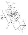
- FIG. 3is an exploded isometric view of a dynamic braking grid package including a flow directing diffuser.
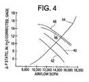
- FIG. 4is a comparison of the pressure drop performance of a dynamic braking grid package having a prior art flow blocking diffuser and a similar system having a flow directing diffuser.
- FIG. 3is an exploded perspective view of a dynamic braking grid package 25 including a resistor grid stack 22 disposed downstream of a fan/motor 25 .
- the flow directing diffuser 24is disposed between the fan/motor 25 and the resistor grid stack 22 within the stream of cooling air 21 produced by the fan/motor 25 .
- the fan/motor 25 and the flow directing diffuser 24function together as a cooling apparatus 27 for the resistor grid stack 22 .
- the flow directing diffuser 24includes a plurality of turning vane members 26 that each function to direct a portion of the airflow traveling through the diffuser 24 away from a high velocity area and into a low velocity area. Proper selection and location of such turning vane members 26 can result in an improved flow velocity distribution together with no decrease or a small increase in the total volume of airflow provided through a dynamic braking grid when compared to the volume of airflow that would otherwise be provided by the fan/motor alone with no diffuser in place.
- the flow directing diffuser 24does not block and reduce the air flow as would a prior art diffuser plate 12 .
- flow directing diffuser 24contains two different geometries of turning vane members 26 .
- a first turning vane member 28is a ring-shaped annular member disposed about the axis A of the direction of flow.
- First turning vane member 28is illustrated as having a generally octagonal shape and being formed from a plurality of interconnected flat plates 30 .
- a smoothly curved generally circular geometrymay be used in lieu of the octagonal shape.
- the individual plates 30 or a generally circular membermay be curved into an airfoil shape.
- the platesmay be metal, such as aluminum, or fiber composite or other material known in the art.
- Each plate 30is oriented at an angle with respect to the axis A so that the annular first turning vane member 28 has an inside diameter dimension measured in a direction perpendicular to the axis A that decreases along axis A in the direction of the airflow.
- the effect of these angled plates 30is to redirect a portion of the air from the relatively higher velocity annular portion of the airflow into the relatively lower velocity central area.
- a portion of the high velocity airflowhas some of its axial momentum converted into a radial velocity component, thereby moving a greater portion of the volume of the air into the central area of the air stream.
- the axial flow velocity profile of the air streamis at least partially normalized downstream of the flow directing diffuser 24 , with the resulting velocity profile being similar to that illustrated in FIG. 1 as achievable downstream of a prior art flow blocking diffuser plate 12 .
- a second turning vanesuch as corner member 32 is associated with each of the four corners 34 of generally rectangular-shaped duct 36 surrounding and defining the shape of the air stream.
- Such second turning vane members 32are illustrated as being two interconnected flat plates 38 forming a V-shape, although any variety of other shapes may be used, such as described above with respect to first turning vane member 28 .
- Each plateis disposed at an angle relative to the axis A to become closer to duct 36 as the air progresses downstream in the direction of axis A. This angle will impart a radially outward flow velocity component to a portion of the airflow.
- the effect of these angled plates 38is to redirect a portion of the air flowing along the relatively higher velocity annular portion of the airflow into the relatively lower velocity corner portion of the airflow proximate corners 34 of duct 36 .
- Prior art locomotive dynamic braking systemsutilize axial fans to direct a flow of cooling air in an axial direction toward the resistor grids.
- an axial fanencounters a static pressure sufficiently high to exceed the lift coefficient of the blade airfoil, aerodynamic breakdown of the air flow over the airfoil will occur and the total air flow generated by the fan will be dramatically reduced.
- stall conditionsare a design limitation for prior art brake resistor grid cooling systems.
- Variables affecting the fan performanceinclude altitude, temperature, barometric pressure, and wind speed and direction. Because the prior art cooling systems are prone to a rapid decrease in the cooling air flow rate in the event of stall conditions, such systems must be very conservatively designed to minimize such occurrences.
- a mixed flow fan 54may be used advantageously in the cooling apparatus 27 of the present invention to provide additional stall margin.
- Fan 54may be driven by motor 23 by a drive shaft, belt, chain or other known power transmission device.
- a mixed flow fancombines the features of an axial fan and a centrifugal fan and generates an axial air flow having a radial velocity component.
- Such a designis advantageous in the cooling apparatus 27 of the present invention, since the radial velocity component will be naturally redirected by the downstream duct 36 to increase the flow velocity proximate the corners 34 of the duct.
- a mixed flow fan 54may provide a higher cooling flow than an axial flow fan with the same power consumption, or it may provide a lower power consumption with a lower noise level to produce the same total flow volume as an axial flow fan.
- the near-stall performance characteristics of a mixed flow fanare well suited for this cooling application, since the total flow rate produced by a mixed flow fan will drop more gradually than an axial fan as the back pressure against the fan increases to the point of aerodynamic failure.
- the mixed flow fan 54 of the present inventionmay provide a reduced but non-zero flow rate, and it will not drop precipitously to zero air flow as can possibly occur with the axial fan 10 of the prior art.
- the mixed flow fan 54is thus advantageously combined with a downstream duct 36 to provide cooling air to a dynamic braking resistor grid package 22 for a locomotive.
- One or more turning vane members 28 , 32may be provided within the duct 36 to further equalize the flow velocity distribution at the inlet of the grid package 22 .
- the flow directing members 26function to move a portion of the higher velocity air produced by a fan 54 into the areas of lower velocity air. This allows for improved pressure drop characteristics when compared to prior art flow blocking diffuser systems. Due to better pressure recovery, a fan operating with the flow directing diffuser 24 of the present invention may have a performance curve which is comparable to, or slightly better than, the fan operation with no diffuser. In contrast, the prior art flow blocking diffuser 12 produces a distinct pressure loss, as illustrated in FIG. 4 .
- Curve 40illustrates the use of a prior art axial flow fan operating at 3,600 RPM with no diffuser.
- Curve 42illustrates the use of this same axial flow fan at the same speed with a prior art flow blocking diffuser plate 12 .
- Curve 46illustrates the use of a mixed flow fan operating at 3,600 RPM within the same size and noise envelopes as the prior art axial flow fan and with no diffuser.
- the mixed flow fanprovides an increase in the system flow rate of over 1,000 SCFM when compared to the axial flow fan without a diffuser.
- Curve 48illustrates the use of this same mixed flow fan at the same operating speed with a flow directing diffuser 24 . Notice that in this embodiment, the overall system flow is slightly increased by the use of the flow directing diffuser 24 .
- the flow directing diffuser 24may be formed of one or more turning vane members disposed at one or more positions along the axis A of the flow stream.
- First and second turning vane members 28 , 32are illustrated as being positioned at the same position along axis A with interconnecting support member 50 connected there between.
- a third turning vane member 52may be positioned at a second position along axis A to cooperate with the first and second turning vane members 28 , 32 in redirecting the flow of cooling air.
- the third turning vane member 52is disposed in a position relative to the direction of flow of the air stream such that a portion of the higher velocity air is directed into an area of lower velocity air.
- Third turning vane member 52is illustrated as having an annular ring shape disposed at an angle to axis A for directing a portion of the donut-shaped high velocity air stream into a center area within the duct 36 where the flow velocity exiting the fan blades 10 is relatively low.
- third turning vane member 52 and first turning vane member 28cooperate to increase the velocity of the air stream near the center of the duct 36 .
- the flow transition length of the present designis greater than that of a prior art single flow distribution plate design.
- the velocity profile across the end of the resistor grid stack 22has about a 6% variation, thus providing a temperature variation of approximately 10% across the grid stack. This compares favorably with a prior art diffuser plate designs.
Landscapes
- Engineering & Computer Science (AREA)
- Mechanical Engineering (AREA)
- General Engineering & Computer Science (AREA)
- Physics & Mathematics (AREA)
- Thermal Sciences (AREA)
- Motor Or Generator Cooling System (AREA)
Abstract
Description
This application claims benefit of the Oct. 22, 2001, filing date of U.S. provisional patent application serial No. 60/338,900.
This invention relates generally to traction motor dynamic braking systems in locomotives and more particularly to an air-cooled resistor grid package for a dynamic braking system.
In a conventional rail locomotive, a diesel engine is used to drive an alternator. The alternator, in turn, supplies electrical current to drive a plurality of electrical traction motors. The traction motors provide the motive force for propelling the locomotive in the forward and reverse directions. In addition to providing a driving force, the traction motors may also perform a braking function. In the braking mode, the traction motors are configured to generate electricity instead of consuming it. As generators, the traction motors convert the kinetic energy of motion of the locomotive into electrical energy, thereby providing a dynamic braking action to slow the movement of the locomotive. The electrical energy generated during dynamic braking can not be used or stored conveniently on-board the locomotive, so it is converted to heat energy by connecting the traction motors to a bank of electrical resistors. Such electrical resistors are commonly called dynamic braking grids. The dynamic braking grids are cooled by fan-driven air, thereby transferring the energy generated by the dynamic braking to the ambient environment.
A typical stack of braking grids may occupying a volume of only about 50 cubic feet and may be used to dissipate approximately 1.8 MW of power. A limiting factor in the amount of dynamic braking force that may be applied to a locomotive is the upper temperature limit of the materials of the dynamic braking grids. The efficient transfer of heat energy from the resistors to the ambient environment is critical to the proper performance of a dynamic braking system. Because the design of the braking grid package is subject to size and noise limitations, it is not always possible to simply increase the number of braking resistors and the size and capacity of the cooling fans.
Working within predetermined design boundaries, it is desirable to minimize hot spots in the braking grids in order to maximize the energy dissipation across the entire grid while avoiding localized material failure. A typical fan will provide a very uneven airflow velocity distribution at the fan outlet, as illustrated in FIG.1. Typically, the outlet velocity is highest proximate the center of theimpeller fan blades 10 and lowest at the root and tips of the blades. Therefore, it is known in the art to provide a flow diffuser plate between the fan outlet and the resistor stack inlet. The flow diffuser plate is aflat plate 12 typically formed of metal and having a pattern ofholes 14 formed there through, as illustrated in FIG.2. In theannular ring area 16 of theplate 12 aligned with the high velocity portions of the fan airflow, the quantity and/or size ofholes 14 per unit area of the plate is relatively low. In thecentral area 18 andcorner areas 20 of theplate 12 aligned with the low velocity portions of the fan airflow, the quantity and/or size ofholes 14 per unit area of the plate is relatively high. This uneven distribution of openings in thediffuser plate 12 has the effect of making the distribution of airflow volume and velocity downstream of thediffuser plate 12 much more even than that provided at the fan outlet, as illustrated in FIG.1. Thediffuser plate 12 also serves to reshape the air stream from the generally circular cross-section of thefan blades 10 to the generally rectangular cross-section of the downstreamresistor grid stack 22. Thus, the cooling provided across theresistor grid stack 22 is more evenly distributed as a result of the action of thediffuser plate 12 and hot spots therein are minimized or eliminated.
Unfortunately, the priorart diffuser plate 12 is essentially a flow blocking device and it creates a significant pressure drop in the air stream, thereby reducing the total volume of cooling airflow provided through theresistor grid stack 22. To compensate for this airflow reduction, a larger and/or more powerful fan motor2 may be provided, with the associated cost, weight and noise penalties.
Thus, there is a need for an improved locomotive dynamic braking grid package. In particular, there is a need for an air delivery system for a resistor grid stack that provides a high volume flow of air having a relatively constant cross-sectional velocity profile.
An apparatus for at least partially normalizing an axial flow velocity distribution of a flow of cooling air supplied by a fan to a locomotive dynamic braking grid resistor stack is described herein as including: a flow turning vane disposed in the flow of cooling air downstream of the fan and upstream of the resistor stack, the flow turning vane oriented within the flow of cooling air to direct a portion of the cooling air from a relatively higher velocity portion of the flow of cooling air into a relatively lower velocity portion of the flow of cooling air. The flow turning vane may include an annular member having an inside diameter dimension that decreases along an axis in the direction of the airflow for directing a portion of the cooling air from a relatively higher velocity annular portion of the flow of cooling air into a relatively lower velocity center portion of the flow of cooling air. The flow turning vane may further include a corner member disposed proximate a corner of a duct bounding the flow of cooling air for directing a portion of air from a relatively higher velocity annular portion of the flow of cooling air into a relatively lower velocity corner portion of the flow of cooling air. The apparatus may include a first flow turning vane and a second flow turning vane disposed in the flow of cooling air downstream of the first flow turning vane and upstream of the resistor stack.
A cooling apparatus for a locomotive dynamic brake resistor grid stack is described herein as including: a fan for inducing a flow of air having a cross-section with a relatively higher velocity area and a relatively lower velocity area; a duct for directing the flow of air away from the fan to an inlet to a dynamic brake resistor grid stack; and a flow directing diffuser disposed within the duct for directing a portion of the flow of air from the relatively higher velocity area into the relatively lower velocity area to at least partially normalize a flow velocity distribution of the air entering the inlet to the grid stack. The fan may be a mixed flow fan.
A locomotive dynamic braking grid package is described as including: a plurality of electrical resistors packaged in a grid stack; a fan for producing a flow of cooling air; a duct for directing the flow of cooling air from the fan to the grid stack for cooling the plurality of electrical resistors; and a flow turning vane disposed within the duct for directing a portion of the cooling air from a higher axial velocity area into a lower axial velocity area of the duct to at least partially normalize an axial flow velocity profile of the cooling air as it enters the grid stack. The fan may be a mixed flow fan.
In a further embodiment, a locomotive dynamic braking grid package is described as including: a plurality of electrical resistors packaged in a grid stack; a mixed flow fan for producing a flow of cooling air; and a duct for directing the flow of cooling air from the fan to the grid stack for cooling the plurality of electrical resistors. The locomotive dynamic braking grid package may further include an annular flow turning vane disposed within the duct for directing a portion of the cooling air from a higher axial velocity annular area into a lower axial velocity center area of the duct to at least partially normalize an axial flow velocity profile of the cooling air as it enters the grid stack.
The features and advantages of the present invention will become apparent from the following detailed description of the invention when read with the accompanying drawings in which:
FIG. 1 is a schematic illustration of a prior art dynamic braking grid package showing the cooling air velocity profile upstream and downstream of a prior art diffuser plate disposed between the fan and the resistor grid stack.
FIG. 2 is a plan view of a prior art diffuser plate showing the uneven distribution of holes formed there through.
FIG. 3 is an exploded isometric view of a dynamic braking grid package including a flow directing diffuser.
FIG. 4 is a comparison of the pressure drop performance of a dynamic braking grid package having a prior art flow blocking diffuser and a similar system having a flow directing diffuser.
The inventors have discovered that a flow directing diffuser may be used to provide the required airflow velocity distribution correction in a dynamicbraking grid package 11 without creating any adverse reduction in the total volume of airflow that is generated by the fan/motor combination. One suchflow directing diffuser 24 is illustrated in FIG.3. FIG. 3 is an exploded perspective view of a dynamicbraking grid package 25 including aresistor grid stack 22 disposed downstream of a fan/motor 25. Theflow directing diffuser 24 is disposed between the fan/motor 25 and theresistor grid stack 22 within the stream ofcooling air 21 produced by the fan/motor 25. The fan/motor 25 and theflow directing diffuser 24 function together as acooling apparatus 27 for theresistor grid stack 22.
Theflow directing diffuser 24 includes a plurality of turningvane members 26 that each function to direct a portion of the airflow traveling through thediffuser 24 away from a high velocity area and into a low velocity area. Proper selection and location of suchturning vane members 26 can result in an improved flow velocity distribution together with no decrease or a small increase in the total volume of airflow provided through a dynamic braking grid when compared to the volume of airflow that would otherwise be provided by the fan/motor alone with no diffuser in place. Theflow directing diffuser 24 does not block and reduce the air flow as would a priorart diffuser plate 12.
In one embodiment,flow directing diffuser 24 contains two different geometries of turningvane members 26. A firstturning vane member 28 is a ring-shaped annular member disposed about the axis A of the direction of flow. First turningvane member 28 is illustrated as having a generally octagonal shape and being formed from a plurality of interconnectedflat plates 30. One may appreciate that a smoothly curved generally circular geometry may be used in lieu of the octagonal shape. Furthermore, theindividual plates 30 or a generally circular member may be curved into an airfoil shape. The plates may be metal, such as aluminum, or fiber composite or other material known in the art. Eachplate 30 is oriented at an angle with respect to the axis A so that the annular firstturning vane member 28 has an inside diameter dimension measured in a direction perpendicular to the axis A that decreases along axis A in the direction of the airflow. The effect of theseangled plates 30 is to redirect a portion of the air from the relatively higher velocity annular portion of the airflow into the relatively lower velocity central area. A portion of the high velocity airflow has some of its axial momentum converted into a radial velocity component, thereby moving a greater portion of the volume of the air into the central area of the air stream. Thus, the axial flow velocity profile of the air stream is at least partially normalized downstream of theflow directing diffuser 24, with the resulting velocity profile being similar to that illustrated in FIG. 1 as achievable downstream of a prior art flow blockingdiffuser plate 12.
A second turning vane such ascorner member 32 is associated with each of the fourcorners 34 of generally rectangular-shapedduct 36 surrounding and defining the shape of the air stream. Such secondturning vane members 32 are illustrated as being two interconnectedflat plates 38 forming a V-shape, although any variety of other shapes may be used, such as described above with respect to firstturning vane member 28. Each plate is disposed at an angle relative to the axis A to become closer toduct 36 as the air progresses downstream in the direction of axis A. This angle will impart a radially outward flow velocity component to a portion of the airflow. The effect of theseangled plates 38 is to redirect a portion of the air flowing along the relatively higher velocity annular portion of the airflow into the relatively lower velocity corner portion of the airflowproximate corners 34 ofduct 36.
Prior art locomotive dynamic braking systems utilize axial fans to direct a flow of cooling air in an axial direction toward the resistor grids. When an axial fan encounters a static pressure sufficiently high to exceed the lift coefficient of the blade airfoil, aerodynamic breakdown of the air flow over the airfoil will occur and the total air flow generated by the fan will be dramatically reduced. Such stall conditions are a design limitation for prior art brake resistor grid cooling systems. Variables affecting the fan performance include altitude, temperature, barometric pressure, and wind speed and direction. Because the prior art cooling systems are prone to a rapid decrease in the cooling air flow rate in the event of stall conditions, such systems must be very conservatively designed to minimize such occurrences. The present inventors have found that amixed flow fan 54 may be used advantageously in thecooling apparatus 27 of the present invention to provide additional stall margin.Fan 54 may be driven bymotor 23 by a drive shaft, belt, chain or other known power transmission device. A mixed flow fan combines the features of an axial fan and a centrifugal fan and generates an axial air flow having a radial velocity component. Such a design is advantageous in thecooling apparatus 27 of the present invention, since the radial velocity component will be naturally redirected by thedownstream duct 36 to increase the flow velocity proximate thecorners 34 of the duct. Amixed flow fan 54 may provide a higher cooling flow than an axial flow fan with the same power consumption, or it may provide a lower power consumption with a lower noise level to produce the same total flow volume as an axial flow fan. Importantly, the near-stall performance characteristics of a mixed flow fan are well suited for this cooling application, since the total flow rate produced by a mixed flow fan will drop more gradually than an axial fan as the back pressure against the fan increases to the point of aerodynamic failure. Thus, during abnormal transient conditions, such as encountering a cross wind when operating at a high altitude, themixed flow fan 54 of the present invention may provide a reduced but non-zero flow rate, and it will not drop precipitously to zero air flow as can possibly occur with theaxial fan 10 of the prior art. Themixed flow fan 54 is thus advantageously combined with adownstream duct 36 to provide cooling air to a dynamic brakingresistor grid package 22 for a locomotive. One or moreturning vane members duct 36 to further equalize the flow velocity distribution at the inlet of thegrid package 22.
Theflow directing members 26 function to move a portion of the higher velocity air produced by afan 54 into the areas of lower velocity air. This allows for improved pressure drop characteristics when compared to prior art flow blocking diffuser systems. Due to better pressure recovery, a fan operating with theflow directing diffuser 24 of the present invention may have a performance curve which is comparable to, or slightly better than, the fan operation with no diffuser. In contrast, the prior artflow blocking diffuser 12 produces a distinct pressure loss, as illustrated in FIG.4.Curve 40 illustrates the use of a prior art axial flow fan operating at 3,600 RPM with no diffuser.Curve 42 illustrates the use of this same axial flow fan at the same speed with a prior art flow blockingdiffuser plate 12. Notice that the use of thediffuser 12 results in a reduction in the total system airflow of approximately 1,000 SCFM as predicted bysystem curve 44.Curve 46 illustrates the use of a mixed flow fan operating at 3,600 RPM within the same size and noise envelopes as the prior art axial flow fan and with no diffuser. The mixed flow fan provides an increase in the system flow rate of over 1,000 SCFM when compared to the axial flow fan without a diffuser.Curve 48 illustrates the use of this same mixed flow fan at the same operating speed with aflow directing diffuser 24. Notice that in this embodiment, the overall system flow is slightly increased by the use of theflow directing diffuser 24.
Theflow directing diffuser 24 may be formed of one or more turning vane members disposed at one or more positions along the axis A of the flow stream. First and secondturning vane members support member 50 connected there between. A thirdturning vane member 52 may be positioned at a second position along axis A to cooperate with the first and secondturning vane members turning vane member 52 is disposed in a position relative to the direction of flow of the air stream such that a portion of the higher velocity air is directed into an area of lower velocity air. Thirdturning vane member 52 is illustrated as having an annular ring shape disposed at an angle to axis A for directing a portion of the donut-shaped high velocity air stream into a center area within theduct 36 where the flow velocity exiting thefan blades 10 is relatively low. Thus, thirdturning vane member 52 and first turningvane member 28 cooperate to increase the velocity of the air stream near the center of theduct 36. Thus, the flow transition length of the present design is greater than that of a prior art single flow distribution plate design. By achieving the desired flow redistribution in two steps rather than with a single turning vane member or with a single flow distribution plate, the turbulence created in the air stream is reduced compared to a single step design, thus further improving the efficiency of the system. In one embodiment, the velocity profile across the end of theresistor grid stack 22 has about a 6% variation, thus providing a temperature variation of approximately 10% across the grid stack. This compares favorably with a prior art diffuser plate designs.
While the preferred embodiments of the present invention have been shown and described herein, it will be obvious that such embodiments are provided by way of example only. Numerous variations, changes and substitutions will occur to those of skill in the art without departing from the invention herein. Accordingly, it is intended that the invention be limited only by the spirit and scope of the appended claims.
Claims (13)
1. An apparatus for at least partially normalizing an axial flow velocity distribution of a flow of cooling air supplied by a fan to a locomotive dynamic braking grid resistor stack, the apparatus comprising:
a duct bounding the flow of cooling air; and
a flow turning vane comprising a corner member disposed proximate a corner of the duct and disposed remote from a center portion of the flow of cooling air and spaced apart from the duct to allow a portion of the flow of cooling air to pass between the corner member and the corner, the corner member extending into a relatively higher velocity annular portion of the flow of cooling air and having a downstream portion disposed closer to the corner than an upstream portion for directing a portion of the cooling air from the relatively higher velocity annular portion of the flow of cooling air into a relatively lower velocity corner portion of the flow of cooling air without restricting the center portion of the flow of cooling air.
2. The apparatus ofclaim 1 , wherein the flow turning vane further comprises a V-shaped corner member having a first portion disposed in the relatively higher velocity annular portion and having a second portion extending toward the corner.
3. The apparatus ofclaim 1 , further comprising:
an annular member disposed within the duct for directing a portion of the cooling air from the relatively higher velocity annular portion of the flow of cooling air into the center portion of the flow of cooling air; and wherein
the corner member is connected to the duct and the annular member is connected to the corner member in order to provide support for both the corner member and the annular member without restricting the center portion of the flow of cooling air.
4. The apparatus ofclaim 3 , wherein the annular member comprises a first annular member, and further comprising:
a second annular member disposed in the flow of cooling air downstream of the first annular member and upstream of the resistor stack, the second annular member cooperating with the first annular member for directing the portion of the cooling air from the relatively higher velocity annular portion of the flow of cooling air into the center portion of the flow of cooling air with reduced turbulence in the flow of cooling air than would be created by directing the same portion of the cooling air into the center portion of the flow of cooling air with only a single annular member.
5. The apparatus ofclaim 1 , wherein the flow turning vane further comprises two interconnected flat plates forming a V-shape, each plate connected to the duct at one end and connected to the other plate at an opposed end and having a downstream portion disposed closer to the corner than an upstream portion for directing the portion of the cooling air from the relatively higher velocity annular portion of the flow of cooling air into the relatively lower velocity corner portion of the flow of cooling air without imparting tangential velocity to the flow of cooling air.
6. A cooling apparatus for a locomotive dynamic brake resistor grid stack, the cooling apparatus comprising:
a fan for inducing a flow of air having a cross-section with a relatively higher velocity annular area and a relatively lower velocity center area;
a duct for directing the flow of air away from the fan to an inlet of a locomotive dynamic brake resistor grid stack; and
a flow directing vane disposed within the duct for directing a portion of the flow of air from the relatively higher velocity annular area into a corner region of the duct without restricting the relatively lower velocity center area to at least partially normalize a flow velocity distribution of the air entering the inlet of the grid stack;
wherein the flow directing vane is spaced apart from a corner of the duct and extends into the annular area with a downstream portion being disposed closer to the corner than an upstream portion for directing the portion of air from the annular area into the corner region.
7. The cooling apparatus ofclaim 6 , wherein the fan comprises a mixed flow fan.
8. The cooling apparatus ofclaim 6 , further comprising an annular member connected to the flow directing vane for directing a portion of the flow of air from the relatively higher velocity annular area to the relatively lower velocity center area.
9. The cooling apparatus ofclaim 8 , wherein the annular member comprises a first annular member, and further comprising a second annular member disposed within the duct and cooperating with the first annular member to direct the portion of the flow of air from the relatively higher velocity annular area to the center area with reduced turbulence in the flow of air than would be created by directing the same portion of the air into the center area with only a single annular member.
10. The cooling apparatus ofclaim 6 , wherein the flow directing vane further comprises two interconnected flat plates forming a V-shape, each plate connected to the duct at one end and connected to the other plate at an opposed end and having a downstream portion disposed closer to the corner than an upstream portion for directing the portion of the flow of air from the relatively higher velocity annular area into the corner region without imparting tangential velocity to the flow of air.
11. A locomotive dynamic braking grid package comprising:
a plurality of electrical resistors packaged in a grid stack;
a fan producing a flow of cooling air having a relatively higher velocity annular portion and a relatively lower velocity center portion;
a duct for directing the flow of cooling air from the fan to the grid stack for cooling the plurality of electrical resistors; and
a flow turning vane disposed within the duct remote from the center portion for directing a portion of the cooling air from the higher velocity annular portion into a corner area of the duct without restricting the relatively lower velocity center portion to at least partially normalize an axial flow velocity profile of the cooling air as it enters the grid stack;
wherein the flow turning vane is spaced apart from a corner of the duct and extends into the annular portion of the flow of cooling air with a downstream portion being disposed closer to the corner than an upstream portion for directing the portion of the cooling air from the higher velocity annular portion into the corner area.
12. The locomotive dynamic braking grid package ofclaim 11 , wherein the fan comprises a mixed flow fan.
13. The locomotive dynamic braking grid package ofclaim 11 , wherein the flow turning vane further comprises two interconnected flat plates forming a V-shape, each plate connected to the duct at one end and connected to the other plate at an opposed end and having a downstream portion disposed closer to the corner than an upstream portion for directing the portion of the cooling air from the higher velocity annular portion into the corner area without imparting tangential velocity to the flow of cooling air.
Priority Applications (1)
| Application Number | Priority Date | Filing Date | Title |
|---|---|---|---|
| US10/074,733US6749043B2 (en) | 2001-10-22 | 2002-02-13 | Locomotive brake resistor cooling apparatus |
Applications Claiming Priority (2)
| Application Number | Priority Date | Filing Date | Title |
|---|---|---|---|
| US33890001P | 2001-10-22 | 2001-10-22 | |
| US10/074,733US6749043B2 (en) | 2001-10-22 | 2002-02-13 | Locomotive brake resistor cooling apparatus |
Publications (2)
| Publication Number | Publication Date |
|---|---|
| US20030075396A1 US20030075396A1 (en) | 2003-04-24 |
| US6749043B2true US6749043B2 (en) | 2004-06-15 |
Family
ID=26756002
Family Applications (1)
| Application Number | Title | Priority Date | Filing Date |
|---|---|---|---|
| US10/074,733Expired - Fee RelatedUS6749043B2 (en) | 2001-10-22 | 2002-02-13 | Locomotive brake resistor cooling apparatus |
Country Status (1)
| Country | Link |
|---|---|
| US (1) | US6749043B2 (en) |
Cited By (63)
| Publication number | Priority date | Publication date | Assignee | Title |
|---|---|---|---|---|
| US20030173830A1 (en)* | 2002-03-18 | 2003-09-18 | Adc Dsl Systems, Inc. | Temperature and barometric responsive fan system |
| US20050024002A1 (en)* | 2003-07-31 | 2005-02-03 | Jackson Robert D. | Inductive heating system and method for controlling discharge of electric energy from machines |
| US20050028546A1 (en)* | 2003-07-11 | 2005-02-10 | Henry Young | Silencing equipment for an air-cooling assembly |
| US20050276020A1 (en)* | 2004-05-27 | 2005-12-15 | Ahmad Raed H | System and method for a cooling system |
| US20060022631A1 (en)* | 2004-07-23 | 2006-02-02 | Marsh Gregory A | Locomotive dynamic braking grid package configuration |
| US20100183993A1 (en)* | 2008-01-07 | 2010-07-22 | Mcalister Roy E | Integrated fuel injectors and igniters and associated methods of use and manufacture |
| US20110041784A1 (en)* | 2009-02-17 | 2011-02-24 | Mcalister Technologies, Llc | Energy system for dwelling support |
| US20110061295A1 (en)* | 2009-02-17 | 2011-03-17 | Mcalister Technologies, Llc | Sustainable economic development through integrated production of renewable energy, materials resources, and nutrient regimes |
| US20110146619A1 (en)* | 2008-01-07 | 2011-06-23 | Mcalister Technologies, Llc | Adaptive control system for fuel injectors and igniters |
| US20110184876A1 (en)* | 2010-12-30 | 2011-07-28 | Ziprealty, Inc. | Virtual bidding platform for lead allocation in real estate applications |
| US20110198211A1 (en)* | 2010-02-13 | 2011-08-18 | Mcalister Technologies, Llc | Reactors for conducting thermochemical processes with solar heat input, and associated systems and methods |
| US20110200897A1 (en)* | 2009-02-17 | 2011-08-18 | Mcalister Technologies, Llc | Delivery systems with in-line selective extraction devices and associated methods of operation |
| US20110207008A1 (en)* | 2009-02-17 | 2011-08-25 | Mcalister Technologies, Llc | Induction for thermochemical processes, and associated systems and methods |
| US20110230573A1 (en)* | 2010-02-13 | 2011-09-22 | Mcalister Technologies, Llc | Reactor vessels with pressure and heat transfer features for producing hydrogen-based fuels and structural elements, and associated systems and methods |
| US20110226988A1 (en)* | 2008-01-07 | 2011-09-22 | Mcalister Technologies, Llc | Chemical processes and reactors for efficiently producing hydrogen fuels and structural materials, and associated systems and methods |
| US8187549B2 (en) | 2010-02-13 | 2012-05-29 | Mcalister Technologies, Llc | Chemical reactors with annularly positioned delivery and removal devices, and associated systems and methods |
| US8297265B2 (en) | 2010-02-13 | 2012-10-30 | Mcalister Technologies, Llc | Methods and systems for adaptively cooling combustion chambers in engines |
| US8365700B2 (en) | 2008-01-07 | 2013-02-05 | Mcalister Technologies, Llc | Shaping a fuel charge in a combustion chamber with multiple drivers and/or ionization control |
| US8387599B2 (en) | 2008-01-07 | 2013-03-05 | Mcalister Technologies, Llc | Methods and systems for reducing the formation of oxides of nitrogen during combustion in engines |
| US8413634B2 (en) | 2008-01-07 | 2013-04-09 | Mcalister Technologies, Llc | Integrated fuel injector igniters with conductive cable assemblies |
| US8528519B2 (en) | 2010-10-27 | 2013-09-10 | Mcalister Technologies, Llc | Integrated fuel injector igniters suitable for large engine applications and associated methods of use and manufacture |
| US8561598B2 (en) | 2008-01-07 | 2013-10-22 | Mcalister Technologies, Llc | Method and system of thermochemical regeneration to provide oxygenated fuel, for example, with fuel-cooled fuel injectors |
| US8561591B2 (en) | 2010-12-06 | 2013-10-22 | Mcalister Technologies, Llc | Integrated fuel injector igniters having force generating assemblies for injecting and igniting fuel and associated methods of use and manufacture |
| US8669014B2 (en) | 2011-08-12 | 2014-03-11 | Mcalister Technologies, Llc | Fuel-cell systems operable in multiple modes for variable processing of feedstock materials and associated devices, systems, and methods |
| US8673509B2 (en) | 2011-08-12 | 2014-03-18 | Mcalister Technologies, Llc | Fuel-cell systems operable in multiple modes for variable processing of feedstock materials and associated devices, systems, and methods |
| US8671870B2 (en) | 2011-08-12 | 2014-03-18 | Mcalister Technologies, Llc | Systems and methods for extracting and processing gases from submerged sources |
| US8683988B2 (en) | 2011-08-12 | 2014-04-01 | Mcalister Technologies, Llc | Systems and methods for improved engine cooling and energy generation |
| US8684117B2 (en) | 2011-06-17 | 2014-04-01 | General Electric Company | Methods and systems for cooling in a vehicle |
| US8727242B2 (en) | 2010-02-13 | 2014-05-20 | Mcalister Technologies, Llc | Fuel injector assemblies having acoustical force modifiers and associated methods of use and manufacture |
| US8734546B2 (en) | 2011-08-12 | 2014-05-27 | Mcalister Technologies, Llc | Geothermal energization of a non-combustion chemical reactor and associated systems and methods |
| US8800527B2 (en) | 2012-11-19 | 2014-08-12 | Mcalister Technologies, Llc | Method and apparatus for providing adaptive swirl injection and ignition |
| US8808529B2 (en) | 2009-02-17 | 2014-08-19 | Mcalister Technologies, Llc | Systems and methods for sustainable economic development through integrated full spectrum production of renewable material resources using solar thermal |
| US8814983B2 (en) | 2009-02-17 | 2014-08-26 | Mcalister Technologies, Llc | Delivery systems with in-line selective extraction devices and associated methods of operation |
| US8820275B2 (en) | 2011-02-14 | 2014-09-02 | Mcalister Technologies, Llc | Torque multiplier engines |
| US8821602B2 (en) | 2011-08-12 | 2014-09-02 | Mcalister Technologies, Llc | Systems and methods for providing supplemental aqueous thermal energy |
| US8820293B1 (en) | 2013-03-15 | 2014-09-02 | Mcalister Technologies, Llc | Injector-igniter with thermochemical regeneration |
| US8826657B2 (en) | 2011-08-12 | 2014-09-09 | Mcallister Technologies, Llc | Systems and methods for providing supplemental aqueous thermal energy |
| US8851046B2 (en) | 2009-08-27 | 2014-10-07 | Mcalister Technologies, Llc | Shaping a fuel charge in a combustion chamber with multiple drivers and/or ionization control |
| US8851047B2 (en) | 2012-08-13 | 2014-10-07 | Mcallister Technologies, Llc | Injector-igniters with variable gap electrode |
| US8876483B2 (en) | 2010-01-14 | 2014-11-04 | Neptco, Inc. | Wind turbine rotor blade components and methods of making same |
| US8888408B2 (en) | 2011-08-12 | 2014-11-18 | Mcalister Technologies, Llc | Systems and methods for collecting and processing permafrost gases, and for cooling permafrost |
| US8911703B2 (en) | 2011-08-12 | 2014-12-16 | Mcalister Technologies, Llc | Reducing and/or harvesting drag energy from transport vehicles, including for chemical reactors, and associated systems and methods |
| US8919377B2 (en) | 2011-08-12 | 2014-12-30 | Mcalister Technologies, Llc | Acoustically actuated flow valve assembly including a plurality of reed valves |
| US8926719B2 (en) | 2013-03-14 | 2015-01-06 | Mcalister Technologies, Llc | Method and apparatus for generating hydrogen from metal |
| US8997718B2 (en) | 2008-01-07 | 2015-04-07 | Mcalister Technologies, Llc | Fuel injector actuator assemblies and associated methods of use and manufacture |
| US9039327B2 (en) | 2011-08-12 | 2015-05-26 | Mcalister Technologies, Llc | Systems and methods for collecting and processing permafrost gases, and for cooling permafrost |
| US9091238B2 (en) | 2012-11-12 | 2015-07-28 | Advanced Green Technologies, Llc | Systems and methods for providing motion amplification and compensation by fluid displacement |
| US9115325B2 (en) | 2012-11-12 | 2015-08-25 | Mcalister Technologies, Llc | Systems and methods for utilizing alcohol fuels |
| US9188086B2 (en) | 2008-01-07 | 2015-11-17 | Mcalister Technologies, Llc | Coupled thermochemical reactors and engines, and associated systems and methods |
| US9200561B2 (en) | 2012-11-12 | 2015-12-01 | Mcalister Technologies, Llc | Chemical fuel conditioning and activation |
| US9206045B2 (en) | 2010-02-13 | 2015-12-08 | Mcalister Technologies, Llc | Reactor vessels with transmissive surfaces for producing hydrogen-based fuels and structural elements, and associated systems and methods |
| US9231267B2 (en) | 2009-02-17 | 2016-01-05 | Mcalister Technologies, Llc | Systems and methods for sustainable economic development through integrated full spectrum production of renewable energy |
| US9279398B2 (en) | 2013-03-15 | 2016-03-08 | Mcalister Technologies, Llc | Injector-igniter with fuel characterization |
| US9302681B2 (en) | 2011-08-12 | 2016-04-05 | Mcalister Technologies, Llc | Mobile transport platforms for producing hydrogen and structural materials, and associated systems and methods |
| US9309846B2 (en) | 2012-11-12 | 2016-04-12 | Mcalister Technologies, Llc | Motion modifiers for fuel injection systems |
| WO2016099977A1 (en)* | 2014-12-15 | 2016-06-23 | Dayton-Phoenix Group, Inc. | Cooling fan vane assembly for a resistor grid |
| US9410474B2 (en) | 2010-12-06 | 2016-08-09 | Mcalister Technologies, Llc | Integrated fuel injector igniters configured to inject multiple fuels and/or coolants and associated methods of use and manufacture |
| US9511663B2 (en) | 2013-05-29 | 2016-12-06 | Mcalister Technologies, Llc | Methods for fuel tank recycling and net hydrogen fuel and carbon goods production along with associated apparatus and systems |
| US9522379B2 (en) | 2011-08-12 | 2016-12-20 | Mcalister Technologies, Llc | Reducing and/or harvesting drag energy from transport vehicles, including for chemical reactors, and associated systems and methods |
| US9534296B2 (en) | 2013-03-15 | 2017-01-03 | Mcalister Technologies, Llc | Methods of manufacture of engineered materials and devices |
| US9815374B2 (en) | 2014-09-25 | 2017-11-14 | Dayton-Phoenix Group, Inc. | Braking grid cooling system |
| US10137542B2 (en) | 2010-01-14 | 2018-11-27 | Senvion Gmbh | Wind turbine rotor blade components and machine for making same |
| US20250154957A1 (en)* | 2023-11-13 | 2025-05-15 | Caterpillar Inc. | Measured radial resistor grid fan speed and control |
Families Citing this family (4)
| Publication number | Priority date | Publication date | Assignee | Title |
|---|---|---|---|---|
| US20060093476A1 (en)* | 2004-10-29 | 2006-05-04 | Stanley Gavin D | Fan stator |
| US20120276832A1 (en)* | 2011-04-29 | 2012-11-01 | H. Opdam Management B.V. | Air Curtain, And A Vehicle Provided With Such An Air Curtain |
| US9890795B2 (en) | 2015-05-06 | 2018-02-13 | Asia Vital Components Co., Ltd. | Cooling fan structure |
| US11211186B2 (en) | 2018-11-16 | 2021-12-28 | Transportation Ip Holdings, Llc | Power diffusing assembly for a fluid and method for manufacturing the power diffusing assembly |
Citations (7)
| Publication number | Priority date | Publication date | Assignee | Title |
|---|---|---|---|---|
| DE3216643A1 (en)* | 1982-05-04 | 1983-11-17 | Siemens AG, 1000 Berlin und 8000 München | Forced draught ventilation device |
| US5110560A (en)* | 1987-11-23 | 1992-05-05 | United Technologies Corporation | Convoluted diffuser |
| US5517093A (en) | 1993-12-16 | 1996-05-14 | General Electric Company | Braking grid isolation for locomotive traction motor control system |
| US6081183A (en) | 1998-04-24 | 2000-06-27 | Eaton Corporation | Resistor adapted for use in forced ventilation dynamic braking applications |
| US6309178B1 (en)* | 1999-09-22 | 2001-10-30 | Young S. Kim | Downstream guiding device for fan-radiator cooling system |
| US6412283B1 (en)* | 2000-02-24 | 2002-07-02 | Honeywell International, Inc. | Deep lobed deswirling diffuser tailpipe |
| US6430045B1 (en)* | 1999-10-22 | 2002-08-06 | Cressall Resistors Limited | Cooling resistor banks |
- 2002
- 2002-02-13USUS10/074,733patent/US6749043B2/ennot_activeExpired - Fee Related
Patent Citations (7)
| Publication number | Priority date | Publication date | Assignee | Title |
|---|---|---|---|---|
| DE3216643A1 (en)* | 1982-05-04 | 1983-11-17 | Siemens AG, 1000 Berlin und 8000 München | Forced draught ventilation device |
| US5110560A (en)* | 1987-11-23 | 1992-05-05 | United Technologies Corporation | Convoluted diffuser |
| US5517093A (en) | 1993-12-16 | 1996-05-14 | General Electric Company | Braking grid isolation for locomotive traction motor control system |
| US6081183A (en) | 1998-04-24 | 2000-06-27 | Eaton Corporation | Resistor adapted for use in forced ventilation dynamic braking applications |
| US6309178B1 (en)* | 1999-09-22 | 2001-10-30 | Young S. Kim | Downstream guiding device for fan-radiator cooling system |
| US6430045B1 (en)* | 1999-10-22 | 2002-08-06 | Cressall Resistors Limited | Cooling resistor banks |
| US6412283B1 (en)* | 2000-02-24 | 2002-07-02 | Honeywell International, Inc. | Deep lobed deswirling diffuser tailpipe |
Non-Patent Citations (4)
| Title |
|---|
| 50/60 Hz Axial Fans. www.airscrew.co.uk/5060hzaxialfan.html. |
| 50/60 Hz Mixed Flow Fans. www.airscrew.co.uk/5060hzmixedfan.html. |
| Airscrew Limited-Heating, Ventilation and Cooling Systems. www.railway-technology.com/contractors/hvac/airscrew. |
| Airscrew Limited—Heating, Ventilation and Cooling Systems. www.railway-technology.com/contractors/hvac/airscrew. |
Cited By (100)
| Publication number | Priority date | Publication date | Assignee | Title |
|---|---|---|---|---|
| US20030173830A1 (en)* | 2002-03-18 | 2003-09-18 | Adc Dsl Systems, Inc. | Temperature and barometric responsive fan system |
| US20050028546A1 (en)* | 2003-07-11 | 2005-02-10 | Henry Young | Silencing equipment for an air-cooling assembly |
| US6981386B2 (en)* | 2003-07-11 | 2006-01-03 | General Electric Company | Silencing equipment for an air-cooling assembly |
| US7106016B2 (en)* | 2003-07-31 | 2006-09-12 | Siemens Energy & Automation, Inc. | Inductive heating system and method for controlling discharge of electric energy from machines |
| US20050024002A1 (en)* | 2003-07-31 | 2005-02-03 | Jackson Robert D. | Inductive heating system and method for controlling discharge of electric energy from machines |
| US20050040780A1 (en)* | 2003-07-31 | 2005-02-24 | Jackson Robert D. | Enhanced system and method for controlling discharge of electric energy from machines |
| US7126299B2 (en)* | 2003-07-31 | 2006-10-24 | Siemens Energy & Automation, Inc. | Enhanced system and method for controlling discharge of electric energy from machines |
| US7330012B2 (en) | 2004-05-27 | 2008-02-12 | Siemens Aktiengesellschaft | High frequency bus system |
| US20060001397A1 (en)* | 2004-05-27 | 2006-01-05 | Ahmad Raed H | High frequency bus system |
| US20060001319A1 (en)* | 2004-05-27 | 2006-01-05 | Ahmad Raed H | Auxiliary bus system |
| US7227273B2 (en) | 2004-05-27 | 2007-06-05 | Siemens Energy & Automation, Inc. | High frequency bus method |
| US20050276020A1 (en)* | 2004-05-27 | 2005-12-15 | Ahmad Raed H | System and method for a cooling system |
| US7385372B2 (en) | 2004-05-27 | 2008-06-10 | Siemens Energy & Automation, Inc. | Auxiliary bus system |
| US7479757B2 (en)* | 2004-05-27 | 2009-01-20 | Siemens Energy & Automation, Inc. | System and method for a cooling system |
| US20060022631A1 (en)* | 2004-07-23 | 2006-02-02 | Marsh Gregory A | Locomotive dynamic braking grid package configuration |
| US7721855B2 (en)* | 2004-07-23 | 2010-05-25 | General Electric Company | Locomotive dynamic braking grid package configuration |
| US8365700B2 (en) | 2008-01-07 | 2013-02-05 | Mcalister Technologies, Llc | Shaping a fuel charge in a combustion chamber with multiple drivers and/or ionization control |
| US8561598B2 (en) | 2008-01-07 | 2013-10-22 | Mcalister Technologies, Llc | Method and system of thermochemical regeneration to provide oxygenated fuel, for example, with fuel-cooled fuel injectors |
| US8771636B2 (en) | 2008-01-07 | 2014-07-08 | Mcalister Technologies, Llc | Chemical processes and reactors for efficiently producing hydrogen fuels and structural materials, and associated systems and methods |
| US20110146619A1 (en)* | 2008-01-07 | 2011-06-23 | Mcalister Technologies, Llc | Adaptive control system for fuel injectors and igniters |
| US8635985B2 (en) | 2008-01-07 | 2014-01-28 | Mcalister Technologies, Llc | Integrated fuel injectors and igniters and associated methods of use and manufacture |
| US8997718B2 (en) | 2008-01-07 | 2015-04-07 | Mcalister Technologies, Llc | Fuel injector actuator assemblies and associated methods of use and manufacture |
| US8555860B2 (en) | 2008-01-07 | 2013-10-15 | Mcalister Technologies, Llc | Integrated fuel injectors and igniters and associated methods of use and manufacture |
| US8413634B2 (en) | 2008-01-07 | 2013-04-09 | Mcalister Technologies, Llc | Integrated fuel injector igniters with conductive cable assemblies |
| US20100183993A1 (en)* | 2008-01-07 | 2010-07-22 | Mcalister Roy E | Integrated fuel injectors and igniters and associated methods of use and manufacture |
| US20110226988A1 (en)* | 2008-01-07 | 2011-09-22 | Mcalister Technologies, Llc | Chemical processes and reactors for efficiently producing hydrogen fuels and structural materials, and associated systems and methods |
| US8387599B2 (en) | 2008-01-07 | 2013-03-05 | Mcalister Technologies, Llc | Methods and systems for reducing the formation of oxides of nitrogen during combustion in engines |
| US8733331B2 (en) | 2008-01-07 | 2014-05-27 | Mcalister Technologies, Llc | Adaptive control system for fuel injectors and igniters |
| US9188086B2 (en) | 2008-01-07 | 2015-11-17 | Mcalister Technologies, Llc | Coupled thermochemical reactors and engines, and associated systems and methods |
| US8318131B2 (en) | 2008-01-07 | 2012-11-27 | Mcalister Technologies, Llc | Chemical processes and reactors for efficiently producing hydrogen fuels and structural materials, and associated systems and methods |
| US8318269B2 (en) | 2009-02-17 | 2012-11-27 | Mcalister Technologies, Llc | Induction for thermochemical processes, and associated systems and methods |
| US9231267B2 (en) | 2009-02-17 | 2016-01-05 | Mcalister Technologies, Llc | Systems and methods for sustainable economic development through integrated full spectrum production of renewable energy |
| US20110061295A1 (en)* | 2009-02-17 | 2011-03-17 | Mcalister Technologies, Llc | Sustainable economic development through integrated production of renewable energy, materials resources, and nutrient regimes |
| US8313556B2 (en) | 2009-02-17 | 2012-11-20 | Mcalister Technologies, Llc | Delivery systems with in-line selective extraction devices and associated methods of operation |
| US20110207008A1 (en)* | 2009-02-17 | 2011-08-25 | Mcalister Technologies, Llc | Induction for thermochemical processes, and associated systems and methods |
| US9097152B2 (en) | 2009-02-17 | 2015-08-04 | Mcalister Technologies, Llc | Energy system for dwelling support |
| US20110200897A1 (en)* | 2009-02-17 | 2011-08-18 | Mcalister Technologies, Llc | Delivery systems with in-line selective extraction devices and associated methods of operation |
| US20110041784A1 (en)* | 2009-02-17 | 2011-02-24 | Mcalister Technologies, Llc | Energy system for dwelling support |
| US8808529B2 (en) | 2009-02-17 | 2014-08-19 | Mcalister Technologies, Llc | Systems and methods for sustainable economic development through integrated full spectrum production of renewable material resources using solar thermal |
| US8940265B2 (en) | 2009-02-17 | 2015-01-27 | Mcalister Technologies, Llc | Sustainable economic development through integrated production of renewable energy, materials resources, and nutrient regimes |
| US8814983B2 (en) | 2009-02-17 | 2014-08-26 | Mcalister Technologies, Llc | Delivery systems with in-line selective extraction devices and associated methods of operation |
| US8851046B2 (en) | 2009-08-27 | 2014-10-07 | Mcalister Technologies, Llc | Shaping a fuel charge in a combustion chamber with multiple drivers and/or ionization control |
| US9429140B2 (en) | 2010-01-14 | 2016-08-30 | Senvion Gmbh | Wind turbine rotor blade components and methods of making same |
| US8876483B2 (en) | 2010-01-14 | 2014-11-04 | Neptco, Inc. | Wind turbine rotor blade components and methods of making same |
| US10137542B2 (en) | 2010-01-14 | 2018-11-27 | Senvion Gmbh | Wind turbine rotor blade components and machine for making same |
| US9945355B2 (en) | 2010-01-14 | 2018-04-17 | Senvion Gmbh | Wind turbine rotor blade components and methods of making same |
| US9394882B2 (en) | 2010-01-14 | 2016-07-19 | Senvion Gmbh | Wind turbine rotor blade components and methods of making same |
| US20110230573A1 (en)* | 2010-02-13 | 2011-09-22 | Mcalister Technologies, Llc | Reactor vessels with pressure and heat transfer features for producing hydrogen-based fuels and structural elements, and associated systems and methods |
| US8905011B2 (en) | 2010-02-13 | 2014-12-09 | Mcalister Technologies, Llc | Methods and systems for adaptively cooling combustion chambers in engines |
| US20110198211A1 (en)* | 2010-02-13 | 2011-08-18 | Mcalister Technologies, Llc | Reactors for conducting thermochemical processes with solar heat input, and associated systems and methods |
| US9541284B2 (en) | 2010-02-13 | 2017-01-10 | Mcalister Technologies, Llc | Chemical reactors with annularly positioned delivery and removal devices, and associated systems and methods |
| US8187549B2 (en) | 2010-02-13 | 2012-05-29 | Mcalister Technologies, Llc | Chemical reactors with annularly positioned delivery and removal devices, and associated systems and methods |
| US8187550B2 (en) | 2010-02-13 | 2012-05-29 | Mcalister Technologies, Llc | Reactors for conducting thermochemical processes with solar heat input, and associated systems and methods |
| US8297265B2 (en) | 2010-02-13 | 2012-10-30 | Mcalister Technologies, Llc | Methods and systems for adaptively cooling combustion chambers in engines |
| US9206045B2 (en) | 2010-02-13 | 2015-12-08 | Mcalister Technologies, Llc | Reactor vessels with transmissive surfaces for producing hydrogen-based fuels and structural elements, and associated systems and methods |
| US8318100B2 (en) | 2010-02-13 | 2012-11-27 | Mcalister Technologies, Llc | Reactor vessels with pressure and heat transfer features for producing hydrogen-based fuels and structural elements, and associated systems and methods |
| US8727242B2 (en) | 2010-02-13 | 2014-05-20 | Mcalister Technologies, Llc | Fuel injector assemblies having acoustical force modifiers and associated methods of use and manufacture |
| US9103548B2 (en) | 2010-02-13 | 2015-08-11 | Mcalister Technologies, Llc | Reactors for conducting thermochemical processes with solar heat input, and associated systems and methods |
| US8624072B2 (en) | 2010-02-13 | 2014-01-07 | Mcalister Technologies, Llc | Chemical reactors with annularly positioned delivery and removal devices, and associated systems and methods |
| US8673220B2 (en) | 2010-02-13 | 2014-03-18 | Mcalister Technologies, Llc | Reactors for conducting thermochemical processes with solar heat input, and associated systems and methods |
| US8926908B2 (en) | 2010-02-13 | 2015-01-06 | Mcalister Technologies, Llc | Reactor vessels with pressure and heat transfer features for producing hydrogen-based fuels and structural elements, and associated systems and methods |
| US9175654B2 (en) | 2010-10-27 | 2015-11-03 | Mcalister Technologies, Llc | Integrated fuel injector igniters suitable for large engine applications and associated methods of use and manufacture |
| US8528519B2 (en) | 2010-10-27 | 2013-09-10 | Mcalister Technologies, Llc | Integrated fuel injector igniters suitable for large engine applications and associated methods of use and manufacture |
| US9410474B2 (en) | 2010-12-06 | 2016-08-09 | Mcalister Technologies, Llc | Integrated fuel injector igniters configured to inject multiple fuels and/or coolants and associated methods of use and manufacture |
| US8561591B2 (en) | 2010-12-06 | 2013-10-22 | Mcalister Technologies, Llc | Integrated fuel injector igniters having force generating assemblies for injecting and igniting fuel and associated methods of use and manufacture |
| US20110184876A1 (en)* | 2010-12-30 | 2011-07-28 | Ziprealty, Inc. | Virtual bidding platform for lead allocation in real estate applications |
| US8820275B2 (en) | 2011-02-14 | 2014-09-02 | Mcalister Technologies, Llc | Torque multiplier engines |
| US8684117B2 (en) | 2011-06-17 | 2014-04-01 | General Electric Company | Methods and systems for cooling in a vehicle |
| US9617983B2 (en) | 2011-08-12 | 2017-04-11 | Mcalister Technologies, Llc | Systems and methods for providing supplemental aqueous thermal energy |
| US8919377B2 (en) | 2011-08-12 | 2014-12-30 | Mcalister Technologies, Llc | Acoustically actuated flow valve assembly including a plurality of reed valves |
| US9039327B2 (en) | 2011-08-12 | 2015-05-26 | Mcalister Technologies, Llc | Systems and methods for collecting and processing permafrost gases, and for cooling permafrost |
| US8888408B2 (en) | 2011-08-12 | 2014-11-18 | Mcalister Technologies, Llc | Systems and methods for collecting and processing permafrost gases, and for cooling permafrost |
| US8669014B2 (en) | 2011-08-12 | 2014-03-11 | Mcalister Technologies, Llc | Fuel-cell systems operable in multiple modes for variable processing of feedstock materials and associated devices, systems, and methods |
| US8734546B2 (en) | 2011-08-12 | 2014-05-27 | Mcalister Technologies, Llc | Geothermal energization of a non-combustion chemical reactor and associated systems and methods |
| US8683988B2 (en) | 2011-08-12 | 2014-04-01 | Mcalister Technologies, Llc | Systems and methods for improved engine cooling and energy generation |
| US8821602B2 (en) | 2011-08-12 | 2014-09-02 | Mcalister Technologies, Llc | Systems and methods for providing supplemental aqueous thermal energy |
| US8826657B2 (en) | 2011-08-12 | 2014-09-09 | Mcallister Technologies, Llc | Systems and methods for providing supplemental aqueous thermal energy |
| US8911703B2 (en) | 2011-08-12 | 2014-12-16 | Mcalister Technologies, Llc | Reducing and/or harvesting drag energy from transport vehicles, including for chemical reactors, and associated systems and methods |
| US8673509B2 (en) | 2011-08-12 | 2014-03-18 | Mcalister Technologies, Llc | Fuel-cell systems operable in multiple modes for variable processing of feedstock materials and associated devices, systems, and methods |
| US9222704B2 (en) | 2011-08-12 | 2015-12-29 | Mcalister Technologies, Llc | Geothermal energization of a non-combustion chemical reactor and associated systems and methods |
| US8671870B2 (en) | 2011-08-12 | 2014-03-18 | Mcalister Technologies, Llc | Systems and methods for extracting and processing gases from submerged sources |
| US9522379B2 (en) | 2011-08-12 | 2016-12-20 | Mcalister Technologies, Llc | Reducing and/or harvesting drag energy from transport vehicles, including for chemical reactors, and associated systems and methods |
| US9302681B2 (en) | 2011-08-12 | 2016-04-05 | Mcalister Technologies, Llc | Mobile transport platforms for producing hydrogen and structural materials, and associated systems and methods |
| US9309473B2 (en) | 2011-08-12 | 2016-04-12 | Mcalister Technologies, Llc | Systems and methods for extracting and processing gases from submerged sources |
| US8851047B2 (en) | 2012-08-13 | 2014-10-07 | Mcallister Technologies, Llc | Injector-igniters with variable gap electrode |
| US9091238B2 (en) | 2012-11-12 | 2015-07-28 | Advanced Green Technologies, Llc | Systems and methods for providing motion amplification and compensation by fluid displacement |
| US9309846B2 (en) | 2012-11-12 | 2016-04-12 | Mcalister Technologies, Llc | Motion modifiers for fuel injection systems |
| US9200561B2 (en) | 2012-11-12 | 2015-12-01 | Mcalister Technologies, Llc | Chemical fuel conditioning and activation |
| US9115325B2 (en) | 2012-11-12 | 2015-08-25 | Mcalister Technologies, Llc | Systems and methods for utilizing alcohol fuels |
| US8800527B2 (en) | 2012-11-19 | 2014-08-12 | Mcalister Technologies, Llc | Method and apparatus for providing adaptive swirl injection and ignition |
| US8926719B2 (en) | 2013-03-14 | 2015-01-06 | Mcalister Technologies, Llc | Method and apparatus for generating hydrogen from metal |
| US8820293B1 (en) | 2013-03-15 | 2014-09-02 | Mcalister Technologies, Llc | Injector-igniter with thermochemical regeneration |
| US9279398B2 (en) | 2013-03-15 | 2016-03-08 | Mcalister Technologies, Llc | Injector-igniter with fuel characterization |
| US9534296B2 (en) | 2013-03-15 | 2017-01-03 | Mcalister Technologies, Llc | Methods of manufacture of engineered materials and devices |
| US9562500B2 (en) | 2013-03-15 | 2017-02-07 | Mcalister Technologies, Llc | Injector-igniter with fuel characterization |
| US9511663B2 (en) | 2013-05-29 | 2016-12-06 | Mcalister Technologies, Llc | Methods for fuel tank recycling and net hydrogen fuel and carbon goods production along with associated apparatus and systems |
| US9815374B2 (en) | 2014-09-25 | 2017-11-14 | Dayton-Phoenix Group, Inc. | Braking grid cooling system |
| US10081250B2 (en) | 2014-12-15 | 2018-09-25 | Dayton-Phoenix Group, Inc. | Cooling fan vane assembly for a resistor grid |
| WO2016099977A1 (en)* | 2014-12-15 | 2016-06-23 | Dayton-Phoenix Group, Inc. | Cooling fan vane assembly for a resistor grid |
| US20250154957A1 (en)* | 2023-11-13 | 2025-05-15 | Caterpillar Inc. | Measured radial resistor grid fan speed and control |
Also Published As
| Publication number | Publication date |
|---|---|
| US20030075396A1 (en) | 2003-04-24 |
Similar Documents
| Publication | Publication Date | Title |
|---|---|---|
| US6749043B2 (en) | Locomotive brake resistor cooling apparatus | |
| US6579063B2 (en) | High efficiency, inflow-adapted, axial-flow fan | |
| JP3385336B2 (en) | Guide vane for axial fan and axial fan shroud assembly including the guide vane | |
| US6722847B2 (en) | Fan for a turbofan gas turbine engine | |
| EP2492514B1 (en) | Heat exchange module for vehicle | |
| US8534432B2 (en) | Locomotive dynamic braking grid package configuration | |
| US8007241B2 (en) | Bi-directional cooling fan | |
| JP4656831B2 (en) | Engine cooling fan with improved airflow characteristics | |
| CN111578761B (en) | Air-oil heat exchanger | |
| EP2943726B1 (en) | Air handling unit | |
| US20140056691A1 (en) | Impulse turbine for use in bi-directional flows | |
| JPH06505779A (en) | Air release path of compressor cover | |
| US20080253896A1 (en) | High efficiency fan blades with airflow-directing baffle elements | |
| EP1421257B1 (en) | Double flow compressor | |
| JP2004524474A (en) | Eddy current generator at the plenum inlet | |
| CN110073540A (en) | Thermostat unit, humidity control system and vehicle | |
| JP2017190776A (en) | Turbine engine airfoil bleed pumping | |
| WO1990008880A1 (en) | Portable water driven high velocity fan | |
| US6382911B1 (en) | Ventilation system for electric drive mine truck | |
| US6351940B1 (en) | Inverter ducting for dual fan concept | |
| US20100064656A1 (en) | Engines and methods of operating the same | |
| KR20200026540A (en) | Air cooling type fan | |
| JP4389285B2 (en) | Jet fan | |
| CN120077203A (en) | Fan and cooling structure for fan | |
| JPH0771203A (en) | Radial turbine |
Legal Events
| Date | Code | Title | Description |
|---|---|---|---|
| AS | Assignment | Owner name:GENERAL ELECTRIC COMPANY, NEW YORK Free format text:ASSIGNMENT OF ASSIGNORS INTEREST;ASSIGNORS:BROWN, THEODORE CLARK;ANDERSON, LARRY G.;OSBORN, IAN;REEL/FRAME:012617/0469;SIGNING DATES FROM 20020122 TO 20020205 | |
| FPAY | Fee payment | Year of fee payment:4 | |
| FPAY | Fee payment | Year of fee payment:8 | |
| REMI | Maintenance fee reminder mailed | ||
| LAPS | Lapse for failure to pay maintenance fees | ||
| STCH | Information on status: patent discontinuation | Free format text:PATENT EXPIRED DUE TO NONPAYMENT OF MAINTENANCE FEES UNDER 37 CFR 1.362 | |
| FP | Expired due to failure to pay maintenance fee | Effective date:20160615 |