US6749034B2 - Motorized traction device for a patient support - Google Patents
Motorized traction device for a patient supportDownload PDFInfo
- Publication number
- US6749034B2 US6749034B2US09/853,221US85322101AUS6749034B2US 6749034 B2US6749034 B2US 6749034B2US 85322101 AUS85322101 AUS 85322101AUS 6749034 B2US6749034 B2US 6749034B2
- Authority
- US
- United States
- Prior art keywords
- rolling support
- support
- bedframe
- rolling
- mount
- Prior art date
- Legal status (The legal status is an assumption and is not a legal conclusion. Google has not performed a legal analysis and makes no representation as to the accuracy of the status listed.)
- Expired - Lifetime
Links
Images


Classifications
- A—HUMAN NECESSITIES
- A61—MEDICAL OR VETERINARY SCIENCE; HYGIENE
- A61G—TRANSPORT, PERSONAL CONVEYANCES, OR ACCOMMODATION SPECIALLY ADAPTED FOR PATIENTS OR DISABLED PERSONS; OPERATING TABLES OR CHAIRS; CHAIRS FOR DENTISTRY; FUNERAL DEVICES
- A61G7/00—Beds specially adapted for nursing; Devices for lifting patients or disabled persons
- A61G7/002—Beds specially adapted for nursing; Devices for lifting patients or disabled persons having adjustable mattress frame
- A61G7/018—Control or drive mechanisms
- A—HUMAN NECESSITIES
- A61—MEDICAL OR VETERINARY SCIENCE; HYGIENE
- A61G—TRANSPORT, PERSONAL CONVEYANCES, OR ACCOMMODATION SPECIALLY ADAPTED FOR PATIENTS OR DISABLED PERSONS; OPERATING TABLES OR CHAIRS; CHAIRS FOR DENTISTRY; FUNERAL DEVICES
- A61G7/00—Beds specially adapted for nursing; Devices for lifting patients or disabled persons
- A61G7/05—Parts, details or accessories of beds
- A61G7/0507—Side-rails
- A61G7/0512—Side-rails characterised by customised length
- A61G7/0513—Side-rails characterised by customised length covering particular sections of the bed, e.g. one or more partial side-rail sections along the bed
- A—HUMAN NECESSITIES
- A61—MEDICAL OR VETERINARY SCIENCE; HYGIENE
- A61G—TRANSPORT, PERSONAL CONVEYANCES, OR ACCOMMODATION SPECIALLY ADAPTED FOR PATIENTS OR DISABLED PERSONS; OPERATING TABLES OR CHAIRS; CHAIRS FOR DENTISTRY; FUNERAL DEVICES
- A61G7/00—Beds specially adapted for nursing; Devices for lifting patients or disabled persons
- A61G7/05—Parts, details or accessories of beds
- A61G7/0528—Steering or braking devices for castor wheels
- A—HUMAN NECESSITIES
- A61—MEDICAL OR VETERINARY SCIENCE; HYGIENE
- A61G—TRANSPORT, PERSONAL CONVEYANCES, OR ACCOMMODATION SPECIALLY ADAPTED FOR PATIENTS OR DISABLED PERSONS; OPERATING TABLES OR CHAIRS; CHAIRS FOR DENTISTRY; FUNERAL DEVICES
- A61G7/00—Beds specially adapted for nursing; Devices for lifting patients or disabled persons
- A61G7/08—Apparatus for transporting beds
- A—HUMAN NECESSITIES
- A61—MEDICAL OR VETERINARY SCIENCE; HYGIENE
- A61G—TRANSPORT, PERSONAL CONVEYANCES, OR ACCOMMODATION SPECIALLY ADAPTED FOR PATIENTS OR DISABLED PERSONS; OPERATING TABLES OR CHAIRS; CHAIRS FOR DENTISTRY; FUNERAL DEVICES
- A61G7/00—Beds specially adapted for nursing; Devices for lifting patients or disabled persons
- A61G7/002—Beds specially adapted for nursing; Devices for lifting patients or disabled persons having adjustable mattress frame
- A61G7/012—Beds specially adapted for nursing; Devices for lifting patients or disabled persons having adjustable mattress frame raising or lowering of the whole mattress frame
Definitions
- This inventionrelates to patient supports, such as beds. More particularly, the present invention relates to devices for moving a patient support to assist caregivers in moving the patient support from one location in a care facility to another location in the care facility.
- the present inventionprovides a patient support including a propulsion system for providing enhanced mobility.
- the patient supportincludes a bedframe supporting a mattress defining a patient rest surface.
- a plurality of swivel-mounted casters, including rotatably supported wheels,provide mobility to the bedframe.
- the castersare capable of operating in several modes, including: brake, neutral, and steer.
- the propulsion systemincludes a propulsion device operably connected to an input system. The input system controls the speed and direction of the propulsion device such that a caregiver can direct the patient support to a proper position within a care facility.
- the propulsion deviceincludes a traction device that is movable between a first, or storage, position spaced apart from the floor and a second, or use, position in contact with the floor so that the traction device may move the patient support. Movement of the traction device between its storage and use positions is controlled by a traction engagement controller.
- the traction deviceincludes a rolling support positioned to provide mobility to the bedframe and a rolling support lifter configured to move the rolling support between the storage position and the use position.
- the rolling support lifterincludes a rolling support mount, an actuator, and a biasing device, typically a spring.
- the rolling supportincludes a rotatable member supported for rotation by the rolling support mount.
- a motoris operably connected to the rotatable member.
- the actuatoris configured to move between first and second actuator positions and thereby move the rolling support between a first and second rolling support positions.
- the actuatoris further configured to move to a third actuator position while the rolling support remains substantially in the second position.
- the springis coupled to the rolling support mount and is configured to bias the rolling support toward the second position when the spring is in an active mode. The active mode occurs during movement of the actuator between the second and third actuator positions.
- the input systemincludes a user interface comprising a first handle member coupled to a first user input device and a second handle member coupled to a second user input device.
- the first and second handle membersare configured to transmit first and second input forces to the first and second user input devices, respectively.
- a third user input, or enabling, deviceis configured to receive an enable/disable command from a user and in response thereto provide an enable/disable signal to a motor drive.
- a speed controlleris coupled to the first and second user input devices to receive the first and second force signals therefrom.
- the speed controlleris configured to receive the first and second force signals and to provide a speed control signal based on the combination of the first and second force signals.
- the speed controllerinstructs the motor drive to operate the motor at a suitable horsepower based upon the input from the first and second user input devices. However, the motor drive will not drive the motor absent an enable signal being received from the third user input device.
- a caster mode detector and an external power detectorare in communication with the traction engagement controller and provide respective caster mode and external power signals thereto.
- the caster mode detectorprovides a caster mode signal to the traction engagement controller indicative of the casters mode of operation.
- the external power detectorprovides an external power signal to the traction engagement controller indicative of connection of external power to the propulsion device.
- the traction engagement controllerwill automatically raise or stow the traction device from the use position to the storage position.
- FIG. 1is a perspective view of a hospital bed of the present invention, with portions broken away, showing the bed including a bedframe, an illustrative embodiment propulsion device coupled to the bottom of the bedframe, and a U-shaped handle coupled to the bedframe through a pair of load cells for controlling the propulsion device;
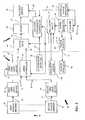
- FIG. 2is a schematic block diagram of a propulsion device, shown on the right, and a control system, shown on the left, for the propulsion device;
- FIG. 3is a schematic diagram showing a preferred embodiment input system of the control system of FIG. 2;
- FIG. 4is a side elevation view taken along line 4 — 4 of FIG. 1 showing an end of the U-shaped handle coupled to one of the load cells and a bail in a raised off position to prevent operation of the propulsion system;
- FIG. 5is a view similar to FIG. 4 showing the handle pushed forward and the bail moved to a lowered on position to permit operation of the propulsion system;
- FIG. 6is a view similar to FIG. 4 showing the handle pulled back and the bail bumped slightly forward to cause a spring to bias the bail to the raised off position;
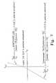
- FIG. 7is a graph depicting the relationship between an input voltage to a gain stage (horizontal axis) and an output voltage to the motor (vertical axis);
- FIG. 8is a perspective view showing a propulsion device including a wheel coupled to a wheel mount, a linear actuator, a pair of links coupled to the linear actuator, a shuttle coupled to one of the links, and a pair of gas springs coupled to the shuttle and the wheel mount;
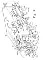
- FIG. 9is an exploded perspective view of various components of the propulsion device of FIG. 8;
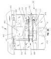
- FIG. 10is a sectional view taken along lines 10 — 10 of FIG. 8 showing the propulsion device with the wheel spaced apart from the floor;
- FIG. 11is a view similar to FIG. 10 showing the linear actuator having a shorter length than in FIG. 10 with the shuttle pulled to the left through the action of the links, and movement of the shuttle moving the wheel into contact with the floor;
- FIG. 12is a view similar to FIG. 10 showing the linear actuator having a shorter length than in FIG. 11 with the shuttle pulled to the left through the action of the links, and additional movement of the shuttle compressing the gas springs;
- FIG. 13is a view similar to FIG. 12 showing the gas springs further compressed as the patient support rides over a “bump” in the floor;
- FIG. 14is a view similar to FIG. 12 showing the gas springs extended as the patient support rides over a “dip” in the floor to maintain contact of the wheel with the floor;
- FIG. 15is a perspective view of a relay switch and keyed lockout switch for controlling enablement of the propulsion device showing a pin coupled to the bail spaced apart from the relay switch to enable the propulsion device;
- FIG. 16is a view similar to FIG. 15 showing the pin in contact with the relay switch to disable the propulsion device from operating;
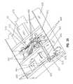
- FIG. 17is a perspective view of a second embodiment hospital bed showing the bed including a bedframe, a second embodiment propulsion device coupled to the bottom of the bedframe, and a pair of spaced-apart handles coupled to the bedframe through a pair of load cells for controlling the propulsion device;
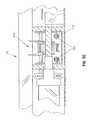
- FIG. 18is a perspective view showing the second embodiment propulsion device including a traction belt supported by a belt mount, an actuator, an arm coupled to the actuator, and a biasing device coupled to the arm and the belt mount;
- FIG. 19is a top plan view of the of the propulsion device of FIG. 18;
- FIG. 20is a detail view of FIG. 19;
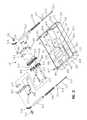
- FIG. 21is an exploded perspective view of the propulsion device of FIG. 18;
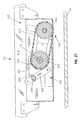
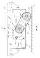
- FIG. 22is a sectional view taken along lines 22 — 22 of FIG. 19 showing the second embodiment propulsion device of FIG. 18 with the track drive spaced apart from the floor;
- FIG. 23is a view similar to FIG. 22 showing the biasing device moved to the left through action of the arm, thereby moving the traction belt into contact with the floor;
- FIG. 24is a view similar to FIG. 22 showing the biasing device moved further to the left than in FIG. 23 through action of the arm, and additional movement of the biasing device compressing a spring received within a tubular member;
- FIG. 25is a view similar to FIG. 24 showing the spring further compressed as the patient support rides over a “bump” in the floor;
- FIG. 26is a view showing the spring extended from its position in FIG. 24 as the patient support rides over a “dip” in the floor to maintain contact of the traction belt with the floor;
- FIG. 27is a sectional view taken along lines 27 — 27 of FIG. 19 showing the second embodiment propulsion device of FIG. 18 with the track drive spaced apart from the floor;
- FIG. 28is a view similar to FIG. 27 showing the traction belt in contact with the floor as illustrated in FIG. 24;
- FIG. 29is a sectional view taken along lines 29 — 29 of FIG. 19;
- FIG. 30is a detail view of FIG. 29;
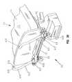
- FIG. 31is a side elevational view of the second embodiment hospital bed of FIG. 17 showing a caster and braking system operably connected to the second embodiment propulsion device;
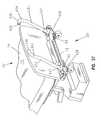
- FIG. 32is view similar to FIG. 31 showing the caster and braking system in a steer mode of operation whereby the traction belt is lowered to contact the floor;
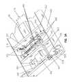
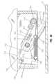
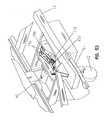
- FIG. 33is a partial perspective view of the second embodiment hospital bed of FIG. 17, with portions broken away, showing the second embodiment propulsion device;
- FIG. 34is a perspective view of the second embodiment propulsion device of FIG. 17 showing the track drive spaced apart from the floor as in FIG. 22;
- FIG. 35is a view similar to FIG. 34 showing the traction belt in contact with the floor as in FIG. 24;
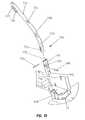
- FIG. 36is a partial perspective view of the second embodiment hospital bed of FIG. 17 as seen from the front and right side, showing a second embodiment input system;
- FIG. 37is a perspective view similar to FIG. 36 as seen from the front and left side;
- FIG. 38is an enlarged partial perspective view of the second embodiment input system of FIG. 36 showing an end of a first handle coupled to a load cell;
- FIG. 39is a sectional view taken along line 39 — 39 of FIG. 38;
- FIG. 40is an exploded perspective view of the first handle of the second embodiment input system of FIG. 38;
- FIG. 41is a perspective view of a third embodiment hospital bed showing the bed including a bedframe, a third embodiment propulsion device coupled to the bottom of the bedframe, and a pair of spaced-apart handles coupled to the bedframe and controlling the propulsion device;
- FIG. 42is a perspective view showing the third embodiment propulsion device including a traction belt supported by a belt mount, an actuator, an arm coupled to the actuator, and a spring coupled to the arm and the belt mount;
- FIG. 43is a top plan view of the of the propulsion device of FIG. 42;
- FIG. 44is a detail view of FIG. 43;
- FIG. 45is an exploded perspective view of the propulsion device of FIG. 42;
- FIG. 46is a sectional view taken along lines 46 — 46 of FIG. 43 showing the alternative embodiment propulsion device of FIG. 42 with the track drive spaced apart from the floor;
- FIG. 47is a view similar to FIG. 46 showing the spring moved to the left through action of the arm, thereby moving the traction belt into contact with the floor;
- FIG. 48is a view similar to FIG. 46 showing the spring moved further to the left than in FIG. 47 through action of the arm, and additional movement of the spring placing the spring in tension;
- FIG. 49is a sectional view taken along lines 49 — 49 of FIG. 43;
- FIG. 50is a detail view of FIG. 49;
- FIG. 51is a side elevational view of the alternative embodiment hospital bed of FIG. 41 showing a caster and braking system operably connected to the third embodiment propulsion device;
- FIG. 52is view similar to FIG. 51 showing the caster and braking system in a steer mode of operation whereby the traction belt is lowered to contact the floor;
- FIG. 53is a partial perspective view of the third embodiment hospital bed of FIG. 41, with portions broken away, showing the third embodiment propulsion device;
- FIG. 54is a perspective view of the third embodiment propulsion device of FIG. 42 showing the track drive spaced apart from the floor as in FIG. 46;
- FIG. 55is a view similar to FIG. 54 showing the traction belt in contact with the floor as in FIG. 48;
- FIG. 56is a partial perspective view of the third embodiment hospital bed of FIG. 42 as seen from the front and right side, showing a third embodiment input system;
- FIG. 57is a perspective view similar to FIG. 56 as seen from to front and left side;
- FIG. 58is a detail view of the charge indicator of FIG. 57;
- FIG. 59is an enlarged partial perspective view of the third embodiment input system of FIG. 56 showing a lower end of a first handle supported by the bedframe;
- FIG. 60is a sectional view taken along line 60 — 60 of FIG. 59;
- FIG. 61is an exploded perspective view of the first handle of the third embodiment input system of FIG. 59.
- FIG. 62is a partial end elevational view of the third embodiment input system of FIG. 56 showing selective pivotal movement of the first handle.
- FIG. 1A patient support or bed 10 in accordance with an illustrative embodiment of the present disclosure is shown in FIG. 1 .
- Patient support 10includes a bedframe 12 extending between opposing ends 9 and 11 , a mattress 14 positioned on bedframe 12 to define a patient rest surface 15 , and an illustrative embodiment propulsion system 16 coupled to bedframe 12 .
- Propulsion system 16is provided to assist a caregiver in moving bed 10 between various rooms in a care facility.
- propulsion system 16includes a propulsion device 18 and an input system 20 coupled to propulsion device 18 .
- Input system 20is provided to control the speed and direction of propulsion device 18 so that a caregiver can direct patient support 10 to the proper position in the care facility.
- Patient support 10includes a plurality of casters 22 that are normally in contact with floor 24 .
- a caregivermay move patient support 10 by pushing on bedframe 12 so that casters 22 move along floor 24 .
- the casters 22may be of the type disclosed in U.S. Pat. No. 6,321,878 to Mobley et al., and in PCT published application No. WO 00/51830 to Mobley et al., both of which are assigned to the assignee of the present invention, and the disclosures of which are expressly incorporated by reference herein.
- propulsion device 18is activated by input system 20 to power patient support 10 so that the caregiver does not need to provide all the force and energy necessary to move patient support 10 between locations in a care facility.
- a suitable propulsion system 16includes a propulsion device 18 and an input system 20 .
- Propulsion device 18includes a traction device 26 that is normally in a storage position spaced apart from floor 24 .
- Propulsion device 18further includes a traction engagement controller 28 .
- Traction engagement controller 28is configured to move traction device 26 from the storage position spaced apart from the floor 24 to a use position in contact with floor 24 so that traction device 26 can move patient support 10 .
- propulsion system 16is implemented in any number of suitable configurations, such as hydraulics, pneumatics, optics, or electrical/electronics technology, or any combination thereof such as hydro-mechanical, electromechanical, or opto-electric embodiments.
- propulsion system 16includes mechanical, electrical and electro-mechanical components as discussed below.
- Input system 20includes a user interface or handle 30 , a first user input device 32 , a second user input device 34 , a third user input device 35 , and a speed controller 36 .
- Handle 30has a first handle member 38 that is coupled to first user input device 32 and second handle member 40 that is coupled to second user input device 34 .
- Handle 30is configured in any suitable manner to transmit a first input force 39 from first handle member 38 to first user input device 32 and to transmit a second input force 41 from second handle member 40 to second user input device 34 . Further details regarding the mechanics of a first embodiment of handle 30 are discussed below in connection with FIGS. 1 and 4 - 6 . Details of additional embodiments of handle 30 are discussed below in connection with FIGS. 36-40, 59 , 60 and 62 - 65 .
- first and second user input devices 32 , 34are configured in any suitable manner to receive the first and second input forces 39 and 41 , respectively, from first and second handle members 38 , 40 , respectively, and to provide a first force signal 43 based on the first input force 39 and a second force signal 45 based on the second input force 41 .
- speed controller 36is coupled to first user input device 32 to receive the first force signal 43 therefrom and is coupled to second user input device 34 to receive the second force signal 45 therefrom.
- speed controller 36is configured in any suitable manner to receive the first and second force signals 43 and 45 , and to provide a speed control signal 46 based on the combination of the first and second force signals 43 and 45 . Further details regarding a preferred embodiment of speed controller 36 are discussed below in connection with FIG. 3 .
- propulsion system 16includes propulsion device 18 having traction device 26 configured to contact floor 24 to move bedframe 12 from one location to another.
- Propulsion device 18further includes a motor 42 coupled to traction device 26 to provide power to traction device 26 .
- Propulsion device 18also includes a motor drive 44 , a power reservoir 48 , a charger 49 and an external power input 50 .
- Motor drive 44is coupled to speed controller 36 of input system 20 to receive speed control signal 46 therefrom.
- Third user input, or enabling, device 35is also coupled to motor drive 44 as shown in FIG. 2 .
- third user input device 35is configured to receive an enable/disable command 51 from a user and to provide an enable/disable signal 52 to motor drive 44 .
- motor drive 44reacts by responding to any speed control signal 46 received from the speed controller 36 .
- a disable command 51 bto third user input 35
- motor drive 44reacts by not responding to any speed control signal 46 received from the speed controller 36 .
- third user input device 35may be configured to receive an enable/disable command 51 from a user and to provide an enable/disable signal 52 to traction engagement controller 28 .
- the traction engagement controller 28responds by placing traction device 26 in the use position in contact with floor 24 .
- traction engagement controller 28responds by placing traction device 26 in its storage position raised above floor 24 .
- motor drive 44is configured in any suitable manner to receive the speed control signal 46 and to provide drive power 53 based on the speed control signal 46 .
- the drive power 53is a power suitable to cause motor 42 to operate at a suitable horsepower 47 (“motor horsepower”).
- motor drive 44is a commercially available Curtis PMC Model No. 1208, which responds to a voltage input range from roughly 0.3 VDC (for full reverse motor drive) to roughly 4.7 VDC (for full forward motor drive) with roughly a 2.3-2.7 VDC input null reference/deadband (corresponding to zero motor speed).
- Motor 42is coupled to motor drive 44 to receive the drive power 53 therefrom.
- Motor 42is suitably configured to receive the drive power 53 and to provide the motor horsepower 47 in response thereto.
- Traction engagement controller 28is configured to provide actuation force to move traction device 26 into contact with floor 24 or away from floor 24 into its storage position. Additionally, traction engagement controller 28 is coupled to power reservoir 48 to receive a suitable operating power therefrom. Traction engagement controller 28 is also coupled to a caster mode detector 54 and to an external power detector 55 for receiving caster mode and external power signals 56 and 57 , respectively. In general, traction engagement controller 28 is configured to automatically cause traction device 26 to lower into its use position in contact with floor 24 upon receipt of both signals 56 and 57 indicating that the casters 22 are in a steer mode of operation and that no external power 50 is applied to the propulsion system 16 . Likewise, traction engagement controller 28 is configured to raise traction device 26 away from contact with floor 24 and into its storage position when the externally generated power is being received through the external power input 50 , or when casters 22 are not in a steer mode of operation.
- the caster mode detector 54is configured to cooperate with a caster and braking system 58 including the plurality of casters 22 supported by bed frame 12 .
- each caster 22includes a wheel 59 rotatably supported by caster forks 60 .
- the caster forks 60are supported for swiveling movement relative to bedframe 12 .
- Each caster 22includes a brake mechanism (not shown) to inhibit the rotation of wheel 59 , thereby placing caster 22 in a brake mode of operation.
- each caster 22includes an anti-swivel or directional lock mechanism (not shown) to prevent swiveling of caster forks 60 , thereby placing caster 22 in a steer mode of operation.
- a neutral mode of operationis defined when neither the brake mechanism nor the directional lock mechanism are actuated such that wheel 59 may rotate and caster forks 60 may swivel.
- the caster and braking system 58also includes an actuator including a plurality of pedals 61 , each pedal 61 adjacent to a different one of the plurality of casters 22 for selectively placing caster and braking system 58 in one of the three different modes of operation: brake, steer, or neutral.
- a linkage 63couples all of the actuators of casters 22 so that movement of any one of the plurality of pedals 61 causes movement of all the actuators, thereby simultaneously placing all of the casters 22 in the same mode of operation. Additional details regarding the caster and braking system 58 are provided in U.S.
- caster mode detector 54includes a tab or protrusion 65 supported by, and extending downwardly from, linkage 63 of caster and braking system 58 .
- a limit switch 67is supported by bedframe 12 wherein tab 65 is engagable with switch 67 .
- a neutral mode of casters 22is illustrated in FIG. 31 when pedal 61 is positioned substantially horizontal. By rotating the pedal 61 counterclockwise in the direction of arrow 166 and into the position as illustrated in phantom in FIG. 31, pedal 61 is placed into a brake mode where rotation of wheels 59 is prevented. In either the neutral or brake modes, the tab 65 is positioned in spaced relation to the switch 67 such that the traction engagement controller 28 does not lower traction device 26 from its storage position into its use position.
- FIG. 32illustrates casters 22 in a steer mode of operation where pedal 61 is positioned clockwise, in the direction of arrows 160 , from the horizontal neutral position of FIG. 31 .
- wheels 59may rotate, but forks 60 are prevented from swiveling.
- linkage 63is moved to the right in the direction of arrow 234 in FIG. 32 .
- tab 65moves into engagement with switch 67 whereby caster mode signal 56 supplied to traction engagement controller 28 indicates that casters 22 are in the steer mode.
- traction engagement controller 28automatically lowers the traction device 26 from its storage position into its use position in contact with the floor 24 .
- the external power detector 55is configured to detect alternating current (AC) since this is the standard current supplied from conventional external power sources.
- the power reservoir 48supplies direct current (DC) to traction engagement controller 28 , speed controller 36 , and motor drive 44 .
- DCdirect current
- external power detector 55by sensing the presence of AC current, provides an indication of the connection of an external power source through power input 50 to the propulsion system 16 .
- the traction engagement controller 28is configured to (i) activate an actuator to raise traction device 26 when casters 22 are not in a steer mode of operation as detected by caster mode detector 54 ; and (ii) activate an actuator to raise traction device 26 when externally generated power is received through external power input 50 as detected by external power detector 55 .
- the linear actuator in the embodiment of FIGS. 8-14is normally extended (i.e., the linear actuator includes a spring (not shown) which causes it to be in the extended state when it receives no power). Retraction of the linear actuator provides actuation force which moves traction device 26 into contact with floor 24 , while extension of the linear actuator removes the actuation force and moves traction device 26 away from floor 24 .
- traction engagement controller 28inhibits contact of traction device 26 with floor 24 not only when the user places casters 22 of bed 10 in brake or neutral positions, but also when charger 48 is plugged into an external power line through input 50 .
- Power reservoir 48is coupled to speed controller 36 of input system 20 and motor drive 44 and traction engagement controller 28 of propulsion system 16 to provide the necessary operating power thereto.
- power reservoir 48includes two rechargeable 12 AmpHour 12 Volt type 12120 batteries connected in series which provide operating power to motor drive 44 , motor 42 , and the linear actuator in traction engagement controller 28 , and further includes an 8.5 V voltage regulator which converts unregulated power from the batteries into regulated power for electronic devices in propulsion system 16 (such as operational amplifiers).
- power reservoir 48may be suitably coupled to other components of propulsion system 16 in other embodiments, and may be accordingly configured as required to provide the necessary operating power.
- Charger 49is coupled to external power input 50 to receive an externally generated power therefrom, and is coupled to power reservoir 48 to provide charging thereto. Accordingly, charger 49 is configured to use the externally generated power to charge, or replenish, power reservoir 48 .
- charger 49is an IBEX model number L24-1.0/115AC.
- External power input 50is coupled to charger 49 and traction engagement controller 28 to provide externally generated power thereto.
- the external power input 50is a standard 115V AC power plug.
- a charge detector 69is provided in communication with power reservoir 48 for sensing the amount of power or charge contained therein.
- the amount of detected chargeis provided to a charge indicator 70 through a charge indication signal 71 .
- the charge indicator 70may comprise any conventional display visible to the caregiver.
- One embodiment, as illustrated in FIG. 58comprises a plurality of lights 72 , preferably light emitting diodes (LEDs), which provide a visible indication of remaining charge in the power reservoir 48 .
- Each illuminated LED 72is representative of a percentage of full charge remaining, such that the fewer LEDs illuminated, the less charge remains within power reservoir 48 .
- the charge indicator 70may comprise other similar displays, including, but not limited to liquid crystal displays.
- a shut down relay 77is provided in communication with the charge detector 69 .
- the charge detector 69senses a remaining charge within the power reservoir 48 below a predetermined amount, it sends a low charge signal 74 to the shut down relay 77 .
- the predetermined amountis defined as seventy percent of a full charge.
- the shut down relay 77in response to the low charge signal 74 , disconnects the power reservoir 48 from the motor drive 44 and the traction engagement controller 28 . As such, further depletion of the power reservoir 48 is prevented. Preventing the unnecessary depletion of the power reservoir 48 typically extends the useful life of the batteries within the power reservoir 48 .
- the shut down relay 77is in further communication with a manual shut down switch 100 .
- the shut down switch 100may comprise a conventional toggle switch supported by the bedframe 12 and physically accessible to the user. As illustrated in FIGS. 42 and 45, the switch 100 may be positioned behind a wall 101 formed by traction device 26 such that access is available only through an elongated slot 102 , thereby preventing inadvertent movement of the switch 100 .
- the switch 100causes shut down relay 77 to disconnect power from motor drive 44 and traction engagement controller 28 which is desirable during shipping and maintenance of patient support 10 .
- the propulsion device 18is configured to be manually pushed should the traction device 26 be in the lowered use position and power is no longer available to drive the motor 42 and traction engagement controller 28 .
- the motor 42is geared to permit it to be backdriven.
- it is preferred that the no more than 200% of manual free forceis required to push the bed 10 when the traction device 76 is lowered to the use position, compared to when the traction device 26 is raised to the storage position.
- traction engagement controller 28does not provide the actuation force to lower traction device 26 into contact with floor 24 unless the user disconnects external power input 50 from the power line and places casters 22 in a steer mode of operation through pedal 61 .
- Propulsion system 16 of FIG. 2operates generally in the following manner.
- the userfirst disconnects external power 50 from the patient support 10 and then places casters 22 in a steer mode through pivoting movement of pedal 61 in a clockwise direction.
- traction engagement controller 28lowers traction device 26 to floor 24 .
- the userthen activates the third user, or enabling, device 35 by providing an enabling command 51 thereto.
- the userapplies force to handle 30 so that propulsion system 16 receives the first input force 39 and the second input force 41 from first and second handle members 38 , 40 , respectively.
- the motor 42provides motor horsepower 47 to traction device 26 based on first input force 39 and second input force 41 .
- a userselectively applies a desired amount of motor horsepower 47 to traction device 26 by imparting a selected amount of force on handle 30 . It should be readily appreciated that in this manner, the user causes patient support 10 of FIG. 1 to “self-propel” to the extent that the user applies force to handle 30 .
- first input force 39 , second input force 41 , motor horsepower 47 , and actuation force 104generally are each signed quantities; that is, each may take on a positive or a negative value with respect to a suitable neutral reference.
- pushing on first handle member 38 of propulsion system 16 in forward direction 23as shown in FIG. 5 for handle 30 , generates a positive first input force 39 with respect to a neutral reference position, as shown in FIG. 4 for handle 30
- pulling on first end 38 in direction 25as shown in FIG. 6 for preferred handle 30
- the deflection shown in FIGS. 5 and 6is exaggerated for illustration purposes only. In actual use, the deflection of the handle 30 is very slight.
- first force signal 43 from first user input device 32 and second force signal 45 from second user input device 34are each correspondingly positive or negative with respect to a suitable neutral reference, which allows speed controller 36 to provide a correspondingly positive or negative speed control signal to motor drive 44 .
- Motor drive 44then in turn provides a correspondingly positive or negative drive power to motor 42 .
- a positive drive powercauses motor 42 to move traction device 26 in a forward direction
- the negative drive powercauses motor 42 to move traction device 26 in an opposite reverse direction.
- the speed controller 36is configured to instruct motor drive 44 to power motor 42 at a reduced speed in a reverse direction as compared to a forward direction.
- the negative drive power 53 ais approximately one-half the positive drive power 53 b .
- the maximum forward speed of patient support 10is between approximately 2.5 and 3.5 miles per hour, while the maximum reverse speed of patient support 10 is between approximately 1.5 and 2.5 miles per hour.
- speed controller 36limits both the maximum forward and reverse acceleration of the patient support 10 in order to promote safety of the user and reduce damage to floor 24 as a result of sudden engagement and acceleration by traction device 26 .
- the speed controller 36limits the maximum acceleration of motor 42 for a predetermined time period upon initial receipt of force signals 43 and 45 by speed controller 36 .
- forward direction accelerationshall not exceed 1 mile per hour per second for the first three seconds and reverse direction acceleration shall not exceed 0.5 miles per hour per second for the first three seconds.
- the preferred embodimentprovides motor horsepower 47 to traction device 26 proportional to the sum of the first and second input forces from first and second ends 38 , 40 , respectively, of handle 30 .
- the preferred embodimentgenerally increases the motor horsepower 47 when a user increases the sum of the first input force 39 and the second input force 41 , and generally decreases the motor horsepower 47 when a user decreases the sum of the first and second input forces 39 and 41 .
- Motor horsepower 47is roughly a constant function of torque and angular velocity. Forces which oppose the advancement of a platform over a plane are generally proportional to the mass of the platform and the incline of the plane.
- the preferred embodimentalso provides a variable speed control for a load bearing platform having a handle 30 for a user and a motor-driven traction device 26 .
- a load bearing platformhaving a handle 30 for a user and a motor-driven traction device 26 .
- a load bearing platformhaving a handle 30 for a user and a motor-driven traction device 26 .
- the userpushes handle 30 of propulsion system 16 (see FIG. 2 ), and thus imparts a particular first input force 39 to first user input device 32 and a particular second input force 41 to second user input device 34 .
- the torque component of the motor horsepower 47 provided to traction device 26assists the user in overcoming the forces which oppose advancement of patient support 10 , while the speed component of the motor horsepower 47 ultimately causes patient support 10 to travel at a particular speed.
- the usercauses patient support 10 to travel at a higher speed by imparting greater first and second input forces 39 and 41 through handle 30 (i.e., by pushing harder) and vice-versa.
- handle 30 and the remainder of input system 20 and the resulting propulsion of patient support 10 propelled by traction device 26provide inherent feedback (not shown) to propulsion system 16 which allows the user to easily cause patient support 10 to move at the pace of the user so that propulsion system 16 tends not to “outrun” the user.
- propulsion system 16tends not to “outrun” the user.
- patient support 10moves faster than the user which, in turn, tends to reduce the pushing force applied on handle 30 by the user.
- patient support 10tends to automatically match the pace of the user.
- the preferred embodimentalso provides coordination between the user and patient support 10 propelled by traction device 26 by varying the motor horsepower 47 with differential forces applied to handle 30 , such as are applied by a user when pushing or pulling patient support 10 around a corner.
- the typical manner of negotiating a turninvolves pushing on one end of handle 30 with greater force than on the other end, and for sharp turns, typically involves pulling on one end while pushing on the other.
- the forces applied to first end 38 and second end 40 of handle 30are roughly equal in magnitude and both are positive; but when the user negotiates a turn, the sum of the first force signal 43 and the second force signal 45 is reduced, which causes reduced motor horsepower 47 to be provided to traction device 26 .
- This reduces the motor horsepower 47 provided to traction device 26which in turn reduces the velocity of patient support 10 , which in turn facilitates the negotiation of the turn.
- a second traction devicemay be provided and driven independently from the first traction device 26 .
- the second traction devicewould be laterally offset from the first traction device 26 .
- the horsepower provided to the second traction devicewould be weighted in favor of the second force signal 45 to further facilitate negotiating of turns.
- FIG. 3is an electrical schematic diagram showing selected aspects of the preferred embodiment of input system 20 of propulsion system 17 of FIG. 2 .
- FIG. 3depicts a first load cell 62 , a second load cell 64 , and a summing control circuit 66 .
- Regulated 8.5 V power (“Vcc”) to these componentsis supplied by the preferred embodiment of power reservoir 48 as discussed above in connection with FIG. 2 .
- First load cell 62includes four strain gauges illustrated as resistors: gauge 68 a , gauge 68 b , gauge 68 c , and gauge 68 d . As shown in FIG. 3, these four gauges 68 a , 68 b , 68 c , 68 d are electrically connected within load cells 62 , 64 to form a Wheatstone bridge.
- each of the load cells 62 , 64is a commercially available HBM Co. Model No. MED-400 06101.
- These load cells 62 , 64 of FIG. 3are the preferred embodiment of first and second user input devices 32 , 34 of FIG. 2 .
- the user inputsare other elastic or sensing elements configured to detect the force on the handle, deflection of the handle, or other position or force related characteristics.
- Vccis electrically connected to node A of the bridge, ground (or common) is applied to node B, a signal S 1 is obtained from node C, and a signal S 2 is obtained from node D.
- the power to second load cell 64is electrically connected in like fashion to first load cell 62 .
- nodes E and F of second load cell 64correspond to nodes A and B of first load cell 62
- nodes G and H of second load cell 64correspond to nodes C and D of first load cell 62 .
- signal S 3 (at node G) and signal S 4 (at node H)are electrically connected to summing control circuit 66 in reverse polarity as compared to the corresponding respective signals S 1 and S 2 .
- Summing control circuit 66 of FIG. 3is the preferred embodiment of the speed controller 36 of FIG. 2 . Accordingly, it should be readily appreciated that a first differential signal (S 1 -S 2 ) from first load cell 62 is the preferred embodiment of the first force signal 43 discussed above in connection with FIG. 2, and, likewise, a second differential signal (S 3 -S 4 ) from second load cell 64 is the preferred embodiment of the second force signal 45 discussed above in connection with FIG. 2 .
- the summing control circuit 66includes a first buffer stage 76 , a second buffer stage 78 , a first pre-summer stage 80 , a second pre-summer stage 82 , a summer stage 84 , and a directional gain stage 86 .
- First buffer stage 76includes an operational amplifier 88 , a resistor 90 , a resistor 92 , and a potentiometer 94 which are electrically connected to form a high input impedance, noninverting amplifier with offset adjustability as shown.
- the noninverting input of operational amplifier 88is electrically connected to node C of first load cell 62 .
- Resistor 90is very small relative to resistor 92 so as to yield practically unity gain through buffer stage 76 . Accordingly, resistor 90 is 1 k ohm, and resistor 92 is 100 k ohm. Potentiometer 94 allows for calibration of summing control circuit 66 as discussed below.
- potentiometer 94is a 20 k ohm linear potentiometer. It should be readily understood that second buffer stage 78 is configured in identical fashion to first buffer stage 76 ; however, the noninverting input of the operational amplifier in the second buffer stage 78 is electrically connected to node H of second load cell 64 as shown.
- First pre-summer stage 80includes an operational amplifier 96 , a resistor 98 , a capacitor 110 , and a resistor 112 which are electrically connected to form an inverting amplifier with low pass filtering as shown.
- the noninverting input of operational amplifier 96is electrically connected to the node D of first load cell 62 .
- Resistor 98 , resistor 112 , and capacitor 110are selected to provide a suitable gain through first pre-summer stage 80 , while providing sufficient noise filtering. Accordingly, resistor 98 is 110 k ohm, resistor 112 is 1 k ohm, and capacitor 110 is 0.1 ⁇ F.
- second pre-summer stage 82is configured in identical fashion to first pre-summer stage 80 ; however, the noninverting input of the operational amplifier in second pre-summer stage 82 is electrically connected to node G of second load cell 64 as shown.
- Summer stage 84includes an operational amplifier 114 , a resistor 116 , a resistor 118 , a resistor 120 , and a resistor 122 which are electrically connected to form a differential amplifier as shown.
- Summer stage 84has a inverting input 124 and a noninverting input 126 .
- Inverting input 124is electrically connected to the output of operational amplifier 96 of first pre-summer stage 80 and noninverting input 126 is electrically connected to the output of the operational amplifier of second pre-summer stage 82 .
- Resistor 116 , resistor 118 , resistor 120 , and resistor 122are selected to provide a roughly balanced differential gain of about 10 .
- resistor 116is 100 k ohm
- resistor 118is 100 k ohm
- resistor 120is 10 k ohm
- resistor 122is 12 k ohm. If an ideal operational amplifier is used in the summer stage, resistors 120 , 122 would have the same value (for example, 12 K ohms) so that both the noninverting and inverting inputs of the summer stage are balanced; however, to compensate for the slight imbalance in the actual noninverting and inverting inputs, resistors 120 , 122 are slightly different in the preferred embodiment.
- Directional gain stage 86includes an operational amplifier 128 , a diode 130 , a potentiometer 132 , a potentiometer 134 , a resistor 136 , and a resistor 138 which are electrically connected to form a variable gain amplifier as shown.
- the noninverting input of operational amplifier 128is electrically connected to the output of operational amplifier 114 of summer stage 84 .
- Potentiometer 132 , potentiometer 134 , resistor 136 , and resistor 138are selected to provide a gain through directional gain stage 86 which varies with the voltage into the noninverting input of operational amplifier 128 generally according to the relationship between the voltage out of operational amplifier 128 and the voltage into the noninverting input of operational amplifier 128 as depicted in FIG. 3 . Accordingly, potentiometer 132 is trimmed to 30 k ohm, potentiometer 134 is trimmed to 30 k ohm, resistor 136 is 22 k ohm, and resistor 138 is 10 k ohm. All operational amplifiers are preferably National Semiconductor type LM258 operational amplifiers.
- the components shown in FIG. 3provide the speed control signal 46 to motor drive 44 generally in the following manner.
- the usercalibrates speed controller 36 (FIG. 2) to provide the speed control signal 46 within limits that are consistent with the configuration of motor drive 44 .
- speed controller 36FIG. 2
- motor drive 44responds to a voltage input range from roughly 0.3 VDC (for full reverse motor drive) to roughly 4.7 VDC (for full forward motor drive) with roughly 2.3-2.7 VDC input null reference/deadband (corresponding to zero motor speed).
- first load cell 62the user adjusts potentiometer 94 of first buffer stage 76 to generate 2.5 V at inverting input 124 of summer stage 84
- second load cell 64the user adjusts the corresponding potentiometer in second buffer stage 78 to generate 2.5 V at noninverting input 126 of summer stage 84 .
- the no load conditionoccurs when the user is neither pushing nor pulling handle 30 as shown in FIGS. 1 and 4.
- a voltage of 2.5 V at inverting input 124 of summer stage 84 and 2.5 V at noninverting input 126 of summer stage 84causes summer stage 84 to generate very close to 0 V at the output of operational amplifier 114 (the input of operational amplifier 128 of the directional gain stage 86 ), which in turn causes directional gain stage 86 to generate a roughly 2.5 V speed control signal on the output of operational amplifier 128 .
- the potentiometers of first and second buffer stages 76 , 78the user ensures that no motor horsepower is generated at no load conditions.
- Calibrationalso includes setting the desirable forward and reverse gains by adjusting potentiometer 132 and potentiometer 134 of directional gain stage 86 .
- diode 130becomes forward biased when the voltage at the noninverting input of operational amplifier 128 begins to drop sufficiently below the voltage at the inverting input of operational amplifier 128 .
- the voltage at the inverting input of operation amplifier 128is roughly 2.5 V as a result of the voltage division of the 8.5 V Vcc between resistor 136 and resistor 138 .
- directional gain stage 86may be calibrated to provide a relatively higher gain for voltages out of differential stage 84 which exceed the approximate 2.5 V null reference/deadband of motor drive 44 than it provides for voltages out of differential stage 84 which are less than roughly 2.5 V.
- the usercalibrates directional gain stage 86 by adjusting potentiometer 132 and potentiometer 134 as desired to generate more motor horsepower per unit force on handle 30 in the forward direction than in the reverse direction.
- Patient supportsare often constructed such that they are more easily moved by pulling them in reverse than by pushing them forward.
- the variable gain calibration features provided in directional gain stage 86tend to compensate for the directional difference.
- traction engagement controller 28provides an actuation force 104 which causes a preferred embodiment of traction device 26 to contact floor 24 .
- the userinputs an enable command through third user input device 35 (activates a switch).
- first handle member 38 and/or second handle member 40which imparts a first input force 39 to first load cell 62 and/or a second input force 41 to second load cell 64 , causing a first differential signal (S 1 -S 2 ) and/or a second differential signal (S 3 -S 4 ) to be transmitted to first pre-summer stage 80 and/or second pre-summer stage 82 , respectively.
- summer stage 84effectively inverts the output of second pre-summer stage 82 , which provides that the signs of the forces imparted to first member 38 and second member 40 of handle 30 are ultimately actually consistent relevant to the actions of pushing and/or pulling patient support 10 of FIG. 1 .
- First buffer stage 76 and second buffer stage 78facilitate obtaining first differential signal (S 1 -S 2 ) and second differential signal (S 3 -S 4 ) from first load cell 62 and second load cell 64 .
- the differential signals from the Wheatstone bridges of load cells 62 , 64reject signals which might otherwise be undesirably generated by torsional type pushing or pulling on members 38 , 40 of handle 30 .
- the usercan increase the magnitude of the sum of the forces imparted to first and second handle members 38 , 40 , respectively, to increase the speed control signal 46 or decrease the magnitude of the sum to decrease the speed control signal 46 .
- These changes in the speed control signal 46cause traction device 26 to propel patient support 10 in either the forward or reverse direction as desired.
- the input systems of the present disclosuremay be used on motorized support frames other than beds.
- the input systemmay be used on carts, pallet movers, or other support frames used to transport items from one location to another.
- each load cell 62 , 64is directly coupled to bedframe 12 by a bolt 140 extending through a plate 142 of bedframe 12 into each load cell 62 , 64 .
- First and second handle members 38 , 40 of handle 30are coupled to respective load cells 62 , 64 by bolts 144 so that handle 30 is coupled to bedframe 12 through load cells 62 , 64 .
- FIGS. 1, 4 - 6 , 15 , and 16An embodiment of third user input device 35 is shown in FIGS. 1, 4 - 6 , 15 , and 16 .
- Input device 35includes a bail 75 pivotally coupled to a lower portion of handle 30 , a spring mount 73 coupled to first handle member 38 of handle 30 , a pair of loops 79 , 81 coupled to bail 75 , and a spring 83 coupled to spring mount 73 and loop 79 .
- Bail 75 and loops 79 , 81are pivotable between an on/enable position, shown in FIGS. 5 and 6, and an off/disable position as shown in FIG. 4 .
- User input device 35further includes a pair of pins 89 coupled to handle 30 to limit the range of motion of loops 79 , 81 and bail 75 .
- the weight of bail 75acts against the bias provided by spring 83 .
- spring 83with the assistance of said force will pull bail 75 to the off/disable position to shut down propulsion system 16 .
- spring 83is coupled to the upper arm of loop 79 .
- User input device 35further includes a relay switch 85 positioned adjacent a pin 97 coupled to first end 87 of bail 75 and a keyed lockout switch 93 coupled to plate 142 as shown in FIG. 15 .
- Relay switch 85 and keyed lockout switch 93are coupled in series to provide the enable and disable commands.
- Keyed lockout switch 93must be turned to an on position by a key 95 for an enable command and relay switch must be in a closed position for an enable command.
- pin 97moves switch 85 to an open position to generate a disable command.
- bail 75moves to the enable position as shown in FIG.
- pin 97moves away from switch 85 to permit switch 85 to move to the closed position to generate an enable command when keyed lockout switch 93 is in the on position permitting lowering of the preferred embodiment of traction device 26 into contact with floor 24 .
- traction device 26will not lower into contact with floor 24 .
- User input device 35further includes a pair of pins 89 coupled to handle 30 to limit the range of motion of loops 79 , 81 and bail 75 .
- the weight of bail 75acts against the bias provided by spring 83 .
- spring 83with the assistance of said force will pull bail 75 to the off/disable position to shut down propulsion system 16 .
- bail 75will flip to the off/disable position to disable use of propulsion system 16 .
- propulsion device 18will not operate.
- Propulsion device 18includes a preferred embodiment traction device 26 comprising a wheel 150 , a preferred embodiment traction engagement controller 28 comprising a wheel lifter 152 , and a chassis 151 coupling wheel lifter 152 to bedframe 12 .
- traction device 26comprising a wheel 150
- traction engagement controller 28comprising a wheel lifter 152
- chassis 151coupling wheel lifter 152 to bedframe 12 .
- other traction devices or rolling supportssuch as multiple wheel devices, track drives, or other devices for imparting motion to a patient support are used as the traction device.
- other configurations of traction engagement controllersare provided, such as the wheel lifter described in U.S. Pat. Nos.
- Wheel lifter 152includes a wheel mount 154 coupled to chassis 151 and a wheel mount mover 156 coupled to wheel mount 154 and chassis 151 at various locations.
- Motorized wheel 150is coupled to wheel mount 154 as shown in FIG. 8 .
- Wheel mount mover 156is configured to pivot wheel mount 154 and motorized wheel 150 about a pivot axis 158 to move motorized wheel 150 between storage and use positions as shown in FIGS. 10-12.
- Wheel mount 154is also configured to permit motorized wheel 150 to raise and lower during use of patient support 10 to compensate for changes in elevation of patient support 10 .
- wheel mount 154 and wheel 150may pivot in a clockwise direction 160 about pivot axis 158 when bedframe 12 moves over a bump in floor 24 .
- wheel mount 154 and motorized wheel 150are configured to pivot about pivot axis 158 in a counterclockwise 166 direction when bedframe 12 moves over a recess in floor 24 as shown in FIG. 14 .
- wheel mount 154is configured to permit motorized wheel 150 to remain in contact with floor 24 during changes in elevation of floor 24 relative to patient support 10 .
- Wheel mount 154is also configured to provide the power to rotate motorized wheel 150 during operation of propulsion system 16 .
- Wheel mount 154includes a motor mount 170 coupled to chassis 151 and a preferred embodiment electric motor 172 coupled to motor mount 170 as shown in FIG. 8 .
- motor 172is a commercially available Groschopp Iowa Permanent Magnet DC Motor Model No. MM8018.
- Motor 172includes a housing 178 and an output shaft 176 and a planetary gear (not shown). Motor 172 rotates shaft 176 about an axis of rotation 180 and motorized wheel 150 is directly coupled to shaft 176 to rotate about an axis of rotation 182 that is coaxial with axis of rotation 180 of output shaft 176 . Axes of rotation 180 , 182 are transverse to pivot axis 158 .
- wheel mount mover 156further includes an illustrative embodiment linear actuator 184 , a linkage system 186 coupled to actuator 184 , a shuttle 188 configured to slide horizontally between a pair of rails 190 and a plate 191 , and a pair of gas springs 192 coupled to shuttle 188 and wheel mount 154 .
- Linear actuator 184is illustratively a Linak model number LA12.1-100-24-01 linear actuator.
- Linear actuator 184includes a cylinder body 194 pivotally coupled to chassis 151 and a shaft 196 telescopically received in cylinder body 194 to move between a plurality of positions.
- Linkage system 186includes a first link 198 and a second link 210 coupling shuttle 188 to actuator 184 .
- First link 198is pivotably coupled to shaft 196 of actuator 184 and pivotably coupled to a portion 212 of chassis 151 .
- Second link 210is pivotably coupled to first link 198 and pivotably coupled to shuttle 188 .
- Shuttle 188is positioned between rails 190 and plate 191 of chassis 151 to move horizontally between a plurality of positions as shown in FIGS. 10-12.
- each of gas springs 192include a cylinder 216 pivotably coupled to shuttle 188 and a shaft 218 coupled to a bracket 220 of wheel mount 154 .
- the linear actuatoris directly coupled to the shuttle.
- Actuator 184is configured to move between an extended position as shown in FIG. 10 and a retracted position as shown in FIGS. 12-14. Movement of actuator 184 from the extended to retracted position moves first link 198 in a clockwise direction 222 . This movement of first link 198 pulls second link 210 and shuttle 188 to the left in direction 224 as shown in FIG. 11 . Movement of shuttle 188 to the left in direction 224 pushes gas springs 192 downward and to the left in direction 228 and pushes a distal end 230 of wheel mount 154 downward in direction 232 as shown in FIG. 11 .
- linear actuator 184continues to retract so that shuttle 188 continues to move to the left in direction 224 .
- This continued movement of shuttle 188 and the contact of motorized wheel 150 with floor 24causes gas springs 192 to compress so that less of shaft 218 is exposed, as shown in FIG. 12, until linear actuator 184 reaches a fully retracted position.
- This additional movementcreates compression in gas springs 192 so that gas springs 192 are compressed while wheel 150 is in the normal use position with bedframe 12 at a normal distance from floor 24 .
- This additional compressioncreates a greater normal force between floor 24 and wheel 150 so that wheel 150 has increased traction with floor 24 .
- bedframe 12will move to different elevations relative to floor 24 during transport of patient support 10 from one position in the care facility to another position in the care facility. For example, when patient support 10 is moved up or down a ramp, portions of bedframe 12 will be at different positions relative to floor 24 when opposite ends of patient support 10 are positioned on and off of the ramp. Another example is when patient support 10 is moved over a raised threshold or over a depression in floor 24 , such as a utility access plate (not shown).
- gas springs 192creates a downward bias on wheel mount 154 in direction 232 so that when bedframe 12 is positioned over a “recess” in floor 24 , gas springs 192 move wheel mount 154 and wheel 150 in clockwise direction 160 so that wheel 150 remains in contact with floor 24 .
- the weight of patient support 10will compress gas springs 192 so that wheel mount 154 and motorized wheel 150 rotate in counterclockwise direction 166 relative to chassis 151 and bedframe 12 , as shown for example, in FIG. 14 .
- actuator 184moves to the extended position as shown in FIG. 10 .
- shuttle 188is pushed to the right in direction 234 .
- the compression in gas springs 192is gradually relieved until shafts 196 of gas springs 192 are completely extended and gas springs 192 are in tension.
- the continued movement of shuttle 188 in direction 234causes gas springs 192 to raise motor mount 154 and wheel 150 to the raised position shown in FIG. 10 .
- the compression of gas springs 192assists in raising wheel 150 .
- actuator 184requires less energy and force to raise wheel 150 than to lower wheel 150 .
- Chassis 151includes a chassis body 250 , a bracket 252 coupled to chassis body 250 and bedframe 12 , an aluminum pivot plate 254 coupled to chassis body 250 , a pan 256 coupled to a first arm 258 of chassis body 250 , a first rail member 260 , a second rail member 262 , a containment member 264 , a first stiffening plate 266 coupled to second rail member 262 , a second stiffening plate 268 coupled to first rail member 260 , and an end plate 270 coupled to bedframe 12 and first and second rail members 260 , 262 .
- Wheel mount 154further includes a first bracket 272 pivotably coupled to chassis body 250 and pivot plate 254 , an extension body 274 coupled to bracket 272 and motor 172 , and a second bracket 276 coupled to motor 172 .
- Wheel 150includes a wheel member 278 having a central hub 280 and a pair of locking members 282 , 284 positioned on each side of central hub 280 .
- first locking member 282is positioned over shaft 176
- wheel member 278is positioned over shaft 176
- second locking member 284is positioned over shaft 176 .
- Bolts(not shown) are used to draw first and second locking members 282 , 284 together.
- Central hub 280has a slight taper and inner surfaces of first and second locking members 282 , 284 have complimentary tapers. Thus, as first and second locking members 282 , 284 are drawn together, central hub 280 is compressed to grip shaft 176 of motor 172 to securely fasten wheel 150 to shaft 176 .
- First rail member 260includes first and second vertical walls 286 , 288 and a horizontal wall 290 .
- Vertical wall 286is welded to first arm 258 of chassis body 250 so that an upper edge 292 of first vertical wall 286 is adjacent to an upper edge 294 of first arm 258 .
- second rail member 262includes a first vertical wall 296 , a second vertical wall 298 , and a horizontal wall 310 .
- Second vertical wall 298is welded to a second arm 312 of chassis body 250 so that an upper edge 314 of second vertical wall 298 is adjacent to an upper edge 316 of second arm 312 .
- End plate 270is welded to ends 297 , 299 of first and second rail members 260 , 262 .
- Containment member 264includes a first vertical wall 318 , a second vertical wall 320 , and a horizontal wall 322 .
- Second wall 288 of first rail member 260is coupled to an interior of first vertical wall 318 of containment member 264 .
- first vertical wall 296 of second rail member 262is coupled to an interior of second vertical wall 320 .
- shuttle 188is trapped between horizontal wall 322 and vertical walls 288 , 296 so that vertical walls 288 , 286 define rails 190 and horizontal wall 322 defines plate 191 .
- Wheel lifter 152further includes a pair of bushings 324 having first link 198 sandwiched therebetween.
- a pinpivotally couples bushings 324 and first link 198 to containment member 264 so that containment member 264 defines portion 212 of chassis 151 as shown in FIG. 10 .
- first and second rail members 260 , 262When fully assembled, first and second rail members 260 , 262 include a couple of compartments. Motor controller 326 containing the preferred motor driver circuitry is positioned within first rail member 260 and circuit board 328 containing the preferred input system circuitry and relay 330 are positioned in first rail member 260 .
- Shuttle 188includes a first slot 340 for pivotally receiving an end of second link 210 . Similarly, shuttle 188 includes second and third slots 342 for pivotally receiving ends of gas spring 292 as shown in FIG. 9 .
- Bracket 220is coupled to the second bracket 276 with a deflection guard 334 sandwiched therebetween. Gas springs 292 are coupled to bracket 220 as shown in FIG. 9 .
- a plate 336is coupled to pan 256 to provide a stop that limits forward movement of wheel mount 154 .
- second bracket 276includes an extended portion 338 that provides a second stop for wheel mount 154 that limits backward movement of wheel mount 154 .
- a second embodiment patient support 10 ′is illustrated as including a second embodiment propulsion system 16 ′ coupled to the bedframe 12 in a manner similar to that identified above with respect to the previous embodiment.
- the propulsion system 16 ′operates substantially in the same manner as the first embodiment propulsion system 16 illustrated in FIG. 2 and described in detail above.
- the propulsion system 16 ′includes a propulsion device 18 ′ and an input system 20 ′ coupled to the propulsion device 18 ′.
- the input system 20 ′is provided to control the speed and direction of the propulsion device 18 ′ so that a caregiver may direct the patient support 10 ′ to the proper position in the care facility.
- the input system 20 ′ of the second embodiment patient support 10 ′is substantially the same as the input system 20 of the above-described embodiment as illustrated in FIG. 2 .
- a user interface or handle 430is provided as including first and second handle members 431 and 433 positioned in spaced relation to each other and supported for relative independent movement in response to the application of first and second input forces 39 and 41 .
- the first handle member 431is coupled to a first user input device 32 ′ while the second handle member 433 is coupled to a second user input device 34 ′.
- the handle members 431 and 433are configured to transmit first input force 39 from the first handle member 431 to the first user input device 32 ′ and to transmit second input force 41 from the second handle member 433 to the second user input device 34 ′.
- first and second handle members 431 and 433comprise elongated tubular members 434 extending between opposing upper and lower ends 436 and 437 .
- the upper end 436 of each first and second handle member 431 and 433includes a third user input, or enabling, device 435 , preferably a normally open push button switch requiring continuous depression in order for the motor drive 44 to supply power to the motor 42 .
- the lower end 437 of each first and second handle member 431 and 433is concentrically received within a mounting tube 438 fixed to the bedframe 12 . More particularly, with reference to FIG.
- a pin 440passes through each tubular member 434 and into the sidewalls of the mounting tube 438 in order to secure the first and second handle members 431 and 433 thereto.
- a collar 442may be concentrically received around an upper end of the mounting tube 438 in order to shield the pin 440 .
- a mounting block 443is secured to a lower surface of the bedframe 12 and connects the casters 22 thereto.
- a load cell 62 , 64 of the type described aboveis secured to the mounting block 443 , typically through a conventional bolt 444 , and is in proximity to the lower end 437 of each first and second handle members 431 and 433 .
- Each load cell 62 , 64is physically connected to a lower end of the tubular member 434 by a bolt 444 passing through a slot 446 formed within lower end 437 .
- force applied proximate the upper end 436 of the first and second handle members 431 and 433is transmitted downwardly to the lower end 437 , through the bolt 444 and into the load cell 62 , 64 for operation in the manner described above with respect to FIG. 3 .
- the independent supports and the spaced relationship of the first and second handle members 431 and 433prevent the transmission of forces directly from one handle member 431 to the other handle member 433 .
- the speed controller 36is configured to operate upon receipt of a single force signal 43 or 45 due to application of only a single force 39 or 41 to a single user input device 32 or 34 .
- a lockout key 95is supported on the bedframe 12 proximate the first and second handle members 38 and 40 and may be used to prevent unauthorized operation of the patient support 10 .
- the alternative embodiment propulsion device 18 ′is shown in greater detail in FIGS. 18-30.
- the propulsion device 18 ′includes a rolling support in the form of a drive track 449 having rotatably supported first and second rollers 450 and 452 supporting a track or belt 453 for movement.
- the first roller 450is driven by motor 42 while the second roller 452 is an idler.
- the second embodiment traction engagement controller 28 ′includes a rolling support lifter 454 , and a chassis 456 coupling the rolling support lifter 454 to bed frame 12 .
- the rolling support lifter 454includes a rolling support mount 458 coupled to the chassis 456 and a rolling support mount mover, or simply rolling support mover 460 , coupled to rolling support mount 458 and chassis 456 at various locations.
- the rollers 450 and 452are rotatably supported intermediate side plates 462 and spacer plates 464 forming the rolling support mount 458 .
- the rollers 450 and 452preferably include a plurality of circumferentially disposed teeth 466 for cooperating with a plurality of teeth 468 formed on an inner surface 470 of the belt 453 to provide positive engagement therewith and to prevent slipping of the belt 453 relative to the rollers 450 and 452 .
- Each roller 450 and 452likewise preferably includes a pair of annular flanges 472 disposed near a periphery thereof to assist in tracking or guiding belt 453 in its movement.
- a drive shaft 473extends through the first roller 450 while a bushing 475 is received within the second roller 452 and receives a nondriven shaft 476 .
- a plurality of brackets 477are provided to facilitate connection of the chassis 456 of bedframe 12 .
- the rolling support mover 460is configured to pivot the rolling support mount 458 and motorized track drive 449 about a pivot axis 474 to move the traction belt 453 between a storage position spaced apart from floor 24 and a use position in contact with floor 24 as illustrated in FIGS. 22-24.
- Rolling support mount 458is further configured to permit the track drive 449 to raise and lower during use of the patient support 10 ′ in order to compensate for changes in elevation of the patient support 10 ′.
- rolling support mount 458 and track drive 449may pivot in a counterclockwise direction 166 about pivot axis 474 when bedframe 12 moves over a bump in floor 24 .
- rolling support mount 458 and motorized track drive 449are configured to pivot about pivot axis 474 in a clockwise direction 160 when bedframe 12 moves over a recess in floor 24 as illustrated in FIG. 26 .
- rolling support mount 458is configured to permit traction belt 453 to remain in contact with floor 24 during changes in elevation of floor 24 relative to patient support 10 .
- the rolling support mount 458further includes a motor mount 479 supporting motor 42 and coupled to chassis 456 in order to provide power to rotate the first roller 450 and, in turn, the traction belt 453 .
- the motor 42may be of the type described in greater detail above.
- the motor 172includes an output shaft 176 supported for rotation about an axis of rotation 180 .
- the first roller 450is directly coupled to the shaft 176 to rotate about an axis of rotation 478 that is coaxial with the axis of rotation 180 of the output shaft 176 .
- the axes of rotation 180 and 478are likewise coaxially disposed with the pivot axis 474 .
- the rolling support mount mover 460further includes a linear actuator 480 connected to a motor 482 through a conventional gearbox 484 .
- a linkage system 486is coupled to the actuator 480 through a pivot arm 488 .
- a first end 490 of the pivot arm 488is connected to the linkage system 486 while a second end 492 of the arm 488 is connected to a shuttle 494 .
- the shuttle 494is configured to move substantially horizontally in response to pivoting movement of the arm 488 .
- the arm 488is operably connected to the actuator 480 through a hexagonal connecting shaft 496 and link 497 .
- the linkage system 486includes a first link 498 and a second link 500 coupling the actuator 480 to the rolling support mount 458 .
- the first link 498includes a first end which is pivotally coupled to the arm 488 and a second end which is pivotally coupled to a first end of the second link 500 .
- the second link 500in turn, includes a second end which is pivotally coupled to the side plate 462 of the rolling support mount 458 .
- the shuttle 494comprises a tubular member 504 receiving a compression spring 506 therein.
- the body of the shuttle 494includes an end wall 508 for engaging a first end 509 of the spring 506 .
- a second end 510 of the spring 506is adapted to be engaged by a piston 512 .
- the piston 512includes an elongated member or rod 514 passing coaxially through the spring 506 .
- An end disk 516is connected to a first end of member 514 for engaging the second end 510 of the spring 506 .
- a second end of the elongated member 514is coupled to a flexible linkage, preferably a chain 518 .
- the chain 518is guided around a cooperating sprocket 520 supported for rotation by side plate 462 .
- a first end of the chain 518is connected to the elongated member 514 while a second end of the chain 518 is coupled to an upwardly extending arm 522 of the side plate 462 .
- the actuator 480is configured to move between a retracted position as shown in FIG. 22 and an extended position as shown in FIGS. 24-26 in order to move the connecting link 497 and connecting shaft 496 in a clockwise direction 160 .
- This movement of the arm 522moves the shuttle 494 to the left in the direction of arrow 224 as illustrated in FIG. 23 .
- Movement of the shuttle 494 to the leftresults in similar movement of the spring 506 and piston 512 which, in turn, pulls the chain 518 around the sprocket 520 .
- This movement of the chain 518 around the sprocket 520 in a clockwise direction 160results in the rolling support mount 458 being moved in a downward direction as illustrated by arrow 232 in FIG. 23 .
- Extension of the actuator 480is stopped when an engagement arm 524 supported by connecting link 497 contacts a limit switch 526 supported by the chassis 456 .
- a retracted position of actuator 480is illustrated in FIG. 34 while an extended position of actuator 480 engaging the limit switch 526 is illustrated in FIG. 35 .
- the actuator 480continues to extend so that the tubular shuttle 494 continues to move to the left in direction of arrow 224 .
- This continued movement of the shuttle 494 and the contact of motorized belt 453 with floor 24causes compression of springs 506 .
- continued movement of the shuttle 494occurs relative to the piston 512 which remains relatively stationary due to its attachment to the rolling support mount 458 through the chain 518 .
- continued movement of the shuttle 494causes the end wall 508 to compress the spring 506 against the disk 516 of the piston 512 .
- Such additional movementcreates compression in the springs 506 such that the springs 506 are compressed while the belt 453 is in the normal use position with bedframe 12 at a normal distance from the floor 24 .
- This additional compressioncreates a greater normal force between the floor 24 and belt 453 so that the belt 453 has increased traction with the floor.
- the belt 453may include a textured outer surface.
- the bedframe 12will typically move to different elevations relative to floor 24 during transport of patient support 10 ′ from one position in the care facility to another position in the care facility. For example, when patient support 10 ′ is moved up or down a ramp, portions of bedframe 12 will be at different positions relative to the floor 24 when opposite ends of the patient support 10 ′ are positioned on and off the ramp. Another example is when patient support 10 is moved over a raised threshold or over a depression in floor 24 , such as an utility access plate (not shown).
- the compression in springs 506create a downward bias on rolling support mount 458 in direction 232 so that when bedframe 12 is positioned over a “recess” in floor 24 , spring 506 moves rolling support mount 458 and belt 453 in clockwise direction 160 about the pivot axis 474 so that the belt 453 remains in contact with the floor 24 .
- spring 506moves rolling support mount 458 and belt 453 in clockwise direction 160 about the pivot axis 474 so that the belt 453 remains in contact with the floor 24 .
- the weight of patient support 10will compress springs 506 so that rolling support mount 458 and belt 453 rotate in counterclockwise direction 166 relative to chassis 456 and bedframe 12 , as illustrated in FIG. 26 .
- the actuator 480moves to the retracted position as illustrated in FIG. 22 wherein the arm 488 is rotated counterclockwise by the connecting shaft 496 . More particularly, as the actuator 480 retracts, the connecting link 497 causes the connecting shaft 496 to rotate in a counterclockwise direction, thereby imparting similar counterclockwise movement to the arm 488 .
- the tubular shuttle 494is thereby pushed to the right in direction 234 .
- the linkage 486is pulled to the left thereby causing the rolling support mount 458 to pivot in a counterclockwise direction about the pivot axis 474 such that the track drive 449 are raised in a substantially vertical direction.
- the compression in springs 506is gradually relieved until the springs 506 are again extended as illustrated in FIG. 22 .
- Chassis 456includes a chassis body 550 including a pair of spaced side arms 552 and 554 connected to a pair of spaced end arms 556 and 558 thereby forming a box-like structure.
- a pair of cross supports 560 and 562extend between the end arms 556 and 558 and provide support for the motor 172 and actuator 480 .
- the rolling support mount 458is received between the cross supports 560 and 562 .
- the hex connecting shaft 496passes through a clearance 563 in the first cross support 560 and is rotatably supported by the second cross support 562 .
- a pan 564is secured to a lower surface of the chassis body 550 and includes an opening 566 for permitting the passage of the belt 453 therethrough.
- the sprockets 520are rotatably supported by the cross supports 560 and 562 .
- a third embodiment patient support 10 ′′is illustrated in FIGS. 41-62 as including an alternative embodiment propulsion system 16 ′′ coupled to the bedframe 12 in a manner similar to that identified above with respect to the previous embodiments.
- the alternative embodiment propulsion system 16 ′′includes a propulsion device 18 ′′ and an input system 20 ′′ coupled to the propulsion device 18 ′′ in the manner described above with respect to the previous embodiments and as disclosed in FIG. 2 .
- the input system 20 ′′ of the third embodiment patient support 10 ′′is substantially similar to the input system 20 ′′ of the second embodiment as described above in connection with FIGS. 36-40.
- the user interface or handle 730 of the third embodimentincludes first and second handle members 731 and 733 as in the second embodiment handle 430 .
- these first and second handle members 731 and 733are configured to be selectively positioned in an upright active position or in a folded stowed position (in phantom in FIG. 62 ).
- the first and second user input devices 32 and 34 of input system 20 ′′includes strain gauges 734 supported directly on outer surfaces of the handle members 731 and 733 .
- the third user input device 735 of the third embodimentcomprises a normally open push button switches of the type including a spring-biased button 736 in order to maintain the switch open when the button is not depressed.
- the switches 735are positioned within a side wall of a tubular member 751 forming the handle members 731 and 733 such that the palms or fingers of the caregiver may easily depress the switches 735 when negotiating the bed 10 ′′.
- the switch button 736faces outwardly away from an end 9 of the patient support 10 ′′ such that an individual moving the bed 10 ′′ through the handle members 731 and 733 will have his or her palms contacting the button 736 .
- lower ends 742 of the handle members 731 and 733are supported for selective pivoting movement inwardly toward a center axis 744 of the bed 10 ′′.
- the handle members 731 and 733may be moved into a convenient and non-obtrusive position.
- a coupling 746is provided between proximal and distal portions 748 and 750 of the handle members 731 and 733 in order to provide for the folding or pivoting of the handle members 731 and 733 into a stored position.
- the distal portions 750 of the handle members 731 and 733are received within the proximal portions 748 of the handle members 731 and 733 .
- both handle members 731 and 733comprise elongated tubular members 751 including distal portions 750 which are slidably receivable within proximal portions 748 .
- An elongated slot 752is formed within the sidewall 738 of distal portion 750 of the handle members 731 and 733 (FIGS. 61 and 62 ).
- a pin 754is supported within the proximal portion 748 of the handle members 731 and 733 and is slidably receivable within the elongated slot 752 .
- the distal portion 750is first pulled upwardly away from the proximal portion 748 wherein the pin 754 slides within the elongated slot 752 .
- the distal portion 750may then be folded downwardly into clearance notch 756 formed within the proximal portion 748 of the handle members 731 and 733 .
- the third embodiment propulsion device 18 ′′is shown in greater detail in FIGS. 42-50.
- the propulsion device 18 ′′includes a rolling support comprising a track drive 449 which is substantially identical to the track drive 449 disclosed above with respect to the second embodiment of propulsion device 18 ′′.
- a third embodiment traction engagement controller 760includes a rolling support lifter 762 , and a chassis 764 coupling the rolling support lifter 762 to the bed frame 12 .
- the rolling support lifter 762includes a rolling support mount 766 coupled to the chassis 764 and a rolling support mount mover, or simply rolling support mover 768 , coupled to the rolling support mount 766 and chassis 764 at various locations.
- the rollers 450 and 452 of track drive 449are rotatably supported by the rolling support mount intermediate side plates 770 .
- the rolling support mover 768is configured to pivot the rolling support mount 766 and track drive 449 about pivot axis 772 to move the traction belt 453 between a storage position spaced apart from floor 24 and a use position in contact with floor 24 as illustrated in FIGS. 46-48.
- Rolling support mount 766is further configured to permit the track drive to raise and lower during use of the patient support 10 ′′ in order to compensate for changes in elevation of the patient support 10 ′′ in a manner similar to that described above with respect to the previous embodiments.
- rolling support mount 766is configured to permit traction belt 453 to remain in contact with floor 24 during changes in elevation of floor 24 relative to patient support 10 ′′.
- Rolling support mount 766further includes a motor mount 479 supporting a motor 42 coupled to chassis 764 in order to provide power to rotate the first roller 450 and in turn, the traction belt 453 . Additional details of the motor 42 are provided above with respect to the previous embodiments of patient support 10 and 10 ′.
- the rolling support mount mover 768further includes a linear actuator 774 , preferably a 24-volt linear motor including built-in limit travel switches.
- a linkage system 776is coupled to the actuator 774 through a pivot bracket 778 .
- a first end 780 of pivot bracket 778is connected to the linkage system 776 while a second end 782 of the pivot bracket 778 is connected to a shuttle 784 , preferably an extension spring.
- the spring 784is configured to move substantially horizontally in response to pivoting movement of the bracket 778 .
- the bracket 778is operably connected to the actuator 774 through a hexagonal connecting shaft 786 having a pivot axis 788 .
- the linkage system 776includes an elongated link 790 having opposing first and second ends 792 and 794 , the first end 792 secured to the pivot bracket 778 and the second end 794 mounted for sliding movement relative to one of the side plates 770 . More particularly, a slot 795 is formed proximate the second end 794 of the link 790 for slidably receiving a pin 797 supported by the side plates 770 .
- the extension spring 784includes opposing first and second ends 796 and 798 , wherein the first end 796 is fixed to the pivot bracket 778 and the opposing second end 798 is fixed to a flexible linkage, preferably chain 518 .
- the chain 518is guided around a sprocket 520 and includes a first end connected to the spring 784 and a second end fixed to an upwardly extending arm 800 of the side plate 770 of the rolling support mount 766 .
- the actuator 774is configured to move between a retracted position as shown in FIG. 46 and an extended position as shown in FIGS. 47 and 48 in order to move the connecting link 497 and connecting hex shaft 786 in a clockwise direction 160 .
- This movement of the hex shaft 786results in similar movement of the pivot bracket 778 such that the spring 784 moves to the left in the direction of arrow 224 as illustrated in FIG. 47 .
- Movement of the spring 784 to the leftresults in similar movement of chain 518 which is guided around sprocket 520 .
- the rolling support mount 766is moved in a downward direction as illustrated by arrow 232 in FIG. 47 .
- actuator 424continues to extend so that the spring 784 is further extended and placed in tension.
- the tension in spring 784therefore creates a greater normal force between the floor 24 and the belt 453 so the belt 453 has increased traction with the floor 24 .
- the spring 784facilitates movement of the traction device 26 over a raised threshold or bump or over a depression in floor 24 .
- actuator 774moves to the retracted position as illustrated in FIG. 46 wherein the pivot bracket 778 is rotated counterclockwise by the hex shaft 786 . More particularly, as the actuator 774 retracts, the connecting link 497 causes the hex shaft 786 to rotate in a counterclockwise direction, thereby imparting similar counterclockwise pivoting movement to the pivot bracket 778 .
- the linkage 776is thereby pulled to the left causing the rolling support mount 766 to pivot in a counterclockwise direction about the pivot axis 772 such that the track drive 449 is raised in a substantially vertical direction.
- initial movement of the link 790will cause the pin 797 to slide within the elongated slot 795 . However, as the pin 797 reaches its end of travel within the slot 795 the link 790 will pull the mount 766 upwardly.
Landscapes
- Health & Medical Sciences (AREA)
- Nursing (AREA)
- Life Sciences & Earth Sciences (AREA)
- Animal Behavior & Ethology (AREA)
- General Health & Medical Sciences (AREA)
- Public Health (AREA)
- Veterinary Medicine (AREA)
- Invalid Beds And Related Equipment (AREA)
Abstract
Description
Claims (48)
Priority Applications (11)
| Application Number | Priority Date | Filing Date | Title |
|---|---|---|---|
| US09/853,221US6749034B2 (en) | 2000-05-11 | 2001-05-11 | Motorized traction device for a patient support |
| US10/336,576US7014000B2 (en) | 2000-05-11 | 2003-01-03 | Braking apparatus for a patient support |
| US10/783,215US7090041B2 (en) | 2000-05-11 | 2004-02-20 | Motorized traction device for a patient support |
| US10/783,267US6877572B2 (en) | 2000-05-11 | 2004-02-20 | Motorized traction device for a patient support |
| US11/104,228US7083012B2 (en) | 2000-05-11 | 2005-04-12 | Motorized traction device for a patient support |
| US11/127,012US7195253B2 (en) | 2000-05-11 | 2005-05-11 | Motorized traction device for a patient support |
| US11/328,416US7273115B2 (en) | 2000-05-11 | 2006-01-09 | Control apparatus for a patient support |
| US11/685,964US7407024B2 (en) | 2000-05-11 | 2007-03-14 | Motorized traction device for a patient support |
| US12/185,310US7828092B2 (en) | 2000-05-11 | 2008-08-04 | Motorized traction device for a patient support |
| US12/914,625US8051931B2 (en) | 2000-05-11 | 2010-10-28 | Motorized traction device for a patient support |
| US13/243,627US8267206B2 (en) | 2000-05-11 | 2011-09-23 | Motorized traction device for a patient support |
Applications Claiming Priority (2)
| Application Number | Priority Date | Filing Date | Title |
|---|---|---|---|
| US20321400P | 2000-05-11 | 2000-05-11 | |
| US09/853,221US6749034B2 (en) | 2000-05-11 | 2001-05-11 | Motorized traction device for a patient support |
Related Child Applications (1)
| Application Number | Title | Priority Date | Filing Date |
|---|---|---|---|
| US10/336,576Continuation-In-PartUS7014000B2 (en) | 2000-05-11 | 2003-01-03 | Braking apparatus for a patient support |
Publications (2)
| Publication Number | Publication Date |
|---|---|
| US20020088055A1 US20020088055A1 (en) | 2002-07-11 |
| US6749034B2true US6749034B2 (en) | 2004-06-15 |
Family
ID=22752994
Family Applications (1)
| Application Number | Title | Priority Date | Filing Date |
|---|---|---|---|
| US09/853,221Expired - LifetimeUS6749034B2 (en) | 2000-05-11 | 2001-05-11 | Motorized traction device for a patient support |
Country Status (7)
| Country | Link |
|---|---|
| US (1) | US6749034B2 (en) |
| EP (4) | EP2308438B1 (en) |
| JP (1) | JP2004515262A (en) |
| CN (3) | CN1899233A (en) |
| AU (1) | AU2001259757A1 (en) |
| CA (1) | CA2408269A1 (en) |
| WO (1) | WO2001085084A1 (en) |
Cited By (31)
| Publication number | Priority date | Publication date | Assignee | Title |
|---|---|---|---|---|
| US20030102172A1 (en)* | 2000-05-11 | 2003-06-05 | Hill-Rom Services, Inc. | Braking apparatus for a patient support |
| US20040200646A1 (en)* | 2000-01-21 | 2004-10-14 | Stryker Corporation | Power Assisted wheeled carriage |
| EP1616718A2 (en) | 2004-07-15 | 2006-01-18 | Hill-Rom, Inc. | Caster with remotely controlled brake |
| US20060059623A1 (en)* | 2004-07-02 | 2006-03-23 | Karmer Duwayne E Jr | Bariatric transport with improved maneuverability |
| US20060220350A1 (en)* | 2005-03-31 | 2006-10-05 | Reef Rick R | Bariatric phase chair |
| WO2005094480A3 (en)* | 2004-03-23 | 2007-03-15 | Motiv Technology Inc | Power assist device |
| US20070157385A1 (en)* | 2005-12-19 | 2007-07-12 | Stryker Corporation | Hospital bed |
| US20080086815A1 (en)* | 2006-10-13 | 2008-04-17 | Kappeler Ronald P | User Interface and Control System for Powered Transport Device of a Patient Support Apparatus |
| US20080141459A1 (en)* | 2006-10-13 | 2008-06-19 | Hamberg Stephen R | Push handle with rotatable user interface |
| EP1985275A2 (en) | 2007-04-26 | 2008-10-29 | Hill-Rom Services, Inc. | Patient care equipment support transfer system |
| US20090000834A1 (en)* | 2005-12-16 | 2009-01-01 | Enrico Carletti | Device for the Assisted Loading of Stretcher |
| US20090188731A1 (en)* | 2008-01-29 | 2009-07-30 | Zerhusen Robert M | Push handle with pivotable handle post |
| US20090218150A1 (en)* | 1999-09-15 | 2009-09-03 | Heimbrock Richard H | Patient support apparatus with powered wheel |
| US20110087416A1 (en)* | 2009-10-12 | 2011-04-14 | Stryker Corporation | Speed control for patient handling device |
| US20110083270A1 (en)* | 2009-09-10 | 2011-04-14 | Bhai Aziz A | Powered transport system and control methods |
| US7953537B2 (en) | 2008-02-29 | 2011-05-31 | Hill-Rom Services, Inc. | Algorithm for power drive speed control |
| US8634981B1 (en) | 2012-09-28 | 2014-01-21 | Elwha Llc | Automated systems, devices, and methods for transporting and supporting patients |
| US20150096815A1 (en)* | 2013-10-04 | 2015-04-09 | Gendron, Inc. | Drive system for bed |
| US9603764B2 (en) | 2014-02-11 | 2017-03-28 | Medline Industries, Inc. | Method and apparatus for a locking caster |
| US9707143B2 (en) | 2012-08-11 | 2017-07-18 | Hill-Rom Services, Inc. | Person support apparatus power drive system |
| US10617578B2 (en) | 2015-06-29 | 2020-04-14 | Arjohuntleigh Ab | Brake assistance system for patient handling equipment |
| US10799403B2 (en) | 2017-12-28 | 2020-10-13 | Stryker Corporation | Patient transport apparatus with controlled auxiliary wheel deployment |
| US10864127B1 (en) | 2017-05-09 | 2020-12-15 | Pride Mobility Products Corporation | System and method for correcting steering of a vehicle |
| US11071662B2 (en) | 2017-12-28 | 2021-07-27 | Stryker Corporation | Patient transport apparatus with controlled auxiliary wheel speed |
| US11229565B2 (en) | 2018-05-21 | 2022-01-25 | Stryker Corporation | Pedal assembly for a patient support apparatus |
| US11304860B2 (en) | 2018-11-21 | 2022-04-19 | Stryker Corporation | Patient transport apparatus with auxiliary wheel system |
| US11484447B2 (en) | 2018-11-21 | 2022-11-01 | Stryker Corporation | Patient transport apparatus with controlled auxiliary wheel deployment |
| US20230107717A1 (en)* | 2021-10-06 | 2023-04-06 | Hill-Rom Services, Inc. | Patient support apparatus with a hydraulic lift having powered and manual modes |
| US11806296B2 (en) | 2019-12-30 | 2023-11-07 | Stryker Corporation | Patient transport apparatus with controlled auxiliary wheel speed |
| US12178757B2 (en) | 2019-12-30 | 2024-12-31 | Stryker Corporation | Patient transport apparatus with auxiliary wheel control systems |
| US12370096B2 (en) | 2018-11-07 | 2025-07-29 | Hill-Rom Services, Inc. | Braking and steering system for a mobile support |
Families Citing this family (38)
| Publication number | Priority date | Publication date | Assignee | Title |
|---|---|---|---|---|
| WO2003057126A1 (en)* | 2002-01-04 | 2003-07-17 | Hill-Rom Services, Inc. | Braking apparatus for a patient support |
| DE20202852U1 (en)* | 2002-02-22 | 2002-05-02 | Joh. Stiegelmeyer GmbH & Co. KG, 32051 Herford | Hospital and nursing bed |
| US6725956B1 (en) | 2003-05-06 | 2004-04-27 | Stryker Corporation | Fifth wheel for bed |
| US20060049729A1 (en)* | 2004-09-07 | 2006-03-09 | Mussche Franklin H | Book storage and transportation bin |
| GB2424215A (en)* | 2005-03-17 | 2006-09-20 | Ferno | Power-assisted stretcher |
| US20060254834A1 (en)* | 2005-05-11 | 2006-11-16 | Alfred Dassler | Method and apparatus for moving a bed |
| US7603729B2 (en)* | 2005-10-07 | 2009-10-20 | Conmedisys, Inc. | Patient lift and transfer device |
| DE102006007377A1 (en)* | 2006-02-17 | 2007-08-30 | Tente Gmbh & Co. Kg | Hospital bed with another in contact with the ground optionally driven additional role |
| DE102006008505A1 (en)* | 2006-02-23 | 2007-08-30 | Siemens Ag | Patient support table has at least one sensor on table top for determining force for table top movement which is exerted on table top by user, wherein sensor communicates with control unit of motor |
| CN100512757C (en)* | 2006-04-13 | 2009-07-15 | Ge医疗系统环球技术有限公司 | X-ray detecting equipment and X-ray imaging equipment |
| CN100512759C (en)* | 2006-04-13 | 2009-07-15 | Ge医疗系统环球技术有限公司 | Table equipment identifying method and medical imaging equipment |
| US7896118B2 (en) | 2007-09-20 | 2011-03-01 | Ferno (Uk) Limited | Stretchers |
| KR20120058826A (en)* | 2010-11-30 | 2012-06-08 | 삼성전자주식회사 | Method of controlling medical equipment |
| CN102529574B (en)* | 2010-12-28 | 2015-12-16 | Ge医疗系统环球技术有限公司 | Electromagnetic torque balancing friction caster wheel of movable-type medical equipment |
| US8584281B2 (en) | 2011-04-07 | 2013-11-19 | Mizuho Orthopedic Systems, Inc | Surgery table having coordinated motion |
| BR112014011642A2 (en)* | 2011-11-14 | 2017-05-02 | Linak As | caster control system |
| US9061547B2 (en)* | 2011-12-23 | 2015-06-23 | Caremed Supply Inc. | Power-operated caster brake mechanism |
| CZ309134B6 (en)* | 2012-08-29 | 2022-02-23 | Linet, Spol. S R.O. | Hospital bed drive system |
| US9259369B2 (en) | 2012-09-18 | 2016-02-16 | Stryker Corporation | Powered patient support apparatus |
| US10004651B2 (en) | 2012-09-18 | 2018-06-26 | Stryker Corporation | Patient support apparatus |
| JP6087225B2 (en)* | 2013-06-25 | 2017-03-01 | パラマウントベッド株式会社 | Carrier |
| CZ306185B6 (en) | 2013-08-15 | 2016-09-14 | Linet, Spol. S R. O. | Bed |
| CZ306175B6 (en) | 2013-10-04 | 2016-09-07 | Linet Spol. S R.O. | Bed and method for controlling thereof |
| DE102014100056A1 (en)* | 2013-11-18 | 2015-05-21 | Tente Gmbh & Co. Kg | Control of rollers attached to a traveling part |
| CN103637890B (en)* | 2013-11-27 | 2016-08-17 | 南京畅丰生物科技有限公司 | A kind of motion sensing control sick bed jacking system |
| CN104352310A (en)* | 2014-10-28 | 2015-02-18 | 焦广宇 | Apparatus capable of conveniently transporting patient in department of cardiology to have medical imaging examination |
| CN104352250B (en)* | 2014-10-28 | 2017-01-18 | 王丽霞 | Device convenient for bedridden assisted reproductive pregnant patient to have B ultrasound examination |
| DE102015011200B4 (en)* | 2015-08-25 | 2019-01-03 | MAQUET GmbH | Patient / storage area transporter with a control handle |
| US10568792B2 (en) | 2015-10-28 | 2020-02-25 | Stryker Corporation | Systems and methods for facilitating movement of a patient transport apparatus |
| CN106618907A (en)* | 2017-01-05 | 2017-05-10 | 首都医科大学 | Assist wheelchair transfer device |
| CN108158735B (en)* | 2018-02-07 | 2020-04-28 | 青岛市市立医院 | A medical intelligent stretcher |
| DE102018109352A1 (en)* | 2018-04-19 | 2019-10-24 | HAWE Altenstadt Holding GmbH | Mobile rescue bed |
| CN108852407A (en)* | 2018-04-27 | 2018-11-23 | 郑善水 | A kind of ultrasonic department diagnosis and treatment bed easy to use |
| CN108909366B (en)* | 2018-07-19 | 2020-02-14 | 吉林大学 | Medical truckle support for medical sickbed |
| CN112297862B (en)* | 2020-09-25 | 2022-10-28 | 北京智扬北方国际教育科技有限公司 | New energy automobile |
| CN116234513A (en)* | 2020-09-30 | 2023-06-06 | 奥瑞斯健康公司 | Power assisted mobility of operating tables |
| CZ2023225A3 (en)* | 2023-06-05 | 2024-12-18 | L I N E T spol. s r.o. | A mechanical principle of lowering and lifting the fifth driven wheel |
| CN116919731A (en)* | 2023-07-20 | 2023-10-24 | 江苏永信医疗科技有限公司 | Movable sickbed with traction device |
Citations (145)
| Publication number | Priority date | Publication date | Assignee | Title |
|---|---|---|---|---|
| US813213A (en) | 1904-11-10 | 1906-02-20 | Warren S Johnson | Motor-propelled vehicle. |
| US1110838A (en) | 1914-03-27 | 1914-09-15 | Edward Taylor | Portable hydraulic stretcher. |
| US1118931A (en) | 1913-12-02 | 1914-12-01 | Walter J Hasley | Non-skid automobile device. |
| US1598124A (en) | 1925-03-24 | 1926-08-31 | Evans Joshua | Motor attachment for carriages |
| US1639801A (en) | 1925-05-09 | 1927-08-23 | William H Heise | Stretcher |
| US1778698A (en) | 1928-10-10 | 1930-10-14 | Frank S Betz Company | Obstetrical table |
| GB415450A (en) | 1933-01-26 | 1934-08-27 | Norman Fyfe | Improvements in or relating to trolleys |
| US2224087A (en) | 1938-04-08 | 1940-12-03 | Reichert Hans | Foldable stretcher |
| GB672557A (en) | 1950-03-02 | 1952-05-21 | Cromwell Tube & Plating Compan | Improvements relating to folding handles of perambulators, invalid carriages and the like |
| US2599717A (en) | 1950-06-16 | 1952-06-10 | Clifford G Menzies | Transport truck arrangement for hospital beds |
| US2635899A (en) | 1948-03-23 | 1953-04-21 | Jr John William Osbon | Invalid bed |
| DE1041210B (en) | 1955-12-12 | 1958-10-16 | Stiegelmeyer & Co Gmbh | Bed driver |
| US2999555A (en) | 1957-08-29 | 1961-09-12 | Harry W Brelsford | Motorized litter |
| US3004768A (en) | 1958-08-13 | 1961-10-17 | Columbus Auto Parts | Carrier for outboard motors |
| US3112001A (en) | 1959-11-19 | 1963-11-26 | Charles W Wise | Drive means for an invalid's bed |
| US3304116A (en) | 1965-03-16 | 1967-02-14 | Stryker Corp | Mechanical device |
| US3305876A (en) | 1966-06-30 | 1967-02-28 | Clyde B Hutt | Adjustable height bed |
| US3380546A (en) | 1966-02-14 | 1968-04-30 | Rodney R. Rabjohn | Traction drive for small vehicles |
| US3393004A (en) | 1966-10-06 | 1968-07-16 | Simmons Co | Hydraulic lift system for wheel stretchers |
| US3452371A (en) | 1967-10-16 | 1969-07-01 | Walter F Hirsch | Hospital stretcher cart |
| US3544127A (en) | 1967-11-06 | 1970-12-01 | Peter V Dobson | Trucks |
| US3618966A (en) | 1970-07-02 | 1971-11-09 | Sheldon & Co E H | Mobile cabinet and anchor means for supporting the wheels thereof in raised and lowered positions |
| US3680880A (en) | 1970-06-08 | 1972-08-01 | Case Co J I | Implement mounting and lift arrangement |
| US3770070A (en) | 1971-07-29 | 1973-11-06 | J Smith | Utility vehicle |
| US3814199A (en) | 1972-08-21 | 1974-06-04 | Cleveland Machine Controls | Motor control apparatus adapted for use with a motorized vehicle |
| US3820838A (en) | 1972-10-06 | 1974-06-28 | Gendron Diemer Inc | Hydraulic system for wheeled stretchers |
| US3872945A (en) | 1974-02-11 | 1975-03-25 | Falcon Research And Dev Co | Motorized walker |
| US3876024A (en) | 1972-12-07 | 1975-04-08 | Said Charles S Mitchell To Sai | Motorized vehicle for moving hospital beds and the like |
| US4137984A (en) | 1977-11-03 | 1979-02-06 | Jennings Frederick R | Self-guided automatic load transporter |
| US4164355A (en) | 1977-12-08 | 1979-08-14 | Stryker Corporation | Cadaver transport |
| US4167221A (en) | 1976-08-03 | 1979-09-11 | The Toro Company | Power equipment starting system |
| US4175632A (en) | 1977-04-22 | 1979-11-27 | Lassanske George G | Direct current motor driven vehicle with hydraulically controlled variable speed transmission |
| US4175783A (en) | 1978-02-06 | 1979-11-27 | Pioth Michael J | Stretcher |
| US4274503A (en) | 1979-09-24 | 1981-06-23 | Charles Mackintosh | Power operated wheelchair |
| US4275797A (en) | 1979-04-27 | 1981-06-30 | Johnson Raymond R | Scaffolding power attachment |
| GB1601930A (en) | 1977-12-14 | 1981-11-04 | Icms Ltd | Devices for driving mobile trolleys |
| US4415050A (en) | 1980-12-26 | 1983-11-15 | Kubota, Ltd. | Drive pump arrangement for working vehicle |
| US4415049A (en) | 1981-09-14 | 1983-11-15 | Instrument Components Co., Inc. | Electrically powered vehicle control |
| US4439879A (en) | 1980-12-01 | 1984-04-03 | B-W Health Products, Inc. | Adjustable bed with improved castor control assembly |
| US4444284A (en) | 1979-05-18 | 1984-04-24 | Big Joe Manufacturing Company | Control system |
| US4475611A (en) | 1982-09-30 | 1984-10-09 | Up-Right, Inc. | Scaffold propulsion unit |
| US4475613A (en) | 1982-09-30 | 1984-10-09 | Walker Thomas E | Power operated chair |
| US4511825A (en) | 1981-04-15 | 1985-04-16 | Invacare Corporation | Electric wheelchair with improved control circuit |
| US4513832A (en) | 1982-05-03 | 1985-04-30 | Permobil Ab | Wheeled chassis |
| US4566707A (en) | 1981-11-05 | 1986-01-28 | Nitzberg Leonard R | Wheel chair |
| US4584989A (en) | 1984-12-20 | 1986-04-29 | Rosemarie Stith | Life support stretcher bed |
| US4629242A (en) | 1983-07-29 | 1986-12-16 | Colson Equipment, Inc. | Patient transporting vehicle |
| US4723808A (en) | 1984-07-02 | 1988-02-09 | Colson Equipment Inc. | Stretcher foot pedal mechanical linkage system |
| US4724555A (en) | 1987-03-20 | 1988-02-16 | Hill-Rom Company, Inc. | Hospital bed footboard |
| US4759418A (en) | 1986-02-24 | 1988-07-26 | Goldenfeld Ilia V | Wheelchair drive |
| US4771840A (en) | 1987-04-15 | 1988-09-20 | Orthokinetics, Inc. | Articulated power-driven shopping cart |
| US4807716A (en) | 1987-02-09 | 1989-02-28 | Hawkins J F | Motorized carrying cart and method for transporting |
| EP0204637B1 (en) | 1985-06-05 | 1989-03-08 | Albert Parolai | Work bench movable by exclusively mechanical means |
| US4811988A (en) | 1987-03-09 | 1989-03-14 | Erich Immel | Powered load carrier |
| US4895040A (en) | 1987-08-26 | 1990-01-23 | Dr. Ing. H.C.F. Porsche Ag | Manually actuated adjusting device for control valves |
| US4922574A (en) | 1989-04-24 | 1990-05-08 | Snap-On Tools Corporation | Caster locking mechanism and carriage |
| US4938493A (en) | 1988-03-29 | 1990-07-03 | Kabushiki Kaisha Okudaya Giken | Truck with a hand-operatable bed |
| US4949408A (en) | 1989-09-29 | 1990-08-21 | Trkla Theodore A | All purpose wheelchair |
| CA2010543A1 (en) | 1989-03-17 | 1990-09-17 | Ryan A. Reeder | Motorized stretcher |
| US4979582A (en) | 1983-08-24 | 1990-12-25 | Forster Lloyd M | Self-propelled roller drive unit |
| US4981309A (en) | 1989-08-31 | 1991-01-01 | Bose Corporation | Electromechanical transducing along a path |
| US5060327A (en) | 1990-10-18 | 1991-10-29 | Hill-Rom Company, Inc. | Labor grips for birthing bed |
| US5060959A (en) | 1988-10-05 | 1991-10-29 | Ford Motor Company | Electrically powered active suspension for a vehicle |
| US5069465A (en) | 1990-01-26 | 1991-12-03 | Stryker Corporation | Dual position push handles for hospital stretcher |
| US5083625A (en) | 1990-07-02 | 1992-01-28 | Bleicher Joel N | Powdered maneuverable hospital cart |
| US5084922A (en) | 1988-05-19 | 1992-02-04 | Societe Louit Sa | Self-contained module for intensive care and resuscitation |
| US5094314A (en) | 1986-06-30 | 1992-03-10 | Yamaha Hatsudoki Kabushiki Kaisha | Low slung small vehicle |
| US5117521A (en) | 1990-05-16 | 1992-06-02 | Hill-Rom Company, Inc. | Care cart and transport system |
| US5121806A (en) | 1991-03-05 | 1992-06-16 | Johnson Richard N | Power wheelchair with torsional stability system |
| US5156226A (en) | 1988-10-05 | 1992-10-20 | Everest & Jennings, Inc. | Modular power drive wheelchair |
| US5181762A (en) | 1990-05-02 | 1993-01-26 | Revab B.V. | Biomechanical body support with tilting leg rest tilting seat and tilting and lowering backrest |
| US5187824A (en) | 1992-05-01 | 1993-02-23 | Stryker Corporation | Zero clearance support mechanism for hospital bed siderail, IV pole holder, and the like |
| US5201819A (en) | 1990-05-10 | 1993-04-13 | Yugen Kaisha Takuma Seiko | Driving wheel elevating apparatus in self-propelled truck |
| US5222567A (en) | 1991-04-26 | 1993-06-29 | Genus Inc. | Power assist device for a wheelchair |
| US5232065A (en) | 1991-11-20 | 1993-08-03 | Cotton James T | Motorized conversion system for pull-type golf carts |
| US5244225A (en) | 1992-09-28 | 1993-09-14 | Frycek Charles E | Wheel chair handle extension assembly |
| US5251429A (en) | 1992-01-13 | 1993-10-12 | Honda Giken Kogyo Kabushiki Kaisha | Lawn mower |
| US5255403A (en) | 1993-02-08 | 1993-10-26 | Ortiz Camilo V | Bed control support apparatus |
| US5279010A (en) | 1988-03-23 | 1994-01-18 | American Life Support Technology, Inc. | Patient care system |
| US5284218A (en) | 1993-03-22 | 1994-02-08 | Rusher Corporation | Motorized cart with front wheel drive |
| US5293950A (en) | 1991-01-17 | 1994-03-15 | Patrick Marliac | Off-highway motor vehicle for paraplegic handicapped persons |
| US5307889A (en) | 1993-01-04 | 1994-05-03 | Bohannan William D | Portable golf cart |
| US5322306A (en) | 1989-04-10 | 1994-06-21 | Rosecall Pty Ltd. | Vehicle for conveying trolleys |
| US5337845A (en) | 1990-05-16 | 1994-08-16 | Hill-Rom Company, Inc. | Ventilator, care cart and motorized transport each capable of nesting within and docking with a hospital bed base |
| US5348326A (en) | 1993-03-02 | 1994-09-20 | Hill-Rom Company, Inc. | Carrier with deployable center wheels |
| US5358265A (en) | 1990-08-13 | 1994-10-25 | Yaple Winfred E | Motorcycle lift stand and actuator |
| US5366036A (en) | 1993-01-21 | 1994-11-22 | Perry Dale E | Power stand-up and reclining wheelchair |
| US5381572A (en) | 1991-01-09 | 1995-01-17 | Park; Young-Go | Twist rolling bed |
| US5388294A (en) | 1993-06-11 | 1995-02-14 | Hill-Rom Company, Inc. | Pivoting handles for hospital bed |
| US5406778A (en) | 1994-02-03 | 1995-04-18 | Ransomes America Corporation | Electric drive riding greens mower |
| US5439069A (en) | 1992-11-27 | 1995-08-08 | Beeler; Jimmy A. | Nested cart pusher |
| US5445233A (en) | 1994-08-04 | 1995-08-29 | Fernie; Geoffrey R. | Multi-directional motorized wheelchair |
| US5447317A (en) | 1991-06-25 | 1995-09-05 | Gehlsen; Paul R. | Method for moving a wheelchair over stepped obstacles |
| FR2714008B3 (en) | 1993-12-21 | 1995-11-24 | Elaut Nv | Mechanism for moving beds. |
| US5477935A (en) | 1993-09-07 | 1995-12-26 | Chen; Sen-Jung | Wheelchair with belt transmission |
| US5495904A (en) | 1993-09-14 | 1996-03-05 | Fisher & Paykel Limited | Wheelchair power system |
| US5526890A (en) | 1994-02-22 | 1996-06-18 | Nec Corporation | Automatic carrier capable of smoothly changing direction of motion |
| US5535465A (en) | 1994-03-01 | 1996-07-16 | Smiths Industries Public Limited Company | Trolleys |
| US5562091A (en) | 1990-05-16 | 1996-10-08 | Hill-Rom Company, Inc. | Mobile ventilator capable of nesting within and docking with a hospital bed base |
| US5570483A (en) | 1995-05-12 | 1996-11-05 | Williamson; Theodore A. | Medical patient transport and care apparatus |
| US5613252A (en) | 1994-08-12 | 1997-03-25 | Yu; Cheng-Nan | Multipurpose sickbed |
| US5669086A (en) | 1994-07-09 | 1997-09-23 | Mangar International Limited | Inflatable medical lifting devices |
| US5687437A (en) | 1994-02-08 | 1997-11-18 | Goldsmith; Aaron | Modular high-low adjustable bed bases retrofitted within the volumes of, and cooperatively operative with, diverse existing contour-adjustable beds so as to create high-low adjustable contour-adjustable beds |
| US5690185A (en) | 1995-03-27 | 1997-11-25 | Michael P. Sengel | Self powered variable direction wheeled task chair |
| FR2735019B1 (en) | 1995-06-09 | 1997-11-28 | Corona Soc | MOBILE ELEMENT, ESPECIALLY A HOSPITALIZATION BED, SUPPORTED ON THE GROUND BY SEVERAL STEERING LIFT WHEELS |
| US5697623A (en) | 1995-05-30 | 1997-12-16 | Novae Corp. | Apparatus for transporting operator behind self-propelled vehicle |
| US5737782A (en) | 1994-06-10 | 1998-04-14 | Matsura Kenkyujo Kabushiki Kaisha | Sick or wounded patient bed having separable frame and moving/lifting apparatus for the separable frame |
| US5749424A (en) | 1995-01-26 | 1998-05-12 | Reimers; Eric W. | Powered cart for golf bag |
| US5775456A (en) | 1995-06-05 | 1998-07-07 | Reppas; George S. | Emergency driver system |
| US5806111A (en) | 1996-04-12 | 1998-09-15 | Hill-Rom, Inc. | Stretcher controls |
| US5809755A (en) | 1994-12-16 | 1998-09-22 | Wright Manufacturing, Inc. | Power mower with riding platform for supporting standing operator |
| US5839528A (en) | 1996-09-30 | 1998-11-24 | Lee; John E. | Detachable motorized wheel assembly for a golf cart |
| US5906017A (en) | 1992-04-03 | 1999-05-25 | Hill-Rom, Inc. | Patient care system |
| US5915487A (en) | 1997-08-11 | 1999-06-29 | Dixon Industries, Inc. | Walk-behind traction vehicle having variable speed friction drive transmission |
| US5921338A (en) | 1997-08-11 | 1999-07-13 | Robin L. Edmondson | Personal transporter having multiple independent wheel drive |
| US5934694A (en) | 1996-02-13 | 1999-08-10 | Dane Industries | Cart retriever vehicle |
| US5937961A (en) | 1996-06-12 | 1999-08-17 | Davidson; Wayne | Stroller including a motorized wheel assembly |
| US5944131A (en) | 1996-07-03 | 1999-08-31 | Pride Health Care, Inc. | Mid-wheel drive power wheelchair |
| US5964313A (en) | 1996-07-30 | 1999-10-12 | Raymond Corporation | Motion control system for materials handling vehicle |
| US5964473A (en) | 1994-11-18 | 1999-10-12 | Degonda-Rehab S.A. | Wheelchair for transporting or assisting the displacement of at least one user, particularly for handicapped person |
| US5971091A (en) | 1993-02-24 | 1999-10-26 | Deka Products Limited Partnership | Transportation vehicles and methods |
| US5983425A (en) | 1997-03-31 | 1999-11-16 | Dimucci; Vito A. | Motor engagement/disengagement mechanism for a power-assisted gurney |
| US5988304A (en) | 1994-06-22 | 1999-11-23 | Behrendts; Mickey J. | Wheelchair combination |
| US5996149A (en) | 1997-07-17 | 1999-12-07 | Hill-Rom, Inc. | Trauma stretcher apparatus |
| US6035561A (en) | 1995-06-07 | 2000-03-14 | Paytas; Karen A. | Battery powered electric snow thrower |
| DE19921503A1 (en) | 1998-10-09 | 2000-04-13 | S N Seiki Co | Trolley for a hospital patient, comprises a member which is attached to it, a drive, a central shaft, a coupling and a roller. |
| US6050356A (en) | 1996-09-12 | 2000-04-18 | Honda Giken Kogyo Kabushiki Kaisha | Electrically driven wheelchair |
| US6059301A (en) | 1998-01-06 | 2000-05-09 | Skarnulis; Cynthia L. | Baby carriage and adapter handle therefor |
| US6059060A (en) | 1996-07-01 | 2000-05-09 | Yamaha Hatsudoki Kabushiki Kaisha | Motor-operated wheelchair |
| US6062328A (en) | 1998-06-10 | 2000-05-16 | Campbell; Jeffery D. | Electric handcart |
| US6065555A (en) | 1997-03-28 | 2000-05-23 | Honda Giken Kogyo Kabushiki Kaisha | Power-assisted wheelbarrow |
| US6070679A (en) | 1996-07-11 | 2000-06-06 | Lindbergh Manufacturing, Inc. | Powered utility cart having engagement adapters |
| US6073285A (en) | 1995-06-07 | 2000-06-13 | Ambach; Douglas C. | Mobile support unit and attachment mechanism for patient transport device |
| US6076208A (en) | 1997-07-14 | 2000-06-20 | Hill-Rom, Inc. | Surgical stretcher |
| US6076209A (en) | 1996-12-26 | 2000-06-20 | Paul; Gerald S. | Articulation mechanism for a medical bed |
| JP2000175974A (en) | 1998-12-17 | 2000-06-27 | Murata Mach Ltd | Multi-functional bed |
| US6105348A (en) | 1998-06-30 | 2000-08-22 | Honda Giken Kogyo Kabushiki Kaisha | Safety cut-off system for use in walk-behind power tool |
| US6125957A (en) | 1998-02-10 | 2000-10-03 | Kauffmann; Ricardo M. | Prosthetic apparatus for supporting a user in sitting or standing positions |
| US6131690A (en) | 1998-05-29 | 2000-10-17 | Galando; John | Motorized support for imaging means |
| US6148942A (en) | 1998-10-22 | 2000-11-21 | Mackert, Sr.; James M. | Infant stroller safely propelled by a DC electric motor having controlled acceleration and deceleration |
| US6173799B1 (en) | 1997-10-27 | 2001-01-16 | Honda Giken Kogyo Kabushiki Kaisha | Motor-assisted single-wheel cart |
| US6179074B1 (en) | 1998-10-29 | 2001-01-30 | David Scharf | Ice shanty mover |
| US6178565B1 (en) | 2000-01-07 | 2001-01-30 | Jose Franco | Trash collector for exfiltration drain system |
| US6256812B1 (en) | 1999-01-15 | 2001-07-10 | Stryker Corporation | Wheeled carriage having auxiliary wheel spaced from center of gravity of wheeled base and cam apparatus controlling deployment of auxiliary wheel and deployable side rails for the wheeled carriage |
| US6330926B1 (en) | 1999-09-15 | 2001-12-18 | Hill-Rom Services, Inc. | Stretcher having a motorized wheel |
Family Cites Families (4)
| Publication number | Priority date | Publication date | Assignee | Title |
|---|---|---|---|---|
| EP0630637B1 (en)* | 1993-06-14 | 1998-12-09 | Helmut Schuster | Transporting device for patients or bedridden persons |
| DE9308767U1 (en)* | 1993-06-14 | 1993-09-02 | Schuster, Helmut, 86920 Denklingen | Transport device for patients or bedridden people |
| CN2201922Y (en)* | 1994-08-24 | 1995-06-28 | 时铁成 | Electric-control motor-drive chair |
| US6321878B1 (en) | 1999-03-05 | 2001-11-27 | Hill-Rom Services, Inc. | Caster and braking system |
- 2001
- 2001-05-11CNCNA2006101265109Apatent/CN1899233A/enactivePending
- 2001-05-11JPJP2001581739Apatent/JP2004515262A/enactivePending
- 2001-05-11EPEP10179914.6Apatent/EP2308438B1/ennot_activeExpired - Lifetime
- 2001-05-11CNCN2009101717769Apatent/CN101791261B/ennot_activeExpired - Fee Related
- 2001-05-11EPEP01933325Apatent/EP1284706A1/ennot_activeWithdrawn
- 2001-05-11CACA002408269Apatent/CA2408269A1/ennot_activeAbandoned
- 2001-05-11EPEP10179906.2Apatent/EP2298263B1/ennot_activeExpired - Lifetime
- 2001-05-11EPEP10075577.6Apatent/EP2308437B1/ennot_activeExpired - Lifetime
- 2001-05-11WOPCT/US2001/015422patent/WO2001085084A1/enactiveApplication Filing
- 2001-05-11AUAU2001259757Apatent/AU2001259757A1/ennot_activeAbandoned
- 2001-05-11USUS09/853,221patent/US6749034B2/ennot_activeExpired - Lifetime
- 2001-05-11CNCNB018092780Apatent/CN1279884C/ennot_activeExpired - Fee Related
Patent Citations (152)
| Publication number | Priority date | Publication date | Assignee | Title |
|---|---|---|---|---|
| US813213A (en) | 1904-11-10 | 1906-02-20 | Warren S Johnson | Motor-propelled vehicle. |
| US1118931A (en) | 1913-12-02 | 1914-12-01 | Walter J Hasley | Non-skid automobile device. |
| US1110838A (en) | 1914-03-27 | 1914-09-15 | Edward Taylor | Portable hydraulic stretcher. |
| US1598124A (en) | 1925-03-24 | 1926-08-31 | Evans Joshua | Motor attachment for carriages |
| US1639801A (en) | 1925-05-09 | 1927-08-23 | William H Heise | Stretcher |
| US1778698A (en) | 1928-10-10 | 1930-10-14 | Frank S Betz Company | Obstetrical table |
| GB415450A (en) | 1933-01-26 | 1934-08-27 | Norman Fyfe | Improvements in or relating to trolleys |
| US2224087A (en) | 1938-04-08 | 1940-12-03 | Reichert Hans | Foldable stretcher |
| US2635899A (en) | 1948-03-23 | 1953-04-21 | Jr John William Osbon | Invalid bed |
| GB672557A (en) | 1950-03-02 | 1952-05-21 | Cromwell Tube & Plating Compan | Improvements relating to folding handles of perambulators, invalid carriages and the like |
| US2599717A (en) | 1950-06-16 | 1952-06-10 | Clifford G Menzies | Transport truck arrangement for hospital beds |
| DE1041210B (en) | 1955-12-12 | 1958-10-16 | Stiegelmeyer & Co Gmbh | Bed driver |
| US2999555A (en) | 1957-08-29 | 1961-09-12 | Harry W Brelsford | Motorized litter |
| US3004768A (en) | 1958-08-13 | 1961-10-17 | Columbus Auto Parts | Carrier for outboard motors |
| US3112001A (en) | 1959-11-19 | 1963-11-26 | Charles W Wise | Drive means for an invalid's bed |
| US3304116A (en) | 1965-03-16 | 1967-02-14 | Stryker Corp | Mechanical device |
| US3380546A (en) | 1966-02-14 | 1968-04-30 | Rodney R. Rabjohn | Traction drive for small vehicles |
| US3305876A (en) | 1966-06-30 | 1967-02-28 | Clyde B Hutt | Adjustable height bed |
| US3393004A (en) | 1966-10-06 | 1968-07-16 | Simmons Co | Hydraulic lift system for wheel stretchers |
| US3452371A (en) | 1967-10-16 | 1969-07-01 | Walter F Hirsch | Hospital stretcher cart |
| US3544127A (en) | 1967-11-06 | 1970-12-01 | Peter V Dobson | Trucks |
| US3680880A (en) | 1970-06-08 | 1972-08-01 | Case Co J I | Implement mounting and lift arrangement |
| US3618966A (en) | 1970-07-02 | 1971-11-09 | Sheldon & Co E H | Mobile cabinet and anchor means for supporting the wheels thereof in raised and lowered positions |
| US3770070A (en) | 1971-07-29 | 1973-11-06 | J Smith | Utility vehicle |
| US3814199A (en) | 1972-08-21 | 1974-06-04 | Cleveland Machine Controls | Motor control apparatus adapted for use with a motorized vehicle |
| US3820838A (en) | 1972-10-06 | 1974-06-28 | Gendron Diemer Inc | Hydraulic system for wheeled stretchers |
| US3876024A (en) | 1972-12-07 | 1975-04-08 | Said Charles S Mitchell To Sai | Motorized vehicle for moving hospital beds and the like |
| US3872945A (en) | 1974-02-11 | 1975-03-25 | Falcon Research And Dev Co | Motorized walker |
| US4167221A (en) | 1976-08-03 | 1979-09-11 | The Toro Company | Power equipment starting system |
| US4175632A (en) | 1977-04-22 | 1979-11-27 | Lassanske George G | Direct current motor driven vehicle with hydraulically controlled variable speed transmission |
| US4137984A (en) | 1977-11-03 | 1979-02-06 | Jennings Frederick R | Self-guided automatic load transporter |
| US4164355A (en) | 1977-12-08 | 1979-08-14 | Stryker Corporation | Cadaver transport |
| GB1601930A (en) | 1977-12-14 | 1981-11-04 | Icms Ltd | Devices for driving mobile trolleys |
| US4175783A (en) | 1978-02-06 | 1979-11-27 | Pioth Michael J | Stretcher |
| US4275797A (en) | 1979-04-27 | 1981-06-30 | Johnson Raymond R | Scaffolding power attachment |
| US4444284A (en) | 1979-05-18 | 1984-04-24 | Big Joe Manufacturing Company | Control system |
| US4274503A (en) | 1979-09-24 | 1981-06-23 | Charles Mackintosh | Power operated wheelchair |
| US4439879A (en) | 1980-12-01 | 1984-04-03 | B-W Health Products, Inc. | Adjustable bed with improved castor control assembly |
| US4415050A (en) | 1980-12-26 | 1983-11-15 | Kubota, Ltd. | Drive pump arrangement for working vehicle |
| US4511825A (en) | 1981-04-15 | 1985-04-16 | Invacare Corporation | Electric wheelchair with improved control circuit |
| US4415049A (en) | 1981-09-14 | 1983-11-15 | Instrument Components Co., Inc. | Electrically powered vehicle control |
| US4566707A (en) | 1981-11-05 | 1986-01-28 | Nitzberg Leonard R | Wheel chair |
| US4513832A (en) | 1982-05-03 | 1985-04-30 | Permobil Ab | Wheeled chassis |
| US4475613A (en) | 1982-09-30 | 1984-10-09 | Walker Thomas E | Power operated chair |
| US4475611A (en) | 1982-09-30 | 1984-10-09 | Up-Right, Inc. | Scaffold propulsion unit |
| US4629242A (en) | 1983-07-29 | 1986-12-16 | Colson Equipment, Inc. | Patient transporting vehicle |
| US4979582A (en) | 1983-08-24 | 1990-12-25 | Forster Lloyd M | Self-propelled roller drive unit |
| US4723808A (en) | 1984-07-02 | 1988-02-09 | Colson Equipment Inc. | Stretcher foot pedal mechanical linkage system |
| US4584989A (en) | 1984-12-20 | 1986-04-29 | Rosemarie Stith | Life support stretcher bed |
| EP0204637B1 (en) | 1985-06-05 | 1989-03-08 | Albert Parolai | Work bench movable by exclusively mechanical means |
| US4759418A (en) | 1986-02-24 | 1988-07-26 | Goldenfeld Ilia V | Wheelchair drive |
| US5094314A (en) | 1986-06-30 | 1992-03-10 | Yamaha Hatsudoki Kabushiki Kaisha | Low slung small vehicle |
| US4807716A (en) | 1987-02-09 | 1989-02-28 | Hawkins J F | Motorized carrying cart and method for transporting |
| US4811988A (en) | 1987-03-09 | 1989-03-14 | Erich Immel | Powered load carrier |
| US4724555A (en) | 1987-03-20 | 1988-02-16 | Hill-Rom Company, Inc. | Hospital bed footboard |
| US4771840A (en) | 1987-04-15 | 1988-09-20 | Orthokinetics, Inc. | Articulated power-driven shopping cart |
| US4895040A (en) | 1987-08-26 | 1990-01-23 | Dr. Ing. H.C.F. Porsche Ag | Manually actuated adjusting device for control valves |
| US5279010A (en) | 1988-03-23 | 1994-01-18 | American Life Support Technology, Inc. | Patient care system |
| US4938493A (en) | 1988-03-29 | 1990-07-03 | Kabushiki Kaisha Okudaya Giken | Truck with a hand-operatable bed |
| US5084922A (en) | 1988-05-19 | 1992-02-04 | Societe Louit Sa | Self-contained module for intensive care and resuscitation |
| US5156226A (en) | 1988-10-05 | 1992-10-20 | Everest & Jennings, Inc. | Modular power drive wheelchair |
| US5060959A (en) | 1988-10-05 | 1991-10-29 | Ford Motor Company | Electrically powered active suspension for a vehicle |
| CA2010543A1 (en) | 1989-03-17 | 1990-09-17 | Ryan A. Reeder | Motorized stretcher |
| US5322306A (en) | 1989-04-10 | 1994-06-21 | Rosecall Pty Ltd. | Vehicle for conveying trolleys |
| US4922574A (en) | 1989-04-24 | 1990-05-08 | Snap-On Tools Corporation | Caster locking mechanism and carriage |
| US4981309A (en) | 1989-08-31 | 1991-01-01 | Bose Corporation | Electromechanical transducing along a path |
| US4949408A (en) | 1989-09-29 | 1990-08-21 | Trkla Theodore A | All purpose wheelchair |
| US5069465A (en) | 1990-01-26 | 1991-12-03 | Stryker Corporation | Dual position push handles for hospital stretcher |
| US5181762A (en) | 1990-05-02 | 1993-01-26 | Revab B.V. | Biomechanical body support with tilting leg rest tilting seat and tilting and lowering backrest |
| US5201819A (en) | 1990-05-10 | 1993-04-13 | Yugen Kaisha Takuma Seiko | Driving wheel elevating apparatus in self-propelled truck |
| US5117521A (en) | 1990-05-16 | 1992-06-02 | Hill-Rom Company, Inc. | Care cart and transport system |
| US5337845A (en) | 1990-05-16 | 1994-08-16 | Hill-Rom Company, Inc. | Ventilator, care cart and motorized transport each capable of nesting within and docking with a hospital bed base |
| US5562091A (en) | 1990-05-16 | 1996-10-08 | Hill-Rom Company, Inc. | Mobile ventilator capable of nesting within and docking with a hospital bed base |
| US5083625A (en) | 1990-07-02 | 1992-01-28 | Bleicher Joel N | Powdered maneuverable hospital cart |
| US5358265A (en) | 1990-08-13 | 1994-10-25 | Yaple Winfred E | Motorcycle lift stand and actuator |
| US5060327A (en) | 1990-10-18 | 1991-10-29 | Hill-Rom Company, Inc. | Labor grips for birthing bed |
| US5381572A (en) | 1991-01-09 | 1995-01-17 | Park; Young-Go | Twist rolling bed |
| US5293950A (en) | 1991-01-17 | 1994-03-15 | Patrick Marliac | Off-highway motor vehicle for paraplegic handicapped persons |
| US5121806A (en) | 1991-03-05 | 1992-06-16 | Johnson Richard N | Power wheelchair with torsional stability system |
| US5222567A (en) | 1991-04-26 | 1993-06-29 | Genus Inc. | Power assist device for a wheelchair |
| US5447317A (en) | 1991-06-25 | 1995-09-05 | Gehlsen; Paul R. | Method for moving a wheelchair over stepped obstacles |
| US5232065A (en) | 1991-11-20 | 1993-08-03 | Cotton James T | Motorized conversion system for pull-type golf carts |
| US5251429A (en) | 1992-01-13 | 1993-10-12 | Honda Giken Kogyo Kabushiki Kaisha | Lawn mower |
| US5906017A (en) | 1992-04-03 | 1999-05-25 | Hill-Rom, Inc. | Patient care system |
| US5187824A (en) | 1992-05-01 | 1993-02-23 | Stryker Corporation | Zero clearance support mechanism for hospital bed siderail, IV pole holder, and the like |
| US5244225A (en) | 1992-09-28 | 1993-09-14 | Frycek Charles E | Wheel chair handle extension assembly |
| US5439069A (en) | 1992-11-27 | 1995-08-08 | Beeler; Jimmy A. | Nested cart pusher |
| US5307889A (en) | 1993-01-04 | 1994-05-03 | Bohannan William D | Portable golf cart |
| US5366036A (en) | 1993-01-21 | 1994-11-22 | Perry Dale E | Power stand-up and reclining wheelchair |
| US5255403A (en) | 1993-02-08 | 1993-10-26 | Ortiz Camilo V | Bed control support apparatus |
| US5971091A (en) | 1993-02-24 | 1999-10-26 | Deka Products Limited Partnership | Transportation vehicles and methods |
| US5348326A (en) | 1993-03-02 | 1994-09-20 | Hill-Rom Company, Inc. | Carrier with deployable center wheels |
| US5284218A (en) | 1993-03-22 | 1994-02-08 | Rusher Corporation | Motorized cart with front wheel drive |
| US5388294A (en) | 1993-06-11 | 1995-02-14 | Hill-Rom Company, Inc. | Pivoting handles for hospital bed |
| US5477935A (en) | 1993-09-07 | 1995-12-26 | Chen; Sen-Jung | Wheelchair with belt transmission |
| US5495904A (en) | 1993-09-14 | 1996-03-05 | Fisher & Paykel Limited | Wheelchair power system |
| FR2714008B3 (en) | 1993-12-21 | 1995-11-24 | Elaut Nv | Mechanism for moving beds. |
| GB2285393B (en) | 1993-12-21 | 1997-12-03 | Elaut Nv | Device for moving a bed |
| US5580207A (en) | 1993-12-21 | 1996-12-03 | Elaut, Naamloze Vennootschap | Device for moving beds |
| US5406778A (en) | 1994-02-03 | 1995-04-18 | Ransomes America Corporation | Electric drive riding greens mower |
| US5687437A (en) | 1994-02-08 | 1997-11-18 | Goldsmith; Aaron | Modular high-low adjustable bed bases retrofitted within the volumes of, and cooperatively operative with, diverse existing contour-adjustable beds so as to create high-low adjustable contour-adjustable beds |
| US5526890A (en) | 1994-02-22 | 1996-06-18 | Nec Corporation | Automatic carrier capable of smoothly changing direction of motion |
| US5535465A (en) | 1994-03-01 | 1996-07-16 | Smiths Industries Public Limited Company | Trolleys |
| US5737782A (en) | 1994-06-10 | 1998-04-14 | Matsura Kenkyujo Kabushiki Kaisha | Sick or wounded patient bed having separable frame and moving/lifting apparatus for the separable frame |
| US5988304A (en) | 1994-06-22 | 1999-11-23 | Behrendts; Mickey J. | Wheelchair combination |
| US5669086A (en) | 1994-07-09 | 1997-09-23 | Mangar International Limited | Inflatable medical lifting devices |
| US5445233A (en) | 1994-08-04 | 1995-08-29 | Fernie; Geoffrey R. | Multi-directional motorized wheelchair |
| US5613252A (en) | 1994-08-12 | 1997-03-25 | Yu; Cheng-Nan | Multipurpose sickbed |
| US5964473A (en) | 1994-11-18 | 1999-10-12 | Degonda-Rehab S.A. | Wheelchair for transporting or assisting the displacement of at least one user, particularly for handicapped person |
| US5809755A (en) | 1994-12-16 | 1998-09-22 | Wright Manufacturing, Inc. | Power mower with riding platform for supporting standing operator |
| US5749424A (en) | 1995-01-26 | 1998-05-12 | Reimers; Eric W. | Powered cart for golf bag |
| US5690185A (en) | 1995-03-27 | 1997-11-25 | Michael P. Sengel | Self powered variable direction wheeled task chair |
| US5570483A (en) | 1995-05-12 | 1996-11-05 | Williamson; Theodore A. | Medical patient transport and care apparatus |
| US5697623A (en) | 1995-05-30 | 1997-12-16 | Novae Corp. | Apparatus for transporting operator behind self-propelled vehicle |
| US5775456A (en) | 1995-06-05 | 1998-07-07 | Reppas; George S. | Emergency driver system |
| US6073285A (en) | 1995-06-07 | 2000-06-13 | Ambach; Douglas C. | Mobile support unit and attachment mechanism for patient transport device |
| US6035561A (en) | 1995-06-07 | 2000-03-14 | Paytas; Karen A. | Battery powered electric snow thrower |
| FR2735019B1 (en) | 1995-06-09 | 1997-11-28 | Corona Soc | MOBILE ELEMENT, ESPECIALLY A HOSPITALIZATION BED, SUPPORTED ON THE GROUND BY SEVERAL STEERING LIFT WHEELS |
| US5934694A (en) | 1996-02-13 | 1999-08-10 | Dane Industries | Cart retriever vehicle |
| US5806111A (en) | 1996-04-12 | 1998-09-15 | Hill-Rom, Inc. | Stretcher controls |
| US6505359B2 (en) | 1996-04-12 | 2003-01-14 | Hill-Rom Services, Inc. | Stretcher center wheel mechanism |
| US6286165B1 (en) | 1996-04-12 | 2001-09-11 | Hill-Rom, Inc. | Stretcher center wheel mechanism |
| US6016580A (en) | 1996-04-12 | 2000-01-25 | Hill-Rom, Inc. | Stretcher base shroud and pedal apparatus |
| US5987671A (en) | 1996-04-12 | 1999-11-23 | Hill-Rom, Inc. | Stretcher center wheel mechanism |
| US5937961A (en) | 1996-06-12 | 1999-08-17 | Davidson; Wayne | Stroller including a motorized wheel assembly |
| US6059060A (en) | 1996-07-01 | 2000-05-09 | Yamaha Hatsudoki Kabushiki Kaisha | Motor-operated wheelchair |
| US5944131A (en) | 1996-07-03 | 1999-08-31 | Pride Health Care, Inc. | Mid-wheel drive power wheelchair |
| US6070679A (en) | 1996-07-11 | 2000-06-06 | Lindbergh Manufacturing, Inc. | Powered utility cart having engagement adapters |
| US5964313A (en) | 1996-07-30 | 1999-10-12 | Raymond Corporation | Motion control system for materials handling vehicle |
| US6050356A (en) | 1996-09-12 | 2000-04-18 | Honda Giken Kogyo Kabushiki Kaisha | Electrically driven wheelchair |
| US5839528A (en) | 1996-09-30 | 1998-11-24 | Lee; John E. | Detachable motorized wheel assembly for a golf cart |
| US6076209A (en) | 1996-12-26 | 2000-06-20 | Paul; Gerald S. | Articulation mechanism for a medical bed |
| US6065555A (en) | 1997-03-28 | 2000-05-23 | Honda Giken Kogyo Kabushiki Kaisha | Power-assisted wheelbarrow |
| US5983425A (en) | 1997-03-31 | 1999-11-16 | Dimucci; Vito A. | Motor engagement/disengagement mechanism for a power-assisted gurney |
| US6076208A (en) | 1997-07-14 | 2000-06-20 | Hill-Rom, Inc. | Surgical stretcher |
| US5996149A (en) | 1997-07-17 | 1999-12-07 | Hill-Rom, Inc. | Trauma stretcher apparatus |
| US5915487A (en) | 1997-08-11 | 1999-06-29 | Dixon Industries, Inc. | Walk-behind traction vehicle having variable speed friction drive transmission |
| US5921338A (en) | 1997-08-11 | 1999-07-13 | Robin L. Edmondson | Personal transporter having multiple independent wheel drive |
| US6173799B1 (en) | 1997-10-27 | 2001-01-16 | Honda Giken Kogyo Kabushiki Kaisha | Motor-assisted single-wheel cart |
| US6059301A (en) | 1998-01-06 | 2000-05-09 | Skarnulis; Cynthia L. | Baby carriage and adapter handle therefor |
| US6125957A (en) | 1998-02-10 | 2000-10-03 | Kauffmann; Ricardo M. | Prosthetic apparatus for supporting a user in sitting or standing positions |
| US6131690A (en) | 1998-05-29 | 2000-10-17 | Galando; John | Motorized support for imaging means |
| US6062328A (en) | 1998-06-10 | 2000-05-16 | Campbell; Jeffery D. | Electric handcart |
| US6105348A (en) | 1998-06-30 | 2000-08-22 | Honda Giken Kogyo Kabushiki Kaisha | Safety cut-off system for use in walk-behind power tool |
| JP2000107230A (en) | 1998-10-09 | 2000-04-18 | S N Seiki:Kk | Fitting unit of stretcher |
| DE19921503A1 (en) | 1998-10-09 | 2000-04-13 | S N Seiki Co | Trolley for a hospital patient, comprises a member which is attached to it, a drive, a central shaft, a coupling and a roller. |
| US6148942A (en) | 1998-10-22 | 2000-11-21 | Mackert, Sr.; James M. | Infant stroller safely propelled by a DC electric motor having controlled acceleration and deceleration |
| US6179074B1 (en) | 1998-10-29 | 2001-01-30 | David Scharf | Ice shanty mover |
| JP2000175974A (en) | 1998-12-17 | 2000-06-27 | Murata Mach Ltd | Multi-functional bed |
| US6256812B1 (en) | 1999-01-15 | 2001-07-10 | Stryker Corporation | Wheeled carriage having auxiliary wheel spaced from center of gravity of wheeled base and cam apparatus controlling deployment of auxiliary wheel and deployable side rails for the wheeled carriage |
| US6330926B1 (en) | 1999-09-15 | 2001-12-18 | Hill-Rom Services, Inc. | Stretcher having a motorized wheel |
| US6178565B1 (en) | 2000-01-07 | 2001-01-30 | Jose Franco | Trash collector for exfiltration drain system |
Non-Patent Citations (6)
| Title |
|---|
| Midmark 530 Stretcher Information, Midmark Catalog, p. 14. |
| Motorvator 3 Product Features Webpage, May 10, 2000. |
| Stryker Corporation, Zoom(TM) Drive brochure, 3/00. |
| Stryker Corporation, Zoom™ Drive brochure, 3/00. |
| Stryker Medical, 2040 Zoom(TM) Critical Care Bed Maintenance Manual, date unknown. |
| Stryker Medical, 2040 Zoom™ Critical Care Bed Maintenance Manual, date unknown. |
Cited By (87)
| Publication number | Priority date | Publication date | Assignee | Title |
|---|---|---|---|---|
| US8240410B2 (en) | 1999-09-15 | 2012-08-14 | Hill-Rom Services, Inc. | Patient support apparatus with powered wheel |
| US8397846B2 (en) | 1999-09-15 | 2013-03-19 | Hill-Rom Services, Inc. | Patient support apparatus with powered wheel |
| US20090218150A1 (en)* | 1999-09-15 | 2009-09-03 | Heimbrock Richard H | Patient support apparatus with powered wheel |
| US20040200646A1 (en)* | 2000-01-21 | 2004-10-14 | Stryker Corporation | Power Assisted wheeled carriage |
| US7007765B2 (en)* | 2000-01-21 | 2006-03-07 | Stryker Corporation | Method for driving a wheeled carriage |
| US8267206B2 (en) | 2000-05-11 | 2012-09-18 | Hill-Rom Services, Inc. | Motorized traction device for a patient support |
| US7828092B2 (en) | 2000-05-11 | 2010-11-09 | Hill-Rom Services, Inc. | Motorized traction device for a patient support |
| US20030102172A1 (en)* | 2000-05-11 | 2003-06-05 | Hill-Rom Services, Inc. | Braking apparatus for a patient support |
| US20060108158A1 (en)* | 2000-05-11 | 2006-05-25 | Kummer Joseph A | Control apparatus for a patient support |
| US8051931B2 (en) | 2000-05-11 | 2011-11-08 | Hill-Rom Services, Inc. | Motorized traction device for a patient support |
| US20070158921A1 (en)* | 2000-05-11 | 2007-07-12 | Vogel John D | Motorized traction device for a patient support |
| US7407024B2 (en) | 2000-05-11 | 2008-08-05 | Hill-Rom Services, Inc. | Motorized traction device for a patient support |
| US7273115B2 (en) | 2000-05-11 | 2007-09-25 | Hill-Rom Services, Inc. | Control apparatus for a patient support |
| US7014000B2 (en)* | 2000-05-11 | 2006-03-21 | Hill-Rom Services, Inc. | Braking apparatus for a patient support |
| WO2005094480A3 (en)* | 2004-03-23 | 2007-03-15 | Motiv Technology Inc | Power assist device |
| US20080040857A1 (en)* | 2004-07-02 | 2008-02-21 | Karmer Duwayne E Jr | Bariatric transport with improved maneuverability |
| US7302722B2 (en)* | 2004-07-02 | 2007-12-04 | Burke, Inc. | Bariatric transport with improved maneuverability |
| US20060059623A1 (en)* | 2004-07-02 | 2006-03-23 | Karmer Duwayne E Jr | Bariatric transport with improved maneuverability |
| US7472438B2 (en) | 2004-07-02 | 2009-01-06 | Burke, Inc. | Bariatric transport with improved maneuverability |
| EP1616718A2 (en) | 2004-07-15 | 2006-01-18 | Hill-Rom, Inc. | Caster with remotely controlled brake |
| US20060220350A1 (en)* | 2005-03-31 | 2006-10-05 | Reef Rick R | Bariatric phase chair |
| US20090000834A1 (en)* | 2005-12-16 | 2009-01-01 | Enrico Carletti | Device for the Assisted Loading of Stretcher |
| US8096005B2 (en)* | 2005-12-16 | 2012-01-17 | Ferno-Washington, Inc. | Device for the assisted loading of stretcher |
| US7805784B2 (en) | 2005-12-19 | 2010-10-05 | Stryker Corporation | Hospital bed |
| US20070163043A1 (en)* | 2005-12-19 | 2007-07-19 | Stryker Corporation | Hospital bed |
| US7690059B2 (en) | 2005-12-19 | 2010-04-06 | Stryker Corporation | Hospital bed |
| US20070157385A1 (en)* | 2005-12-19 | 2007-07-12 | Stryker Corporation | Hospital bed |
| EP2896392A2 (en) | 2006-10-13 | 2015-07-22 | Hill-Rom Services, Inc. | User interface and control system for powered transport device of a patient support apparatus |
| US7882582B2 (en) | 2006-10-13 | 2011-02-08 | Hill-Rom Services, Inc. | User interface and control system for powered transport device of a patient support apparatus |
| US7886377B2 (en) | 2006-10-13 | 2011-02-15 | Hill-Rom Services, Inc. | Push handle with rotatable user interface |
| US20080141459A1 (en)* | 2006-10-13 | 2008-06-19 | Hamberg Stephen R | Push handle with rotatable user interface |
| US20080086815A1 (en)* | 2006-10-13 | 2008-04-17 | Kappeler Ronald P | User Interface and Control System for Powered Transport Device of a Patient Support Apparatus |
| US8756726B2 (en) | 2006-10-13 | 2014-06-24 | Hill-Rom Services, Inc. | User interface for power drive system of a patient support apparatus |
| US20110126354A1 (en)* | 2006-10-13 | 2011-06-02 | Hamberg Stephen R | User interface for power drive system of a patient support apparatus |
| US8474073B2 (en) | 2006-10-13 | 2013-07-02 | Hill-Rom Services, Inc. | User interface for power drive system of a patient support apparatus |
| EP1985275A2 (en) | 2007-04-26 | 2008-10-29 | Hill-Rom Services, Inc. | Patient care equipment support transfer system |
| US8056162B2 (en) | 2007-04-26 | 2011-11-15 | Hill-Rom Services, Inc. | Patient support apparatus with motorized traction control |
| US20090188731A1 (en)* | 2008-01-29 | 2009-07-30 | Zerhusen Robert M | Push handle with pivotable handle post |
| EP2085063A2 (en) | 2008-01-29 | 2009-08-05 | Hill-Rom Services, Inc. | Push handle with rotatable user interface |
| US7789187B2 (en) | 2008-01-29 | 2010-09-07 | Hill-Rom Services, Inc. | Push handle with pivotable handle post |
| EP2085062A2 (en) | 2008-01-29 | 2009-08-05 | Hill-Rom Services, Inc. | Push handle with pivotable handle post |
| US8260517B2 (en) | 2008-02-29 | 2012-09-04 | Hill-Rom Services, Inc. | Patient support apparatus with drive wheel speed control |
| US7953537B2 (en) | 2008-02-29 | 2011-05-31 | Hill-Rom Services, Inc. | Algorithm for power drive speed control |
| US20110083270A1 (en)* | 2009-09-10 | 2011-04-14 | Bhai Aziz A | Powered transport system and control methods |
| US8757308B2 (en) | 2009-09-10 | 2014-06-24 | Hill-Rom Services Inc. | Powered transport system and control methods |
| US20110087416A1 (en)* | 2009-10-12 | 2011-04-14 | Stryker Corporation | Speed control for patient handling device |
| US8442738B2 (en) | 2009-10-12 | 2013-05-14 | Stryker Corporation | Speed control for patient handling device |
| US9707143B2 (en) | 2012-08-11 | 2017-07-18 | Hill-Rom Services, Inc. | Person support apparatus power drive system |
| US10588803B2 (en) | 2012-08-11 | 2020-03-17 | Hill-Rom Services, Inc. | Person support apparatus power drive system |
| US9241858B2 (en)* | 2012-09-28 | 2016-01-26 | Elwha Llc | Automated systems, devices, and methods for transporting and supporting patients |
| US10274957B2 (en) | 2012-09-28 | 2019-04-30 | Elwha Llc | Automated systems, devices, and methods for transporting and supporting patients |
| US9052718B2 (en) | 2012-09-28 | 2015-06-09 | Elwha Llc | Automated systems, devices, and methods for transporting and supporting patients |
| US20150051784A1 (en)* | 2012-09-28 | 2015-02-19 | Elwha Llc | Automated systems, devices, and methods for transporting and supporting patients |
| US9125779B2 (en) | 2012-09-28 | 2015-09-08 | Elwha Llc | Automated systems, devices, and methods for transporting and supporting patients |
| US9220651B2 (en) | 2012-09-28 | 2015-12-29 | Elwha Llc | Automated systems, devices, and methods for transporting and supporting patients |
| US9233039B2 (en)* | 2012-09-28 | 2016-01-12 | Elwha Llc | Automated systems, devices, and methods for transporting and supporting patients |
| US10241513B2 (en) | 2012-09-28 | 2019-03-26 | Elwha Llc | Automated systems, devices, and methods for transporting and supporting patients |
| US8634981B1 (en) | 2012-09-28 | 2014-01-21 | Elwha Llc | Automated systems, devices, and methods for transporting and supporting patients |
| US9465389B2 (en) | 2012-09-28 | 2016-10-11 | Elwha Llc | Automated systems, devices, and methods for transporting and supporting patients |
| US20150046019A1 (en)* | 2012-09-28 | 2015-02-12 | Elwha Llc | Automated systems, devices, and methods for transporting and supporting patients |
| US8886383B2 (en) | 2012-09-28 | 2014-11-11 | Elwha Llc | Automated systems, devices, and methods for transporting and supporting patients |
| US9931259B2 (en)* | 2013-10-04 | 2018-04-03 | Gendron, Inc. | Drive system for bed |
| US9358169B2 (en)* | 2013-10-04 | 2016-06-07 | Gendron, Inc. | Drive system for bed |
| US20150096815A1 (en)* | 2013-10-04 | 2015-04-09 | Gendron, Inc. | Drive system for bed |
| US9993378B2 (en) | 2014-02-11 | 2018-06-12 | Medline Industries, Inc. | Method and apparatus for a locking caster |
| US9603764B2 (en) | 2014-02-11 | 2017-03-28 | Medline Industries, Inc. | Method and apparatus for a locking caster |
| US10617578B2 (en) | 2015-06-29 | 2020-04-14 | Arjohuntleigh Ab | Brake assistance system for patient handling equipment |
| US10864127B1 (en) | 2017-05-09 | 2020-12-15 | Pride Mobility Products Corporation | System and method for correcting steering of a vehicle |
| US11944577B2 (en) | 2017-12-28 | 2024-04-02 | Stryker Corporation | Patient transport apparatus with controlled drive member deployment |
| US10799403B2 (en) | 2017-12-28 | 2020-10-13 | Stryker Corporation | Patient transport apparatus with controlled auxiliary wheel deployment |
| US11071662B2 (en) | 2017-12-28 | 2021-07-27 | Stryker Corporation | Patient transport apparatus with controlled auxiliary wheel speed |
| US12318332B2 (en) | 2017-12-28 | 2025-06-03 | Stryker Corporation | Patient transport apparatus with controlled auxiliary wheel speed |
| US11357675B2 (en) | 2017-12-28 | 2022-06-14 | Stryker Corporation | Patient transport apparatus with controlled auxiliary wheel deployment |
| US12268638B2 (en) | 2017-12-28 | 2025-04-08 | Stryker Corporation | Patient transport apparatus with controlled drive member deployment |
| US11559442B2 (en) | 2017-12-28 | 2023-01-24 | Stryker Corporation | Patient transport apparatus with controlled auxiliary wheel deployment |
| US11229565B2 (en) | 2018-05-21 | 2022-01-25 | Stryker Corporation | Pedal assembly for a patient support apparatus |
| US12343293B2 (en) | 2018-05-21 | 2025-07-01 | Stryker Corporation | Pedal assembly for a patient support apparatus |
| US12370096B2 (en) | 2018-11-07 | 2025-07-29 | Hill-Rom Services, Inc. | Braking and steering system for a mobile support |
| US11801174B2 (en) | 2018-11-21 | 2023-10-31 | Stryker Corporation | Patient transport apparatus with auxiliary wheel system |
| US11883334B2 (en) | 2018-11-21 | 2024-01-30 | Stryker Corporation | Deployment patient transport apparatus with controlled auxiliary wheel deployment |
| US11612527B2 (en) | 2018-11-21 | 2023-03-28 | Stryker Corporation | Patient transport apparatus with auxiliary wheel system |
| US11484447B2 (en) | 2018-11-21 | 2022-11-01 | Stryker Corporation | Patient transport apparatus with controlled auxiliary wheel deployment |
| US11304860B2 (en) | 2018-11-21 | 2022-04-19 | Stryker Corporation | Patient transport apparatus with auxiliary wheel system |
| US11806296B2 (en) | 2019-12-30 | 2023-11-07 | Stryker Corporation | Patient transport apparatus with controlled auxiliary wheel speed |
| US12178757B2 (en) | 2019-12-30 | 2024-12-31 | Stryker Corporation | Patient transport apparatus with auxiliary wheel control systems |
| US20230107717A1 (en)* | 2021-10-06 | 2023-04-06 | Hill-Rom Services, Inc. | Patient support apparatus with a hydraulic lift having powered and manual modes |
| EP4412572A4 (en)* | 2021-10-06 | 2025-04-02 | Hill-Rom Services, Inc. | PATIENT SUPPORT DEVICE WITH HYDRAULIC LIFT HAVING MOTORIZED AND MANUAL MODES |
Also Published As
| Publication number | Publication date |
|---|---|
| CA2408269A1 (en) | 2001-11-15 |
| EP2308437A2 (en) | 2011-04-13 |
| EP2298263A2 (en) | 2011-03-23 |
| AU2001259757A1 (en) | 2001-11-20 |
| EP2308438B1 (en) | 2014-07-02 |
| CN101791261A (en) | 2010-08-04 |
| CN101791261B (en) | 2013-04-24 |
| EP1284706A1 (en) | 2003-02-26 |
| US20020088055A1 (en) | 2002-07-11 |
| JP2004515262A (en) | 2004-05-27 |
| CN1279884C (en) | 2006-10-18 |
| EP2308437B1 (en) | 2014-07-09 |
| CN1430497A (en) | 2003-07-16 |
| EP2308438A3 (en) | 2013-06-05 |
| EP2298263B1 (en) | 2014-11-05 |
| EP2298263A3 (en) | 2013-06-05 |
| EP2308437A3 (en) | 2013-06-05 |
| CN1899233A (en) | 2007-01-24 |
| WO2001085084A1 (en) | 2001-11-15 |
| EP2308438A2 (en) | 2011-04-13 |
Similar Documents
| Publication | Publication Date | Title |
|---|---|---|
| US6749034B2 (en) | Motorized traction device for a patient support | |
| US8267206B2 (en) | Motorized traction device for a patient support | |
| US8757308B2 (en) | Powered transport system and control methods | |
| US8474073B2 (en) | User interface for power drive system of a patient support apparatus | |
| US20130111660A1 (en) | Wheelchair Lift Transfer Device | |
| US20240325223A1 (en) | Patient Support Apparatus With Hold Mode | |
| EP2135593B1 (en) | Braking apparatus for a patient support |
Legal Events
| Date | Code | Title | Description |
|---|---|---|---|
| AS | Assignment | Owner name:HILL-ROM SERVICES, INC., DELAWARE Free format text:ASSIGNMENT OF ASSIGNORS INTEREST;ASSIGNORS:VOGEL, JOHN DAVID;HANSON, THOMAS W.;CRANDELL, CRAIG;AND OTHERS;REEL/FRAME:012442/0472;SIGNING DATES FROM 20010725 TO 20011107 | |
| STCF | Information on status: patent grant | Free format text:PATENTED CASE | |
| FPAY | Fee payment | Year of fee payment:4 | |
| REMI | Maintenance fee reminder mailed | ||
| AS | Assignment | Owner name:HILL-ROM SERVICES, INC. (INDIANA CORPORATION), IND Free format text:CHANGE OF STATE OF INCORPORATION FROM DELAWARE TO INDIANA;ASSIGNOR:HILL-ROM SERVICES, INC. (DELAWARE CORPORATION);REEL/FRAME:026978/0498 Effective date:20101228 | |
| FPAY | Fee payment | Year of fee payment:8 | |
| AS | Assignment | Owner name:JPMORGAN CHASE BANK, N.A., AS COLLATERAL AGENT, ILLINOIS Free format text:SECURITY INTEREST;ASSIGNORS:ALLEN MEDICAL SYSTEMS, INC.;HILL-ROM SERVICES, INC.;ASPEN SURGICAL PRODUCTS, INC.;AND OTHERS;REEL/FRAME:036582/0123 Effective date:20150908 Owner name:JPMORGAN CHASE BANK, N.A., AS COLLATERAL AGENT, IL Free format text:SECURITY INTEREST;ASSIGNORS:ALLEN MEDICAL SYSTEMS, INC.;HILL-ROM SERVICES, INC.;ASPEN SURGICAL PRODUCTS, INC.;AND OTHERS;REEL/FRAME:036582/0123 Effective date:20150908 | |
| FPAY | Fee payment | Year of fee payment:12 | |
| AS | Assignment | Owner name:JPMORGAN CHASE BANK, N.A., AS COLLATERAL AGENT, ILLINOIS Free format text:SECURITY AGREEMENT;ASSIGNORS:HILL-ROM SERVICES, INC.;ASPEN SURGICAL PRODUCTS, INC.;ALLEN MEDICAL SYSTEMS, INC.;AND OTHERS;REEL/FRAME:040145/0445 Effective date:20160921 Owner name:JPMORGAN CHASE BANK, N.A., AS COLLATERAL AGENT, IL Free format text:SECURITY AGREEMENT;ASSIGNORS:HILL-ROM SERVICES, INC.;ASPEN SURGICAL PRODUCTS, INC.;ALLEN MEDICAL SYSTEMS, INC.;AND OTHERS;REEL/FRAME:040145/0445 Effective date:20160921 | |
| AS | Assignment | Owner name:ANODYNE MEDICAL DEVICE, INC., FLORIDA Free format text:RELEASE BY SECURED PARTY;ASSIGNOR:JPMORGAN CHASE BANK, N.A.;REEL/FRAME:050254/0513 Effective date:20190830 Owner name:HILL-ROM COMPANY, INC., ILLINOIS Free format text:RELEASE BY SECURED PARTY;ASSIGNOR:JPMORGAN CHASE BANK, N.A.;REEL/FRAME:050254/0513 Effective date:20190830 Owner name:HILL-ROM SERVICES, INC., ILLINOIS Free format text:RELEASE BY SECURED PARTY;ASSIGNOR:JPMORGAN CHASE BANK, N.A.;REEL/FRAME:050254/0513 Effective date:20190830 Owner name:MORTARA INSTRUMENT SERVICES, INC., WISCONSIN Free format text:RELEASE BY SECURED PARTY;ASSIGNOR:JPMORGAN CHASE BANK, N.A.;REEL/FRAME:050254/0513 Effective date:20190830 Owner name:MORTARA INSTRUMENT, INC., WISCONSIN Free format text:RELEASE BY SECURED PARTY;ASSIGNOR:JPMORGAN CHASE BANK, N.A.;REEL/FRAME:050254/0513 Effective date:20190830 Owner name:VOALTE, INC., FLORIDA Free format text:RELEASE BY SECURED PARTY;ASSIGNOR:JPMORGAN CHASE BANK, N.A.;REEL/FRAME:050254/0513 Effective date:20190830 Owner name:HILL-ROM, INC., ILLINOIS Free format text:RELEASE BY SECURED PARTY;ASSIGNOR:JPMORGAN CHASE BANK, N.A.;REEL/FRAME:050254/0513 Effective date:20190830 Owner name:ALLEN MEDICAL SYSTEMS, INC., ILLINOIS Free format text:RELEASE BY SECURED PARTY;ASSIGNOR:JPMORGAN CHASE BANK, N.A.;REEL/FRAME:050254/0513 Effective date:20190830 Owner name:WELCH ALLYN, INC., NEW YORK Free format text:RELEASE BY SECURED PARTY;ASSIGNOR:JPMORGAN CHASE BANK, N.A.;REEL/FRAME:050254/0513 Effective date:20190830 | |
| AS | Assignment | Owner name:JPMORGAN CHASE BANK, N.A., ILLINOIS Free format text:SECURITY AGREEMENT;ASSIGNORS:HILL-ROM HOLDINGS, INC.;HILL-ROM, INC.;HILL-ROM SERVICES, INC.;AND OTHERS;REEL/FRAME:050260/0644 Effective date:20190830 |