US6748975B2 - Microfluidic valve and method of manufacturing same - Google Patents
Microfluidic valve and method of manufacturing sameDownload PDFInfo
- Publication number
- US6748975B2 US6748975B2US10/025,989US2598901AUS6748975B2US 6748975 B2US6748975 B2US 6748975B2US 2598901 AUS2598901 AUS 2598901AUS 6748975 B2US6748975 B2US 6748975B2
- Authority
- US
- United States
- Prior art keywords
- rotor
- stator
- valve
- chip
- inlet
- Prior art date
- Legal status (The legal status is an assumption and is not a legal conclusion. Google has not performed a legal analysis and makes no representation as to the accuracy of the status listed.)
- Expired - Fee Related, expires
Links
- 238000004519manufacturing processMethods0.000titleabstractdescription5
- 239000000758substrateSubstances0.000claimsabstractdescription69
- 239000012530fluidSubstances0.000claimsabstractdescription39
- 238000004891communicationMethods0.000claimsabstractdescription27
- 241001633942DaisSpecies0.000claimsdescription22
- 239000000463materialSubstances0.000claimsdescription20
- VYPSYNLAJGMNEJ-UHFFFAOYSA-Nsilicon dioxideInorganic materialsO=[Si]=OVYPSYNLAJGMNEJ-UHFFFAOYSA-N0.000claimsdescription9
- 239000010453quartzSubstances0.000claimsdescription7
- 238000007789sealingMethods0.000claimsdescription6
- 239000002783friction materialSubstances0.000claimsdescription5
- 238000009826distributionMethods0.000claimsdescription4
- 230000000295complement effectEffects0.000claims1
- 238000000034methodMethods0.000abstractdescription18
- 238000013461designMethods0.000abstractdescription2
- 108010036050human cationic antimicrobial protein 57Proteins0.000description10
- 230000008901benefitEffects0.000description7
- 230000008569processEffects0.000description7
- 230000037361pathwayEffects0.000description6
- 239000011248coating agentSubstances0.000description5
- 238000000576coating methodMethods0.000description5
- 238000005336crackingMethods0.000description5
- 238000005530etchingMethods0.000description5
- 239000011521glassSubstances0.000description5
- 238000005459micromachiningMethods0.000description5
- XUIMIQQOPSSXEZ-UHFFFAOYSA-NSiliconChemical compound[Si]XUIMIQQOPSSXEZ-UHFFFAOYSA-N0.000description4
- 238000004811liquid chromatographyMethods0.000description4
- 230000007246mechanismEffects0.000description4
- 239000010703siliconSubstances0.000description4
- 229910052710siliconInorganic materials0.000description4
- 238000006243chemical reactionMethods0.000description3
- 230000006378damageEffects0.000description3
- 238000009792diffusion processMethods0.000description3
- 238000005553drillingMethods0.000description3
- 230000010354integrationEffects0.000description3
- 229920000642polymerPolymers0.000description3
- 230000009467reductionEffects0.000description3
- 239000000126substanceSubstances0.000description3
- KRHYYFGTRYWZRS-UHFFFAOYSA-NFluoraneChemical compoundFKRHYYFGTRYWZRS-UHFFFAOYSA-N0.000description2
- 230000006835compressionEffects0.000description2
- 238000007906compressionMethods0.000description2
- 239000007799corkSubstances0.000description2
- 238000001514detection methodMethods0.000description2
- 229920001971elastomerPolymers0.000description2
- 239000010408filmSubstances0.000description2
- 239000005350fused silica glassSubstances0.000description2
- 239000010931goldSubstances0.000description2
- 229910052737goldInorganic materials0.000description2
- 238000000227grindingMethods0.000description2
- 238000004128high performance liquid chromatographyMethods0.000description2
- 238000002347injectionMethods0.000description2
- 239000007924injectionSubstances0.000description2
- 238000011068loading methodMethods0.000description2
- 239000012528membraneSubstances0.000description2
- 229920002120photoresistant polymerPolymers0.000description2
- OKTJSMMVPCPJKN-UHFFFAOYSA-NCarbonChemical compound[C]OKTJSMMVPCPJKN-UHFFFAOYSA-N0.000description1
- VYZAMTAEIAYCRO-UHFFFAOYSA-NChromiumChemical compound[Cr]VYZAMTAEIAYCRO-UHFFFAOYSA-N0.000description1
- VVQNEPGJFQJSBK-UHFFFAOYSA-NMethyl methacrylateChemical compoundCOC(=O)C(C)=CVVQNEPGJFQJSBK-UHFFFAOYSA-N0.000description1
- 229920005372Plexiglas®Polymers0.000description1
- 238000009825accumulationMethods0.000description1
- 238000004458analytical methodMethods0.000description1
- 238000000137annealingMethods0.000description1
- 230000000712assemblyEffects0.000description1
- 238000000429assemblyMethods0.000description1
- 230000015572biosynthetic processEffects0.000description1
- 229910052799carbonInorganic materials0.000description1
- 230000008859changeEffects0.000description1
- 239000003153chemical reaction reagentSubstances0.000description1
- 238000004140cleaningMethods0.000description1
- 230000003749cleanlinessEffects0.000description1
- 239000002131composite materialSubstances0.000description1
- 239000000470constituentSubstances0.000description1
- 238000011109contaminationMethods0.000description1
- 238000007796conventional methodMethods0.000description1
- 238000001816coolingMethods0.000description1
- 230000003247decreasing effectEffects0.000description1
- 238000000708deep reactive-ion etchingMethods0.000description1
- 238000010790dilutionMethods0.000description1
- 239000012895dilutionSubstances0.000description1
- 238000007876drug discoveryMethods0.000description1
- 230000000694effectsEffects0.000description1
- 239000013013elastic materialSubstances0.000description1
- 238000005516engineering processMethods0.000description1
- PCHJSUWPFVWCPO-UHFFFAOYSA-NgoldChemical compound[Au]PCHJSUWPFVWCPO-UHFFFAOYSA-N0.000description1
- 238000010438heat treatmentMethods0.000description1
- 238000007654immersionMethods0.000description1
- 239000007788liquidSubstances0.000description1
- 238000001459lithographyMethods0.000description1
- 238000003754machiningMethods0.000description1
- 238000012423maintenanceMethods0.000description1
- 239000002184metalSubstances0.000description1
- 229910052751metalInorganic materials0.000description1
- 238000012986modificationMethods0.000description1
- 230000004048modificationEffects0.000description1
- 230000007935neutral effectEffects0.000description1
- 230000003287optical effectEffects0.000description1
- 238000009428plumbingMethods0.000description1
- 238000005498polishingMethods0.000description1
- 229920001296polysiloxanePolymers0.000description1
- 238000002360preparation methodMethods0.000description1
- 238000003825pressingMethods0.000description1
- 238000012545processingMethods0.000description1
- 230000035484reaction timeEffects0.000description1
- 239000012858resilient materialSubstances0.000description1
- 238000000926separation methodMethods0.000description1
- 229920002379silicone rubberPolymers0.000description1
- 239000004945silicone rubberSubstances0.000description1
- 239000010454slateSubstances0.000description1
- 239000000243solutionSubstances0.000description1
- 238000012360testing methodMethods0.000description1
- 238000005382thermal cyclingMethods0.000description1
- 239000010409thin filmSubstances0.000description1
- 238000012546transferMethods0.000description1
- 239000012780transparent materialSubstances0.000description1
Images


Classifications
- F—MECHANICAL ENGINEERING; LIGHTING; HEATING; WEAPONS; BLASTING
- F16—ENGINEERING ELEMENTS AND UNITS; GENERAL MEASURES FOR PRODUCING AND MAINTAINING EFFECTIVE FUNCTIONING OF MACHINES OR INSTALLATIONS; THERMAL INSULATION IN GENERAL
- F16K—VALVES; TAPS; COCKS; ACTUATING-FLOATS; DEVICES FOR VENTING OR AERATING
- F16K99/00—Subject matter not provided for in other groups of this subclass
- F16K99/0001—Microvalves
- F—MECHANICAL ENGINEERING; LIGHTING; HEATING; WEAPONS; BLASTING
- F15—FLUID-PRESSURE ACTUATORS; HYDRAULICS OR PNEUMATICS IN GENERAL
- F15C—FLUID-CIRCUIT ELEMENTS PREDOMINANTLY USED FOR COMPUTING OR CONTROL PURPOSES
- F15C5/00—Manufacture of fluid circuit elements; Manufacture of assemblages of such elements integrated circuits
- F—MECHANICAL ENGINEERING; LIGHTING; HEATING; WEAPONS; BLASTING
- F16—ENGINEERING ELEMENTS AND UNITS; GENERAL MEASURES FOR PRODUCING AND MAINTAINING EFFECTIVE FUNCTIONING OF MACHINES OR INSTALLATIONS; THERMAL INSULATION IN GENERAL
- F16K—VALVES; TAPS; COCKS; ACTUATING-FLOATS; DEVICES FOR VENTING OR AERATING
- F16K31/00—Actuating devices; Operating means; Releasing devices
- F16K31/02—Actuating devices; Operating means; Releasing devices electric; magnetic
- F16K31/04—Actuating devices; Operating means; Releasing devices electric; magnetic using a motor
- F16K31/041—Actuating devices; Operating means; Releasing devices electric; magnetic using a motor for rotating valves
- F—MECHANICAL ENGINEERING; LIGHTING; HEATING; WEAPONS; BLASTING
- F16—ENGINEERING ELEMENTS AND UNITS; GENERAL MEASURES FOR PRODUCING AND MAINTAINING EFFECTIVE FUNCTIONING OF MACHINES OR INSTALLATIONS; THERMAL INSULATION IN GENERAL
- F16K—VALVES; TAPS; COCKS; ACTUATING-FLOATS; DEVICES FOR VENTING OR AERATING
- F16K99/00—Subject matter not provided for in other groups of this subclass
- F16K99/0001—Microvalves
- F16K99/0003—Constructional types of microvalves; Details of the cutting-off member
- F16K99/0013—Rotary valves
- F—MECHANICAL ENGINEERING; LIGHTING; HEATING; WEAPONS; BLASTING
- F16—ENGINEERING ELEMENTS AND UNITS; GENERAL MEASURES FOR PRODUCING AND MAINTAINING EFFECTIVE FUNCTIONING OF MACHINES OR INSTALLATIONS; THERMAL INSULATION IN GENERAL
- F16K—VALVES; TAPS; COCKS; ACTUATING-FLOATS; DEVICES FOR VENTING OR AERATING
- F16K99/00—Subject matter not provided for in other groups of this subclass
- F16K2099/0073—Fabrication methods specifically adapted for microvalves
- F16K2099/0076—Fabrication methods specifically adapted for microvalves using electrical discharge machining [EDM], milling or drilling
- F—MECHANICAL ENGINEERING; LIGHTING; HEATING; WEAPONS; BLASTING
- F16—ENGINEERING ELEMENTS AND UNITS; GENERAL MEASURES FOR PRODUCING AND MAINTAINING EFFECTIVE FUNCTIONING OF MACHINES OR INSTALLATIONS; THERMAL INSULATION IN GENERAL
- F16K—VALVES; TAPS; COCKS; ACTUATING-FLOATS; DEVICES FOR VENTING OR AERATING
- F16K99/00—Subject matter not provided for in other groups of this subclass
- F16K2099/0073—Fabrication methods specifically adapted for microvalves
- F16K2099/008—Multi-layer fabrications
- F—MECHANICAL ENGINEERING; LIGHTING; HEATING; WEAPONS; BLASTING
- F16—ENGINEERING ELEMENTS AND UNITS; GENERAL MEASURES FOR PRODUCING AND MAINTAINING EFFECTIVE FUNCTIONING OF MACHINES OR INSTALLATIONS; THERMAL INSULATION IN GENERAL
- F16K—VALVES; TAPS; COCKS; ACTUATING-FLOATS; DEVICES FOR VENTING OR AERATING
- F16K2200/00—Details of valves
- F16K2200/10—Means for compensation of misalignment between seat and closure member
- F16K2200/101—Means for compensation of misalignment between seat and closure member closure member self-aligning to seat
- Y—GENERAL TAGGING OF NEW TECHNOLOGICAL DEVELOPMENTS; GENERAL TAGGING OF CROSS-SECTIONAL TECHNOLOGIES SPANNING OVER SEVERAL SECTIONS OF THE IPC; TECHNICAL SUBJECTS COVERED BY FORMER USPC CROSS-REFERENCE ART COLLECTIONS [XRACs] AND DIGESTS
- Y10—TECHNICAL SUBJECTS COVERED BY FORMER USPC
- Y10T—TECHNICAL SUBJECTS COVERED BY FORMER US CLASSIFICATION
- Y10T137/00—Fluid handling
- Y10T137/8593—Systems
- Y10T137/86493—Multi-way valve unit
- Y10T137/86863—Rotary valve unit
Definitions
- the inventionrelates to microfluidic devices, and in particular, to a rotary microfluidic valve.
- Microfluidic chipsare generally constructed using planer micromachining techniques. In particular, the chips are built by stacking layers of materials and by etching portions of these layers away or by building upon them with further layers.
- the most basic microfluidic chipis a closed channel built by etching a trench into a first substrate and by bonding another substrate over these trenches. Access holes (vias) may be drilled in either the first or second substrates prior to bonding to provide a connection between the outside world and the internal channels.
- U.S. Pat. No. 4,625,569discloses a macromachined rotary valve having a number of rotor and stator combinations. As detection techniques improve, the LC and HPLC systems are moving towards smaller and smaller volumes. Accordingly, discrete tubing connecting to the valve and the size of conventionally machined conduits, as disclosed in U.S. Pat. No. 4,625,569, are disadvantageous, as they become a significant contributor to the overall volume.
- U.S. Pat. No. 6,267,143discloses a ferrule cluster to reduce the valve volume, producing a 54 nL port-to-port valve.
- the assignee of this patent(Upchurch Scientific) has applied for a U.S. patent for a 25 nL rotary valve that in addition to the ferrule cluster uses a micromachined rotor.
- this valveis a hybrid between conventional machining techniques and discrete fluid transfer conduits and micromachined techniques and integrated conduits.
- the valve disclosed in U.S. Pat. No. 6,127,143is disadvantageous, as it discloses a conventional macromachined stator, requiring discrete tubing and contributing significantly to the overall volume of the system.
- valvesThere are several microfluidic valves known in the prior art.
- One of theseis the family of diaphragm valves.
- Such valvesuse a thin layer of an elastic material, the diaphragm, as one of the layers in the microfluidic chip. Channels connect to either side of a valve cavity, which is interrupted by the diaphragm. In the closed state the diaphragm pushes against a valve seat preventing fluid from flowing past the seat. In the open state the diaphragm is released from the valve seat allowing fluid to flow between the channels.
- Such a valvehas several disadvantages. The first is that as additional diverse materials and layers are used processing becomes more complicated, more prone to failure and thus more expensive. A second is that few materials are suitable for use as a membrane.
- the most popular membrane materialis silicone rubber which is quite permeable to a wide range of commonly used liquids and gasses.
- a thin silicon substrateis another widely used choice that has better chemical, physical and process compatibility than silicone but which is rather
- the known microfluidic valvesare also limited in terms of sustainable pressure. Sustainable pressures of 5-8 psi are typical, though sustainable pressures of up to 140 psi have been reported.
- diaphragm valvesraise the complexity and the price of a microfluidic chip.
- a large potential market for microfluidicsis in settings (e.g. medical diagnostics, drug discovery) where cleanliness and ease-of-use necessitates the one-time use of microfluidic chips. Therefore, a valve which features the low volumes associated with microfluidics but which simplifies manufacturing is desirable.
- microfluidic valvethat is easily manufactured, highly flexible in functionality, and that can operate at higher pressures than prior art valves. It is also seen that there is a need for rotary valve that has advantages over the current state-of-the-art in macromachined rotor valves in nanoliter swept volumes and in the integration with microfluidic pathways instead of discrete capillary or tubing.
- a microfluidic valvecomprising:
- stator chipdefining at least one inlet and at least one outlet therein;
- a rotor sealably engaging the stator chipthe rotor defining at least one rotor channel therein, said rotor being rotatable between a closed position preventing fluid communication between at least one inlet and at least one outlet, and an open position where at least one rotor channel is in fluid communication with at least one inlet and at least one outlet.
- the rotorhas a facing surface and the stator chip defines a stator cluster portion for sealably engaging the facing surface of the rotor, wherein the at least one inlet and the at least one outlet open onto the stator cluster portion, and, the stator chip includes at least one microfluidic device in fluid communication with the stator cluster portion.
- a microfluidic valvecomprising:
- stator chipdefining an inlet and an outlet therein;
- a second chipsealably engaging the stator chip, the second chip defining a valve channel therein, the second chip being movable between a closed position preventing fluid communication between the inlet and the outlet, and an open position where the valve channel is in fluid communication with the inlet and the outlet.
- the second chipdefines a facing surface and the stator chip defines a stator cluster portion for sealably engaging the facing surface of the second chip, wherein the inlet and outlet open onto the stator cluster portion, and the stator chip includes at least one microfluidic device in fluid communication with the stator cluster portion.
- stator chipfor a microfluidic rotary valve having a rotor.
- the stator chipcomprises:
- first planar substratedefines a first portion of each of at least one inlet and at least one outlet
- second planar substratedefines a second portion of each of the at least one inlet and the at least one outlet, the at least one inlet and the at least one outlet being adapted to be brought into fluid communication by the rotor.
- the stator chipdefines a stator cluster portion for sealably engaging a facing surface the rotor, wherein the at least one inlet and the at least one outlet open onto the stator cluster portion, and wherein the stator includes at least one microfluidic device.
- a method of manufacturing a stator chip for a microfluidic rotary valvecomprises the steps of:
- a method of manufacturing a planar rotor chip for a microfluidic rotary valvecomprises the steps of:
- FIG. 1Ais a plan view of a stator chip according to a preferred embodiment of the present invention.
- FIG. 1Bis a cross-sectional view of the stator chip along line B—B of FIG. 1A;
- FIG. 1Cis an enlarged view of a portion of the stator chip of FIG. 1B;
- FIG. 1Dis a further enlarged view of a portion of the stator chip of FIG. 1B;
- FIG. 1Eis a cross-sectional view of the stator chip along line E—E of FIG. 1A;
- FIG. 1Fis an enlarged view of a portion of the stator chip of FIG. 1E;
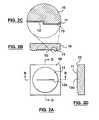
- FIG. 2Ais a plan view of a rotor according to a preferred embodiment of the present invention.
- FIG. 2Bis a cross-sectional view of the rotor along line B—B of FIG. 2A;
- FIG. 2Cis an enlarged view of a portion of the rotor of FIG. 2B;
- FIG. 2Dis a cross-sectional view of the rotor along line D—D of FIG. 2A;
- FIG. 3Ais a plan view of the rotor on the stator cluster in a valve closed position
- FIG. 3Bis a cross-sectional view of the rotor and stator cluster along line B—B of FIG. 3A;
- FIG. 4Ais a plan view of the rotor on the stator cluster in a valve open position
- FIG. 4Bis a cross-sectional view of the rotor and stator cluster along line B—B of FIG. 4A;
- FIG. 5Ais a plan view of a rotor according to a second embodiment of the present invention.
- FIG. 5Bis plan view of a stator cluster for a stator chip according to a second embodiment of the present invention.
- FIG. 5Cis a plan view of the rotor on the stator cluster of the second embodiment in a valve open position
- FIG. 5Dis a plan view of the rotor on the stator cluster of the second embodiment in a valve closed position
- FIG. 6Ais a plan view of a rotor according to a third embodiment of the present invention.
- FIG. 6Bis plan view of a stator cluster for a stator chip according to a third embodiment of the present invention.
- FIG. 6Cis a plan view of the rotor on the stator cluster of the third embodiment in a valve open position
- FIG. 6Dis a plan view of the rotor on the stator cluster of the third embodiment in a wash position
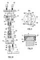
- FIG. 7is a perspective view of a rotary valve assembly according to a preferred embodiment of the present invention.
- FIG. 8is an exploded perspective view of the rotary valve assembly
- FIG. 9is a top plan view of the rotary valve assembly
- FIG. 10is an exploded cross-sectional view of the rotary valve assembly along line A—A of FIG. 9;
- FIG. 11is a cross-sectional view of the rotary valve assembly along line B—B of FIG. 9;
- FIG. 12is a cross-sectional view of the rotary valve assembly along line A—A of FIG. 9;
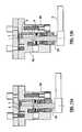
- FIG. 13Ais a cross-sectional view of a second embodiment of the rotary valve assembly in an assembled position
- FIG. 13Bis a cross-sectional view of the second embodiment in a partially disassembled position
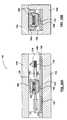
- FIG. 14Ais a cross-sectional view of a multi-valve rotary valve assembly according to an alternative embodiment of the present invention.
- FIG. 14Bis a plan view of a multi-valve stator chip according to an alternative embodiment of the present invention.
- FIGS. 15A and 15Bshow side views of a first embodiment of a translational variant of the valve of the present invention.
- FIGS. 16A and 16Bshow side and front view of a second embodiment of the translational variant of the present invention.
- a microfluidic deviceis a fluidic device that is either:
- a)is manufactured by micromachining (such as for example by using lithography, masks and photosensitive polymers to define features on a substrate and then using those features to etch or otherwise remove underlying layers or to build up additional layers) followed by bonding additional substrates to form closed channels;
- b)has typical smallest dimensions between 250 ⁇ m and 1 ⁇ m;
- c)has manufactured from a mold or master which itself meets either of the criteria set out in (a) or (b) above.
- microfluidic deviceis a channel chemically etched in glass. That is, chrome and gold films are put on the glass with a photosensitive polymer (photoresist) on top. A light source (UV or x-ray) and a photomask are used together to expose areas of the photosensitive polymer. The photoresist is developed, exposing the metal layer in some areas. The Au and Cr in the exposed areas are removed chemically, exposing the substrate beneath which can then be etched in a number of ways.
- photosensitive polymerphotoresist
- a light sourceUV or x-ray
- photomaskare used together to expose areas of the photosensitive polymer.
- the photoresistis developed, exposing the metal layer in some areas.
- the Au and Cr in the exposed areasare removed chemically, exposing the substrate beneath which can then be etched in a number of ways.
- a wet isotropic etchimmersion in HF (hydrofluoric acid) is used.
- the profile of the channelwill be roughly semicircular and will range in size from about 15 ⁇ m wide and 5 ⁇ m deep to 400 ⁇ m wide and 200 ⁇ m deep (the width is approximately 2 ⁇ the depth+the original width of the exposed line).
- Quartzcan be etched as above or can be etched using Deep Reactive Ion Etching which produces square, rather than 1 ⁇ 4 circular, sides (i.e. etches straight down).
- Siliconcan be etched using either of the methods above.
- chemical anisotropic etches for siliconwhich preferentially etch in specific crystallographic directions producing channels of other distinct geometries.
- Chipmeans one or more substrates which may be micromachined in accordance with conventional techniques.
- the preferred substrates for direct micromachiningare glass, silicon, or quartz.
- quartzis an especially attractive material for the basic reason that analytical chemists have long worked using fused silica capillaries and have experience in exploiting and manipulating the surface qualities of this media. Quartz and other glasses have very similar properties to fused silica and their use removes some obstacles to porting technologies into the microchip format.
- quartzis an extremely brittle material.
- the application of point forceseasily results in the propagation of cracks throughout the material.
- the first problemwas that the rotor would crack upon applying a force to press the rotor against the stator. This problem was overcome by placing one or two layers of tissue between the rotor and the shaft allowed a more even distribution of force from the shaft to the rotor and eliminated point forces caused by roughness of the stator cavity in the shaft
- Another problemwas cracking of the rotor due to rotor geometry caused by forces acting on the corners of the square rotor during rotation. These forces caused point-loading on the rotor substrate, leading to cracking.
- This problemwas solved by etching a circular dais on the surface of the rotor so that the contact surface of the rotor is a circular rather than rectangular.
- a third problemwas caused by minor but unavoidable perturbations of the axis of rotation of the shaft to the normal of the face of the stator resulted in the surfaces of the rotor and stator being non-parallel so that upon rotation of the rotor against the stator pressure between the surfaces was non-uniform. This lead to difficulty in creating a seal and often to cracking or grinding of the contact surfaces.
- This problemwas solved by the addition of a thick (in the range of approximately 1-2 mm), compressible but firm material (e.g. cork or high durometer (60 or 70) rubber) between the rotor and the shaft allows the rotor/substrate surfaces to remain parallel despite small variations in the axis of rotation of the shaft. This also provides the function of the tissue required to solve the first problem described above.
- FIGS. 1A-1Fshow a stator chip 2 for a microfluidic rotary valve according to a preferred embodiment of the present invention.
- An inlet for a test sample or the like and an outlet (described in detail below)are provided in the stator chip 2 .
- the stator chipis composed of a first planar substrate 20 acting as a bottom plate and a second planar substrate 21 acting as a cover plate.
- a first inlet channel 22 a and a first outlet channel 22 bare etched into the first substrate 20 using conventional micromachining techniques.
- a second inlet channel 24 a and second outlet channel 24 bare drilled through the second substrate 21 using ultrasonic or laser drilling techniques.
- interconnect holes 23 a and 23 bmay be drilled into the second substrate 21 in order to connect the first inlet channel 22 a and first outlet channel 22 b to other fluidic systems (not shown) with which the valve may be used.
- Alignment holes 25 a , 25 b , 25 c , and 25 dmay be drilled into the second substrate in order to fix the stator chip 2 within the valve housing (described in detail below).
- Grinding and polishing of the first and second substrate 20 , 21 surfacesmay be required after drilling to ensure that the surfaces are flat.
- the first substrate 20 and second substrate 21are then bonded together by first cleaning the surfaces to allow a contact bond and by subsequently annealing the bonded substrates at an elevated temperature (for example at 1100° C. for quartz).
- the bondingis such that the first inlet channel 22 a and first outlet channel 22 b etched into first substrate 20 are covered by the second substrate 21 to form closed channels.
- the first inlet channel 22 a and first outlet channel 22 bcommunicate with the second inlet channel 24 a and second outlet channel 24 b , respectively.
- the first inlet channel 22 a and second inlet channel 24 aform the inlet described above, while the first outlet channel 22 b and the second outlet channel 24 b form the outlet described above.
- a stator low friction material layer 26such as a diamond-like carbon (DLC) coating (best shown in FIG. 1D) is deposited on the second substrate 21 contact surface 29 which engages a rotor 1 , described below.
- the DLC coatinghas very low friction and is very hard, thus preventing wear between the stator chip 2 and rotor 1 .
- the stator chip 2is enclosed into the housing by fastening the housing top to the housing center with the chip in the recess of the housing center.
- the configurationis such that this operation fixes the position of the stator chip 2 without subjecting the stator chip 2 to any forces that would act to twist or to otherwise deform the stator chip 2 .
- Deformation of the stator chip 2would cause difficulties in creating a good seal between the rotor 1 and the stator chip 2 , between the fluidic interconnects and the interconnect vias and also lead easily to the destruction of the stator chip.
- the cap 57is fastened there is a gap between the stator chip and the housing top.
- Micromachining process and especially the thermal bonding of the stator chip substratesentails by necessity thermal cycling of the material, leading to internal stresses in the material and subsequent material deformation to reduce those stresses.
- Thin filmssuch as are used in micromaching techniques and such as the final DLC coating of the rotor and stator chip also contribute to intrinsic stress and deformation.
- processes which minimize the accumulation of stress in the materialare preferred.
- the present inventionpreferably employs processes that are carried out using low temperature techniques when possible (for example, low energy film application), and longer than usual heating and cooling stages when high temperatures are unavoidable (for example, thermal bonding)
- FIGS. 2A-Dshow the rotor 1 , which is preferably a rotor chip composed of a rotor substrate 10 .
- a circular raised dais 11is formed in the rotor substrate 10 by etching away the material surrounding the dais 11 .
- a radial rotor channel 12 ais etched into the dais 11 at the same time as the material 15 surrounding the dais 11 so that depth of the channel 12 a is similar to the height of the step between the surrounding material 15 and the dais 11 .
- a rotor low friction material layersuch as a DLC coating 13 (best shown in FIG. 2 D), is deposited on the rotor contact surface 16 for engaging the stator chip 2 .
- the DLC coatinghas a thickness between 1 and 10 microns and covers the entire surface of the rotor including the inside of rotor channel 12 a.
- FIGS. 3-4show the rotor 1 superimposed over the stator chip 2 in a 1:1 valve implementation according to a preferred embodiment of the present invention.
- the stator cluster portion 27is the area of the contact surface 29 of the stator chip 2 that comes into contact with a facing surface of the rotor.
- the stator cluster portion 27has a stator center 28 (shown in FIG. 1A) against which the rotor center must be held.
- the stator center 28is a geometric point defined by the valve design as the center of rotation of the rotor 1 on the stator chip 2 .
- FIGS. 3A and 3Bshow the rotor channel 12 a of the rotor 1 positioned relative to the stator chip 2 , such that fluid communication between the second inlet channel 24 a and the second outlet channel 24 b is prevented and the valve is closed.
- FIGS. 4A and 4Bshow a valve open position, where the rotor channel 12 a is aligned with the second inlet channel 24 a and the second outlet channel 24 b to provide a fluid pathway therebetween, permitting fluid to flow through the valve.
- FIGS. 5A-Dshow an alternative embodiment of a rotor and stator chip according of the present invention in a 1:5 selector valve implementation.
- a radial rotor channel 12 bextends from the center 30 of the rotor dais 11 .
- a first inlet channel 22 cextends from the edge of the stator chip 2 to the center 28 of the stator cluster 27 and communicates with the rotor channel 12 b via a second inlet channel 24 c (not shown) extending through the second substrate 21 at the center 28 of the stator cluster 27 .
- First outlet channels 22 d - 22 hare arranged around an arc inscribed by the outer end of the radial rotor channel 12 b .
- First outlet channels 22 d-h(in the first substrate 20 ) communicate with five corresponding second outlet channels 24 d-h (in the second substrate 21 ), which in turn communicate with the stator contact surface 29 .
- FIG. 5Cshows a superposition of the rotor 1 over the stator cluster 27 with their respective centers 30 and 28 vertically aligned and with the rotor channel 12 b of rotor 1 rotated with respect to stator cluster 27 to create a pathway from first inlet channel 22 c through the second inlet channel 24 c and second outlet channel 24 d to first outlet channel 22 d .
- a fluid pathwaycan be created in a similar fashion with any of the first outlet channels 22 e-h by rotating the rotor 1 .
- the rotor 1may be moved into a valve closed position by rotating the rotor channel 12 b to a position out of fluid communication with the second outlet channels 24 d-h . It will be understood by those skilled in the art that any number of outlet channels may be formed in the stator cluster 27 and that any number of channel configurations may be formed in the rotor 1 .
- FIGS. 6A-Eshow a second alternative embodiment of the rotor and stator combination according to the present invention.
- This embodimentis identical to that shown in FIGS. 5A-D, except for the addition of a wash assembly described in detail below.
- the rotor 1includes an additional wash channel 32 which is composed of a pair radially spaced apart arcuate portions 32 a and 32 c connected by a radial portion 32 b .
- FIG. 6Bshows the stator cluster 27 for this embodiment wherein a wash inlet 33 is composed of an additional first inlet channel 22 i (in the first substrate 20 ) and an additional second inlet channel 24 i (in the second substrate 21 ) located distances 31 a , 31 b respectively from the center 28 of the stator cluster 27 .
- FIG. 6Cshows the equivalent function to that of FIG. 5C, such that there is no fluid communication between the wash inlet 33 and wash channel 32 .
- FIG. 6Dshows wash channel 32 establishing a fluid pathway between the wash inlet 33 and all of the first outlet channels 22 d - 22 h , thereby permitting a wash fluid to be sent through all of the outlet channels.
- Channel 12 bis in a position where it does not establish a fluid pathway permitting sample flow, thereby preventing the sample flow. This embodiment is most useful for multiple uses of the stator chip.
- FIG. 7shows a microfluidic rotary valve assembly for engaging the rotor 1 and stator chip 2 , according to a preferred embodiment of the present invention.
- the stator chip 2is located within a stator cavity 53 of a housing body 52 .
- Preferably four pins 6are received within corresponding alignment holes 54 drilled in the housing body 52 .
- the exposed ends of pins 6locate within alignment holes 25 a-d (shown in FIG. 1A) of the stator chip 2 to ensure that the center of the stator cluster 27 is fixed in relation to the center of the rotor 1 .
- the depth of the stator cavity 53is slightly greater than the thickness of the stator chip 2 , so that a housing cap 57 may be tightly fastened by any suitable fasteners, such as screws 70 , without exerting any deforming force on the stator chip 2 .
- the housing cap 57is made from a transparent material, such as plexiglass to permit optical observation of the stator chip 2 .
- the housing body 52also includes at least two threaded holes 60 (four threaded holes 60 e-g are shown) which communicate with interconnect holes in the stator chip 2 , such as holes 23 a-b (shown in FIG. 1 A).
- Capillaries or tubing 84can be connected to the threaded holes using conventional flat-bottomed chromatographic fittings 82 .
- the stator chip 2may then be connected to various other fluidic components or systems via the tubing 84 . This then ensures that all loads on the stator chip are from one side, pressing the slate or chip against the housing cap 57 .
- the housing cap 57can then be provided with a smooth surface, to prevent any stern concentration on the stator chip 2 .
- a rotor cushion 7 and rotor 1are inserted into a rotor cavity 58 in the shaft 3 .
- the rotor cushion 7may be constructed from any suitable resilient material.
- the cushion 7is approximately 1 to 2 mm in thickness and is made from a compressible but firm material, such as cork or high durometer (60-70) rubber.
- the rotor 1is fixed in relation to the shaft 3 .
- the depth of the rotor cavity 58is slightly smaller than the combined thickness of the compressed rotor cushion 7 and the rotor 1 , such that the rotor 1 protrudes out of the rotor cavity 58 of the shaft 3 .
- a needle bearing 55is received in a corresponding bore 71 in the housing body 52 .
- a portion of the shaft 3is received within the needle bearing 55 , with the remaining portion of the shaft 3 protruding from the bore 71 .
- a high durometer o-ring 81is inserted over the shaft 3 above the needle bearing 55 . The o-ring 81 is compressed by the bearing 55 against the bore 71 and the shaft 3 so as to hold the shaft 3 in the center of the bore 71 .
- a housing base 59is secured to the housing body 52 by conventional fasteners, such as screws 73 , received in corresponding holes 74 , 75 in the housing base 59 and housing body 52 , respectively.
- a three-piece thrust bearingcomprising a bearing ring 76 and two washers 77 a and 77 b , is located in a base cavity 72 within the housing base 59 .
- a biasing meanssuch as a stack of disc springs 4 sit on the washer 77 b and engage the protruding portion of shaft 3 which is received in the base cavity 72 . The disc springs 4 urge the shaft 3 into the housing body 52 in order to press the stator chip 2 against the rotor 1 .
- the stator chip 2is pushed away from the bottom of the stator cavity 53 and against the housing cap 57 .
- the disc springs 4exert sufficient force on the shaft 3 to bring the rotor 1 into sealing engagement with the stator 2 .
- the force with which the rotor 1 is pressed against the stator 2is determined by the type, number, stacking arrangement and compression of the disc springs. Accordingly, additional washer(s) 82 may be used to increase the compression of a given number of disc springs, as is known in the art.
- the shaft 3 and rotor 1are rotated by an actuating means, such as a handle 5 , or alternatively by a motor (not shown) connected to the shaft 3 .
- a handle shaft 78is received in a bore 79 in the housing base 59 which communicates with the base cavity 72 .
- a distal end 80 of the handle shaft 78engages a handle cavity 87 of the shaft 3 in order to rotate the shaft 3 .
- the distal end 80is provided with a flat surface and in known manner, at screw 83 engages that flat surface, to secure the handle shaft 78 to the shaft 3 .
- the shaft 3rotates the dais 11 of the rotor 1 against the stator cluster 27 of the stator chip 2 to open and close the valve as described in detail above.
- a sealis provided between the dais 11 of the rotor the stator cluster 27 by forcing the rotor 1 against the stator chip 2 .
- the sealing forceis provided the disc springs 4 which act on the shaft 3 .
- the force on the shaft 3forces the stator chip 2 slightly away from the bottom of the stator cavity 53 and against an inner surface the housing cap 57 .
- the inner surface of the housing cap 57is smooth and parallel to the plane of the stator chip 2 in order to minimize any point forces on the stator which may cause cracking or prevent formation of a seal.
- the rotor cushion 7distributes any point forces acting on the rotor 1 which may be caused by roughness of the shaft cavity 58 . By providing a more even force distribution, the rotor cushion reduces the likelihood of cracking or breaking of the rotor 1 . In addition, the rotor cushion also reduces forces caused by small misalignments in the axis of rotation to the shaft 3 relative to a plane normal to the rotor 1 and the stator chip 2 . The preferably circular shape of the rotor dais 11 also assists with the reduction of point forces on the rotor 1 .
- the rotary valve according to the present inventionis capable of operating at pressures of as high as 1000 PSI, although it can also operate at lower pressures.
- the rotary valve according to the present inventionpermits easy removal and replacement of the stator chip 2 by unscrewing the screws 70 and removing the housing cap 57 to access the stator chip 2 .
- the easy replacement of the stator chip 2is advantageous for analytical chemistry applications, where a single use chip may be desirable to avoid contamination problems.
- microfluidic rotary valve and stator chip according to the present inventionprovides an advantage over macromachined rotary valves which are connected to other microfluidic devices via tubing.
- the stator chip according to the present inventionmay be constructed with various microfluidic devices (such as a sample injector, reaction chamber, mixer, etc.) integrated into the stator chip and connected to the stator cluster by channels.
- microfluidic devicessuch as a sample injector, reaction chamber, mixer, etc.
- such a chipwould be contained within the valve housing, as described above.
- a portion of the chipmay then be used as the stator cluster 27 (as described above) to control fluid flow to the remaining portions of the chip which carry out other microfluidic processes.
- Channels within the chip constructed as described abovewould provide fluid communication between the stator cluster 27 and the various microfluidic devices constructed on the stator chip 2 .
- Such an integrated chipcombines the advantages of microfluidics (such as faster reactions, reduced material costs, minimal dead and swept volumes) with the advantages of a rotary valve (such as high functionality, high pressure operation). Consequently, such an integrated stator chip avoids the disadvantages of plumbing from a microfluidic chip to a conventional rotary valve. These disadvantages include increased dead and swept volumes, and decreased performance.
- the further advantage of combining the number of devices, and possibly one or more valves in one chip,is that all the critical operations are then contained on a single chip. It is then not necessary to be concerned with details of connections to the chip. In other words, connections can be made to the chip with relatively large dead volumes, since critical operations requiring maintenance of small dead volumes are all contained on the chip.
- FIGS. 13A and 13Bshow an alternative embodiment of the rotary valve where force on the disc springs 4 is generated by tightening an externally threaded nut 80 which is received in a threaded bore 81 of the housing base 59 .
- the remaining parts of the valveare identical to the preferred embodiment described above, and their description is not repeated.
- the nut 80may partially unscrewed from the housing body 59 so that the rotor 1 no longer exerts pressure on the stator chip 2 .
- the stator chip 2can then be replaced as described above.
- the rotor 1can also be replaced by removing the nut 80 from the housing body, permitting the removal of the handle 5 and shaft 3 from the housing base 59 and body 52 .
- the rotor 1can then be removed from shaft cavity 58 and replaced by another rotor. Replacement of the rotor permits the use of different valving configurations for the valve. Otherwise the operation of the valve is identical to that described above.
- FIGS. 14A and 14Bshow yet another alternative embodiment of the rotary valve according to the present invention.
- a multi-valve stator chip 90includes two stator clusters 27 a and 27 b and is received in a modified housing body 92 and housing base 99 .
- the housing body and baseare modified to receive two identical shaft assemblies 94 a and 94 b which control two rotors (not shown).
- Each rotorcan operate independently to provide more flexibility in the valving configurations. Otherwise, the valve operates as described in detail above.
- valvesin which the rotor is replaced by a valve member that does not rotate, but instead is subject to translational movement or sliding movement along a line. It is also possible that the valves could be configured to have valve members that are subject to a combination of both translational and rotary motion.
- FIGS. 15A and 15Bshow a first embodiment of a translational variant of the valve of the present invention.
- the statoris indicated at 102 and includes a first substrate 104 and second substrate 106 , as in the earlier embodiments.
- This first embodimentincludes two inlets indicated at 112 , 114 . Details are provided only for inlet 112 , and it includes an interconnect hole 112 A, a first inlet channel 112 B and a second inlet channel 112 C.
- the first inlet channel 112 Bis formed by etching in the first substrate 104
- the second inlet channel 112 Cis formed, for example, by drilling, as a hole passing through the second substrate 106 .
- outlet 116there is provided an outlet indicated at 116 .
- the outletwould have a similar form to each of the inlets 112 , 114 , but is out of the plane of FIG. 15 A.
- valve member 108replacing the rotor of the earlier embodiments.
- the valve member 108includes a raised dais 110 , corresponding to that of the earlier embodiments.
- the raised dais 110includes a channel permitting fluid communication between an inlet and outlet pair as detailed below.
- the valve member 108is mounted in a valve holder 118 .
- a pressure mechanismis provided above the holder 118 .
- the pressure mechanismincludes a fixed bracket 120 , and a piston and cylinder assembly indicated at 122 , 124 .
- the piston 122is pivotally attached at one end to the bracket 120 and slidably mounted within the piston 122 .
- the piston 124is pivotally attached to the top, center of the holder 118 .
- a spring 126acts between the piston 122 and the cylinder 124 to maintain a downward force, F1, on the holder 118 .
- a screw nut mechanismis provided on one side comprising a fixed threaded member 130 and a screw 132 . An end of the screw 132 abuts the holder 118 .
- a second piston and cylinder arrangementcomprising a piston 136 slidably mounted in a cylinder 138 .
- the cylinder 138is fixed relative to the stator 102 and the fixed bracket 120 .
- a sprint 138acts between the cylinder 134 and the piston 136 , to press the piston 136 against the holder 118 .
- FIG. 15Ashows a neutral position of the valve member 108 , in which no fluid connection is made. If the screw member 132 is screwed in, then the valve member 108 with the holder 118 are displaced to the right, to the position in FIG. 15 B. Then, fluid connection is provided between the inlet 114 and the outlet 116 .
- FIGS. 16A and 16Bshow a second embodiment of this translational variation of the invention. This second embodiment is generally indicated by the reference 140 .
- a housingcomprises a housing base 142 and a housing cap 144 . These define an elongate channel, and at the bottom of the channel, there is located the stator, again comprising first and second substrates 146 , 148 .
- the statoragain comprising first and second substrates 146 , 148 .
- an inlet 150 and an outlet 152are provided. As shown, they have similar configurations as in preceding embodiments, and their details are not described again.
- a moving valve memberis shown at 154 , and again includes a raised dais 156 with a fluid channel (not shown).
- the moving valve member 154is mounted in a holder comprising a holder base 158 and holder cap 160 .
- a plurality of disc springs 162are provided between the valve member 154 and the holder cap 160 .
- various meanscould be provided to spread the load provided by the springs 162 , and to accommodate minor misalignments, tolerances and the like.
- bearings 180are provided between the valve holder 158 , 160 and the valve housing 142 , 144 . This constrains the valve member 154 to travel in the plane of FIG. 16 A.
- a screw mechanismcomprising a fixed threaded member 170 and a screw 172 is provided on one side, abutting the valve holder 160 .
- a piston and cylinder arrangementwith a piston 176 slidably mounted to a cylinder 174 is provided on the other side.
- a spring 178provides a biasing force F2, maintaining the valve holder 160 against the screw 172 .
- the screw 172can be used to move a channel in the valve member 154 , so that it either permits communication between the inlet and outlet 150 , 152 , or closes off the inlet 150 from the outlet 152 .
- a translational version of the invention in FIGS. 15, 16can also incorporate the variants mentioned for the rotational aspects of the invention.
- the substratecan again include microfluidic devices. More than one valve can be incorporated on a single stator. Additionally, it is possible for a single stator to include microfluidic devices, and mixed valve types, e.g. one rotational valve and one translational valve.
Landscapes
- Engineering & Computer Science (AREA)
- General Engineering & Computer Science (AREA)
- Mechanical Engineering (AREA)
- Chemical & Material Sciences (AREA)
- Dispersion Chemistry (AREA)
- Computer Hardware Design (AREA)
- Microelectronics & Electronic Packaging (AREA)
- Theoretical Computer Science (AREA)
- Physics & Mathematics (AREA)
- Fluid Mechanics (AREA)
- Multiple-Way Valves (AREA)
Abstract
Description
Claims (35)
Priority Applications (1)
| Application Number | Priority Date | Filing Date | Title |
|---|---|---|---|
| US10/025,989US6748975B2 (en) | 2001-12-26 | 2001-12-26 | Microfluidic valve and method of manufacturing same |
Applications Claiming Priority (1)
| Application Number | Priority Date | Filing Date | Title |
|---|---|---|---|
| US10/025,989US6748975B2 (en) | 2001-12-26 | 2001-12-26 | Microfluidic valve and method of manufacturing same |
Publications (2)
| Publication Number | Publication Date |
|---|---|
| US20030116206A1 US20030116206A1 (en) | 2003-06-26 |
| US6748975B2true US6748975B2 (en) | 2004-06-15 |
Family
ID=21829197
Family Applications (1)
| Application Number | Title | Priority Date | Filing Date |
|---|---|---|---|
| US10/025,989Expired - Fee RelatedUS6748975B2 (en) | 2001-12-26 | 2001-12-26 | Microfluidic valve and method of manufacturing same |
Country Status (1)
| Country | Link |
|---|---|
| US (1) | US6748975B2 (en) |
Cited By (54)
| Publication number | Priority date | Publication date | Assignee | Title |
|---|---|---|---|---|
| US20050000900A1 (en)* | 2001-04-06 | 2005-01-06 | Fluidigm Corporation | Microfluidic chromatography |
| US20060149127A1 (en)* | 2004-12-30 | 2006-07-06 | Seddiqui Fred R | Disposable multi-lumen catheter with reusable stylet |
| US20070015989A1 (en)* | 2005-07-01 | 2007-01-18 | Avantis Medical Systems, Inc. | Endoscope Image Recognition System and Method |
| US20070142711A1 (en)* | 2005-12-13 | 2007-06-21 | Lex Bayer | Detachable Imaging Device, Endoscope Having A Detachable Imaging Device, And Method of Configuring Such An Endoscope |
| US20070279486A1 (en)* | 2006-05-19 | 2007-12-06 | Avantis Medical Systems, Inc. | Device and method for reducing effects of video artifacts |
| US20070293720A1 (en)* | 2005-01-05 | 2007-12-20 | Avantis Medical Systems, Inc. | Endoscope assembly and method of viewing an area inside a cavity |
| US20080003585A1 (en)* | 2006-06-29 | 2008-01-03 | Bio-Rad Laboratories, Inc., A Corporation Of The State Of Delaware | Purification and amplification of nucleic acids in a microfluidic device |
| US20080021274A1 (en)* | 2005-01-05 | 2008-01-24 | Avantis Medical Systems, Inc. | Endoscopic medical device with locking mechanism and method |
| US20080026451A1 (en)* | 2006-06-15 | 2008-01-31 | Braman Jeffrey C | System for isolating biomolecules from a sample |
| US20080033450A1 (en)* | 2006-08-04 | 2008-02-07 | Lex Bayer | Surgical Port With Embedded Imaging Device |
| US7347455B1 (en)* | 2004-05-04 | 2008-03-25 | Weldon Taquino | Riser protector |
| US20080253686A1 (en)* | 2007-04-10 | 2008-10-16 | Avantis Medical Systems, Inc. | Method and Device for Examining or Imaging an Interior Surface of a Cavity |
| US7455971B2 (en) | 1998-06-24 | 2008-11-25 | Illumina, Inc. | Multiplex decoding of array sensors with microspheres |
| US20090148847A1 (en)* | 2006-03-15 | 2009-06-11 | Micronics, Inc. | Rapid magnetic flow assays |
| WO2009156103A1 (en) | 2008-06-26 | 2009-12-30 | INSTITUT FüR MIKROTECHNIK MAINZ GMBH | Micro-valve and sealing device for use in a microfluidic system, and method for the production thereof |
| US20090325276A1 (en)* | 2006-09-27 | 2009-12-31 | Micronics, Inc. | Integrated microfluidic assay devices and methods |
| DE102008002675A1 (en) | 2008-06-26 | 2009-12-31 | INSTITUT FüR MIKROTECHNIK MAINZ GMBH | Microvalve and sealing device for use in a microfluidic system and method of making same |
| US20100171055A1 (en)* | 2007-02-28 | 2010-07-08 | Micromass Uk Limited | Liquid-Chromatography Apparatus Having Diffusion-Bonded Titanium Components |
| DE102009005874A1 (en) | 2009-01-21 | 2010-07-22 | Thinxxs Microtechnology Ag | Valve, in particular for a component of microfluid technology |
| US20100276617A1 (en)* | 2008-02-14 | 2010-11-04 | Shimadzu Corporation | Flow channel switching valve |
| US20110006237A1 (en)* | 2009-07-13 | 2011-01-13 | Idex Health & Science Llc | Rotary shear valve assembly with hard-on-hard seal surfaces |
| US20110070654A1 (en)* | 2009-09-23 | 2011-03-24 | Ecolab Inc. | Valve analytical system |
| US8235887B2 (en) | 2006-01-23 | 2012-08-07 | Avantis Medical Systems, Inc. | Endoscope assembly with retroscope |
| US20120244534A1 (en)* | 2004-10-27 | 2012-09-27 | Cephied | Closed-system multi-stage nucleic acid amplification reactions |
| US8289381B2 (en) | 2005-01-05 | 2012-10-16 | Avantis Medical Systems, Inc. | Endoscope with an imaging catheter assembly and method of configuring an endoscope |
| US8287446B2 (en) | 2006-04-18 | 2012-10-16 | Avantis Medical Systems, Inc. | Vibratory device, endoscope having such a device, method for configuring an endoscope, and method of reducing looping of an endoscope |
| US20130206319A1 (en)* | 2011-08-10 | 2013-08-15 | Birgit Stadelbauer | Manufacturing method for microvalves |
| WO2012047684A3 (en)* | 2010-10-07 | 2014-04-03 | Cadence Fluidics Company, Llc | Fluidic processor and method of use |
| US20140174541A1 (en)* | 2012-12-21 | 2014-06-26 | Waters Technologies Corporation | Rotary shear valve and associated methods |
| US8797392B2 (en) | 2005-01-05 | 2014-08-05 | Avantis Medical Sytems, Inc. | Endoscope assembly with a polarizing filter |
| WO2014138203A2 (en) | 2013-03-05 | 2014-09-12 | Board Of Regents, The University Of Texas System | Microfluidic devices for the rapid and automated processing of sample populations |
| US8872906B2 (en) | 2005-01-05 | 2014-10-28 | Avantis Medical Systems, Inc. | Endoscope assembly with a polarizing filter |
| US8876081B2 (en) | 2009-07-13 | 2014-11-04 | Idex Health & Science Llc | Rotary shear valve assembly with a polymer insert device |
| WO2015191916A1 (en) | 2014-06-11 | 2015-12-17 | Micronics, Inc. | Microfluidic cartridges and apparatus with integrated assay controls for analysis of nucleic acids |
| US20160025690A1 (en)* | 2013-03-11 | 2016-01-28 | Shimadzu Corporation | Flow path switching valve |
| WO2016033455A1 (en) | 2014-08-29 | 2016-03-03 | The Arizona Board Of Regents On Behalf Of The University Of Arizona | Methods, devices, and systems for microfluidic stress emulation |
| US20170328872A1 (en)* | 2014-11-21 | 2017-11-16 | Waters Technologies Corporation | Chromatographic separation device having improved peak capacity |
| CN107407664A (en)* | 2015-03-30 | 2017-11-28 | 通用电气健康护理生物科学股份公司 | Rotary Valves and Chromatography Systems |
| US20180031528A1 (en)* | 2015-02-09 | 2018-02-01 | MAX-PLANCK-Gesellschaft zur Förderung der Wissenschaften e.V. | Means and methods for minimizing swept and dead volumes in chromatographic applications |
| US9895692B2 (en) | 2010-01-29 | 2018-02-20 | Micronics, Inc. | Sample-to-answer microfluidic cartridge |
| US10065186B2 (en) | 2012-12-21 | 2018-09-04 | Micronics, Inc. | Fluidic circuits and related manufacturing methods |
| US10087440B2 (en) | 2013-05-07 | 2018-10-02 | Micronics, Inc. | Device for preparation and analysis of nucleic acids |
| US10124335B2 (en) | 2016-07-13 | 2018-11-13 | Delta Electronics Int'l (Singapore) Pte Ltd | Integrated fluidic module |
| US10190153B2 (en) | 2013-05-07 | 2019-01-29 | Micronics, Inc. | Methods for preparation of nucleic acid-containing samples using clay minerals and alkaline solutions |
| US10307724B2 (en) | 2015-07-02 | 2019-06-04 | Centrillion Technology Holdings Corporation | Systems and methods to dispense and mix reagents |
| US10309545B2 (en) | 2016-07-13 | 2019-06-04 | Delta Electronics Int'l (Singapore) Pte Ltd | Fluid control device |
| US10376888B2 (en) | 2014-07-03 | 2019-08-13 | Centrillion Technology Holdings Corporation | Device for storage and dispensing of reagents |
| US10386377B2 (en) | 2013-05-07 | 2019-08-20 | Micronics, Inc. | Microfluidic devices and methods for performing serum separation and blood cross-matching |
| US10436713B2 (en) | 2012-12-21 | 2019-10-08 | Micronics, Inc. | Portable fluorescence detection system and microassay cartridge |
| US10518262B2 (en) | 2012-12-21 | 2019-12-31 | Perkinelmer Health Sciences, Inc. | Low elasticity films for microfluidic use |
| CN111135892A (en)* | 2020-02-21 | 2020-05-12 | 厦门大学 | Micro-fluidic chip control equipment, micro-fluidic control system and micro-fluidic chip |
| US11084031B1 (en) | 2019-02-19 | 2021-08-10 | Facebook Technologies, Llc | Methods of fabricating microfluidic valves and systems |
| US11198125B1 (en) | 2019-02-19 | 2021-12-14 | Facebook Technologies, Llc | Microfluidic valves, systems, and related methods |
| DE102023119806A1 (en) | 2023-07-26 | 2025-01-30 | Hochschule Aalen, Körperschaft des öffentlichen Rechts | Device for transferring a liquid sample within a microfluidic system |
Families Citing this family (22)
| Publication number | Priority date | Publication date | Assignee | Title |
|---|---|---|---|---|
| US7413709B2 (en)* | 2003-02-12 | 2008-08-19 | Agilent Technologies, Inc. | PAEK-based microfluidic device with integrated electrospray emitter |
| EP1520837B1 (en)* | 2004-05-22 | 2007-02-07 | Agilent Technologies, Inc. | Component part of a microfluidic valve |
| US7213547B2 (en)* | 2004-12-14 | 2007-05-08 | Massachusetts Institute Of Technology | Valve |
| US7462280B2 (en)* | 2005-07-22 | 2008-12-09 | Agilent Technologies, Inc. | Liquid chromatography chip with flexible interface |
| US7819948B2 (en)* | 2007-10-29 | 2010-10-26 | Air Products And Chemicals, Inc. | Rotary valve |
| WO2009111461A2 (en)* | 2008-03-04 | 2009-09-11 | University Of Utah Research Foundation | Microfluidic flow cell |
| US8622987B2 (en)* | 2008-06-04 | 2014-01-07 | The University Of Chicago | Chemistrode, a plug-based microfluidic device and method for stimulation and sampling with high temporal, spatial, and chemical resolution |
| US8110148B2 (en)* | 2008-11-06 | 2012-02-07 | Siemens Medical Solutions Usa, Inc. | Apparatus and method using rotary flow distribution mechanisms |
| DE102009027352A1 (en)* | 2009-06-30 | 2011-01-05 | Qiagen Gmbh | Micro valve seal |
| HU228053B1 (en) | 2009-11-18 | 2012-09-28 | Budapesti Mueszaki Es Gazdasagtudomanyi Egyetem | Valve for micro-fluidic channel |
| WO2012042226A2 (en)* | 2010-10-01 | 2012-04-05 | Oxford Nanopore Technologies Limited | Biochemical analysis apparatus and rotary valve |
| GB2492955A (en) | 2011-07-13 | 2013-01-23 | Oxford Nanopore Tech Ltd | One way valve |
| CN103930144A (en) | 2011-09-15 | 2014-07-16 | 牛津纳米孔技术有限公司 | Piston seal |
| DE102012005270A1 (en) | 2012-03-10 | 2013-09-12 | Microfluidic Chipshop Gmbh | Device for manipulating liquids |
| JP6630566B2 (en)* | 2012-07-05 | 2020-01-15 | メソ スケール テクノロジーズ エルエルシー | Analysis evaluation cartridge valve system |
| US10527192B2 (en)* | 2018-02-15 | 2020-01-07 | Talis Biomedical Corporation | Rotary valve |
| US20200064313A1 (en)* | 2018-08-21 | 2020-02-27 | Waters Technologies Corporation | Stator array for a multi-valve system |
| US11008627B2 (en) | 2019-08-15 | 2021-05-18 | Talis Biomedical Corporation | Diagnostic system |
| WO2021236928A1 (en)* | 2020-05-22 | 2021-11-25 | Waters Technologies Corporation | Multiple sample channel device for liquid chromatography |
| US11506641B2 (en) | 2021-01-26 | 2022-11-22 | Waters Technologies Corporation | Rotary valve having bypass state |
| WO2023087280A1 (en)* | 2021-11-19 | 2023-05-25 | 深圳华大生命科学研究院 | Microfluidic device and usage method therefor |
| CN115845941B (en)* | 2022-12-15 | 2025-09-16 | 南方科技大学 | Manufacturing method of microfluidic chip |
Citations (9)
| Publication number | Priority date | Publication date | Assignee | Title |
|---|---|---|---|---|
| US4242909A (en) | 1979-04-19 | 1981-01-06 | Rheodyne Incorporated | Sample injector |
| US4625569A (en) | 1984-01-17 | 1986-12-02 | Toyo Soda Manufacturing Co., Ltd. | Liquid injection device |
| US5400824A (en)* | 1991-01-21 | 1995-03-28 | Robert Bosch Gmbh | Microvalve |
| US5865417A (en) | 1996-09-27 | 1999-02-02 | Redwood Microsystems, Inc. | Integrated electrically operable normally closed valve |
| US6012488A (en) | 1998-09-17 | 2000-01-11 | Rheodyne, L.P. | Segmenting valve |
| US6155123A (en) | 1998-04-17 | 2000-12-05 | Rheodyne, L.P. | Multivalving sample injection system |
| US6267143B1 (en) | 1999-06-29 | 2001-07-31 | Upchurch Scientific, Inc. | Selection valve with ferrule cluster |
| EP1197693A2 (en) | 2000-10-11 | 2002-04-17 | Innovadyne Technologies, Inc. | Hybrid valve apparatus, system and method for fluid handling |
| US6585296B1 (en)* | 2000-10-23 | 2003-07-01 | Innovadyne Technologies, Inc. | Tube sealing assembly |
- 2001
- 2001-12-26USUS10/025,989patent/US6748975B2/ennot_activeExpired - Fee Related
Patent Citations (9)
| Publication number | Priority date | Publication date | Assignee | Title |
|---|---|---|---|---|
| US4242909A (en) | 1979-04-19 | 1981-01-06 | Rheodyne Incorporated | Sample injector |
| US4625569A (en) | 1984-01-17 | 1986-12-02 | Toyo Soda Manufacturing Co., Ltd. | Liquid injection device |
| US5400824A (en)* | 1991-01-21 | 1995-03-28 | Robert Bosch Gmbh | Microvalve |
| US5865417A (en) | 1996-09-27 | 1999-02-02 | Redwood Microsystems, Inc. | Integrated electrically operable normally closed valve |
| US6155123A (en) | 1998-04-17 | 2000-12-05 | Rheodyne, L.P. | Multivalving sample injection system |
| US6012488A (en) | 1998-09-17 | 2000-01-11 | Rheodyne, L.P. | Segmenting valve |
| US6267143B1 (en) | 1999-06-29 | 2001-07-31 | Upchurch Scientific, Inc. | Selection valve with ferrule cluster |
| EP1197693A2 (en) | 2000-10-11 | 2002-04-17 | Innovadyne Technologies, Inc. | Hybrid valve apparatus, system and method for fluid handling |
| US6585296B1 (en)* | 2000-10-23 | 2003-07-01 | Innovadyne Technologies, Inc. | Tube sealing assembly |
Non-Patent Citations (1)
| Title |
|---|
| Monolithic Microfabricated Valves and Pumps by Multilayer Soft Lithography, Marc A. Unger, Hou-Pu Chou, Todd Thorsen, Axel Scherer, and Stephen R. Quake, Department of Applied Physics, California Institute of Technolgoy, Science, vol. 288, Apr. 7, 2000. |
Cited By (98)
| Publication number | Priority date | Publication date | Assignee | Title |
|---|---|---|---|---|
| US9399795B2 (en) | 1998-06-24 | 2016-07-26 | Illumina, Inc. | Multiplex decoding of array sensors with microspheres |
| US8460865B2 (en) | 1998-06-24 | 2013-06-11 | Illumina, Inc. | Multiplex decoding of array sensors with microspheres |
| US7455971B2 (en) | 1998-06-24 | 2008-11-25 | Illumina, Inc. | Multiplex decoding of array sensors with microspheres |
| US7217367B2 (en)* | 2001-04-06 | 2007-05-15 | Fluidigm Corporation | Microfluidic chromatography |
| US20050000900A1 (en)* | 2001-04-06 | 2005-01-06 | Fluidigm Corporation | Microfluidic chromatography |
| US7347455B1 (en)* | 2004-05-04 | 2008-03-25 | Weldon Taquino | Riser protector |
| US20120244534A1 (en)* | 2004-10-27 | 2012-09-27 | Cephied | Closed-system multi-stage nucleic acid amplification reactions |
| US8728765B2 (en)* | 2004-10-27 | 2014-05-20 | Cepheid | Closed-system multi-stage nucleic acid amplification reactions |
| US20060149127A1 (en)* | 2004-12-30 | 2006-07-06 | Seddiqui Fred R | Disposable multi-lumen catheter with reusable stylet |
| US8289381B2 (en) | 2005-01-05 | 2012-10-16 | Avantis Medical Systems, Inc. | Endoscope with an imaging catheter assembly and method of configuring an endoscope |
| US20080021274A1 (en)* | 2005-01-05 | 2008-01-24 | Avantis Medical Systems, Inc. | Endoscopic medical device with locking mechanism and method |
| US8872906B2 (en) | 2005-01-05 | 2014-10-28 | Avantis Medical Systems, Inc. | Endoscope assembly with a polarizing filter |
| US20070293720A1 (en)* | 2005-01-05 | 2007-12-20 | Avantis Medical Systems, Inc. | Endoscope assembly and method of viewing an area inside a cavity |
| US8797392B2 (en) | 2005-01-05 | 2014-08-05 | Avantis Medical Sytems, Inc. | Endoscope assembly with a polarizing filter |
| US20070015989A1 (en)* | 2005-07-01 | 2007-01-18 | Avantis Medical Systems, Inc. | Endoscope Image Recognition System and Method |
| US20070142711A1 (en)* | 2005-12-13 | 2007-06-21 | Lex Bayer | Detachable Imaging Device, Endoscope Having A Detachable Imaging Device, And Method of Configuring Such An Endoscope |
| US8182422B2 (en) | 2005-12-13 | 2012-05-22 | Avantis Medical Systems, Inc. | Endoscope having detachable imaging device and method of using |
| US11529044B2 (en) | 2005-12-13 | 2022-12-20 | Psip Llc | Endoscope imaging device |
| US8235887B2 (en) | 2006-01-23 | 2012-08-07 | Avantis Medical Systems, Inc. | Endoscope assembly with retroscope |
| US10045685B2 (en) | 2006-01-23 | 2018-08-14 | Avantis Medical Systems, Inc. | Endoscope |
| US8772017B2 (en) | 2006-03-15 | 2014-07-08 | Micronics, Inc. | Integrated nucleic acid assays |
| US20090148847A1 (en)* | 2006-03-15 | 2009-06-11 | Micronics, Inc. | Rapid magnetic flow assays |
| US8222023B2 (en) | 2006-03-15 | 2012-07-17 | Micronics, Inc. | Integrated nucleic acid assays |
| US8287446B2 (en) | 2006-04-18 | 2012-10-16 | Avantis Medical Systems, Inc. | Vibratory device, endoscope having such a device, method for configuring an endoscope, and method of reducing looping of an endoscope |
| US8310530B2 (en) | 2006-05-19 | 2012-11-13 | Avantis Medical Systems, Inc. | Device and method for reducing effects of video artifacts |
| US8587645B2 (en) | 2006-05-19 | 2013-11-19 | Avantis Medical Systems, Inc. | Device and method for reducing effects of video artifacts |
| US20070279486A1 (en)* | 2006-05-19 | 2007-12-06 | Avantis Medical Systems, Inc. | Device and method for reducing effects of video artifacts |
| US8197399B2 (en) | 2006-05-19 | 2012-06-12 | Avantis Medical Systems, Inc. | System and method for producing and improving images |
| WO2007149791A3 (en)* | 2006-06-15 | 2008-11-27 | Stratagene Inc | System for isolating biomolecules from a sample |
| US20080026451A1 (en)* | 2006-06-15 | 2008-01-31 | Braman Jeffrey C | System for isolating biomolecules from a sample |
| US20080003585A1 (en)* | 2006-06-29 | 2008-01-03 | Bio-Rad Laboratories, Inc., A Corporation Of The State Of Delaware | Purification and amplification of nucleic acids in a microfluidic device |
| US20080033450A1 (en)* | 2006-08-04 | 2008-02-07 | Lex Bayer | Surgical Port With Embedded Imaging Device |
| US20110160535A1 (en)* | 2006-08-04 | 2011-06-30 | Avantis Medical Systems, Inc. | Surgical access port with embedded imaging device |
| US7927272B2 (en) | 2006-08-04 | 2011-04-19 | Avantis Medical Systems, Inc. | Surgical port with embedded imaging device |
| US20090325276A1 (en)* | 2006-09-27 | 2009-12-31 | Micronics, Inc. | Integrated microfluidic assay devices and methods |
| US20100171055A1 (en)* | 2007-02-28 | 2010-07-08 | Micromass Uk Limited | Liquid-Chromatography Apparatus Having Diffusion-Bonded Titanium Components |
| US10031113B2 (en)* | 2007-02-28 | 2018-07-24 | Waters Technologies Corporation | Liquid-chromatography apparatus having diffusion-bonded titanium components |
| US9044185B2 (en) | 2007-04-10 | 2015-06-02 | Avantis Medical Systems, Inc. | Method and device for examining or imaging an interior surface of a cavity |
| US20080253686A1 (en)* | 2007-04-10 | 2008-10-16 | Avantis Medical Systems, Inc. | Method and Device for Examining or Imaging an Interior Surface of a Cavity |
| US9613418B2 (en) | 2007-04-10 | 2017-04-04 | Avantis Medical Systems, Inc. | Method and device for examining or imaging an interior surface of a cavity |
| US8064666B2 (en) | 2007-04-10 | 2011-11-22 | Avantis Medical Systems, Inc. | Method and device for examining or imaging an interior surface of a cavity |
| US10354382B2 (en) | 2007-04-10 | 2019-07-16 | Avantis Medical Systems, Inc. | Method and device for examining or imaging an interior surface of a cavity |
| US20100276617A1 (en)* | 2008-02-14 | 2010-11-04 | Shimadzu Corporation | Flow channel switching valve |
| DE102008002675A1 (en) | 2008-06-26 | 2009-12-31 | INSTITUT FüR MIKROTECHNIK MAINZ GMBH | Microvalve and sealing device for use in a microfluidic system and method of making same |
| DE102008002675B4 (en)* | 2008-06-26 | 2014-11-06 | INSTITUT FüR MIKROTECHNIK MAINZ GMBH | Sealing device for use in a sample preparation chip and method for its production |
| US20110114869A1 (en)* | 2008-06-26 | 2011-05-19 | Institut Fur Mikrotechnik Mainz Gmbh | Micro-valve and sealing device for use in a microfluidic system, and method for the production thereof |
| WO2009156103A1 (en) | 2008-06-26 | 2009-12-30 | INSTITUT FüR MIKROTECHNIK MAINZ GMBH | Micro-valve and sealing device for use in a microfluidic system, and method for the production thereof |
| DE102008002674B9 (en)* | 2008-06-26 | 2010-10-21 | INSTITUT FüR MIKROTECHNIK MAINZ GMBH | Microvalve and sealing device for use in a microfluidic system and method of making same |
| US9322490B2 (en)* | 2008-06-26 | 2016-04-26 | Fraunhofer-Gesellschaft zur Förderung der angewandten Forschung e. V. | Micro-valve and sealing device for use in a microfluidic system, and method for the production thereof |
| US8911688B2 (en) | 2008-06-26 | 2014-12-16 | Fraunhofer-Gesellschaft zur Förderung der angewandten Forschung e.V. | Microvalve and sealing device for use in a microfluidics system, and method for the production thereof |
| US20110104024A1 (en)* | 2008-06-26 | 2011-05-05 | Institut Fur Mikrotechnik Mainz Gmbh | Microvalve and sealing device for use in a microfluidics system, and method for the production thereof |
| DE102008002674B3 (en)* | 2008-06-26 | 2010-05-12 | INSTITUT FüR MIKROTECHNIK MAINZ GMBH | Microvalve and sealing device for use in a microfluidic system and method of making same |
| DE102009005874A1 (en) | 2009-01-21 | 2010-07-22 | Thinxxs Microtechnology Ag | Valve, in particular for a component of microfluid technology |
| WO2010083795A1 (en) | 2009-01-21 | 2010-07-29 | Thinxxs Microtechnology Ag | Valve, in particular for a component in microfluid technology |
| US8960230B2 (en) | 2009-01-21 | 2015-02-24 | Thinxxs Microtechnology Ag | Valve, in particular for a component in microfluid technology |
| US8905075B2 (en)* | 2009-07-13 | 2014-12-09 | Idex Health & Science Llc | Rotary shear valve assembly with hard-on-hard seal surfaces |
| US8876081B2 (en) | 2009-07-13 | 2014-11-04 | Idex Health & Science Llc | Rotary shear valve assembly with a polymer insert device |
| US20110006237A1 (en)* | 2009-07-13 | 2011-01-13 | Idex Health & Science Llc | Rotary shear valve assembly with hard-on-hard seal surfaces |
| US9388908B2 (en) | 2009-07-13 | 2016-07-12 | Idex Health & Science Llc | Rotary shear valve assembly with hard-on-hard seal surfaces |
| US20110070654A1 (en)* | 2009-09-23 | 2011-03-24 | Ecolab Inc. | Valve analytical system |
| US8178352B2 (en) | 2009-09-23 | 2012-05-15 | Ecolab Usa Inc. | Valve analytical system |
| US8008080B2 (en) | 2009-09-23 | 2011-08-30 | Ecolab Usa Inc. | Valve analytical system |
| WO2011036622A3 (en)* | 2009-09-23 | 2011-08-04 | Ecolab Usa Inc. | Lab-on-valve analytical system |
| US9895692B2 (en) | 2010-01-29 | 2018-02-20 | Micronics, Inc. | Sample-to-answer microfluidic cartridge |
| US9027929B2 (en) | 2010-10-07 | 2015-05-12 | Neil R. Picha | Fluidic processor and method of use |
| WO2012047684A3 (en)* | 2010-10-07 | 2014-04-03 | Cadence Fluidics Company, Llc | Fluidic processor and method of use |
| US20130206319A1 (en)* | 2011-08-10 | 2013-08-15 | Birgit Stadelbauer | Manufacturing method for microvalves |
| US8740045B2 (en)* | 2011-08-10 | 2014-06-03 | Buerkert Werke Gmbh | Manufacturing method for microvalves |
| US10065186B2 (en) | 2012-12-21 | 2018-09-04 | Micronics, Inc. | Fluidic circuits and related manufacturing methods |
| US9303775B2 (en)* | 2012-12-21 | 2016-04-05 | Waters Technologies Corporation | Rotary shear valve and associated methods |
| US11181105B2 (en) | 2012-12-21 | 2021-11-23 | Perkinelmer Health Sciences, Inc. | Low elasticity films for microfluidic use |
| US10518262B2 (en) | 2012-12-21 | 2019-12-31 | Perkinelmer Health Sciences, Inc. | Low elasticity films for microfluidic use |
| US10436713B2 (en) | 2012-12-21 | 2019-10-08 | Micronics, Inc. | Portable fluorescence detection system and microassay cartridge |
| US20140174541A1 (en)* | 2012-12-21 | 2014-06-26 | Waters Technologies Corporation | Rotary shear valve and associated methods |
| US11192109B2 (en) | 2013-03-05 | 2021-12-07 | Board Of Regents, The University Of Texas System | Microfluidic devices for the rapid and automated processing of sample populations |
| WO2014138203A2 (en) | 2013-03-05 | 2014-09-12 | Board Of Regents, The University Of Texas System | Microfluidic devices for the rapid and automated processing of sample populations |
| US10052631B2 (en) | 2013-03-05 | 2018-08-21 | Board Of Regents, The University Of Texas System | Microfluidic devices for the rapid and automated processing of sample populations |
| US20160025690A1 (en)* | 2013-03-11 | 2016-01-28 | Shimadzu Corporation | Flow path switching valve |
| US10386377B2 (en) | 2013-05-07 | 2019-08-20 | Micronics, Inc. | Microfluidic devices and methods for performing serum separation and blood cross-matching |
| US10190153B2 (en) | 2013-05-07 | 2019-01-29 | Micronics, Inc. | Methods for preparation of nucleic acid-containing samples using clay minerals and alkaline solutions |
| US10087440B2 (en) | 2013-05-07 | 2018-10-02 | Micronics, Inc. | Device for preparation and analysis of nucleic acids |
| US11016108B2 (en) | 2013-05-07 | 2021-05-25 | Perkinelmer Health Sciences, Inc. | Microfluidic devices and methods for performing serum separation and blood cross-matching |
| WO2015191916A1 (en) | 2014-06-11 | 2015-12-17 | Micronics, Inc. | Microfluidic cartridges and apparatus with integrated assay controls for analysis of nucleic acids |
| US10376888B2 (en) | 2014-07-03 | 2019-08-13 | Centrillion Technology Holdings Corporation | Device for storage and dispensing of reagents |
| WO2016033455A1 (en) | 2014-08-29 | 2016-03-03 | The Arizona Board Of Regents On Behalf Of The University Of Arizona | Methods, devices, and systems for microfluidic stress emulation |
| US20170328872A1 (en)* | 2014-11-21 | 2017-11-16 | Waters Technologies Corporation | Chromatographic separation device having improved peak capacity |
| US20180031528A1 (en)* | 2015-02-09 | 2018-02-01 | MAX-PLANCK-Gesellschaft zur Förderung der Wissenschaften e.V. | Means and methods for minimizing swept and dead volumes in chromatographic applications |
| CN107407664A (en)* | 2015-03-30 | 2017-11-28 | 通用电气健康护理生物科学股份公司 | Rotary Valves and Chromatography Systems |
| US10307724B2 (en) | 2015-07-02 | 2019-06-04 | Centrillion Technology Holdings Corporation | Systems and methods to dispense and mix reagents |
| US10309545B2 (en) | 2016-07-13 | 2019-06-04 | Delta Electronics Int'l (Singapore) Pte Ltd | Fluid control device |
| US10124335B2 (en) | 2016-07-13 | 2018-11-13 | Delta Electronics Int'l (Singapore) Pte Ltd | Integrated fluidic module |
| US11084031B1 (en) | 2019-02-19 | 2021-08-10 | Facebook Technologies, Llc | Methods of fabricating microfluidic valves and systems |
| US11198125B1 (en) | 2019-02-19 | 2021-12-14 | Facebook Technologies, Llc | Microfluidic valves, systems, and related methods |
| US11590492B1 (en) | 2019-02-19 | 2023-02-28 | Meta Platforms Technologies, Llc | Methods of fabricating microfluidic valves and systems |
| CN111135892B (en)* | 2020-02-21 | 2021-01-05 | 厦门大学 | Micro-fluidic chip control equipment, micro-fluidic control system and micro-fluidic chip |
| CN111135892A (en)* | 2020-02-21 | 2020-05-12 | 厦门大学 | Micro-fluidic chip control equipment, micro-fluidic control system and micro-fluidic chip |
| DE102023119806A1 (en) | 2023-07-26 | 2025-01-30 | Hochschule Aalen, Körperschaft des öffentlichen Rechts | Device for transferring a liquid sample within a microfluidic system |
| WO2025021866A1 (en) | 2023-07-26 | 2025-01-30 | Hochschule Aalen, Koerperschaft Des Oeffentlichen Rechts | Device for transferring a liquid sample within a microfluidic system |
Also Published As
| Publication number | Publication date |
|---|---|
| US20030116206A1 (en) | 2003-06-26 |
Similar Documents
| Publication | Publication Date | Title |
|---|---|---|
| US6748975B2 (en) | Microfluidic valve and method of manufacturing same | |
| US7862000B2 (en) | Microfluidic method and structure with an elastomeric gas-permeable gasket | |
| EP1155254B1 (en) | Microfluidic connector | |
| US8961906B2 (en) | Fluid connector devices and methods of making and using the same | |
| US5653259A (en) | Valve block | |
| US20070286773A1 (en) | Microfluidic Device | |
| US7025324B1 (en) | Gating apparatus and method of manufacture | |
| EP1997772A2 (en) | Method of fabrication of a microfluidic device | |
| US6715733B2 (en) | High temperature micro-machined valve | |
| CN102812276B (en) | Microvalve | |
| US6056269A (en) | Microminiature valve having silicon diaphragm | |
| CA2690617C (en) | Diaphragm-sealed valve having intermediate communication ports | |
| US20030197139A1 (en) | Valve for use in microfluidic structures | |
| TWI306490B (en) | Apparatus for driving microfluid driving the method thereof | |
| JP4791491B2 (en) | Valve assembly with improved pump-down performance | |
| US6729350B2 (en) | Valve for use with capillary tubing | |
| US20020100714A1 (en) | Microfluidic devices | |
| CN1238029A (en) | Integrated electrically operable micro-valve | |
| US20070051412A1 (en) | Method and apparatus for the mechanical actuation of valves in fluidic devices | |
| CN1271064A (en) | Mixing valve | |
| JP2006276021A (en) | Apparatus, system and method for liquid chromatography | |
| EP1981636A1 (en) | A microfluidic method and structure with an elastomeric gas-permeable gasket | |
| JPH09505130A (en) | Micromachined valve device | |
| KR101347373B1 (en) | Microfluidic device havimg valve, and fabricating mehtod thereof | |
| JP2015507159A (en) | Diaphragm sealing valve with improved actuator structure |
Legal Events
| Date | Code | Title | Description |
|---|---|---|---|
| AS | Assignment | Owner name:MIICRALYNE INC., ALBERTA Free format text:ASSIGNMENT OF ASSIGNORS INTEREST;ASSIGNORS:HARTSHORNE, HERBERT A.;MCKINNON, GRAHAM H.;YU, PENGGUANG;AND OTHERS;REEL/FRAME:012738/0240;SIGNING DATES FROM 20020313 TO 20020320 Owner name:MDS INC, DOING BUSINESS AS MDS SCIEX, ONTARIO Free format text:ASSIGNMENT OF ASSIGNORS INTEREST;ASSIGNORS:HARTSHORNE, HERBERT A.;MCKINNON, GRAHAM H.;YU, PENGGUANG;AND OTHERS;REEL/FRAME:012738/0240;SIGNING DATES FROM 20020313 TO 20020320 Owner name:MDS PROTEOMICS INC., ONTARIO Free format text:ASSIGNMENT OF ASSIGNORS INTEREST;ASSIGNORS:HARTSHORNE, HERBERT A.;MCKINNON, GRAHAM H.;YU, PENGGUANG;AND OTHERS;REEL/FRAME:012738/0240;SIGNING DATES FROM 20020313 TO 20020320 | |
| AS | Assignment | Owner name:MDS INC., DOING BUSINESS AS MDS SCIEX, ONTARIO Free format text:ASSIGNMENT OF ASSIGNORS INTEREST;ASSIGNORS:HARTSHORNE, HERBERT A.;MCKINNON, GRAHAM H.;YU, PENGGUANG;AND OTHERS;REEL/FRAME:013078/0330 Effective date:20020313 Owner name:MDS PROTEOMICS INC., ONTARIO Free format text:ASSIGNMENT OF ASSIGNORS INTEREST;ASSIGNORS:HARTSHORNE, HERBERT A.;MCKINNON, GRAHAM H.;YU, PENGGUANG;AND OTHERS;REEL/FRAME:013078/0330 Effective date:20020313 Owner name:MICRALYNE INC., CANADA Free format text:ASSIGNMENT OF ASSIGNORS INTEREST;ASSIGNORS:HARTSHORNE, HERBERT A.;MCKINNON, GRAHAM H.;YU, PENGGUANG;AND OTHERS;REEL/FRAME:013078/0330 Effective date:20020313 | |
| AS | Assignment | Owner name:5131 INVESTMENTS LTD., CANADA Free format text:ASSIGNMENT OF ASSIGNORS INTEREST;ASSIGNOR:MDS PROTEOMICS INC.;REEL/FRAME:013323/0905 Effective date:20030103 Owner name:MDS PROTEOMICS INC., CANADA Free format text:CHANGE OF NAME;ASSIGNOR:5131 INVESTMENTS LTD.;REEL/FRAME:013323/0669 Effective date:20020822 | |
| AS | Assignment | Owner name:MICRAYLNE INC., CANADA Free format text:ASSIGNMENT OF ASSIGNORS INTEREST;ASSIGNORS:MDS PROTEOMICS INC.;MDS INC. (OPERATING AS MDS SCIEX);REEL/FRAME:016127/0621 Effective date:20040610 | |
| REMI | Maintenance fee reminder mailed | ||
| LAPS | Lapse for failure to pay maintenance fees | ||
| STCH | Information on status: patent discontinuation | Free format text:PATENT EXPIRED DUE TO NONPAYMENT OF MAINTENANCE FEES UNDER 37 CFR 1.362 | |
| FP | Lapsed due to failure to pay maintenance fee | Effective date:20080615 |