US6746885B2 - Method for making a semiconductor light source - Google Patents
Method for making a semiconductor light sourceDownload PDFInfo
- Publication number
- US6746885B2 US6746885B2US09/938,875US93887501AUS6746885B2US 6746885 B2US6746885 B2US 6746885B2US 93887501 AUS93887501 AUS 93887501AUS 6746885 B2US6746885 B2US 6746885B2
- Authority
- US
- United States
- Prior art keywords
- light
- heat sink
- enclosure
- semiconductor
- obtaining
- Prior art date
- Legal status (The legal status is an assumption and is not a legal conclusion. Google has not performed a legal analysis and makes no representation as to the accuracy of the status listed.)
- Expired - Lifetime, expires
Links
Images


Classifications
- F—MECHANICAL ENGINEERING; LIGHTING; HEATING; WEAPONS; BLASTING
- F21—LIGHTING
- F21K—NON-ELECTRIC LIGHT SOURCES USING LUMINESCENCE; LIGHT SOURCES USING ELECTROCHEMILUMINESCENCE; LIGHT SOURCES USING CHARGES OF COMBUSTIBLE MATERIAL; LIGHT SOURCES USING SEMICONDUCTOR DEVICES AS LIGHT-GENERATING ELEMENTS; LIGHT SOURCES NOT OTHERWISE PROVIDED FOR
- F21K9/00—Light sources using semiconductor devices as light-generating elements, e.g. using light-emitting diodes [LED] or lasers
- F21K9/20—Light sources comprising attachment means
- F21K9/23—Retrofit light sources for lighting devices with a single fitting for each light source, e.g. for substitution of incandescent lamps with bayonet or threaded fittings
- F21K9/232—Retrofit light sources for lighting devices with a single fitting for each light source, e.g. for substitution of incandescent lamps with bayonet or threaded fittings specially adapted for generating an essentially omnidirectional light distribution, e.g. with a glass bulb
- F—MECHANICAL ENGINEERING; LIGHTING; HEATING; WEAPONS; BLASTING
- F21—LIGHTING
- F21V—FUNCTIONAL FEATURES OR DETAILS OF LIGHTING DEVICES OR SYSTEMS THEREOF; STRUCTURAL COMBINATIONS OF LIGHTING DEVICES WITH OTHER ARTICLES, NOT OTHERWISE PROVIDED FOR
- F21V3/00—Globes; Bowls; Cover glasses
- F—MECHANICAL ENGINEERING; LIGHTING; HEATING; WEAPONS; BLASTING
- F21—LIGHTING
- F21K—NON-ELECTRIC LIGHT SOURCES USING LUMINESCENCE; LIGHT SOURCES USING ELECTROCHEMILUMINESCENCE; LIGHT SOURCES USING CHARGES OF COMBUSTIBLE MATERIAL; LIGHT SOURCES USING SEMICONDUCTOR DEVICES AS LIGHT-GENERATING ELEMENTS; LIGHT SOURCES NOT OTHERWISE PROVIDED FOR
- F21K9/00—Light sources using semiconductor devices as light-generating elements, e.g. using light-emitting diodes [LED] or lasers
- F21K9/60—Optical arrangements integrated in the light source, e.g. for improving the colour rendering index or the light extraction
- F21K9/64—Optical arrangements integrated in the light source, e.g. for improving the colour rendering index or the light extraction using wavelength conversion means distinct or spaced from the light-generating element, e.g. a remote phosphor layer
- F—MECHANICAL ENGINEERING; LIGHTING; HEATING; WEAPONS; BLASTING
- F21—LIGHTING
- F21V—FUNCTIONAL FEATURES OR DETAILS OF LIGHTING DEVICES OR SYSTEMS THEREOF; STRUCTURAL COMBINATIONS OF LIGHTING DEVICES WITH OTHER ARTICLES, NOT OTHERWISE PROVIDED FOR
- F21V29/00—Protecting lighting devices from thermal damage; Cooling or heating arrangements specially adapted for lighting devices or systems
- F21V29/50—Cooling arrangements
- F21V29/60—Cooling arrangements characterised by the use of a forced flow of gas, e.g. air
- F21V29/67—Cooling arrangements characterised by the use of a forced flow of gas, e.g. air characterised by the arrangement of fans
- F—MECHANICAL ENGINEERING; LIGHTING; HEATING; WEAPONS; BLASTING
- F21—LIGHTING
- F21V—FUNCTIONAL FEATURES OR DETAILS OF LIGHTING DEVICES OR SYSTEMS THEREOF; STRUCTURAL COMBINATIONS OF LIGHTING DEVICES WITH OTHER ARTICLES, NOT OTHERWISE PROVIDED FOR
- F21V29/00—Protecting lighting devices from thermal damage; Cooling or heating arrangements specially adapted for lighting devices or systems
- F21V29/50—Cooling arrangements
- F21V29/70—Cooling arrangements characterised by passive heat-dissipating elements, e.g. heat-sinks
- F—MECHANICAL ENGINEERING; LIGHTING; HEATING; WEAPONS; BLASTING
- F21—LIGHTING
- F21Y—INDEXING SCHEME ASSOCIATED WITH SUBCLASSES F21K, F21L, F21S and F21V, RELATING TO THE FORM OR THE KIND OF THE LIGHT SOURCES OR OF THE COLOUR OF THE LIGHT EMITTED
- F21Y2107/00—Light sources with three-dimensionally disposed light-generating elements
- F21Y2107/40—Light sources with three-dimensionally disposed light-generating elements on the sides of polyhedrons, e.g. cubes or pyramids
- F—MECHANICAL ENGINEERING; LIGHTING; HEATING; WEAPONS; BLASTING
- F21—LIGHTING
- F21Y—INDEXING SCHEME ASSOCIATED WITH SUBCLASSES F21K, F21L, F21S and F21V, RELATING TO THE FORM OR THE KIND OF THE LIGHT SOURCES OR OF THE COLOUR OF THE LIGHT EMITTED
- F21Y2115/00—Light-generating elements of semiconductor light sources
- F21Y2115/10—Light-emitting diodes [LED]
- H—ELECTRICITY
- H01—ELECTRIC ELEMENTS
- H01L—SEMICONDUCTOR DEVICES NOT COVERED BY CLASS H10
- H01L2224/00—Indexing scheme for arrangements for connecting or disconnecting semiconductor or solid-state bodies and methods related thereto as covered by H01L24/00
- H01L2224/01—Means for bonding being attached to, or being formed on, the surface to be connected, e.g. chip-to-package, die-attach, "first-level" interconnects; Manufacturing methods related thereto
- H01L2224/42—Wire connectors; Manufacturing methods related thereto
- H01L2224/47—Structure, shape, material or disposition of the wire connectors after the connecting process
- H01L2224/48—Structure, shape, material or disposition of the wire connectors after the connecting process of an individual wire connector
- H01L2224/4805—Shape
- H01L2224/4809—Loop shape
- H01L2224/48091—Arched
- H—ELECTRICITY
- H01—ELECTRIC ELEMENTS
- H01L—SEMICONDUCTOR DEVICES NOT COVERED BY CLASS H10
- H01L2224/00—Indexing scheme for arrangements for connecting or disconnecting semiconductor or solid-state bodies and methods related thereto as covered by H01L24/00
- H01L2224/01—Means for bonding being attached to, or being formed on, the surface to be connected, e.g. chip-to-package, die-attach, "first-level" interconnects; Manufacturing methods related thereto
- H01L2224/42—Wire connectors; Manufacturing methods related thereto
- H01L2224/47—Structure, shape, material or disposition of the wire connectors after the connecting process
- H01L2224/48—Structure, shape, material or disposition of the wire connectors after the connecting process of an individual wire connector
- H01L2224/484—Connecting portions
- H01L2224/48463—Connecting portions the connecting portion on the bonding area of the semiconductor or solid-state body being a ball bond
- H01L2224/48465—Connecting portions the connecting portion on the bonding area of the semiconductor or solid-state body being a ball bond the other connecting portion not on the bonding area being a wedge bond, i.e. ball-to-wedge, regular stitch
- H—ELECTRICITY
- H01—ELECTRIC ELEMENTS
- H01L—SEMICONDUCTOR DEVICES NOT COVERED BY CLASS H10
- H01L25/00—Assemblies consisting of a plurality of semiconductor or other solid state devices
- H01L25/03—Assemblies consisting of a plurality of semiconductor or other solid state devices all the devices being of a type provided for in a single subclass of subclasses H10B, H10D, H10F, H10H, H10K or H10N, e.g. assemblies of rectifier diodes
- H01L25/04—Assemblies consisting of a plurality of semiconductor or other solid state devices all the devices being of a type provided for in a single subclass of subclasses H10B, H10D, H10F, H10H, H10K or H10N, e.g. assemblies of rectifier diodes the devices not having separate containers
- H01L25/075—Assemblies consisting of a plurality of semiconductor or other solid state devices all the devices being of a type provided for in a single subclass of subclasses H10B, H10D, H10F, H10H, H10K or H10N, e.g. assemblies of rectifier diodes the devices not having separate containers the devices being of a type provided for in group H10H20/00
- H01L25/0753—Assemblies consisting of a plurality of semiconductor or other solid state devices all the devices being of a type provided for in a single subclass of subclasses H10B, H10D, H10F, H10H, H10K or H10N, e.g. assemblies of rectifier diodes the devices not having separate containers the devices being of a type provided for in group H10H20/00 the devices being arranged next to each other
Definitions
- the inventionrelates to the field of light sources and illumination devices. More particularly, the invention relates to semiconductor light sources and illumination devices useful for providing visible light in order to partially or fully illuminate a space occupied by or viewed by humans, such as residential space, commercial space, outdoor space, the interior or exterior of a vehicle, etc.
- LEDslight emitting diodes
- LEDsare desirable because they are a high efficiency light source that uses substantially less energy and creates less heat than typical prior art light sources such as incandescent and halogen lights.
- Prior art semiconductor light sourceshave not been successfully and economically used to illuminate physical spaces.
- LED'swere typically individually packaged in a module, either with or without a focus dome on the module. Typical prior art LED modules lack high light intensity due to the size of the LED chips used.
- U.S. Pat. No. 5,941,626discloses a long light emitting apparatus that uses a plurality of LED lamps (modules) connected in series.
- the LED modulesare spaced apart and appear to be intended for decorative use, such as on street lamp poles and on Christmas trees.
- U.S. Pat. No. 5,160,200discloses a wedge-base LED bulb housing.
- the patentdepicts a plurality of separate LED modules electrically connected to a wedge base.
- U.S. Pat. No. 4,675,575discloses light-emitting diode assemblies such as a mono-color or bi-color light string system. Each LED is in an envelope with light conducting optical spheres for light transmission and dispersion. The LED string system appears adapted for decorative use, such as for lighting Christmas trees.
- FIG. 1depicts a semiconductor light source of one embodiment of the invention using a high power chip or array arrangement.
- FIG. 2depicts a semiconductor light source of one embodiment of the invention using high power surface mount LED chip modules or lamps.
- FIG. 3 adepicts a LED with an insulating substrate.
- FIG. 3 bdepicts a detailed view of a LED structure on a sapphire substrate.
- FIG. 3 cdepicts a LED with a conducting substrate.
- FIG. 3 ddepicts a detailed view of a LED structure on a sapphire substrate.
- FIG. 3 edepicts a VCSEL chip on an insulating substrate.
- FIG. 3 fdepicts a detailed view of a VCSEL chip on a insulative substrate.
- FIG. 3 gdepicts a VCSEL chip on a conductive substrate.
- FIG. 3 hdepicts a detailed view of a VCSEL chip in a conductive substrate.
- FIG. 4 adepicts a top view of a LED array on a single chip with an insulating substrate.
- FIG. 4 bdepicts a top view of a LED array on a single chip with a conductive substrate.
- FIG. 4 cdepicts a top view of a VCSEL array on a single chip with an insulating substrate.
- FIG. 4 ddepicts a top view of a VCSEL array on a single chip with a conductive substrate.
- FIG. 5 adepicts a semiconductor chip of the invention that emits single color light using a conversion layer.
- FIG. 5 bdepicts a semiconductor chip of the invention that emits single color light using a phosphor coating.
- FIG. 6depicts a cross sectional view of a heat sink of the invention using a fan and TE cooler to circulate air and remove heat.
- FIG. 7 adepicts a single chip or single array chip package.
- FIG. 7 bdepicts a multiple chip package.
- FIG. 8 adepicts a chip package with phosphor covering on the semiconductor.
- FIG. 8 bdepicts a chip package with a uniform phosphor coating.
- FIG. 9depicts a high power LED package.
- FIG. 10depicts a LED or laser light source located in a light enclosure having a phosphor coating.
- FIG. 11depicts a power supply module with fitting for a light source of the invention.
- the light source 100includes a traditional bulb-shaped enclosure 101 .
- the enclosure 101may be of any desired shape, including spherical, cylindrical, elliptical, domed, square, n-sided where n is an integer, or otherwise.
- the enclosuremay be made from any desired light transparent or translucent materials, including glass, plastic, polycarbonate, and other light transparent materials.
- the enclosure 101has an exterior surface 101 a and an interior surface 101 b .
- the exterior surface 101 amay be smooth and glossy, matte, or another finish or texture.
- the exterior surface 101 amay be coated or painted with desired materials.
- the interior surface 101 bmay optionally include an appropriate coating, such as a luminous powder coating.
- luminous powder coatingthat may be used in the invention include YAG: Ce or other phosphor powders or coatings.
- the interior surface 101 bmaybe covered with a phosphor coating to convert blue light into white light.
- Any wavelength-modifying coatingsuch as phosphor or another coating may be used. In some preferred embodiments of the invention, it is intended to convert light emitted by a semiconductor chip in the wavelength range of about 200 to about 700 nm. to white light.
- the enclosure 101encloses an interior volume 102 which may be a vacuum, or may contain a gas such as ordinary air, an inert gas such as argon or nitrogen, or any other desired gas. In some embodiments of the invention, a gas will be included within the interior volume 102 for the purpose of avoiding oxidation of the heat sink and the semiconductor.
- the enclosure 101may be mounted to a support 105 .
- the support 105may be a separate component or may be integral with the base 103 .
- the base 103may be configured as a fitting or connector for use in a desired light socket, such as a traditional light socket. In such case, the base 103 would also include electrodes 103 a and 103 b for making electrical connection with a power source.
- the heat sink 104may be of any desired shape, depending on the application. As depicted, the heat sink 104 has a generally flat or planar top 104 a , and a plurality of generally flat or planar panels or compartment 104 b , 104 c , 104 d , 104 e , 104 f , 104 g , 104 h , 104 i , etc. each of which may host a single or an array of semiconductor devices capable of producing light.
- the heat sink 104may be shaped otherwise, with curved or rounded sides.
- the support 105may be designed in order to place the heat sink in the most desirable position within the interior volume 102 so that semiconductors located on the heat sink may emit light that will be transmitted in a diffuse or focused pattern through the enclosure 101 .
- the semiconductor device(s) 106may be arranged in this embodiment of the invention to transmit light in all directions except through the base 103 , or in a manner to direct light in a specific direction.
- the semiconductor devicesmay be any semiconductor devices capable of emitting light, such as LED's, LED arrays, VCSEL's, VCSEL arrays, photon recycling devices that cause a monochromatic chip to emit white light, and others.
- the semiconductor devices 106are electrically connected to each other via electrical connections 107 .
- Lead wires 108 a and 108 bare used to provide the semiconductor devices 106 with electrical power.
- the heat sinkmay serve as a positive or negative electrical connection for the semiconductor devices.
- the heat sink 104may be any material capable of conducting heat away from the semiconductor devices. Examples of suitable materials include copper, aluminum, silicon carbide, boron nitride and others known to have a high coeffecient of thermal conductivity.
- an AC/DC converter(not shown in this fixture) is utilized. This will permit the invented semiconductor light source to be powered by 110 V. or 220 V. AC power found in homes and businesses throughout the world.
- the AC/DC convertermay be located in the base 103 or in another location.
- each semiconductor devicemay have its own individual heat sink, or two or more semiconductor devices may be located on the same heat sink.
- the basemay also serve as a heat sink, eliminating the need for a separate heat ink and thereby reducing cost.
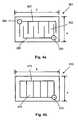
- a semiconductor device 2220 in enclosure 2201can be arranged to accommodate high power surface LED′′s.
- “High power” LED′′smeans that the light output from each LED module is greater than 40 milliwatts.
- “Surface mount” LED′′sare LED′′s mounted directly on a heat sink, or other surface, in contrast with traditional LED lamps which have ordinary electrical leads for wiring and must be separately held in place. High power surface mount LED′′s are described in detail later in this document.
- the heat sink 2204has a plurality of heat sink faces 2210 , 2211 and 2212 which are each generally planar and are arranged in angular orientation with each other in order to cause light from the LED′′s to be dispersed around a space to be illuminated.
- the heat sink facescan be oriented with respect to each other at any desired angle, but 45 degree angles are depicted in the figure so that face 2210 is perpendicular to face 2212 .
- a standard base 2203is provided.
- FIG. 3 adepicts an LED chip with an insulating substrate 201 .
- the substrate 202may be an appropriate material on which a semiconductor may be grown, such as sapphire, gallium arsenide, silicon carbide, gallium phosphorous, gallium nitride and others.
- the substrate 202will also in this embodiment be electrically insulative.
- the semiconductor material 203will emit light in all directions as indicated by arrows 204 a , 204 b , 204 c and 204 d .
- Positive 205 a and negative 205 b electrodesare provided for powering the chip.
- FIG. 3 bdepicts an example of epitaxial layer configuration for the LED of FIG. 3 a .
- a light emitting diode on an electrically insulative substrate 1200is depicted.
- the LEDincludes an electrically insulative substrate such as sapphire 1201 .
- the substrateserves as a carrier, pad or platform on which to grow the chip's epitaxial layers.
- the first layer placed on the substrate 1201is a buffer layer 1202 , in this case a GaN buffer layer. Use of a buffer layer reduces defects in the chip which would otherwise arise due to differences in material properties between the epitaxial layers and the substrate.
- a conductive layer 1203is provided, such as n-GaN. This layer acts as a connector for a negative electrode.
- a cladding layer 1204such as n-AlGaN, is provided. Cladding layers serve to confine the electrons as they jump from a conduction band to valance and give up energy that converts to light.
- An active layer 1205 p-lnGaNis then provided where electrons jump from a conduction band to valance and emit energy which converts to light.
- another cladding layer 1206such as p-AlGaN is provided that also serves to confine electrons.
- a contact layer 1207such as p+-GaN is provided that is doped for Ohmic contact.
- the contact layer 1207has a positive electrode 1208 mounted on it, in this case an electrode that has a mount side on the contact layer 1207 that is Ni and an electrode face that is Au.
- a similar negative electrodeis provide on a shelf of the first cladding layer 1203 .
- FIG. 3 cdepicts an LED with a conducting substrate 210 .
- the substrate 211must be an electrically conductive material on which a semiconductor ship may be grown, such as gallium arsenide, silicon carbide, gallium phosphorous, gallium nitride and others.
- a portion of the substrate 212will serve as an electrode for powering the chip, in this case a negative electrode.
- the semiconductor material 213will emit light in all directions as indicated by arrows 214 a , 214 b , 214 c and 214 d .
- a positive electrode 215is provided, and the base 240 of the substrate 211 acts as a negative electrode.
- the base 240is made of any conductive metal such as Au, Au/Ce, An/Zn and others.
- FIG. 3 ddepicts epitaxial layer configuration for the LED of FIG. 3 c .
- a light emitting diode grown on an electrically conductive substrate 1210is depicted.
- the LEDincludes an electrically conductive substrate such as SiC 1212 .
- the substrateserves as a carrier, pad or platform on which to grow the chip′′s epitaxial layers, and as a negative electrode in the chip.
- the first layer placed on the substrate 1212is a buffer layer 1213 , in this case a GaN buffer layer.
- a cladding layer 1214is provided, such as n-GaN.
- An active layer 1215 p-InGaNis provided where energy is converted to light.
- another cladding layer 1216such as p-AlGaN is provided on the active layer 1215 .
- a contact layer 1217such as p+-GaN that has a positive electrode 1218 mounted on it.
- a negative electrode 1211is provided at the base of the chip.
- FIG. 3 edepicts a VCSEL chip on an insulating substrate 220 .
- the substrate 221has a volume of semiconductor material 222 on it.
- Positive electrodes 223 a and 223 b and negative electrodes 224are provided for powering the chip, and light is emitted from the chip in directions generally indicated by arrows 225 a and 225 b.
- FIG. 3 fdepicts epitaxial layer configuration of the VCSEL chip of FIG. 3 e with an electrically insulative substrate 1220 .
- the chip 1220includes a substrate 1221 that has electrically insulative properties such as sapphire.
- a buffer layer 1222such as GaN followed by a cladding layer and contact layer 1223 such as n-GaN.
- the cladding layer 1223includes a negative electrode 1232 c .
- nGalnN 1224there is another cladding layer nGalnN 1224 .
- a reflective layer AlN/AlGaN MQW (multiple quantum wells) 1225is provided.
- a cladding layer 1226 n-AlGaNis interposed between the reflective layer 1225 and the active layer 1227 GalnN MQW.
- the active layer 1227is followed by another cladding layer p-AlGaN 1228 which is followed by a second reflective layer 1229 AIN/AlGaN MQW.
- Light emitted from the active layerreflects between the two reflective layers until it reaches an appropriate energy level and then lases, emitting a laser beam of light.
- the second reflective layer 1229is followed by a cladding layer p-AlGaN 1230 and a contact layer p+-GaN 1231 .
- the contact layermay be ring-shaped with a window opening 1233 and has one or more positive electrodes 1232 a and 1232 b which are contact areas.
- the negative electrodeis created on the n-GaN layer.
- FIG. 3 gdepicts a VCSEL chip on a conductive substrate 230 .
- the substrate 231has a volume of semiconductor material 232 on it.
- Positive electrodes 233 a and 233 bare provided for powering the chip, and light is emitted from the chip in directions generally indicated by arrows 235 a and 235 b .
- the base 236 of the substrate 231serves as a negative electrode.
- FIG. 3 hdepicts epitaxial layer configuration of a VOSEL chip with an electrically conductive substrate 1239 such as that of FIG. 3 g .
- the chip 1239includes a substrate 1241 that has electrically conductive properties such as SiC.
- the underside of the substrate 1241has an electrode 1240 .
- a buffer layer 1242such as GaN followed by a cladding layer 1243 such as n-GaN.
- NGalnN 1244there is another cladding layer using AlN/AlGaN MQW (multiple quantum wells) 1245 is then provided.
- a cladding layer 1246 n-AlGaNis interposed between the first reflective layer 1245 and the active layer 1247 GalnN MQW.
- the active layer 1247is followed by another cladding layer p-AlGaN 1248 which is followed by a second reflective layer 1429 AlN/AlGaN MOW.
- the second reflective layer 1249is followed by a cladding layer p-AlGaN 1250 and a contact layer p+-GaN 1251 .
- the contact layermay have one or more positive electrodes 1252 a and 1252 b mounted on it.
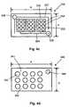
- FIG. 4 adepicts a top view of an LED array on a single chip with a size a ⁇ b on an insulating substrate 301 .
- Each of sizes a and bis greater than 300 micro meters.
- Semiconductor materials 302are located on an electrically insulative substrate (not shown).
- Positive 303 and negative 304 padsare provided, each in electrical connection with its respective metal strip 305 and 306 arranged in a row and column formation (8 columns shown) to create the array and power the chip. This enables the LED to emit high power light from a single chip.
- FIG. 4 bdepicts a top view of an LED array on a single chip with a size a ⁇ b on a conductive substrate 310 .
- Each of sizes a and bis greater than 300 micro meters.
- Semiconductor materials 312are located on an electrically conductive substrate (not shown).
- Positive pad 313is provided in electrical connection with a metal strip 315 arranged in an array formation to power the chip.
- the substrate 310serves as the negative electrode in the embodiment depicted.
- FIG. 4 cdepicts a top view of a VCSEL array on a single chip with a size a ⁇ b on an insulating substrate 320 .
- the chip 320includes an electrically insulative substrate (not shown) on which a semiconductor material 332 is located covered by a panel 333 .
- the panel 333may be an appropriate conductive material such as Au/Ce, Au/Zn and others.
- the panel 333has a plurality of windows 334 in it to permit light produced by the semiconductor material 332 to be emitted for use.
- the panel 333is electrically connected to conductive metal strip 340 and to an electrode pad 335 .
- a negative electrode pad 336is also provided in electrical conduction with a metal strip 337 to power the chip.
- FIG. 4 ddepicts a top view of a VCSEL array on a single chip with a dimension a ⁇ b on a conductive substrate 340 .
- Each of sizes a and bis greater than 300 micro meters. It includes a conductive substrate (not shown) on which a semiconductor material 341 is located.
- a conductive panel 342overlays the semiconductor material 341 .
- a plurality of windows 343are provided in the panel 342 to allow light produced by the chip to escape for us.
- a positive electrode pad 344is provided which in conjunction with the electrically conductive substrate serving as a negative electrode power the chip.
- a negative electrodeis provided on the bottom of the chip 340 .
- FIGS. 5 a and 5 bdepict a semiconductor chip system that emits white light.
- a GaN based semiconductor chip 2000depicted. It includes a GaN system 5001 built on an insulative sapphire substrate 5002 capable of emitting blue light, the general structure of which is known in the prior art.
- a light conversion layer 5003such as AlGaInP (aluminum gallium indium phosphate) adjacent the sapphire layer 5002 opposite the GaN system 5001 . Light emitted from the GaN system will travel through the sapphire layer 5002 , through the AlGaInP 5003 to exit the chip system.
- Electrodes 5005 and 5006are provided for electrical connection.
- the chip 2000is depicted following application of an exterior light conversion coating or layer 5007 such as phosphor. Light which exits through the phosphor such as 5004 a will be converted in wavelength to white, making a useful light for illuminating physical spaces.
- a coating or layer to convert monochromatic light to white lightmay include phosphor powder, YAG/Ce and others. Such a coating or layer may be applied by the methods of brush coating, flow coating and evaporative coating.
- FIG. 6depicts a cross sectional view of a heat sink of the invention 401 .
- a plurality of semiconductor chips or high power LED′′s 402 capable of emitting lightare mounted in a well of the heat sink material 403 (surface mounting).
- the mounting of the chips or high power LED′′smay be achieved by use of a heat-conductive adhesive 404 , or by brazing or mechanical fixation.
- the heat sink material 403is of sufficient thickness to conduct heat away from the chips 402 and keep the chips cool.
- a layer or lining of thermal electric material 405may be installed. Thermal electric (“TE”) material experiences a reduction in temperature when voltage is applied to it.
- TEThermal electric
- the TE materialmay line an air chamber 406 .
- the air chamberis open at its entrance 406 a and at its exit 406 b .
- a fan 407may be placed in or near the air chamber 406 in order to cause air 408 to travel in the entrance 406 a , through the air chamber 406 past the TE material 405 and out of the exit 406 b , carrying heat with it.
- a fitting or connectormay be provided that is threaded 409 a and has an electrode 409 b for installation into a traditional light socket.
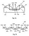
- FIG. 7 adepicts a single chip or single array chip surface mount package 501 . It includes a semiconductor chip or array 502 capable of emitting light mounted in a well 503 of a heat sink 504 .
- the well 503is provided with reflective sides to that light emitted from the sides of the chip or array 502 is reflected out of the well in order to provide useful illumination and to minimize heat buildup.
- the chip or array 502may be mounted in the well 503 by use of a heat conductive adhesive 505 or by brazing or mechanical fixation.
- the heat conductive adhesivemay also be used as a reflector to reflect light from the substrate in the direction of arrows 509 a and 509 b .
- Connection blocks 507 and 508may be mounted on the heat sink 504 in order to facilitate electrical connection of the chip 502 . Light exits the chip as indicated by arrows 509 a , 509 b and 509 c.
- FIG. 7 bdepicts a multiple chip package 520 . It includes multiple wells 521 a , 521 b and 521 c on a heat sink 522 in which multiple chips or arrays 523 a , 523 b and 523 c are located. Connection blocks 524 a , 524 b , 524 c and 524 d are provided with lead wires 525 a , 525 b , 525 c , 525 d and 525 f in order to electrically power the chips or arrays.
- FIG. 8 adepicts a chip package with phosphor covering 601 .
- the packageincludes a heat sink 602 in which a well is located 603 for receiving a chip or array 604 .
- Connection blocks 605 a and 605 b and lead wires 606 a and 606 bmay be used to electrically power the chip or array 604 .
- a thickness of phosphor 607may be placed over the chip or array 604 in order to convert single wavelength light emitted from the chip or array into multiple wavelength white light useful for illumination of spaces used by humans.
- FIG. 8 bdepicts another phosphor coated chip package 6000 . It includes a heat sink 6001 on which a light emitting chip 6002 is mounted in a receptacle 6005 on the heat sink.
- the chip 6002does not fill the entirety of the receptacle 6005 so a transparent filler 6003 of a material transparent to the wavelength of light emitted by the chip 6002 is provided. Some transparent materials which may be used include epoxy, plastic and others.
- a wavelength conversion coating or layer 6004is provided on the face of the chip 6002 opposite the heat sink 6001 to convert the light emitted by the chip to white light. A phosphor coating is preferred.
- FIG. 9depicts a high power surface mount LED package 901 useful in the invention.
- the LED package 901includes a heat sink 902 formed from a material which can dissipate heat.
- a well 904is formed in the heat sink in order to accept an LED, laser diode or semiconductor chip array 903 therein.
- the well 904has walls 905 for reflecting light 906 a and 906 b emitted by the chip(s) 903 .
- An optional phosphor coating 907is provided over the chip(s) to convert light emitted by the chip(s) to white light.
- the chip(s) 903are secured to the heat sink 903 by use of adhesive 908 .
- the adhesive 908may be heat conductive to aid in transmission of heat from the chips to the heat sink, and it may have light reflective properties to aid in reflection of light from the chips in the direction of arrows 906 a and 906 b in a usable direction. Reflection of light by the well and the adhesive provides more efficient light output than would otherwise be achieved.
- Connection blocks 909 a and 909 bare provided for forming electrical connection with diodes 910 a and 910 b .
- a focus dome, lens, or cover 910is provided that is transparent to the light being emitted. The focus dome may have the characteristic of serving to focus light being emitted from the chips in order to create a substantially coherent beam of usable light.
- FIG. 10depicts a light source of the invention 1001 having an LED or laser light source 1002 located in an enclosure 1003 .
- the enclosuremay be any appropriate shape. The depicted shape is that of a bulb, but flat, arcuate, rounded or other shapes may be used depending on the application.
- the enclosure 1003may be glass, plastic, polycarbonate or any other material that is substantially transparent to the light to be emitted.
- the enclosure 1003has an exterior surface 1003 a and an interior surface 1003 b .
- the enclosureserves as a protector of the light source 1002 and it may be designed to diffuse light.
- the interior surface 1003 b of the enclosuremay have a coating or layer 1004 which serves to alter properties of the light emitted from the light source 1002 . For example, if light from the light source 1002 is single wavelength, then the light-altering coating 1004 may be phosphorous which will turn the monochromatic light into white light. Other coatings may be used as desired to alter the light in other ways.
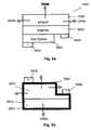
- FIG. 11depicts a power supply module 701 for a light source of the invention.
- the power supply module 701includes a fitting or connector 702 with electrodes 703 and 704 for receiving AC electrical input from a traditional light bulb socket.
- An AC/DC converter 705is provided to convert AC power from standard building wiring into DC power usable by the semiconductor chips of the invention.
- Electrical lead wires 706 a and 706 bare provided for electrical connection to the chips to power the light source, and electrical lead wires 707 a and 707 b are provided to provide power for the cooling fan TE cooler.
- the coatingmay be applied on the interior or exterior of the enclosure, or both.
- heat sink materialsexamples include copper, aluminum, silicon carbide, boron nitride natural diamond, monocrystalline diamond, polycrystalline diamond, polycrystalline diamond compacts, diamond deposited through chemical vapor deposition and diamond deposited through physical vapor deposition. Any materials with adequate heat conductance can be used.
- heat conductive adhesiveswhich may be used are silver based epoxy, other epoxies, and other adhesives with a heat conductive quality. In order to perform a heat conductive function, it is important that the adhesive possess the following characteristics: (i) strong bonding between the materials being bonded, (ii) adequate heat conductance, (iii) electrically insulative or electrically conductive as desired, and (iv) light reflective as desired. Examples of light reflective adhesives which may be used include silver and aluminum based epoxy.
- substrates on which the semiconductors used in the invention may be growninclude Si, GaAs, GaN, InP, sapphire, SiC, GaSb, InAs and others. These may be used for both electrically insulative and electrically conductive substrates.
- thermoelectric coolerMaterials which may be used to used as a thermoelectric cooler in the invention include known semiconductor junction devices.
- the semiconductor light source of the inventionwill emit light in the wavelength range of 200 to 700 in order to be useful for illumination of a physical space used by humans.
- Heat sinks used in this inventioncan be of a variety of shapes and dimensions, such as those depicted in the drawings or any others which are useful for the structure of the particular light source being constructed.
Landscapes
- Engineering & Computer Science (AREA)
- General Engineering & Computer Science (AREA)
- Physics & Mathematics (AREA)
- Microelectronics & Electronic Packaging (AREA)
- Optics & Photonics (AREA)
- Led Device Packages (AREA)
- Led Devices (AREA)
Abstract
Description
Claims (22)
Priority Applications (5)
| Application Number | Priority Date | Filing Date | Title |
|---|---|---|---|
| US09/938,875US6746885B2 (en) | 2001-08-24 | 2001-08-24 | Method for making a semiconductor light source |
| US11/397,323US7728345B2 (en) | 2001-08-24 | 2006-04-04 | Semiconductor light source for illuminating a physical space including a 3-dimensional lead frame |
| US11/938,131US7976211B2 (en) | 2001-08-24 | 2007-11-09 | Light bulb utilizing a replaceable LED light source |
| US12/785,203US8723212B2 (en) | 2001-08-24 | 2010-05-21 | Semiconductor light source |
| US14/038,541US20140021497A1 (en) | 2001-08-24 | 2013-09-26 | Semiconductor light source for illuminating a physical space including a 3-dimensional lead frame |
Applications Claiming Priority (1)
| Application Number | Priority Date | Filing Date | Title |
|---|---|---|---|
| US09/938,875US6746885B2 (en) | 2001-08-24 | 2001-08-24 | Method for making a semiconductor light source |
Related Child Applications (2)
| Application Number | Title | Priority Date | Filing Date |
|---|---|---|---|
| US10/773,123ContinuationUS20040256630A1 (en) | 2001-08-24 | 2004-02-05 | Illuminating light |
| US10/773,123Continuation-In-PartUS20040256630A1 (en) | 2001-08-24 | 2004-02-05 | Illuminating light |
Publications (2)
| Publication Number | Publication Date |
|---|---|
| US20030040200A1 US20030040200A1 (en) | 2003-02-27 |
| US6746885B2true US6746885B2 (en) | 2004-06-08 |
Family
ID=25472117
Family Applications (1)
| Application Number | Title | Priority Date | Filing Date |
|---|---|---|---|
| US09/938,875Expired - LifetimeUS6746885B2 (en) | 2001-08-24 | 2001-08-24 | Method for making a semiconductor light source |
Country Status (1)
| Country | Link |
|---|---|
| US (1) | US6746885B2 (en) |
Cited By (95)
| Publication number | Priority date | Publication date | Assignee | Title |
|---|---|---|---|---|
| US20040195947A1 (en)* | 2003-04-04 | 2004-10-07 | Clark Jason Wilfred | High brightness LED fixture for replacing high intensity dishcharge (HID) lamps |
| US20040229391A1 (en)* | 2003-04-25 | 2004-11-18 | Kazuyuki Ohya | LED lamp manufacturing process |
| US20040257809A1 (en)* | 2003-06-17 | 2004-12-23 | Jeng-Shyong Wu | Function controllable decorative lighting equipment |
| US20050111234A1 (en)* | 2003-11-26 | 2005-05-26 | Lumileds Lighting U.S., Llc | LED lamp heat sink |
| WO2004100213A3 (en)* | 2003-05-05 | 2005-06-30 | Gelcore Llc | Led-based light bulb |
| US20050174780A1 (en)* | 2004-02-06 | 2005-08-11 | Daejin Dmp Co., Ltd. | LED light |
| US20050239227A1 (en)* | 2002-08-30 | 2005-10-27 | Gelcore, Llc | Light emitting diode component |
| US20060245187A1 (en)* | 2005-04-29 | 2006-11-02 | Scott Robert R | Dental curing light with specially arranged LEDs |
| US20080062697A1 (en)* | 2006-09-12 | 2008-03-13 | Swantner Michael J | Illuminated sign and light source for use with said sign |
| WO2008134056A1 (en)* | 2007-04-26 | 2008-11-06 | Deak-Lam Inc. | Photon energy coversion structure |
| US20080310167A1 (en)* | 2007-05-25 | 2008-12-18 | Victor Zaderej | Interconnect device which forms a heat sink and electrical connections between a heat generating device and a power source |
| US20090046473A1 (en)* | 2007-08-13 | 2009-02-19 | Topco Technologies Corp. | Light-emitting diode lamp |
| US20090174301A1 (en)* | 2006-07-21 | 2009-07-09 | Peter Frey | Radiation-emitting device comprising a plurality of radiation-emitting components and illumination device |
| US20090200939A1 (en)* | 2006-05-02 | 2009-08-13 | Superbulbs, Inc. | Method of Light Dispersion and Preferential Scattering of Certain Wavelengths of Light-Emitting Diodes and Bulbs Constructed Therefrom |
| US20090257220A1 (en)* | 2006-05-02 | 2009-10-15 | Superbulbs, Inc. | Plastic led bulb |
| US20090268461A1 (en)* | 2008-04-28 | 2009-10-29 | Deak David G | Photon energy conversion structure |
| US20090309473A1 (en)* | 2006-05-02 | 2009-12-17 | Superbulbs, Inc. | Heat removal design for led bulbs |
| US20100096966A1 (en)* | 2008-10-16 | 2010-04-22 | Yung Pun Cheng | Wide-angle led lighting lamp with high heat-dissipation efficiency and uniform illumination |
| US20100124058A1 (en)* | 2008-11-18 | 2010-05-20 | Miller Michael R | Thermal Management of LED Lighting Systems |
| US20100177496A1 (en)* | 2008-11-25 | 2010-07-15 | Jennifer Gillies | Custom color led replacements for traditional lighting fixtures |
| US20110001422A1 (en)* | 2002-08-30 | 2011-01-06 | Lumination Llc | Light emitting diode component |
| US20110037388A1 (en)* | 2008-04-30 | 2011-02-17 | Zhejiang Manelux Lighting Co., Ltd. | White light emission diode and white light emission diode lamp |
| US20110058379A1 (en)* | 2008-05-08 | 2011-03-10 | Lok-F Gmbh | Lamp Device |
| US20110080740A1 (en)* | 2009-10-02 | 2011-04-07 | Lumination Llc | Led lamp with uniform omnidirectional light intensity output |
| US20110110095A1 (en)* | 2009-10-09 | 2011-05-12 | Intematix Corporation | Solid-state lamps with passive cooling |
| US20110169394A1 (en)* | 2010-01-12 | 2011-07-14 | GE Lighting Solutions, LLC | Transparent thermally conductive polymer composites for light source thermal management |
| US20110204393A1 (en)* | 2008-11-06 | 2011-08-25 | Rohm Co., Ltd. | Led lamp |
| US20120147600A1 (en)* | 2008-09-08 | 2012-06-14 | Intematix Corporation | Light emitting diode (led) lamps |
| US20120155084A1 (en)* | 2010-12-15 | 2012-06-21 | Kinpo Electronics, Inc. | Lighting apparatus |
| WO2012096757A1 (en) | 2011-01-13 | 2012-07-19 | GE Lighting Solutions, LLC | Omnidirectional led based solid state lamp |
| US8227961B2 (en) | 2010-06-04 | 2012-07-24 | Cree, Inc. | Lighting device with reverse tapered heatsink |
| US20120224371A1 (en)* | 2011-03-02 | 2012-09-06 | Kinpo Electronics, Inc. | Lighting apparatus |
| US8272762B2 (en) | 2010-09-28 | 2012-09-25 | Lighting Science Group Corporation | LED luminaire |
| US20120307493A1 (en)* | 2010-02-23 | 2012-12-06 | C/O Toshiba Lighting & Technology Corporation | Lamp with Ferrule and Lighting Apparatus Using the Same |
| CN103016987A (en)* | 2012-12-18 | 2013-04-03 | 居学良 | led light bulb |
| US8415695B2 (en) | 2007-10-24 | 2013-04-09 | Switch Bulb Company, Inc. | Diffuser for LED light sources |
| US8439528B2 (en) | 2007-10-03 | 2013-05-14 | Switch Bulb Company, Inc. | Glass LED light bulbs |
| US20130258697A1 (en)* | 2012-04-02 | 2013-10-03 | Hyundai Motor Japan R&D Center Inc. | Polyhedron type lamp for vehicle |
| US8568140B2 (en) | 1998-01-20 | 2013-10-29 | Jozef Kovac | Apparatus and method for curing materials with radiation |
| US8575836B2 (en) | 2010-06-08 | 2013-11-05 | Cree, Inc. | Lighting devices with differential light transmission regions |
| US8591062B2 (en) | 2012-04-13 | 2013-11-26 | Cree, Inc. | LED lamp |
| US8591069B2 (en) | 2011-09-21 | 2013-11-26 | Switch Bulb Company, Inc. | LED light bulb with controlled color distribution using quantum dots |
| US8596821B2 (en) | 2010-06-08 | 2013-12-03 | Cree, Inc. | LED light bulbs |
| US8616714B2 (en) | 2011-10-06 | 2013-12-31 | Intematix Corporation | Solid-state lamps with improved radial emission and thermal performance |
| US20140003048A1 (en)* | 2010-03-03 | 2014-01-02 | Cree, Inc. | Led based pedestal-type lighting structure |
| US8710764B2 (en) | 2008-04-07 | 2014-04-29 | Metrospec Technology Llc | Solid state lighting circuit and controls |
| US8752983B2 (en) | 2012-04-13 | 2014-06-17 | Cree, Inc. | Gas cooled LED lamp |
| US20140268700A1 (en)* | 2013-03-15 | 2014-09-18 | International Development LLC | Multisided area-illuminating device |
| US8851356B1 (en) | 2008-02-14 | 2014-10-07 | Metrospec Technology, L.L.C. | Flexible circuit board interconnection and methods |
| US8968006B1 (en) | 2008-03-18 | 2015-03-03 | Metrospec Technology, Llc | Circuit board having a plated through hole passing through conductive pads on top and bottom sides of the board and the board |
| US8967838B1 (en) | 2004-03-13 | 2015-03-03 | David Christopher Miller | Flexible LED substrate capable of being formed into a concave LED light source, concave light sources so formed and methods of so forming concave LED light sources |
| US8992051B2 (en) | 2011-10-06 | 2015-03-31 | Intematix Corporation | Solid-state lamps with improved radial emission and thermal performance |
| CN104595806A (en)* | 2015-01-16 | 2015-05-06 | 浙江寰龙电子技术有限公司 | LED (light emitting diode) spot lamp with wider light irradiation range |
| US9052093B2 (en) | 2013-03-14 | 2015-06-09 | Cree, Inc. | LED lamp and heat sink |
| US9057511B2 (en) | 2010-03-03 | 2015-06-16 | Cree, Inc. | High efficiency solid state lamp and bulb |
| US9062830B2 (en) | 2010-03-03 | 2015-06-23 | Cree, Inc. | High efficiency solid state lamp and bulb |
| US9062867B2 (en) | 2012-12-12 | 2015-06-23 | Cree, Inc. | LED lamp |
| US9068701B2 (en) | 2012-01-26 | 2015-06-30 | Cree, Inc. | Lamp structure with remote LED light source |
| US9066777B2 (en) | 2009-04-02 | 2015-06-30 | Kerr Corporation | Curing light device |
| AU2010300448B2 (en)* | 2009-10-02 | 2015-07-02 | GE Lighting Solutions, LLC | Light emitting diode (LED) based lamp |
| US9072572B2 (en) | 2009-04-02 | 2015-07-07 | Kerr Corporation | Dental light device |
| US9234655B2 (en) | 2011-02-07 | 2016-01-12 | Cree, Inc. | Lamp with remote LED light source and heat dissipating elements |
| US9234638B2 (en) | 2012-04-13 | 2016-01-12 | Cree, Inc. | LED lamp with thermally conductive enclosure |
| USD748296S1 (en) | 2013-03-14 | 2016-01-26 | Cree, Inc. | LED lamp |
| US9273835B2 (en) | 2010-12-08 | 2016-03-01 | Cree, Inc. | Linear LED lamp |
| US9275979B2 (en) | 2010-03-03 | 2016-03-01 | Cree, Inc. | Enhanced color rendering index emitter through phosphor separation |
| US9310065B2 (en) | 2012-04-13 | 2016-04-12 | Cree, Inc. | Gas cooled LED lamp |
| US9310028B2 (en) | 2012-04-13 | 2016-04-12 | Cree, Inc. | LED lamp with LEDs having a longitudinally directed emission profile |
| US9310030B2 (en) | 2010-03-03 | 2016-04-12 | Cree, Inc. | Non-uniform diffuser to scatter light into uniform emission pattern |
| US9316361B2 (en) | 2010-03-03 | 2016-04-19 | Cree, Inc. | LED lamp with remote phosphor and diffuser configuration |
| US9322543B2 (en) | 2012-04-13 | 2016-04-26 | Cree, Inc. | Gas cooled LED lamp with heat conductive submount |
| US9341355B2 (en) | 2008-03-06 | 2016-05-17 | Metrospec Technology, L.L.C. | Layered structure for use with high power light emitting diode systems |
| US9360188B2 (en) | 2014-02-20 | 2016-06-07 | Cree, Inc. | Remote phosphor element filled with transparent material and method for forming multisection optical elements |
| US9395074B2 (en) | 2012-04-13 | 2016-07-19 | Cree, Inc. | LED lamp with LED assembly on a heat sink tower |
| US9395051B2 (en) | 2012-04-13 | 2016-07-19 | Cree, Inc. | Gas cooled LED lamp |
| US9412926B2 (en) | 2005-06-10 | 2016-08-09 | Cree, Inc. | High power solid-state lamp |
| US20160230936A9 (en)* | 2007-06-08 | 2016-08-11 | A66, Inc. | Light Bulb with Automated Emergency Operation |
| US9423116B2 (en) | 2013-12-11 | 2016-08-23 | Cree, Inc. | LED lamp and modular lighting system |
| US9488359B2 (en) | 2012-03-26 | 2016-11-08 | Cree, Inc. | Passive phase change radiators for LED lamps and fixtures |
| US9500325B2 (en) | 2010-03-03 | 2016-11-22 | Cree, Inc. | LED lamp incorporating remote phosphor with heat dissipation features |
| US9625105B2 (en) | 2010-03-03 | 2017-04-18 | Cree, Inc. | LED lamp with active cooling element |
| US9726330B2 (en) | 2013-12-20 | 2017-08-08 | Cree, Inc. | LED lamp |
| US9761775B2 (en) | 2001-08-24 | 2017-09-12 | Epistar Corporation | Semiconductor light source |
| US9841175B2 (en) | 2012-05-04 | 2017-12-12 | GE Lighting Solutions, LLC | Optics system for solid state lighting apparatus |
| US9951938B2 (en) | 2009-10-02 | 2018-04-24 | GE Lighting Solutions, LLC | LED lamp |
| US9951909B2 (en) | 2012-04-13 | 2018-04-24 | Cree, Inc. | LED lamp |
| US10077874B2 (en) | 2016-05-31 | 2018-09-18 | Ledvance Llc | Light emitting diode (LED) lamp with top-emitting LEDs mounted on a planar PC board |
| US10334735B2 (en) | 2008-02-14 | 2019-06-25 | Metrospec Technology, L.L.C. | LED lighting systems and methods |
| US10340424B2 (en) | 2002-08-30 | 2019-07-02 | GE Lighting Solutions, LLC | Light emitting diode component |
| US10359151B2 (en) | 2010-03-03 | 2019-07-23 | Ideal Industries Lighting Llc | Solid state lamp with thermal spreading elements and light directing optics |
| US10451251B2 (en) | 2010-08-02 | 2019-10-22 | Ideal Industries Lighting, LLC | Solid state lamp with light directing optics and diffuser |
| US10665762B2 (en) | 2010-03-03 | 2020-05-26 | Ideal Industries Lighting Llc | LED lamp incorporating remote phosphor and diffuser with heat dissipation features |
| US10849200B2 (en) | 2018-09-28 | 2020-11-24 | Metrospec Technology, L.L.C. | Solid state lighting circuit with current bias and method of controlling thereof |
| US11251164B2 (en) | 2011-02-16 | 2022-02-15 | Creeled, Inc. | Multi-layer conversion material for down conversion in solid state lighting |
| US11266014B2 (en) | 2008-02-14 | 2022-03-01 | Metrospec Technology, L.L.C. | LED lighting systems and method |
Families Citing this family (46)
| Publication number | Priority date | Publication date | Assignee | Title |
|---|---|---|---|---|
| US6905900B1 (en) | 2000-11-28 | 2005-06-14 | Finisar Corporation | Versatile method and system for single mode VCSELs |
| US6692252B2 (en) | 2001-12-17 | 2004-02-17 | Ultradent Products, Inc. | Heat sink with geometric arrangement of LED surfaces |
| US20030148242A1 (en)* | 2002-02-05 | 2003-08-07 | Fischer Dan E. | Lightweight hand held dental curing device |
| US7106523B2 (en) | 2002-01-11 | 2006-09-12 | Ultradent Products, Inc. | Optical lens used to focus led light |
| US6940659B2 (en)* | 2002-01-11 | 2005-09-06 | Ultradent Products, Inc. | Cone-shaped lens having increased forward light intensity and kits incorporating such lenses |
| US6702576B2 (en) | 2002-02-22 | 2004-03-09 | Ultradent Products, Inc. | Light-curing device with detachably interconnecting light applicator |
| USRE47011E1 (en) | 2002-05-29 | 2018-08-28 | Optolum, Inc. | Light emitting diode light source |
| US6573536B1 (en) | 2002-05-29 | 2003-06-03 | Optolum, Inc. | Light emitting diode light source |
| US6965626B2 (en)* | 2002-09-03 | 2005-11-15 | Finisar Corporation | Single mode VCSEL |
| US20040101802A1 (en)* | 2002-11-21 | 2004-05-27 | Scott Robert R. | Wide bandwidth led curing light |
| US6994546B2 (en)* | 2002-12-18 | 2006-02-07 | Ultradent Products, Inc. | Light curing device with detachable power supply |
| US6890175B2 (en)* | 2002-12-18 | 2005-05-10 | Ultradent Products, Inc. | Cooling system for hand-held curing light |
| USD530013S1 (en) | 2003-02-18 | 2006-10-10 | Ultradent Products, Inc. | Dental illumination device |
| US20040214130A1 (en)* | 2003-04-25 | 2004-10-28 | Ultradent Products, Inc. | Flexible translucent protective covers used to protect dental appliances from rigid light emitting devices |
| US20040214131A1 (en)* | 2003-04-25 | 2004-10-28 | Ultradent Products, Inc., | Spot curing lens used to spot cure a dental appliance adhesive and systems and methods employing such lenses |
| KR101034055B1 (en)* | 2003-07-18 | 2011-05-12 | 엘지이노텍 주식회사 | Light emitting diodes and manufacturing method |
| US7192276B2 (en)* | 2003-08-20 | 2007-03-20 | Ultradent Products, Inc. | Dental curing light adapted to emit light at a desired angle |
| US7144250B2 (en) | 2003-12-17 | 2006-12-05 | Ultradent Products, Inc. | Rechargeable dental curing light |
| US7195482B2 (en)* | 2003-12-30 | 2007-03-27 | Ultradent Products, Inc. | Dental curing device having a heat sink for dissipating heat |
| US7074040B2 (en)* | 2004-03-30 | 2006-07-11 | Ultradent Products, Inc. | Ball lens for use with a dental curing light |
| US11320129B1 (en) | 2004-10-05 | 2022-05-03 | Steven Michael Colby | LED bulb including pulse generator and/or AC/DC converter |
| US9874332B1 (en)* | 2013-01-15 | 2018-01-23 | Steven Michael Colby | Bulb including removable cover |
| US7056116B2 (en)* | 2004-10-26 | 2006-06-06 | Ultradent Products, Inc. | Heat sink for dental curing light comprising a plurality of different materials |
| WO2006104553A1 (en)* | 2005-03-25 | 2006-10-05 | Five Star Import Group L.L.C. | Led light bulb |
| US20070037113A1 (en)* | 2005-08-10 | 2007-02-15 | Scott Robert R | Dental curing light including a light integrator for providing substantially equal distribution of each emitted wavelength |
| US20070120138A1 (en)* | 2005-11-28 | 2007-05-31 | Visteon Global Technologies, Inc. | Multi-layer light emitting device with integrated thermoelectric chip |
| US20070128577A1 (en)* | 2005-12-05 | 2007-06-07 | Ultradent Products, Inc. | Dental curing lights including a capacitor power source |
| WO2008037940A1 (en)* | 2006-09-26 | 2008-04-03 | Ghollam Tahmosybayat | Lamp assembly |
| DE102007042978A1 (en)* | 2007-09-10 | 2009-03-12 | Osram Gesellschaft mit beschränkter Haftung | lamp |
| US8206009B2 (en)* | 2007-09-19 | 2012-06-26 | Cooper Technologies Company | Light emitting diode lamp source |
| ITNA20080011A1 (en)* | 2008-02-15 | 2009-08-16 | Self Sime Italia Ricerca & Sviluppo Srl | LED POWER LAMP FOR LIGHTS LANTERNS. |
| AT524690B1 (en)* | 2008-07-24 | 2022-08-15 | Tridonic Gmbh & Co Kg | LAMPS WITH LED |
| GB2462815A (en)* | 2008-08-18 | 2010-02-24 | Sensitive Electronic Co Ltd | Light emitting diode lamp |
| US20100301356A1 (en)* | 2009-06-02 | 2010-12-02 | Bridgelux, Inc. | Light source having light emitting cells arranged to produce a spherical emission pattern |
| US8058782B2 (en)* | 2010-03-10 | 2011-11-15 | Chicony Power Technology Co., Ltd. | Bulb-type LED lamp |
| DE102010013310B4 (en) | 2010-03-29 | 2012-02-23 | Panasonic Electric Works Vossloh-Schwabe Gmbh | Operating circuit for operating a fan for a light module |
| TW201135151A (en)* | 2010-04-09 | 2011-10-16 | Wang Xiang Yun | Illumination structure |
| CN101852382A (en)* | 2010-06-10 | 2010-10-06 | 洛克斯(吴江)电子有限公司 | Lamp shade for LED lamp |
| CN102003642A (en)* | 2010-08-31 | 2011-04-06 | 林世凯 | Laser bulb and camera with laser bulb |
| WO2012072127A1 (en)* | 2010-12-01 | 2012-06-07 | M & R Automation Gmbh | Led light bulb |
| TWI491830B (en)* | 2012-02-14 | 2015-07-11 | Av Tech Corp | Variable beam illumination device and assembly method thereof |
| CN103363319A (en)* | 2012-03-29 | 2013-10-23 | 苏州盟泰励宝光电有限公司 | Self-ballasted led lamp |
| CN103851372B (en)* | 2012-12-04 | 2016-06-29 | 展晶科技(深圳)有限公司 | Light emitting diode bulb |
| CN103388763B (en)* | 2013-07-25 | 2015-08-19 | 江苏昌泽电子有限公司 | A kind of LED bulb |
| CN104061470B (en)* | 2014-06-26 | 2016-08-31 | 成都绿洲电子有限公司 | A kind of LED matrix |
| CN114024208B (en)* | 2021-11-09 | 2024-12-03 | 江苏集萃中科纳米科技有限公司 | A conduction-cooled semiconductor laser with replaceable chips |
Citations (21)
| Publication number | Priority date | Publication date | Assignee | Title |
|---|---|---|---|---|
| US4675575A (en) | 1984-07-13 | 1987-06-23 | E & G Enterprises | Light-emitting diode assemblies and systems therefore |
| US4727289A (en) | 1985-07-22 | 1988-02-23 | Stanley Electric Co., Ltd. | LED lamp |
| US5160200A (en) | 1991-03-06 | 1992-11-03 | R & D Molded Products, Inc. | Wedge-base LED bulb housing |
| US5463280A (en) | 1994-03-03 | 1995-10-31 | National Service Industries, Inc. | Light emitting diode retrofit lamp |
| US5575459A (en) | 1995-04-27 | 1996-11-19 | Uniglo Canada Inc. | Light emitting diode lamp |
| US5655830A (en) | 1993-12-01 | 1997-08-12 | General Signal Corporation | Lighting device |
| US5688042A (en) | 1995-11-17 | 1997-11-18 | Lumacell, Inc. | LED lamp |
| US5765940A (en)* | 1995-10-31 | 1998-06-16 | Dialight Corporation | LED-illuminated stop/tail lamp assembly |
| US5806965A (en) | 1996-01-30 | 1998-09-15 | R&M Deese, Inc. | LED beacon light |
| US5813752A (en)* | 1997-05-27 | 1998-09-29 | Philips Electronics North America Corporation | UV/blue LED-phosphor device with short wave pass, long wave pass band pass and peroit filters |
| US5890794A (en) | 1996-04-03 | 1999-04-06 | Abtahi; Homayoon | Lighting units |
| US5941626A (en) | 1996-05-01 | 1999-08-24 | Hiyoshi Electric Co., Ltd. | Long light emitting apparatus |
| US5947588A (en) | 1997-10-06 | 1999-09-07 | Grand General Accessories Manufacturing Inc. | Light fixture with an LED light bulb having a conventional connection post |
| US5982092A (en) | 1997-10-06 | 1999-11-09 | Chen; Hsing | Light Emitting Diode planar light source with blue light or ultraviolet ray-emitting luminescent crystal with optional UV filter |
| US6045240A (en)* | 1996-06-27 | 2000-04-04 | Relume Corporation | LED lamp assembly with means to conduct heat away from the LEDS |
| US6149283A (en)* | 1998-12-09 | 2000-11-21 | Rensselaer Polytechnic Institute (Rpi) | LED lamp with reflector and multicolor adjuster |
| US6220722B1 (en) | 1998-09-17 | 2001-04-24 | U.S. Philips Corporation | Led lamp |
| US6502952B1 (en)* | 1999-06-23 | 2003-01-07 | Fred Jack Hartley | Light emitting diode assembly for flashlights |
| US6561680B1 (en)* | 2000-11-14 | 2003-05-13 | Kelvin Shih | Light emitting diode with thermally conductive structure |
| US6577073B2 (en)* | 2000-05-31 | 2003-06-10 | Matsushita Electric Industrial Co., Ltd. | Led lamp |
| US6580228B1 (en)* | 2000-08-22 | 2003-06-17 | Light Sciences Corporation | Flexible substrate mounted solid-state light sources for use in line current lamp sockets |
- 2001
- 2001-08-24USUS09/938,875patent/US6746885B2/ennot_activeExpired - Lifetime
Patent Citations (22)
| Publication number | Priority date | Publication date | Assignee | Title |
|---|---|---|---|---|
| US4675575A (en) | 1984-07-13 | 1987-06-23 | E & G Enterprises | Light-emitting diode assemblies and systems therefore |
| US4727289A (en) | 1985-07-22 | 1988-02-23 | Stanley Electric Co., Ltd. | LED lamp |
| US5160200A (en) | 1991-03-06 | 1992-11-03 | R & D Molded Products, Inc. | Wedge-base LED bulb housing |
| US5655830A (en) | 1993-12-01 | 1997-08-12 | General Signal Corporation | Lighting device |
| US5463280A (en) | 1994-03-03 | 1995-10-31 | National Service Industries, Inc. | Light emitting diode retrofit lamp |
| US5575459A (en) | 1995-04-27 | 1996-11-19 | Uniglo Canada Inc. | Light emitting diode lamp |
| US5765940A (en)* | 1995-10-31 | 1998-06-16 | Dialight Corporation | LED-illuminated stop/tail lamp assembly |
| US5688042A (en) | 1995-11-17 | 1997-11-18 | Lumacell, Inc. | LED lamp |
| US5806965A (en) | 1996-01-30 | 1998-09-15 | R&M Deese, Inc. | LED beacon light |
| US5890794A (en) | 1996-04-03 | 1999-04-06 | Abtahi; Homayoon | Lighting units |
| US5941626A (en) | 1996-05-01 | 1999-08-24 | Hiyoshi Electric Co., Ltd. | Long light emitting apparatus |
| US6045240A (en)* | 1996-06-27 | 2000-04-04 | Relume Corporation | LED lamp assembly with means to conduct heat away from the LEDS |
| US5813752A (en)* | 1997-05-27 | 1998-09-29 | Philips Electronics North America Corporation | UV/blue LED-phosphor device with short wave pass, long wave pass band pass and peroit filters |
| US5947588A (en) | 1997-10-06 | 1999-09-07 | Grand General Accessories Manufacturing Inc. | Light fixture with an LED light bulb having a conventional connection post |
| US5982092A (en) | 1997-10-06 | 1999-11-09 | Chen; Hsing | Light Emitting Diode planar light source with blue light or ultraviolet ray-emitting luminescent crystal with optional UV filter |
| US6220722B1 (en) | 1998-09-17 | 2001-04-24 | U.S. Philips Corporation | Led lamp |
| US6499860B2 (en)* | 1998-09-17 | 2002-12-31 | Koninklijke Philips Electronics N.V. | Solid state display light |
| US6149283A (en)* | 1998-12-09 | 2000-11-21 | Rensselaer Polytechnic Institute (Rpi) | LED lamp with reflector and multicolor adjuster |
| US6502952B1 (en)* | 1999-06-23 | 2003-01-07 | Fred Jack Hartley | Light emitting diode assembly for flashlights |
| US6577073B2 (en)* | 2000-05-31 | 2003-06-10 | Matsushita Electric Industrial Co., Ltd. | Led lamp |
| US6580228B1 (en)* | 2000-08-22 | 2003-06-17 | Light Sciences Corporation | Flexible substrate mounted solid-state light sources for use in line current lamp sockets |
| US6561680B1 (en)* | 2000-11-14 | 2003-05-13 | Kelvin Shih | Light emitting diode with thermally conductive structure |
Non-Patent Citations (1)
| Title |
|---|
| Schewber, Bill, "LEDs move from indication to illumination", EDN magazine (Aug. 2, 2001) pp. 75, 76, 78, 80, and 82. |
Cited By (156)
| Publication number | Priority date | Publication date | Assignee | Title |
|---|---|---|---|---|
| US9622839B2 (en) | 1998-01-20 | 2017-04-18 | Kerr Corporation | Apparatus and method for curing materials with radiation |
| US9572643B2 (en) | 1998-01-20 | 2017-02-21 | Kerr Corporation | Apparatus and method for curing materials with radiation |
| US8568140B2 (en) | 1998-01-20 | 2013-10-29 | Jozef Kovac | Apparatus and method for curing materials with radiation |
| US9761775B2 (en) | 2001-08-24 | 2017-09-12 | Epistar Corporation | Semiconductor light source |
| US20110001422A1 (en)* | 2002-08-30 | 2011-01-06 | Lumination Llc | Light emitting diode component |
| US20050239227A1 (en)* | 2002-08-30 | 2005-10-27 | Gelcore, Llc | Light emitting diode component |
| US20110018014A1 (en)* | 2002-08-30 | 2011-01-27 | Lumination Llc | Light emitting diode component |
| US8436380B2 (en)* | 2002-08-30 | 2013-05-07 | GE Lighting Solutions, LLC | Light emitting diode component |
| US8362695B2 (en) | 2002-08-30 | 2013-01-29 | GE Lighting Solutions, LLC | Light emitting diode component |
| US7224000B2 (en)* | 2002-08-30 | 2007-05-29 | Lumination, Llc | Light emitting diode component |
| US10340424B2 (en) | 2002-08-30 | 2019-07-02 | GE Lighting Solutions, LLC | Light emitting diode component |
| US20040195947A1 (en)* | 2003-04-04 | 2004-10-07 | Clark Jason Wilfred | High brightness LED fixture for replacing high intensity dishcharge (HID) lamps |
| US20040229391A1 (en)* | 2003-04-25 | 2004-11-18 | Kazuyuki Ohya | LED lamp manufacturing process |
| US20070267976A1 (en)* | 2003-05-05 | 2007-11-22 | Bohler Christopher L | Led-Based Light Bulb |
| WO2004100213A3 (en)* | 2003-05-05 | 2005-06-30 | Gelcore Llc | Led-based light bulb |
| US20040257809A1 (en)* | 2003-06-17 | 2004-12-23 | Jeng-Shyong Wu | Function controllable decorative lighting equipment |
| US6971765B2 (en)* | 2003-06-17 | 2005-12-06 | Jeng-Shyong Wu | Function controllable decorative lighting equipment |
| US7144135B2 (en)* | 2003-11-26 | 2006-12-05 | Philips Lumileds Lighting Company, Llc | LED lamp heat sink |
| US20050111234A1 (en)* | 2003-11-26 | 2005-05-26 | Lumileds Lighting U.S., Llc | LED lamp heat sink |
| US7524089B2 (en)* | 2004-02-06 | 2009-04-28 | Daejin Dmp Co., Ltd. | LED light |
| US20050174780A1 (en)* | 2004-02-06 | 2005-08-11 | Daejin Dmp Co., Ltd. | LED light |
| US8967838B1 (en) | 2004-03-13 | 2015-03-03 | David Christopher Miller | Flexible LED substrate capable of being formed into a concave LED light source, concave light sources so formed and methods of so forming concave LED light sources |
| US7210814B2 (en) | 2005-04-29 | 2007-05-01 | Ultradent Products, Inc. | Dental curing light with specially arranged LEDs |
| US20060245187A1 (en)* | 2005-04-29 | 2006-11-02 | Scott Robert R | Dental curing light with specially arranged LEDs |
| US9412926B2 (en) | 2005-06-10 | 2016-08-09 | Cree, Inc. | High power solid-state lamp |
| US20090309473A1 (en)* | 2006-05-02 | 2009-12-17 | Superbulbs, Inc. | Heat removal design for led bulbs |
| US8569949B2 (en) | 2006-05-02 | 2013-10-29 | Switch Bulb Company, Inc. | Method of light dispersion and preferential scattering of certain wavelengths of light-emitting diodes and bulbs constructed therefrom |
| US20090257220A1 (en)* | 2006-05-02 | 2009-10-15 | Superbulbs, Inc. | Plastic led bulb |
| US8853921B2 (en) | 2006-05-02 | 2014-10-07 | Switch Bulb Company, Inc. | Heat removal design for LED bulbs |
| US20090200939A1 (en)* | 2006-05-02 | 2009-08-13 | Superbulbs, Inc. | Method of Light Dispersion and Preferential Scattering of Certain Wavelengths of Light-Emitting Diodes and Bulbs Constructed Therefrom |
| US8547002B2 (en) | 2006-05-02 | 2013-10-01 | Switch Bulb Company, Inc. | Heat removal design for LED bulbs |
| US8702257B2 (en) | 2006-05-02 | 2014-04-22 | Switch Bulb Company, Inc. | Plastic LED bulb |
| US8193702B2 (en) | 2006-05-02 | 2012-06-05 | Switch Bulb Company, Inc. | Method of light dispersion and preferential scattering of certain wavelengths of light-emitting diodes and bulbs constructed therefrom |
| US8704442B2 (en) | 2006-05-02 | 2014-04-22 | Switch Bulb Company, Inc. | Method of light dispersion and preferential scattering of certain wavelengths of light for light-emitting diodes and bulbs constructed therefrom |
| US20090174301A1 (en)* | 2006-07-21 | 2009-07-09 | Peter Frey | Radiation-emitting device comprising a plurality of radiation-emitting components and illumination device |
| US7600890B2 (en)* | 2006-09-12 | 2009-10-13 | Osram Sylvania Inc. | Illuminated sign and light source for use with said sign |
| US20080062697A1 (en)* | 2006-09-12 | 2008-03-13 | Swantner Michael J | Illuminated sign and light source for use with said sign |
| WO2008134056A1 (en)* | 2007-04-26 | 2008-11-06 | Deak-Lam Inc. | Photon energy coversion structure |
| US7992294B2 (en) | 2007-05-25 | 2011-08-09 | Molex Incorporated | Method of manufacturing an interconnect device which forms a heat sink and electrical connections between a heat generating device and a power source |
| US20080310167A1 (en)* | 2007-05-25 | 2008-12-18 | Victor Zaderej | Interconnect device which forms a heat sink and electrical connections between a heat generating device and a power source |
| US20080307646A1 (en)* | 2007-05-25 | 2008-12-18 | Victor Zaderej | Method of manufacturing an interconnect device which forms a heat sink and electrical connections between a heat generating device and a power source |
| US20160230936A9 (en)* | 2007-06-08 | 2016-08-11 | A66, Inc. | Light Bulb with Automated Emergency Operation |
| US9557012B2 (en)* | 2007-06-08 | 2017-01-31 | A66, Inc. | Light bulb with automated emergency operation |
| US20090046473A1 (en)* | 2007-08-13 | 2009-02-19 | Topco Technologies Corp. | Light-emitting diode lamp |
| US7874710B2 (en)* | 2007-08-13 | 2011-01-25 | Top Energy Saving System Corp. | Light-emitting diode lamp |
| US8752984B2 (en) | 2007-10-03 | 2014-06-17 | Switch Bulb Company, Inc. | Glass LED light bulbs |
| US8439528B2 (en) | 2007-10-03 | 2013-05-14 | Switch Bulb Company, Inc. | Glass LED light bulbs |
| US8415695B2 (en) | 2007-10-24 | 2013-04-09 | Switch Bulb Company, Inc. | Diffuser for LED light sources |
| US8981405B2 (en) | 2007-10-24 | 2015-03-17 | Switch Bulb Company, Inc. | Diffuser for LED light sources |
| US11266014B2 (en) | 2008-02-14 | 2022-03-01 | Metrospec Technology, L.L.C. | LED lighting systems and method |
| US11690172B2 (en) | 2008-02-14 | 2023-06-27 | Metrospec Technology, L.L.C. | LED lighting systems and methods |
| US9736946B2 (en) | 2008-02-14 | 2017-08-15 | Metrospec Technology, L.L.C. | Flexible circuit board interconnection and methods |
| US10334735B2 (en) | 2008-02-14 | 2019-06-25 | Metrospec Technology, L.L.C. | LED lighting systems and methods |
| US8851356B1 (en) | 2008-02-14 | 2014-10-07 | Metrospec Technology, L.L.C. | Flexible circuit board interconnection and methods |
| US10499511B2 (en) | 2008-02-14 | 2019-12-03 | Metrospec Technology, L.L.C. | Flexible circuit board interconnection and methods |
| US11304308B2 (en) | 2008-02-14 | 2022-04-12 | Metrospec Technology, L.L.C. | Flexible circuit board interconnection and methods |
| US9341355B2 (en) | 2008-03-06 | 2016-05-17 | Metrospec Technology, L.L.C. | Layered structure for use with high power light emitting diode systems |
| US9357639B2 (en) | 2008-03-18 | 2016-05-31 | Metrospec Technology, L.L.C. | Circuit board having a plated through hole through a conductive pad |
| US8968006B1 (en) | 2008-03-18 | 2015-03-03 | Metrospec Technology, Llc | Circuit board having a plated through hole passing through conductive pads on top and bottom sides of the board and the board |
| US8710764B2 (en) | 2008-04-07 | 2014-04-29 | Metrospec Technology Llc | Solid state lighting circuit and controls |
| US20090268461A1 (en)* | 2008-04-28 | 2009-10-29 | Deak David G | Photon energy conversion structure |
| US20110037388A1 (en)* | 2008-04-30 | 2011-02-17 | Zhejiang Manelux Lighting Co., Ltd. | White light emission diode and white light emission diode lamp |
| US20110058379A1 (en)* | 2008-05-08 | 2011-03-10 | Lok-F Gmbh | Lamp Device |
| US8456077B2 (en)* | 2008-05-08 | 2013-06-04 | Lok-F Gmbh | Lamp device comprising illuminates surrounded by solid particles comprising a particle number density gradient in a direction away from the illuminates |
| US20120147600A1 (en)* | 2008-09-08 | 2012-06-14 | Intematix Corporation | Light emitting diode (led) lamps |
| US20100096966A1 (en)* | 2008-10-16 | 2010-04-22 | Yung Pun Cheng | Wide-angle led lighting lamp with high heat-dissipation efficiency and uniform illumination |
| US7936119B2 (en) | 2008-10-16 | 2011-05-03 | Yung Pun Cheng | Wide-angle LED lighting lamp with high heat-dissipation efficiency and uniform illumination |
| US20110204393A1 (en)* | 2008-11-06 | 2011-08-25 | Rohm Co., Ltd. | Led lamp |
| US8698290B2 (en)* | 2008-11-06 | 2014-04-15 | Rohm Co., Ltd. | LED lamp |
| CN102203501A (en)* | 2008-11-06 | 2011-09-28 | 罗姆股份有限公司 | Led lamp |
| US20100124058A1 (en)* | 2008-11-18 | 2010-05-20 | Miller Michael R | Thermal Management of LED Lighting Systems |
| US8240885B2 (en) | 2008-11-18 | 2012-08-14 | Abl Ip Holding Llc | Thermal management of LED lighting systems |
| US20100177496A1 (en)* | 2008-11-25 | 2010-07-15 | Jennifer Gillies | Custom color led replacements for traditional lighting fixtures |
| US8360617B2 (en)* | 2008-11-25 | 2013-01-29 | Samsung Electronics Co., Ltd. | Lighting system including LED with glass-coated quantum-dots |
| US9987110B2 (en) | 2009-04-02 | 2018-06-05 | Kerr Corporation | Dental light device |
| US9693846B2 (en) | 2009-04-02 | 2017-07-04 | Kerr Corporation | Dental light device |
| US9730778B2 (en) | 2009-04-02 | 2017-08-15 | Kerr Corporation | Curing light device |
| US9072572B2 (en) | 2009-04-02 | 2015-07-07 | Kerr Corporation | Dental light device |
| US9066777B2 (en) | 2009-04-02 | 2015-06-30 | Kerr Corporation | Curing light device |
| AU2010300448B2 (en)* | 2009-10-02 | 2015-07-02 | GE Lighting Solutions, LLC | Light emitting diode (LED) based lamp |
| US20110080740A1 (en)* | 2009-10-02 | 2011-04-07 | Lumination Llc | Led lamp with uniform omnidirectional light intensity output |
| US9951938B2 (en) | 2009-10-02 | 2018-04-24 | GE Lighting Solutions, LLC | LED lamp |
| US20160356431A1 (en)* | 2009-10-02 | 2016-12-08 | Ge Lighting Solutions Llc | Led lamp with uniform omnidirectional light intensity output |
| US10422484B2 (en)* | 2009-10-02 | 2019-09-24 | Ge Lighting Solutions Llc | LED lamp with uniform omnidirectional light intensity output |
| US9103507B2 (en)* | 2009-10-02 | 2015-08-11 | GE Lighting Solutions, LLC | LED lamp with uniform omnidirectional light intensity output |
| AU2010300448A8 (en)* | 2009-10-02 | 2015-10-29 | GE Lighting Solutions, LLC | Light emitting diode (LED) based lamp |
| US20110110095A1 (en)* | 2009-10-09 | 2011-05-12 | Intematix Corporation | Solid-state lamps with passive cooling |
| US8541933B2 (en)* | 2010-01-12 | 2013-09-24 | GE Lighting Solutions, LLC | Transparent thermally conductive polymer composites for light source thermal management |
| US20110169394A1 (en)* | 2010-01-12 | 2011-07-14 | GE Lighting Solutions, LLC | Transparent thermally conductive polymer composites for light source thermal management |
| US20120307493A1 (en)* | 2010-02-23 | 2012-12-06 | C/O Toshiba Lighting & Technology Corporation | Lamp with Ferrule and Lighting Apparatus Using the Same |
| US9217544B2 (en)* | 2010-03-03 | 2015-12-22 | Cree, Inc. | LED based pedestal-type lighting structure |
| US20140003048A1 (en)* | 2010-03-03 | 2014-01-02 | Cree, Inc. | Led based pedestal-type lighting structure |
| US9625105B2 (en) | 2010-03-03 | 2017-04-18 | Cree, Inc. | LED lamp with active cooling element |
| US9062830B2 (en) | 2010-03-03 | 2015-06-23 | Cree, Inc. | High efficiency solid state lamp and bulb |
| US9057511B2 (en) | 2010-03-03 | 2015-06-16 | Cree, Inc. | High efficiency solid state lamp and bulb |
| US9275979B2 (en) | 2010-03-03 | 2016-03-01 | Cree, Inc. | Enhanced color rendering index emitter through phosphor separation |
| US10665762B2 (en) | 2010-03-03 | 2020-05-26 | Ideal Industries Lighting Llc | LED lamp incorporating remote phosphor and diffuser with heat dissipation features |
| US9310030B2 (en) | 2010-03-03 | 2016-04-12 | Cree, Inc. | Non-uniform diffuser to scatter light into uniform emission pattern |
| US9500325B2 (en) | 2010-03-03 | 2016-11-22 | Cree, Inc. | LED lamp incorporating remote phosphor with heat dissipation features |
| US9316361B2 (en) | 2010-03-03 | 2016-04-19 | Cree, Inc. | LED lamp with remote phosphor and diffuser configuration |
| US10359151B2 (en) | 2010-03-03 | 2019-07-23 | Ideal Industries Lighting Llc | Solid state lamp with thermal spreading elements and light directing optics |
| US8779653B2 (en) | 2010-06-04 | 2014-07-15 | Cree, Inc. | Lighting device with reverse tapered heatsink |
| US8227961B2 (en) | 2010-06-04 | 2012-07-24 | Cree, Inc. | Lighting device with reverse tapered heatsink |
| US8552626B1 (en) | 2010-06-04 | 2013-10-08 | Cree, Inc. | Lighting device with reverse tapered heatsink |
| US8596821B2 (en) | 2010-06-08 | 2013-12-03 | Cree, Inc. | LED light bulbs |
| US8858029B2 (en) | 2010-06-08 | 2014-10-14 | Cree, Inc. | LED light bulbs |
| US10107487B2 (en)* | 2010-06-08 | 2018-10-23 | Cree, Inc. | LED light bulbs |
| US8575836B2 (en) | 2010-06-08 | 2013-11-05 | Cree, Inc. | Lighting devices with differential light transmission regions |
| US20150252998A1 (en)* | 2010-06-08 | 2015-09-10 | Cree, Inc. | Led light bulbs |
| US9933148B2 (en) | 2010-06-08 | 2018-04-03 | Cree, Inc. | LED light bulbs |
| US10451251B2 (en) | 2010-08-02 | 2019-10-22 | Ideal Industries Lighting, LLC | Solid state lamp with light directing optics and diffuser |
| US8272762B2 (en) | 2010-09-28 | 2012-09-25 | Lighting Science Group Corporation | LED luminaire |
| US9273835B2 (en) | 2010-12-08 | 2016-03-01 | Cree, Inc. | Linear LED lamp |
| US20120155084A1 (en)* | 2010-12-15 | 2012-06-21 | Kinpo Electronics, Inc. | Lighting apparatus |
| WO2012096757A1 (en) | 2011-01-13 | 2012-07-19 | GE Lighting Solutions, LLC | Omnidirectional led based solid state lamp |
| US8757836B2 (en) | 2011-01-13 | 2014-06-24 | GE Lighting Solutions, LLC | Omnidirectional LED based solid state lamp |
| US9234655B2 (en) | 2011-02-07 | 2016-01-12 | Cree, Inc. | Lamp with remote LED light source and heat dissipating elements |
| US11251164B2 (en) | 2011-02-16 | 2022-02-15 | Creeled, Inc. | Multi-layer conversion material for down conversion in solid state lighting |
| US20120224371A1 (en)* | 2011-03-02 | 2012-09-06 | Kinpo Electronics, Inc. | Lighting apparatus |
| US8591069B2 (en) | 2011-09-21 | 2013-11-26 | Switch Bulb Company, Inc. | LED light bulb with controlled color distribution using quantum dots |
| US8616714B2 (en) | 2011-10-06 | 2013-12-31 | Intematix Corporation | Solid-state lamps with improved radial emission and thermal performance |
| US8992051B2 (en) | 2011-10-06 | 2015-03-31 | Intematix Corporation | Solid-state lamps with improved radial emission and thermal performance |
| US9068701B2 (en) | 2012-01-26 | 2015-06-30 | Cree, Inc. | Lamp structure with remote LED light source |
| US9488359B2 (en) | 2012-03-26 | 2016-11-08 | Cree, Inc. | Passive phase change radiators for LED lamps and fixtures |
| US20130258697A1 (en)* | 2012-04-02 | 2013-10-03 | Hyundai Motor Japan R&D Center Inc. | Polyhedron type lamp for vehicle |
| US9395051B2 (en) | 2012-04-13 | 2016-07-19 | Cree, Inc. | Gas cooled LED lamp |
| US9410687B2 (en) | 2012-04-13 | 2016-08-09 | Cree, Inc. | LED lamp with filament style LED assembly |
| US8752983B2 (en) | 2012-04-13 | 2014-06-17 | Cree, Inc. | Gas cooled LED lamp |
| US8757839B2 (en) | 2012-04-13 | 2014-06-24 | Cree, Inc. | Gas cooled LED lamp |
| US8591062B2 (en) | 2012-04-13 | 2013-11-26 | Cree, Inc. | LED lamp |
| USRE48489E1 (en) | 2012-04-13 | 2021-03-30 | Ideal Industries Lighting Llc | Gas cooled LED lamp |
| US9234638B2 (en) | 2012-04-13 | 2016-01-12 | Cree, Inc. | LED lamp with thermally conductive enclosure |
| US9322543B2 (en) | 2012-04-13 | 2016-04-26 | Cree, Inc. | Gas cooled LED lamp with heat conductive submount |
| US9395074B2 (en) | 2012-04-13 | 2016-07-19 | Cree, Inc. | LED lamp with LED assembly on a heat sink tower |
| US9810379B2 (en) | 2012-04-13 | 2017-11-07 | Cree, Inc. | LED lamp |
| US9310028B2 (en) | 2012-04-13 | 2016-04-12 | Cree, Inc. | LED lamp with LEDs having a longitudinally directed emission profile |
| US9310065B2 (en) | 2012-04-13 | 2016-04-12 | Cree, Inc. | Gas cooled LED lamp |
| US9353937B2 (en) | 2012-04-13 | 2016-05-31 | Cree, Inc. | Gas cooled LED lamp |
| US9951909B2 (en) | 2012-04-13 | 2018-04-24 | Cree, Inc. | LED lamp |
| US9841175B2 (en) | 2012-05-04 | 2017-12-12 | GE Lighting Solutions, LLC | Optics system for solid state lighting apparatus |
| US10139095B2 (en) | 2012-05-04 | 2018-11-27 | GE Lighting Solutions, LLC | Reflector and lamp comprised thereof |
| US9062867B2 (en) | 2012-12-12 | 2015-06-23 | Cree, Inc. | LED lamp |
| US9534767B2 (en) | 2012-12-12 | 2017-01-03 | Cree, Inc. | LED lamp |
| CN103016987A (en)* | 2012-12-18 | 2013-04-03 | 居学良 | led light bulb |
| US9052093B2 (en) | 2013-03-14 | 2015-06-09 | Cree, Inc. | LED lamp and heat sink |
| USD748296S1 (en) | 2013-03-14 | 2016-01-26 | Cree, Inc. | LED lamp |
| US9651239B2 (en) | 2013-03-14 | 2017-05-16 | Cree, Inc. | LED lamp and heat sink |
| US20170045185A1 (en)* | 2013-03-15 | 2017-02-16 | International Development LLC | Multisided area-illuminating device |
| US9476578B2 (en)* | 2013-03-15 | 2016-10-25 | International Development LLC | Dodecahedronally-shaped illumination device with orientation detector |
| US20140268700A1 (en)* | 2013-03-15 | 2014-09-18 | International Development LLC | Multisided area-illuminating device |
| US9423116B2 (en) | 2013-12-11 | 2016-08-23 | Cree, Inc. | LED lamp and modular lighting system |
| US9726330B2 (en) | 2013-12-20 | 2017-08-08 | Cree, Inc. | LED lamp |
| US9360188B2 (en) | 2014-02-20 | 2016-06-07 | Cree, Inc. | Remote phosphor element filled with transparent material and method for forming multisection optical elements |
| CN104595806A (en)* | 2015-01-16 | 2015-05-06 | 浙江寰龙电子技术有限公司 | LED (light emitting diode) spot lamp with wider light irradiation range |
| US10077874B2 (en) | 2016-05-31 | 2018-09-18 | Ledvance Llc | Light emitting diode (LED) lamp with top-emitting LEDs mounted on a planar PC board |
| US10849200B2 (en) | 2018-09-28 | 2020-11-24 | Metrospec Technology, L.L.C. | Solid state lighting circuit with current bias and method of controlling thereof |
Also Published As
| Publication number | Publication date |
|---|---|
| US20030040200A1 (en) | 2003-02-27 |
Similar Documents
| Publication | Publication Date | Title |
|---|---|---|
| US6746885B2 (en) | Method for making a semiconductor light source | |
| US6465961B1 (en) | Semiconductor light source using a heat sink with a plurality of panels | |
| US6634770B2 (en) | Light source using semiconductor devices mounted on a heat sink | |
| US7224001B2 (en) | Semiconductor light source | |
| US6719446B2 (en) | Semiconductor light source for providing visible light to illuminate a physical space | |
| US6634771B2 (en) | Semiconductor light source using a primary and secondary heat sink combination | |
| US8210698B2 (en) | Phosphor layer having enhanced thermal conduction and light sources utilizing the phosphor layer | |
| KR101266226B1 (en) | Light emitting device and manufacturing method of light emitting device | |
| US9944519B2 (en) | LED-based light bulb | |
| US9217544B2 (en) | LED based pedestal-type lighting structure | |
| EP2327109B1 (en) | Lighting module | |
| US20040256630A1 (en) | Illuminating light | |
| US8783911B2 (en) | LED packaging structure having improved thermal dissipation and mechanical strength | |
| US9347624B2 (en) | Lighting apparatus having improved light output uniformity and thermal dissipation | |
| US20160215939A1 (en) | Wide angle based indoor lighting lamp | |
| JP2003124528A (en) | LED lighting device and card type LED lighting light source | |
| JP2012503332A (en) | Lighting module | |
| CN103633227B (en) | Method and apparatus for manufacturing phosphor coated L ED die | |
| CN102160201A (en) | Optical cup for lighting module | |
| US20120281388A1 (en) | LED light source and manufacturing method thereof | |
| JP5993497B2 (en) | LED lighting device | |
| JP4274032B2 (en) | Lighting device | |
| US20140211475A1 (en) | Light bulb | |
| CN1194424C (en) | High-brightness light-emitting diodes with transparent substrate flip-chip light-emitting diode chips | |
| JP4100946B2 (en) | Lighting device |
Legal Events
| Date | Code | Title | Description |
|---|---|---|---|
| AS | Assignment | Owner name:CAO GROUP, INC., UTAH Free format text:ASSIGNMENT OF ASSIGNORS INTEREST;ASSIGNOR:CAO, DENSEN;REEL/FRAME:012118/0131 Effective date:20010813 | |
| STCF | Information on status: patent grant | Free format text:PATENTED CASE | |
| FPAY | Fee payment | Year of fee payment:4 | |
| FPAY | Fee payment | Year of fee payment:8 | |
| RR | Request for reexamination filed | Effective date:20120806 | |
| FEPP | Fee payment procedure | Free format text:PAT HOLDER NO LONGER CLAIMS SMALL ENTITY STATUS, ENTITY STATUS SET TO UNDISCOUNTED (ORIGINAL EVENT CODE: STOL); ENTITY STATUS OF PATENT OWNER: LARGE ENTITY | |
| RR | Request for reexamination filed | Effective date:20120913 | |
| SULP | Surcharge for late payment | ||
| AS | Assignment | Owner name:EPISTAR CORPORATION, TAIWAN Free format text:ASSIGNMENT OF ASSIGNORS INTEREST;ASSIGNOR:CAO GROUP, INC.;REEL/FRAME:036677/0671 Effective date:20150714 | |
| AS | Assignment | Owner name:EPISTAR CORPORATION, TAIWAN Free format text:ASSIGNMENT OF ASSIGNORS INTEREST;ASSIGNOR:CAO GROUP, INC.;REEL/FRAME:036709/0596 Effective date:20150712 | |
| AS | Assignment | Owner name:EPISTAR CORPORATION, TAIWAN Free format text:CORRECTIVE ASSIGNMENT TO CORRECT THE ASSIGNEE'S ADDRESS PREVIOUSLY RECORDED ON REEL 036709 FRAME 0596. ASSIGNOR(S) HEREBY CONFIRMS THE ASSIGNMENT;ASSIGNOR:CAO GROUP, INC.;REEL/FRAME:036771/0838 Effective date:20150712 | |
| FPAY | Fee payment | Year of fee payment:12 | |
| FPB1 | Reexamination decision cancelled all claims | Kind code of ref document:C1 Free format text:REEXAMINATION CERTIFICATE Filing date:20120806 Effective date:20170221 |