US6746631B2 - Shaped plastic lenses and method for making the same - Google Patents
Shaped plastic lenses and method for making the sameDownload PDFInfo
- Publication number
- US6746631B2 US6746631B2US09/966,179US96617901AUS6746631B2US 6746631 B2US6746631 B2US 6746631B2US 96617901 AUS96617901 AUS 96617901AUS 6746631 B2US6746631 B2US 6746631B2
- Authority
- US
- United States
- Prior art keywords
- lens
- layer
- thickness
- concave
- convex
- Prior art date
- Legal status (The legal status is an assumption and is not a legal conclusion. Google has not performed a legal analysis and makes no representation as to the accuracy of the status listed.)
- Expired - Lifetime, expires
Links
- 238000000034methodMethods0.000titleclaimsabstractdescription47
- 229920003023plasticPolymers0.000titleclaimsdescription23
- 239000004033plasticSubstances0.000titleclaimsdescription22
- 239000000463materialSubstances0.000claimsabstractdescription52
- 238000006116polymerization reactionMethods0.000claimsabstractdescription15
- 230000003467diminishing effectEffects0.000claimsabstractdescription11
- 230000003678scratch resistant effectEffects0.000claimsabstractdescription11
- 239000000203mixtureSubstances0.000claimsdescription25
- 238000010438heat treatmentMethods0.000claimsdescription19
- 229920000515polycarbonatePolymers0.000claimsdescription16
- 239000004417polycarbonateSubstances0.000claimsdescription16
- 239000012815thermoplastic materialSubstances0.000claimsdescription15
- 229920006217cellulose acetate butyratePolymers0.000claimsdescription11
- 239000000178monomerSubstances0.000claimsdescription7
- 238000003825pressingMethods0.000claimsdescription7
- 229920002284Cellulose triacetatePolymers0.000claimsdescription4
- NNLVGZFZQQXQNW-ADJNRHBOSA-N[(2r,3r,4s,5r,6s)-4,5-diacetyloxy-3-[(2s,3r,4s,5r,6r)-3,4,5-triacetyloxy-6-(acetyloxymethyl)oxan-2-yl]oxy-6-[(2r,3r,4s,5r,6s)-4,5,6-triacetyloxy-2-(acetyloxymethyl)oxan-3-yl]oxyoxan-2-yl]methyl acetateChemical compoundO([C@@H]1O[C@@H]([C@H]([C@H](OC(C)=O)[C@H]1OC(C)=O)O[C@H]1[C@@H]([C@@H](OC(C)=O)[C@H](OC(C)=O)[C@@H](COC(C)=O)O1)OC(C)=O)COC(=O)C)[C@@H]1[C@@H](COC(C)=O)O[C@@H](OC(C)=O)[C@H](OC(C)=O)[C@H]1OC(C)=ONNLVGZFZQQXQNW-ADJNRHBOSA-N0.000claimsdescription4
- TXBCBTDQIULDIA-UHFFFAOYSA-N2-[[3-hydroxy-2,2-bis(hydroxymethyl)propoxy]methyl]-2-(hydroxymethyl)propane-1,3-diolChemical compoundOCC(CO)(CO)COCC(CO)(CO)COTXBCBTDQIULDIA-UHFFFAOYSA-N0.000claimsdescription2
- LTHJXDSHSVNJKG-UHFFFAOYSA-N2-[2-[2-[2-(2-methylprop-2-enoyloxy)ethoxy]ethoxy]ethoxy]ethyl 2-methylprop-2-enoateChemical compoundCC(=C)C(=O)OCCOCCOCCOCCOC(=O)C(C)=CLTHJXDSHSVNJKG-UHFFFAOYSA-N0.000claims1
- UGZICOVULPINFH-UHFFFAOYSA-Nacetic acid;butanoic acidChemical compoundCC(O)=O.CCCC(O)=OUGZICOVULPINFH-UHFFFAOYSA-N0.000claims1
- 230000003287optical effectEffects0.000abstractdescription41
- 238000011065in-situ storageMethods0.000abstractdescription9
- 239000010410layerSubstances0.000description93
- 238000004519manufacturing processMethods0.000description19
- 239000002131composite materialSubstances0.000description11
- XLYOFNOQVPJJNP-UHFFFAOYSA-NwaterSubstancesOXLYOFNOQVPJJNP-UHFFFAOYSA-N0.000description11
- 239000012530fluidSubstances0.000description9
- 238000007493shaping processMethods0.000description9
- 238000001816coolingMethods0.000description8
- 239000000758substrateSubstances0.000description7
- 229920001169thermoplasticPolymers0.000description7
- 239000004416thermosoftening plasticSubstances0.000description7
- 230000015572biosynthetic processEffects0.000description6
- -1poly(vinyl alcohol)Polymers0.000description6
- 230000008878couplingEffects0.000description5
- 238000010168coupling processMethods0.000description5
- 238000005859coupling reactionMethods0.000description5
- 241000234282AlliumSpecies0.000description4
- 235000002732Allium cepa var. cepaNutrition0.000description4
- 239000000853adhesiveSubstances0.000description4
- 230000001070adhesive effectEffects0.000description4
- 239000000975dyeSubstances0.000description4
- 238000000465mouldingMethods0.000description4
- 239000012260resinous materialSubstances0.000description4
- 238000005299abrasionMethods0.000description3
- 229920002301cellulose acetatePolymers0.000description3
- 239000012809cooling fluidSubstances0.000description3
- 229920001971elastomerPolymers0.000description3
- 229920003229poly(methyl methacrylate)Polymers0.000description3
- 239000004926polymethyl methacrylateSubstances0.000description3
- VEXZGXHMUGYJMC-UHFFFAOYSA-NHydrochloric acidChemical compoundClVEXZGXHMUGYJMC-UHFFFAOYSA-N0.000description2
- QIGBRXMKCJKVMJ-UHFFFAOYSA-NHydroquinoneChemical compoundOC1=CC=C(O)C=C1QIGBRXMKCJKVMJ-UHFFFAOYSA-N0.000description2
- VVQNEPGJFQJSBK-UHFFFAOYSA-NMethyl methacrylateChemical compoundCOC(=O)C(C)=CVVQNEPGJFQJSBK-UHFFFAOYSA-N0.000description2
- 239000000020NitrocelluloseSubstances0.000description2
- FJWGYAHXMCUOOM-QHOUIDNNSA-N[(2s,3r,4s,5r,6r)-2-[(2r,3r,4s,5r,6s)-4,5-dinitrooxy-2-(nitrooxymethyl)-6-[(2r,3r,4s,5r,6s)-4,5,6-trinitrooxy-2-(nitrooxymethyl)oxan-3-yl]oxyoxan-3-yl]oxy-3,5-dinitrooxy-6-(nitrooxymethyl)oxan-4-yl] nitrateChemical compoundO([C@@H]1O[C@@H]([C@H]([C@H](O[N+]([O-])=O)[C@H]1O[N+]([O-])=O)O[C@H]1[C@@H]([C@@H](O[N+]([O-])=O)[C@H](O[N+]([O-])=O)[C@@H](CO[N+]([O-])=O)O1)O[N+]([O-])=O)CO[N+](=O)[O-])[C@@H]1[C@@H](CO[N+]([O-])=O)O[C@@H](O[N+]([O-])=O)[C@H](O[N+]([O-])=O)[C@H]1O[N+]([O-])=OFJWGYAHXMCUOOM-QHOUIDNNSA-N0.000description2
- 239000000654additiveSubstances0.000description2
- 230000009286beneficial effectEffects0.000description2
- 229920001577copolymerPolymers0.000description2
- 238000005520cutting processMethods0.000description2
- 230000007547defectEffects0.000description2
- 230000000694effectsEffects0.000description2
- 239000000806elastomerSubstances0.000description2
- 239000011521glassSubstances0.000description2
- 229920001519homopolymerPolymers0.000description2
- 238000003475laminationMethods0.000description2
- 229920001220nitrocellulosPolymers0.000description2
- 229920002451polyvinyl alcoholPolymers0.000description2
- 238000010526radical polymerization reactionMethods0.000description2
- 239000011347resinSubstances0.000description2
- 229920005989resinPolymers0.000description2
- 239000000126substanceSubstances0.000description2
- 230000007704transitionEffects0.000description2
- MCWMYICYUGCRDY-UHFFFAOYSA-N2-[2-[2-(2-hydroxyethoxy)ethoxy]ethoxy]ethyl 2-methylprop-2-enoateChemical compoundCC(=C)C(=O)OCCOCCOCCOCCOMCWMYICYUGCRDY-UHFFFAOYSA-N0.000description1
- ZCYVEMRRCGMTRW-UHFFFAOYSA-N7553-56-2Chemical compound[I]ZCYVEMRRCGMTRW-UHFFFAOYSA-N0.000description1
- 229920008347Cellulose acetate propionatePolymers0.000description1
- 239000001856Ethyl celluloseSubstances0.000description1
- ZZSNKZQZMQGXPY-UHFFFAOYSA-NEthyl celluloseChemical compoundCCOCC1OC(OC)C(OCC)C(OCC)C1OC1C(O)C(O)C(OC)C(CO)O1ZZSNKZQZMQGXPY-UHFFFAOYSA-N0.000description1
- CERQOIWHTDAKMF-UHFFFAOYSA-MMethacrylateChemical compoundCC(=C)C([O-])=OCERQOIWHTDAKMF-UHFFFAOYSA-M0.000description1
- 239000004793PolystyreneSubstances0.000description1
- 229920001074TenitePolymers0.000description1
- SKKHNUKNMQLBTJ-QIIDTADFSA-N[(1s,4r)-3-bicyclo[2.2.1]heptanyl] 2-methylprop-2-enoateChemical compoundC1C[C@H]2C(OC(=O)C(=C)C)C[C@@H]1C2SKKHNUKNMQLBTJ-QIIDTADFSA-N0.000description1
- 238000010521absorption reactionMethods0.000description1
- 150000001252acrylic acid derivativesChemical class0.000description1
- 150000001412aminesChemical class0.000description1
- 239000003963antioxidant agentSubstances0.000description1
- 230000015556catabolic processEffects0.000description1
- 238000010538cationic polymerization reactionMethods0.000description1
- 239000011248coating agentSubstances0.000description1
- 238000000576coating methodMethods0.000description1
- 230000002301combined effectEffects0.000description1
- 238000011437continuous methodMethods0.000description1
- 238000005336crackingMethods0.000description1
- 238000006731degradation reactionMethods0.000description1
- 230000001627detrimental effectEffects0.000description1
- 229920001249ethyl cellulosePolymers0.000description1
- 235000019325ethyl celluloseNutrition0.000description1
- 230000009969flowable effectEffects0.000description1
- 239000003112inhibitorSubstances0.000description1
- 229910010272inorganic materialInorganic materials0.000description1
- 239000011147inorganic materialSubstances0.000description1
- 238000007689inspectionMethods0.000description1
- 229910052740iodineInorganic materials0.000description1
- 239000011630iodineSubstances0.000description1
- 239000000314lubricantSubstances0.000description1
- 150000002734metacrylic acid derivativesChemical class0.000description1
- 238000012986modificationMethods0.000description1
- 230000004048modificationEffects0.000description1
- 239000006082mold release agentSubstances0.000description1
- 235000021453onion ringNutrition0.000description1
- 230000000704physical effectEffects0.000description1
- 229920001197polyacetylenePolymers0.000description1
- 229920000642polymerPolymers0.000description1
- 239000003505polymerization initiatorSubstances0.000description1
- 229920001296polysiloxanePolymers0.000description1
- 229920002223polystyrenePolymers0.000description1
- 238000006748scratchingMethods0.000description1
- 230000002393scratching effectEffects0.000description1
- 239000002356single layerSubstances0.000description1
- 241000894007speciesSpecies0.000description1
- 239000003381stabilizerSubstances0.000description1
- 239000004094surface-active agentSubstances0.000description1
- 229920001187thermosetting polymerPolymers0.000description1
- 229920006352transparent thermoplasticPolymers0.000description1
- 229940124543ultraviolet light absorberDrugs0.000description1
- 150000003673urethanesChemical class0.000description1
Images


Classifications
- B—PERFORMING OPERATIONS; TRANSPORTING
- B29—WORKING OF PLASTICS; WORKING OF SUBSTANCES IN A PLASTIC STATE IN GENERAL
- B29D—PRODUCING PARTICULAR ARTICLES FROM PLASTICS OR FROM SUBSTANCES IN A PLASTIC STATE
- B29D11/00—Producing optical elements, e.g. lenses or prisms
- B29D11/0074—Production of other optical elements not provided for in B29D11/00009- B29D11/0073
- B29D11/00846—Producing zero power lenses
- B—PERFORMING OPERATIONS; TRANSPORTING
- B29—WORKING OF PLASTICS; WORKING OF SUBSTANCES IN A PLASTIC STATE IN GENERAL
- B29C—SHAPING OR JOINING OF PLASTICS; SHAPING OF MATERIAL IN A PLASTIC STATE, NOT OTHERWISE PROVIDED FOR; AFTER-TREATMENT OF THE SHAPED PRODUCTS, e.g. REPAIRING
- B29C43/00—Compression moulding, i.e. applying external pressure to flow the moulding material; Apparatus therefor
- B29C43/02—Compression moulding, i.e. applying external pressure to flow the moulding material; Apparatus therefor of articles of definite length, i.e. discrete articles
- B29C43/20—Making multilayered or multicoloured articles
- B29C43/203—Making multilayered articles
- B—PERFORMING OPERATIONS; TRANSPORTING
- B29—WORKING OF PLASTICS; WORKING OF SUBSTANCES IN A PLASTIC STATE IN GENERAL
- B29C—SHAPING OR JOINING OF PLASTICS; SHAPING OF MATERIAL IN A PLASTIC STATE, NOT OTHERWISE PROVIDED FOR; AFTER-TREATMENT OF THE SHAPED PRODUCTS, e.g. REPAIRING
- B29C43/00—Compression moulding, i.e. applying external pressure to flow the moulding material; Apparatus therefor
- B29C43/32—Component parts, details or accessories; Auxiliary operations
- B29C43/36—Moulds for making articles of definite length, i.e. discrete articles
- B29C43/361—Moulds for making articles of definite length, i.e. discrete articles with pressing members independently movable of the parts for opening or closing the mould, e.g. movable pistons
- B—PERFORMING OPERATIONS; TRANSPORTING
- B29—WORKING OF PLASTICS; WORKING OF SUBSTANCES IN A PLASTIC STATE IN GENERAL
- B29D—PRODUCING PARTICULAR ARTICLES FROM PLASTICS OR FROM SUBSTANCES IN A PLASTIC STATE
- B29D11/00—Producing optical elements, e.g. lenses or prisms
- B29D11/00009—Production of simple or compound lenses
- B29D11/00413—Production of simple or compound lenses made by moulding between two mould parts which are not in direct contact with one another, e.g. comprising a seal between or on the edges
- B—PERFORMING OPERATIONS; TRANSPORTING
- B29—WORKING OF PLASTICS; WORKING OF SUBSTANCES IN A PLASTIC STATE IN GENERAL
- B29C—SHAPING OR JOINING OF PLASTICS; SHAPING OF MATERIAL IN A PLASTIC STATE, NOT OTHERWISE PROVIDED FOR; AFTER-TREATMENT OF THE SHAPED PRODUCTS, e.g. REPAIRING
- B29C33/00—Moulds or cores; Details thereof or accessories therefor
- B29C33/02—Moulds or cores; Details thereof or accessories therefor with incorporated heating or cooling means
- B29C33/04—Moulds or cores; Details thereof or accessories therefor with incorporated heating or cooling means using liquids, gas or steam
- B—PERFORMING OPERATIONS; TRANSPORTING
- B29—WORKING OF PLASTICS; WORKING OF SUBSTANCES IN A PLASTIC STATE IN GENERAL
- B29K—INDEXING SCHEME ASSOCIATED WITH SUBCLASSES B29B, B29C OR B29D, RELATING TO MOULDING MATERIALS OR TO MATERIALS FOR MOULDS, REINFORCEMENTS, FILLERS OR PREFORMED PARTS, e.g. INSERTS
- B29K2105/00—Condition, form or state of moulded material or of the material to be shaped
- B29K2105/25—Solid
- B29K2105/253—Preform
- B29K2105/256—Sheets, plates, blanks or films
- B—PERFORMING OPERATIONS; TRANSPORTING
- B29—WORKING OF PLASTICS; WORKING OF SUBSTANCES IN A PLASTIC STATE IN GENERAL
- B29L—INDEXING SCHEME ASSOCIATED WITH SUBCLASS B29C, RELATING TO PARTICULAR ARTICLES
- B29L2011/00—Optical elements, e.g. lenses, prisms
- B29L2011/0016—Lenses
Definitions
- This applicationrelates to shaped plastic lenses and to a method for their manufacture. More particularly, the application relates to plastic lenses having substantially no optical power, high impact-resistant and abrasion-resistant properties and to a method for forming such lenses wherein a high scratch-resistant convex surface of the lens is formed in situ during the method.
- Curved light-polarizing laminates useful as lenses and comprising a layer of a molecularly-oriented light-polarizing material arranged between a pair of substrate sheetsare well known. It is known to manufacture composite light-polarizing lenses, which include a layer of an optical quality polymeric material on each side of a shaped light-polarizing member.
- U.S. Pat. No. 3,940,304describes a technique, which includes in situ polymerization of the optical quality polymeric material layers in a mold. An optical quality monomeric material is inserted into a shaping mold so as to cover both surfaces of the light-polarizing member and heat is applied to cause polymerization of the monomeric material to occur thereby resulting in the formation of a composite polymeric light-polarizing lens structure.
- U.S. Pat. No. 5,434,707teaches a method for forming shaped plastic lenses having substantially no optical power and comprising a laminate of a light-polarizing layer arranged between a pair of thermoplastic substrate sheets. According to the method, the composite lens blank is inserted into a mold which has heated curved platens and subjected to heating and pressing such that the thermoplastic substrate sheets are deformed and rendered flowable with the result that there is produced a composite lens which has substantially no optical power.
- the methodrequires lens-forming platens having predetermined radii of curvature which make possible, under the heating and pressing conditions, the production of plastic lenses of non-uniform thickness, that is, lenses which are thickest in the central region and of diminishing thickness radially to the periphery thereof.
- plastic lenses of non-uniform thicknessthat is, lenses which are thickest in the central region and of diminishing thickness radially to the periphery thereof.
- shaped, or curved, plastic lenses having substantially no optical powercan be provided according to the invention by forming, via in situ polymerization, a layer of an optically clear, high scratch-resistant polymeric material on the convex surface of the lens.
- the method of the inventionis carried out in a mold, which comprises heated curved platens.
- An appropriate amount of a suitable polymerizable compositioncomprising a monomer or an oligomer is inserted onto the concave surface of one platen.
- a planar lens blank of substantially uniform thicknessis interposed between the platens, which are then heated and pressed together.
- the polymerizable compositionis thereby caused to cover the convex surface of the shaped lens structure and polymerize to form a layer of non-uniform thickness which is thickest in the central region and has a thickness gradient diminishing gradually radially towards the periphery of the lens.
- the lens blank which is utilizedis a composite structure comprising a layer of light-polarizing material between a plurality of thermoplastic substrate layers.
- the advantageous shaped plastic lens thus formedconvex on one side and concave on the other side, has substantially no optical power and comprises one or more transparent layers of substantially uniform thickness on the concave side and, on the convex side, a transparent layer of thermoplastic material having high scratch resistance and non-uniform thickness, with the maximum thickness of this layer being in the central region of the lens and the thickness diminishing gradually radially toward the periphery of the lens.
- the advantageous lens structure of the inventionhas an overall non-uniform thickness with the maximum thickness of the lens being in the central region and the thickness diminishing gradually radially towards the periphery of the lens.
- a method for forming a shaped plastic lens having substantially no optical power, convex on one side and concave on the other side, and having its maximum thickness in the central region and diminishing gradually in thickness radially towards its peripherycomprising the steps of:
- trepresents the thickness of the lens blank and n is the index of refraction
- the heating and pressingbeing such as to cause the lens blank to deform and to conform one surface to the convex platen and to cause the polymerizable composition to polymerize and form a transparent layer of non-uniform thickness conforming to the concave platen, with the layer thus formed in situ having its maximum thickness in the central region of the lens and diminishing gradually in thickness radially towards the periphery of the lens.
- the advantageous method of the inventionallows the manufacture of lenses which have high impact strength and a high scratch-resistant convex surface.
- FIG. 1is a partially schematic, side cross-sectional view of a preferred embodiment of a lens blank which can be used in the manufacture of a plastic lens according to the invention having substantially no optical power;
- FIG. 2is a partially schematic, perspective view of one type of a press-forming apparatus suitable for carrying out the method of the invention
- FIG. 3is a partially schematic, side cross-sectional view of the apparatus illustrated in FIG. 2 showing the carrying out of one step of the method of the invention
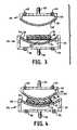
- FIG. 4is a partially schematic, side cross-sectional view of the apparatus illustrated in FIG. 2 showing the carrying out of a heating and pressing step of the method of the invention
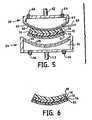
- FIG. 5is a partially schematic, side cross-sectional view of the apparatus illustrated in FIG. 2 showing a lens-removing step according to the method of the invention.
- FIG. 6is a partially schematic, side cross-sectional view of a preferred embodiment of a shaped plastic lens according to the invention having substantially no optical power.
- the present inventionis directed to shaped plastic lenses having substantially no optical power and to a method for the production of such lenses.
- reference to a lens of substantially no optical powerrefers, in general, to the absence of magnification or demagnification.
- a lenswill be considered as having substantially no optical power where the power is sufficiently low as not to be discernible or detectable by the human eye or where the power is within the limits of a published industry standard for no power lenses.
- r 1 and r 2represent the radii of curvature of the lens and n is the index of refraction.
- n ( r 1 +r 2 )( n ⁇ 1) t (II)
- the radii of curvature, (r 1 and r 2 )relate to the thickness of the lens according to the formula
- a composite laminate of a thickness of 0.100 inch (100 mils)is to be formed into a lens using a platen having a concave surface with a radius of curvature (r 1 ) of 3.514 inches (in order to form the convex side of the lens) it will be seen that the platen used to form the concave side of the lens will have a convex surface having a radius of curvature (r 2 ) of 3.481 inches.
- thickness (t)is expressed in mils.
- the power (in diopters) of lenses of different thicknesscan be calculated readily, using formula VII and examples of the power of lenses of different uniform thickness are set forth in the following TABLE I wherein focal length is expressed in meters.
- an “onion” lens having opposed convex and concave sides and uniform thicknesscan be analogized to concentric rings of an onion slice.
- Each onion ring of the same and uniform thicknessis defined by convex and concave radii. These radii have different values for each slice. The respective radii for each slice also vary with progression of the rings outwardly to the onion surface.
- Transparent plastic substrate materialsby analogy to such rings, can be molded into lenses of uniform thickness and the requirements of radii of curvature for platens can be determined readily by analogy to the geometry of an onion.
- Such lenseshowever, have optical power which, as described previously, increases with thickness.
- Plastic lenses having a convex surface of high scratch-resistant thermoplastic materialcan be produced according to the invention by using platens of different predetermined radii of curvature and thermoplastic substrate materials and shaping conditions of heat and pressure, in conjunction with forming a layer of non-uniform thickness by in situ polymerization, that negate the development of optical power and that promote instead the formation of lenses of non-uniform overall thickness and substantially no optical power.
- the particular requirements of radii of curvature and the requirements in respect of the materials and shaping conditions that permit the production of lenses of the inventionare described in detail hereinafter.
- a lens blank used to form lenses according to the inventioncan be a planar structure comprising a substantially uniformly thick layer or layers of suitable thermoplastic material(s).
- the method of the inventionwill be described farther in detail with respect to the preferred embodiment of the invention wherein the lens blank used to form lenses according to the invention is a composite structure comprising a layer of a light-polarizing material between layers of thermoplastic substrate material.
- Layer, or sheet, 12comprises a molecularly oriented light-polarizing material which provides the light-polarizing functionality of the preferred shaped lens of the invention.
- light-polarizing layer 12comprises a linear molecularly oriented dichroic material having a thickness in the range of from about 0.1 to about 3 mils (about 0.0025 to about 0.076 mm) and preferably about 0.5 mils (about 0.0125 mm).
- a preferred material for use as light-polarizing layer 12is a layer of stretched, or oriented, poly(vinyl alcohol) of about five mil thickness stained according to known methods with a dichroic dye such as iodine.
- a polarizing materialwill also preferably be borated for improved stability.
- Suitable polarizing layers of this typecan be prepared utilizing methods described in Reissue U.S. Pat. No. Re. 23,297 and in U.S. Pat. No. 4,166,871.
- Another preferred polarizing materialis a stretched poly(vinyl alcohol) sheet containing polyvinylene light-polarizing species such as may be provided by hydrochloric acid vapor processing according to known methods.
- such polarizing materialwill be borated for improved stability.
- Suitable light-polarizing materials of this typecan be prepared by the method described in U.S. Pat. No. 2,445,555. Other light-polarizing materials can, however, be employed and methods for their production can be found in U.S. Pat. Nos. 2,237,567, 2,527,400 and 2,554,850.
- one or more support, or carrier, sheetscan be employed to improve the durability and handling characteristics of the light-polarizing material.
- Support sheets of cellulose acetate, cellulose triacetate, cellulose acetate butyrate (CAB), or of other polymeric materialcan be used for this purpose.
- An adhesivecan be used to promote desired bonding without forming bubbles, haze or other visible defects. Suitable adhesives are known in the art.
- Layers 14 and 16comprise thermoplastic material, which can be molded or shaped to the desired curvature for lenses of the invention.
- Transparent thermoplastic resins known to be useful in the production of optical elementscan be used for layers 14 and 16 .
- suitable thermoplastic materialsinclude poly (methyl methacrylate), polystyrene, polycarbonate and cellulosic thermoplastic materials such as cellulose nitrate, cellulose acetate, cellulose triacetate, cellulose acetate propionate, cellulose acetate butyrate and ethyl cellulose.
- suitable materialsare those which are transparent and which exhibit good durability and moldability.
- Layers 14 and 16 of resinous materialcan be selected from the resinous materials previously mentioned, although other materials can be used. It will be apparent that the moldability or processability of the resinous materials comprising layers 14 and 16 has to be taken into consideration insofar as the required molding or lens-shaping conditions of temperature and pressure may influence the physical and optical properties of the light polarizer confined between such layers. Thus, layers 14 and 16 comprise a thermoplastic material moldable into a curved lens according to the invention without degradation or other harmful and undesirable influence on light polarizer layer 12 .
- poly (methyl methacrylate) resinsexhibit good durability, transparency and processability and the beneficial attributes and limitations of poly (methyl methacrylate) and others of the aforementioned materials, insofar as their adaptability to the production of optical elements is concerned, are known and described, for example, in U.S. Pat. Nos. 4,986,641 and 5,043,405.
- Homopolymers of methyl methacrylate and other methacrylate polymerssuch as norbornyl methacrylate can be used, as can methacrylic copolymers which include repeating units from methyl methacrylate and from other copolymerizable monomers. Examples of such homopolymers and copolymers can be found in the aforementioned U.S. Pat. Nos. 4,985,648 and 5,043,405.
- Preferred materials for layers 14 and 16are cellulose acetate butyrate and polycarbonate.
- Cellulose acetate butyrateis preferred for use in layer 14 because it has a low coefficient of stress.
- Polycarbonateis a preferred material for layer 16 because of its high impact-resistant properties.
- layer 14comprises an approximately 0.005 inch (0.127 mm) thick layer of cellulose acetate buytrate and layer 16 comprises an approximately 0.015 to 0.030 inch (0.381 to 0.762 mm) thick layer of colored polycarbonate.
- the colorationmay be provided by incorporating visible dyes in layer 16 to provide contrast and aesthetic qualities.
- the lens blankincludes an approximately 0.015 to 0.030 inch (0.381 to 0,762 mm) thick clear polycarbonate layer 18 .
- the concave surface of the lenspreferably includes a hardcoat, or a high scratch resistant layer, since polycarbonate typically scratches easily. It is preferred to utilize a clear polycarbonate layer with a hardcoat layer as layer 18 .
- Layers 14 , 16 and 18can each comprise one or more layers. Good results can be obtained using a single layer for each of respective layers 14 , 16 and 18 . Generally, it is preferred that layer 16 and optional layer 18 , when present, have a thickness greater than that of layer 14 . A differential in thickness permits light polarizing material 12 to be positioned in lens 50 (FIG. 7) more closely to the convex surface of the lens than to the concave surface. It is advantageous to have the layer of light-polarizing material 12 located as close as possible to the convex surface of the lens so that there is the least opportunity for the material through which light must pass before the light strikes the light-polarizing material to interfere with the absorption of polarized light.
- the material though which light passes before striking the light-polarizing materialshould not have any substantial birefringence.
- the employment of one or more layers of a thickness substantially greater than that of the other layerprovides a greater latitude of processing, for example, temperature and pressure, conditions which can be employed in the lens-shaping operation without detrimental influence on the physical integrity and optical properties of light-polarizer 12 .
- Optional layer 18may be the same thickness as layer 16 or may be of different thickness.
- layer 14comprises an approximately 0.005 inch (0.127 mm) thick layer of cellulose acetate butyrate
- layer 16comprises an approximately 0.015 inch (0.381 mm) thick layer of colored polycarbonate
- layer 18an approximately 0.030 inch (0.762) thick layer of clear polycarbonate having a hardcoat layer, i.e., a layer of a high scratch-resistant material, on the outer surface.
- the layers of the lens bankmay be adhered to each other by adhesives.
- Various adhesivescan be employed for this purpose, provided that they are substantially transparent and provide a haze-free lamination free of bubbles and other unacceptable and visible defects.
- the respective layers 14 , 16 and, when present, 18can, if desired, include various additives for their known and predetermined effects.
- Stabilizerssuch as ultraviolet light absorbers, antioxidants, mold-release agents, lubricating agents, surface active agents and elastomers can be present.
- Dyessuch as gray, yellow, blue or other colored dyes can also be employed to obtain a lens of a desired density or color.
- Layer 16when present, can include an abrasion-resistant layer, or coating, to improve the resistance of the concave surface of the lenses to scratching and abrasion.
- abrasion-resistant layeror coating, to improve the resistance of the concave surface of the lenses to scratching and abrasion.
- Such a layercan comprise, for example, a thermosetting, cross-linked polymeric material.
- the laminate composite structure 10 shown in FIG. 1 and from which a light-polarizing lens structure 50 such as is shown in FIG. 6 can be producedcan be produced and used in various manners.
- unitary blanks having the structure shown in FIG. 1can be formed and then molded, or shaped, to a desired lens, each blank being produced by a lamination of precut components 12 , 14 , 16 and 18 of square, round, elliptical or other shapes.
- Such blankscan be formed under heat and pressure into a lens according to the invention and the edges thereof can be ground in known manner suitable to adapt them to placement into spectacle frames.
- a composite structure of finite or endless lengthcan be formed by a continuous or semi-continuous method whereby webs or pieces of thermoplastic sheet material are adhered to the opposing sides of a light-polarizing layer. Individual blanks can then be cut from the laminate structure using a cutting apparatus such as a saw, knife, laser, etc. Such a cutting operation can be carried out at any time prior to the shaping thereof in an apparatus such as a press-forming apparatus.
- a cutting apparatussuch as a saw, knife, laser, etc.
- lens blanks of predetermined dimensions suited for the particular forming apparatus employedcan be heated and placed immediately or after substantial cooling into the forming apparatus.
- the forming processcan be by apparatus of the type shown in FIG. 2 .
- the apparatusincludes concave platen 24 , convex platen 26 , means for driving the platens into and out of pressure-applying relationship with each other and means for alternately heating and cooling the platens during each pressure-applying interval.
- Concave platen 24includes glass member 28 having smooth concave forming surface 30 , shaft 32 operatively connected to a suitable drive means, fluid chamber 33 , fluid inlet coupling 34 and fluid outlet coupling 36 .
- Convex platen 26includes glass member 38 having convex forming surface 40 , fixed support means 42 , fluid chamber 43 , fluid inlet coupling 44 and fluid outlet coupling 46 .
- the respective concave and convex forming surfaces 30 and 40have different radii of curvature which correspond substantially to the relationship expressed by formula II.
- the drive meansincludes a suitable hydraulic piston and cylinder arrangement 47 operatively connected to platen 24 for moving platen 24 into and out of pressure-applying relationship with platen 26 .
- the heating and cooling means for both the platensincludes three way valve means 49 , heating fluid conduit 51 , cooling fluid conduit 53 and fluid inlet 55 connecting one of the three way valves to each of fluid inlet couplings 34 and 44 of platens 24 and 26 respectively.
- laminated lens blank structure 22is placed in concave platen 24 so that relatively thin sheet 14 faces concave platen 24 thereby locating light polarizing layer 12 relatively near the concave platen.
- a volume of a polymerizable composition 57comprising a monomer or an oligomer and a polymerization iniatiator.
- the volume of polymerizable composition 57is determined by the requirement to obtain sufficient coverage on the surface of lens blank 22 and is a function of the lens curvature and size.
- a volume of from about 0.1 to about 0.8 ml of the polymerizable compositionis sufficient.
- polymerizable composition 57forms a layer of non-uniform thickness on the convex surface of the lens so as to provide a lens having substantially no optical power.
- Any suitable monomer or oligomer which will provide an optically clear, durable, scratch resistant, high impact-resistant polymeric film of non-uniform thickness in accordance with the method of the inventionmay be used.
- Typical suitable monomeric or oligomeric materialsinclude, for example, acrylates, methacrylates, urethanes, amines and inorganic materials such as, for example, polysiloxanes.
- the polymerizable compositionmay include a single monomer or oligomer or a mixture thereof. Any suitable polymerization initiator material may be used.
- the polymerizable compositionmay also include other additives to provide their known and predetermined effects.
- a particularly preferred polymerizable composition for use in accordance with the inventioncomprises a mixture of tetraethylene glycol methacrylate and dipentaerythritol pentacrylate monomers.
- the polymerizable compositionpreferably includes an inhibitor such as hydroquinone.
- the polymerization of the monomeric or oligomeric materialmay be carried out by any suitable polymerization technique such as free radical polymerization, cationic polymerization, ultraviolet polymerization and thermal cure polymerization. It is preferred to employ free radical polymerization.
- the concave and convex platensare then brought into pressure-applying relationship as shown in FIG. 4 to form, or shape, the laminated lens blank structure 22 , under the combined effects of heat and pressure, into a shaped structure and to form a layer of non-uniform thickness from the polymerizable composition thereby forming a shaped lens 50 (FIG. 6) having substantially no optical power.
- the layer of non-uniform thicknessis characterized by having maximum thickness in the central region of the layer thus providing a lens 50 also having maximum thickness in the central region of the lens.
- the amount of pressure applied in any particular instancewill vary with the particular nature of the lens blank structure, such as lens blank 22 , especially the nature of the thermoplastic materials in the lens blank structure and with the temperatures of the forming surfaces 30 and 40 .
- pressures in the range of from about 250 to about 800 lbs/in 2 (1724 to 5516 kilopascals) of lens areacan be suitably employed.
- a preferred pressureis about 425 lbs/in 2 (2930 kPa).
- the platensWhile pressure is applied to the laminated structure 22 , as described, the platens are heated by passing hot water through chambers 33 and 43 of platens 24 and 26 , respectively. Surfaces 30 and 40 are continually heated sufficiently to cause deformation of the polarizer layer 12 and the thermoplastic layers 14 and 16 , and layer 18 when present, and conformation of the surface of layer 16 , or layer 18 , when present, to the forming surface 40 of platen 26 as well as conformation of the surface of layer 14 to the layer of non-uniform thickness of the high-impact resistant polymeric material formed in situ according to the invention and conformation of the outer surface of the layer of non-uniform thickness to the forming surface 30 of platen 24 .
- the application of heat and pressureis sufficient to cause the deformation of the lens blank 22 such that one surface of the blank conforms to the forming surface 40 of platen 26 and the outer surface of the layer of non-uniform thickness of high-impact resistant polymeric material formed in situ according to the invention conforms to the forming surface 30 of platen 24 as well as causing the other surface of the lens blank to conform to the inner surface of the layer of non-uniform thickness.
- the method of the inventioncan be employed for the production of lenses which are relatively thick and which desirably have, therefore, the durability associated with such thickness. Lenses of widely varying thicknesses can be produced according to the invention.
- the methodis particularly suitable for the production of relatively thick lenses which, if of uniform thickness, would exhibit unacceptable optical power.
- the methodis particularly useful for the production of substantially no optical power lenses of a thickness of about 50 mils (1.27 mm) or greater, for example, in the range of from about 50 to 150 mils (1.27 to 3.81 mm).
- a platen 24having a forming surface 30 which corresponds to the predetermined curvature of the convex side of the lens to be formed. It is apparent that the convex surface of the layer 51 (FIG. 6) which is formed against forming surface 30 serves as the outer surface of the lens 50 (FIG. 6 ).
- One suitable radius of curvature for forming surface 30 for forming a convex lens surfaceis 3.514 inches.
- the radius of curvature of the opposed lens surface (and platen)can be determined for the production of a lens of any nominal thickness.
- TABLE IIshows, for various lenses which can be produced according to the method of the invention, the radii of curvature for the convex and concave forming surfaces, the center thickness, the edge thickness, the diopter and the optical power.
- the conditions of temperature and pressure sufficient to cause deformation of the lens blank and to cause polymerization of the polymerizable composition during production of lenses according to the inventioncause the finished lenses to conform to the radii of curvature of the forming surfaces of the platens.
- the requisite temperature for creating deformation of the lens blank and polymerization of the polymerizable composition to form the layer of non-uniform thicknesswill vary with the chemical composition of the poymeric materials. Using cellulose acetate butyrate and polycarbonate sheets, molding temperatures of from about 150° F. to about 200° F. A preferred molding temperature is heating at 170° F. for 70 seconds.
- the temperatures of the forming surfaces of the platenscan be controlled by the passage of heated water and cooled water, as described previously.
- the platensare preferably preheated i.e., prior to placement of the lens blank therebetween, and are heated to the requisite forming temperature for a heating cycle sufficient to form the desired shaped lens.
- the forming surfaces of the platenscan be preheated for about 20 seconds to about 170° F. in the case of cellulose acetate butyrate and polycarbonate materials prior to placing the lens blank into the mold and closing the mold for about 70 seconds during heating.
- the mold surfacesare then heated to the requisite forming temperature by the passage of heated water through the platens and the temperature is maintained for a duration, e.g., about 70 seconds, sufficient for the desired lens formation. Thereafter, the temperature of forming surfaces 30 and 40 is reduced by passage of a cooling fluid such as relatively cool water through chambers 33 and 43 of the platens. The cooling fluid is passed through the platens for a period, for example, of about 50 seconds before the press is opened.
- a cooling fluidsuch as relatively cool water
- Hot wateris supplied to the platens through conduit 51 and the relatively cool water is supplied through conduit 53 .
- valve 49opens a connecting passage between conduit 51 and inlet 55 and closes conduit 53 .
- the valve 49opens a connecting passage between conduit 53 and inlet 55 and closes conduit 51 .
- the transition from the heating cycle to the cooling cycleis carried out by operating valve 49 to mix cool water with the hot water until the hot water is completely displaced by cool water. Transition from the cooling cycle to the heating cycle is carried out by reversing the operation.
- platens 24 and 26are separated to relieve the pressure on the shaped lens and permit its removal, as shown in FIG. 5 .
- the shaped lensmay adhere to one of the forming surfaces in which case it may be removed by a stream of compressed air supplied by air nozzle 48 .
- FIG. 6illustrates a shaped light-polarizing lens 50 , concave on the side formed by convex platen 26 and convex on the side formed by concave platen 24 .
- layer 51 of non-uniform thicknesswhich has high scratch resistance and which forms the convex surface of the lens 50 .
- shaped lenses of substantially no optical powerwhich have a convex surface of a high scratch-resistant and high impact-resistant material can be advantageously provided. It will be appreciated, however, that other apparatus can be used and variations in process conditions, such as heating and cooling cycles, may be employed, depending upon the particular materials present in the lens blank and the polymerizable composition.
Landscapes
- Engineering & Computer Science (AREA)
- Mechanical Engineering (AREA)
- Health & Medical Sciences (AREA)
- Manufacturing & Machinery (AREA)
- Ophthalmology & Optometry (AREA)
- Casting Or Compression Moulding Of Plastics Or The Like (AREA)
- Eyeglasses (AREA)
Abstract
Description


| TABLE I | ||
| t(mils) | P (diopters) | |
| 30 | −0.0366 | −27.3 |
| 45 | −0.0549 | −18.2 |
| 60 | −0.0732 | −13.66 |
| 75 | −0.0915 | −10.93 |
| 90 | −0.1098 | −9.11 |
| 100 | −0.1220 | −8.20 |
| TABLE II | |||||
| Convex | Concave | Center | Edge | Optical | |
| Radii | Radii | Thickness | Thickness* | Power | |
| (inch) | (inch) | (inch) | (inch) | Diopter | (diopter) |
| 3.514 | 3.494 | 0.060 | 0.057 | 6 | −0.001 |
| 3.514 | 3.486 | 0.075 | 0.071 | 6 | −0.001 |
| 2.633 | 2.613 | 0.060 | 0.053 | 8 | −0.001 |
| 2.633 | 2.605 | 0.075 | 0.067 | 8 | −0.001 |
| *Edge is 1.5” from the center of the lens. | |||||
Claims (6)

Priority Applications (7)
| Application Number | Priority Date | Filing Date | Title |
|---|---|---|---|
| US09/966,179US6746631B2 (en) | 2001-09-28 | 2001-09-28 | Shaped plastic lenses and method for making the same |
| PCT/US2002/030653WO2003028987A2 (en) | 2001-09-28 | 2002-09-26 | Shaped plastic lenses and method for making the same |
| EP02778367AEP1429913B1 (en) | 2001-09-28 | 2002-09-26 | Shaped plastic lenses and method for making the same |
| JP2003532279AJP2005504999A (en) | 2001-09-28 | 2002-09-26 | Molded plastic lens and manufacturing method thereof |
| AT02778367TATE355962T1 (en) | 2001-09-28 | 2002-09-26 | DEFORMED PLASTIC LENS AND METHOD FOR PRODUCING THE SAME |
| DE60218709TDE60218709T2 (en) | 2001-09-28 | 2002-09-26 | PLASTIC MOLDED LENS AND METHOD FOR THE PRODUCTION THEREOF |
| US10/805,759US7042641B2 (en) | 2001-09-28 | 2004-03-22 | Shaped plastic lenses and method for making the same |
Applications Claiming Priority (1)
| Application Number | Priority Date | Filing Date | Title |
|---|---|---|---|
| US09/966,179US6746631B2 (en) | 2001-09-28 | 2001-09-28 | Shaped plastic lenses and method for making the same |
Related Child Applications (1)
| Application Number | Title | Priority Date | Filing Date |
|---|---|---|---|
| US10/805,759DivisionUS7042641B2 (en) | 2001-09-28 | 2004-03-22 | Shaped plastic lenses and method for making the same |
Publications (2)
| Publication Number | Publication Date |
|---|---|
| US20030071965A1 US20030071965A1 (en) | 2003-04-17 |
| US6746631B2true US6746631B2 (en) | 2004-06-08 |
Family
ID=25511019
Family Applications (2)
| Application Number | Title | Priority Date | Filing Date |
|---|---|---|---|
| US09/966,179Expired - LifetimeUS6746631B2 (en) | 2001-09-28 | 2001-09-28 | Shaped plastic lenses and method for making the same |
| US10/805,759Expired - LifetimeUS7042641B2 (en) | 2001-09-28 | 2004-03-22 | Shaped plastic lenses and method for making the same |
Family Applications After (1)
| Application Number | Title | Priority Date | Filing Date |
|---|---|---|---|
| US10/805,759Expired - LifetimeUS7042641B2 (en) | 2001-09-28 | 2004-03-22 | Shaped plastic lenses and method for making the same |
Country Status (6)
| Country | Link |
|---|---|
| US (2) | US6746631B2 (en) |
| EP (1) | EP1429913B1 (en) |
| JP (1) | JP2005504999A (en) |
| AT (1) | ATE355962T1 (en) |
| DE (1) | DE60218709T2 (en) |
| WO (1) | WO2003028987A2 (en) |
Cited By (3)
| Publication number | Priority date | Publication date | Assignee | Title |
|---|---|---|---|---|
| WO2008106389A1 (en)* | 2007-02-26 | 2008-09-04 | 3Form, Inc. | Formable fused polymer panels containing light refracting films |
| US20110199680A1 (en)* | 2010-01-22 | 2011-08-18 | Oakley, Inc. | Eyewear with three-dimensional viewing capability |
| US20110205626A1 (en)* | 2010-01-22 | 2011-08-25 | Oakley, Inc. | Lenses for 3d eyewear |
Families Citing this family (10)
| Publication number | Priority date | Publication date | Assignee | Title |
|---|---|---|---|---|
| US7128415B2 (en)* | 2003-04-30 | 2006-10-31 | Polylite Taiwan Company, Ltd | Method of forming polarized or photochromic lenses by fusing polycarbonate with other plastic materials |
| US8183033B2 (en)* | 2007-03-23 | 2012-05-22 | Bioinnovations Oy | Methods for preparing and performing analyses |
| US7775659B2 (en)* | 2007-04-13 | 2010-08-17 | Nesty Gary W | Sunglass lens |
| US7784939B2 (en)* | 2008-04-15 | 2010-08-31 | Ohkei Optical Co., Ltd. | Polarizing lens for sunglasses and method of shaping the same |
| EP2697049B1 (en)* | 2011-04-15 | 2023-07-12 | Safilo S.P.A. | Method of forming curved lenses |
| US9370883B2 (en) | 2011-04-15 | 2016-06-21 | Polaroid Eyewear, Ltd. | Curved lenses and related methods |
| EP2699953B1 (en) | 2011-04-15 | 2019-03-27 | Safilo S.P.A. | Curved lenses and related methods |
| KR101672104B1 (en)* | 2011-08-02 | 2016-11-03 | 쓰리엠 이노베이티브 프로퍼티즈 캄파니 | Graphic article |
| CN103732416B (en) | 2011-08-02 | 2018-01-26 | 3M创新有限公司 | Graphics |
| CN114859444B (en)* | 2022-05-06 | 2024-03-19 | 西安交通大学 | A method for preparing chalcogenide glass infrared compound eyes |
Citations (12)
| Publication number | Priority date | Publication date | Assignee | Title |
|---|---|---|---|---|
| US2237567A (en) | 1939-05-04 | 1941-04-08 | Polaroid Corp | Light polarizer and process of manufacturing the same |
| US2445555A (en) | 1945-04-16 | 1948-07-20 | Polaroid Corp | Light-polarizing polyvinyl sheet containing polyvinyl compoundboric acid complex |
| US2527400A (en) | 1947-07-16 | 1950-10-24 | Polaroid Corp | Melamine-formaldehyde-surfaced cellulose derivative lamination for polarizers |
| USRE23297E (en) | 1950-11-28 | Sheetlike light-polarizing complex | ||
| US2554850A (en) | 1948-06-18 | 1951-05-29 | Polaroid Corp | Heat resistant light-polarizing polyvinyl borate film containing borax |
| US3940304A (en) | 1972-05-02 | 1976-02-24 | Polaroid Corporation | Method of making composite light-polarizing element |
| US4166871A (en) | 1977-06-29 | 1979-09-04 | Polaroid Corporation | Iodine stained light polarizer |
| US4985648A (en) | 1988-07-26 | 1991-01-15 | Matsushita Electric Industrial Co. Ltd. | Switching output circuit with high speed operation and low power consumption |
| US4986641A (en) | 1989-05-19 | 1991-01-22 | U.S. Philips Corp. | Retrofocus objective lens and optical scanning device provided with such a lens |
| US5043405A (en) | 1988-01-07 | 1991-08-27 | Asahi Kasei Kogyo Kabushiki Kaisha | Methacrylic copolymer having low moisture absorption properties |
| US5434707A (en) | 1993-09-14 | 1995-07-18 | Polaroid Corporation | Shaped plastic light-polarizing lens and method of making same |
| US6319433B1 (en)* | 1999-09-14 | 2001-11-20 | Invicta Corporation | Composite ophthalmic lens remolding system for forming a lens therein |
Family Cites Families (4)
| Publication number | Priority date | Publication date | Assignee | Title |
|---|---|---|---|---|
| US23297A (en)* | 1859-03-22 | Filtee | ||
| US3560076A (en)* | 1967-06-01 | 1971-02-02 | Polaroid Corp | Curved laminated light polarizing device |
| US5751481A (en)* | 1996-04-05 | 1998-05-12 | Polaroid Corporation | Laminar light-polarizing lens blank for producing prescription lens |
| JP2002192554A (en)* | 2000-12-22 | 2002-07-10 | Yasunobu Nakakoshi | Method for molding and manufacturing polyurethane polarizing lens |
- 2001
- 2001-09-28USUS09/966,179patent/US6746631B2/ennot_activeExpired - Lifetime
- 2002
- 2002-09-26DEDE60218709Tpatent/DE60218709T2/ennot_activeExpired - Lifetime
- 2002-09-26JPJP2003532279Apatent/JP2005504999A/enactivePending
- 2002-09-26WOPCT/US2002/030653patent/WO2003028987A2/enactiveIP Right Grant
- 2002-09-26ATAT02778367Tpatent/ATE355962T1/ennot_activeIP Right Cessation
- 2002-09-26EPEP02778367Apatent/EP1429913B1/ennot_activeExpired - Lifetime
- 2004
- 2004-03-22USUS10/805,759patent/US7042641B2/ennot_activeExpired - Lifetime
Patent Citations (12)
| Publication number | Priority date | Publication date | Assignee | Title |
|---|---|---|---|---|
| USRE23297E (en) | 1950-11-28 | Sheetlike light-polarizing complex | ||
| US2237567A (en) | 1939-05-04 | 1941-04-08 | Polaroid Corp | Light polarizer and process of manufacturing the same |
| US2445555A (en) | 1945-04-16 | 1948-07-20 | Polaroid Corp | Light-polarizing polyvinyl sheet containing polyvinyl compoundboric acid complex |
| US2527400A (en) | 1947-07-16 | 1950-10-24 | Polaroid Corp | Melamine-formaldehyde-surfaced cellulose derivative lamination for polarizers |
| US2554850A (en) | 1948-06-18 | 1951-05-29 | Polaroid Corp | Heat resistant light-polarizing polyvinyl borate film containing borax |
| US3940304A (en) | 1972-05-02 | 1976-02-24 | Polaroid Corporation | Method of making composite light-polarizing element |
| US4166871A (en) | 1977-06-29 | 1979-09-04 | Polaroid Corporation | Iodine stained light polarizer |
| US5043405A (en) | 1988-01-07 | 1991-08-27 | Asahi Kasei Kogyo Kabushiki Kaisha | Methacrylic copolymer having low moisture absorption properties |
| US4985648A (en) | 1988-07-26 | 1991-01-15 | Matsushita Electric Industrial Co. Ltd. | Switching output circuit with high speed operation and low power consumption |
| US4986641A (en) | 1989-05-19 | 1991-01-22 | U.S. Philips Corp. | Retrofocus objective lens and optical scanning device provided with such a lens |
| US5434707A (en) | 1993-09-14 | 1995-07-18 | Polaroid Corporation | Shaped plastic light-polarizing lens and method of making same |
| US6319433B1 (en)* | 1999-09-14 | 2001-11-20 | Invicta Corporation | Composite ophthalmic lens remolding system for forming a lens therein |
Cited By (8)
| Publication number | Priority date | Publication date | Assignee | Title |
|---|---|---|---|---|
| WO2008106389A1 (en)* | 2007-02-26 | 2008-09-04 | 3Form, Inc. | Formable fused polymer panels containing light refracting films |
| US20100265581A1 (en)* | 2007-02-26 | 2010-10-21 | 3Form | Formable fused polymer panels containing light refracting films |
| US7940459B2 (en)* | 2007-02-26 | 2011-05-10 | 3Form, Inc. | Formable fused polymer panels containing light refracting films |
| CN101657751B (en)* | 2007-02-26 | 2012-11-14 | 亨特道格拉斯工业瑞士有限责任公司 | Formable fused polymer panels containing light refracting films |
| USRE45978E1 (en)* | 2007-02-26 | 2016-04-19 | 3Form, Llc | Formable fused polymer panels containing light refracting films |
| US20110199680A1 (en)* | 2010-01-22 | 2011-08-18 | Oakley, Inc. | Eyewear with three-dimensional viewing capability |
| US20110205626A1 (en)* | 2010-01-22 | 2011-08-25 | Oakley, Inc. | Lenses for 3d eyewear |
| US8547635B2 (en) | 2010-01-22 | 2013-10-01 | Oakley, Inc. | Lenses for 3D eyewear |
Also Published As
| Publication number | Publication date |
|---|---|
| EP1429913B1 (en) | 2007-03-07 |
| US20040227995A1 (en) | 2004-11-18 |
| JP2005504999A (en) | 2005-02-17 |
| DE60218709T2 (en) | 2008-03-06 |
| EP1429913A2 (en) | 2004-06-23 |
| WO2003028987A2 (en) | 2003-04-10 |
| DE60218709D1 (en) | 2007-04-19 |
| US7042641B2 (en) | 2006-05-09 |
| WO2003028987A3 (en) | 2003-08-14 |
| US20030071965A1 (en) | 2003-04-17 |
| ATE355962T1 (en) | 2007-03-15 |
Similar Documents
| Publication | Publication Date | Title |
|---|---|---|
| US5434707A (en) | Shaped plastic light-polarizing lens and method of making same | |
| US5805336A (en) | Optical lens blank with polarizer aligned between plastic birefringent sheets | |
| US5751481A (en) | Laminar light-polarizing lens blank for producing prescription lens | |
| US6801360B2 (en) | Polarized lens formed by injection/coining injection molding process | |
| US6746631B2 (en) | Shaped plastic lenses and method for making the same | |
| US6177032B1 (en) | Polarized ophthalmic lenses and methods for making same | |
| US7311399B2 (en) | Method of making a thermoplastic-based article and a thermoplastic-based article made thereby | |
| US6786599B2 (en) | Polarized lens of plastic lamination and the production method of the same | |
| KR20020033091A (en) | Transparent optical product | |
| JP2009139964A5 (en) | ||
| JP2005504999A5 (en) | ||
| CA2031573C (en) | Method for forming plastic optical quality spectacle lenses | |
| EP2697049B1 (en) | Method of forming curved lenses | |
| US20040080062A1 (en) | Processes for forming a polarized lens via injection/coining injection molding | |
| EP0457855A1 (en) | Method for forming plastic optical quality spectacle | |
| JP2010054950A (en) | Functional intermediate sheet and method for manufacturing polarizing lens applying functional intermediate sheet | |
| JP2010039454A (en) | Functional intermediate sheet |
Legal Events
| Date | Code | Title | Description |
|---|---|---|---|
| AS | Assignment | Owner name:POLAROID CORPORATION, MASSACHUSETTS Free format text:ASSIGNMENT OF ASSIGNORS INTEREST;ASSIGNOR:GETTENS, NANCY J.;REEL/FRAME:012221/0496 Effective date:20010928 | |
| STCF | Information on status: patent grant | Free format text:PATENTED CASE | |
| AS | Assignment | Owner name:OEP IMAGINIG OPERATING CORPORATION, NEW YORK Free format text:ASSIGNMENT OF ASSIGNORS INTEREST;ASSIGNOR:POLAROID CORPORATION;REEL/FRAME:016427/0144 Effective date:20020731 Owner name:POLAROID CORPORATION, NEW YORK Free format text:CHANGE OF NAME;ASSIGNOR:OEP IMAGING OPERATING CORPORATION;REEL/FRAME:016470/0006 Effective date:20020801 Owner name:OEP IMAGINIG OPERATING CORPORATION,NEW YORK Free format text:ASSIGNMENT OF ASSIGNORS INTEREST;ASSIGNOR:POLAROID CORPORATION;REEL/FRAME:016427/0144 Effective date:20020731 Owner name:POLAROID CORPORATION,NEW YORK Free format text:CHANGE OF NAME;ASSIGNOR:OEP IMAGING OPERATING CORPORATION;REEL/FRAME:016470/0006 Effective date:20020801 | |
| AS | Assignment | Owner name:WILMINGTON TRUST COMPANY, AS COLLATERAL AGENT, DEL Free format text:ASSIGNMENT OF ASSIGNORS INTEREST;ASSIGNORS:POLAROLD HOLDING COMPANY;POLAROID CORPORATION;POLAROID ASIA PACIFIC LLC;AND OTHERS;REEL/FRAME:016602/0332 Effective date:20050428 Owner name:JPMORGAN CHASE BANK,N.A,AS ADMINISTRATIVE AGENT, W Free format text:SECURITY INTEREST;ASSIGNORS:POLAROID HOLDING COMPANY;POLAROID CORPORATION;POLAROID ASIA PACIFIC LLC;AND OTHERS;REEL/FRAME:016602/0603 Effective date:20050428 Owner name:WILMINGTON TRUST COMPANY, AS COLLATERAL AGENT,DELA Free format text:SECURITY AGREEMENT;ASSIGNORS:POLAROLD HOLDING COMPANY;POLAROID CORPORATION;POLAROID ASIA PACIFIC LLC;AND OTHERS;REEL/FRAME:016602/0332 Effective date:20050428 Owner name:JPMORGAN CHASE BANK,N.A,AS ADMINISTRATIVE AGENT,WI Free format text:SECURITY INTEREST;ASSIGNORS:POLAROID HOLDING COMPANY;POLAROID CORPORATION;POLAROID ASIA PACIFIC LLC;AND OTHERS;REEL/FRAME:016602/0603 Effective date:20050428 Owner name:WILMINGTON TRUST COMPANY, AS COLLATERAL AGENT, DEL Free format text:SECURITY AGREEMENT;ASSIGNORS:POLAROLD HOLDING COMPANY;POLAROID CORPORATION;POLAROID ASIA PACIFIC LLC;AND OTHERS;REEL/FRAME:016602/0332 Effective date:20050428 | |
| AS | Assignment | Owner name:OEP IMAGING OPERATING CORPORATION,NEW YORK Free format text:ASSIGNMENT OF ASSIGNORS INTEREST;ASSIGNOR:POLAROID CORPORATION;REEL/FRAME:018584/0600 Effective date:20020731 Owner name:OEP IMAGING OPERATING CORPORATION, NEW YORK Free format text:ASSIGNMENT OF ASSIGNORS INTEREST;ASSIGNOR:POLAROID CORPORATION;REEL/FRAME:018584/0600 Effective date:20020731 | |
| AS | Assignment | Owner name:POLAROID CORPORATION (FMR OEP IMAGING OPERATING CO Free format text:SUPPLEMENTAL ASSIGNMENT OF PATENTS;ASSIGNOR:PRIMARY PDC, INC. (FMR POLAROID CORPORATION);REEL/FRAME:019077/0001 Effective date:20070122 | |
| AS | Assignment | Owner name:POLAROID HOLDING COMPANY, MASSACHUSETTS Free format text:RELEASE OF SECURITY INTEREST IN PATENTS;ASSIGNOR:WILMINGTON TRUST COMPANY;REEL/FRAME:019699/0512 Effective date:20070425 Owner name:POLAROID CORPORATION, MASSACHUSETTS Free format text:RELEASE OF SECURITY INTEREST IN PATENTS;ASSIGNOR:WILMINGTON TRUST COMPANY;REEL/FRAME:019699/0512 Effective date:20070425 Owner name:POLAROID CAPITAL LLC, MASSACHUSETTS Free format text:RELEASE OF SECURITY INTEREST IN PATENTS;ASSIGNOR:WILMINGTON TRUST COMPANY;REEL/FRAME:019699/0512 Effective date:20070425 Owner name:POLAROID ASIA PACIFIC LLC, MASSACHUSETTS Free format text:RELEASE OF SECURITY INTEREST IN PATENTS;ASSIGNOR:WILMINGTON TRUST COMPANY;REEL/FRAME:019699/0512 Effective date:20070425 Owner name:POLAROID EYEWEAR LLC, MASSACHUSETTS Free format text:RELEASE OF SECURITY INTEREST IN PATENTS;ASSIGNOR:WILMINGTON TRUST COMPANY;REEL/FRAME:019699/0512 Effective date:20070425 Owner name:POLOROID INTERNATIONAL HOLDING LLC, MASSACHUSETTS Free format text:RELEASE OF SECURITY INTEREST IN PATENTS;ASSIGNOR:WILMINGTON TRUST COMPANY;REEL/FRAME:019699/0512 Effective date:20070425 Owner name:POLAROID INVESTMENT LLC, MASSACHUSETTS Free format text:RELEASE OF SECURITY INTEREST IN PATENTS;ASSIGNOR:WILMINGTON TRUST COMPANY;REEL/FRAME:019699/0512 Effective date:20070425 Owner name:POLAROID LATIN AMERICA I CORPORATION, MASSACHUSETT Free format text:RELEASE OF SECURITY INTEREST IN PATENTS;ASSIGNOR:WILMINGTON TRUST COMPANY;REEL/FRAME:019699/0512 Effective date:20070425 Owner name:POLAROID NEW BEDFORD REAL ESTATE LLC, MASSACHUSETT Free format text:RELEASE OF SECURITY INTEREST IN PATENTS;ASSIGNOR:WILMINGTON TRUST COMPANY;REEL/FRAME:019699/0512 Effective date:20070425 Owner name:POLAROID NORWOOD REAL ESTATE LLC, MASSACHUSETTS Free format text:RELEASE OF SECURITY INTEREST IN PATENTS;ASSIGNOR:WILMINGTON TRUST COMPANY;REEL/FRAME:019699/0512 Effective date:20070425 Owner name:POLAROID WALTHAM REAL ESTATE LLC, MASSACHUSETTS Free format text:RELEASE OF SECURITY INTEREST IN PATENTS;ASSIGNOR:WILMINGTON TRUST COMPANY;REEL/FRAME:019699/0512 Effective date:20070425 Owner name:PETTERS CONSUMER BRANDS, LLC, MASSACHUSETTS Free format text:RELEASE OF SECURITY INTEREST IN PATENTS;ASSIGNOR:WILMINGTON TRUST COMPANY;REEL/FRAME:019699/0512 Effective date:20070425 Owner name:PETTERS CONSUMER BRANDS INTERNATIONAL, LLC, MASSAC Free format text:RELEASE OF SECURITY INTEREST IN PATENTS;ASSIGNOR:WILMINGTON TRUST COMPANY;REEL/FRAME:019699/0512 Effective date:20070425 Owner name:ZINK INCORPORATED, MASSACHUSETTS Free format text:RELEASE OF SECURITY INTEREST IN PATENTS;ASSIGNOR:WILMINGTON TRUST COMPANY;REEL/FRAME:019699/0512 Effective date:20070425 Owner name:POLAROID HOLDING COMPANY,MASSACHUSETTS Free format text:RELEASE OF SECURITY INTEREST IN PATENTS;ASSIGNOR:WILMINGTON TRUST COMPANY;REEL/FRAME:019699/0512 Effective date:20070425 Owner name:POLAROID CORPORATION,MASSACHUSETTS Free format text:RELEASE OF SECURITY INTEREST IN PATENTS;ASSIGNOR:WILMINGTON TRUST COMPANY;REEL/FRAME:019699/0512 Effective date:20070425 Owner name:POLAROID CAPITAL LLC,MASSACHUSETTS Free format text:RELEASE OF SECURITY INTEREST IN PATENTS;ASSIGNOR:WILMINGTON TRUST COMPANY;REEL/FRAME:019699/0512 Effective date:20070425 Owner name:POLAROID ASIA PACIFIC LLC,MASSACHUSETTS Free format text:RELEASE OF SECURITY INTEREST IN PATENTS;ASSIGNOR:WILMINGTON TRUST COMPANY;REEL/FRAME:019699/0512 Effective date:20070425 Owner name:POLAROID EYEWEAR LLC,MASSACHUSETTS Free format text:RELEASE OF SECURITY INTEREST IN PATENTS;ASSIGNOR:WILMINGTON TRUST COMPANY;REEL/FRAME:019699/0512 Effective date:20070425 Owner name:POLOROID INTERNATIONAL HOLDING LLC,MASSACHUSETTS Free format text:RELEASE OF SECURITY INTEREST IN PATENTS;ASSIGNOR:WILMINGTON TRUST COMPANY;REEL/FRAME:019699/0512 Effective date:20070425 Owner name:POLAROID INVESTMENT LLC,MASSACHUSETTS Free format text:RELEASE OF SECURITY INTEREST IN PATENTS;ASSIGNOR:WILMINGTON TRUST COMPANY;REEL/FRAME:019699/0512 Effective date:20070425 Owner name:POLAROID LATIN AMERICA I CORPORATION,MASSACHUSETTS Free format text:RELEASE OF SECURITY INTEREST IN PATENTS;ASSIGNOR:WILMINGTON TRUST COMPANY;REEL/FRAME:019699/0512 Effective date:20070425 Owner name:POLAROID NEW BEDFORD REAL ESTATE LLC,MASSACHUSETTS Free format text:RELEASE OF SECURITY INTEREST IN PATENTS;ASSIGNOR:WILMINGTON TRUST COMPANY;REEL/FRAME:019699/0512 Effective date:20070425 Owner name:POLAROID NORWOOD REAL ESTATE LLC,MASSACHUSETTS Free format text:RELEASE OF SECURITY INTEREST IN PATENTS;ASSIGNOR:WILMINGTON TRUST COMPANY;REEL/FRAME:019699/0512 Effective date:20070425 Owner name:POLAROID WALTHAM REAL ESTATE LLC,MASSACHUSETTS Free format text:RELEASE OF SECURITY INTEREST IN PATENTS;ASSIGNOR:WILMINGTON TRUST COMPANY;REEL/FRAME:019699/0512 Effective date:20070425 Owner name:PETTERS CONSUMER BRANDS, LLC,MASSACHUSETTS Free format text:RELEASE OF SECURITY INTEREST IN PATENTS;ASSIGNOR:WILMINGTON TRUST COMPANY;REEL/FRAME:019699/0512 Effective date:20070425 Owner name:PETTERS CONSUMER BRANDS INTERNATIONAL, LLC,MASSACH Free format text:RELEASE OF SECURITY INTEREST IN PATENTS;ASSIGNOR:WILMINGTON TRUST COMPANY;REEL/FRAME:019699/0512 Effective date:20070425 Owner name:ZINK INCORPORATED,MASSACHUSETTS Free format text:RELEASE OF SECURITY INTEREST IN PATENTS;ASSIGNOR:WILMINGTON TRUST COMPANY;REEL/FRAME:019699/0512 Effective date:20070425 | |
| FEPP | Fee payment procedure | Free format text:PAYOR NUMBER ASSIGNED (ORIGINAL EVENT CODE: ASPN); ENTITY STATUS OF PATENT OWNER: LARGE ENTITY Free format text:PAYER NUMBER DE-ASSIGNED (ORIGINAL EVENT CODE: RMPN); ENTITY STATUS OF PATENT OWNER: LARGE ENTITY | |
| REMI | Maintenance fee reminder mailed | ||
| AS | Assignment | Owner name:STYLEMARK, INC., FLORIDA Free format text:ASSIGNMENT OF ASSIGNORS INTEREST;ASSIGNOR:POLAROID CORPORATION;REEL/FRAME:020690/0567 Effective date:20070305 Owner name:POLAROID HOLDING COMPANY, MASSACHUSETTS Free format text:RELEASE OF SECURITY INTEREST IN PATENTS;ASSIGNOR:JPMORGAN CHASE BANK, N.A.;REEL/FRAME:020733/0001 Effective date:20080225 Owner name:POLAROID INTERNATIONAL HOLDING LLC, MASSACHUSETTS Free format text:RELEASE OF SECURITY INTEREST IN PATENTS;ASSIGNOR:JPMORGAN CHASE BANK, N.A.;REEL/FRAME:020733/0001 Effective date:20080225 Owner name:POLAROID INVESTMENT LLC, MASSACHUSETTS Free format text:RELEASE OF SECURITY INTEREST IN PATENTS;ASSIGNOR:JPMORGAN CHASE BANK, N.A.;REEL/FRAME:020733/0001 Effective date:20080225 Owner name:POLAROID LATIN AMERICA I CORPORATION, MASSACHUSETT Free format text:RELEASE OF SECURITY INTEREST IN PATENTS;ASSIGNOR:JPMORGAN CHASE BANK, N.A.;REEL/FRAME:020733/0001 Effective date:20080225 Owner name:POLAROID NEW BEDFORD REAL ESTATE LLC, MASSACHUSETT Free format text:RELEASE OF SECURITY INTEREST IN PATENTS;ASSIGNOR:JPMORGAN CHASE BANK, N.A.;REEL/FRAME:020733/0001 Effective date:20080225 Owner name:POLAROID NORWOOD REAL ESTATE LLC, MASSACHUSETTS Free format text:RELEASE OF SECURITY INTEREST IN PATENTS;ASSIGNOR:JPMORGAN CHASE BANK, N.A.;REEL/FRAME:020733/0001 Effective date:20080225 Owner name:POLAROID WALTHAM REAL ESTATE LLC, MASSACHUSETTS Free format text:RELEASE OF SECURITY INTEREST IN PATENTS;ASSIGNOR:JPMORGAN CHASE BANK, N.A.;REEL/FRAME:020733/0001 Effective date:20080225 Owner name:POLAROID CONSUMER ELECTRONICS, LLC, (FORMERLY KNOW Free format text:RELEASE OF SECURITY INTEREST IN PATENTS;ASSIGNOR:JPMORGAN CHASE BANK, N.A.;REEL/FRAME:020733/0001 Effective date:20080225 Owner name:POLAROID CONSUMER ELECTRONICS INTERNATIONAL, LLC, Free format text:RELEASE OF SECURITY INTEREST IN PATENTS;ASSIGNOR:JPMORGAN CHASE BANK, N.A.;REEL/FRAME:020733/0001 Effective date:20080225 Owner name:ZINK INCORPORATED, MASSACHUSETTS Free format text:RELEASE OF SECURITY INTEREST IN PATENTS;ASSIGNOR:JPMORGAN CHASE BANK, N.A.;REEL/FRAME:020733/0001 Effective date:20080225 Owner name:POLAROID CORPORATION, MASSACHUSETTS Free format text:RELEASE OF SECURITY INTEREST IN PATENTS;ASSIGNOR:JPMORGAN CHASE BANK, N.A.;REEL/FRAME:020733/0001 Effective date:20080225 Owner name:POLAROID ASIA PACIFIC LLC, MASSACHUSETTS Free format text:RELEASE OF SECURITY INTEREST IN PATENTS;ASSIGNOR:JPMORGAN CHASE BANK, N.A.;REEL/FRAME:020733/0001 Effective date:20080225 Owner name:POLAROID CAPITAL LLC, MASSACHUSETTS Free format text:RELEASE OF SECURITY INTEREST IN PATENTS;ASSIGNOR:JPMORGAN CHASE BANK, N.A.;REEL/FRAME:020733/0001 Effective date:20080225 Owner name:PLLAROID EYEWEAR I LLC, MASSACHUSETTS Free format text:RELEASE OF SECURITY INTEREST IN PATENTS;ASSIGNOR:JPMORGAN CHASE BANK, N.A.;REEL/FRAME:020733/0001 Effective date:20080225 Owner name:POLAROID HOLDING COMPANY,MASSACHUSETTS Free format text:RELEASE OF SECURITY INTEREST IN PATENTS;ASSIGNOR:JPMORGAN CHASE BANK, N.A.;REEL/FRAME:020733/0001 Effective date:20080225 Owner name:POLAROID INTERNATIONAL HOLDING LLC,MASSACHUSETTS Free format text:RELEASE OF SECURITY INTEREST IN PATENTS;ASSIGNOR:JPMORGAN CHASE BANK, N.A.;REEL/FRAME:020733/0001 Effective date:20080225 Owner name:POLAROID INVESTMENT LLC,MASSACHUSETTS Free format text:RELEASE OF SECURITY INTEREST IN PATENTS;ASSIGNOR:JPMORGAN CHASE BANK, N.A.;REEL/FRAME:020733/0001 Effective date:20080225 Owner name:POLAROID LATIN AMERICA I CORPORATION,MASSACHUSETTS Free format text:RELEASE OF SECURITY INTEREST IN PATENTS;ASSIGNOR:JPMORGAN CHASE BANK, N.A.;REEL/FRAME:020733/0001 Effective date:20080225 Owner name:POLAROID NEW BEDFORD REAL ESTATE LLC,MASSACHUSETTS Free format text:RELEASE OF SECURITY INTEREST IN PATENTS;ASSIGNOR:JPMORGAN CHASE BANK, N.A.;REEL/FRAME:020733/0001 Effective date:20080225 Owner name:POLAROID NORWOOD REAL ESTATE LLC,MASSACHUSETTS Free format text:RELEASE OF SECURITY INTEREST IN PATENTS;ASSIGNOR:JPMORGAN CHASE BANK, N.A.;REEL/FRAME:020733/0001 Effective date:20080225 Owner name:POLAROID WALTHAM REAL ESTATE LLC,MASSACHUSETTS Free format text:RELEASE OF SECURITY INTEREST IN PATENTS;ASSIGNOR:JPMORGAN CHASE BANK, N.A.;REEL/FRAME:020733/0001 Effective date:20080225 Owner name:ZINK INCORPORATED,MASSACHUSETTS Free format text:RELEASE OF SECURITY INTEREST IN PATENTS;ASSIGNOR:JPMORGAN CHASE BANK, N.A.;REEL/FRAME:020733/0001 Effective date:20080225 Owner name:POLAROID CORPORATION,MASSACHUSETTS Free format text:RELEASE OF SECURITY INTEREST IN PATENTS;ASSIGNOR:JPMORGAN CHASE BANK, N.A.;REEL/FRAME:020733/0001 Effective date:20080225 Owner name:POLAROID ASIA PACIFIC LLC,MASSACHUSETTS Free format text:RELEASE OF SECURITY INTEREST IN PATENTS;ASSIGNOR:JPMORGAN CHASE BANK, N.A.;REEL/FRAME:020733/0001 Effective date:20080225 Owner name:POLAROID CAPITAL LLC,MASSACHUSETTS Free format text:RELEASE OF SECURITY INTEREST IN PATENTS;ASSIGNOR:JPMORGAN CHASE BANK, N.A.;REEL/FRAME:020733/0001 Effective date:20080225 Owner name:PLLAROID EYEWEAR I LLC,MASSACHUSETTS Free format text:RELEASE OF SECURITY INTEREST IN PATENTS;ASSIGNOR:JPMORGAN CHASE BANK, N.A.;REEL/FRAME:020733/0001 Effective date:20080225 | |
| FPAY | Fee payment | Year of fee payment:4 | |
| SULP | Surcharge for late payment | ||
| FPAY | Fee payment | Year of fee payment:8 | |
| AS | Assignment | Owner name:POLAROID EYEWEAR U.S., LLC, FLORIDA Free format text:ASSIGNMENT OF ASSIGNORS INTEREST;ASSIGNOR:STYLEMARK LLC;REEL/FRAME:027378/0355 Effective date:20111213 | |
| FEPP | Fee payment procedure | Free format text:PAYOR NUMBER ASSIGNED (ORIGINAL EVENT CODE: ASPN); ENTITY STATUS OF PATENT OWNER: LARGE ENTITY Free format text:PAYER NUMBER DE-ASSIGNED (ORIGINAL EVENT CODE: RMPN); ENTITY STATUS OF PATENT OWNER: LARGE ENTITY | |
| AS | Assignment | Owner name:SAFILO USA, INC., NEW JERSEY Free format text:MERGER;ASSIGNOR:POLAROID EYEWEAR U.S., LLC;REEL/FRAME:032862/0884 Effective date:20121217 | |
| FPAY | Fee payment | Year of fee payment:12 | |
| AS | Assignment | Owner name:SAFILO S.P.A., ITALY Free format text:ASSIGNMENT OF ASSIGNORS INTEREST;ASSIGNOR:SAFILO USA, INC.;REEL/FRAME:041329/0474 Effective date:20170210 |