US6746401B2 - Tissue ablation visualization - Google Patents
Tissue ablation visualizationDownload PDFInfo
- Publication number
- US6746401B2 US6746401B2US10/139,994US13999402AUS6746401B2US 6746401 B2US6746401 B2US 6746401B2US 13999402 AUS13999402 AUS 13999402AUS 6746401 B2US6746401 B2US 6746401B2
- Authority
- US
- United States
- Prior art keywords
- ablation lesion
- contrast agent
- imaging
- tissue
- ablation
- Prior art date
- Legal status (The legal status is an assumption and is not a legal conclusion. Google has not performed a legal analysis and makes no representation as to the accuracy of the status listed.)
- Expired - Lifetime, expires
Links
Images


Classifications
- A—HUMAN NECESSITIES
- A61—MEDICAL OR VETERINARY SCIENCE; HYGIENE
- A61B—DIAGNOSIS; SURGERY; IDENTIFICATION
- A61B8/00—Diagnosis using ultrasonic, sonic or infrasonic waves
- A61B8/48—Diagnostic techniques
- A61B8/483—Diagnostic techniques involving the acquisition of a 3D volume of data
- A—HUMAN NECESSITIES
- A61—MEDICAL OR VETERINARY SCIENCE; HYGIENE
- A61B—DIAGNOSIS; SURGERY; IDENTIFICATION
- A61B34/00—Computer-aided surgery; Manipulators or robots specially adapted for use in surgery
- A61B34/20—Surgical navigation systems; Devices for tracking or guiding surgical instruments, e.g. for frameless stereotaxis
- A—HUMAN NECESSITIES
- A61—MEDICAL OR VETERINARY SCIENCE; HYGIENE
- A61B—DIAGNOSIS; SURGERY; IDENTIFICATION
- A61B8/00—Diagnosis using ultrasonic, sonic or infrasonic waves
- A61B8/48—Diagnostic techniques
- A61B8/481—Diagnostic techniques involving the use of contrast agents, e.g. microbubbles introduced into the bloodstream
- A—HUMAN NECESSITIES
- A61—MEDICAL OR VETERINARY SCIENCE; HYGIENE
- A61B—DIAGNOSIS; SURGERY; IDENTIFICATION
- A61B18/00—Surgical instruments, devices or methods for transferring non-mechanical forms of energy to or from the body
- A61B18/04—Surgical instruments, devices or methods for transferring non-mechanical forms of energy to or from the body by heating
- A61B18/12—Surgical instruments, devices or methods for transferring non-mechanical forms of energy to or from the body by heating by passing a current through the tissue to be heated, e.g. high-frequency current
- A61B18/14—Probes or electrodes therefor
- A61B18/1492—Probes or electrodes therefor having a flexible, catheter-like structure, e.g. for heart ablation
- A—HUMAN NECESSITIES
- A61—MEDICAL OR VETERINARY SCIENCE; HYGIENE
- A61B—DIAGNOSIS; SURGERY; IDENTIFICATION
- A61B90/00—Instruments, implements or accessories specially adapted for surgery or diagnosis and not covered by any of the groups A61B1/00 - A61B50/00, e.g. for luxation treatment or for protecting wound edges
- A61B90/36—Image-producing devices or illumination devices not otherwise provided for
- A61B90/37—Surgical systems with images on a monitor during operation
- A61B2090/378—Surgical systems with images on a monitor during operation using ultrasound
- A—HUMAN NECESSITIES
- A61—MEDICAL OR VETERINARY SCIENCE; HYGIENE
- A61B—DIAGNOSIS; SURGERY; IDENTIFICATION
- A61B8/00—Diagnosis using ultrasonic, sonic or infrasonic waves
- A61B8/12—Diagnosis using ultrasonic, sonic or infrasonic waves in body cavities or body tracts, e.g. by using catheters
Definitions
- the inventionrelates generally to tissue ablation and more particularly to systems and methods for visualizing ablated tissue.
- conductive tissues in the heartemit electrical pulses that conduct throughout the heart. As the electrical pulses conduct through the heart, they initiate contractions of the heart muscles (i.e., myocardium) causing the heart muscles to contract in an orderly sequence.
- Diseased heart tissuemay disrupt the normal conduction of the electrical impulses and/or produce abnormal electrical activity in the heart, resulting in cardiac arrhythmia. For example, diseased heart tissue may cause electrical pulses to cycle repeatedly within a local region of the heart, inducing sustained twitching of the heart.
- Cardiac arrhythmiais commonly treated using a steerable electrophysiological (“EP”) catheter that may be precisely positioned anywhere in the heart.
- the EP catheteris generally used during two distinct phases of treatment for the arrhythmia. In one phase of treatment, the catheter is used to map the electrical activity of the heart in order to identify and locate the source and/or pathway of the abnormal electrical activity associated with the arrhythmia. This procedure is commonly referred to as “mapping”. During the other phase of treatment, the same catheter is used to create an ablation lesion at the site where the diseased heart tissue has been located. This procedure is commonly referred to as “ablation”.
- an EP catheterhas one or more ablation electrode(s) located at its distal end.
- the EP catheteris steered within the heart to position the ablation electrode(s) at the targeted site.
- the ablation electrode(s)are placed in contact with the endocardium (inner heart wall) of the targeted site.
- the ablation electrode(s)then applies RF energy to the targeted site.
- the applied RF energycauses resistance heating of the tissue adjacent to the ablation electrode(s), producing an ablation lesion at the targeted site.
- the present inventionsare directed to a method for visualizing an ablation lesion.
- the inventive methodcomprises injecting a contrast agent into an artery that feeds blood to live tissue surrounding the ablation lesion, and imaging the ablation lesion and the surrounding live tissue with an imager that is responsive to the contrast agent.
- the ablation lesioncan be located under the endocardial surface of a heart, in which case, the artery can be a coronary artery that feeds live heart tissue.
- the contrast agentcan comprise echogenic particles, e.g., microbubbles, which are typically small enough (e.g., less than 8 microns) to pass through capillaries, so that the open capillaries in the live tissue allow the contrast agent to perfuse therein, while the closed capillaries in the nonviable tissue of the ablation lesion prevent the contrast agent from perfusing therein.
- the imagercan take the form of an interior or exterior ultrasound imager.
- the preferred embodimentdescribes an echogenic-based contrast agent and an ultrasound imaging as its preferred means for imaging the ablation lesion
- the present inventionshould not be so limited, and contemplates any contrast agent that is able to distinguish between live tissue and ablated tissue and any imager that is responsive to the contrast agent.
- optical, MRI or CT imaging technologiesmay be used with an appropriate type of contrast enhancing agent.
- FIG. 1illustrates the components of an ablation imaging system according to an embodiment of the invention
- FIG. 2illustrates a cross-sectional view of the distal end of an injection catheter used by the ablation lesion imaging system of FIG. 1;
- FIG. 3illustrates an ultrasound imaging subsystem used by the ablation lesion imaging system of FIG. 1;
- FIG. 4illustrates a cross-sectional view of an ultrasound imaging catheter used in the ultrasound imaging subsystem of FIG. 3;
- FIG. 5is a flowchart illustrating an ablation lesion visualization method that may be performed by the ablation imaging system of FIG. 1;
- FIG. 6illustrates the placement of an injection catheter in a patient's coronary artery in accordance with a step of the method of FIG. 5;
- FIG. 7illustrates an example of an ultrasound image of an ablation lesion obtained from the ablation lesion visualization method of FIG. 5;
- FIG. 8illustrates the placement of an ultrasound imaging catheter within a patient's heart chamber in accordance with an imaging step of the method of FIG. 5;
- FIG. 9illustrates the placement of an ultrasound imaging catheter and an ablation catheter within a patient's heart chamber in accordance with an imaging step of the method of FIG. 5 .
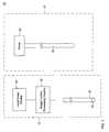
- FIG. 1illustrates an exemplary ablation lesion visualization system 10 according to an embodiment of the invention for visualizing the extent and/or depth of an ablation lesion.
- the ablation visualization system 10generally comprises an injection subsystem 45 for injecting contrast agent into the body and an imaging subsystem 15 that is responsive to the contrast agent.
- the injection subsystem 45comprises an injection catheter 55 , and an infusion pump 50 fluidly coupled to the proximal end of the catheter 55 .
- the injection catheter 55is constructed for insertion into a blood vessel (e.g., an artery) and is preferably made of a flexible material so that it can bend along the tortuous path of the blood vessel.
- the injection catheter 55comprises a catheter body 215 having a lumen 225 extending therethrough, and an opening 235 at its distal tip.
- the lumen 225fluidly couples the pump 50 (not shown in FIG. 2) to the opening 235 at the distal tip of the catheter body 215 .
- the opening 235may be located on the side of the catheter body 215 near the distal tip.
- injection catheter 55 described aboveis merely illustrative and that the invention may use any one of a number of injection catheters known in the art for injecting diagnostic and/or therapeutic agents into a blood vessel.
- injection catheters commonly used in “angiography” procedures for visualizing blood vessel structures in a fluoroscopic image with radiopaque dyecan be used.
- These injection catheterstypically have an outer diameter of 3-4 French.
- the imaging subsystem 15comprises a peripheral imaging device 20 , image control/processing circuitry 35 coupled to the imaging device 20 , and an image display 40 coupled to the image control/processing circuitry 35 .
- the imaging device 20may be constructed for insertion into the body, e.g., a catheter, to image the interior of the body. Alternatively, the imaging device 20 may be an external imaging device that images the interior of the body from a position outside the body.
- the imaging device 20comprises an imaging element 25 , e.g., a rotating ultrasound imager, a phased array ultrasound imager, or the like.
- the imaging element 25produces signals, e.g., electrical signals, representing the interior of the body and outputs these signals to the image control/processing circuitry 35 .
- the image control/processing circuitry 35processes these signals into local interior images of the body and displays the interior images on the image display 40 .
- FIG. 3illustrates an ultrasound-based local imaging subsystem 15 according to one embodiment of the invention, in which the imaging device 20 takes the form of an ultrasound imaging device 20 and the imaging element(s) 25 takes the form of one or more ultrasound transducer(s) 25 .
- the ultrasound transducer(s) 25may be rotated within the imaging device 20 by a drive shaft coupled to a drive motor (not shown) in order to obtain cross-sectional images (i.e. “slices”) of the body.
- the ultrasound transducer(s) 25may be arranged in a one-or-two dimensional phased array on the imaging device 20 for imaging a plane and/or sector of the body.
- the image control/processing circuitry 35further includes an electrical pulse generator 315 and an electrical signal receiver 320 , both of which are coupled to the ultrasound transducer(s) 25 .
- the ultrasound image control/processing circuitry 35further includes an ultrasound image processor 330 coupled to the electrical signal receiver 220 .
- the imaging device 20may be inserted into the body or placed on the skin surface of the body with the ultrasound transducer(s) 25 directed towards the interior of the body.
- the pulse generator 315transmits electrical pulses to excite the ultrasound transducer(s) 25 .
- the transducer(s) 25convert the electrical pulses into pulses of ultrasound energy, which are emitted in the body. A portion of the ultrasound energy is reflected off of the internal anatomy of the body back to the transducer(s) 25 .
- the transducer(s) 25convert the back-reflected ultrasound energy into electrical signals representing the interior of the body.
- the electrical signalsare detected by the electrical signal receiver 320 and outputted to the ultrasound image processor 330 , which processes the received electrical signals into an ultrasound image of the body using known ultrasound image processing methods.
- the electrical signal receiver 320may amplify and/or filter the electrical signals before outputting them to the ultrasound image processor 330 .
- the ultrasound image processor 330displays the ultrasound image on the image display 40 .
- a three-dimensional ultrasound imagemay be obtained from an ultrasound imaging device 20 that is only capable of imaging two-dimensional cross-sections of the body. This is done by having the ultrasound imaging device 20 sequentially image different cross-sections of the body and aggregating (i.e., piecing together) the cross-sectional images of the body to construct a 3-D image of the body.
- the ultrasound imaging device 20may image the different cross-sections of the body by mechanically moving the transducer 25 to different locations within the body and obtaining cross-sectional images at the different locations.
- FIG. 4illustrates a cross-sectional view of an embodiment of an ultrasonic imaging catheter 20 , in which the ultrasound transducer(s) 25 takes the form of a rotating ultrasound imaging transducer 25 .
- the imaging catheter 20comprises an elongated catheter body or sheath 415 having a lumen 425 extending therethrough.
- the catheter body 415is made of a flexible material so that it is able to bend along the path of a body lumen.
- the imaging device 20further includes a drive shaft 430 extending through the lumen 425 .
- the rotating ultrasound imaging transducer 25is mounted on the distal end of the drive shaft 430 .
- the catheter body 415includes a clear acoustic window (not shown) for allowing ultrasound pulses to pass through the catheter body 415 .
- the lumen 425may be filled with fluid, e.g., water, to better couple ultrasound energy from the ultrasound transducer 25 to the surrounding body.
- fluide.g., water
- An example of this type of imaging catheteris the 9-F (French) 9-MHz Intracardiac Echocardiography “ICE” catheter commercialized by Boston Scientific.
- the imaging transducer 25is mechanically rotated one revolution (360 degrees) along its axis 440 while simultaneously emitting ultrasound pulses at different angular directions in the body.
- the ultrasound image processor 330processes the electrical signals received during one revolution of the ultrasound transducer 25 to construct the cross-sectional image of the body.
- the local imaging subsystem 35may continuously update the ultrasound image to provide a real-time image of the body.
- the ultrasound transducer 25may be displaced axially within the catheter body 415 by, e.g., pulling back the drive shaft 430 .
- the ultrasound transducer 25is rotated to obtain multiple cross-sectional images (i.e., “slices”) of the body at different positions within the body.
- the ultrasound image processor 330then aggregates (i.e., pieces together) the multiple cross-sectional images to reconstruct the volume of the body using known volume reconstruction methods. Further details on this 3-D imaging technique can be found in U.S. Pat. No. 5,724,978 to Tenhoff entitled “Enhanced accuracy of three-dimensional intraluminal ultrasound (ILUS) image reconstruction,” which is fully and expressly incorporated herein by reference.
- ILUSintraluminal ultrasound
- the physicianBefore producing and visualizing an ablation lesion in the heart, the physician must first locate the source and/or pathway within a heart chamber causing arrhythmia. Typically, the physician does this by mapping the electrical activity of the heart camber using, e.g., an EP catheter equipped with mapping electrodes and location sensors, as is known in the art. The physician then examines the map of the electrical activity of the heart chamber on a display to identify and locate the source and/or pathway of the arrhythmia.
- the EP cathetermay also be equipped with pacing electrodes for inducing arrhythmia during the mapping procedure to ensure that the abnormal electrical activity associated with the arrhythmia is shown on the map of the electrical activity of the heart chamber.
- an ablation lesionis created at a targeted site where the source and/or pathway of the arrhythmia has been located.
- the ablation lesionmay be created by heating the tissue at the targeted site by applying RF energy, laser energy, and/or direct current to the tissue.
- the EP catheter used to map the electrical activity of the heartmay include one or more ablation electrodes for applying RF energy to the targeted site.
- the ablation lesionmay also be created by injecting a chemical (e.g., ethanol) and/or cryogenic fluid into the tissue at the targeted site.
- the tissue in the ablation lesionis characterized by necrosis (i.e., dead tissue).
- necrosisi.e., dead tissue
- the capillaries in the ablation lesionare closed, stopping blood flow to the tissue in the ablation lesion.
- the ablation lesionmay be a focal or a linear ablation lesion.
- a focal ablation lesionis localized around a focal point, and a linear ablation lesion extends (e.g., a few centimeters) along a line.
- a linear lesionmay be created, e.g., by dragging an ablation electrode along the heart wall, creating several closely spaced lesions and/or using a long ablation electrode.
- a supply of contrast agentis fluidly coupled to the infusion pump 50 , e.g., from a syringe containing the contrast agent.
- the contrast agentcontains echogenic particles in a solution.
- the echogenic particlesare made of a material that reflects ultrasound waves such as albumine-based compounds.
- the materialmay reflect ultrasound waves in the body by having a higher density than blood and body tissue.
- the echogenic particlesare each comparable in size to a red blood cell (a few microns) so that they can pass through the capillary structures of the body without causing blockage.
- the echogenic particlesmay take the form of microbubbles with each microbubble, preferably, having a diameter of less than 8 microns. Examples of suitable contrast agents containing echogenic microbubbles include OPTISON and ALBUMEX.
- the distal tip of the injection catheter 55is positioned in a coronary artery that feeds blood to the tissue surrounding the ablation lesion.
- the injection catheter 55may be guided in the artery using fluoroscopy, e.g., by placing a radiopaque marker on the distal tip of the catheter 55 for identifying the location of the distal tip in a fluoroscopic image.
- step 520is illustrated in FIG. 6, in which the injection catheter 55 is positioned in the left coronary artery 620 .
- a section of the left coronary artery 620is cutaway in FIG. 6 to reveal the injection catheter 55 .
- a focal ablation lesion 630(shown in dashes) is created in the interior of the left ventricle 610 wall.
- the left coronary artery 620branches off into branches that feed blood to the heart tissue 625 surrounding the ablation lesion 630 in the left ventricle 610 .
- the contrast agentis injected into the coronary artery through the opening 235 of the injection catheter 55 .
- Thisis done by having the infusion pump 50 pump the contrast agent into the catheter lumen 225 at an injection rate of, e.g., a few milligrams per minute.
- the echogenic particles of the contrast agentshown as arrows in FIG. 6
- the particlesare able to pass through the capillaries of the live tissue 625 , and therefore perfuse throughout the live heart tissue 625 .
- the echogenic particlesdo not perfuse into the dead tissue of the ablation lesion 630 because of its closed capillaries.
- an ultrasound imageis taken of the ablation lesion 630 and surrounding tissue 625 using the ultrasound imaging device 20 .
- the ultrasound imagemay be taken from inside the heart chamber, e.g., by positioning an ultrasound imaging catheter 20 within the heart chamber.
- the ultrasound imagemay also be taken from the outside the body, e.g., by directing the ultrasound transducer(s) of an external ultrasound imaging device 20 towards the heart chamber.
- the live tissue 625reflects more of the ultrasound waves emitted from the ultrasound imaging device 20 than the ablation lesion 630 .
- This contrastenables a physician to discern the ablation lesion 630 in the ultrasound image, and therefore ascertain the extent and/or depth of the ablation lesion 630 in the myocardium from the ultrasound image.
- FIG. 7An example of an ultrasound image obtained using the ablation visualization method is illustrated in FIG. 7 .
- the ultrasound imageshows a cross-section of a heart chamber containing the ablation lesion 630 .
- the ablation lesion 630appears as a dark region
- the live tissue 625 in the heart chamber wall 740 surrounding the ablation lesion 630appears as a white region due to the presence of echogenic particles in the live tissue 625 .
- the dark region of the ablation lesion 630is located within the white region of the surrounding live tissue 625 .
- the interior volume 730 of the heart chambermay appear as a dark region (shown in FIG. 7) or a bright region, depending on the amount of time lapsed since the injection of the contrast agent. The contrast agent will ultimately arrive inside the chamber, thereby brighten it up, as explained further below.
- the ablation visualization methodmay be used to provide a physician with valuable feedback on the extent and/or depth of an ablation lesion during an ablation procedure.
- the physicianmay create an ablation lesion at a targeted site, and use the ablation visualization method to measure the extent and/or depth of the ablation lesion. Based on this measurement, the physician may determine whether the ablation lesion has sufficient extent and/or depth to treat the arrhythmia or further ablation is needed.
- the physicianmay repeat ablation followed by ablation visualization a number of times until he or she determines that the ablation has reached sufficient extent and/or depth to treat the arrhythmia.
- the contrast leveldepends of the amount of echogenic particles present in the live tissue during ultrasound imaging.
- the amount of echogenic particles in the live tissueis affected by the contrast agent injection rate and the perfusion rate of the live tissue.
- the injection ratedetermines the rate at which the particles enter the capillaries of the surrounding live tissue
- the perfusion ratedetermines the rate at which the particles exits the capillaries of the surrounding live tissue to the rest of the circulatory system.
- the perfusion ratevaries from patient to patient, and depends on such factors as the health of the patient, the age of the patient, and the like.
- a physicianmay not initially know the injection rate needed to provide a sufficient amount of echogenic particles in the surrounding live tissue to obtain adequate contrast between the ablation lesion and the surrounding live tissue in the ultrasound image.
- the physicianmay begin with an initial injection rate, and increase the injection rate when there is not enough contrast for him or her to distinguish between the ablation lesion and the surrounding live tissue in the ultrasound image. The physician may continue to increase the injection rate until he or she observes adequate contrast.
- tissue ablationproduces charred tissue by causing overheating of the tissue during ablation.
- the charred tissueis typically superficial, being localized on the surface of the ablation lesion.
- Charred tissuehas a higher density than non-charred tissue due to the absence of water in the charred tissue.
- charred tissuereflects ultrasound waves, and therefore appears bright in an ultrasound image.
- the ablation visualization methodmay provide little or no contrast between the charred tissue in an ablation lesion and the surrounding live tissue.
- the charred tissue in an ablation lesionis typically localized on the surface of he ablation lesion with the underlying tissue in the ablation lesion being non-charred. In this case, a physician may still be able to ascertain the extent and/or depth of the ablation lesion in the myocardium by visualizing the underlying non-charred tissue of the ablation lesion.
- FIG. 8illustrates an embodiment, in which the ultrasound image in step 540 is taken from within the heart chamber 810 by positioning an ultrasound imaging catheter 20 within the heart chamber 810 .
- the ultrasound transducer(s) of the imaging catheter 20may take the form of a rotating transducer within the catheter body, a phased array of transducers disposed on the catheter body, or the like.
- the ultrasound imaging catheter 20may be used to generate a 3-D ultrasound image of the ablation lesion 630 .
- the ultrasound transducer 25may be pull-backed within the catheter body 415 along the length of the ablation lesion 630 .
- the ultrasound imaging catheter 20obtains multiple cross-sectional images (i.e., slices) of the ablation lesion 630 , which are aggregated (i.e., pieced together) to generate the 3-D image of the ablation lesion 630 .
- An advantage of generating a 3-D ultrasound image of the ablation lesion 630is that it visualizes the volume of the ablation lesion 630 , allowing a physician to readily quantify both the extent and depth of the ablation lesion 630 .
- An issue that arises with imaging the ablation lesion 630 from within the heart chamber 810is that the echogenic particles perfuse into the interior of the heart chamber 810 some time after the start of the contrast agent injection.
- the echogenic particles within the interior of the heart chamber 810may reflect most or all of the ultrasound energy emitted from the ultrasound imaging catheter 20 before it reaches the ablation lesion 630 .
- the ultrasound imaging catheter 20will be unable to image the ablation lesion 630 .
- the particles within the interior of the heart chamber 810will cause the interior volume 820 of the heart chamber 810 to become white, thereby “whiting-out” the ultrasound image.
- the physicianmay decrease the injection rate of the contrast agent in order to decrease the amount of particles that perfuse into the interior volume of the heart chamber 810 .
- a tradeoff of decreasing the injection rateis that the contrast between the ablation lesion 630 and the surrounding tissue in the ultrasound image will be reduced.
- the physicianmay shorten the time interval of the ultrasound imaging so that the ultrasound imaging is completed before enough echogenic particles perfuse into the interior volume of the heart chamber 810 to “whiten-out” the ultrasound image.
- the ablation catheter used in creating the ablation lesionmay be left within the heart chamber 810 during ablation visualization.
- An example of thisis illustrated in FIG. 9, in which the ablation catheter 910 is left in the heart chamber 810 as the ultrasound imaging catheter 20 images the ablation lesion 630 .
- the ablation catheter 910may be positioned away from the ablation lesion 630 during ultrasound imaging.
- Tracking systemsare commonly employed to track the position and/or orientation of catheters (e.g., ablation catheters) and/or their functional elements (e.g., ablation electrode, mapping electrodes) within a three-dimensional (3-D) coordinate system.
- These tracking systemstypically comprise location sensors (e.g., ultrasound transducers) placed on the catheter being tracked, and a reference device that establishes the 3-D coordinate system.
- location sensorse.g., ultrasound transducers
- a reference devicethat establishes the 3-D coordinate system.
- Details of an ultrasound-type tracking systemcan be found in patent application Ser. No. 09/128,304 to Willis et al. entitled “A dynamically alterable three-dimensional graphical model of a body region,” which is fully and expressly incorporated herein by reference.
- details of a magnetic-type of tracking systemcan be found in U.S. Pat. No. 5,391,199 to Ben-Haim, entitled “Apparatus and Method for Treating Cardiac Arrhythmias,” which
- the ultrasound image of the ablation lesionis registered (i.e., aligned) with the 3-D coordinate system of a tracking system.
- a cathetere.g., ablation catheter
- An ultrasound imageis then taken of both the ablation lesion and a portion of the catheter and/or its functional elements.
- the ultrasound imageis then registered with the 3-D coordinate system by correlating the position of the catheter and/or its functional elements within the ultrasound image with the position of the catheter and/or its functional elements obtained from the tracking system.
- the ultrasound image of the ablation lesionmay also be registered with the 3-D coordinate system of a tracking system by tracking the position of the ultrasound imaging device 20 within the 3-D coordinate system. This may be done, e.g., by placing location sensors on the ultrasound imaging device 20 that are compatible with the tracking system and using the tracking system to track the position of the ultrasound imaging device 20 within the 3-D coordinate system during ultrasound imaging.
- the ultrasound imagemay then be registered (i.e., aligned) within the 3-D coordinate system by correlating the position of the ultrasound imaging device 20 relative to the ultrasound image with the position of the ultrasound imaging device 20 obtained from the tracking system.
- the inventionhas been described with reference to a specific embodiment thereof. It will, however, be evident that various modifications and changes may be made thereto without departing from the broader spirit and scope of the invention.
- the inventionis not limited to visualizing ablation lesions in the heart and may be used to visualize ablation lesions in other parts of the body.
- features known to those of skill in the artcan be added to the embodiment. Other processing steps known to those of ordinary skill in the art may similarly be incorporated as desired. Additionally and obviously, features may be added or subtracted as desired. Accordingly, the invention is not to be restricted except in light of the attached claims and their equivalents.
Landscapes
- Health & Medical Sciences (AREA)
- Life Sciences & Earth Sciences (AREA)
- Engineering & Computer Science (AREA)
- Surgery (AREA)
- Public Health (AREA)
- Molecular Biology (AREA)
- Veterinary Medicine (AREA)
- Nuclear Medicine, Radiotherapy & Molecular Imaging (AREA)
- Biomedical Technology (AREA)
- Heart & Thoracic Surgery (AREA)
- Medical Informatics (AREA)
- General Health & Medical Sciences (AREA)
- Animal Behavior & Ethology (AREA)
- Biophysics (AREA)
- Pathology (AREA)
- Physics & Mathematics (AREA)
- Radiology & Medical Imaging (AREA)
- Hematology (AREA)
- Robotics (AREA)
- Ultra Sonic Daignosis Equipment (AREA)
Abstract
Description
The invention relates generally to tissue ablation and more particularly to systems and methods for visualizing ablated tissue.
In order for the heart to beat regularly and pump blood efficiently, special conductive tissues in the heart emit electrical pulses that conduct throughout the heart. As the electrical pulses conduct through the heart, they initiate contractions of the heart muscles (i.e., myocardium) causing the heart muscles to contract in an orderly sequence. Diseased heart tissue may disrupt the normal conduction of the electrical impulses and/or produce abnormal electrical activity in the heart, resulting in cardiac arrhythmia. For example, diseased heart tissue may cause electrical pulses to cycle repeatedly within a local region of the heart, inducing sustained twitching of the heart.
Cardiac arrhythmia is commonly treated using a steerable electrophysiological (“EP”) catheter that may be precisely positioned anywhere in the heart. The EP catheter is generally used during two distinct phases of treatment for the arrhythmia. In one phase of treatment, the catheter is used to map the electrical activity of the heart in order to identify and locate the source and/or pathway of the abnormal electrical activity associated with the arrhythmia. This procedure is commonly referred to as “mapping”. During the other phase of treatment, the same catheter is used to create an ablation lesion at the site where the diseased heart tissue has been located. This procedure is commonly referred to as “ablation”.
Ablation procedures using EP catheters are typically performed using radio frequency (“RF”) energy. In this regard, an EP catheter has one or more ablation electrode(s) located at its distal end. In order to create an ablation lesion at a targeted site, the EP catheter is steered within the heart to position the ablation electrode(s) at the targeted site. Typically, the ablation electrode(s) are placed in contact with the endocardium (inner heart wall) of the targeted site. The ablation electrode(s) then applies RF energy to the targeted site. The applied RF energy causes resistance heating of the tissue adjacent to the ablation electrode(s), producing an ablation lesion at the targeted site.
Successful treatment of cardiac arrhythmia requires that the ablation lesion have a sufficient extent and depth in the myocardium (heart muscle) to effectively eliminate the source and/or pathway of the abnormal electrical activity associated with the arrhythmia. Therefore, systems and methods for visualizing the extent and/or depth of ablation lesions would be highly desirable.
The present inventions are directed to a method for visualizing an ablation lesion. The inventive method comprises injecting a contrast agent into an artery that feeds blood to live tissue surrounding the ablation lesion, and imaging the ablation lesion and the surrounding live tissue with an imager that is responsive to the contrast agent. By way of non-limiting example, the ablation lesion can be located under the endocardial surface of a heart, in which case, the artery can be a coronary artery that feeds live heart tissue. The contrast agent can comprise echogenic particles, e.g., microbubbles, which are typically small enough (e.g., less than 8 microns) to pass through capillaries, so that the open capillaries in the live tissue allow the contrast agent to perfuse therein, while the closed capillaries in the nonviable tissue of the ablation lesion prevent the contrast agent from perfusing therein. In the case of a contrast agent that comprises echogenic particles, the imager can take the form of an interior or exterior ultrasound imager. It should be emphasized, however, that although the preferred embodiment describes an echogenic-based contrast agent and an ultrasound imaging as its preferred means for imaging the ablation lesion, the present invention should not be so limited, and contemplates any contrast agent that is able to distinguish between live tissue and ablated tissue and any imager that is responsive to the contrast agent. For example, optical, MRI or CT imaging technologies may be used with an appropriate type of contrast enhancing agent.
The drawings illustrate the design and utility of preferred embodiments of the present invention, in which similar elements are referred to by common reference numerals. In order to better appreciate how the above-recited and other advantages and objects of the present inventions are obtained, a more particular description of the present inventions briefly described above will be rendered by reference to specific embodiments thereof, which are illustrated in the accompanying drawings. Understanding that these drawings depict only typical embodiments of the invention and are not therefore to be considered limiting of its scope, the invention will be described and explained with additional specificity and detail through the use of the accompanying drawings in which:
FIG. 1 illustrates the components of an ablation imaging system according to an embodiment of the invention;
FIG. 2 illustrates a cross-sectional view of the distal end of an injection catheter used by the ablation lesion imaging system of FIG. 1;
FIG. 3 illustrates an ultrasound imaging subsystem used by the ablation lesion imaging system of FIG. 1;
FIG. 4 illustrates a cross-sectional view of an ultrasound imaging catheter used in the ultrasound imaging subsystem of FIG. 3;
FIG. 5 is a flowchart illustrating an ablation lesion visualization method that may be performed by the ablation imaging system of FIG. 1;
FIG. 6 illustrates the placement of an injection catheter in a patient's coronary artery in accordance with a step of the method of FIG. 5;
FIG. 7 illustrates an example of an ultrasound image of an ablation lesion obtained from the ablation lesion visualization method of FIG. 5;
FIG. 8 illustrates the placement of an ultrasound imaging catheter within a patient's heart chamber in accordance with an imaging step of the method of FIG. 5; and
FIG. 9 illustrates the placement of an ultrasound imaging catheter and an ablation catheter within a patient's heart chamber in accordance with an imaging step of the method of FIG.5.
FIG. 1 illustrates an exemplary ablationlesion visualization system 10 according to an embodiment of the invention for visualizing the extent and/or depth of an ablation lesion. Theablation visualization system 10 generally comprises aninjection subsystem 45 for injecting contrast agent into the body and animaging subsystem 15 that is responsive to the contrast agent.
Theinjection subsystem 45 comprises aninjection catheter 55, and aninfusion pump 50 fluidly coupled to the proximal end of thecatheter 55. Theinjection catheter 55 is constructed for insertion into a blood vessel (e.g., an artery) and is preferably made of a flexible material so that it can bend along the tortuous path of the blood vessel. Referring to FIG. 2, theinjection catheter 55 comprises acatheter body 215 having alumen 225 extending therethrough, and anopening 235 at its distal tip. Thelumen 225 fluidly couples the pump50 (not shown in FIG. 2) to theopening 235 at the distal tip of thecatheter body 215. Alternatively, the opening235 may be located on the side of thecatheter body 215 near the distal tip.
It is to be understood that theinjection catheter 55 described above is merely illustrative and that the invention may use any one of a number of injection catheters known in the art for injecting diagnostic and/or therapeutic agents into a blood vessel. For example, injection catheters commonly used in “angiography” procedures for visualizing blood vessel structures in a fluoroscopic image with radiopaque dye can be used. These injection catheters typically have an outer diameter of 3-4 French.
Referring back to FIG. 1, theimaging subsystem 15 comprises aperipheral imaging device 20, image control/processing circuitry 35 coupled to theimaging device 20, and animage display 40 coupled to the image control/processing circuitry 35. Theimaging device 20 may be constructed for insertion into the body, e.g., a catheter, to image the interior of the body. Alternatively, theimaging device 20 may be an external imaging device that images the interior of the body from a position outside the body. Theimaging device 20 comprises animaging element 25, e.g., a rotating ultrasound imager, a phased array ultrasound imager, or the like. Theimaging element 25 produces signals, e.g., electrical signals, representing the interior of the body and outputs these signals to the image control/processing circuitry 35. The image control/processing circuitry 35 processes these signals into local interior images of the body and displays the interior images on theimage display 40.
FIG. 3 illustrates an ultrasound-basedlocal imaging subsystem 15 according to one embodiment of the invention, in which theimaging device 20 takes the form of anultrasound imaging device 20 and the imaging element(s)25 takes the form of one or more ultrasound transducer(s)25. The ultrasound transducer(s)25 may be rotated within theimaging device 20 by a drive shaft coupled to a drive motor (not shown) in order to obtain cross-sectional images (i.e. “slices”) of the body. Alternatively, the ultrasound transducer(s)25 may be arranged in a one-or-two dimensional phased array on theimaging device 20 for imaging a plane and/or sector of the body. The image control/processing circuitry 35 further includes anelectrical pulse generator 315 and anelectrical signal receiver 320, both of which are coupled to the ultrasound transducer(s)25. The ultrasound image control/processing circuitry 35 further includes an ultrasound image processor330 coupled to the electrical signal receiver220.
To obtain an ultrasound image of the interior of the body, theimaging device 20 may be inserted into the body or placed on the skin surface of the body with the ultrasound transducer(s)25 directed towards the interior of the body. Thepulse generator 315 transmits electrical pulses to excite the ultrasound transducer(s)25. The transducer(s)25 convert the electrical pulses into pulses of ultrasound energy, which are emitted in the body. A portion of the ultrasound energy is reflected off of the internal anatomy of the body back to the transducer(s)25. The transducer(s)25 convert the back-reflected ultrasound energy into electrical signals representing the interior of the body. The electrical signals are detected by theelectrical signal receiver 320 and outputted to the ultrasound image processor330, which processes the received electrical signals into an ultrasound image of the body using known ultrasound image processing methods. Theelectrical signal receiver 320 may amplify and/or filter the electrical signals before outputting them to the ultrasound image processor330. The ultrasound image processor330 displays the ultrasound image on theimage display 40.
A three-dimensional ultrasound image may be obtained from anultrasound imaging device 20 that is only capable of imaging two-dimensional cross-sections of the body. This is done by having theultrasound imaging device 20 sequentially image different cross-sections of the body and aggregating (i.e., piecing together) the cross-sectional images of the body to construct a 3-D image of the body. Theultrasound imaging device 20 may image the different cross-sections of the body by mechanically moving thetransducer 25 to different locations within the body and obtaining cross-sectional images at the different locations.
FIG. 4 illustrates a cross-sectional view of an embodiment of anultrasonic imaging catheter 20, in which the ultrasound transducer(s)25 takes the form of a rotatingultrasound imaging transducer 25. Theimaging catheter 20 comprises an elongated catheter body orsheath 415 having alumen 425 extending therethrough. Thecatheter body 415 is made of a flexible material so that it is able to bend along the path of a body lumen. Theimaging device 20 further includes adrive shaft 430 extending through thelumen 425. The rotatingultrasound imaging transducer 25 is mounted on the distal end of thedrive shaft 430. Thecatheter body 415 includes a clear acoustic window (not shown) for allowing ultrasound pulses to pass through thecatheter body 415. Thelumen 425 may be filled with fluid, e.g., water, to better couple ultrasound energy from theultrasound transducer 25 to the surrounding body. An example of this type of imaging catheter is the 9-F (French) 9-MHz Intracardiac Echocardiography “ICE” catheter commercialized by Boston Scientific.
To obtain an interior cross-sectional image of the body, theimaging transducer 25 is mechanically rotated one revolution (360 degrees) along itsaxis 440 while simultaneously emitting ultrasound pulses at different angular directions in the body. The ultrasound image processor330 processes the electrical signals received during one revolution of theultrasound transducer 25 to construct the cross-sectional image of the body. Thelocal imaging subsystem 35 may continuously update the ultrasound image to provide a real-time image of the body.
To obtain a three-dimensional image of a body volume, theultrasound transducer 25 may be displaced axially within thecatheter body 415 by, e.g., pulling back thedrive shaft 430. As thetransducer 25 is displaced axially, theultrasound transducer 25 is rotated to obtain multiple cross-sectional images (i.e., “slices”) of the body at different positions within the body. The ultrasound image processor330 then aggregates (i.e., pieces together) the multiple cross-sectional images to reconstruct the volume of the body using known volume reconstruction methods. Further details on this 3-D imaging technique can be found in U.S. Pat. No. 5,724,978 to Tenhoff entitled “Enhanced accuracy of three-dimensional intraluminal ultrasound (ILUS) image reconstruction,” which is fully and expressly incorporated herein by reference.
Before producing and visualizing an ablation lesion in the heart, the physician must first locate the source and/or pathway within a heart chamber causing arrhythmia. Typically, the physician does this by mapping the electrical activity of the heart camber using, e.g., an EP catheter equipped with mapping electrodes and location sensors, as is known in the art. The physician then examines the map of the electrical activity of the heart chamber on a display to identify and locate the source and/or pathway of the arrhythmia. The EP catheter may also be equipped with pacing electrodes for inducing arrhythmia during the mapping procedure to ensure that the abnormal electrical activity associated with the arrhythmia is shown on the map of the electrical activity of the heart chamber.
During the ablation procedure, an ablation lesion is created at a targeted site where the source and/or pathway of the arrhythmia has been located. The ablation lesion may be created by heating the tissue at the targeted site by applying RF energy, laser energy, and/or direct current to the tissue. For example, the EP catheter used to map the electrical activity of the heart may include one or more ablation electrodes for applying RF energy to the targeted site. The ablation lesion may also be created by injecting a chemical (e.g., ethanol) and/or cryogenic fluid into the tissue at the targeted site.
The tissue in the ablation lesion is characterized by necrosis (i.e., dead tissue). In addition, the capillaries in the ablation lesion are closed, stopping blood flow to the tissue in the ablation lesion. The ablation lesion may be a focal or a linear ablation lesion. A focal ablation lesion is localized around a focal point, and a linear ablation lesion extends (e.g., a few centimeters) along a line. A linear lesion may be created, e.g., by dragging an ablation electrode along the heart wall, creating several closely spaced lesions and/or using a long ablation electrode.
A method for visualizing the ablation lesion according to an embodiment of the invention will now be described with reference to FIG.5.
Instep 510, a supply of contrast agent is fluidly coupled to theinfusion pump 50, e.g., from a syringe containing the contrast agent. In one embodiment of the invention, the contrast agent contains echogenic particles in a solution. Preferably, the echogenic particles are made of a material that reflects ultrasound waves such as albumine-based compounds. For example, the material may reflect ultrasound waves in the body by having a higher density than blood and body tissue. The echogenic particles are each comparable in size to a red blood cell (a few microns) so that they can pass through the capillary structures of the body without causing blockage. The echogenic particles may take the form of microbubbles with each microbubble, preferably, having a diameter of less than 8 microns. Examples of suitable contrast agents containing echogenic microbubbles include OPTISON and ALBUMEX.
Instep 520, the distal tip of theinjection catheter 55 is positioned in a coronary artery that feeds blood to the tissue surrounding the ablation lesion. Theinjection catheter 55 may be guided in the artery using fluoroscopy, e.g., by placing a radiopaque marker on the distal tip of thecatheter 55 for identifying the location of the distal tip in a fluoroscopic image.
An example ofstep 520 is illustrated in FIG. 6, in which theinjection catheter 55 is positioned in the leftcoronary artery 620. A section of the leftcoronary artery 620 is cutaway in FIG. 6 to reveal theinjection catheter 55. In this illustrative example, a focal ablation lesion630 (shown in dashes) is created in the interior of theleft ventricle 610 wall. The leftcoronary artery 620 branches off into branches that feed blood to theheart tissue 625 surrounding theablation lesion 630 in theleft ventricle 610.
Referring back to FIG. 5, instep 530, the contrast agent is injected into the coronary artery through theopening 235 of theinjection catheter 55. This is done by having theinfusion pump 50 pump the contrast agent into thecatheter lumen 225 at an injection rate of, e.g., a few milligrams per minute. From the coronary artery, the echogenic particles of the contrast agent (shown as arrows in FIG. 6) perfuse into thelive tissue 625 surrounding the ablation lesion. Because of their small size, the particles are able to pass through the capillaries of thelive tissue 625, and therefore perfuse throughout thelive heart tissue 625. The echogenic particles, however, do not perfuse into the dead tissue of theablation lesion 630 because of its closed capillaries.
Instep 540, during or after contrast agent injection, an ultrasound image is taken of theablation lesion 630 and surroundingtissue 625 using theultrasound imaging device 20. The ultrasound image may be taken from inside the heart chamber, e.g., by positioning anultrasound imaging catheter 20 within the heart chamber. The ultrasound image may also be taken from the outside the body, e.g., by directing the ultrasound transducer(s) of an externalultrasound imaging device 20 towards the heart chamber.
Because of the perfusion of the echogenic particles into thelive tissue 625 surrounding theablation lesion 620, thelive tissue 625 reflects more of the ultrasound waves emitted from theultrasound imaging device 20 than theablation lesion 630. This causes the surroundinglive tissue 625 to appear brighter in the ultrasound image than theablation lesion 630, thereby providing contrast between theablation lesion 630 and the surroundinglive tissue 625 in the ultrasound image. This contrast enables a physician to discern theablation lesion 630 in the ultrasound image, and therefore ascertain the extent and/or depth of theablation lesion 630 in the myocardium from the ultrasound image.
An example of an ultrasound image obtained using the ablation visualization method is illustrated in FIG.7. The ultrasound image shows a cross-section of a heart chamber containing theablation lesion 630. In the ultrasound image, theablation lesion 630 appears as a dark region, while thelive tissue 625 in theheart chamber wall 740 surrounding theablation lesion 630 appears as a white region due to the presence of echogenic particles in thelive tissue 625. The dark region of theablation lesion 630 is located within the white region of the surroundinglive tissue 625. The interior volume730 of the heart chamber may appear as a dark region (shown in FIG. 7) or a bright region, depending on the amount of time lapsed since the injection of the contrast agent. The contrast agent will ultimately arrive inside the chamber, thereby brighten it up, as explained further below.
The ablation visualization method may be used to provide a physician with valuable feedback on the extent and/or depth of an ablation lesion during an ablation procedure. For example, the physician may create an ablation lesion at a targeted site, and use the ablation visualization method to measure the extent and/or depth of the ablation lesion. Based on this measurement, the physician may determine whether the ablation lesion has sufficient extent and/or depth to treat the arrhythmia or further ablation is needed. The physician may repeat ablation followed by ablation visualization a number of times until he or she determines that the ablation has reached sufficient extent and/or depth to treat the arrhythmia.
Visualization of the ablation lesion requires that the contrast between the ablation lesion and surrounding live tissue in the ultrasound image be high enough to distinguish between the ablation lesion and the surrounding live tissue. The contrast level depends of the amount of echogenic particles present in the live tissue during ultrasound imaging. The amount of echogenic particles in the live tissue is affected by the contrast agent injection rate and the perfusion rate of the live tissue. The injection rate determines the rate at which the particles enter the capillaries of the surrounding live tissue, while the perfusion rate determines the rate at which the particles exits the capillaries of the surrounding live tissue to the rest of the circulatory system. The perfusion rate varies from patient to patient, and depends on such factors as the health of the patient, the age of the patient, and the like. As a result, a physician may not initially know the injection rate needed to provide a sufficient amount of echogenic particles in the surrounding live tissue to obtain adequate contrast between the ablation lesion and the surrounding live tissue in the ultrasound image. In this case, the physician may begin with an initial injection rate, and increase the injection rate when there is not enough contrast for him or her to distinguish between the ablation lesion and the surrounding live tissue in the ultrasound image. The physician may continue to increase the injection rate until he or she observes adequate contrast.
In some cases, tissue ablation produces charred tissue by causing overheating of the tissue during ablation. In RF ablation, for example, the charred tissue is typically superficial, being localized on the surface of the ablation lesion. Charred tissue has a higher density than non-charred tissue due to the absence of water in the charred tissue. As a result, charred tissue reflects ultrasound waves, and therefore appears bright in an ultrasound image. Because charred tissue appears bright in an ultrasound image, the ablation visualization method may provide little or no contrast between the charred tissue in an ablation lesion and the surrounding live tissue. Fortunately, the charred tissue in an ablation lesion is typically localized on the surface of he ablation lesion with the underlying tissue in the ablation lesion being non-charred. In this case, a physician may still be able to ascertain the extent and/or depth of the ablation lesion in the myocardium by visualizing the underlying non-charred tissue of the ablation lesion.
FIG. 8 illustrates an embodiment, in which the ultrasound image instep 540 is taken from within theheart chamber 810 by positioning anultrasound imaging catheter 20 within theheart chamber 810. The ultrasound transducer(s) of theimaging catheter 20 may take the form of a rotating transducer within the catheter body, a phased array of transducers disposed on the catheter body, or the like. Theultrasound imaging catheter 20 may be used to generate a 3-D ultrasound image of theablation lesion 630. For example, using theultrasound imaging catheter 20 of FIG. 4, theultrasound transducer 25 may be pull-backed within thecatheter body 415 along the length of theablation lesion 630. As thetransducer 25 is pulled-back, theultrasound imaging catheter 20 obtains multiple cross-sectional images (i.e., slices) of theablation lesion 630, which are aggregated (i.e., pieced together) to generate the 3-D image of theablation lesion 630. An advantage of generating a 3-D ultrasound image of theablation lesion 630 is that it visualizes the volume of theablation lesion 630, allowing a physician to readily quantify both the extent and depth of theablation lesion 630.
An issue that arises with imaging theablation lesion 630 from within theheart chamber 810 is that the echogenic particles perfuse into the interior of theheart chamber 810 some time after the start of the contrast agent injection. When this occurs, the echogenic particles within the interior of theheart chamber 810 may reflect most or all of the ultrasound energy emitted from theultrasound imaging catheter 20 before it reaches theablation lesion 630. As a result, theultrasound imaging catheter 20 will be unable to image theablation lesion 630. In addition, the particles within the interior of theheart chamber 810 will cause theinterior volume 820 of theheart chamber 810 to become white, thereby “whiting-out” the ultrasound image. When this occurs, the physician may decrease the injection rate of the contrast agent in order to decrease the amount of particles that perfuse into the interior volume of theheart chamber 810. A tradeoff of decreasing the injection rate, however, is that the contrast between theablation lesion 630 and the surrounding tissue in the ultrasound image will be reduced. Alternatively or in addition, the physician may shorten the time interval of the ultrasound imaging so that the ultrasound imaging is completed before enough echogenic particles perfuse into the interior volume of theheart chamber 810 to “whiten-out” the ultrasound image.
The ablation catheter used in creating the ablation lesion may be left within theheart chamber 810 during ablation visualization. An example of this is illustrated in FIG. 9, in which theablation catheter 910 is left in theheart chamber 810 as theultrasound imaging catheter 20 images theablation lesion 630. To prevent theablation catheter 910 from obstructing the ultrasound image of theablation lesion 630, theablation catheter 910 may be positioned away from theablation lesion 630 during ultrasound imaging. An advantage of leaving theablation catheter 910 within theheart chamber 910 is that it makes it easier for a physician to perform further ablation, when necessary, after ablation visualization.
Tracking systems are commonly employed to track the position and/or orientation of catheters (e.g., ablation catheters) and/or their functional elements (e.g., ablation electrode, mapping electrodes) within a three-dimensional (3-D) coordinate system. These tracking systems typically comprise location sensors (e.g., ultrasound transducers) placed on the catheter being tracked, and a reference device that establishes the 3-D coordinate system. Details of an ultrasound-type tracking system can be found in patent application Ser. No. 09/128,304 to Willis et al. entitled “A dynamically alterable three-dimensional graphical model of a body region,” which is fully and expressly incorporated herein by reference. Also, details of a magnetic-type of tracking system can be found in U.S. Pat. No. 5,391,199 to Ben-Haim, entitled “Apparatus and Method for Treating Cardiac Arrhythmias,” which is fully and expressly incorporated herein by reference.
In one embodiment of the invention, the ultrasound image of the ablation lesion is registered (i.e., aligned) with the 3-D coordinate system of a tracking system. To do this, a catheter (e.g., ablation catheter) whose position is tracked by the tracking system is left within the heart chamber. An ultrasound image is then taken of both the ablation lesion and a portion of the catheter and/or its functional elements. The ultrasound image is then registered with the 3-D coordinate system by correlating the position of the catheter and/or its functional elements within the ultrasound image with the position of the catheter and/or its functional elements obtained from the tracking system.
The ultrasound image of the ablation lesion may also be registered with the 3-D coordinate system of a tracking system by tracking the position of theultrasound imaging device 20 within the 3-D coordinate system. This may be done, e.g., by placing location sensors on theultrasound imaging device 20 that are compatible with the tracking system and using the tracking system to track the position of theultrasound imaging device 20 within the 3-D coordinate system during ultrasound imaging. The ultrasound image may then be registered (i.e., aligned) within the 3-D coordinate system by correlating the position of theultrasound imaging device 20 relative to the ultrasound image with the position of theultrasound imaging device 20 obtained from the tracking system.
In the foregoing specification, the invention has been described with reference to a specific embodiment thereof. It will, however, be evident that various modifications and changes may be made thereto without departing from the broader spirit and scope of the invention. For example, the invention is not limited to visualizing ablation lesions in the heart and may be used to visualize ablation lesions in other parts of the body. As another example, features known to those of skill in the art can be added to the embodiment. Other processing steps known to those of ordinary skill in the art may similarly be incorporated as desired. Additionally and obviously, features may be added or subtracted as desired. Accordingly, the invention is not to be restricted except in light of the attached claims and their equivalents.
Claims (16)
1. A method for visualizing an ablation lesion, comprising:
injecting a contrast agent into an artery that feeds blood to live tissue surrounding the ablation lesion;
positioning an imager responsive to the contrast agent within a space adjacent the live tissue;
imaging the ablation lesion and the surrounding live tissue with the imager; and
minimizing the perfusion rate of the contrast agent from live tissue into the space to prevent interference of the imaging.
2. The method ofclaim 1 , wherein the ablation lesion is located in the heart and the space is a heart chamber.
3. The method ofclaim 1 , wherein the step of injecting the contrast agent into the artery comprises:
positioning an injection catheter in the artery; and
injecting the contrast agent into the artery through the injection catheter.
4. The method ofclaim 1 , wherein the imaging step comprises:
imaging multiple cross sections of the ablation lesion and the surrounding tissue; and
aggregating the multiple cross-sectional images to generate a three-dimensional image of the ablation lesion and the surrounding tissue.
5. The method ofclaim 1 , further comprising:
registering the image of the ablation lesion and the surrounding tissue with a three-dimensional coordinate system.
6. The method ofclaim 1 , further comprising:
increasing the injection rate of the contrast agent in the injection step when the image of the ablation lesion and the surrounding tissue lacks sufficient contrast to distinguish between the ablation lesion and the surrounding tissue in the image.
7. The method ofclaim 1 , further comprising:
decreasing the injection rate of the contrast agent in the injection step when perfusion of the contrast agent into the space interferes with the imaging.
8. A method for visualizing an ablation lesion, comprising:
injecting a contrast agent into an artery that feeds blood to live tissue surrounding the ablation lesion, wherein the contrast agent comprises echogenic particles;
positioning an ultrasound imager responsive to the contrast agent within a space adjacent the live tissue;
imaging the ablation lesion and the surrounding live tissue with an ultrasound imager; and
minimizing the perfusion rate of the contrast agent from the live tissue into the space to prevent whiting out of the imaging.
9. The method ofclaim 8 , wherein the echogenic particles are microbubbles.
10. The method ofclaim 9 , wherein each microbubble has a diameter of less than 8 microns.
11. The method ofclaim 8 , wherein the ablation lesion is located in the heart and the space is a heart chamber.
12. The method ofclaim 8 , wherein the imaging step comprises:
imaging multiple cross sections of the ablation lesion and the surrounding tissue; and
aggregating the multiple cross-sectional images to generate a three-dimensional image of the ablation lesion and the surrounding tissue.
13. The method ofclaim 12 , wherein the step of imaging the multiple cross section comprises:
pulling back a ultrasound transducer within the ultrasound imager.
14. The method ofclaim 8 , further comprising:
registering the image of the ablation lesion and the surrounding tissue with a three-dimensional coordinate system.
15. The method of claim further comprising:
increasing the injection rate of the contrast agent in the injection step when the image of the ablation lesion and the surrounding tissue lacks sufficient contrast to distinguish between the ablation lesion and the surrounding tissue in the image.
16. The method ofclaim 8 , further comprising:
decreasing the injection rate of the contrast agent in the injection step when perfusion of the contrast agent into the space whites out the imaging.
Priority Applications (1)
| Application Number | Priority Date | Filing Date | Title |
|---|---|---|---|
| US10/139,994US6746401B2 (en) | 2002-05-06 | 2002-05-06 | Tissue ablation visualization |
Applications Claiming Priority (1)
| Application Number | Priority Date | Filing Date | Title |
|---|---|---|---|
| US10/139,994US6746401B2 (en) | 2002-05-06 | 2002-05-06 | Tissue ablation visualization |
Publications (2)
| Publication Number | Publication Date |
|---|---|
| US20030208123A1 US20030208123A1 (en) | 2003-11-06 |
| US6746401B2true US6746401B2 (en) | 2004-06-08 |
Family
ID=29269631
Family Applications (1)
| Application Number | Title | Priority Date | Filing Date |
|---|---|---|---|
| US10/139,994Expired - LifetimeUS6746401B2 (en) | 2002-05-06 | 2002-05-06 | Tissue ablation visualization |
Country Status (1)
| Country | Link |
|---|---|
| US (1) | US6746401B2 (en) |
Cited By (146)
| Publication number | Priority date | Publication date | Assignee | Title |
|---|---|---|---|---|
| US20040023717A1 (en)* | 2002-07-30 | 2004-02-05 | Jumpei Tsuda | Program, recording medium, game character rendering method, and game apparatus |
| US20060100514A1 (en)* | 2002-07-08 | 2006-05-11 | Prorhythm, Inc. | Cardiac ablation using microbubbles |
| US20060285104A1 (en)* | 2005-06-15 | 2006-12-21 | Meagan Walsh | Molecular imager |
| WO2006135536A3 (en)* | 2005-06-09 | 2007-02-22 | Univ Miami | Papillary muscle attachement for left ventricular reduction |
| US20070129633A1 (en)* | 2005-11-23 | 2007-06-07 | Warren Lee | Ablation array having independently activated ablation elements |
| US20070129630A1 (en)* | 2005-12-07 | 2007-06-07 | Shimko Daniel A | Imaging method, device and system |
| US20080061523A1 (en)* | 2006-09-11 | 2008-03-13 | Ed Holand | Removable wheel system for footlockers |
| US20080228079A1 (en)* | 2007-03-16 | 2008-09-18 | Donaldson Brenda L | Clinical utilization of contrast agents to define specific areas within the myocardial wall to provide guidance and localization for ablation, cyroablation, or other techniques in patients with post myocardial infarction |
| US20080287777A1 (en)* | 2007-05-16 | 2008-11-20 | General Electric Company | System and method to register a tracking system with an intracardiac echocardiography (ice) imaging system |
| US20090082619A1 (en)* | 2005-06-09 | 2009-03-26 | De Marchena Eduardo | Method of treating cardiomyopathy |
| US7662177B2 (en) | 2006-04-12 | 2010-02-16 | Bacoustics, Llc | Apparatus and methods for pain relief using ultrasound waves in combination with cryogenic energy |
| US20120278711A1 (en)* | 2003-09-16 | 2012-11-01 | Labtest International, Inc. D/B/A Intertek Consumer Goods North America | Haptic response system and method of use |
| US8880185B2 (en) | 2010-06-11 | 2014-11-04 | Boston Scientific Scimed, Inc. | Renal denervation and stimulation employing wireless vascular energy transfer arrangement |
| US8939970B2 (en) | 2004-09-10 | 2015-01-27 | Vessix Vascular, Inc. | Tuned RF energy and electrical tissue characterization for selective treatment of target tissues |
| US8951251B2 (en) | 2011-11-08 | 2015-02-10 | Boston Scientific Scimed, Inc. | Ostial renal nerve ablation |
| US8974451B2 (en) | 2010-10-25 | 2015-03-10 | Boston Scientific Scimed, Inc. | Renal nerve ablation using conductive fluid jet and RF energy |
| US9023034B2 (en) | 2010-11-22 | 2015-05-05 | Boston Scientific Scimed, Inc. | Renal ablation electrode with force-activatable conduction apparatus |
| US9028485B2 (en) | 2010-11-15 | 2015-05-12 | Boston Scientific Scimed, Inc. | Self-expanding cooling electrode for renal nerve ablation |
| US9028472B2 (en) | 2011-12-23 | 2015-05-12 | Vessix Vascular, Inc. | Methods and apparatuses for remodeling tissue of or adjacent to a body passage |
| US9050106B2 (en) | 2011-12-29 | 2015-06-09 | Boston Scientific Scimed, Inc. | Off-wall electrode device and methods for nerve modulation |
| US9060761B2 (en) | 2010-11-18 | 2015-06-23 | Boston Scientific Scime, Inc. | Catheter-focused magnetic field induced renal nerve ablation |
| US9078749B2 (en) | 2007-09-13 | 2015-07-14 | Georg Lutter | Truncated cone heart valve stent |
| US9079000B2 (en) | 2011-10-18 | 2015-07-14 | Boston Scientific Scimed, Inc. | Integrated crossing balloon catheter |
| US9084609B2 (en) | 2010-07-30 | 2015-07-21 | Boston Scientific Scime, Inc. | Spiral balloon catheter for renal nerve ablation |
| US9089350B2 (en) | 2010-11-16 | 2015-07-28 | Boston Scientific Scimed, Inc. | Renal denervation catheter with RF electrode and integral contrast dye injection arrangement |
| US9119600B2 (en) | 2011-11-15 | 2015-09-01 | Boston Scientific Scimed, Inc. | Device and methods for renal nerve modulation monitoring |
| US9119632B2 (en) | 2011-11-21 | 2015-09-01 | Boston Scientific Scimed, Inc. | Deflectable renal nerve ablation catheter |
| US9125667B2 (en) | 2004-09-10 | 2015-09-08 | Vessix Vascular, Inc. | System for inducing desirable temperature effects on body tissue |
| US9125666B2 (en) | 2003-09-12 | 2015-09-08 | Vessix Vascular, Inc. | Selectable eccentric remodeling and/or ablation of atherosclerotic material |
| US9155589B2 (en) | 2010-07-30 | 2015-10-13 | Boston Scientific Scimed, Inc. | Sequential activation RF electrode set for renal nerve ablation |
| US9162046B2 (en) | 2011-10-18 | 2015-10-20 | Boston Scientific Scimed, Inc. | Deflectable medical devices |
| US9173696B2 (en) | 2012-09-17 | 2015-11-03 | Boston Scientific Scimed, Inc. | Self-positioning electrode system and method for renal nerve modulation |
| US9186209B2 (en) | 2011-07-22 | 2015-11-17 | Boston Scientific Scimed, Inc. | Nerve modulation system having helical guide |
| US9186210B2 (en) | 2011-10-10 | 2015-11-17 | Boston Scientific Scimed, Inc. | Medical devices including ablation electrodes |
| US9192790B2 (en) | 2010-04-14 | 2015-11-24 | Boston Scientific Scimed, Inc. | Focused ultrasonic renal denervation |
| US9192435B2 (en) | 2010-11-22 | 2015-11-24 | Boston Scientific Scimed, Inc. | Renal denervation catheter with cooled RF electrode |
| US9220558B2 (en) | 2010-10-27 | 2015-12-29 | Boston Scientific Scimed, Inc. | RF renal denervation catheter with multiple independent electrodes |
| US9220561B2 (en) | 2011-01-19 | 2015-12-29 | Boston Scientific Scimed, Inc. | Guide-compatible large-electrode catheter for renal nerve ablation with reduced arterial injury |
| US9265969B2 (en) | 2011-12-21 | 2016-02-23 | Cardiac Pacemakers, Inc. | Methods for modulating cell function |
| US9277955B2 (en) | 2010-04-09 | 2016-03-08 | Vessix Vascular, Inc. | Power generating and control apparatus for the treatment of tissue |
| US9297845B2 (en) | 2013-03-15 | 2016-03-29 | Boston Scientific Scimed, Inc. | Medical devices and methods for treatment of hypertension that utilize impedance compensation |
| US9326751B2 (en) | 2010-11-17 | 2016-05-03 | Boston Scientific Scimed, Inc. | Catheter guidance of external energy for renal denervation |
| US9327100B2 (en) | 2008-11-14 | 2016-05-03 | Vessix Vascular, Inc. | Selective drug delivery in a lumen |
| US9358365B2 (en) | 2010-07-30 | 2016-06-07 | Boston Scientific Scimed, Inc. | Precision electrode movement control for renal nerve ablation |
| US9364284B2 (en) | 2011-10-12 | 2016-06-14 | Boston Scientific Scimed, Inc. | Method of making an off-wall spacer cage |
| US9408661B2 (en) | 2010-07-30 | 2016-08-09 | Patrick A. Haverkost | RF electrodes on multiple flexible wires for renal nerve ablation |
| US9420955B2 (en) | 2011-10-11 | 2016-08-23 | Boston Scientific Scimed, Inc. | Intravascular temperature monitoring system and method |
| US9433760B2 (en) | 2011-12-28 | 2016-09-06 | Boston Scientific Scimed, Inc. | Device and methods for nerve modulation using a novel ablation catheter with polymeric ablative elements |
| US9463062B2 (en) | 2010-07-30 | 2016-10-11 | Boston Scientific Scimed, Inc. | Cooled conductive balloon RF catheter for renal nerve ablation |
| US9480559B2 (en) | 2011-08-11 | 2016-11-01 | Tendyne Holdings, Inc. | Prosthetic valves and related inventions |
| US9486306B2 (en) | 2013-04-02 | 2016-11-08 | Tendyne Holdings, Inc. | Inflatable annular sealing device for prosthetic mitral valve |
| US9486270B2 (en) | 2002-04-08 | 2016-11-08 | Medtronic Ardian Luxembourg S.A.R.L. | Methods and apparatus for bilateral renal neuromodulation |
| US9486355B2 (en) | 2005-05-03 | 2016-11-08 | Vessix Vascular, Inc. | Selective accumulation of energy with or without knowledge of tissue topography |
| US9510905B2 (en) | 2014-11-19 | 2016-12-06 | Advanced Cardiac Therapeutics, Inc. | Systems and methods for high-resolution mapping of tissue |
| US9517103B2 (en) | 2014-11-19 | 2016-12-13 | Advanced Cardiac Therapeutics, Inc. | Medical instruments with multiple temperature sensors |
| US9526611B2 (en) | 2013-10-29 | 2016-12-27 | Tendyne Holdings, Inc. | Apparatus and methods for delivery of transcatheter prosthetic valves |
| US9532725B2 (en) | 2014-03-07 | 2017-01-03 | Boston Scientific Scimed Inc. | Medical devices for mapping cardiac tissue |
| US9579030B2 (en) | 2011-07-20 | 2017-02-28 | Boston Scientific Scimed, Inc. | Percutaneous devices and methods to visualize, target and ablate nerves |
| US9597181B2 (en) | 2013-06-25 | 2017-03-21 | Tendyne Holdings, Inc. | Thrombus management and structural compliance features for prosthetic heart valves |
| US9610159B2 (en) | 2013-05-30 | 2017-04-04 | Tendyne Holdings, Inc. | Structural members for prosthetic mitral valves |
| US9636164B2 (en) | 2015-03-25 | 2017-05-02 | Advanced Cardiac Therapeutics, Inc. | Contact sensing systems and methods |
| US9649156B2 (en) | 2010-12-15 | 2017-05-16 | Boston Scientific Scimed, Inc. | Bipolar off-wall electrode device for renal nerve ablation |
| US9668811B2 (en) | 2010-11-16 | 2017-06-06 | Boston Scientific Scimed, Inc. | Minimally invasive access for renal nerve ablation |
| US9675454B2 (en) | 2012-07-30 | 2017-06-13 | Tendyne Holdings, Inc. | Delivery systems and methods for transcatheter prosthetic valves |
| US9687166B2 (en) | 2013-10-14 | 2017-06-27 | Boston Scientific Scimed, Inc. | High resolution cardiac mapping electrode array catheter |
| US9687167B2 (en) | 2014-03-11 | 2017-06-27 | Boston Scientific Scimed, Inc. | Medical devices for mapping cardiac tissue |
| US9693821B2 (en) | 2013-03-11 | 2017-07-04 | Boston Scientific Scimed, Inc. | Medical devices for modulating nerves |
| US9707036B2 (en) | 2013-06-25 | 2017-07-18 | Boston Scientific Scimed, Inc. | Devices and methods for nerve modulation using localized indifferent electrodes |
| US9713730B2 (en) | 2004-09-10 | 2017-07-25 | Boston Scientific Scimed, Inc. | Apparatus and method for treatment of in-stent restenosis |
| US9730600B2 (en) | 2013-10-31 | 2017-08-15 | Boston Scientific Scimed, Inc. | Medical device for high resolution mapping using localized matching |
| US9770606B2 (en) | 2013-10-15 | 2017-09-26 | Boston Scientific Scimed, Inc. | Ultrasound ablation catheter with cooling infusion and centering basket |
| US9808311B2 (en) | 2013-03-13 | 2017-11-07 | Boston Scientific Scimed, Inc. | Deflectable medical devices |
| US9808300B2 (en) | 2006-05-02 | 2017-11-07 | Boston Scientific Scimed, Inc. | Control of arterial smooth muscle tone |
| US9827092B2 (en) | 2011-12-16 | 2017-11-28 | Tendyne Holdings, Inc. | Tethers for prosthetic mitral valve |
| US9827039B2 (en) | 2013-03-15 | 2017-11-28 | Boston Scientific Scimed, Inc. | Methods and apparatuses for remodeling tissue of or adjacent to a body passage |
| US9833283B2 (en) | 2013-07-01 | 2017-12-05 | Boston Scientific Scimed, Inc. | Medical devices for renal nerve ablation |
| US9895221B2 (en) | 2012-07-28 | 2018-02-20 | Tendyne Holdings, Inc. | Multi-component designs for heart valve retrieval device, sealing structures and stent assembly |
| US9895194B2 (en) | 2013-09-04 | 2018-02-20 | Boston Scientific Scimed, Inc. | Radio frequency (RF) balloon catheter having flushing and cooling capability |
| US9901321B2 (en) | 2009-01-14 | 2018-02-27 | Koninklijke Philips N.V. | Monitoring apparatus for monitoring an ablation procedure |
| US9907609B2 (en) | 2014-02-04 | 2018-03-06 | Boston Scientific Scimed, Inc. | Alternative placement of thermal sensors on bipolar electrode |
| US9925001B2 (en) | 2013-07-19 | 2018-03-27 | Boston Scientific Scimed, Inc. | Spiral bipolar electrode renal denervation balloon |
| US9943365B2 (en) | 2013-06-21 | 2018-04-17 | Boston Scientific Scimed, Inc. | Renal denervation balloon catheter with ride along electrode support |
| US9956033B2 (en) | 2013-03-11 | 2018-05-01 | Boston Scientific Scimed, Inc. | Medical devices for modulating nerves |
| US9962223B2 (en) | 2013-10-15 | 2018-05-08 | Boston Scientific Scimed, Inc. | Medical device balloon |
| US9974607B2 (en) | 2006-10-18 | 2018-05-22 | Vessix Vascular, Inc. | Inducing desirable temperature effects on body tissue |
| US9986993B2 (en) | 2014-02-11 | 2018-06-05 | Tendyne Holdings, Inc. | Adjustable tether and epicardial pad system for prosthetic heart valve |
| US9993178B2 (en) | 2016-03-15 | 2018-06-12 | Epix Therapeutics, Inc. | Methods of determining catheter orientation |
| US10022182B2 (en) | 2013-06-21 | 2018-07-17 | Boston Scientific Scimed, Inc. | Medical devices for renal nerve ablation having rotatable shafts |
| US10076258B2 (en) | 2013-11-01 | 2018-09-18 | Boston Scientific Scimed, Inc. | Cardiac mapping using latency interpolation |
| US10076238B2 (en) | 2011-09-22 | 2018-09-18 | The George Washington University | Systems and methods for visualizing ablated tissue |
| US10085799B2 (en) | 2011-10-11 | 2018-10-02 | Boston Scientific Scimed, Inc. | Off-wall electrode device and methods for nerve modulation |
| US10143517B2 (en) | 2014-11-03 | 2018-12-04 | LuxCath, LLC | Systems and methods for assessment of contact quality |
| US10166062B2 (en) | 2014-11-19 | 2019-01-01 | Epix Therapeutics, Inc. | High-resolution mapping of tissue with pacing |
| US10201419B2 (en) | 2014-02-05 | 2019-02-12 | Tendyne Holdings, Inc. | Apparatus and methods for transfemoral delivery of prosthetic mitral valve |
| US10265122B2 (en) | 2013-03-15 | 2019-04-23 | Boston Scientific Scimed, Inc. | Nerve ablation devices and related methods of use |
| US10271898B2 (en) | 2013-10-25 | 2019-04-30 | Boston Scientific Scimed, Inc. | Embedded thermocouple in denervation flex circuit |
| US10293190B2 (en) | 2002-04-08 | 2019-05-21 | Medtronic Ardian Luxembourg S.A.R.L. | Thermally-induced renal neuromodulation and associated systems and methods |
| US10321946B2 (en) | 2012-08-24 | 2019-06-18 | Boston Scientific Scimed, Inc. | Renal nerve modulation devices with weeping RF ablation balloons |
| US10327894B2 (en) | 2015-09-18 | 2019-06-25 | Tendyne Holdings, Inc. | Methods for delivery of prosthetic mitral valves |
| US10335280B2 (en) | 2000-01-19 | 2019-07-02 | Medtronic, Inc. | Method for ablating target tissue of a patient |
| US10342609B2 (en) | 2013-07-22 | 2019-07-09 | Boston Scientific Scimed, Inc. | Medical devices for renal nerve ablation |
| US10398464B2 (en) | 2012-09-21 | 2019-09-03 | Boston Scientific Scimed, Inc. | System for nerve modulation and innocuous thermal gradient nerve block |
| US10413357B2 (en) | 2013-07-11 | 2019-09-17 | Boston Scientific Scimed, Inc. | Medical device with stretchable electrode assemblies |
| US10463494B2 (en) | 2013-04-02 | 2019-11-05 | Tendyne Holdings, Inc. | Prosthetic heart valve and systems and methods for delivering the same |
| US10463489B2 (en) | 2013-04-02 | 2019-11-05 | Tendyne Holdings, Inc. | Prosthetic heart valve and systems and methods for delivering the same |
| US10470877B2 (en) | 2016-05-03 | 2019-11-12 | Tendyne Holdings, Inc. | Apparatus and methods for anterior valve leaflet management |
| US10478293B2 (en) | 2013-04-04 | 2019-11-19 | Tendyne Holdings, Inc. | Retrieval and repositioning system for prosthetic heart valve |
| US10517728B2 (en) | 2014-03-10 | 2019-12-31 | Tendyne Holdings, Inc. | Devices and methods for positioning and monitoring tether load for prosthetic mitral valve |
| US10543037B2 (en) | 2013-03-15 | 2020-01-28 | Medtronic Ardian Luxembourg S.A.R.L. | Controlled neuromodulation systems and methods of use |
| US10549127B2 (en) | 2012-09-21 | 2020-02-04 | Boston Scientific Scimed, Inc. | Self-cooling ultrasound ablation catheter |
| US10555718B2 (en) | 2013-10-17 | 2020-02-11 | Tendyne Holdings, Inc. | Apparatus and methods for alignment and deployment of intracardiac devices |
| US10589130B2 (en) | 2006-05-25 | 2020-03-17 | Medtronic, Inc. | Methods of using high intensity focused ultrasound to form an ablated tissue area containing a plurality of lesions |
| US10610356B2 (en) | 2015-02-05 | 2020-04-07 | Tendyne Holdings, Inc. | Expandable epicardial pads and devices and methods for delivery of same |
| US10610354B2 (en) | 2013-08-01 | 2020-04-07 | Tendyne Holdings, Inc. | Epicardial anchor devices and methods |
| US10610358B2 (en) | 2015-12-28 | 2020-04-07 | Tendyne Holdings, Inc. | Atrial pocket closures for prosthetic heart valves |
| US10660698B2 (en) | 2013-07-11 | 2020-05-26 | Boston Scientific Scimed, Inc. | Devices and methods for nerve modulation |
| US10660703B2 (en) | 2012-05-08 | 2020-05-26 | Boston Scientific Scimed, Inc. | Renal nerve modulation devices |
| US10667905B2 (en) | 2015-04-16 | 2020-06-02 | Tendyne Holdings, Inc. | Apparatus and methods for delivery, repositioning, and retrieval of transcatheter prosthetic valves |
| US10695124B2 (en) | 2013-07-22 | 2020-06-30 | Boston Scientific Scimed, Inc. | Renal nerve ablation catheter having twist balloon |
| US10722301B2 (en) | 2014-11-03 | 2020-07-28 | The George Washington University | Systems and methods for lesion assessment |
| US10722300B2 (en) | 2013-08-22 | 2020-07-28 | Boston Scientific Scimed, Inc. | Flexible circuit having improved adhesion to a renal nerve modulation balloon |
| US10736512B2 (en) | 2011-09-22 | 2020-08-11 | The George Washington University | Systems and methods for visualizing ablated tissue |
| US10779904B2 (en) | 2015-07-19 | 2020-09-22 | 460Medical, Inc. | Systems and methods for lesion formation and assessment |
| US10786351B2 (en) | 2015-01-07 | 2020-09-29 | Tendyne Holdings, Inc. | Prosthetic mitral valves and apparatus and methods for delivery of same |
| US10835305B2 (en) | 2012-10-10 | 2020-11-17 | Boston Scientific Scimed, Inc. | Renal nerve modulation devices and methods |
| US10888373B2 (en) | 2017-04-27 | 2021-01-12 | Epix Therapeutics, Inc. | Contact assessment between an ablation catheter and tissue |
| US10945786B2 (en) | 2013-10-18 | 2021-03-16 | Boston Scientific Scimed, Inc. | Balloon catheters with flexible conducting wires and related methods of use and manufacture |
| US10952790B2 (en) | 2013-09-13 | 2021-03-23 | Boston Scientific Scimed, Inc. | Ablation balloon with vapor deposited cover layer |
| US11000679B2 (en) | 2014-02-04 | 2021-05-11 | Boston Scientific Scimed, Inc. | Balloon protection and rewrapping devices and related methods of use |
| US11039921B2 (en) | 2016-06-13 | 2021-06-22 | Tendyne Holdings, Inc. | Sequential delivery of two-part prosthetic mitral valve |
| US11065116B2 (en) | 2016-07-12 | 2021-07-20 | Tendyne Holdings, Inc. | Apparatus and methods for trans-septal retrieval of prosthetic heart valves |
| US11090157B2 (en) | 2016-06-30 | 2021-08-17 | Tendyne Holdings, Inc. | Prosthetic heart valves and apparatus and methods for delivery of same |
| US11096782B2 (en) | 2015-12-03 | 2021-08-24 | Tendyne Holdings, Inc. | Frame features for prosthetic mitral valves |
| US11154399B2 (en) | 2017-07-13 | 2021-10-26 | Tendyne Holdings, Inc. | Prosthetic heart valves and apparatus and methods for delivery of same |
| US11179236B2 (en) | 2009-12-08 | 2021-11-23 | Colorado State University Research Foundation | Device and system for transcatheter mitral valve replacement |
| US11191639B2 (en) | 2017-08-28 | 2021-12-07 | Tendyne Holdings, Inc. | Prosthetic heart valves with tether coupling features |
| US11202671B2 (en) | 2014-01-06 | 2021-12-21 | Boston Scientific Scimed, Inc. | Tear resistant flex circuit assembly |
| US11224510B2 (en) | 2013-04-02 | 2022-01-18 | Tendyne Holdings, Inc. | Prosthetic heart valve and systems and methods for delivering the same |
| US11246654B2 (en) | 2013-10-14 | 2022-02-15 | Boston Scientific Scimed, Inc. | Flexible renal nerve ablation devices and related methods of use and manufacture |
| US11457817B2 (en) | 2013-11-20 | 2022-10-04 | The George Washington University | Systems and methods for hyperspectral analysis of cardiac tissue |
| US11648114B2 (en) | 2019-12-20 | 2023-05-16 | Tendyne Holdings, Inc. | Distally loaded sheath and loading funnel |
| US11648110B2 (en) | 2019-12-05 | 2023-05-16 | Tendyne Holdings, Inc. | Braided anchor for mitral valve |
| US11678980B2 (en) | 2020-08-19 | 2023-06-20 | Tendyne Holdings, Inc. | Fully-transseptal apical pad with pulley for tensioning |
| US11951002B2 (en) | 2020-03-30 | 2024-04-09 | Tendyne Holdings, Inc. | Apparatus and methods for valve and tether fixation |
| US12076081B2 (en) | 2020-01-08 | 2024-09-03 | 460Medical, Inc. | Systems and methods for optical interrogation of ablation lesions |
| US12343114B2 (en) | 2013-11-14 | 2025-07-01 | The George Washington University | Systems and methods for determining lesion depth using fluorescence imaging |
Families Citing this family (19)
| Publication number | Priority date | Publication date | Assignee | Title |
|---|---|---|---|---|
| US7527625B2 (en)* | 2004-08-04 | 2009-05-05 | Olympus Corporation | Transparent electrode for the radiofrequency ablation of tissue |
| GB2417080B (en)* | 2004-08-13 | 2008-05-21 | Stichting Tech Wetenschapp | Intravascular ultrasound techniques |
| US8057397B2 (en)* | 2007-05-16 | 2011-11-15 | General Electric Company | Navigation and imaging system sychronized with respiratory and/or cardiac activity |
| US20090234231A1 (en)* | 2008-03-13 | 2009-09-17 | Knight Jon M | Imaging Catheter With Integrated Contrast Agent Injector |
| CN102665569B (en) | 2009-10-12 | 2015-05-13 | 硅谷医疗器械有限公司 | Intravascular ultrasound system for co-registered imaging |
| US9694213B2 (en)* | 2009-12-31 | 2017-07-04 | St. Jude Medical, Atrial Fibrillation Division, Inc. | Acoustic coupling for assessment and ablation procedures |
| JP2014113481A (en)* | 2012-11-16 | 2014-06-26 | Toshiba Corp | Ultrasound diagnostic apparatus and image processing method |
| US20140276101A1 (en)* | 2013-03-14 | 2014-09-18 | Boston Scientific Scimed, Inc. | Medical device for detecting a target and related methods of use |
| US9693754B2 (en) | 2013-05-15 | 2017-07-04 | Acist Medical Systems, Inc. | Imaging processing systems and methods |
| JP6353038B2 (en) | 2013-10-07 | 2018-07-04 | アシスト・メディカル・システムズ,インコーポレイテッド | Signal processing for intravascular imaging |
| US10909661B2 (en) | 2015-10-08 | 2021-02-02 | Acist Medical Systems, Inc. | Systems and methods to reduce near-field artifacts |
| US10653393B2 (en) | 2015-10-08 | 2020-05-19 | Acist Medical Systems, Inc. | Intravascular ultrasound imaging with frequency selective imaging methods and systems |
| US11369337B2 (en) | 2015-12-11 | 2022-06-28 | Acist Medical Systems, Inc. | Detection of disturbed blood flow |
| WO2017117389A1 (en) | 2015-12-31 | 2017-07-06 | Acist Medical Systems, Inc. | Semi-automated image segmentation system and method |
| US10489919B2 (en) | 2016-05-16 | 2019-11-26 | Acist Medical Systems, Inc. | Motion-based image segmentation systems and methods |
| US11197709B2 (en) | 2017-03-13 | 2021-12-14 | Medtronic Advanced Energy Llc | Electrosurgical system |
| EP3626161A1 (en)* | 2018-09-24 | 2020-03-25 | Christie Medical Holdings, Inc. | Ir/nir imaging with discrete scale comparator objects |
| US11024034B2 (en) | 2019-07-02 | 2021-06-01 | Acist Medical Systems, Inc. | Image segmentation confidence determination |
| WO2025008678A1 (en)* | 2023-07-06 | 2025-01-09 | Luma Vision Limited | Systems and methods for tissue analysis and visualization |
Citations (15)
| Publication number | Priority date | Publication date | Assignee | Title |
|---|---|---|---|---|
| US4699147A (en) | 1985-09-25 | 1987-10-13 | Cordis Corporation | Intraventricular multielectrode cardial mapping probe and method for using same |
| US4718433A (en) | 1983-01-27 | 1988-01-12 | Feinstein Steven B | Contrast agents for ultrasonic imaging |
| US4940064A (en) | 1986-11-14 | 1990-07-10 | Desai Jawahar M | Catheter for mapping and ablation and method therefor |
| US5156151A (en) | 1991-02-15 | 1992-10-20 | Cardiac Pathways Corporation | Endocardial mapping and ablation system and catheter probe |
| US5311866A (en) | 1992-09-23 | 1994-05-17 | Endocardial Therapeutics, Inc. | Heart mapping catheter |
| US5393524A (en) | 1991-09-17 | 1995-02-28 | Sonus Pharmaceuticals Inc. | Methods for selecting and using gases as ultrasound contrast media |
| US5578292A (en) | 1991-11-20 | 1996-11-26 | Bracco International B.V. | Long-lasting aqueous dispersions or suspensions of pressure-resistant gas-filled microvesicles and methods for the preparation thereof |
| US5695460A (en)* | 1994-09-09 | 1997-12-09 | Coraje, Inc. | Enhancement of ultrasound thrombolysis |
| US5704361A (en)* | 1991-11-08 | 1998-01-06 | Mayo Foundation For Medical Education And Research | Volumetric image ultrasound transducer underfluid catheter system |
| US5752518A (en)* | 1996-10-28 | 1998-05-19 | Ep Technologies, Inc. | Systems and methods for visualizing interior regions of the body |
| US5876345A (en)* | 1997-02-27 | 1999-03-02 | Acuson Corporation | Ultrasonic catheter, system and method for two dimensional imaging or three-dimensional reconstruction |
| US6004269A (en)* | 1993-07-01 | 1999-12-21 | Boston Scientific Corporation | Catheters for imaging, sensing electrical potentials, and ablating tissue |
| US6171246B1 (en)* | 1999-04-29 | 2001-01-09 | Michalakis Averkiou | Realtime ultrasonic imaging of perfusion using ultrasonic contrast agents |
| US20010007933A1 (en) | 1993-07-30 | 2001-07-12 | Lesh Michael D. | Endocardial infusion catheter |
| US20010021371A1 (en) | 1998-06-23 | 2001-09-13 | Morten Eriksen | Improvements in or relating to cardiac imaging |
- 2002
- 2002-05-06USUS10/139,994patent/US6746401B2/ennot_activeExpired - Lifetime
Patent Citations (15)
| Publication number | Priority date | Publication date | Assignee | Title |
|---|---|---|---|---|
| US4718433A (en) | 1983-01-27 | 1988-01-12 | Feinstein Steven B | Contrast agents for ultrasonic imaging |
| US4699147A (en) | 1985-09-25 | 1987-10-13 | Cordis Corporation | Intraventricular multielectrode cardial mapping probe and method for using same |
| US4940064A (en) | 1986-11-14 | 1990-07-10 | Desai Jawahar M | Catheter for mapping and ablation and method therefor |
| US5156151A (en) | 1991-02-15 | 1992-10-20 | Cardiac Pathways Corporation | Endocardial mapping and ablation system and catheter probe |
| US5393524A (en) | 1991-09-17 | 1995-02-28 | Sonus Pharmaceuticals Inc. | Methods for selecting and using gases as ultrasound contrast media |
| US5704361A (en)* | 1991-11-08 | 1998-01-06 | Mayo Foundation For Medical Education And Research | Volumetric image ultrasound transducer underfluid catheter system |
| US5578292A (en) | 1991-11-20 | 1996-11-26 | Bracco International B.V. | Long-lasting aqueous dispersions or suspensions of pressure-resistant gas-filled microvesicles and methods for the preparation thereof |
| US5311866A (en) | 1992-09-23 | 1994-05-17 | Endocardial Therapeutics, Inc. | Heart mapping catheter |
| US6004269A (en)* | 1993-07-01 | 1999-12-21 | Boston Scientific Corporation | Catheters for imaging, sensing electrical potentials, and ablating tissue |
| US20010007933A1 (en) | 1993-07-30 | 2001-07-12 | Lesh Michael D. | Endocardial infusion catheter |
| US5695460A (en)* | 1994-09-09 | 1997-12-09 | Coraje, Inc. | Enhancement of ultrasound thrombolysis |
| US5752518A (en)* | 1996-10-28 | 1998-05-19 | Ep Technologies, Inc. | Systems and methods for visualizing interior regions of the body |
| US5876345A (en)* | 1997-02-27 | 1999-03-02 | Acuson Corporation | Ultrasonic catheter, system and method for two dimensional imaging or three-dimensional reconstruction |
| US20010021371A1 (en) | 1998-06-23 | 2001-09-13 | Morten Eriksen | Improvements in or relating to cardiac imaging |
| US6171246B1 (en)* | 1999-04-29 | 2001-01-09 | Michalakis Averkiou | Realtime ultrasonic imaging of perfusion using ultrasonic contrast agents |
Non-Patent Citations (5)
| Title |
|---|
| Lardo, et al; "Visualization and Temporal/Spatial Characterization of Cardiac Radiofrequency Ablation Lesions Using Magnetic Resonance Imaging" Circulation 200; 102:698-705. |
| Ren, et al "Echocardiographic Lesion Characteristics Associated with Successful Ablation of Inappropriate Sinus Tachycardia"; J Cardiovasc Electrophysiol Jul. 2001; 12(7):814-8. |
| Saxon, et al; "Transesophageal Echocardiography During Radiofrequency Catheter Ablation of Ventricular Tachycardia" Am J Cardiol 1993; 72:658-661. |
| Steiner, et al; "Monitoring of Radio Frequency Tissue Ablation in an Interventional Magnetic Resonance Enviroment", Investigative Radiology, 1997, vol. 32, No. 11, 671-678. |
| Sutherland, Fleming, McDicken case, Abstract of Italian Article, G Ital Cardiol May 1995; 25 (5): 639-47. |
Cited By (234)
| Publication number | Priority date | Publication date | Assignee | Title |
|---|---|---|---|---|
| US10335280B2 (en) | 2000-01-19 | 2019-07-02 | Medtronic, Inc. | Method for ablating target tissue of a patient |
| US9486270B2 (en) | 2002-04-08 | 2016-11-08 | Medtronic Ardian Luxembourg S.A.R.L. | Methods and apparatus for bilateral renal neuromodulation |
| US10293190B2 (en) | 2002-04-08 | 2019-05-21 | Medtronic Ardian Luxembourg S.A.R.L. | Thermally-induced renal neuromodulation and associated systems and methods |
| US20060100514A1 (en)* | 2002-07-08 | 2006-05-11 | Prorhythm, Inc. | Cardiac ablation using microbubbles |
| US20040023717A1 (en)* | 2002-07-30 | 2004-02-05 | Jumpei Tsuda | Program, recording medium, game character rendering method, and game apparatus |
| US7104890B2 (en)* | 2002-07-30 | 2006-09-12 | Koei Co., Ltd. | Program, recording medium, game character rendering method, and game apparatus |
| US9125666B2 (en) | 2003-09-12 | 2015-09-08 | Vessix Vascular, Inc. | Selectable eccentric remodeling and/or ablation of atherosclerotic material |
| US10188457B2 (en) | 2003-09-12 | 2019-01-29 | Vessix Vascular, Inc. | Selectable eccentric remodeling and/or ablation |
| US9510901B2 (en) | 2003-09-12 | 2016-12-06 | Vessix Vascular, Inc. | Selectable eccentric remodeling and/or ablation |
| US20120278711A1 (en)* | 2003-09-16 | 2012-11-01 | Labtest International, Inc. D/B/A Intertek Consumer Goods North America | Haptic response system and method of use |
| US9713730B2 (en) | 2004-09-10 | 2017-07-25 | Boston Scientific Scimed, Inc. | Apparatus and method for treatment of in-stent restenosis |
| US9125667B2 (en) | 2004-09-10 | 2015-09-08 | Vessix Vascular, Inc. | System for inducing desirable temperature effects on body tissue |
| US8939970B2 (en) | 2004-09-10 | 2015-01-27 | Vessix Vascular, Inc. | Tuned RF energy and electrical tissue characterization for selective treatment of target tissues |
| US9486355B2 (en) | 2005-05-03 | 2016-11-08 | Vessix Vascular, Inc. | Selective accumulation of energy with or without knowledge of tissue topography |
| US20090082619A1 (en)* | 2005-06-09 | 2009-03-26 | De Marchena Eduardo | Method of treating cardiomyopathy |
| US20090099410A1 (en)* | 2005-06-09 | 2009-04-16 | De Marchena Eduardo | Papillary Muscle Attachment for Left Ventricular Reduction |
| WO2006135536A3 (en)* | 2005-06-09 | 2007-02-22 | Univ Miami | Papillary muscle attachement for left ventricular reduction |
| US20060285104A1 (en)* | 2005-06-15 | 2006-12-21 | Meagan Walsh | Molecular imager |
| US7766833B2 (en)* | 2005-11-23 | 2010-08-03 | General Electric Company | Ablation array having independently activated ablation elements |
| US20090076390A1 (en)* | 2005-11-23 | 2009-03-19 | Warren Lee | Integrated ultrasound imaging and ablation probe |
| US20070129633A1 (en)* | 2005-11-23 | 2007-06-07 | Warren Lee | Ablation array having independently activated ablation elements |
| US20080058641A1 (en)* | 2005-12-07 | 2008-03-06 | Shimko Daniel A | Imaging method, device and system |
| US20070129630A1 (en)* | 2005-12-07 | 2007-06-07 | Shimko Daniel A | Imaging method, device and system |
| US7662177B2 (en) | 2006-04-12 | 2010-02-16 | Bacoustics, Llc | Apparatus and methods for pain relief using ultrasound waves in combination with cryogenic energy |
| US9808300B2 (en) | 2006-05-02 | 2017-11-07 | Boston Scientific Scimed, Inc. | Control of arterial smooth muscle tone |
| US10589130B2 (en) | 2006-05-25 | 2020-03-17 | Medtronic, Inc. | Methods of using high intensity focused ultrasound to form an ablated tissue area containing a plurality of lesions |
| US20080061523A1 (en)* | 2006-09-11 | 2008-03-13 | Ed Holand | Removable wheel system for footlockers |
| US12161392B2 (en) | 2006-10-18 | 2024-12-10 | Boston Scientific Scimed, Inc. | System for inducing desirable temperature effects on body tissue |
| US9974607B2 (en) | 2006-10-18 | 2018-05-22 | Vessix Vascular, Inc. | Inducing desirable temperature effects on body tissue |
| US10213252B2 (en) | 2006-10-18 | 2019-02-26 | Vessix, Inc. | Inducing desirable temperature effects on body tissue |
| US10413356B2 (en) | 2006-10-18 | 2019-09-17 | Boston Scientific Scimed, Inc. | System for inducing desirable temperature effects on body tissue |
| US20080228079A1 (en)* | 2007-03-16 | 2008-09-18 | Donaldson Brenda L | Clinical utilization of contrast agents to define specific areas within the myocardial wall to provide guidance and localization for ablation, cyroablation, or other techniques in patients with post myocardial infarction |
| US8989842B2 (en)* | 2007-05-16 | 2015-03-24 | General Electric Company | System and method to register a tracking system with intracardiac echocardiography (ICE) imaging system |
| US20080287777A1 (en)* | 2007-05-16 | 2008-11-20 | General Electric Company | System and method to register a tracking system with an intracardiac echocardiography (ice) imaging system |
| US9730792B2 (en) | 2007-09-13 | 2017-08-15 | Georg Lutter | Truncated cone heart valve stent |
| US9078749B2 (en) | 2007-09-13 | 2015-07-14 | Georg Lutter | Truncated cone heart valve stent |
| US10456248B2 (en) | 2007-09-13 | 2019-10-29 | Georg Lutter | Truncated cone heart valve stent |
| US9254192B2 (en) | 2007-09-13 | 2016-02-09 | Georg Lutter | Truncated cone heart valve stent |
| US12383398B2 (en) | 2007-09-13 | 2025-08-12 | Georg Lutter | Truncated cone heart valve stent |
| US11213387B2 (en) | 2007-09-13 | 2022-01-04 | Georg Lutter | Truncated cone heart valve stent |
| US9327100B2 (en) | 2008-11-14 | 2016-05-03 | Vessix Vascular, Inc. | Selective drug delivery in a lumen |
| US9901321B2 (en) | 2009-01-14 | 2018-02-27 | Koninklijke Philips N.V. | Monitoring apparatus for monitoring an ablation procedure |
| US11707253B2 (en) | 2009-01-14 | 2023-07-25 | Koninklijke Philips N.V. | Monitoring apparatus for monitoring an ablation procedure |
| US11096659B2 (en) | 2009-01-14 | 2021-08-24 | Koninklijke Philips N.V. | Monitoring apparatus for monitoring an ablation procedure |
| US11179236B2 (en) | 2009-12-08 | 2021-11-23 | Colorado State University Research Foundation | Device and system for transcatheter mitral valve replacement |
| US9277955B2 (en) | 2010-04-09 | 2016-03-08 | Vessix Vascular, Inc. | Power generating and control apparatus for the treatment of tissue |
| US9192790B2 (en) | 2010-04-14 | 2015-11-24 | Boston Scientific Scimed, Inc. | Focused ultrasonic renal denervation |
| US8880185B2 (en) | 2010-06-11 | 2014-11-04 | Boston Scientific Scimed, Inc. | Renal denervation and stimulation employing wireless vascular energy transfer arrangement |
| US9084609B2 (en) | 2010-07-30 | 2015-07-21 | Boston Scientific Scime, Inc. | Spiral balloon catheter for renal nerve ablation |
| US9463062B2 (en) | 2010-07-30 | 2016-10-11 | Boston Scientific Scimed, Inc. | Cooled conductive balloon RF catheter for renal nerve ablation |
| US9155589B2 (en) | 2010-07-30 | 2015-10-13 | Boston Scientific Scimed, Inc. | Sequential activation RF electrode set for renal nerve ablation |
| US9408661B2 (en) | 2010-07-30 | 2016-08-09 | Patrick A. Haverkost | RF electrodes on multiple flexible wires for renal nerve ablation |
| US9358365B2 (en) | 2010-07-30 | 2016-06-07 | Boston Scientific Scimed, Inc. | Precision electrode movement control for renal nerve ablation |
| US8974451B2 (en) | 2010-10-25 | 2015-03-10 | Boston Scientific Scimed, Inc. | Renal nerve ablation using conductive fluid jet and RF energy |
| US9220558B2 (en) | 2010-10-27 | 2015-12-29 | Boston Scientific Scimed, Inc. | RF renal denervation catheter with multiple independent electrodes |
| US9028485B2 (en) | 2010-11-15 | 2015-05-12 | Boston Scientific Scimed, Inc. | Self-expanding cooling electrode for renal nerve ablation |
| US9848946B2 (en) | 2010-11-15 | 2017-12-26 | Boston Scientific Scimed, Inc. | Self-expanding cooling electrode for renal nerve ablation |
| US9668811B2 (en) | 2010-11-16 | 2017-06-06 | Boston Scientific Scimed, Inc. | Minimally invasive access for renal nerve ablation |
| US9089350B2 (en) | 2010-11-16 | 2015-07-28 | Boston Scientific Scimed, Inc. | Renal denervation catheter with RF electrode and integral contrast dye injection arrangement |
| US9326751B2 (en) | 2010-11-17 | 2016-05-03 | Boston Scientific Scimed, Inc. | Catheter guidance of external energy for renal denervation |
| US9060761B2 (en) | 2010-11-18 | 2015-06-23 | Boston Scientific Scime, Inc. | Catheter-focused magnetic field induced renal nerve ablation |
| US9192435B2 (en) | 2010-11-22 | 2015-11-24 | Boston Scientific Scimed, Inc. | Renal denervation catheter with cooled RF electrode |
| US9023034B2 (en) | 2010-11-22 | 2015-05-05 | Boston Scientific Scimed, Inc. | Renal ablation electrode with force-activatable conduction apparatus |
| US9649156B2 (en) | 2010-12-15 | 2017-05-16 | Boston Scientific Scimed, Inc. | Bipolar off-wall electrode device for renal nerve ablation |
| US9220561B2 (en) | 2011-01-19 | 2015-12-29 | Boston Scientific Scimed, Inc. | Guide-compatible large-electrode catheter for renal nerve ablation with reduced arterial injury |
| US9579030B2 (en) | 2011-07-20 | 2017-02-28 | Boston Scientific Scimed, Inc. | Percutaneous devices and methods to visualize, target and ablate nerves |
| US9186209B2 (en) | 2011-07-22 | 2015-11-17 | Boston Scientific Scimed, Inc. | Nerve modulation system having helical guide |
| US11135055B2 (en) | 2011-08-11 | 2021-10-05 | Tendyne Holdings, Inc. | Prosthetic valves and related inventions |
| US11123180B2 (en) | 2011-08-11 | 2021-09-21 | Tendyne Holdings, Inc. | Prosthetic valves and related inventions |
| US12059343B2 (en) | 2011-08-11 | 2024-08-13 | Tendyne Holdings, Inc. | Prosthetic valves and related inventions |
| US10617519B2 (en) | 2011-08-11 | 2020-04-14 | Tendyne Holdings, Inc. | Prosthetic valves and related inventions |
| US11484404B2 (en) | 2011-08-11 | 2022-11-01 | Tendyne Holdings, Inc. | Prosthetic valves and related inventions |
| US9833315B2 (en) | 2011-08-11 | 2017-12-05 | Tendyne Holdings, Inc. | Prosthetic valves and related inventions |
| US10639145B2 (en) | 2011-08-11 | 2020-05-05 | Tendyne Holdings, Inc. | Prosthetic valves and related inventions |
| US11382737B2 (en) | 2011-08-11 | 2022-07-12 | Tendyne Holdings, Inc. | Prosthetic valves and related inventions |
| US11364116B2 (en) | 2011-08-11 | 2022-06-21 | Tendyne Holdings, Inc. | Prosthetic valves and related inventions |
| US11311374B2 (en) | 2011-08-11 | 2022-04-26 | Tendyne Holdings, Inc. | Prosthetic valves and related inventions |
| US12121434B2 (en) | 2011-08-11 | 2024-10-22 | Tendyne Holdings, Inc. | Prosthetic valves and related inventions |
| US9480559B2 (en) | 2011-08-11 | 2016-11-01 | Tendyne Holdings, Inc. | Prosthetic valves and related inventions |
| US11123181B2 (en) | 2011-08-11 | 2021-09-21 | Tendyne Holdings, Inc. | Prosthetic valves and related inventions |
| US10736512B2 (en) | 2011-09-22 | 2020-08-11 | The George Washington University | Systems and methods for visualizing ablated tissue |
| US10716462B2 (en) | 2011-09-22 | 2020-07-21 | The George Washington University | Systems and methods for visualizing ablated tissue |
| US10076238B2 (en) | 2011-09-22 | 2018-09-18 | The George Washington University | Systems and methods for visualizing ablated tissue |
| US11559192B2 (en) | 2011-09-22 | 2023-01-24 | The George Washington University | Systems and methods for visualizing ablated tissue |
| US12075980B2 (en) | 2011-09-22 | 2024-09-03 | The George Washington University | Systems and methods for visualizing ablated tissue |
| US9186210B2 (en) | 2011-10-10 | 2015-11-17 | Boston Scientific Scimed, Inc. | Medical devices including ablation electrodes |
| US9420955B2 (en) | 2011-10-11 | 2016-08-23 | Boston Scientific Scimed, Inc. | Intravascular temperature monitoring system and method |
| US10085799B2 (en) | 2011-10-11 | 2018-10-02 | Boston Scientific Scimed, Inc. | Off-wall electrode device and methods for nerve modulation |
| US9364284B2 (en) | 2011-10-12 | 2016-06-14 | Boston Scientific Scimed, Inc. | Method of making an off-wall spacer cage |
| US9079000B2 (en) | 2011-10-18 | 2015-07-14 | Boston Scientific Scimed, Inc. | Integrated crossing balloon catheter |
| US9162046B2 (en) | 2011-10-18 | 2015-10-20 | Boston Scientific Scimed, Inc. | Deflectable medical devices |
| US8951251B2 (en) | 2011-11-08 | 2015-02-10 | Boston Scientific Scimed, Inc. | Ostial renal nerve ablation |
| US9119600B2 (en) | 2011-11-15 | 2015-09-01 | Boston Scientific Scimed, Inc. | Device and methods for renal nerve modulation monitoring |
| US9119632B2 (en) | 2011-11-21 | 2015-09-01 | Boston Scientific Scimed, Inc. | Deflectable renal nerve ablation catheter |
| US9827092B2 (en) | 2011-12-16 | 2017-11-28 | Tendyne Holdings, Inc. | Tethers for prosthetic mitral valve |
| US10952844B2 (en) | 2011-12-16 | 2021-03-23 | Tendyne Holdings, Inc. | Tethers for prosthetic mitral valve |
| US9265969B2 (en) | 2011-12-21 | 2016-02-23 | Cardiac Pacemakers, Inc. | Methods for modulating cell function |
| US9186211B2 (en) | 2011-12-23 | 2015-11-17 | Boston Scientific Scimed, Inc. | Methods and apparatuses for remodeling tissue of or adjacent to a body passage |
| US9174050B2 (en) | 2011-12-23 | 2015-11-03 | Vessix Vascular, Inc. | Methods and apparatuses for remodeling tissue of or adjacent to a body passage |
| US9592386B2 (en) | 2011-12-23 | 2017-03-14 | Vessix Vascular, Inc. | Methods and apparatuses for remodeling tissue of or adjacent to a body passage |
| US9072902B2 (en) | 2011-12-23 | 2015-07-07 | Vessix Vascular, Inc. | Methods and apparatuses for remodeling tissue of or adjacent to a body passage |
| US9037259B2 (en) | 2011-12-23 | 2015-05-19 | Vessix Vascular, Inc. | Methods and apparatuses for remodeling tissue of or adjacent to a body passage |
| US9028472B2 (en) | 2011-12-23 | 2015-05-12 | Vessix Vascular, Inc. | Methods and apparatuses for remodeling tissue of or adjacent to a body passage |
| US9402684B2 (en) | 2011-12-23 | 2016-08-02 | Boston Scientific Scimed, Inc. | Methods and apparatuses for remodeling tissue of or adjacent to a body passage |
| US9433760B2 (en) | 2011-12-28 | 2016-09-06 | Boston Scientific Scimed, Inc. | Device and methods for nerve modulation using a novel ablation catheter with polymeric ablative elements |
| US9050106B2 (en) | 2011-12-29 | 2015-06-09 | Boston Scientific Scimed, Inc. | Off-wall electrode device and methods for nerve modulation |
| US10660703B2 (en) | 2012-05-08 | 2020-05-26 | Boston Scientific Scimed, Inc. | Renal nerve modulation devices |
| US9895221B2 (en) | 2012-07-28 | 2018-02-20 | Tendyne Holdings, Inc. | Multi-component designs for heart valve retrieval device, sealing structures and stent assembly |
| US11759318B2 (en) | 2012-07-28 | 2023-09-19 | Tendyne Holdings, Inc. | Multi-component designs for heart valve retrieval device, sealing structures and stent assembly |
| US10219900B2 (en) | 2012-07-30 | 2019-03-05 | Tendyne Holdings, Inc. | Delivery systems and methods for transcatheter prosthetic valves |
| US9675454B2 (en) | 2012-07-30 | 2017-06-13 | Tendyne Holdings, Inc. | Delivery systems and methods for transcatheter prosthetic valves |
| US11090155B2 (en) | 2012-07-30 | 2021-08-17 | Tendyne Holdings, Inc. | Delivery systems and methods for transcatheter prosthetic valves |
| US10321946B2 (en) | 2012-08-24 | 2019-06-18 | Boston Scientific Scimed, Inc. | Renal nerve modulation devices with weeping RF ablation balloons |
| US9173696B2 (en) | 2012-09-17 | 2015-11-03 | Boston Scientific Scimed, Inc. | Self-positioning electrode system and method for renal nerve modulation |
| US10398464B2 (en) | 2012-09-21 | 2019-09-03 | Boston Scientific Scimed, Inc. | System for nerve modulation and innocuous thermal gradient nerve block |
| US10549127B2 (en) | 2012-09-21 | 2020-02-04 | Boston Scientific Scimed, Inc. | Self-cooling ultrasound ablation catheter |
| US10835305B2 (en) | 2012-10-10 | 2020-11-17 | Boston Scientific Scimed, Inc. | Renal nerve modulation devices and methods |
| US9693821B2 (en) | 2013-03-11 | 2017-07-04 | Boston Scientific Scimed, Inc. | Medical devices for modulating nerves |
| US9956033B2 (en) | 2013-03-11 | 2018-05-01 | Boston Scientific Scimed, Inc. | Medical devices for modulating nerves |
| US9808311B2 (en) | 2013-03-13 | 2017-11-07 | Boston Scientific Scimed, Inc. | Deflectable medical devices |
| US10543037B2 (en) | 2013-03-15 | 2020-01-28 | Medtronic Ardian Luxembourg S.A.R.L. | Controlled neuromodulation systems and methods of use |
| US10265122B2 (en) | 2013-03-15 | 2019-04-23 | Boston Scientific Scimed, Inc. | Nerve ablation devices and related methods of use |
| US9827039B2 (en) | 2013-03-15 | 2017-11-28 | Boston Scientific Scimed, Inc. | Methods and apparatuses for remodeling tissue of or adjacent to a body passage |
| US9297845B2 (en) | 2013-03-15 | 2016-03-29 | Boston Scientific Scimed, Inc. | Medical devices and methods for treatment of hypertension that utilize impedance compensation |
| US11311379B2 (en) | 2013-04-02 | 2022-04-26 | Tendyne Holdings, Inc. | Prosthetic heart valve and systems and methods for delivering the same |
| US9486306B2 (en) | 2013-04-02 | 2016-11-08 | Tendyne Holdings, Inc. | Inflatable annular sealing device for prosthetic mitral valve |
| US11224510B2 (en) | 2013-04-02 | 2022-01-18 | Tendyne Holdings, Inc. | Prosthetic heart valve and systems and methods for delivering the same |
| US10463494B2 (en) | 2013-04-02 | 2019-11-05 | Tendyne Holdings, Inc. | Prosthetic heart valve and systems and methods for delivering the same |
| US10463489B2 (en) | 2013-04-02 | 2019-11-05 | Tendyne Holdings, Inc. | Prosthetic heart valve and systems and methods for delivering the same |
| US10478293B2 (en) | 2013-04-04 | 2019-11-19 | Tendyne Holdings, Inc. | Retrieval and repositioning system for prosthetic heart valve |
| US11364119B2 (en) | 2013-04-04 | 2022-06-21 | Tendyne Holdings, Inc. | Retrieval and repositioning system for prosthetic heart valve |
| US10405976B2 (en) | 2013-05-30 | 2019-09-10 | Tendyne Holdings, Inc. | Structural members for prosthetic mitral valves |
| US11617645B2 (en) | 2013-05-30 | 2023-04-04 | Tendyne Holdings, Inc. | Structural members for prosthetic mitral valves |
| US9610159B2 (en) | 2013-05-30 | 2017-04-04 | Tendyne Holdings, Inc. | Structural members for prosthetic mitral valves |
| US10022182B2 (en) | 2013-06-21 | 2018-07-17 | Boston Scientific Scimed, Inc. | Medical devices for renal nerve ablation having rotatable shafts |
| US9943365B2 (en) | 2013-06-21 | 2018-04-17 | Boston Scientific Scimed, Inc. | Renal denervation balloon catheter with ride along electrode support |
| US10595996B2 (en) | 2013-06-25 | 2020-03-24 | Tendyne Holdings, Inc. | Thrombus management and structural compliance features for prosthetic heart valves |
| US9707036B2 (en) | 2013-06-25 | 2017-07-18 | Boston Scientific Scimed, Inc. | Devices and methods for nerve modulation using localized indifferent electrodes |
| US9597181B2 (en) | 2013-06-25 | 2017-03-21 | Tendyne Holdings, Inc. | Thrombus management and structural compliance features for prosthetic heart valves |
| US11471281B2 (en) | 2013-06-25 | 2022-10-18 | Tendyne Holdings, Inc. | Thrombus management and structural compliance features for prosthetic heart valves |
| US9833283B2 (en) | 2013-07-01 | 2017-12-05 | Boston Scientific Scimed, Inc. | Medical devices for renal nerve ablation |
| US10660698B2 (en) | 2013-07-11 | 2020-05-26 | Boston Scientific Scimed, Inc. | Devices and methods for nerve modulation |
| US10413357B2 (en) | 2013-07-11 | 2019-09-17 | Boston Scientific Scimed, Inc. | Medical device with stretchable electrode assemblies |
| US9925001B2 (en) | 2013-07-19 | 2018-03-27 | Boston Scientific Scimed, Inc. | Spiral bipolar electrode renal denervation balloon |
| US10695124B2 (en) | 2013-07-22 | 2020-06-30 | Boston Scientific Scimed, Inc. | Renal nerve ablation catheter having twist balloon |
| US10342609B2 (en) | 2013-07-22 | 2019-07-09 | Boston Scientific Scimed, Inc. | Medical devices for renal nerve ablation |
| US11612480B2 (en) | 2013-08-01 | 2023-03-28 | Tendyne Holdings, Inc. | Epicardial anchor devices and methods |
| US12274615B2 (en) | 2013-08-01 | 2025-04-15 | Tendyne Holdings, Inc. | Epicardial anchor devices and methods |
| US10610354B2 (en) | 2013-08-01 | 2020-04-07 | Tendyne Holdings, Inc. | Epicardial anchor devices and methods |
| US10722300B2 (en) | 2013-08-22 | 2020-07-28 | Boston Scientific Scimed, Inc. | Flexible circuit having improved adhesion to a renal nerve modulation balloon |
| US12167889B2 (en) | 2013-08-22 | 2024-12-17 | Boston Scientific Scimed, Inc. | Flexible circuit having improved adhesion to a renal nerve modulation balloon |
| US9895194B2 (en) | 2013-09-04 | 2018-02-20 | Boston Scientific Scimed, Inc. | Radio frequency (RF) balloon catheter having flushing and cooling capability |
| US10952790B2 (en) | 2013-09-13 | 2021-03-23 | Boston Scientific Scimed, Inc. | Ablation balloon with vapor deposited cover layer |
| US9687166B2 (en) | 2013-10-14 | 2017-06-27 | Boston Scientific Scimed, Inc. | High resolution cardiac mapping electrode array catheter |
| US11246654B2 (en) | 2013-10-14 | 2022-02-15 | Boston Scientific Scimed, Inc. | Flexible renal nerve ablation devices and related methods of use and manufacture |
| US9770606B2 (en) | 2013-10-15 | 2017-09-26 | Boston Scientific Scimed, Inc. | Ultrasound ablation catheter with cooling infusion and centering basket |
| US9962223B2 (en) | 2013-10-15 | 2018-05-08 | Boston Scientific Scimed, Inc. | Medical device balloon |
| US11246562B2 (en) | 2013-10-17 | 2022-02-15 | Tendyne Holdings, Inc. | Apparatus and methods for alignment and deployment of intracardiac devices |
| US10555718B2 (en) | 2013-10-17 | 2020-02-11 | Tendyne Holdings, Inc. | Apparatus and methods for alignment and deployment of intracardiac devices |
| US10945786B2 (en) | 2013-10-18 | 2021-03-16 | Boston Scientific Scimed, Inc. | Balloon catheters with flexible conducting wires and related methods of use and manufacture |
| US10271898B2 (en) | 2013-10-25 | 2019-04-30 | Boston Scientific Scimed, Inc. | Embedded thermocouple in denervation flex circuit |
| US9526611B2 (en) | 2013-10-29 | 2016-12-27 | Tendyne Holdings, Inc. | Apparatus and methods for delivery of transcatheter prosthetic valves |
| US11096783B2 (en) | 2013-10-29 | 2021-08-24 | Tendyne Holdings, Inc. | Apparatus and methods for delivery of transcatheter prosthetic valves |
| US10363135B2 (en) | 2013-10-29 | 2019-07-30 | Tendyne Holdings, Inc. | Apparatus and methods for delivery of transcatheter prosthetic valves |
| US9730600B2 (en) | 2013-10-31 | 2017-08-15 | Boston Scientific Scimed, Inc. | Medical device for high resolution mapping using localized matching |
| US10076258B2 (en) | 2013-11-01 | 2018-09-18 | Boston Scientific Scimed, Inc. | Cardiac mapping using latency interpolation |
| US12343114B2 (en) | 2013-11-14 | 2025-07-01 | The George Washington University | Systems and methods for determining lesion depth using fluorescence imaging |
| US11457817B2 (en) | 2013-11-20 | 2022-10-04 | The George Washington University | Systems and methods for hyperspectral analysis of cardiac tissue |
| US11202671B2 (en) | 2014-01-06 | 2021-12-21 | Boston Scientific Scimed, Inc. | Tear resistant flex circuit assembly |
| US11000679B2 (en) | 2014-02-04 | 2021-05-11 | Boston Scientific Scimed, Inc. | Balloon protection and rewrapping devices and related methods of use |
| US9907609B2 (en) | 2014-02-04 | 2018-03-06 | Boston Scientific Scimed, Inc. | Alternative placement of thermal sensors on bipolar electrode |
| US10201419B2 (en) | 2014-02-05 | 2019-02-12 | Tendyne Holdings, Inc. | Apparatus and methods for transfemoral delivery of prosthetic mitral valve |
| US11464628B2 (en) | 2014-02-05 | 2022-10-11 | Tendyne Holdings, Inc. | Expandable epicardial pads and devices and methods for delivery of same |
| US11589985B2 (en) | 2014-02-05 | 2023-02-28 | Tendyne Holdings, Inc. | Apparatus and methods for transfemoral delivery of prosthetic mitral valve |
| US11045183B2 (en) | 2014-02-11 | 2021-06-29 | Tendyne Holdings, Inc. | Adjustable tether and epicardial pad system for prosthetic heart valve |
| US9986993B2 (en) | 2014-02-11 | 2018-06-05 | Tendyne Holdings, Inc. | Adjustable tether and epicardial pad system for prosthetic heart valve |
| US9532725B2 (en) | 2014-03-07 | 2017-01-03 | Boston Scientific Scimed Inc. | Medical devices for mapping cardiac tissue |
| US10517728B2 (en) | 2014-03-10 | 2019-12-31 | Tendyne Holdings, Inc. | Devices and methods for positioning and monitoring tether load for prosthetic mitral valve |
| US11382753B2 (en) | 2014-03-10 | 2022-07-12 | Tendyne Holdings, Inc. | Devices and methods for positioning and monitoring tether load for prosthetic mitral valve |
| US9687167B2 (en) | 2014-03-11 | 2017-06-27 | Boston Scientific Scimed, Inc. | Medical devices for mapping cardiac tissue |
| US10722301B2 (en) | 2014-11-03 | 2020-07-28 | The George Washington University | Systems and methods for lesion assessment |
| US10143517B2 (en) | 2014-11-03 | 2018-12-04 | LuxCath, LLC | Systems and methods for assessment of contact quality |
| US11596472B2 (en) | 2014-11-03 | 2023-03-07 | 460Medical, Inc. | Systems and methods for assessment of contact quality |
| US11559352B2 (en) | 2014-11-03 | 2023-01-24 | The George Washington University | Systems and methods for lesion assessment |
| US10682179B2 (en) | 2014-11-03 | 2020-06-16 | 460Medical, Inc. | Systems and methods for determining tissue type |
| US9522036B2 (en) | 2014-11-19 | 2016-12-20 | Advanced Cardiac Therapeutics, Inc. | Ablation devices, systems and methods of using a high-resolution electrode assembly |
| US9592092B2 (en) | 2014-11-19 | 2017-03-14 | Advanced Cardiac Therapeutics, Inc. | Orientation determination based on temperature measurements |
| US11135009B2 (en) | 2014-11-19 | 2021-10-05 | Epix Therapeutics, Inc. | Electrode assembly with thermal shunt member |
| US10166062B2 (en) | 2014-11-19 | 2019-01-01 | Epix Therapeutics, Inc. | High-resolution mapping of tissue with pacing |
| US11534227B2 (en) | 2014-11-19 | 2022-12-27 | Epix Therapeutics, Inc. | High-resolution mapping of tissue with pacing |
| US11701171B2 (en) | 2014-11-19 | 2023-07-18 | Epix Therapeutics, Inc. | Methods of removing heat from an electrode using thermal shunting |
| US9517103B2 (en) | 2014-11-19 | 2016-12-13 | Advanced Cardiac Therapeutics, Inc. | Medical instruments with multiple temperature sensors |
| US9510905B2 (en) | 2014-11-19 | 2016-12-06 | Advanced Cardiac Therapeutics, Inc. | Systems and methods for high-resolution mapping of tissue |
| US10383686B2 (en) | 2014-11-19 | 2019-08-20 | Epix Therapeutics, Inc. | Ablation systems with multiple temperature sensors |
| US9522037B2 (en) | 2014-11-19 | 2016-12-20 | Advanced Cardiac Therapeutics, Inc. | Treatment adjustment based on temperatures from multiple temperature sensors |
| US10499983B2 (en) | 2014-11-19 | 2019-12-10 | Epix Therapeutics, Inc. | Ablation systems and methods using heat shunt networks |
| US10231779B2 (en) | 2014-11-19 | 2019-03-19 | Epix Therapeutics, Inc. | Ablation catheter with high-resolution electrode assembly |
| US11642167B2 (en) | 2014-11-19 | 2023-05-09 | Epix Therapeutics, Inc. | Electrode assembly with thermal shunt member |
| US10413212B2 (en) | 2014-11-19 | 2019-09-17 | Epix Therapeutics, Inc. | Methods and systems for enhanced mapping of tissue |
| US10660701B2 (en) | 2014-11-19 | 2020-05-26 | Epix Therapeutics, Inc. | Methods of removing heat from an electrode using thermal shunting |
| US10786351B2 (en) | 2015-01-07 | 2020-09-29 | Tendyne Holdings, Inc. | Prosthetic mitral valves and apparatus and methods for delivery of same |
| US10610356B2 (en) | 2015-02-05 | 2020-04-07 | Tendyne Holdings, Inc. | Expandable epicardial pads and devices and methods for delivery of same |
| US9636164B2 (en) | 2015-03-25 | 2017-05-02 | Advanced Cardiac Therapeutics, Inc. | Contact sensing systems and methods |
| US10675081B2 (en) | 2015-03-25 | 2020-06-09 | Epix Therapeutics, Inc. | Contact sensing systems and methods |
| US11576714B2 (en) | 2015-03-25 | 2023-02-14 | Epix Therapeutics, Inc. | Contact sensing systems and methods |
| US10667905B2 (en) | 2015-04-16 | 2020-06-02 | Tendyne Holdings, Inc. | Apparatus and methods for delivery, repositioning, and retrieval of transcatheter prosthetic valves |
| US11523902B2 (en) | 2015-04-16 | 2022-12-13 | Tendyne Holdings, Inc. | Apparatus and methods for delivery, repositioning, and retrieval of transcatheter prosthetic valves |
| US12295795B2 (en) | 2015-07-19 | 2025-05-13 | 460Medical, Inc. | Systems and methods for lesion formation and assessment |
| US10779904B2 (en) | 2015-07-19 | 2020-09-22 | 460Medical, Inc. | Systems and methods for lesion formation and assessment |
| US10327894B2 (en) | 2015-09-18 | 2019-06-25 | Tendyne Holdings, Inc. | Methods for delivery of prosthetic mitral valves |
| US11318012B2 (en) | 2015-09-18 | 2022-05-03 | Tendyne Holdings, Inc. | Apparatus and methods for delivery of prosthetic mitral valve |
| US11096782B2 (en) | 2015-12-03 | 2021-08-24 | Tendyne Holdings, Inc. | Frame features for prosthetic mitral valves |
| US10610358B2 (en) | 2015-12-28 | 2020-04-07 | Tendyne Holdings, Inc. | Atrial pocket closures for prosthetic heart valves |
| US11464629B2 (en) | 2015-12-28 | 2022-10-11 | Tendyne Holdings, Inc. | Atrial pocket closures for prosthetic heart valves |
| US11179197B2 (en) | 2016-03-15 | 2021-11-23 | Epix Therapeutics, Inc. | Methods of determining catheter orientation |
| US11389230B2 (en) | 2016-03-15 | 2022-07-19 | Epix Therapeutics, Inc. | Systems for determining catheter orientation |
| US9993178B2 (en) | 2016-03-15 | 2018-06-12 | Epix Therapeutics, Inc. | Methods of determining catheter orientation |
| US12121291B2 (en) | 2016-03-15 | 2024-10-22 | Epix Therapeutics, Inc. | Methods of determining catheter orientation |
| US10470877B2 (en) | 2016-05-03 | 2019-11-12 | Tendyne Holdings, Inc. | Apparatus and methods for anterior valve leaflet management |
| US11253354B2 (en) | 2016-05-03 | 2022-02-22 | Tendyne Holdings, Inc. | Apparatus and methods for anterior valve leaflet management |
| US11039921B2 (en) | 2016-06-13 | 2021-06-22 | Tendyne Holdings, Inc. | Sequential delivery of two-part prosthetic mitral valve |
| US11090157B2 (en) | 2016-06-30 | 2021-08-17 | Tendyne Holdings, Inc. | Prosthetic heart valves and apparatus and methods for delivery of same |
| US11701226B2 (en) | 2016-06-30 | 2023-07-18 | Tendyne Holdings, Inc. | Prosthetic heart valves and apparatus and methods for delivery of same |
| US11065116B2 (en) | 2016-07-12 | 2021-07-20 | Tendyne Holdings, Inc. | Apparatus and methods for trans-septal retrieval of prosthetic heart valves |
| US11617618B2 (en) | 2017-04-27 | 2023-04-04 | Epix Therapeutics, Inc. | Contact assessment between an ablation catheter and tissue |
| US10888373B2 (en) | 2017-04-27 | 2021-01-12 | Epix Therapeutics, Inc. | Contact assessment between an ablation catheter and tissue |
| US10893903B2 (en) | 2017-04-27 | 2021-01-19 | Epix Therapeutics, Inc. | Medical instruments having contact assessment features |
| US11154399B2 (en) | 2017-07-13 | 2021-10-26 | Tendyne Holdings, Inc. | Prosthetic heart valves and apparatus and methods for delivery of same |
| US11191639B2 (en) | 2017-08-28 | 2021-12-07 | Tendyne Holdings, Inc. | Prosthetic heart valves with tether coupling features |
| US11648110B2 (en) | 2019-12-05 | 2023-05-16 | Tendyne Holdings, Inc. | Braided anchor for mitral valve |
| US11648114B2 (en) | 2019-12-20 | 2023-05-16 | Tendyne Holdings, Inc. | Distally loaded sheath and loading funnel |
| US12076081B2 (en) | 2020-01-08 | 2024-09-03 | 460Medical, Inc. | Systems and methods for optical interrogation of ablation lesions |
| US11951002B2 (en) | 2020-03-30 | 2024-04-09 | Tendyne Holdings, Inc. | Apparatus and methods for valve and tether fixation |
| US11678980B2 (en) | 2020-08-19 | 2023-06-20 | Tendyne Holdings, Inc. | Fully-transseptal apical pad with pulley for tensioning |
Also Published As
| Publication number | Publication date |
|---|---|
| US20030208123A1 (en) | 2003-11-06 |
Similar Documents
| Publication | Publication Date | Title |
|---|---|---|
| US6746401B2 (en) | Tissue ablation visualization | |
| US9308041B2 (en) | Lasso catheter with rotating ultrasound transducer | |
| RU2539010C2 (en) | Device, method and computer program for cardiac value measurement | |
| JP4527546B2 (en) | Catheter guidance system using registered images | |
| US20050203410A1 (en) | Methods and systems for ultrasound imaging of the heart from the pericardium | |
| JP3898754B2 (en) | Imaging, potential detection and ablation catheters | |
| JP5830614B2 (en) | Ablation probe with fluid-based acoustic coupling for ultrasound tissue imaging and ablation and ultrasound imaging system | |
| US5921982A (en) | Systems and methods for ablating body tissue | |
| CA2492283C (en) | Prediction and assessment of ablation of cardiac tissue | |
| US20160008636A1 (en) | Ultrasound imaging sheath and associated method for guided percutaneous trans-catheter therapy | |
| US20090312617A1 (en) | Needle injection catheter | |
| US20010007933A1 (en) | Endocardial infusion catheter | |
| US20100168568A1 (en) | Combined Diagnostic and Therapeutic Device Using Aligned Energy Beams | |
| JP2013542828A (en) | Positioning device | |
| JP2009517178A (en) | Echogenic needle catheter configured to generate improved ultrasound images | |
| US20090088628A1 (en) | Efficient workflow for afib treatment in the ep lab | |
| Cikes et al. | Interventional echocardiography | |
| US20190247066A1 (en) | Treatment of myocardial infarction using sonothrombolytic ultrasound | |
| KR20250047780A (en) | Lung treatment | |
| WO1996010367A1 (en) | Systems and methods for ablating body tissue | |
| Kluiwstra et al. | Real time image guided high intensity focused ultrasound for myocardial ablation: in vivo study | |
| US20230346505A1 (en) | Device for cardiac imaging and epicardial ablation and methods of use thereof | |
| WO2018212230A1 (en) | Image processing device, image processing system and image processing method | |
| JPH0737110U (en) | Ultrasonic device with electrodes | |
| Grandia | Objective Image Quality Assessment and Comparison of Ultrasound Probes |
Legal Events
| Date | Code | Title | Description |
|---|---|---|---|
| AS | Assignment | Owner name:SCIMED LIFE SYSTEMS, INC., MINNESOTA Free format text:ASSIGNMENT OF ASSIGNORS INTEREST;ASSIGNOR:PANESCU, DORIN;REEL/FRAME:013073/0582 Effective date:20020625 | |
| STCF | Information on status: patent grant | Free format text:PATENTED CASE | |
| AS | Assignment | Owner name:BOSTON SCIENTIFIC SCIMED, INC., MINNESOTA Free format text:CHANGE OF NAME;ASSIGNOR:SCIMED LIFE SYSTEMS, INC.;REEL/FRAME:018505/0868 Effective date:20050101 Owner name:BOSTON SCIENTIFIC SCIMED, INC.,MINNESOTA Free format text:CHANGE OF NAME;ASSIGNOR:SCIMED LIFE SYSTEMS, INC.;REEL/FRAME:018505/0868 Effective date:20050101 | |
| FPAY | Fee payment | Year of fee payment:4 | |
| FPAY | Fee payment | Year of fee payment:8 | |
| FEPP | Fee payment procedure | Free format text:PAYOR NUMBER ASSIGNED (ORIGINAL EVENT CODE: ASPN); ENTITY STATUS OF PATENT OWNER: LARGE ENTITY | |
| FPAY | Fee payment | Year of fee payment:12 |