US6746078B2 - System and method for moving a headrest based on anticipatory sensing - Google Patents
System and method for moving a headrest based on anticipatory sensingDownload PDFInfo
- Publication number
- US6746078B2 US6746078B2US10/234,063US23406302AUS6746078B2US 6746078 B2US6746078 B2US 6746078B2US 23406302 AUS23406302 AUS 23406302AUS 6746078 B2US6746078 B2US 6746078B2
- Authority
- US
- United States
- Prior art keywords
- vehicle
- headrest
- sensor
- occupant
- head
- Prior art date
- Legal status (The legal status is an assumption and is not a legal conclusion. Google has not performed a legal analysis and makes no representation as to the accuracy of the status listed.)
- Expired - Lifetime
Links
Images


Classifications
- B—PERFORMING OPERATIONS; TRANSPORTING
- B60—VEHICLES IN GENERAL
- B60R—VEHICLES, VEHICLE FITTINGS, OR VEHICLE PARTS, NOT OTHERWISE PROVIDED FOR
- B60R21/00—Arrangements or fittings on vehicles for protecting or preventing injuries to occupants or pedestrians in case of accidents or other traffic risks
- B60R21/01—Electrical circuits for triggering passive safety arrangements, e.g. airbags, safety belt tighteners, in case of vehicle accidents or impending vehicle accidents
- B60R21/015—Electrical circuits for triggering passive safety arrangements, e.g. airbags, safety belt tighteners, in case of vehicle accidents or impending vehicle accidents including means for detecting the presence or position of passengers, passenger seats or child seats, and the related safety parameters therefor, e.g. speed or timing of airbag inflation in relation to occupant position or seat belt use
- B60R21/01512—Passenger detection systems
- B60R21/0153—Passenger detection systems using field detection presence sensors
- B60R21/01536—Passenger detection systems using field detection presence sensors using ultrasonic waves
- B—PERFORMING OPERATIONS; TRANSPORTING
- B60—VEHICLES IN GENERAL
- B60N—SEATS SPECIALLY ADAPTED FOR VEHICLES; VEHICLE PASSENGER ACCOMMODATION NOT OTHERWISE PROVIDED FOR
- B60N2/00—Seats specially adapted for vehicles; Arrangement or mounting of seats in vehicles
- B60N2/002—Seats provided with an occupancy detection means mounted therein or thereon
- B60N2/0021—Seats provided with an occupancy detection means mounted therein or thereon characterised by the type of sensor or measurement
- B60N2/0024—Seats provided with an occupancy detection means mounted therein or thereon characterised by the type of sensor or measurement for identifying, categorising or investigation of the occupant or object on the seat
- B60N2/0027—Seats provided with an occupancy detection means mounted therein or thereon characterised by the type of sensor or measurement for identifying, categorising or investigation of the occupant or object on the seat for detecting the position of the occupant or of occupant's body part
- B60N2/0028—Seats provided with an occupancy detection means mounted therein or thereon characterised by the type of sensor or measurement for identifying, categorising or investigation of the occupant or object on the seat for detecting the position of the occupant or of occupant's body part of a body part, e.g. of an arm or a leg
- B—PERFORMING OPERATIONS; TRANSPORTING
- B60—VEHICLES IN GENERAL
- B60N—SEATS SPECIALLY ADAPTED FOR VEHICLES; VEHICLE PASSENGER ACCOMMODATION NOT OTHERWISE PROVIDED FOR
- B60N2/00—Seats specially adapted for vehicles; Arrangement or mounting of seats in vehicles
- B60N2/002—Seats provided with an occupancy detection means mounted therein or thereon
- B60N2/0021—Seats provided with an occupancy detection means mounted therein or thereon characterised by the type of sensor or measurement
- B60N2/003—Seats provided with an occupancy detection means mounted therein or thereon characterised by the type of sensor or measurement characterised by the sensor mounting location in or on the seat
- B—PERFORMING OPERATIONS; TRANSPORTING
- B60—VEHICLES IN GENERAL
- B60N—SEATS SPECIALLY ADAPTED FOR VEHICLES; VEHICLE PASSENGER ACCOMMODATION NOT OTHERWISE PROVIDED FOR
- B60N2/00—Seats specially adapted for vehicles; Arrangement or mounting of seats in vehicles
- B60N2/80—Head-rests
- B60N2/806—Head-rests movable or adjustable
- B60N2/838—Tiltable
- B60N2/853—Tiltable characterised by their adjusting mechanisms, e.g. electric motors
- B—PERFORMING OPERATIONS; TRANSPORTING
- B60—VEHICLES IN GENERAL
- B60N—SEATS SPECIALLY ADAPTED FOR VEHICLES; VEHICLE PASSENGER ACCOMMODATION NOT OTHERWISE PROVIDED FOR
- B60N2210/00—Sensor types, e.g. for passenger detection systems or for controlling seats
- B60N2210/10—Field detection presence sensors
- B60N2210/12—Capacitive; Electric field
- B—PERFORMING OPERATIONS; TRANSPORTING
- B60—VEHICLES IN GENERAL
- B60N—SEATS SPECIALLY ADAPTED FOR VEHICLES; VEHICLE PASSENGER ACCOMMODATION NOT OTHERWISE PROVIDED FOR
- B60N2210/00—Sensor types, e.g. for passenger detection systems or for controlling seats
- B60N2210/10—Field detection presence sensors
- B60N2210/16—Electromagnetic waves
- B60N2210/18—Infrared
- B—PERFORMING OPERATIONS; TRANSPORTING
- B60—VEHICLES IN GENERAL
- B60N—SEATS SPECIALLY ADAPTED FOR VEHICLES; VEHICLE PASSENGER ACCOMMODATION NOT OTHERWISE PROVIDED FOR
- B60N2210/00—Sensor types, e.g. for passenger detection systems or for controlling seats
- B60N2210/10—Field detection presence sensors
- B60N2210/16—Electromagnetic waves
- B60N2210/20—Radar
- B—PERFORMING OPERATIONS; TRANSPORTING
- B60—VEHICLES IN GENERAL
- B60N—SEATS SPECIALLY ADAPTED FOR VEHICLES; VEHICLE PASSENGER ACCOMMODATION NOT OTHERWISE PROVIDED FOR
- B60N2210/00—Sensor types, e.g. for passenger detection systems or for controlling seats
- B60N2210/10—Field detection presence sensors
- B60N2210/16—Electromagnetic waves
- B60N2210/22—Optical; Photoelectric; Lidar [Light Detection and Ranging]
- B60N2210/24—Cameras
- B—PERFORMING OPERATIONS; TRANSPORTING
- B60—VEHICLES IN GENERAL
- B60N—SEATS SPECIALLY ADAPTED FOR VEHICLES; VEHICLE PASSENGER ACCOMMODATION NOT OTHERWISE PROVIDED FOR
- B60N2210/00—Sensor types, e.g. for passenger detection systems or for controlling seats
- B60N2210/10—Field detection presence sensors
- B60N2210/26—Ultrasonic, e.g. sonar
Definitions
- This inventionrelates generally to systems and methods for moving a headrest of a vehicular seat to protect an occupant in a crash and more particularly, to systems and methods for moving a headrest based on anticipatory sensing of a crash to protect the occupant in the crash.
- Whiplash injuriesare the most expensive automobile accident injury even though these injuries are usually are not life threatening and are usually classified as minor.
- One proposed attempt at solving the problem where the headrest is not properly positioneduses a conventional crash sensor which senses the crash after impact and a headrest composed of two portions, a fixed portion and a movable portion. During a rear impact, a sensor senses the crash and pyrotechnically deploys a portion of the headrest toward the occupant.
- This systemhas the following potential problems:
- a variation of this approachuses an airbag positioned in the headrest which is activated by a rear impact crash sensor This system suffers the same problems as the pyrotechnically deployed headrest portion. Unless the headrest is pre-positioned, there is a risk for the out-of-position occupant.
- U.S. Pat. No. 5,833,312 to Lenzdescribes several methods for protecting an occupant from whiplash injuries using the motion of the occupant loading the seat back to stretch a canvas or deploy an airbag using fluid contained within a bag inside the seat back In the latter case, the airbag deploys out of the top of the seat back and between the occupant's head and the headrest.
- the systemis based on the proposed fact that “[F]irstly the lower part of the body reacts and is pressed, by a heavy force, against the lower part of the seat back, thereafter the upper part of the body trunk is pressed back, and finally the back of the head and the head is thrown back against the upper part of the seat back . . . ” (Col. 2 lines 47-53).
- a vehicle in accordance with the inventioncomprises a seat including a movable headrest against which an occupant can rest his or her head, an anticipatory crash sensor arranged to detect an impending crash involving the vehicle based on data obtained prior to the crash, and a movement mechanism coupled to the crash sensor and the headrest and arranged to move the headrest upon detection of an impending crash involving the vehicle by the crash sensor.
- the crash sensormay be arranged to produce an output signal when an object external from the vehicle is approaching the vehicle at a velocity above a design threshold velocity.
- the crash sensormay be any type of sensor designed to provide an assessment or determination of an impending impact prior to the impact, i.e., from data obtained prior to the impact.
- the crash sensorcan be an ultrasonic sensor, an electromagnetic wave sensor, a radar sensor, a noise radar sensor and a camera, a scanning laser radar and a passive infrared sensor.
- the crash sensorcan be designed to determine the distance from the vehicle to an external object whereby the velocity of the external object is calculatable from successive distance measurements
- the crash sensorcan employ means for measuring time of flight of a pulse, means for measuring a phase change, means for measuring a Doppler radar pulse and means for performing range gating of an ultrasonic pulse, an optical pulse or a radar pulse.
- the crash sensormay comprise pattern recognition means for recognizing, identifying or ascertaining the identity of external objects.
- the pattern recognition meansmay comprise a neural network, fuzzy logic, fuzzy system, neural-fuzzy system, sensor fusion and other types of pattern recognition systems.
- the movement mechanismmay be arranged to move the headrest from an initial position to a position more proximate to the head of the occupant.
- a determining systemdetermines the location of the head of the occupant in which case, the movement mechanism may move the headrest from an initial position to a position more proximate to the determined location of the head of the occupant.
- the determining systemcan include a wave-receiving sensor arranged to receive waves from a direction of the head of the occupant.
- the determining systemcan comprise a transmitter for transmitting radiation to illuminate different portions of the head of the occupant, a receiver for receiving a first set of signals representative of radiation reflected from the different portions of the head of the occupant and providing a second set of signals representative of the distances from the headrest to the nearest illuminated portion the head of the occupant, and a processor comprising computational means to determine the headrest vertical location corresponding to the nearest part of the head to the headrest from the second set of signals from the receiver.
- the transmitter and receivermay be arranged in the headrest.
- the head position determining systemcan be designed to use waves, energy, radiation or other properties or phenomena.
- the determining systemmay include an electric field sensor, a capacitance sensor, a radar sensor, an optical sensor, a camera, a three-dimensional camera, a passive infrared sensor, an ultrasound sensor, a stereo sensor, a focusing sensor and a scanning system.
- a processormay be coupled to the crash sensor and the movement mechanism and determines the motion required of the headrest to place the headrest proximate to the head. The processor then provides the motion determination to the movement mechanism upon detection of an impending crash involving the vehicle by the crash sensor. This is particularly helpful when a system for determining the location of the head of the occupant relative to the headrest is provided in which case, the determining system is coupled to the processor to provide the determined head location.
- a method for protecting an occupant of a vehicle during a crashcomprises the steps of detecting an impending crash involving the vehicle based on data obtained prior to the crash and moving a headrest upon detection of an impending crash involving the vehicle to a position more proximate to the occupant.
- Detection of the crashmay entail determining the velocity of an external object approaching the vehicle and producing a crash signal when the object is approaching the vehicle at a velocity above a design threshold velocity.
- the location of the head of the occupantis determined in which case, the headrest is moved from an initial position to the position more proximate to the determined location of the head of the occupant
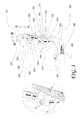
- FIG. 1is perspective view with portions cut away of a motor vehicle having a movable headrest and an occupant sitting on the seat with the headrest adjacent the head of the occupant to provide protection in rear impacts;
- FIG. 2is a perspective view of the rear portion of the vehicle shown in FIG. 1 showing a rear crash anticipatory sensor connected to an electronic circuit for controlling the position of the headrest in the event of a crash;
- FIG. 3is a perspective view of a headrest control mechanism mounted in a vehicle seat and ultrasonic head location sensors consisting of one transmitter and one receiver plus a head contact sensor, with the seat and headrest shown in phantom;
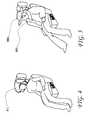
- FIG. 4is a perspective view of a female vehicle occupant having a large hairdo and also showing switches for manually adjusting the position of the headrest;
- FIG. 5is a perspective view of a male vehicle occupant wearing a winter coat and a large hat;
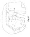
- FIG. 6is view similar to FIG. 3 showing an alternate design of a head sensor using one transmitter and three receivers for use with a pattern recognition system;
- FIG. 7is a schematic view of an artificial neural network pattern recognition system of the type used to recognize an occupant's head
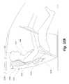
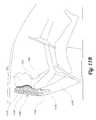
- FIG. 8is a perspective view of an of automatically adjusting head and neck supporting headrest
- FIG. 8Ais a perspective view with portions cut away and removed of the headrest of FIG. 8;
- FIG. 9Ais a side view of an occupant seated in the driver seat of an automobile with the headrest in the normal position
- FIG. 9Bis a view as in FIG. 9A with the headrest in the head contact position as would happen in anticipation of a rear crash;
- FIG. 10Ais a side view of an occupant seated in the driver seat of an automobile having an integral seat and headrest and an inflatable pressure controlled bladder with the bladder in the normal position;
- FIG. 10Bis a view as in FIG. 10A with the bladder expanded in the head contact position as would happen in anticipation of, e.g., a rear crash;
- FIG. 11Ais a side view of an occupant seated in the driver seat of an automobile having an integral seat and a pivotable headrest and bladder with the headrest in the normal position;
- FIG. 11Bis a view as in FIG. 11A with the headrest pivoted in the head contact position as would happen in anticipation of, e.g., a rear crash.
- FIG. 1is perspective view with portions cut away of a motor vehicle, shown generally at 100 , having two movable headrests 110 and 111 and an occupant 150 sitting on the seat with the headrest 110 adjacent a head 151 of the occupant to provide protection in rear impacts.
- FIG. 2a perspective view of the rear portion of the vehicle shown in FIG. 1 is shown with a rear impact crash anticipatory sensor, comprising a transmitter 210 and two receivers 211 and 212 , connected by appropriate electrical connections, e g., wire 220 , to an electronic circuit or control module 250 for controlling the position of the headrest in the event of a crash
- a rear impact crash anticipatory sensorcomprising a transmitter 210 and two receivers 211 and 212 , connected by appropriate electrical connections, e g., wire 220 , to an electronic circuit or control module 250 for controlling the position of the headrest in the event of a crash
- U.S. patent application Ser. No. 09/307,883 filed May 10, 1999an anticipatory sensor system for side impacts is disclosed. This sensor system uses sophisticated pattern recognition technology to differentiate different categories of impacting vehicles.
- a side impact with a large truck at 20 mphis more severe than an impact with a motorcycle at 40 mph, and, since in that proposed airbag system the driver would no longer be able to control the vehicle, the airbag must not be deployed except in life threatening situations. Therefore, it is critical in order to predict the severity of a side impact, to know the type of impacting vehicle.
- the crash sensorwill optimally determine the position and velocity of an approaching object.
- the crash sensorcan be designed to use differences between the transmitted and reflected waves to determine the distance between the vehicle and the approaching object and from successive distance measurements, the velocity of the approaching object.
- the difference between the transmitted and received waves or pulsesmay be reflected in the time of flight of the pulse, a change in the phase of the pulse and/or a Doppler radar pulse, or by range gating an ultrasonic pulse, an optical pulse or a radar pulse.
- the crash sensorcan comprise a radar sensor, a noise radar sensor, a camera, a scanning laser radar and/or a passive infrared sensor.
- FIG. 2therefore, illustrates a simple ranging sensor using a transmitter 210 and two receivers 211 and 212 .
- Transmitter 210may be any wave-generating device such as an ultrasonic transmitter while the receivers 211 , 212 are compatible wave-receiving devices such as ultrasonic receivers.
- the ultrasonic transmitter 210transmits ultrasonic waves
- ECM 250is connected to the electronic control module (ECM) 250 by means of wire 220 , although other possible connecting means (wired or wireless) may also be used in accordance with the invention.
- ECM 250electronice control module
- other configurations of the transmitter 210 , receivers 211 , 212 and ECM 250might be equally or more advantageous.
- the sensorsdetermine the distance of the approaching object and determine its velocity by differentiating the distance measurements or by use of the Doppler effect or other appropriate method.
- an ultrasonic systemis illustrated herein, radar, electromagnetic, e.g., optical, or other systems could also be used as well as any appropriate number of transmitters and receivers.
- the system for determining the location of the head of the occupantcan comprise an electric field sensor, a capacitance sensor, a radar sensor, an optical sensor, a camera, a three-dimensional camera, a passive infrared sensor, an ultrasound sensor, a stereo sensor, a focusing sensor and a scanning system.
- an electric field sensora capacitance sensor
- a radar sensoran optical sensor
- a cameraa three-dimensional camera
- a passive infrared sensoran ultrasound sensor
- stereo sensora focusing sensor and a scanning system.
- pattern recognition systemssuch as neural nets
- neural netsmight not be required, such a system would be desirable.
- other opportunitiesbecome available such as the determination of the nature of objects behind the vehicle. This could be of aid in locating and recognizing objects, such as children, when vehicles are backing up and for other purposes.
- additional transducerssignificantly improve the accuracy of the pattern recognition systems if either ultrasonics or radar systems are used.
- FIG. 3is a perspective view of a headrest actuation mechanism, mounted in a vehicle seat 310 , and transducers 320 , 321 plus a head contact sensor 350 .
- Transducer 320may be an ultrasonic transmitter and transducer 321 may be an ultrasonic receiver.
- the transducers 320 , 321may be based on any type of propagating phenomenon such as electromagnetics (for example capacitive systems), and are not limited to use with ultrasonics.
- the seat 310 and headrest 111are shown in phantom.
- Servomotor 360rotates lead screw 362 which mates with a threaded hole in elongate member 364 causing it to move up or down depending on the direction of rotation of the lead screw 362 .
- Headrest support rods 365 and 366are attached to member 364 and cause the headrest 111 to translate up or down with member 364 . In this manner, the vertical position of the headrest 111 can be controlled as depicted by arrow A—A.
- Wire 332leads from the control module 250 to servomotor 370 which rotates lead screw 372 .
- Lead screw 372mates with a threaded hole in elongate, substantially cylindrical shaft 373 which is attached to supporting structures within the seat shown in phantom.
- the rotation of lead screw 372rotates servo motor support 361 which in turn rotates headrest support rods 365 and 366 in slots 368 and 369 in the seat 310 .
- the headrest 111is caused to move in the fore and aft direction as depicted by arrow B—B.
- arrow B—Bdepicted by arrow B—B.
- the operation of the systemis as follows.
- the transducer 320emits ultrasonic energy which reflects off of the back of the head of the occupant and is received by transducer 321 .
- An electronic circuit containing a microprocessordetermines the distance from the head of the occupant based on the time period between the transmission and reception of an ultrasonic pulse.
- the headrest 111moves up and/or down until it finds the vertical position at which it is closest to the head of the occupant The headrest remains at that position. Based on the time delay between transmission and reception of an ultrasonic pulse, the system can also determine the longitudinal distance from the headrest to the occupant's head.
- the headmay not be located precisely in line with the ultrasonic sensors, or the occupant may be wearing a hat, coat with a high collar, or may have a large hairdo, there may be some error in the longitudinal measurement.
- This problemis solved in an accident through the use of a contact switch 350 on the surface of the headrest. When the headrest contacts a hard object, such as the rear of an occupant's head, the contact switch 350 closes and the motion of the headrest stops.
- the target vehicleWhen a vehicle approaches the target vehicle, the target vehicle containing the headrest and control system of this invention, the time period between transmission and reception of ultrasonic waves, for example, shortens indicating that an object is approaching the target vehicle.
- the approach velocity of the approaching vehiclecan the calculated and a decision made by the circuitry in control module 250 that an impact above a threshold velocity is about to occur.
- the control module 250then sends signals to servo motors 370 and 360 to move the headrest to where it contacts the occupant in time to support the occupant's head and neck and reduce or eliminate a potential whiplash injury as explained in more detailed below.
- the seatalso contains two switch assemblies 380 and 382 for controlling the position of the seat 310 and headrest 111 .
- the headrest control switches 382permit the occupant to adjust the position of the headrest in the event that the calculated position is uncomfortably close to or far from the occupant's head A woman with a large hairdo might find that the headrest automatically adjusts so as to contact her hairdo. This might be annoying to the woman who could then position the headrest further from her head.
- the position of the headrest relative to the occupant's headcan also be recorded.
- an automatic adjustmentresults which moves the headrest to each specific occupant's desired and memorized headrest position.
- the identification of the specific individual occupant for which memory look-up or the like would occurcan be by height sensors, weight sensors (for example placed in a seat), or by pattern recognition means, or a combination of these and other means, as disclosed in the above-referenced patent applications and granted patents.
- This systemmoves the headrest toward the occupant's head until it senses a resistance characteristic of the occupant's head
- the systemwill not be fooled by a high coat collar 501 or hat 502 , as illustrated in FIG. 5, or other article of clothing or by a large hairdo 401 as illustrated in FIG. 4 .
- the headrestcontinues to be moved until it contacts something relatively rigid as determined by the contact switch 350 .
- a key advantage of this systemis that there is no permanent damage to the system when it deploys during an accident. After the event it will reset without an expensive repair. In fact, it can be designed to reset automatically.
- An ultrasonic sensor in the headresthas previously been proposed in a U.S. patent to locate the occupant for the out-of-position occupant problem. In that system, no mention is made as to how to find the head.
- the headrestIn the headrest location system described herein, the headrest can be moved up and down in response to the instant control systems to find the location of the back of the occupant's head. Once it has been found the same sensor is used to monitor the location of the person's head. Naturally, other methods of finding the location of the head of an occupant are possible.
- FIG. 6is view similar to FIG. 3 showing an alternate design of a head sensor using three transducers 320 , 321 and 322 for use with a pattern recognition system.
- Transducer 320performs both as a transmitter and receiver while transducers 321 , 322 perform only as receivers
- Transducers 321 , 322are placed on either side of transducer 320 and above the same.
- the systemwould be trained for a wide variety of different cases prior to installation into the vehicle This training is accomplished by placing a large variety of different occupants onto the driver's seat in a variety of different positions and recording digitized data from transducers 320 , 321 and 322 along with data representing the actual location of the occupant's head.
- the different occupantsinclude examples of large and small people, men and women, with many hair, hat, and clothing styles.
- the total data setcalled the “training set”
- This training setis then used to train the neural network, or other similar trainable pattern recognition technology, so that the resulting network can locate the occupant's head in the presence of the types of obstructions discussed above whatever an occupant occupies the driver's seat.
- FIG. 7is a schematic view of an artificial neural network of the type used to recognize an occupant's head.
- the theory of neural networksincluding many examples can be found in several books on the subject including: Techniques And Application Of Neural Networks, edited by Taylor, M. and Lisboa, P., Ellis Horwood, Westshire, England, 1993; Naturally Intelligent Systems, by Caudill, M. and Butler, C., MIT Press, Cambridge Mass., 1990; and, Digital Neural Networks, by Kung, S. Y., PTR Prentice Hall, Englewood Cliffs, N.J., 1993. the neural network is presented here as an example of a pattern recognition technology. Other pattern recognition algorithms, such as neural-fuzzy systems, are being developed which, in some cases, have superior performance to pure neural networks.
- the process of locating the head of an occupantcan be programmed to begin when an event occurs such as the closing of a vehicle door or the shifting of the transmission out of the PARK position.
- the ultrasonic transmitting/receiving transducer 320transmits a train of ultrasonic waves toward the head of the occupant Waves reflected from the occupant's head are received by transducers 320 , 321 and 322 .
- An electronic circuit containing an analog to digital converterconverts the received analog signal to a digital signal which is fed into the input nodes numbered 1 , 2 , 3 , . . . n, shown on FIG. 7 .
- the neural network algorithmcompares the pattern of values on nodes 1 through N with patterns for which it has been trained, as discussed above.
- Each of the input nodesis connected to each of the second layer nodes, called the hidden layer, either electrically as in the case of a neural computer or through mathematical functions containing multiplying coefficients called weights, described in more detail below.
- the weightsare determined during the training phase while creating the neural network as described in detail in the above text references.
- At each hidden layer nodea summation occurs of the values from each of the input layer nodes, which have been operated on by functions containing the weights, to create a node value.
- the hidden layer nodesare in like manner connected to the output layer nodes, which in this example is only a single node representing the longitudinal distance to the back of the occupant's head.
- the distance to the occupant's head for a large variety of patternsis taught to the system These patterns include cases where the occupant is wearing a hat, has a high collar, or a large hairdo, as discussed above, where a measurement of the distance to the back of the occupant's head cannot be directly measured
- the neural networkrecognizes a pattern similar to one for which it has been trained, it then knows the distance to the occupant's head. The details of this process are described in the above listed referenced texts and will not be presented in detail here.
- the neural network pattern recognition system described hereinis one of a variety of pattern recognition technologies which are based on training.
- the neural networkis presented herein as one example of the class of technologies referred to as pattern recognition technologies.
- Ultrasonicsis one of many technologies including optical, infrared, capacitive, radar, or other electromagnetic based technologies Although the reflection of waves was illustrated, any modification of the waves by the head of the occupant is anticipated including absorption, capacitance change, phase change, transmission and reemission. Additionally, the radiation emitted from the occupant's head can be used directly without the use of transmitted radiation Naturally, combinations of the above technologies can be used
- a time stepsuch as one tenth of a millisecond, is chosen as the period at which the analog to digital converter (ADC) averages the output from the ultrasonic receivers and feeds data to the input nodes.
- ADCanalog to digital converter
- the input to each input nodeis a preprocessed combination of the data from the three receivers.
- separate input nodeswould be used for each transducer.
- the input data to the nodescan be the result of a preprocessing algorithm which combines the data taking into account the phase relationships of the three return signals to obtain a map or image of the surface of the head using the principles of phased array radar.
- one hundred input nodes, twelve hidden layer nodes and one output layer nodeare typically used. In this example received data from only three receivers were considered. If data from additional receivers is also available the number of input layer nodes could increase depending on the preprocessing algorithm used. If the same neural network is to be used for sensing rear impacts, one or more additional output nodes might be used, one for each decision.
- the theory for determining the complexity of a neural network for a particular applicationhas been the subject of many technical papers as well as in the texts referenced above and will not be presented in detail here. Determining the requisite complexity for the example presented here can be accomplished by those skilled in the art of neural network design and is discussed briefly below.
- the pattern recognition system described abovedefines a method of determining the probable location of the rear of the head of an occupant and, will therefore determine, if used in conjunction with the anticipatory rear impact sensor, where to position a deployable occupant protection device in a rear collision, and comprises the steps of:
- neural networkcontains a single series of hidden layer nodes In some network designs, more than one hidden layer is used although only rarely will more than two such layers appear.
- neural networkwill be defined as a system wherein the data to be processed is separated into discrete values which are then operated on and combined in at least a two stage process and where the operation performed on the data at each stage is in general different for each of the discrete values and where the operation performed is at least determined through a training process.
- the operation performedis typically a multiplication by a particular coefficient or weight and by different operation, therefore is this example, a different weight is used for each discrete value.
- neural networkscan take at least two forms, an algorithm programmed on a digital microprocessor or in a neural computer.
- Neural computer chipsare just now becoming available and are beyond the price range of commercially acceptable head sensing applications at this time, however, the prices are expected to drop soon.
- the neural networkis typically trained using data from 1000 or more than 100,000 different combinations of people, clothes, wigs etc. There are, of course, other situations which have not been tested. As these are discovered, additional training will improve the performance of the pattern recognition head locator.
- a pattern recognition systemis implemented in a vehicle, the same system can be used for many other pattern recognition functions as described in the above referenced patents and patent applications.
- the use of neural networks as a preferred pattern recognition technologyis disclosed for use in identifying a rear facing child seat located on the front passenger seat of an automobile.
- This same patent applicationalso discloses many other applications of pattern recognition technologies for use in conjunction with monitoring the interior of an automobile passenger compartment.
- whiplash injuriestypically occur when there is either no head support or when only the head of the occupant is supported during a rear impact. To minimize these injuries, both the head and neck should be supported.
- the head and neckare supported through a pivoting headrest which first contacts the head of the occupant and then rotates to simultaneously support both the head and the neck. The force exerted by the head and neck onto the pivoting headrest is distributed based on the relative masses of the head and neck.
- Dellannoassumes that the ratio of these masses is substantially the same for all occupants and that the distances between centers of mass of the head and neck is approximately also proportional for all occupants To the extent that this is not true, a torque will be applied to the headrest and cause a corresponding torque to be applied to the head and neck of the occupant. Ideally, the head and neck would be supported with just the required force to counteract the inertial force of each item. Obviously this can only approximately be accomplished with the Dellanno pivoting headrest especially when one considers that no attempt has been made to locate the headrest relative to the occupant and the proper headrest position will vary from occupant to occupant. Dellanno also assumes that the head and neck will impact and in fact bounce off of the headrest A far more significant improvement to eliminating whiplash injuries can be accomplished by eliminating this head impact and the resulting rebound as is accomplished in the present invention.
- Automobile engineersattempt to design vehicle structures so that in an impact the vehicle is accelerated at an approximately constant acceleration. It can be shown that this results in the most efficient use of the vehicle structure in absorbing the crash energy. It also minimizes the damage to the vehicle in a crash and thus the cost of repair. Let us assume, therefore, that in a particular rear impact that the vehicle accelerates at a constant 15 g acceleration. Let us also assume that the vehicle seat back is rigidly attached to the vehicle structure at least during the early part of the crash, so that up until shortly after the occupant's head has impacted the headrest the seat back also is accelerating at a constant 15 g's. Finally let us assume that the occupant's head is initially displaced 4 inches from the headrest and that during impact the head compresses the headrest 1 inch.
- the Dellanno headrestas shown for example in FIG. 3 of U.S. Pat. No. 5,290,091, is a worthwhile addition to solving the whiplash problem after the headrest has been positioned against the head and neck of the occupant.
- FIG. 8illustrates a headrest design which accomplishes the objectives of the Dellanno headrest in a far simpler structure and at less potential injury to the occupant.
- FIG. 8a seat with a movable headrest similar to the one illustrated in FIG. 3 is shown with a headrest designated 800 designed to provide support to both the head and neck which eliminates the shortcomings of the Dellanno headrest.
- the ultrasonic transducer 320which includes both a transmitter and receiver, has been moved to an upper portion of the seat back, not the headrest, to facilitate the operation of the support system as described below.
- the construction of the headrestis illustrated in a cutaway view shown in FIG. 8A which is an enlarged view of the headrest of FIG. 8 .
- the headrestis constructed of a support or frame 805 which is attached to rods 812 and extends along the sides and across the back of the headrest.
- Support 805may be made of a somewhat rigid material. This support 805 helps control the motion of a pre-inflated bag 815 as it deforms under the force from the head of the occupant to where it contacts and provides support to the occupant's neck.
- Relatively low density open cell foam 840surrounds the support 805 giving shape to the remainder of the headrest.
- the open call foam 840can also have channels or openings 842 extending in a direction generally from a top of the headrest 800 to a bottom of the headrest 800 , although such channels are not required.
- the direction of the channels or openings 842facilitates the desired movement of the fluid in the bag 815 and constrains the fluid flow upon impact of the occupant's head against the headrest 800 , i.e, a generally vertical movement in the case of the illustrated headrest 800 .
- the open call foam 840is covered by a thin membrane, possibly made from plastic, or the bag 815 (also referred to as an airbag herein which is appropriate when the fluid in the bag 815 is air-although the fluid within bag 815 may be other than air), and by a decorative cover 810 made of any suitable, acceptable material.
- the bag 815is sealed surrounding the support 805 and plastic foam 840 such that any flow of fluid such as air into or out of the bag 815 is through a hole in the bag 815 adjacent to a vent hole 844 in the supporting structure, i.e., the cover 810
- Elastic stretch seams 812are placed in the sides, bottom and/or across the front of the headrest cover to permit the headrest surface to deform to the contour of, and to properly support, the occupant's head and neck.
- a contact switch 850is placed just inside cover 810 and functions as described above.
- the properties of the foamcan be selected to provide the desired flow of gas, e.g, the design, shape, positioning and construction of the foam can be controlled and determined during manufacture to obtain the desired flow properties.
- FIG. 9 A and FIG. 9Billustrate the operation of the headrest 800 .
- headrest 800In anticipation of a rear impact (or any other type of impact), as determined by the proximity sensors described above or any other anticipatory crash sensor system, headrest 800 is moved from its position as shown in FIG. 9A to its position as shown in FIG. 9 B. This movement is enabled by control of the displacement means, such as those described above with reference to FIG. 3, as effected through the control module 250 .
- the forward movement of the headrest 800should continue until the headrest 800 contacts or impacts with the occupant's head as determined by a contact switch 850
- headrest 800contacts or impacts the head 910 of the occupant 900
- This initial flow of airtakes place as the foam 840 compresses under the force of contact between the head and upper portion 920 of headrest 800 .
- headrest 800is created by the shape of the foam 840 ; however once the occupants head 910 begins to exert pressure on the upper portion 920 the air is compressed and begins to flow to the lower portion 930 causing it to expand until it contacts the neck 915 of the occupant 900 .
- the headrest of this inventionacts very much like a pre-inflated airbag providing force where force is needed to counteract the accelerations of the occupant. It accomplishes this force balancing without the need to rotate a heavy object such as the headrest in the Dellanno patent which by itself could introduce injuries to the occupant.
- the structure described abovecan be used in other applications for cushioning an occupant of a vehicle, i.e., for cushioning another part of the occupant's body in an impact
- the cushioning arrangementwould thus comprise a frame or support coupled to the vehicle and a fluid-containing bag attached to the frame or other support.
- a deformable coverwould also be preferred.
- the bag, including the cell foam and vent hole as described above,would allow movement of the fluid within the bag to thereby alter the shape of the bag, upon contact with the part of the occupant's body, and enable the bag to conform to the part of the occupant's body. This would effectively cushion the occupant's body during an impact.
- cushioning arrangementcould be coupled to the anticipatory crash sensor through a control unit (i.e., control module 250 ) and displacement means in a similar manner as headrest 800 , to thereby enable movement of the cushioning arrangement against the part of the occupant's body just prior to or coincident with the crash.
- control uniti.e., control module 250
- displacement meansin a similar manner as headrest 800
- FIG. 9 of U.S. Pat. No. 5,098,124 to Breed et al.which is incorporated herein by reference.
- the headrest disclosed herediffers primarily through the use of a single pre-inflated fluid-containing bag, fluid-filled bag or airbag which when impacted by the head of the occupant, deforms by displacing the surface of the headrest outwardly to capture and support the neck of the occupant.
- the use of an airbag to prevent whiplash injuriesis common for accidents involving frontal impacts and driver and passenger side airbags.
- This pre-inflated airbag headresthas another feature which further improves its performance.
- the vent hole 844is provided to permit some of the air in the headrest to escape in a controlled manner thereby dampening the motion of the head and neck much in the same way that a driver side airbag has vent holes to dissipate the energy of the impacting driver during a crash.
- Appropriate regulation meansmay also be associated with the vent hole 844 of the headrest 800 to regulate the escaping air. Without the vent hole, there is risk that the occupant's head and neck will rebound off of the headrest, as is also a problem in the Dellanno patents.
- the size of this holeis determined experimentally or by mathematical analysis and computer simulation. If it is too large, too much air will escape and the headrest will bottom out on the support. If it is too small, the head will rebound off of the headrest thereby increasing the chance of whiplash injury. Naturally, a region of controlled porosity could be substituted for hole 844 .
- a side benefit of this inventionis that it can be used to determine the presence of an occupant on the front passenger seat. This information can then be used to suppress deployment of an airbag if the seat is unoccupied.
- FIG. 10Ais a side view of an occupant seated in the driver seat of an automobile having an integral seat and headrest and an inflatable pressure controlled bladder with the bladder in the normal, uninflated condition.
- FIG. 10Bis a view as in FIG. 10A with the bladder expanded in the head contact position as would happen in anticipation of, e.g, a rear crash.
- the seat containing the bladder system of this embodiment of the inventionis shown generally at 1000 .
- the seat 1000contains an integral bladder 1030 arranged within the cover of the seat 1000 , a fluid-containing chamber 1020 connected to the bladder 1030 and a small igniter assembly 1010 , which contains a small amount, such as about 5 grams, of a propellant such as barium potassium nitrate.
- igniter assembly 1010Upon receiving a signal that a crash is imminent, igniter assembly 1010 is ignited and supplies a small quantity of hot propellant gas into chamber 1020 .
- the gas (the fluid in a preferred embodiment) in chamber 1020then expands due to the introduction of the high temperature gas and causes the bladder 1030 to expand to the condition shown in FIG. 10 B.
- Bladder 1030expands in such a manner (through its design, construction and/or positioning and/or through the design and construction of the seat 1000 ) as to conform to the shape of the occupant's head 910 and neck 915 .
- pressurebegins to increase in the bladder 1030 causing a control valve 1050 to open and release gas into the passenger compartment to thereby prevent the occupant from being displaced toward the front of the vehicle
- Control valve 1050is situated in a flow line between the bladder 1030 and an opening in the rear of the seat 1000 in the illustrated embodiment, but may be directly connected to the bladder 1030 .
- the flow linemay be directed to another location, e.g., the exterior of the vehicle, through appropriate conduits.
- Control valve 1050can be controlled by appropriate control means, such as the central diagnostic module, and the amount of gas released coordinated with or based on the severity of the crash or any other parameter of the crash or deployment of the airbag.
- the igniter assembly 1010may be positioned so that it can be readily accessed from the rear of the seat, e.g., by removing a panel in the rear of the seat.
- the igniter assembly 1010may be coupled directly or indirectly to a crash sensor, possibly through a central diagnostic module of the vehicle.
- the crash sensoris preferably an anticipatory crash sensor arranged so as to detect rear impacts because whiplash injuries are mostly caused during rear impacts.
- the crash sensordetects the impending crash into the rear of the vehicle and generates a signal or causes a signal to be generated indicative of the fact that the igniter assembly 1010 should be activated to inflate the bladder 1030 .
- the igniter assembly 1010is then activated generating heated gas which is directed into chamber 1020 .
- the gas in chamber 1020expands and passes through one or more conduits into the bladder 1030 causing the bladder 1030 to expand to the condition shown in FIG. 10 B.
- the expanding bladder 1030will fill in the space between the occupant and the headrest and seat as shown in FIG. 10 B.
- the bladder 1030may be designed to have more expansion capability in the head and neck areas as those surfaces will initially be further from the body of the driver. The inflated bladder 1030 will thus reduce the risk of whiplash injuries to the driver.
- the control valve 1050is designed or controlled to ensure that the bladder 1030 expands sufficiently to provide whiplash protection without exerting a forward force of the driver.
- the pressure in the bladder 1030may be measured during inflation and once it reaches an optimum level, the control (or pressure release) valve 1050 may be activated.
- the time it takes for the bladder 1030 to inflate to the optimum levelmay be computed and then the control valve 1050 designed to activated after this predetermined time.
- the igniter assembly 1010can be removed and replaced with compatible igniter assembly so that the vehicle is ready for subsequent use.
- the bladder 1030is integral with the seat 1000 and the headrest of the seat is formed with the backrest as a combined seat back portion. If the headrest is formed separate from the backrest, then the bladder 1030 can be formed integral with the headrest and if necessary, integral with the backrest to achieve the whiplash protection sought by the invention.
- FIG. 11Ais a side view of an occupant seated in the driver seat of an automobile having an integral seat and a pivotable or rotatable headrest and bladder with the headrest in the normal position.
- FIG. 11Bis a view as in FIG. 11A with the headrest pivoted in the head contact position as would happen in anticipation of, e.g., a rear crash. in contrast to the embodiment of FIGS. 10A and 10B, this embodiment is purely passive in that no pyrotechnics are used.
- electronic circuitry 1115activates solenoid 1130 causing headrest portion 1110 to rotate about pivot 1140 (an axis, pin, etc) toward the occupant.
- the systemis shown generally at 1100 and comprises a seat back portion 1120 and headrest portion 1110 .
- the headrest portion 1110has rotated until it contacts the occupant and then a bladder or airbag 1150 within headrest portion 1110 changes shape or deforms to conform to the head 910 and neck 915 of the occupant thereby supporting both the head and neck and preventing a whiplash injury.
- the control of the rotation of the headrest portion 1110can be accomplished either by a contact switch or force measurement using a switch or force sensor in the headrest or a force or torque sensor at the solenoid 1130 or, alternately, by measuring the pressure within the airbag 1150 .
- Solenoid 1130can be replaced by another linear actuator such as an air cylinder with an appropriate source of air pressure.
- the electronic circuitry 1115may be controlled by the central diagnostic module or upon receiving a signal from the crash sensor Airbag 1150 is shown arranged within the headrest portion 1110 , i.e., it is within the periphery of the surface layer of the headrest portion 1110 and seat 1100 .
- the crash sensordetects the impending crash, e.g., into the rear of the vehicle, and generates a signal or causes a signal to be generated resulting in pivotal movement of the headrest portion 1110 .
- the headrest portion 1110is moved (pivoted) preferably until a point at which the front of the headrest portion 1110 touches the back of the driver's head. This can all occurs prior to the actual crash. Thereafter, upon the crash, the driver will be forced backwards against the pivoted headrest portion 1110 . Gas will flow from the upper part of the headrest portion 1110 and the seat back and thereby distribute the load between the head, neck and body.
- the headrest portion of the seatis formed with the backrest as a combined seat back portion. If the headrest is formed separate from the backrest, then the airbag 1150 can be formed integral with the headrest and if necessary, integral with the backrest to achieve the whiplash protection sought by the invention. In this case, the pivot 1140 might be formed in the backrest or between the backrest and headrest.
- the same systemscould be used for passengers in the vehicle as well, i.e., it could be used for the front-seat passenger(s) and any rear-seated passengers. Also, although whiplash injuries are most problematic in rear impacts, the same system could be used for side impacts as well as front impacts and rollovers with varying degrees of usefulness.
- a seat for a vehicle for protecting an occupant of the seat in a crashwhich comprises a headrest portion, an expandable bladder arranged at least partially in the headrest portion, the bladder being arranged to conform to the shape of a neck and head of the occupant upon expansion, and an igniter for causing expansion of the bladder upon receiving a signal that protection for the occupant is desired.
- the bladdermay also be arranged in least partially in the backrest portion of the seat.
- a fluid-containing chamberis coupled to the igniter and in flow communication with the bladder whereby the igniter causes fluid in the chamber to expand and flow into the bladder to expand the bladder.
- a control valveis associated with the bladder for enabling the release of fluid from the bladder.
- the bladderis preferably arranged in an interior of the headrest portion, i.e., such that its expansion is wholly within the outer surface layer of the headrest portion of the seat
- a vehicle including this systemcan also include a crash sensor system for determining that a crash requiring protection for the occupant is desired.
- the crash sensor systemgenerates a signal and directing the signal to the igniter.
- the crash sensor systemmay be arranged to detect a rear impact.
- Another seat for a vehicle for protecting an occupant of the seat in a crash disclosed abovecomprises a backrest including a backrest portion and a headrest portion and an airbag arranged at least partially in the headrest portion.
- the headrest portionis pivotable with respect to the backrest portion toward the occupant.
- pivot meansare provide for enabling pivotal movement of the headrest portion relative to the backrest portion.
- the pivot meansmay be a solenoid arranged to move an arm about a pivot axis, which arm is coupled to the headrest portion.
- the airbagis arranged in an interior of the headrest portion of the backrest.
- a vehicle including this systemcan also include a crash sensor system for determining that a crash requiring protection for the occupant is desired.
- the headrest portionis pivoted into contact with the occupant upon a determination by the crash sensor system that a crash requiring protection for the occupant is desired.
- the crash sensor systemmay be arranged to detect a rear impact.
- a headrest for a seatwhich comprises a frame attachable to the seat and a fluid-containing bag attached to the frame.
- the bagis structured and arranged to allow movement of the fluid within the bag to thereby alter the shape of the bag and enable the bag to conform to the head and neck of an occupant.
- a deformable covermay substantially surround the bag such that the bag is within the seat, i.e., an outer surface of the bag is not exposed to the atmosphere.
- the coveris elastically deformable in response to changes in pressure in the bag.
- the framemay be made of a rigid material.
- the bagcan contain cell foam having openings (open cell foam), which in a static state, determines the shape of the bag.
- the fluid in the bagmay be air, i e., an airbag.
- the covermay include stretch seams at one or more locations.
- the stretch seamsshould be placed on the side(s) of the headrest which will contour to the shape of the occupant's head and neck upon impact.
- the bagmay include constraining means for constraining flow of fluid from an upper portion of the headrest to a lower portion of the headrest.
- constraining meansmay comprise open cell foam possibly with channels extending in a direction from a top of the headrest to a bottom of the headrest.
- the properties of the foammay be controlled to get the desired flow rate and possibly flow direction.
- the constraining meansare structured and arranged such that when the upper portion contracts, the lower portion expands.
- the constraining meansmay be designed so that when the upper portion expands, the lower portion contracts.
- the cover and bagare structured and arranged such that when an occupant impacts the headrest, fluid within the bag flows substantially within the bag to change the shape of the bag so as to approximately conform to the head and neck of the occupant thereby providing a force on the head and neck of the occupant to substantially accelerate both the head and neck at substantially the same acceleration in order to minimize whiplash injuries.
- the bagpreferably includes a flow restriction which permits a controlled flow of fluid out of the bag upon impact of an object with the headrest to thereby dampen the impact of the object with the headrest.
- An inventive seatcomprises a seat frame, a bottom cushion, a back cushion cooperating to support an occupant and a headrest attached to the seat frame.
- the headrestis as in any of the embodiments described immediately above.
- An inventive cushioning arrangement for protecting an occupant in a crashcomprises a frame coupled to the vehicle and a fluid-containing bag attached to the frame.
- the bagis structured and arranged to allow movement of the fluid within the bag to thereby alter the shape of the bag and enable the bag to conform to a portion of the occupant engaging the cushioning arrangement.
- the cushioning arrangementshould be arranged relative to the occupant such that the bag impacts the occupant during the crash.
- impactdoes not necessarily imply direct contact between the occupant and the bag but rather may be considered the exertion of pressure against the bag caused by contact of the occupant with the outer surface of the cushioning arrangement which is transmitted to the bag.
- the cushioning arrangementcan also include a deformable cover substantially surrounding the bag.
- the coveris elastically deformable in response to changes in pressure in the bag.
- the framemay be coupled to a seat of the vehicle and extends upward from a top of the seat such that the cushioning arrangement constitutes a headrest.
- the cushioning arrangementcan be used anywhere in a vehicle in a position in which the occupant will potentially impact it during the crash
- the bag and headrestmay be as in any of the embodiments described above.
- An inventive protection system for protecting an occupant in a crashcomprises an anticipatory crash sensor for determining that a crash involving the vehicle is about to occur, and a movable cushioning arrangement coupled to the anticipatory crash sensor.
- the cushioning arrangementis movable toward a likely position of the occupant, preferably in actual contact with the occupant, upon a determination by the anticipatory crash sensor that a crash involving the vehicle is about to occur.
- the cushioning arrangementcomprises a frame coupled to the vehicle, and a fluid-containing bag attached to the frame.
- the bagis structured and arranged to allow movement of the fluid within the bag to thereby alter the shape of the bag and enable the bag to conform to the occupant.
- the cushioning arrangement and its partsmay be as described in any of the embodiments above.
- the anticipatory crash sensormay be arranged to determine that the crash involving the vehicle is a rear impact.
- itcould comprise a transmitter/receiver arrangement mounted at the rear of the vehicle.
- a displacement mechanismis provided, e.g., a system of servo-motors, screws and support rods, and a control unit is coupled to the anticipatory crash sensor and the displacement mechanism. The control unit controls the displacement mechanism to move the cushioning arrangement based on the determination by the anticipatory crash sensor that a crash involving the vehicle is about to occur.
- One disclosed method for protecting an occupant in an impactcomprises the steps of determining that a crash involving the vehicle is about to occur, and moving a cushioning arrangement into contact with the occupant upon a determination that a crash involving the vehicle is about to occur.
- the cushioning arrangementcomprises a frame coupled to the vehicle and a fluid-containing bag attached directly or indirectly to the frame.
- the bagis structured and arranged to allow movement of the fluid within the bag to thereby alter the shape of the bag and enable the bag to conform to the occupant.
- the cushioning arrangementmay be as in any of the embodiments described above.
- the step of moving the cushioning arrangement into contact with the occupantmay comprise the steps of moving the cushioning arrangement toward the occupant, detecting when the cushioning arrangement comes into contact with the occupant and then ceasing movement of the cushioning arrangement.
- the step of detecting when the cushioning arrangement comes into contact with the occupantmay comprise the step of arranging a contact switch in connection with the cushioning arrangement.
- a headrest and headrest positioning systemwhich reduce whiplash injuries from rear impacts by properly positioning the headrest behind the occupant's head either continuously, or just prior to and in anticipation of, the vehicle impact and then properly supports both the head and neck.
- Sensorsdetermine the location of the occupant's head and motors move the headrest both up and down and forward and back as needed.
- the headrestis continuously adjusted to maintain a proper orientation of the headrest to the rear of the occupant's head.
- an anticipatory crash sensorsuch as described in U S. patent application Ser. No. 09/307,883, is used to predict that a rear impact is about to occur, in which event, the headrest is moved proximate to the occupant.
- an apparatus for determining the location of the head of the occupant in the presence of objects which obscure the headcomprises transmitter means for illuminating a selective portion of the occupant and the head-obscuring objects in the vicinity of the head, sensor means for receiving illumination reflected from or modified by the occupant and the head-obscuring objects and generating a signal representative of the distance from the sensor means to the illuminated portion of the occupant and the head-obscuring objects, selective portion changing means for changing the illuminated portion of the occupant and the head-obscuring objects which is illuminated by the transmitter means and a processor.
- the processorcomprises means for sequentially operating the selective portion changing means so as to illuminate different portions of the occupant and the head-obscuring objects, and pattern recognition means for determining the location of the head from the signals representative of the distance from the sensor means to the different selective portions of the occupant and the head-obscuring objects
- the pattern recognition meansmay comprise a neural network.
- the head-obscuring objectscomprise items from the class containing clothing and hair.
- the pattern recognition meansmay be arranged to determine the location of the approximate longitudinal location of the head from the headrest. If one or more airbags is mounted within the vehicle, the head location system may include means for determining the location of the head relative to the airbag.
- the transmitter meansmay comprise an ultrasonic transmitter arranged in the headrest and the sensor means may also be arranged in the headrest, possibly vertically spaced from the transmitter means.
- the transmitter means and sensor meansmay comprise a single transducer.
- the selective portion changing meansmay comprise a control module coupled to the transmitter means and the sensor means and servomotors for adjusting the position of the headrest.
- Illumination as used hereinis any form of radiation which is introduced into a volume of which contains the head of an occupant and includes, but it is not limited to, electromagnetic radiation from below one kHz to above ultraviolet optical radiation (10 16 Hz) and ultrasonic radiation.
- any systemsuch as a capacitive system, which uses a varying electromagnetic field, or equivalently electromagnetic waves, is meant to be included by the term illumination as used herein.
- reflected radiationit is meant the radiation that is sensed by the device that comes from the volume occupied by the head, or other part, of an occupant and indicates the presence of that part of the occupant.
- ultrasonic transmitters and receiversplaced in the headrest of the vehicle seat, capacitive sensors placed in the headrest or other appropriate location (or a combination of locations such as one plate of the capacitor being placed in the vehicle seat and the other in the headliner), radar, far or near frequency infrared, visible light, ultraviolet, etc.
Landscapes
- Engineering & Computer Science (AREA)
- Mechanical Engineering (AREA)
- Aviation & Aerospace Engineering (AREA)
- Transportation (AREA)
- Air Bags (AREA)
- Seats For Vehicles (AREA)
Abstract
Description
Claims (61)
Priority Applications (7)
| Application Number | Priority Date | Filing Date | Title |
|---|---|---|---|
| US10/234,063US6746078B2 (en) | 1997-12-17 | 2002-09-03 | System and method for moving a headrest based on anticipatory sensing |
| US10/733,957US7243945B2 (en) | 1992-05-05 | 2003-12-11 | Weight measuring systems and methods for vehicles |
| US10/895,121US7407029B2 (en) | 1992-05-05 | 2004-07-21 | Weight measuring systems and methods for vehicles |
| US11/381,001US7604080B2 (en) | 1997-12-17 | 2006-05-01 | Rear impact occupant protection apparatus and method |
| US11/924,690US7695015B2 (en) | 1997-12-17 | 2007-10-26 | Rear impact occupant protection apparatus and method |
| US11/924,734US7588115B2 (en) | 1997-12-17 | 2007-10-26 | System and method for moving a headrest for whiplash prevention |
| US12/039,427US7660437B2 (en) | 1992-05-05 | 2008-02-28 | Neural network systems for vehicles |
Applications Claiming Priority (3)
| Application Number | Priority Date | Filing Date | Title |
|---|---|---|---|
| US08/992,525US6088640A (en) | 1997-12-17 | 1997-12-17 | Apparatus for determining the location of a head of an occupant in the presence of objects that obscure the head |
| US09/613,925US6805404B1 (en) | 1997-12-17 | 2000-07-11 | Vehicular seats including occupant protection apparatus |
| US10/234,063US6746078B2 (en) | 1997-12-17 | 2002-09-03 | System and method for moving a headrest based on anticipatory sensing |
Related Parent Applications (2)
| Application Number | Title | Priority Date | Filing Date |
|---|---|---|---|
| US09/613,925Continuation-In-PartUS6805404B1 (en) | 1992-05-05 | 2000-07-11 | Vehicular seats including occupant protection apparatus |
| US10/234,436Continuation-In-PartUS6757602B2 (en) | 1992-05-05 | 2002-09-03 | System for determining the occupancy state of a seat in a vehicle and controlling a component based thereon |
Related Child Applications (2)
| Application Number | Title | Priority Date | Filing Date |
|---|---|---|---|
| US10/733,957Continuation-In-PartUS7243945B2 (en) | 1982-06-18 | 2003-12-11 | Weight measuring systems and methods for vehicles |
| US10/895,121Continuation-In-PartUS7407029B2 (en) | 1992-05-05 | 2004-07-21 | Weight measuring systems and methods for vehicles |
Publications (2)
| Publication Number | Publication Date |
|---|---|
| US20030015898A1 US20030015898A1 (en) | 2003-01-23 |
| US6746078B2true US6746078B2 (en) | 2004-06-08 |
Family
ID=27087118
Family Applications (1)
| Application Number | Title | Priority Date | Filing Date |
|---|---|---|---|
| US10/234,063Expired - LifetimeUS6746078B2 (en) | 1992-05-05 | 2002-09-03 | System and method for moving a headrest based on anticipatory sensing |
Country Status (1)
| Country | Link |
|---|---|
| US (1) | US6746078B2 (en) |
Cited By (49)
| Publication number | Priority date | Publication date | Assignee | Title |
|---|---|---|---|---|
| US20050024501A1 (en)* | 1996-05-22 | 2005-02-03 | John Ellenby | Method and apparatus for controlling the operational mode of electronic devices in response to sensed conditions |
| US20050121885A1 (en)* | 2003-12-05 | 2005-06-09 | Elesys North America, Inc. | Vehicle occupant sensing system |
| US20050264051A1 (en)* | 2004-05-26 | 2005-12-01 | Lawall Jennifer P | Occupant detecting seat assembly with headrest and method of moving headrest |
| US20060001308A1 (en)* | 2004-06-30 | 2006-01-05 | Lear Corporation | Vehicle seat having a moveable head restraint |
| US20060042851A1 (en)* | 2004-09-02 | 2006-03-02 | Thomas Herrmann | Passenger-protection device in a vehicle |
| US20060138817A1 (en)* | 2004-12-29 | 2006-06-29 | Gorman Patrick J | Energy absorbing seat recliner assembly |
| US20060163930A1 (en)* | 2004-12-28 | 2006-07-27 | Pettersson Erik O | Head restraint system |
| US20060170271A1 (en)* | 2004-06-16 | 2006-08-03 | Coccoli Oreste M | Pneumatically positioned headrest |
| US20060175881A1 (en)* | 2004-12-28 | 2006-08-10 | Fumitoshi Akaike | Head rests |
| US20060186713A1 (en)* | 1997-12-17 | 2006-08-24 | Automotive Technologies International, Inc. | Rear Impact Occupant Protection Apparatus and Method |
| US20060226686A1 (en)* | 2005-03-22 | 2006-10-12 | Shihong Yu | Spinal protection system for automotive seat |
| US20060226688A1 (en)* | 2005-03-23 | 2006-10-12 | Aisin Seiki Kabushiki Kaisha | Headrest |
| US20060253241A1 (en)* | 2003-02-07 | 2006-11-09 | Hans-Dieter Bothe | Device for adjusting at least one vehicle seat |
| US20060279114A1 (en)* | 2004-11-26 | 2006-12-14 | Toda Shigeyoshi | Head rests |
| US20070024096A1 (en)* | 2005-07-27 | 2007-02-01 | Aisin Seiki Kabushiki Kaisha | Vehicle seat slide device |
| US20070052265A1 (en)* | 2005-08-25 | 2007-03-08 | Aisin Seiki Kabushiki Kaisha | Headrest apparatus for vehicle |
| US20070176473A1 (en)* | 2006-01-30 | 2007-08-02 | Aisin Seiki Kabushiki Kaisha | Headrest control apparatus for vehicle and method of controlling headrest control apparatus for vehicle |
| US20070246979A1 (en)* | 2006-04-17 | 2007-10-25 | Gm Global Technology Operations, Inc. | Active material actuated headrest assemblies |
| US20070257528A1 (en)* | 2004-01-30 | 2007-11-08 | Fumitoshi Akaike | Head Rest Control Device and Active Head Rest |
| US20080030061A1 (en)* | 2006-08-04 | 2008-02-07 | Srinivas Pejathaya | Multi-position adjustment mechanism |
| US20080111407A1 (en)* | 2005-03-08 | 2008-05-15 | Piotr Szablewski | Backrest for a vehicle seat |
| US20080164730A1 (en)* | 2007-01-05 | 2008-07-10 | Ford Global Technologies, Llc | Insert for vehicle seat head restraint |
| US20080192228A1 (en)* | 2007-02-14 | 2008-08-14 | Eaton Robert B | High-speed laser ranging system including a fiber laser |
| US20080246264A1 (en)* | 2007-04-05 | 2008-10-09 | Gerfast Sten R | In-expensive head and upper torso restraint with U-shaped air bag |
| US20090066128A1 (en)* | 2004-07-22 | 2009-03-12 | Helmut Grutzeck | Carrier element |
| US20090096468A1 (en)* | 2005-11-17 | 2009-04-16 | Aisin Seiki Kabushiki Kaisha | Head rest device for vehicle |
| US20090121526A1 (en)* | 2004-12-09 | 2009-05-14 | Fumitoshi Akaike | Head Rest Control Systems |
| US20090122295A1 (en)* | 2006-03-07 | 2009-05-14 | Eaton Robert B | Increasing measurement rate in time of flight measurement apparatuses |
| US20090243354A1 (en)* | 2008-04-01 | 2009-10-01 | Lear Corporation | Active head restraint for a vehicle seat |
| US20090265063A1 (en)* | 2006-09-29 | 2009-10-22 | Junya Kasugai | Headrest adjusting device and method of same |
| US20090284059A1 (en)* | 2006-02-10 | 2009-11-19 | Ferrari S.P.A. | Sports vehicle seat with adaptive lateral restraints |
| US20090312916A1 (en)* | 2008-06-13 | 2009-12-17 | Rao Manoharprasad K | Low cost whiplash reduction system |
| US20100026061A1 (en)* | 2008-07-30 | 2010-02-04 | Trw Vehicle Safety Systems Inc. | Active head restraint for a vehicle seat |
| US20100140992A1 (en)* | 2007-04-24 | 2010-06-10 | Fujikura Ltd. | Head restraint position adjusting device and head restraint position adjusting method |
| US20100222969A1 (en)* | 2007-08-28 | 2010-09-02 | Fujikura Ltd. | Headrest position adjusting device, and headrest position adjusting method |
| US20100231023A1 (en)* | 2008-12-20 | 2010-09-16 | Wuerstlein Holger | Adjusting device for a headrest of a motor vehicle seat |
| US20110050886A1 (en)* | 2009-08-27 | 2011-03-03 | Robert Bosch Gmbh | System and method for providing guidance information to a driver of a vehicle |
| US20110264332A1 (en)* | 2008-10-29 | 2011-10-27 | Fujikura Ltd. | Headrest position adjustment device and headrest position adjustment method |
| US20110316318A1 (en)* | 2010-06-24 | 2011-12-29 | Nhk Spring Co., Ltd. | Headrest Apparatus, Method of Adjusting Headrest Position, Vehicle Seat |
| US20130116893A1 (en)* | 2010-06-23 | 2013-05-09 | Fujikura Ltd. | Device for measuring the distance between a head and a headrest, headrest-position adjusting device using said device, method for measuring the distance between a head and a headrest, and headrest-position adjusting method using said method |
| US8702173B2 (en) | 2010-10-12 | 2014-04-22 | La-Z-Boy Incorporated | Furniture member powered headrest rotation and release system |
| US20150123437A1 (en)* | 2012-06-15 | 2015-05-07 | Johnson Controls Gmbh | Head restraint and method for operating a head restraint |
| US9327682B2 (en)* | 2012-05-02 | 2016-05-03 | Kyungpook National University Industry-Academic Cooperation Foundation | Safety belt system for vehicle seats |
| US9771055B1 (en)* | 2016-11-01 | 2017-09-26 | GM Global Technology Operations LLC | Front impact mitigation system for a vehicle and method |
| US10052248B1 (en)* | 2015-09-04 | 2018-08-21 | University Of South Florida | Wireless adjustable wheelchair headrest |
| US10059234B2 (en)* | 2016-06-10 | 2018-08-28 | Ford Global Technologies, Llc | Vehicle seatback |
| US10857920B2 (en) | 2019-03-19 | 2020-12-08 | Faurecia Automotive Seating, Llc | Backrest for a vehicle seat |
| DE102019116545A1 (en)* | 2019-06-18 | 2020-12-24 | Faurecia Autositze Gmbh | MOTOR VEHICLE SEAT |
| US11117537B2 (en) | 2019-03-19 | 2021-09-14 | Faurecia Automotive Seating, Llc | Backrest of a vehicle seat |
Families Citing this family (28)
| Publication number | Priority date | Publication date | Assignee | Title |
|---|---|---|---|---|
| WO2002058959A1 (en)* | 2001-01-23 | 2002-08-01 | Autoliv Development Ab | A vehicle seat |
| JP4014938B2 (en)* | 2002-06-06 | 2007-11-28 | 本田技研工業株式会社 | Vehicle occupant protection device |
| GB2402057B (en)* | 2003-05-29 | 2006-02-15 | Autoliv Dev | Improvements in or relating to a head-rest arrangement |
| US7043997B2 (en)* | 2003-07-09 | 2006-05-16 | Cherry Corporation | Seat for sensing a load |
| JP4170892B2 (en)* | 2003-12-16 | 2008-10-22 | 本田技研工業株式会社 | Vehicle occupant protection device |
| GB2424363B (en)* | 2005-03-24 | 2008-07-16 | Autoliv Dev | Active headrest with lock mechanism |
| US20090071283A1 (en)* | 2007-09-18 | 2009-03-19 | Lear Corporation | Selective remote head restraint actuation |
| US7484808B2 (en)* | 2005-04-04 | 2009-02-03 | Lear Corporation | Vision improving system for a head restraint |
| US8152242B2 (en)* | 2005-04-04 | 2012-04-10 | Lear Corporation | Selective remote head restraint actuation |
| JP4306673B2 (en)* | 2005-11-08 | 2009-08-05 | トヨタ自動車株式会社 | Crew protection device |
| JP4018713B2 (en)* | 2005-11-17 | 2007-12-05 | アイシン精機株式会社 | Headrest device |
| EP1979203B1 (en)* | 2006-01-20 | 2013-11-06 | Benteler Automobiltechnik GmbH | Improvements relating to roll over protection systems |
| DE102007047749A1 (en)* | 2007-10-05 | 2009-04-09 | Volkswagen Ag | Headrest for seat of motor vehicle, has flexible insert for adjusting head rest, and medium expandable during stiffening such that distance between head of passenger and head rest is reduced during rear crash |
| DE102011004396B4 (en) | 2011-02-18 | 2016-09-15 | Lear Corporation | Retractable headrest |
| US8955913B2 (en) | 2011-05-05 | 2015-02-17 | Lear Corporation | Retracting and folding vehicle head restraint |
| US9646345B1 (en) | 2014-07-11 | 2017-05-09 | State Farm Mutual Automobile Insurance Company | Method and system for displaying an initial loss report including repair information |
| JP6504098B2 (en)* | 2016-04-08 | 2019-04-24 | トヨタ自動車株式会社 | Occupant protection device |
| US10875435B1 (en)* | 2017-03-30 | 2020-12-29 | Zoox, Inc. | Headrest with passenger flaps |
| USD885280S1 (en) | 2017-03-30 | 2020-05-26 | Zoox, Inc. | Vehicle headrest |
| JP2018176792A (en)* | 2017-04-03 | 2018-11-15 | 本田技研工業株式会社 | Vehicle seat control device, vehicle seat control method, and program |
| US10384566B2 (en)* | 2017-08-25 | 2019-08-20 | Ford Global Technologies, Llc | Vehicle seat assembly |
| US10960892B2 (en)* | 2018-03-23 | 2021-03-30 | Logic Meister Inc. | Automated operation vehicle control device and automated operation vehicle |
| US10761528B2 (en)* | 2018-03-23 | 2020-09-01 | Logic Meister Inc. | Automated operation vehicle control unit and automated operation vehicle using automated operation vehicle control unit |
| WO2020136658A1 (en)* | 2018-12-28 | 2020-07-02 | Guardian Optical Technologies Ltd | Systems, devices and methods for vehicle post-crash support |
| DE102021203838B4 (en)* | 2021-04-19 | 2023-11-30 | Continental Automotive Technologies GmbH | Mobile communication device and method for collision warning |
| DE102023210696A1 (en)* | 2023-10-27 | 2025-04-30 | Volkswagen Aktiengesellschaft | Procedure to increase comfort and/or minimize the risk of accident-related consequential damage and vehicle for carrying out the procedure |
| CN119283747A (en)* | 2024-11-21 | 2025-01-10 | 长城汽车股份有限公司 | Automobile headrest adjustment method, device and vehicle |
| CN119953256A (en)* | 2025-02-26 | 2025-05-09 | 奇瑞汽车股份有限公司 | Car seat back with integrated neck pillow, manufacturing method, working method and seat |
Citations (48)
| Publication number | Priority date | Publication date | Assignee | Title |
|---|---|---|---|---|
| US3275975A (en) | 1964-12-21 | 1966-09-27 | Cleveland Technical Ct Inc | Ultrasonic detecting means |
| US3680912A (en) | 1970-09-14 | 1972-08-01 | Hirotsugu Matsura | Head-rest of the shock absorbing system |
| US3838870A (en) | 1972-02-10 | 1974-10-01 | Gen Motors Corp | Motor vehicles bodies |
| US4519652A (en) | 1982-02-03 | 1985-05-28 | Nissan Motor Company, Limited | Strap retractor assembly |
| US4645233A (en) | 1983-08-17 | 1987-02-24 | Brose Fahzeugteile Gmbh & Co. Kg | Installation for the adjustment of the height of a headrest of a vehicle seat |
| US4797824A (en) | 1984-01-31 | 1989-01-10 | Ikeda Bussan Co. Ltd. | Automatic headrest positioning apparatus for seat of motor vehicles |
| US4811226A (en) | 1980-09-30 | 1989-03-07 | Toyota Jidosha Kogyo Kabushiki Kaisha | Optimum angle adjusting apparatus for vehicle equipments |
| US4853687A (en) | 1986-12-24 | 1989-08-01 | Ikeda Bussan Co., Ltd. | Programmable adjusting seat control apparatus |
| US4865388A (en) | 1989-04-03 | 1989-09-12 | Tachi-S Co., Ltd. | Headrest for automotive seat |
| US4935680A (en) | 1987-12-26 | 1990-06-19 | Ikeda Bussan Company, Limited | Headrest control system for motor vehicle |
| US4995639A (en) | 1988-09-02 | 1991-02-26 | Automotive Technologies International, Inc. | Vehicle crush zone crash sensor |
| US5003240A (en) | 1990-04-10 | 1991-03-26 | Tachi-S Co., Ltd. | Method and device for controlling headrest |
| US5006771A (en) | 1990-04-10 | 1991-04-09 | Tachi-S Co., Ltd. | Method and device for controlling headrest |
| US5008946A (en) | 1987-09-09 | 1991-04-16 | Aisin Seiki K.K. | System for recognizing image |
| US5071160A (en) | 1989-10-02 | 1991-12-10 | Automotive Systems Laboratory, Inc. | Passenger out-of-position sensor |
| US5074583A (en) | 1988-07-29 | 1991-12-24 | Mazda Motor Corporation | Air bag system for automobile |
| US5095257A (en) | 1989-12-11 | 1992-03-10 | Tachi-S Co., Ltd. | Method and device for controlling headrest in automotive seat |
| US5151944A (en) | 1988-09-21 | 1992-09-29 | Matsushita Electric Industrial Co., Ltd. | Headrest and mobile body equipped with same |
| US5161820A (en) | 1990-05-23 | 1992-11-10 | Audi Ag | Inflatable air bag safety device for motor vehicles |
| US5181763A (en) | 1990-09-20 | 1993-01-26 | Ronald P. Dellanno | Apparatus for preventing whiplash |
| US5205585A (en) | 1989-08-18 | 1993-04-27 | Alfred Teves Gmbh | Occupant safety device for automotive vehicles |
| US5330226A (en) | 1992-12-04 | 1994-07-19 | Trw Vehicle Safety Systems Inc. | Method and apparatus for detecting an out of position occupant |
| WO1994022693A1 (en) | 1993-03-31 | 1994-10-13 | Automotive Technologies International, Inc. | Vehicle occupant position and velocity sensor |
| US5364164A (en) | 1990-12-25 | 1994-11-15 | Koito Industries, Ltd. | Headrest for seats |
| US5378043A (en) | 1993-06-01 | 1995-01-03 | General Motors Corporation | Vehicle pivotal headrest |
| US5484189A (en) | 1994-06-24 | 1996-01-16 | Patterson; James | Retractable pop-up head rest usable with a vehicle passenger seat |
| US5580124A (en) | 1995-06-26 | 1996-12-03 | Dellanno; Ronald P. | Apparatus for preventing whiplash |
| GB2301906A (en) | 1995-06-07 | 1996-12-18 | Automotive Tech Int | Vehicle headrest and positioning system therefor |
| US5748473A (en) | 1992-05-05 | 1998-05-05 | Automotive Technologies International, Inc. | Automatic vehicle seat adjuster |
| US5769489A (en) | 1997-05-09 | 1998-06-23 | Dellanno; Ronald P. | Energy absorbing support for vehicular passengers |
| US5795019A (en) | 1996-10-09 | 1998-08-18 | Delphi Automotive Ssystems Deutschland Gmbh | Vehicle seat and headrest arrangement |
| US5822707A (en) | 1992-05-05 | 1998-10-13 | Automotive Technologies International, Inc. | Automatic vehicle seat adjuster |
| US5833312A (en) | 1994-08-30 | 1998-11-10 | Ltg Safecontrol Automotive Ab | Apparatus for counteracting whiplash injuries |
| US5836647A (en) | 1997-05-20 | 1998-11-17 | Turman; Ben | Vehicle seat with shock absorption |
| US5911433A (en) | 1997-11-06 | 1999-06-15 | Trw Inc. | Vehicle occupant protection apparatus |
| US5927804A (en) | 1998-02-11 | 1999-07-27 | Trw Inc. | Vehicle occupant protection apparatus |
| US6017086A (en) | 1998-04-22 | 2000-01-25 | Grammer Ag | Vehicle seat with head support |
| US6022074A (en) | 1995-09-14 | 2000-02-08 | Autoliv Development Ab | Seat for use in a vehicle |
| US6042145A (en) | 1996-12-12 | 2000-03-28 | Daimlerchrysler Ag | Arrangement for adjusting the sitting position of a vehicle occupant |
| US6082817A (en) | 1997-02-27 | 2000-07-04 | Inova Gmbh Technische Entwicklungen | Motor vehicle seat |
| US6088640A (en) | 1997-12-17 | 2000-07-11 | Automotive Technologies International, Inc. | Apparatus for determining the location of a head of an occupant in the presence of objects that obscure the head |
| US6158812A (en) | 1995-03-13 | 2000-12-12 | Bonke; Christoph | Individually adaptable headrest for seats with backs |
| US6199900B1 (en) | 1997-06-09 | 2001-03-13 | Gary D. Zeigler | Vehicle safety collision headrest system |
| US6213548B1 (en)* | 1999-08-12 | 2001-04-10 | Trw Inc. | Head restraint apparatus |
| US6331014B1 (en) | 2000-07-11 | 2001-12-18 | Automotive Technologies International Inc. | Vehicular seats including occupant protection apparatus |
| US6352285B1 (en)* | 1999-02-19 | 2002-03-05 | Ise Innomotive Systems Europe Gmbh | Roll bar protection system for motor vehicles |
| US6478373B1 (en)* | 1999-08-17 | 2002-11-12 | Johnson Controls Technology Company | Automotive seat—seat back with integrated protective device and process to prevent injuries caused by accident |
| US6607242B2 (en)* | 2000-12-13 | 2003-08-19 | Lear Corporation | Head restraint assembly |
- 2002
- 2002-09-03USUS10/234,063patent/US6746078B2/ennot_activeExpired - Lifetime
Patent Citations (51)
| Publication number | Priority date | Publication date | Assignee | Title |
|---|---|---|---|---|
| US3275975A (en) | 1964-12-21 | 1966-09-27 | Cleveland Technical Ct Inc | Ultrasonic detecting means |
| US3680912A (en) | 1970-09-14 | 1972-08-01 | Hirotsugu Matsura | Head-rest of the shock absorbing system |
| US3838870A (en) | 1972-02-10 | 1974-10-01 | Gen Motors Corp | Motor vehicles bodies |
| US4811226A (en) | 1980-09-30 | 1989-03-07 | Toyota Jidosha Kogyo Kabushiki Kaisha | Optimum angle adjusting apparatus for vehicle equipments |
| US4519652A (en) | 1982-02-03 | 1985-05-28 | Nissan Motor Company, Limited | Strap retractor assembly |
| US4645233A (en) | 1983-08-17 | 1987-02-24 | Brose Fahzeugteile Gmbh & Co. Kg | Installation for the adjustment of the height of a headrest of a vehicle seat |
| US4797824A (en) | 1984-01-31 | 1989-01-10 | Ikeda Bussan Co. Ltd. | Automatic headrest positioning apparatus for seat of motor vehicles |
| US4853687A (en) | 1986-12-24 | 1989-08-01 | Ikeda Bussan Co., Ltd. | Programmable adjusting seat control apparatus |
| US5008946A (en) | 1987-09-09 | 1991-04-16 | Aisin Seiki K.K. | System for recognizing image |
| US4935680A (en) | 1987-12-26 | 1990-06-19 | Ikeda Bussan Company, Limited | Headrest control system for motor vehicle |
| US5074583A (en) | 1988-07-29 | 1991-12-24 | Mazda Motor Corporation | Air bag system for automobile |
| US4995639A (en) | 1988-09-02 | 1991-02-26 | Automotive Technologies International, Inc. | Vehicle crush zone crash sensor |
| US5151944A (en) | 1988-09-21 | 1992-09-29 | Matsushita Electric Industrial Co., Ltd. | Headrest and mobile body equipped with same |
| US4865388A (en) | 1989-04-03 | 1989-09-12 | Tachi-S Co., Ltd. | Headrest for automotive seat |
| US5205585A (en) | 1989-08-18 | 1993-04-27 | Alfred Teves Gmbh | Occupant safety device for automotive vehicles |
| US5071160A (en) | 1989-10-02 | 1991-12-10 | Automotive Systems Laboratory, Inc. | Passenger out-of-position sensor |
| US5095257A (en) | 1989-12-11 | 1992-03-10 | Tachi-S Co., Ltd. | Method and device for controlling headrest in automotive seat |
| US5006771A (en) | 1990-04-10 | 1991-04-09 | Tachi-S Co., Ltd. | Method and device for controlling headrest |
| US5003240A (en) | 1990-04-10 | 1991-03-26 | Tachi-S Co., Ltd. | Method and device for controlling headrest |
| US5161820A (en) | 1990-05-23 | 1992-11-10 | Audi Ag | Inflatable air bag safety device for motor vehicles |
| US5181763A (en) | 1990-09-20 | 1993-01-26 | Ronald P. Dellanno | Apparatus for preventing whiplash |
| US5290091A (en) | 1990-09-20 | 1994-03-01 | Dellanno Ronald P | Apparatus for preventing whiplash |
| US5364164A (en) | 1990-12-25 | 1994-11-15 | Koito Industries, Ltd. | Headrest for seats |
| US5748473A (en) | 1992-05-05 | 1998-05-05 | Automotive Technologies International, Inc. | Automatic vehicle seat adjuster |
| US5822707A (en) | 1992-05-05 | 1998-10-13 | Automotive Technologies International, Inc. | Automatic vehicle seat adjuster |
| US5330226A (en) | 1992-12-04 | 1994-07-19 | Trw Vehicle Safety Systems Inc. | Method and apparatus for detecting an out of position occupant |
| WO1994022693A1 (en) | 1993-03-31 | 1994-10-13 | Automotive Technologies International, Inc. | Vehicle occupant position and velocity sensor |
| US5378043A (en) | 1993-06-01 | 1995-01-03 | General Motors Corporation | Vehicle pivotal headrest |
| US5484189A (en) | 1994-06-24 | 1996-01-16 | Patterson; James | Retractable pop-up head rest usable with a vehicle passenger seat |
| US5833312A (en) | 1994-08-30 | 1998-11-10 | Ltg Safecontrol Automotive Ab | Apparatus for counteracting whiplash injuries |
| US6158812A (en) | 1995-03-13 | 2000-12-12 | Bonke; Christoph | Individually adaptable headrest for seats with backs |
| US5694320A (en) | 1995-06-07 | 1997-12-02 | Automotive Technologies Intl, Inc. | Rear impact occupant protection apparatus |
| GB2301906A (en) | 1995-06-07 | 1996-12-18 | Automotive Tech Int | Vehicle headrest and positioning system therefor |
| US5580124A (en) | 1995-06-26 | 1996-12-03 | Dellanno; Ronald P. | Apparatus for preventing whiplash |
| US6022074A (en) | 1995-09-14 | 2000-02-08 | Autoliv Development Ab | Seat for use in a vehicle |
| US5795019A (en) | 1996-10-09 | 1998-08-18 | Delphi Automotive Ssystems Deutschland Gmbh | Vehicle seat and headrest arrangement |
| US6042145A (en) | 1996-12-12 | 2000-03-28 | Daimlerchrysler Ag | Arrangement for adjusting the sitting position of a vehicle occupant |
| US6082817A (en) | 1997-02-27 | 2000-07-04 | Inova Gmbh Technische Entwicklungen | Motor vehicle seat |
| US5769489A (en) | 1997-05-09 | 1998-06-23 | Dellanno; Ronald P. | Energy absorbing support for vehicular passengers |
| US5961182A (en) | 1997-05-09 | 1999-10-05 | Dellanno; Ronald P. | Energy absorbing support for vehicular passengers |
| US5836647A (en) | 1997-05-20 | 1998-11-17 | Turman; Ben | Vehicle seat with shock absorption |
| US6199900B1 (en) | 1997-06-09 | 2001-03-13 | Gary D. Zeigler | Vehicle safety collision headrest system |
| US5911433A (en) | 1997-11-06 | 1999-06-15 | Trw Inc. | Vehicle occupant protection apparatus |
| US6088640A (en) | 1997-12-17 | 2000-07-11 | Automotive Technologies International, Inc. | Apparatus for determining the location of a head of an occupant in the presence of objects that obscure the head |
| US5927804A (en) | 1998-02-11 | 1999-07-27 | Trw Inc. | Vehicle occupant protection apparatus |
| US6017086A (en) | 1998-04-22 | 2000-01-25 | Grammer Ag | Vehicle seat with head support |
| US6352285B1 (en)* | 1999-02-19 | 2002-03-05 | Ise Innomotive Systems Europe Gmbh | Roll bar protection system for motor vehicles |
| US6213548B1 (en)* | 1999-08-12 | 2001-04-10 | Trw Inc. | Head restraint apparatus |
| US6478373B1 (en)* | 1999-08-17 | 2002-11-12 | Johnson Controls Technology Company | Automotive seat—seat back with integrated protective device and process to prevent injuries caused by accident |
| US6331014B1 (en) | 2000-07-11 | 2001-12-18 | Automotive Technologies International Inc. | Vehicular seats including occupant protection apparatus |
| US6607242B2 (en)* | 2000-12-13 | 2003-08-19 | Lear Corporation | Head restraint assembly |
Non-Patent Citations (1)
| Title |
|---|
| Viano, David C. & Gargan, Martin F., "Headrest Position During Normal Driving, Implication to Neck Injury in Rear Crashes", Acad. Anal. And Prev., vol. 28, No. 6, pp. 665-674 Elsevier Science, Ltd. |
Cited By (89)
| Publication number | Priority date | Publication date | Assignee | Title |
|---|---|---|---|---|
| US7696905B2 (en) | 1996-05-22 | 2010-04-13 | Qualcomm Incorporated | Method and apparatus for controlling the operational mode of electronic devices in response to sensed conditions |
| US20050024501A1 (en)* | 1996-05-22 | 2005-02-03 | John Ellenby | Method and apparatus for controlling the operational mode of electronic devices in response to sensed conditions |
| US9009505B2 (en) | 1996-05-22 | 2015-04-14 | Qualcomm Incorporated | Method and apparatus for controlling the operational mode of electronic devices in response to sensed conditions |
| US20100185303A1 (en)* | 1996-05-22 | 2010-07-22 | Qualcomm Incorporated | Method and apparatus for controlling the operational mode of electronic devices in response to sensed conditions |
| US20080042418A1 (en)* | 1997-12-17 | 2008-02-21 | Automotive Technologies International, Inc. | Rear Impact Occupant Protection Apparatus and Method |
| US20080042477A1 (en)* | 1997-12-17 | 2008-02-21 | Automotive Technologies International, Inc. | System and Method for Moving a Headrest for Whiplash Prevention |
| US7695015B2 (en) | 1997-12-17 | 2010-04-13 | Automotive Technologies International, Inc. | Rear impact occupant protection apparatus and method |
| US7588115B2 (en) | 1997-12-17 | 2009-09-15 | Automotive Technologies International, Inc. | System and method for moving a headrest for whiplash prevention |
| US7604080B2 (en)* | 1997-12-17 | 2009-10-20 | Automotive Technologies International, Inc. | Rear impact occupant protection apparatus and method |
| US20060186713A1 (en)* | 1997-12-17 | 2006-08-24 | Automotive Technologies International, Inc. | Rear Impact Occupant Protection Apparatus and Method |
| US20060253241A1 (en)* | 2003-02-07 | 2006-11-09 | Hans-Dieter Bothe | Device for adjusting at least one vehicle seat |
| US7151452B2 (en) | 2003-12-05 | 2006-12-19 | Elesys North America Inc. | Vehicle occupant sensing system |
| US20050121885A1 (en)* | 2003-12-05 | 2005-06-09 | Elesys North America, Inc. | Vehicle occupant sensing system |
| US7618091B2 (en)* | 2004-01-30 | 2009-11-17 | Toyota Boshoku Kabushiki Kaisha | Head rest control device and active head rest |
| US20070257528A1 (en)* | 2004-01-30 | 2007-11-08 | Fumitoshi Akaike | Head Rest Control Device and Active Head Rest |
| US7367626B2 (en)* | 2004-05-26 | 2008-05-06 | General Motors Corporation | Occupant detecting seat assembly with headrest and method of moving headrest |
| US20050264051A1 (en)* | 2004-05-26 | 2005-12-01 | Lawall Jennifer P | Occupant detecting seat assembly with headrest and method of moving headrest |
| US20060170271A1 (en)* | 2004-06-16 | 2006-08-03 | Coccoli Oreste M | Pneumatically positioned headrest |
| US7104602B2 (en)* | 2004-06-30 | 2006-09-12 | Lear Corporation | Vehicle seat having a moveable head restraint |
| US20060001308A1 (en)* | 2004-06-30 | 2006-01-05 | Lear Corporation | Vehicle seat having a moveable head restraint |
| US7905544B2 (en)* | 2004-07-22 | 2011-03-15 | Robert Bosh Gmbh | Carrier element |
| US20090066128A1 (en)* | 2004-07-22 | 2009-03-12 | Helmut Grutzeck | Carrier element |
| US20060042851A1 (en)* | 2004-09-02 | 2006-03-02 | Thomas Herrmann | Passenger-protection device in a vehicle |
| US20060279114A1 (en)* | 2004-11-26 | 2006-12-14 | Toda Shigeyoshi | Head rests |
| US7717507B2 (en)* | 2004-11-26 | 2010-05-18 | Toyota Boshoku Kabushiki Kaisha | Head rests |
| US20090121526A1 (en)* | 2004-12-09 | 2009-05-14 | Fumitoshi Akaike | Head Rest Control Systems |
| US7963598B2 (en) | 2004-12-09 | 2011-06-21 | Toyota Boshoku Kabushiki Kaisha | Head rest control systems |
| US7185950B2 (en) | 2004-12-28 | 2007-03-06 | Fisher Dynamics Corporation | Head restraint system |
| US7484797B2 (en) | 2004-12-28 | 2009-02-03 | Toyota Boshoku Kabushiki Kaisha | Head rests |
| US20060163930A1 (en)* | 2004-12-28 | 2006-07-27 | Pettersson Erik O | Head restraint system |
| US20060175881A1 (en)* | 2004-12-28 | 2006-08-10 | Fumitoshi Akaike | Head rests |
| US20060138817A1 (en)* | 2004-12-29 | 2006-06-29 | Gorman Patrick J | Energy absorbing seat recliner assembly |
| US7794012B2 (en)* | 2005-03-08 | 2010-09-14 | Brose Fahrzeugteile Gmbh & Co. Kommanditgesellschaft, Hallstadt | Backrest for a vehicle seat |
| US20080111407A1 (en)* | 2005-03-08 | 2008-05-15 | Piotr Szablewski | Backrest for a vehicle seat |
| US20060226686A1 (en)* | 2005-03-22 | 2006-10-12 | Shihong Yu | Spinal protection system for automotive seat |
| US7611196B2 (en)* | 2005-03-23 | 2009-11-03 | Aisin Seiki Kabushiki Kaisha | Headrest |
| US20060226688A1 (en)* | 2005-03-23 | 2006-10-12 | Aisin Seiki Kabushiki Kaisha | Headrest |
| US20070024096A1 (en)* | 2005-07-27 | 2007-02-01 | Aisin Seiki Kabushiki Kaisha | Vehicle seat slide device |
| CN1919650B (en)* | 2005-08-25 | 2010-09-01 | 爱信精机株式会社 | Headrest apparatus for vehicle |
| US20070052265A1 (en)* | 2005-08-25 | 2007-03-08 | Aisin Seiki Kabushiki Kaisha | Headrest apparatus for vehicle |
| US7390058B2 (en) | 2005-08-25 | 2008-06-24 | Aisin Seiki Kabushiki Kaisha | Headrest apparatus for vehicle |
| US7986151B2 (en) | 2005-11-17 | 2011-07-26 | Aisin Seiki Kabushiki Kaisha | Head rest device for vehicle |
| US20090096468A1 (en)* | 2005-11-17 | 2009-04-16 | Aisin Seiki Kabushiki Kaisha | Head rest device for vehicle |
| US7448677B2 (en) | 2006-01-30 | 2008-11-11 | Aisin Seiki Kabushiki Kaisha | Headrest control apparatus for vehicle and method of controlling headrest control apparatus for vehicle |
| US20070176473A1 (en)* | 2006-01-30 | 2007-08-02 | Aisin Seiki Kabushiki Kaisha | Headrest control apparatus for vehicle and method of controlling headrest control apparatus for vehicle |
| US7905548B2 (en)* | 2006-02-10 | 2011-03-15 | Ferrari S.P.A. | Sports vehicle seat with adaptive lateral restraints |
| US20090284059A1 (en)* | 2006-02-10 | 2009-11-19 | Ferrari S.P.A. | Sports vehicle seat with adaptive lateral restraints |
| US20090122295A1 (en)* | 2006-03-07 | 2009-05-14 | Eaton Robert B | Increasing measurement rate in time of flight measurement apparatuses |
| US7944548B2 (en)* | 2006-03-07 | 2011-05-17 | Leica Geosystems Ag | Increasing measurement rate in time of flight measurement apparatuses |
| WO2007121422A3 (en)* | 2006-04-17 | 2008-03-20 | Gm Global Tech Operations Inc | Active material actuated headrest assemblies |
| US20090008973A1 (en)* | 2006-04-17 | 2009-01-08 | Gm Global Technology Operations, Inc. | Active material actuated headrest assemblies |
| CN101472761B (en)* | 2006-04-17 | 2011-09-14 | 通用汽车环球科技运作公司 | Active material actuated headrest assemblies |
| US7448678B2 (en)* | 2006-04-17 | 2008-11-11 | Gm Global Technology Operations, Inc. | Active material actuated headrest assemblies |
| US20070246979A1 (en)* | 2006-04-17 | 2007-10-25 | Gm Global Technology Operations, Inc. | Active material actuated headrest assemblies |
| US7594697B2 (en)* | 2006-04-17 | 2009-09-29 | Gm Global Technology Operations, Inc. | Active material actuated headrest assemblies |
| US20080030061A1 (en)* | 2006-08-04 | 2008-02-07 | Srinivas Pejathaya | Multi-position adjustment mechanism |
| US20090265063A1 (en)* | 2006-09-29 | 2009-10-22 | Junya Kasugai | Headrest adjusting device and method of same |
| US20080164730A1 (en)* | 2007-01-05 | 2008-07-10 | Ford Global Technologies, Llc | Insert for vehicle seat head restraint |
| US7639347B2 (en) | 2007-02-14 | 2009-12-29 | Leica Geosystems Ag | High-speed laser ranging system including a fiber laser |
| US20080192228A1 (en)* | 2007-02-14 | 2008-08-14 | Eaton Robert B | High-speed laser ranging system including a fiber laser |
| US20080246264A1 (en)* | 2007-04-05 | 2008-10-09 | Gerfast Sten R | In-expensive head and upper torso restraint with U-shaped air bag |
| US7445284B2 (en)* | 2007-04-05 | 2008-11-04 | Gerfast Sten R | In-expensive head and upper torso restraint with u-shaped air bag |
| US20100140992A1 (en)* | 2007-04-24 | 2010-06-10 | Fujikura Ltd. | Head restraint position adjusting device and head restraint position adjusting method |
| US20100222969A1 (en)* | 2007-08-28 | 2010-09-02 | Fujikura Ltd. | Headrest position adjusting device, and headrest position adjusting method |
| US20090243354A1 (en)* | 2008-04-01 | 2009-10-01 | Lear Corporation | Active head restraint for a vehicle seat |
| US7894960B2 (en) | 2008-04-01 | 2011-02-22 | Lear Corporation | Active head restraint for a vehicle seat |
| US20090312916A1 (en)* | 2008-06-13 | 2009-12-17 | Rao Manoharprasad K | Low cost whiplash reduction system |
| US8335615B2 (en)* | 2008-06-13 | 2012-12-18 | Ford Global Technologies, Llc | Whiplash reduction system |
| US20100026061A1 (en)* | 2008-07-30 | 2010-02-04 | Trw Vehicle Safety Systems Inc. | Active head restraint for a vehicle seat |
| US8205941B2 (en) | 2008-07-30 | 2012-06-26 | Trw Vehicle Safety Systems Inc. | Active head restraint for a vehicle seat |
| US20110264332A1 (en)* | 2008-10-29 | 2011-10-27 | Fujikura Ltd. | Headrest position adjustment device and headrest position adjustment method |
| US20100231023A1 (en)* | 2008-12-20 | 2010-09-16 | Wuerstlein Holger | Adjusting device for a headrest of a motor vehicle seat |
| US8201883B2 (en)* | 2008-12-20 | 2012-06-19 | Brose Fahrzeugteile Gmbh & Co. Kommanditgesellschaft, Hallstadt | Adjusting device for a headrest of a motor vehicle seat |
| US20110050886A1 (en)* | 2009-08-27 | 2011-03-03 | Robert Bosch Gmbh | System and method for providing guidance information to a driver of a vehicle |
| US8988525B2 (en) | 2009-08-27 | 2015-03-24 | Robert Bosch Gmbh | System and method for providing guidance information to a driver of a vehicle |
| US8706360B2 (en)* | 2010-06-23 | 2014-04-22 | Fujikura Ltd. | Device for measuring the distance between a head and a headrest, headrest-position adjusting device using said device, method for measuring the distance between a head and a headrest, and headrest-position adjusting method using said method |
| US20130116893A1 (en)* | 2010-06-23 | 2013-05-09 | Fujikura Ltd. | Device for measuring the distance between a head and a headrest, headrest-position adjusting device using said device, method for measuring the distance between a head and a headrest, and headrest-position adjusting method using said method |
| US8600626B2 (en)* | 2010-06-24 | 2013-12-03 | Nhk Spring Co., Ltd. | Headrest apparatus, method of adjusting headrest position, vehicle seat |
| US20110316318A1 (en)* | 2010-06-24 | 2011-12-29 | Nhk Spring Co., Ltd. | Headrest Apparatus, Method of Adjusting Headrest Position, Vehicle Seat |
| US8702173B2 (en) | 2010-10-12 | 2014-04-22 | La-Z-Boy Incorporated | Furniture member powered headrest rotation and release system |
| US9327682B2 (en)* | 2012-05-02 | 2016-05-03 | Kyungpook National University Industry-Academic Cooperation Foundation | Safety belt system for vehicle seats |
| US9557163B2 (en)* | 2012-06-15 | 2017-01-31 | Johnson Controls Gmbh | Head restraint and method for operating a head restraint |
| US20150123437A1 (en)* | 2012-06-15 | 2015-05-07 | Johnson Controls Gmbh | Head restraint and method for operating a head restraint |
| US10052248B1 (en)* | 2015-09-04 | 2018-08-21 | University Of South Florida | Wireless adjustable wheelchair headrest |
| US10059234B2 (en)* | 2016-06-10 | 2018-08-28 | Ford Global Technologies, Llc | Vehicle seatback |
| US9771055B1 (en)* | 2016-11-01 | 2017-09-26 | GM Global Technology Operations LLC | Front impact mitigation system for a vehicle and method |
| US10857920B2 (en) | 2019-03-19 | 2020-12-08 | Faurecia Automotive Seating, Llc | Backrest for a vehicle seat |
| US11117537B2 (en) | 2019-03-19 | 2021-09-14 | Faurecia Automotive Seating, Llc | Backrest of a vehicle seat |
| DE102019116545A1 (en)* | 2019-06-18 | 2020-12-24 | Faurecia Autositze Gmbh | MOTOR VEHICLE SEAT |
Also Published As
| Publication number | Publication date |
|---|---|
| US20030015898A1 (en) | 2003-01-23 |
Similar Documents
| Publication | Publication Date | Title |
|---|---|---|
| US6746078B2 (en) | System and method for moving a headrest based on anticipatory sensing | |
| US6805404B1 (en) | Vehicular seats including occupant protection apparatus | |
| US6331014B1 (en) | Vehicular seats including occupant protection apparatus | |
| US7588115B2 (en) | System and method for moving a headrest for whiplash prevention | |
| US5694320A (en) | Rear impact occupant protection apparatus | |
| US6253134B1 (en) | Apparatus and methods for ascertaining the identity of objects in a vehicle and adjusting a vehicle component based thereon | |
| US6442504B1 (en) | Apparatus and method for measuring weight of an object in a seat | |
| US6330501B1 (en) | Methods for identifying and classifying objects in a vehicle and methods for adjusting a vehicle component incorporating the same | |
| EP0952933B1 (en) | Apparatus and method for adjusting a vehicle component | |
| US5748473A (en) | Automatic vehicle seat adjuster | |
| US8820782B2 (en) | Arrangement for sensing weight of an occupying item in vehicular seat | |
| US7988190B2 (en) | Airbag deployment control using seatbelt-mounted sensor | |
| US5822707A (en) | Automatic vehicle seat adjuster | |
| US6242701B1 (en) | Apparatus and method for measuring weight of an occupying item of a seat | |
| US6784379B2 (en) | Arrangement for obtaining information about an occupying item of a seat | |
| US6958451B2 (en) | Apparatus and method for measuring weight of an occupying item of a seat | |
| US7976060B2 (en) | Seat load or displacement measuring system for occupant restraint system control | |
| US6689962B2 (en) | Weight measuring system and method used with a spring system of a seat | |
| US7650212B2 (en) | Pedal adjustment system and method | |
| US7770920B2 (en) | Vehicular seats with fluid-containing weight sensing system | |
| US6792342B2 (en) | Apparatus and method for controlling a vehicular component | |
| US6782316B2 (en) | Apparatus and method for adjusting a steering wheel | |
| US20070096445A1 (en) | Vehicle Component Control Based on Occupant Morphology | |
| US20080189053A1 (en) | Apparatus and Method for Analyzing Weight of an Occupying Item of a Vehicular Seat | |
| JP2003525153A (en) | Vehicle occupant sensing device |
Legal Events
| Date | Code | Title | Description |
|---|---|---|---|
| AS | Assignment | Owner name:AUTOMOTIVE TECHNOLOGIES INTERNATIONAL INC., NEW JE Free format text:ASSIGNMENT OF ASSIGNORS INTEREST;ASSIGNOR:BREED, DAVID S.;REEL/FRAME:013262/0604 Effective date:20020831 | |
| STCF | Information on status: patent grant | Free format text:PATENTED CASE | |
| FPAY | Fee payment | Year of fee payment:4 | |
| FEPP | Fee payment procedure | Free format text:PAYOR NUMBER ASSIGNED (ORIGINAL EVENT CODE: ASPN); ENTITY STATUS OF PATENT OWNER: LARGE ENTITY | |
| FEPP | Fee payment procedure | Free format text:PAT HOLDER NO LONGER CLAIMS SMALL ENTITY STATUS, ENTITY STATUS SET TO UNDISCOUNTED (ORIGINAL EVENT CODE: STOL); ENTITY STATUS OF PATENT OWNER: LARGE ENTITY | |
| REFU | Refund | Free format text:REFUND - PAYMENT OF MAINTENANCE FEE, 8TH YR, SMALL ENTITY (ORIGINAL EVENT CODE: R2552); ENTITY STATUS OF PATENT OWNER: LARGE ENTITY Free format text:REFUND - 7.5 YR SURCHARGE - LATE PMT W/IN 6 MO, SMALL ENTITY (ORIGINAL EVENT CODE: R2555); ENTITY STATUS OF PATENT OWNER: LARGE ENTITY | |
| REMI | Maintenance fee reminder mailed | ||
| AS | Assignment | Owner name:AMERICAN VEHICULAR SCIENCES LLC, TEXAS Free format text:ASSIGNMENT OF ASSIGNORS INTEREST;ASSIGNOR:AUTOMOTIVE TECHNOLOGIES INTERNATIONAL, INC.;REEL/FRAME:028023/0087 Effective date:20120405 | |
| FPAY | Fee payment | Year of fee payment:8 | |
| SULP | Surcharge for late payment | Year of fee payment:7 | |
| IPR | Aia trial proceeding filed before the patent and appeal board: inter partes review | Free format text:TRIAL NO: IPR2014-00644 Opponent name:MERCEDES-BENZ USA, LLC MERCEDES-BENZ U.S. INTERN Effective date:20140416 | |
| FPAY | Fee payment | Year of fee payment:12 | |
| AS | Assignment | Owner name:STARBOARD VALUE INTERMEDIATE FUND LP, AS COLLATERAL AGENT, NEW YORK Free format text:PATENT SECURITY AGREEMENT;ASSIGNORS:ACACIA RESEARCH GROUP LLC;AMERICAN VEHICULAR SCIENCES LLC;BONUTTI SKELETAL INNOVATIONS LLC;AND OTHERS;REEL/FRAME:052853/0153 Effective date:20200604 | |
| AS | Assignment | Owner name:SUPER INTERCONNECT TECHNOLOGIES LLC, TEXAS Free format text:RELEASE OF SECURITY INTEREST IN PATENTS;ASSIGNOR:STARBOARD VALUE INTERMEDIATE FUND LP;REEL/FRAME:053654/0254 Effective date:20200630 Owner name:INNOVATIVE DISPLAY TECHNOLOGIES LLC, TEXAS Free format text:RELEASE OF SECURITY INTEREST IN PATENTS;ASSIGNOR:STARBOARD VALUE INTERMEDIATE FUND LP;REEL/FRAME:053654/0254 Effective date:20200630 Owner name:MOBILE ENHANCEMENT SOLUTIONS LLC, TEXAS Free format text:RELEASE OF SECURITY INTEREST IN PATENTS;ASSIGNOR:STARBOARD VALUE INTERMEDIATE FUND LP;REEL/FRAME:053654/0254 Effective date:20200630 Owner name:R2 SOLUTIONS LLC, TEXAS Free format text:RELEASE OF SECURITY INTEREST IN PATENTS;ASSIGNOR:STARBOARD VALUE INTERMEDIATE FUND LP;REEL/FRAME:053654/0254 Effective date:20200630 Owner name:CELLULAR COMMUNICATIONS EQUIPMENT LLC, TEXAS Free format text:RELEASE OF SECURITY INTEREST IN PATENTS;ASSIGNOR:STARBOARD VALUE INTERMEDIATE FUND LP;REEL/FRAME:053654/0254 Effective date:20200630 Owner name:TELECONFERENCE SYSTEMS LLC, TEXAS Free format text:RELEASE OF SECURITY INTEREST IN PATENTS;ASSIGNOR:STARBOARD VALUE INTERMEDIATE FUND LP;REEL/FRAME:053654/0254 Effective date:20200630 Owner name:NEXUS DISPLAY TECHNOLOGIES LLC, TEXAS Free format text:RELEASE OF SECURITY INTEREST IN PATENTS;ASSIGNOR:STARBOARD VALUE INTERMEDIATE FUND LP;REEL/FRAME:053654/0254 Effective date:20200630 Owner name:BONUTTI SKELETAL INNOVATIONS LLC, TEXAS Free format text:RELEASE OF SECURITY INTEREST IN PATENTS;ASSIGNOR:STARBOARD VALUE INTERMEDIATE FUND LP;REEL/FRAME:053654/0254 Effective date:20200630 Owner name:STINGRAY IP SOLUTIONS LLC, TEXAS Free format text:RELEASE OF SECURITY INTEREST IN PATENTS;ASSIGNOR:STARBOARD VALUE INTERMEDIATE FUND LP;REEL/FRAME:053654/0254 Effective date:20200630 Owner name:MONARCH NETWORKING SOLUTIONS LLC, CALIFORNIA Free format text:RELEASE OF SECURITY INTEREST IN PATENTS;ASSIGNOR:STARBOARD VALUE INTERMEDIATE FUND LP;REEL/FRAME:053654/0254 Effective date:20200630 Owner name:LIMESTONE MEMORY SYSTEMS LLC, CALIFORNIA Free format text:RELEASE OF SECURITY INTEREST IN PATENTS;ASSIGNOR:STARBOARD VALUE INTERMEDIATE FUND LP;REEL/FRAME:053654/0254 Effective date:20200630 Owner name:SAINT LAWRENCE COMMUNICATIONS LLC, TEXAS Free format text:RELEASE OF SECURITY INTEREST IN PATENTS;ASSIGNOR:STARBOARD VALUE INTERMEDIATE FUND LP;REEL/FRAME:053654/0254 Effective date:20200630 Owner name:LIFEPORT SCIENCES LLC, TEXAS Free format text:RELEASE OF SECURITY INTEREST IN PATENTS;ASSIGNOR:STARBOARD VALUE INTERMEDIATE FUND LP;REEL/FRAME:053654/0254 Effective date:20200630 Owner name:UNIFICATION TECHNOLOGIES LLC, TEXAS Free format text:RELEASE OF SECURITY INTEREST IN PATENTS;ASSIGNOR:STARBOARD VALUE INTERMEDIATE FUND LP;REEL/FRAME:053654/0254 Effective date:20200630 Owner name:ACACIA RESEARCH GROUP LLC, NEW YORK Free format text:RELEASE OF SECURITY INTEREST IN PATENTS;ASSIGNOR:STARBOARD VALUE INTERMEDIATE FUND LP;REEL/FRAME:053654/0254 Effective date:20200630 Owner name:AMERICAN VEHICULAR SCIENCES LLC, TEXAS Free format text:RELEASE OF SECURITY INTEREST IN PATENTS;ASSIGNOR:STARBOARD VALUE INTERMEDIATE FUND LP;REEL/FRAME:053654/0254 Effective date:20200630 Owner name:PARTHENON UNIFIED MEMORY ARCHITECTURE LLC, TEXAS Free format text:RELEASE OF SECURITY INTEREST IN PATENTS;ASSIGNOR:STARBOARD VALUE INTERMEDIATE FUND LP;REEL/FRAME:053654/0254 Effective date:20200630 | |
| AS | Assignment | Owner name:AMERICAN VEHICULAR SCIENCES LLC, TEXAS Free format text:CORRECTIVE ASSIGNMENT TO CORRECT THE ASSIGNEE NAME PREVIOUSLY RECORDED ON REEL 053654 FRAME 0254. ASSIGNOR(S) HEREBY CONFIRMS THE RELEASE OF SECURITY INTEREST GRANTED PURSUANT TO THE PATENT SECURITY AGREEMENT PREVIOUSLY RECORDED;ASSIGNOR:STARBOARD VALUE INTERMEDIATE FUND LP, AS COLLATERAL AGENT;REEL/FRAME:055678/0588 Effective date:20200630 | |
| AS | Assignment | Owner name:STARBOARD VALUE INTERMEDIATE FUND LP, AS COLLATERAL AGENT, NEW YORK Free format text:CORRECTIVE ASSIGNMENT TO CORRECT THE ASSIGNOR NAME PREVIOUSLY RECORDED ON REEL 052853 FRAME 0153. ASSIGNOR(S) HEREBY CONFIRMS THE PATENT SECURITY AGREEMENT;ASSIGNOR:AMERICAN VEHICULAR SCIENCES LLC;REEL/FRAME:056616/0484 Effective date:20200604 |