US6745996B1 - Alternating pressure valve system - Google Patents
Alternating pressure valve systemDownload PDFInfo
- Publication number
- US6745996B1 US6745996B1US09/626,434US62643400AUS6745996B1US 6745996 B1US6745996 B1US 6745996B1US 62643400 AUS62643400 AUS 62643400AUS 6745996 B1US6745996 B1US 6745996B1
- Authority
- US
- United States
- Prior art keywords
- air
- air outlet
- valve
- rotor valve
- rotor
- Prior art date
- Legal status (The legal status is an assumption and is not a legal conclusion. Google has not performed a legal analysis and makes no representation as to the accuracy of the status listed.)
- Expired - Lifetime
Links
- 230000000903blocking effectEffects0.000claims4
- 239000012530fluidSubstances0.000description7
- 239000000463materialSubstances0.000description4
- 241000801924SenaSpecies0.000description3
- 230000002441reversible effectEffects0.000description3
- 238000002560therapeutic procedureMethods0.000description3
- 208000025865UlcerDiseases0.000description2
- 210000004712air sacAnatomy0.000description2
- 230000001276controlling effectEffects0.000description2
- 230000003111delayed effectEffects0.000description2
- 239000003973paintSubstances0.000description2
- 229920003023plasticPolymers0.000description2
- 239000004033plasticSubstances0.000description2
- 230000001105regulatory effectEffects0.000description2
- 229910001369BrassInorganic materials0.000description1
- 102100034871C-C motif chemokine 8Human genes0.000description1
- 101000946794Homo sapiens C-C motif chemokine 8Proteins0.000description1
- 208000004210Pressure UlcerDiseases0.000description1
- 206010040943Skin UlcerDiseases0.000description1
- 229910000831SteelInorganic materials0.000description1
- 229920006397acrylic thermoplasticPolymers0.000description1
- 230000017531blood circulationEffects0.000description1
- 230000036770blood supplyEffects0.000description1
- 239000010951brassSubstances0.000description1
- 239000003990capacitorSubstances0.000description1
- 230000001419dependent effectEffects0.000description1
- 230000000694effectsEffects0.000description1
- 229910052753mercuryInorganic materials0.000description1
- 239000002184metalSubstances0.000description1
- 229910052751metalInorganic materials0.000description1
- 150000002739metalsChemical class0.000description1
- 238000000034methodMethods0.000description1
- 238000012986modificationMethods0.000description1
- 230000004048modificationEffects0.000description1
- 230000037361pathwayEffects0.000description1
- 229920003229poly(methyl methacrylate)Polymers0.000description1
- 231100000019skin ulcerToxicity0.000description1
- 239000007787solidSubstances0.000description1
- 239000010959steelSubstances0.000description1
- ISXSCDLOGDJUNJ-UHFFFAOYSA-Ntert-butyl prop-2-enoateChemical compoundCC(C)(C)OC(=O)C=CISXSCDLOGDJUNJ-UHFFFAOYSA-N0.000description1
- 231100000397ulcerToxicity0.000description1
- 230000036269ulcerationEffects0.000description1
Images


Classifications
- F—MECHANICAL ENGINEERING; LIGHTING; HEATING; WEAPONS; BLASTING
- F16—ENGINEERING ELEMENTS AND UNITS; GENERAL MEASURES FOR PRODUCING AND MAINTAINING EFFECTIVE FUNCTIONING OF MACHINES OR INSTALLATIONS; THERMAL INSULATION IN GENERAL
- F16K—VALVES; TAPS; COCKS; ACTUATING-FLOATS; DEVICES FOR VENTING OR AERATING
- F16K11/00—Multiple-way valves, e.g. mixing valves; Pipe fittings incorporating such valves
- F16K11/02—Multiple-way valves, e.g. mixing valves; Pipe fittings incorporating such valves with all movable sealing faces moving as one unit
- F16K11/06—Multiple-way valves, e.g. mixing valves; Pipe fittings incorporating such valves with all movable sealing faces moving as one unit comprising only sliding valves, i.e. sliding closure elements
- F16K11/072—Multiple-way valves, e.g. mixing valves; Pipe fittings incorporating such valves with all movable sealing faces moving as one unit comprising only sliding valves, i.e. sliding closure elements with pivoted closure members
- F16K11/074—Multiple-way valves, e.g. mixing valves; Pipe fittings incorporating such valves with all movable sealing faces moving as one unit comprising only sliding valves, i.e. sliding closure elements with pivoted closure members with flat sealing faces
- A—HUMAN NECESSITIES
- A61—MEDICAL OR VETERINARY SCIENCE; HYGIENE
- A61G—TRANSPORT, PERSONAL CONVEYANCES, OR ACCOMMODATION SPECIALLY ADAPTED FOR PATIENTS OR DISABLED PERSONS; OPERATING TABLES OR CHAIRS; CHAIRS FOR DENTISTRY; FUNERAL DEVICES
- A61G7/00—Beds specially adapted for nursing; Devices for lifting patients or disabled persons
- A61G7/05—Parts, details or accessories of beds
- A61G7/057—Arrangements for preventing bed-sores or for supporting patients with burns, e.g. mattresses specially adapted therefor
- A61G7/05769—Arrangements for preventing bed-sores or for supporting patients with burns, e.g. mattresses specially adapted therefor with inflatable chambers
- A61G7/05776—Arrangements for preventing bed-sores or for supporting patients with burns, e.g. mattresses specially adapted therefor with inflatable chambers with at least two groups of alternately inflated chambers
- Y—GENERAL TAGGING OF NEW TECHNOLOGICAL DEVELOPMENTS; GENERAL TAGGING OF CROSS-SECTIONAL TECHNOLOGIES SPANNING OVER SEVERAL SECTIONS OF THE IPC; TECHNICAL SUBJECTS COVERED BY FORMER USPC CROSS-REFERENCE ART COLLECTIONS [XRACs] AND DIGESTS
- Y10—TECHNICAL SUBJECTS COVERED BY FORMER USPC
- Y10T—TECHNICAL SUBJECTS COVERED BY FORMER US CLASSIFICATION
- Y10T137/00—Fluid handling
- Y10T137/8593—Systems
- Y10T137/86389—Programmer or timer
- Y10T137/86397—With independent valve controller
- Y—GENERAL TAGGING OF NEW TECHNOLOGICAL DEVELOPMENTS; GENERAL TAGGING OF CROSS-SECTIONAL TECHNOLOGIES SPANNING OVER SEVERAL SECTIONS OF THE IPC; TECHNICAL SUBJECTS COVERED BY FORMER USPC CROSS-REFERENCE ART COLLECTIONS [XRACs] AND DIGESTS
- Y10—TECHNICAL SUBJECTS COVERED BY FORMER USPC
- Y10T—TECHNICAL SUBJECTS COVERED BY FORMER US CLASSIFICATION
- Y10T137/00—Fluid handling
- Y10T137/8593—Systems
- Y10T137/877—With flow control means for branched passages
- Y10T137/87788—With valve or movable deflector at junction
- Y10T137/87812—Pivoted valve or deflector
Definitions
- the present inventionis generally related to an alternating pressure valve system for supplying fluid to an alternating pressure air mattress.
- Air mattress systemshelp prevent “bed sores” from developing in patients who are confined to laying on a mattress for long periods of time.
- the skin “interface pressure”tends to be much less because the patient is supported by a greater area than on a conventional mattress, so the blood supply to the skin is much improved.
- This therapyis further improved by the technique of “alternating pressure”, whereby the alternate air sacks of the mattress are inflated to a different pressure. The goal is to reduce the support pressure at half of the air sacks, while supporting the patient on the other half of the air sacks which are inflated. After a period of time, the configuration of deflated and inflated air sacks is switched, which means the patient is never supported at one place for an extended period of time.
- the alternating therapyallows for the skin that was under pressure to recover, have increased blood flow through the skin, and allows air to dry the skin, all of which helps to prevent skin ulcers.
- alternating pressure systemsare typically complex and fairly expensive. What is needed therefore is an inexpensive simple alternating pressure system which alternates air in the different halves of the air sacks. What is also needed is an alternating pressure system that allows for alternating pressure while allowing for air flow in all the air sacks of the mattress.
- the present inventionaccomplishes the objectives of alternating pressure by the use of a motor-driven rotor valve within a valve assembly.
- the valve assembly as constructedhas many important features.
- the valveis in the air discharge path from the blower, but prior to the mattress.
- the valvehas one inlet port to receive blower air, and two outlet ports to send the air on to the mattress through hoses.
- the valvehas a rotor with a wedge-shaped section that forms a type of shutter when positioned over a port leading to the mattress, thereby restricting the air flow through that port only.
- the wedge featurecan be positioned between the ports so as to restrict neither one, the mattress then being inflated to that same pressure over the entire surface. This mode is sometimes desired.
- the rotor and wedgeturn within a cylindrical cavity, but without touching the wall.
- the rotoris supported by and rotated by a gearmotor shaft.
- the rotoris positioned optically by means of light sensors.
- the gearmotoris a DC motor and driven by a H-bridge circuit to allow reversing at the end of each cycle.
- the cycle time in the preferred embodimentis about 3 minutes.
- the transit time(during which the rotor moves through about 120 degrees) is about 4 seconds.
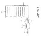
- FIG. 1is a schematic plan view of an alternating pressure mattress and blower
- FIG. 2is a schematic perspective view of the blower of the present invention
- FIG. 3is an exploded view of the alternating pressure rotor valve
- FIG. 4shows the gearmotor and rotor valve of the present invention
- FIG. 5is a side view of the gearmotor and printed circuit board of the present invention.
- FIG. 6Ais a schematic view of the rotor valve
- FIG. 6Bis a schematic view of the rotor valve allowing air to flow through both air inlets
- FIG. 6Cis a schmatic view of the rotor valve shutting off air from the second air inlet and allowing air to flow through the first air inlet;
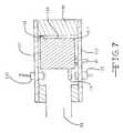
- FIG. 7is a cross-sectional view of an alternate valve assembly illustrating light sensors of the present invention.
- FIG. 8is a top view partially in cross-section of the valve assembly with the rotor valve shutting off air from the first air inlet and allowing air to flow through the second air inlet;
- FIG. 9is a top view partially in cross-section of the alternate valve assembly with the rotor valve allowing air to flow through both air inlets;
- FIG. 10Ais a perspective view of an alternate rotor valve
- FIG. 10Bis a top view of an alternate rotor valve
- FIG. 10Cis a side view of an alternate rotor valve
- FIG. 11is an exploded view of a further embodiment of an alternate rotor valve assembly of the present invention.
- the present inventionprovides an alternating pressure valve system for controlling the supply of fluid to an alternating pressure mattress.
- like reference numeralswill designate similar elements in the various embodiments of the present invention.
- FIG. 1an alternating pressure supply 11 of the present invention is illustrated.
- the alternating pressure supplyis connected to an alternating pressure mattress 13 via two hoses 17 and 19 .
- Hose 17supplies fluid to chambers or sacks 21 of the mattress and hose 19 supplies fluid to chambers or sacks 23 of the mattress.
- the fluid supplied to the mattressis air, which is compressible and helps to prevent high pressure points on a patient's skin.
- the mattressis preferably a low air loss mattress which deflates upon cessation of the supply of air to the mattress.
- the alternating pressure supplyis connected to a conventional AC power outlet via cord 15 .
- the alternating pressure supplyis better illustrated.
- the alternating pressure supplyis enclosed in a housing, not illustrated, that allows for air flow into the blower 51 and for the connection of the hoses to the air outlets 46 and 47 .
- the blowerreceives air from a circular air intake 53 .
- the front of the housingis a main control printed circuit board 25 with a LED bar graph 27 that indicates the relative pressure inside the mattress, a switch 29 to lower the pressure inside the mattress, a switch 31 to increase the pressure inside the mattress, a on/off/standby switch 33 , a switch 35 to turn on the alternating pressure and a switch 37 to turn on maximum inflation of the air cells.
- the pressure inside the mattressis controlled by the relative speed of the blower 51 .
- the preferred bloweris a Wind JammerTM 2 stage variable speed blower manufactured by AmetekTM, however other conventional blowers can also be used.
- a cable 39connects the main control board to a valve housing printed circuit board 41 .
- this boardreceives feedback from detectors in the housing as to the position of a rotor valve and controls the position of the rotor valve through controlling a gearmotor 43 .
- the gearmotoris an alternating 12 volt nominal DC motor, 800 I series manufactured by Craemer, however, other motors such as other DC motors by different manufacturers and stepped motors could be used.
- the gearmotor controlsmove a rotor valve within the valve housing. Attached to one end of the valve housing is the blower 51 . The other end of the valve housing has air outlets 47 that are threaded and receive hose connectors.
- the valve assembly 45comprises the valve housing, the circuit board, the gear motor, and a cover plate 65 (illustrated in FIG. 3 ).
- the valve housingis rectangular in shape with a first end with an air inlet 63 for receiving air from the blower's air output 83 , a second end for receiving hose connectors 64 , a solid top and bottom surface, and two side surfaces that form the rotor valve cylinder 61 .
- the housingis made out of a plastic material, preferably white DelrinTM, however other plastics, acrylics, metals, etc. could be used.
- the housingis machined with the following dimensions: height 2.35 inches, length 3.2 inches, depth 1.5 inches, air inlet diameter 1.25 inch, rotor valve cylinder radius 1.05 inches, air outlet radius 0.25 inches, however other dimensions could be used or the housing could be molded.
- a cover plate 65is attached to one side of the housing using screws 67 .
- the cover plateis made from steel, however other materials could be used.
- a gasketcan be placed between the air inlet of the housing and the air output of the blower to ensure a good seal.
- a rotor valve 69Inside the rotor valve cylinder is a rotor valve 69 .
- the rotor valveis a wedged shaped valve that has a top 73 sized to just fit inside the valve cylinder (currently a radius just slightly less than 1.05 inches).
- the remaining portion of the valve shaft 70is sized 0.020 less than the top (currently a radius of 1.03 inches).
- This differential in sizecreates a 0.020 gap between the outer edge of the wedge shaped valve and the inner wall of the valve cylinder. This gap allows for some air to flow past the valve and into an air outlet that the valve is covering up. In this way the flow of air is never entirely halted in any of the chambers of the air mattress when the controller is supplying alternating pressure to the mattress. If one wanted to completely block the air supply to the air chambers via the valve, then the valve body would have the same radius as the valve top.
- the bottom of the valveis a bottom circular plate 71 that just fits inside the valve cylinder.
- a spring cylindrical recess 74is provided that houses a spring 75 that keeps the valve from rubbing against the cover plate.
- a “D” shaped aperture 91At the bottom of the valve circular plate is a “D” shaped aperture 91 (see FIG. 4) that receives a “D” shaped drive shaft 81 of the gearmotor 43 .
- Two brass washers 77are provided between the bottom circular plate and the “D” shaped drive shaft.
- the valve housing printed circuit board 41is the cover plate for the valve housing side that contains the gear motor. On the surface of the circuit board that faces the interior of the valve housing are two infrared light detectors/emitters 79 .
- the detectors/emittersare located at two different radii from the drive shaft, currently one is placed at 0.95 inches and the other is placed at 0.75 inches.
- the detectors/emitters currently usedare part no. OR520 from OmronTM, however other standard detectors/emitters could be used.
- the circuit boardis attached to the housing via screws (not illustrated).
- FIG. 4illustrates the gearmotor, the rotor valve, and the positions of the infrared detectors/emitters.
- the rotor valveis preferably made out of a low reflective material such as black DelrinTM.
- Located on the bottom surface of the rotor valve bottomare a plurality of circular recesses 89 (currently four recesses). The recesses are placed at two different radii from the center of the valve bottom to correspond with the radii of detectors/emitters.
- the recessare filled with a white high-gloss paint that reflects infrared light.
- the feedback provided by the detectors/emitters to the circuit boardwill vary to indicate the correct valve position (see description for FIG. 6 below.)
- the circuit boardhas a signal buffer 95 ( 74 HC 04 ) and a 2-to-4 decoder 97 ( 74 HC 139 ) attached to its outer surface.
- the gear motoris attached to the circuit board via screws and mounting tabs 85 .
- a cable 39is attached to the circuit board via connectors 92 and 93 . The cable carries signals to and from the main control board.
- the gearmotoris a DC reversible motor. The motor will not run if there is no current provided to the leads 87 of the gearmotor or if the same current is provided to each lead.
- the gearmotorwill operate if current is provided to one lead and the other lead is grounded, and will reverse directions when the current and ground are reversed.
- FIGS. 6A-6Cillustrates the sensing provided by the two detectors/emitters.
- the wedge shaped valveWhen the wedge shaped valve is located ⁇ 60 degrees from the axis of the air intake 63 , the right air outlet 47 is covered by the valve restricting its air flow and thus reducing the corresponding pressure in the air chambers of the mattress connected to that outlet (see FIG. 6 A).
- the infrared light being emitted by the detectors/emitterswill then reflect off of the white paint within two recesses and both detectors/emitters will detect the light and transmit a signal to the circuit board.
- FIG. 6Bwhen the valve is centered along the air inlet axis, neither air outlet is covered, thus air can freely flow into both chambers of the mattress. This is the initial position of the valve such that the air mattress gets inflated quickly to support the patient. In this position, only one of the detectors/emitters detects infrared reflection, in the present invention the one that was set at the largest radius.
- APalternating pressure
- the AP switchwhen pressed, charges a 0.1 ⁇ F capacitor through a 10K resistor for debounce, then the signal is cleaned up with an HC- 14 inverter (U 9 ), and finally toggled by an HC 73 flip-flop (U 8 ).
- the Q-bar outputis “anded” in an HC 08 AND gate (U 10 ), with a signal from another HC 08 AND gate (U 12 ) that is high only when the blower is running, and MAX INFLATE is OFF.
- the resulting signal from the AND gateis named AP ENABLE, which means “OK to run the AP system”.
- AP operationis canceled when the system is in STANDBY or MAX INFLATE mode.
- AP functionwill resume, if previously activated, upon cancellation of MAX INFLATE.
- the two sensors on the AP circuit boardare positioned to face the back of the rotor, which has four reflective spots on it.
- the sensorseach emit an infrared light, and have transistors that conduct when the light is returned by the presence of a reflector.
- the sensorsare at two different radii, as are the reflective spots.
- the relationship between sensors and reflectorsare such that the three parking positions of the rotor conform to three of the four binary combinations.
- the de-coding of the binary sensor datais performed by a HC 139 on the AP unit's PCB.
- the output signalsare buffered by an HC 04 , on the same board.
- SenA “low”means the rotor is covering one of the ports, called port 1 .
- SenB lowmeans that the rotor is midway, or parked, between the ports. This is the non-AP position.
- SenC lowmeans the rotor is covering the other port, called port 2 .
- the trigger signalchanges state when the rotor moves over or away from one of the 60 degree limit sensors.
- Signals SenA and SenCare “ANDED” to derive Trig. When these signals are both high, this means that the rotor is not over either port.
- the use of a 74 HC 08 AND gateprovides a “low” output whenever the rotor moves so that it covers either port. This signal is inverted and delayed to allow data to settle at another I.C. This delayed signal is again inverted, so it also goes “low” when the turning rotor arrives over either port.
- Trigis used to initiate the timing sequence, which in effect disables the motor until the timer completes its cycle. Trig is also used to clock in the data that sets the motor terminal polarity.
- Position signal SenCgoes low, then the rotor moves from port I towards port 2 .
- Triggoes “low”, which starts the motor-disable timer (see below).
- This signalalso clocks in the new motor polarity data from signals SenA and SenC.
- the timercommands the motor to run again, it will be in the opposite direction.
- the timer signalis the output from the HC 221 , section B. This signal is combined into the motor drive signal (see below).
- the electric motoris disabled or enabled by this signal.
- This signalis a logical combination of APsel, SenB, and Timer. SenB and APsel are “ORED” together so that when AP is turned off (APsel goes low) the motor will turn the rotor until the center position sensor (SenB) goes low. These two low signals result in a low output, “ANDED” with the Timer signal, that shuts off power to the motor by disconnecting the ground connection.
- the AP circuitprovides for 4 seconds of movement of the rotor valve from one side to the other, and then three minutes of no rotor valve movement until the rotor valve reverses to the other side.
- the three minute timingis currently preferred, however other timing from 0 seconds (constantly reversing pressure) to about five minutes of no valve movement is recommended for use depending on the patient's needs and condition. As would be recognized by a person skilled in the art, other timing sequences could also be used.
- FIGS. 7-10Can alternate embodiment is illustrated.
- the housing 49is identical to the housing of the first embodiment.
- the rotor valve 117is wedged shaped as illustrated in FIGS. 10A-10B with the apex 121 of the wedge extending beyond the center of the wedge's radius pivot point 122 .
- the wedge valvehas a protruding top 119 similar to the wedge valve of the first embodiment and a slightly recessed shaft 120 to allow some air flow past the covered air outlet.
- Provided on the cover plate 111are three light emitters 125 placed along a radius in holes 127 (see FIGS. 8 and 9 ). The light emitters are currently red LEDs, however other light emitters could be used.
- the control circuitwould now receive the signals from the detectors and depending on which detector is blocked by the apex of the wedge, a unique signal is generated allows for the control and timing of the rotor valve position (similar to the valve positions illustrated in FIGS. 6 A- 6 C).
- FIG. 11a further embodiment is illustrated as a schematic exploded view.
- a blower 51 with air outlet 83is attached to a rotor valve housing 49 .
- a gasket 131is used between the blower and the housing to ensure a tight seal.
- the rotor valve 69is controlled by an electric motor 43 which is attached to a side plate 41 .
- the side plateis provided with a plurality of holes 133 which screws 67 pass through.
- the housingis provided with a plurality of threaded screw holes 135 for the screws 67 to anchor into.
- the electric motoris controlled by the use of leads 140 and 142 , whereby switching the polarity of the leads will reverse the motor.
- FIG. 1On the opposite side of the housing from the electric motor is another side plate 65 with holes 133 for attaching to the housing using screws 67 .
- Two threaded air outlets 47are provided for in the housing opposite the air inlet 63 .
- Two connectors 64are threaded into the air outlets for connecting to the two sets of air sack within the air mattress.
- On the top and bottom of the housingis provided two threaded tap holes 137 where two connectors 139 are threaded into the tap holes.
- Two pressure hoses 141are then connected to the connectors 139 .
- Each pressure hoseis attached to a pressure sensor 143 for sensing the relative pressure in each line.
- the pressure sensorsare attached by leads 145 to a control box (not illustrated) similar to the box 11 of FIG.
- the air outletsare connected to hoses 17 and 19 (see FIG. 1) which are then respectively connected to air sacks 21 and 23 .
- the air sacksare preferably low air loss air sacks that allow for air to flow out of small holes on the air mattress which helps the patients skin from becoming moist and prone to ulceration.
- the pressure sensorscould be placed anywhere along the air outlet pathway and could be placed within the air sacks themselves.
- the pressure sensorscould be placed directly within the tap holes 137 .
- FIG. 11operates by first having the rotor valve 69 position half way between the air outlets 47 such that air from the blower 51 can rapidly inflate the two sets of air sacks. Once the air sacks are inflated to a certain pressure, typically in the range of 8 to 24 mm Hg, as detected by pressure sensors 143 , the alternating pressure function of the invention can begin. A switch on the control box allows for the alternating pressure function. The rotor valve will then rotate to occlude one of the outlets. In the preferred embodiment, the rotor valve is sized such that most of the air will be deflected to one of the outlets, but some of the air will be allowed to flow around the rotor valve and allow air to flow into the occluded outlet.
- the air sacks that are occludedwill have about 50-60% of the pressure in the air sacs not occluded.
- air sacks 21may have a pressure of about 32 mm Hg
- air sacks 23may have a pressure of about 17 mm Hg. The amount of pressure in the air sacks is monitored and can be adjusted depending on the needs of the patient and the comfort of the patient.
- the pressure in the air sacks that are not occludedis controlled to about 20 mm Hg to about 35 mm Hg.
- the length of time one set of air sacks is occludedis also adjustable ranging from constant alternating pressure to five minutes of pressure in one set before the rotor valve rotates to occlude the other air outlet. If it is desirable to completely eliminate all pressure from one set of the air sacks, then the rotor valve can be sized such that no air is allowed to flow around it while occluding one set of air sacks.
Landscapes
- Engineering & Computer Science (AREA)
- General Engineering & Computer Science (AREA)
- Mechanical Engineering (AREA)
- Invalid Beds And Related Equipment (AREA)
- Mattresses And Other Support Structures For Chairs And Beds (AREA)
Abstract
Description
Claims (17)
Priority Applications (2)
| Application Number | Priority Date | Filing Date | Title |
|---|---|---|---|
| US09/626,434US6745996B1 (en) | 1997-07-28 | 2000-07-27 | Alternating pressure valve system |
| US10/690,197US20040256588A1 (en) | 1997-07-28 | 2003-10-21 | Alternating pressure valve system |
Applications Claiming Priority (3)
| Application Number | Priority Date | Filing Date | Title |
|---|---|---|---|
| US5399997P | 1997-07-28 | 1997-07-28 | |
| US12362198A | 1998-07-28 | 1998-07-28 | |
| US09/626,434US6745996B1 (en) | 1997-07-28 | 2000-07-27 | Alternating pressure valve system |
Related Parent Applications (1)
| Application Number | Title | Priority Date | Filing Date |
|---|---|---|---|
| US12362198AContinuation-In-Part | 1997-07-28 | 1998-07-28 |
Related Child Applications (1)
| Application Number | Title | Priority Date | Filing Date |
|---|---|---|---|
| US10/690,197ContinuationUS20040256588A1 (en) | 1997-07-28 | 2003-10-21 | Alternating pressure valve system |
Publications (1)
| Publication Number | Publication Date |
|---|---|
| US6745996B1true US6745996B1 (en) | 2004-06-08 |
Family
ID=32328522
Family Applications (2)
| Application Number | Title | Priority Date | Filing Date |
|---|---|---|---|
| US09/626,434Expired - LifetimeUS6745996B1 (en) | 1997-07-28 | 2000-07-27 | Alternating pressure valve system |
| US10/690,197AbandonedUS20040256588A1 (en) | 1997-07-28 | 2003-10-21 | Alternating pressure valve system |
Family Applications After (1)
| Application Number | Title | Priority Date | Filing Date |
|---|---|---|---|
| US10/690,197AbandonedUS20040256588A1 (en) | 1997-07-28 | 2003-10-21 | Alternating pressure valve system |
Country Status (1)
| Country | Link |
|---|---|
| US (2) | US6745996B1 (en) |
Cited By (28)
| Publication number | Priority date | Publication date | Assignee | Title |
|---|---|---|---|---|
| US20050204828A1 (en)* | 2004-03-18 | 2005-09-22 | Metertek Technology Inc. | Flow meter |
| US20070056114A1 (en)* | 2005-09-09 | 2007-03-15 | Corey Lewison | Multi-zone coil construction airbed |
| US20070113352A1 (en)* | 2005-08-10 | 2007-05-24 | Craig Poulos | Therapeutic mattress |
| US20070266499A1 (en)* | 2006-05-09 | 2007-11-22 | Hill-Rom Services, Inc. | Pulmonary mattress |
| US20070272219A1 (en)* | 2003-12-15 | 2007-11-29 | Inergy Auto. Systems Research (Societe Anonyme) | Electronically Controlled Electromechanical Valve |
| US20080098529A1 (en)* | 2006-10-26 | 2008-05-01 | Thierry Flocard | Device and method for controlling humidity at the surface of a supporting item of the mattress type |
| US20080307582A1 (en)* | 2007-06-18 | 2008-12-18 | Thierry Flocard | Support Device of the Mattress Type Comprising A Heterogeneous Inflatable Structure |
| US20090100604A1 (en)* | 2007-10-18 | 2009-04-23 | Jean-Luc Caminade | Method of inflating, in alternating manner, a support device having inflatable cells, and a device for implementing the method |
| US20100071713A1 (en)* | 2008-09-23 | 2010-03-25 | Larada Sciences Inc. | Airflow applicators and related treatment methods |
| US20100308241A1 (en)* | 2006-03-03 | 2010-12-09 | Kevin Doyle | Electronically controlled valve actuator in a pool or spa water line system |
| US7849545B2 (en) | 2006-11-14 | 2010-12-14 | Hill-Rom Industries Sa | Control system for hospital bed mattress |
| US8108957B2 (en) | 2007-05-31 | 2012-02-07 | Hill-Rom Services, Inc. | Pulmonary mattress |
| US20130008543A1 (en)* | 2011-07-08 | 2013-01-10 | Basf Se | Pipe switch with metering function |
| US20140259432A1 (en)* | 2013-03-14 | 2014-09-18 | Kap Medical, Inc. | Patient support apparatus and method |
| US9049943B2 (en) | 2007-10-18 | 2015-06-09 | Hill-Rom Industries Sa | Mattress structure including low air loss |
| DE102014106629A1 (en) | 2014-05-12 | 2015-11-12 | Dr. Ing. H.C. F. Porsche Aktiengesellschaft | Valve |
| US9329076B2 (en) | 2012-06-21 | 2016-05-03 | Hill-Rom Services, Inc. | Patient support systems and methods of use |
| WO2017187145A1 (en)* | 2016-04-25 | 2017-11-02 | Direct Healthcare Services Limited | Mattress system and connector |
| US9833369B2 (en) | 2012-06-21 | 2017-12-05 | Hill-Rom Services, Inc. | Patient support systems and methods of use |
| US20180289174A1 (en)* | 2017-04-10 | 2018-10-11 | Hill-Rom Services, Inc. | Mattress overlay for p&v, turn assist and mcm |
| US10844967B2 (en)* | 2018-05-18 | 2020-11-24 | Guangdong Travelmall Health Technology Co., Ltd. | Inflation system |
| US11058227B2 (en) | 2015-04-23 | 2021-07-13 | Sealy Technology, Llc | Systems and methods for adjusting the firmness and profile of a mattress assembly |
| US11207945B2 (en)* | 2016-12-01 | 2021-12-28 | Zhejiang Sanhua Intelligent Controls Co., Ltd. | Flow control device, and control system and control method therefor |
| EP4112031A1 (en)* | 2021-06-30 | 2023-01-04 | Hill-Rom Services, Inc. | Manifold assembly for pneumatic system |
| GB2609597A (en)* | 2021-06-11 | 2023-02-15 | Cloud Cair Ltd | A pressure relief mattress |
| US12102577B2 (en) | 2012-06-21 | 2024-10-01 | Hill-Rom Services, Inc. | Mattress bladder control using a bleed valve |
| US12150908B2 (en) | 2014-04-18 | 2024-11-26 | Kreg Medical, Inc. | Patient support with stand-up and sit features |
| US12208041B2 (en) | 2008-06-27 | 2025-01-28 | Kreg Medical, Inc. | Bed with frame assembly |
Citations (13)
| Publication number | Priority date | Publication date | Assignee | Title |
|---|---|---|---|---|
| US3373771A (en)* | 1965-04-29 | 1968-03-19 | Besler Corp | Gas flow modulator valve |
| US3545470A (en)* | 1967-07-24 | 1970-12-08 | Hamilton Neil King Paton | Differential-pressure flow-controlling valve mechanism |
| US4197837A (en)* | 1977-10-04 | 1980-04-15 | American Hospital Supply Corporation | Inflatable-deflatable pad and air control system therefor |
| US4935968A (en)* | 1985-05-10 | 1990-06-26 | Mediscus Products, Ltd. | Patient support appliances |
| US4944060A (en)* | 1989-03-03 | 1990-07-31 | Peery John R | Mattress assembly for the prevention and treatment of decubitus ulcers |
| US5035016A (en)* | 1987-11-10 | 1991-07-30 | Nikko Co., Ltd. | Air-mat apparatus |
| US5183077A (en)* | 1991-12-09 | 1993-02-02 | Raymond Keiper | Flow control valve |
| US5235713A (en)* | 1990-11-06 | 1993-08-17 | Bio Clinic Corporation | Fluid filled flotation mattress |
| US5320141A (en)* | 1991-12-09 | 1994-06-14 | Raymond Keiper | Flow control valve |
| US5502380A (en)* | 1994-04-28 | 1996-03-26 | Rosemount Inc. | Analog weighted binary absolute position encoder including an array of sense resistors each having material responsive to FWX and nonresponsive to flux |
| US5529026A (en)* | 1993-07-23 | 1996-06-25 | Firma Carl Freudenberg | Regulating Valve |
| US5685036A (en)* | 1996-02-15 | 1997-11-11 | Geomarine Systems, Inc. | Alternating pressure mattress system and method |
| US5967185A (en)* | 1996-12-12 | 1999-10-19 | Behr Gmbh & Co. | Rotary valve |
Family Cites Families (5)
| Publication number | Priority date | Publication date | Assignee | Title |
|---|---|---|---|---|
| US1750927A (en)* | 1928-02-16 | 1930-03-18 | American Brass & Fire Equipmen | Fire-hose connecter head |
| GB1074836A (en)* | 1963-08-19 | 1967-07-05 | Koltek Oy | Fluid control valve |
| FI60766C (en)* | 1975-08-14 | 1982-03-10 | Lehtinen Kari | VALVE FOERSEDD MED ETT VRIDBART AVSTAENGNINGSORGAN |
| DE2705626A1 (en)* | 1977-02-10 | 1978-08-24 | Waldner Gmbh & Co Hermann | SHUT-OFF VALVE |
| US4470429A (en)* | 1982-05-06 | 1984-09-11 | Jandy Industries, Inc. | Three-way valve |
- 2000
- 2000-07-27USUS09/626,434patent/US6745996B1/ennot_activeExpired - Lifetime
- 2003
- 2003-10-21USUS10/690,197patent/US20040256588A1/ennot_activeAbandoned
Patent Citations (13)
| Publication number | Priority date | Publication date | Assignee | Title |
|---|---|---|---|---|
| US3373771A (en)* | 1965-04-29 | 1968-03-19 | Besler Corp | Gas flow modulator valve |
| US3545470A (en)* | 1967-07-24 | 1970-12-08 | Hamilton Neil King Paton | Differential-pressure flow-controlling valve mechanism |
| US4197837A (en)* | 1977-10-04 | 1980-04-15 | American Hospital Supply Corporation | Inflatable-deflatable pad and air control system therefor |
| US4935968A (en)* | 1985-05-10 | 1990-06-26 | Mediscus Products, Ltd. | Patient support appliances |
| US5035016A (en)* | 1987-11-10 | 1991-07-30 | Nikko Co., Ltd. | Air-mat apparatus |
| US4944060A (en)* | 1989-03-03 | 1990-07-31 | Peery John R | Mattress assembly for the prevention and treatment of decubitus ulcers |
| US5235713A (en)* | 1990-11-06 | 1993-08-17 | Bio Clinic Corporation | Fluid filled flotation mattress |
| US5183077A (en)* | 1991-12-09 | 1993-02-02 | Raymond Keiper | Flow control valve |
| US5320141A (en)* | 1991-12-09 | 1994-06-14 | Raymond Keiper | Flow control valve |
| US5529026A (en)* | 1993-07-23 | 1996-06-25 | Firma Carl Freudenberg | Regulating Valve |
| US5502380A (en)* | 1994-04-28 | 1996-03-26 | Rosemount Inc. | Analog weighted binary absolute position encoder including an array of sense resistors each having material responsive to FWX and nonresponsive to flux |
| US5685036A (en)* | 1996-02-15 | 1997-11-11 | Geomarine Systems, Inc. | Alternating pressure mattress system and method |
| US5967185A (en)* | 1996-12-12 | 1999-10-19 | Behr Gmbh & Co. | Rotary valve |
Cited By (58)
| Publication number | Priority date | Publication date | Assignee | Title |
|---|---|---|---|---|
| US20070272219A1 (en)* | 2003-12-15 | 2007-11-29 | Inergy Auto. Systems Research (Societe Anonyme) | Electronically Controlled Electromechanical Valve |
| US7444997B2 (en)* | 2003-12-15 | 2008-11-04 | Inergy Automotive Systems Research (Societe Anonyme) | Electronically controlled electromechanical valve |
| US20050204828A1 (en)* | 2004-03-18 | 2005-09-22 | Metertek Technology Inc. | Flow meter |
| US7197943B2 (en)* | 2004-03-18 | 2007-04-03 | Metertek Technology Inc. | Flow meter with cover plate having rubber filling plate with recessions |
| US7509698B2 (en) | 2005-08-10 | 2009-03-31 | Kreg Medical, Inc. | Therapeutic mattress |
| US20100000020A1 (en)* | 2005-08-10 | 2010-01-07 | Craig Poulos | Dynamic therapy bed system |
| US7716766B2 (en) | 2005-08-10 | 2010-05-18 | Kreg Medical, Inc. | Therapeutic mattress |
| US20080115288A1 (en)* | 2005-08-10 | 2008-05-22 | Craig Poulos | Therapeutic mattress |
| US20070113352A1 (en)* | 2005-08-10 | 2007-05-24 | Craig Poulos | Therapeutic mattress |
| US20090183313A1 (en)* | 2005-08-10 | 2009-07-23 | Craig Poulos | Therapeutic mattress |
| US20110163885A1 (en)* | 2005-08-10 | 2011-07-07 | Craig Poulos | Adjustable therapeutic mattress |
| US7536739B2 (en) | 2005-08-10 | 2009-05-26 | Kreg Medical, Inc. | Therapeutic mattress |
| US20070056114A1 (en)* | 2005-09-09 | 2007-03-15 | Corey Lewison | Multi-zone coil construction airbed |
| US20100308241A1 (en)* | 2006-03-03 | 2010-12-09 | Kevin Doyle | Electronically controlled valve actuator in a pool or spa water line system |
| US8474074B2 (en) | 2006-05-09 | 2013-07-02 | Hill-Rom Services, Inc. | Pulmonary mattress |
| US20070266499A1 (en)* | 2006-05-09 | 2007-11-22 | Hill-Rom Services, Inc. | Pulmonary mattress |
| US7975335B2 (en) | 2006-05-09 | 2011-07-12 | Hill-Rom Services, Inc. | Pulmonary mattress |
| US20080098529A1 (en)* | 2006-10-26 | 2008-05-01 | Thierry Flocard | Device and method for controlling humidity at the surface of a supporting item of the mattress type |
| US7975331B2 (en) | 2006-10-26 | 2011-07-12 | Hill-Rom Industries Sa | Device and method for controlling humidity at the surface of a supporting item of the mattress type |
| US7849545B2 (en) | 2006-11-14 | 2010-12-14 | Hill-Rom Industries Sa | Control system for hospital bed mattress |
| US8584279B2 (en) | 2007-05-31 | 2013-11-19 | Hill-Rom Services, Inc. | Pulmonary mattress |
| US8108957B2 (en) | 2007-05-31 | 2012-02-07 | Hill-Rom Services, Inc. | Pulmonary mattress |
| US20080307582A1 (en)* | 2007-06-18 | 2008-12-18 | Thierry Flocard | Support Device of the Mattress Type Comprising A Heterogeneous Inflatable Structure |
| US7849544B2 (en) | 2007-06-18 | 2010-12-14 | Hill-Rom Industries Sa | Support device of the mattress type comprising a heterogeneous inflatable structure |
| US8104126B2 (en) | 2007-10-18 | 2012-01-31 | Hill-Rom Industries Sa | Method of inflating, in alternating manner, a support device having inflatable cells, and a device for implementing the method |
| US20090100604A1 (en)* | 2007-10-18 | 2009-04-23 | Jean-Luc Caminade | Method of inflating, in alternating manner, a support device having inflatable cells, and a device for implementing the method |
| US9049943B2 (en) | 2007-10-18 | 2015-06-09 | Hill-Rom Industries Sa | Mattress structure including low air loss |
| US12208041B2 (en) | 2008-06-27 | 2025-01-28 | Kreg Medical, Inc. | Bed with frame assembly |
| US20100071713A1 (en)* | 2008-09-23 | 2010-03-25 | Larada Sciences Inc. | Airflow applicators and related treatment methods |
| US8475510B2 (en) | 2008-09-23 | 2013-07-02 | Larada Sciences, Inc. | Airflow applicators and related treatment methods |
| US9464722B2 (en)* | 2011-07-08 | 2016-10-11 | Basf Se | Pipe switch with metering function |
| US20130008543A1 (en)* | 2011-07-08 | 2013-01-10 | Basf Se | Pipe switch with metering function |
| US10391008B2 (en) | 2012-06-21 | 2019-08-27 | Hill-Rom Services, Inc. | Patient support system and methods of use |
| US11116681B2 (en) | 2012-06-21 | 2021-09-14 | Hill-Rom Services, Inc. | Patient support systems and methods of use |
| US9655457B2 (en) | 2012-06-21 | 2017-05-23 | Hill-Rom Services, Inc. | Patient support systems and methods of use |
| US9833369B2 (en) | 2012-06-21 | 2017-12-05 | Hill-Rom Services, Inc. | Patient support systems and methods of use |
| US9329076B2 (en) | 2012-06-21 | 2016-05-03 | Hill-Rom Services, Inc. | Patient support systems and methods of use |
| US10555850B2 (en) | 2012-06-21 | 2020-02-11 | Hill-Rom Services, Inc. | Patient support systems and methods of use |
| US10806655B2 (en) | 2012-06-21 | 2020-10-20 | Hill-Rom Services, Inc. | Mattress bladder control during patient bed egress |
| US12102577B2 (en) | 2012-06-21 | 2024-10-01 | Hill-Rom Services, Inc. | Mattress bladder control using a bleed valve |
| US9801767B2 (en)* | 2013-03-14 | 2017-10-31 | Kap Medical, Inc. | Patient support apparatus and method |
| US20140259432A1 (en)* | 2013-03-14 | 2014-09-18 | Kap Medical, Inc. | Patient support apparatus and method |
| US12239593B2 (en) | 2014-04-18 | 2025-03-04 | Kreg Medical, Inc. | Patient support with stand-up and sit features |
| US12239594B2 (en) | 2014-04-18 | 2025-03-04 | Kreg Medical, Inc. | Patient support with stand-up and sit features |
| US12150908B2 (en) | 2014-04-18 | 2024-11-26 | Kreg Medical, Inc. | Patient support with stand-up and sit features |
| DE102014106629A1 (en) | 2014-05-12 | 2015-11-12 | Dr. Ing. H.C. F. Porsche Aktiengesellschaft | Valve |
| US11910929B2 (en) | 2015-04-23 | 2024-02-27 | Sealy Technology, Llc | Systems and methods for adjusting the firmness and profile of a mattress assembly |
| US11058227B2 (en) | 2015-04-23 | 2021-07-13 | Sealy Technology, Llc | Systems and methods for adjusting the firmness and profile of a mattress assembly |
| WO2017187145A1 (en)* | 2016-04-25 | 2017-11-02 | Direct Healthcare Services Limited | Mattress system and connector |
| US11207945B2 (en)* | 2016-12-01 | 2021-12-28 | Zhejiang Sanhua Intelligent Controls Co., Ltd. | Flow control device, and control system and control method therefor |
| US11684169B2 (en) | 2017-04-10 | 2023-06-27 | Hill-Rom Services, Inc. | Rotary plate valve having seal anti-herniation structure |
| US10856668B2 (en)* | 2017-04-10 | 2020-12-08 | Hill-Rom Services, Inc. | Mattress overlay control system with rotary valves and graphical user interface for percussion and vibration, turn assist and microclimate management |
| US20180289174A1 (en)* | 2017-04-10 | 2018-10-11 | Hill-Rom Services, Inc. | Mattress overlay for p&v, turn assist and mcm |
| US10844967B2 (en)* | 2018-05-18 | 2020-11-24 | Guangdong Travelmall Health Technology Co., Ltd. | Inflation system |
| GB2609597A (en)* | 2021-06-11 | 2023-02-15 | Cloud Cair Ltd | A pressure relief mattress |
| EP4112031A1 (en)* | 2021-06-30 | 2023-01-04 | Hill-Rom Services, Inc. | Manifold assembly for pneumatic system |
| US20230000703A1 (en)* | 2021-06-30 | 2023-01-05 | Hill-Rom Services, Inc. | Manifold assembly for pneumatic system |
| US12290484B2 (en)* | 2021-06-30 | 2025-05-06 | Hill-Rom Services, Inc. | Manifold assembly for pneumatic system |
Also Published As
| Publication number | Publication date |
|---|---|
| US20040256588A1 (en) | 2004-12-23 |
Similar Documents
| Publication | Publication Date | Title |
|---|---|---|
| US6745996B1 (en) | Alternating pressure valve system | |
| US6698046B1 (en) | Air mattress control unit | |
| US5542146A (en) | Electronic vacuum cleaner control system | |
| US5904172A (en) | Valve enclosure assembly | |
| CA1292655C (en) | Check valve for a parenteral solution delivery system | |
| US4784577A (en) | Pump pressure sensor | |
| US5647852A (en) | Lavage system including a cassette assembly | |
| DE69731464D1 (en) | AMBULANTE, MICROPROCESSOR CONTROLLED VOLUMETRIC DISPOSABLE PUMP | |
| CA2596504A1 (en) | Inflatable device with recessed fluid controller and modified adjustment device | |
| BR102014027088A2 (en) | valve-maintained air-maintained tire and method | |
| CA2351342A1 (en) | Rotary valve | |
| CA2199161A1 (en) | System for determining motor position in a biomedical device | |
| AU733498B2 (en) | Pressure control system | |
| US6955527B2 (en) | Two-way mounting air pump with an inflation mode and a deflation mode | |
| CA2409588A1 (en) | Food processor with reversible motor feature | |
| WO2014143784A2 (en) | Bidirectional fluid flow valve and method | |
| US20020198478A1 (en) | Massaging device for eliminating fat | |
| US20220218564A1 (en) | Smart water fill system for spa | |
| KR100330076B1 (en) | automatic valve | |
| KR200344613Y1 (en) | Sensor for sensing the human body's unmoving moment | |
| KR102514225B1 (en) | Massage device | |
| JP3515433B2 (en) | How to set the non-exhaust position of the rotary valve | |
| JPH0810308Y2 (en) | Air supply and discharge control device for air mat | |
| CN1177080A (en) | Safety device and control method for a gas device | |
| JPH0880329A (en) | Massage machine |
Legal Events
| Date | Code | Title | Description |
|---|---|---|---|
| AS | Assignment | Owner name:GAYMAR INDUSTRIES, INC., NEW YORK Free format text:ASSIGNMENT OF ASSIGNORS INTEREST;ASSIGNOR:GUTHRIE, BRIAN;REEL/FRAME:014312/0215 Effective date:20030717 | |
| STCF | Information on status: patent grant | Free format text:PATENTED CASE | |
| FPAY | Fee payment | Year of fee payment:4 | |
| AS | Assignment | Owner name:GENERAL ELECTRIC CAPITAL CORPORATION, AS COLLATERA Free format text:SECURITY AGREEMENT;ASSIGNOR:GAYMAR INDUSTRIES, INC.;REEL/FRAME:022473/0556 Effective date:20090330 | |
| AS | Assignment | Owner name:GAYMAR INDUSTRIES, INC., NEW YORK Free format text:RELEASE BY SECURED PARTY;ASSIGNOR:GENERAL ELECTRIC CAPITAL CORPORATION;REEL/FRAME:025114/0294 Effective date:20101001 | |
| FEPP | Fee payment procedure | Free format text:PAT HOLDER NO LONGER CLAIMS SMALL ENTITY STATUS, ENTITY STATUS SET TO UNDISCOUNTED (ORIGINAL EVENT CODE: STOL); ENTITY STATUS OF PATENT OWNER: LARGE ENTITY | |
| FPAY | Fee payment | Year of fee payment:8 | |
| AS | Assignment | Owner name:STRYKER CORPORATION, MICHIGAN Free format text:ASSIGNMENT OF ASSIGNORS INTEREST;ASSIGNOR:GAYMAR INDUSTRIES, INC.;REEL/FRAME:027025/0001 Effective date:20110819 | |
| FEPP | Fee payment procedure | Free format text:PAYOR NUMBER ASSIGNED (ORIGINAL EVENT CODE: ASPN); ENTITY STATUS OF PATENT OWNER: LARGE ENTITY | |
| FPAY | Fee payment | Year of fee payment:12 |