US6745592B1 - Apparatus and method for dispensing a frozen alcoholic beverage - Google Patents
Apparatus and method for dispensing a frozen alcoholic beverageDownload PDFInfo
- Publication number
- US6745592B1 US6745592B1US10/295,722US29572202AUS6745592B1US 6745592 B1US6745592 B1US 6745592B1US 29572202 AUS29572202 AUS 29572202AUS 6745592 B1US6745592 B1US 6745592B1
- Authority
- US
- United States
- Prior art keywords
- beverage
- freezing
- dispensing
- component
- product
- Prior art date
- Legal status (The legal status is an assumption and is not a legal conclusion. Google has not performed a legal analysis and makes no representation as to the accuracy of the status listed.)
- Expired - Fee Related
Links
- 235000013334alcoholic beverageNutrition0.000titleclaimsabstractdescription45
- 238000000034methodMethods0.000titleabstractdescription11
- 235000013361beverageNutrition0.000claimsabstractdescription144
- 230000008014freezingEffects0.000claimsabstractdescription76
- 238000007710freezingMethods0.000claimsabstractdescription76
- 239000007788liquidSubstances0.000claimsabstractdescription28
- LFQSCWFLJHTTHZ-UHFFFAOYSA-NEthanolChemical compoundCCOLFQSCWFLJHTTHZ-UHFFFAOYSA-N0.000claimsdescription49
- 239000000203mixtureSubstances0.000claimsdescription12
- 238000005070samplingMethods0.000claimsdescription12
- 238000004891communicationMethods0.000claimsdescription8
- 230000008859changeEffects0.000claimsdescription4
- 230000007246mechanismEffects0.000claims14
- 230000004075alterationEffects0.000claims2
- 230000000903blocking effectEffects0.000claims2
- XLYOFNOQVPJJNP-UHFFFAOYSA-NwaterSubstancesOXLYOFNOQVPJJNP-UHFFFAOYSA-N0.000description27
- CURLTUGMZLYLDI-UHFFFAOYSA-NCarbon dioxideChemical compoundO=C=OCURLTUGMZLYLDI-UHFFFAOYSA-N0.000description24
- 239000004615ingredientSubstances0.000description14
- 239000006188syrupSubstances0.000description14
- 235000020357syrupNutrition0.000description14
- 229910002092carbon dioxideInorganic materials0.000description12
- 239000001569carbon dioxideSubstances0.000description12
- 238000010586diagramMethods0.000description6
- 235000013405beerNutrition0.000description5
- 239000000796flavoring agentSubstances0.000description5
- 235000019634flavorsNutrition0.000description5
- 238000005192partitionMethods0.000description4
- 238000012546transferMethods0.000description4
- 230000004913activationEffects0.000description3
- 238000001994activationMethods0.000description3
- 230000001476alcoholic effectEffects0.000description3
- 230000009471actionEffects0.000description2
- 235000014171carbonated beverageNutrition0.000description2
- 230000005484gravityEffects0.000description2
- 238000007373indentationMethods0.000description2
- 229920001684low density polyethylenePolymers0.000description2
- 239000004702low-density polyethyleneSubstances0.000description2
- 238000005259measurementMethods0.000description2
- 230000004048modificationEffects0.000description2
- 238000012986modificationMethods0.000description2
- 235000019629palatabilityNutrition0.000description2
- 230000008569processEffects0.000description2
- 230000011664signalingEffects0.000description2
- BVKZGUZCCUSVTD-UHFFFAOYSA-LCarbonateChemical compound[O-]C([O-])=OBVKZGUZCCUSVTD-UHFFFAOYSA-L0.000description1
- 230000003213activating effectEffects0.000description1
- 230000002411adverseEffects0.000description1
- 230000002939deleterious effectEffects0.000description1
- 238000011038discontinuous diafiltration by volume reductionMethods0.000description1
- 238000009413insulationMethods0.000description1
- 238000012423maintenanceMethods0.000description1
- 230000002265preventionEffects0.000description1
- 238000012545processingMethods0.000description1
- 230000000087stabilizing effectEffects0.000description1
- 235000013529tequilaNutrition0.000description1
- 238000013024troubleshootingMethods0.000description1
- 230000000007visual effectEffects0.000description1
- 235000013522vodkaNutrition0.000description1
- 235000015041whiskyNutrition0.000description1
Images


Classifications
- A—HUMAN NECESSITIES
- A23—FOODS OR FOODSTUFFS; TREATMENT THEREOF, NOT COVERED BY OTHER CLASSES
- A23G—COCOA; COCOA PRODUCTS, e.g. CHOCOLATE; SUBSTITUTES FOR COCOA OR COCOA PRODUCTS; CONFECTIONERY; CHEWING GUM; ICE-CREAM; PREPARATION THEREOF
- A23G9/00—Frozen sweets, e.g. ice confectionery, ice-cream; Mixtures therefor
- A23G9/04—Production of frozen sweets, e.g. ice-cream
- A23G9/045—Production of frozen sweets, e.g. ice-cream of slush-ice, e.g. semi-frozen beverage
- A—HUMAN NECESSITIES
- A23—FOODS OR FOODSTUFFS; TREATMENT THEREOF, NOT COVERED BY OTHER CLASSES
- A23G—COCOA; COCOA PRODUCTS, e.g. CHOCOLATE; SUBSTITUTES FOR COCOA OR COCOA PRODUCTS; CONFECTIONERY; CHEWING GUM; ICE-CREAM; PREPARATION THEREOF
- A23G9/00—Frozen sweets, e.g. ice confectionery, ice-cream; Mixtures therefor
- A23G9/04—Production of frozen sweets, e.g. ice-cream
- A23G9/22—Details, component parts or accessories of apparatus insofar as not peculiar to a single one of the preceding groups
- A23G9/28—Details, component parts or accessories of apparatus insofar as not peculiar to a single one of the preceding groups for portioning or dispensing
- A23G9/281—Details, component parts or accessories of apparatus insofar as not peculiar to a single one of the preceding groups for portioning or dispensing at the discharge end of freezing chambers
- B—PERFORMING OPERATIONS; TRANSPORTING
- B67—OPENING, CLOSING OR CLEANING BOTTLES, JARS OR SIMILAR CONTAINERS; LIQUID HANDLING
- B67D—DISPENSING, DELIVERING OR TRANSFERRING LIQUIDS, NOT OTHERWISE PROVIDED FOR
- B67D1/00—Apparatus or devices for dispensing beverages on draught
- B67D1/02—Beer engines or like manually-operable pumping apparatus
- B—PERFORMING OPERATIONS; TRANSPORTING
- B67—OPENING, CLOSING OR CLEANING BOTTLES, JARS OR SIMILAR CONTAINERS; LIQUID HANDLING
- B67D—DISPENSING, DELIVERING OR TRANSFERRING LIQUIDS, NOT OTHERWISE PROVIDED FOR
- B67D1/00—Apparatus or devices for dispensing beverages on draught
- B67D1/08—Details
- B67D1/0857—Cooling arrangements
Definitions
- the present inventionrelates to an apparatus and method for dispensing a frozen alcoholic beverage, and, more particularly, to an apparatus and method in which an alcoholic beverage component is mixed with another flavored liquid component and water prior to freezing and dispensing as a single beverage product.
- Frozen beverage dispensersare common in the prior art, with the primary function of such dispensers being to mix water and a flavored component, freeze the mixture, and then dispense the frozen beverage product with a slush-like consistency.
- a typical frozen carbonated beverage machinecommonly referred to as an “FCB” machine”
- FCBfrozen carbonated beverage machine
- wateris first carbonated with carbon dioxide.
- the carbonated wateris mixed with a syrup to form a carbonated beverage mixture, and then the mixture is frozen for subsequent dispensing.
- the present inventionis an apparatus and method for dispensing a frozen alcoholic beverage in which an alcoholic beverage component is mixed with at least one other liquid component prior to freezing and dispensing as a frozen beverage product.
- a preferred dispensing apparatusis comprised of two major components: a base cart, which contains all of the components needed to pump and mix the beverage components prior to freezing to form a single beverage product; and a freezing and dispensing system.
- An ingredient cabinet in the front portion of the base cartstores separate containers of the different beverage components, each of which is in liquid communication with a respective component feed system.
- component feed systemsare located on a mixing panel in a rear portion of the base cart, each such component feed system including tubing and various valves for controlling the flow of each beverage component.
- the componentsare introduced into and mixed in a common conduit or a mixing area.
- the mixed beveragethen exits the base cart and is introduced into the freezing and dispensing system.
- the preferred freezing and dispensing systemcontains all of the components needed to freeze and dispense a frozen alcoholic beverage with a desired consistency.
- the systemincludes a standard freezer that is commonly used in frozen beverage dispensers, including a freezing and dispensing barrel.
- the freezing and dispensing systemalso includes an accumulator which receives mixed beverage from the mixing area.
- the accumulatoralso has an outlet in liquid communication with the freezing and dispensing barrel to introduce mixed beverage into the freezing and dispensing barrel.
- the freezing and dispensing barrelhas a dispensing valve at a distal end thereof operated by a handle. When the dispensing handle is manually activated, it causes the dispensing valve to open.
- the pressure in both the freezing and dispensing barrel and the accumulatoris higher then atmospheric pressure; thus, when the dispensing valve is opened, the frozen beverage product is expelled from through the dispensing valve and out of the dispenser. Simultaneous with this dispensing action, a volume of mixed beverage is drawn through the accumulator and into the freezing and dispensing barrel for freezing, resulting in a drop in pressure.
- a pressure switchinterposed between the accumulator and the freezing and dispensing barrel, is activated when the pressure falls below approximately 20-27 psi, thus causing the component feed systems to replenish the supply of the mixed beverage.
- the preferred dispensermay also be equipped with “mix-out” switches that are activated when a particular beverage component has run out. Activation of a “mix-out” switch results in the prevention of the flow of the beverage components and triggers an alarm, signaling that a beverage component needs to be replenished.
- the preferred dispensermay also allow for the collection of samples of the mixed beverage or any components thereof.
- FIG. 1is a perspective view of a preferred dispenser made in accordance with the present invention
- FIG. 2is a front perspective view of the dispenser of FIG. 1, with the outer housing of the dispenser removed to illustrate the internal components of the dispenser;
- FIG. 3is a rear perspective view of the dispenser of FIG. 1, with the outer housing of the dispenser removed to illustrate the internal components of the dispenser;
- FIG. 4is an enlarged perspective view of the mixing panel of the dispenser of FIG. 1;
- FIG. 5is an enlarged perspective view of the accumulator of the dispenser of FIG. 1;
- FIG. 6is a side view of the accumulator of the dispenser of FIG. 5;
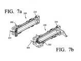
- FIG. 7Ais a side sectional view of the freezing and dispensing barrel of the dispenser of FIG. 1;
- FIG. 7Bis an alternate sectional view of the freezing and dispensing barrel of the dispenser of FIG. 1;
- FIG. 8is a flow diagram illustrating movement of the various liquids through the dispenser of FIG. 1 .
- the present inventionis an apparatus and method for dispensing a frozen alcoholic beverage in which an alcoholic beverage component is mixed with another flavored liquid component and water prior to freezing and dispensing as a frozen beverage product.
- FIG. 1is a perspective view of a preferred frozen alcoholic beverage dispenser 10 made in accordance with the present invention.
- the preferred dispenser 10is portable and preferably comprised of two major components: a base cart 100 and a freezing and dispensing system 200 .
- the base cart 100contains all of the components needed to pump and mix the beverage components prior to freezing to form a single beverage product.
- the freezing and dispensing system 200contains all of the components needed to freeze and then dispense the frozen beverage product.
- FIG. 2is an alternate perspective view of the preferred dispenser 10 with the outer housing of the dispenser 10 removed to illustrate the internal components.
- the base cart 100has a front portion and a rear portion that are separated by a partition 102 .
- the front portionserves as an ingredient cabinet 105 .
- the ingredient cabinet 105is normally accessible through a front door 182 that is preferably secured by a lock 178 .
- the front door 182 of the base cart 100is closed, the contents of the ingredient cabinet 105 are still preferably viewable through a window 180 in the front door 182 of the base cart 100 .
- the rear portion of the base carthouses a mixing panel 101 , the importance of which will be described in detail below.
- the mixing panelis normally accessible through a rear door 184 (as shown in FIG. 1) that is also preferably secured by a lock (not shown).
- the front portion of the base cart 100serves as an ingredient cabinet 105 and includes an alcohol storage rack 104 and a flavorant storage area 103 .
- the flavorant storage area 103is used to store containers containing flavored liquid components, for example, bag-in-box syrup containers (not shown). Indeed, it is contemplated and preferred that multiple containers may be accommodated in the flavorant storage area 103 .
- eachmay be placed in liquid communication with a transfer valve 152 , preferably with common low-density polyethylene tubing.
- a transfer valve 152causes syrup to be drawn from the first container 148 until the syrup in that container 148 is exhausted, at which time the transfer valve 152 automatically switches to allow syrup to be drawn from the second container 150 .
- syrup or a similar flavored liquid componentis carried through low-density polyethylene tubing or a similar conduit from the ingredient cabinet 105 , through the base cart partition 102 , and to the mixing panel 101 where it may be combined with other components to form a single beverage product, as is described in further detail below.
- the alcoholic beverage component of the single beverage productcould be any type of alcoholic beverage, including, for example, bourbon, whiskey, vodka, or tequila. Of course, any brand or type of alcoholic beverage could be used.
- the alcoholic beverage componentis simply referred to as “alcohol.”
- alcoholis preferably stored in the ingredient cabinet 105 through use of an alcohol storage rack 104 , which can hold multiple individual bottles 164 of alcohol.
- the preferred storage rack 104is manufactured and distributed by Berg Company, LLC of Madison, Wis.
- the storage rack 104includes at least one reservoir 168 with multiple openings 172 into the reservoir 168 , each capable of receiving the neck of a bottle 164 .
- a bottle 164can be inverted and inserted into a particular opening such that alcohol is allowed to flow out of the bottle 164 and into the reservoir 168 under the force of gravity.
- there are actually two separate reservoirs 168 , 170each of which is designed to receive three bottles 164 .
- the preferred storage rack 104includes bottle adapters 174 and vertically adjustable bottle brackets 166 associated with each reservoir opening 172 .
- the bottle adapter 174is a flexible sleeve that has a first end that fits over the neck of a bottle 164 , and a second end that fits snuggly into the reservoir opening 172 , thereby ensuring that the bottle 164 is received and held firmly within the opening 172 .
- the vertically adjustable bottle bracket 166includes a vertical stem portion 166 a and a curved arm 166 b extending from and secured to the upper distal end of the stem portion 166 a.
- the vertical stem portion 166 ais mounted adjacent to the reservoir opening 172 , with the curved arm 166 b extending over and adapted to abut the bottom of an inverted bottle 164 .
- the curved arm 166 bcan be positioned to abut and apply downward pressure to the bottom of an inverted bottle 164 that is positioned in the reservoir opening 172 , thereby stabilizing and securing the bottle 164 .
- Alcoholcan flow from the bottles 164 and into the reservoirs 168 , 170 under the force of gravity. Alcohol then flows from the reservoirs 168 , 170 through a single reservoir outlet 176 and into tubing that carries the alcohol out of the ingredient cabinet 105 , through the base cart partition 102 , and to the mixing panel 101 where it may be combined with other beverage ingredients to form a single beverage product.
- the storage rack 104 described abovebe mounted on a sliding platform (e.g., through the use of common drawer slides) that may be pulled forward through the front door 182 of the base cart 100 to facilitate loading and unloading of the bottles 164 .
- the contents of the ingredient cabinet 105including the bottles 164 , are preferably viewable through a window 180 in the front door 182 of the base cart 100 so that a consumer can see what alcoholic beverage is being used in the beverage product, and an operator can see how full or empty the bottles 164 are.
- the window 180is preferably back-lit to enhance the viewing and consumer appeal.
- the storage rack 104allows standard bottles to be used as a source of alcohol, alcohol could be stored in any number of receptacles or containers for subsequent transfer to the mixing panel 101 without departing from the spirit and scope of the present invention.
- the mixing panel 101includes the component feed systems and mixing apparatus that are responsible for producing a single beverage product suitable for processing into a frozen beverage.
- alcoholflows out of the ingredient cabinet 105 , through the base cart partition 102 , and to the mixing panel 101 at an inlet point 112 , as shown in FIGS. 3, 4 and 8 .
- the alcoholis drawn into a gas-driven pump 108 , which is powered by carbon dioxide gas (as is common in beverage dispensing systems).
- a regulator 107preferably supplies gas from a carbon dioxide storage tank 128 to the pump at 60 psi.
- the alcoholis then pumped through a manual shutoff valve 130 , an electric solenoid valve 158 with flow control 118 , and a check valve 122 , the function of each being described in further detail below.
- the alcoholexits the alcohol feed system and enters the mixing area 146 where it is combined with other beverage components for subsequent freezing and dispensing.
- the base cart 100is preferably providing with a structure 128 a for receiving and securing the carbon dioxide tank in front of the mixing panel 110 .
- the flavored liquid component from the ingredient cabinet 105arrives at the mixing panel 101 at an inlet point 114 .
- the flavored liquid componentis drawn into a gas-driven pump 110 , which is powered by carbon dioxide gas.
- the regulator 107preferably supplies gas from the carbon dioxide storage tank 128 to the pump at 60 psi.
- the flavored liquid componentis then pumped through its own set of valves, separate from those of the other component feed systems, including: a manual shutoff valve 132 , an electric solenoid valve 159 with flow control 119 , and a check valve 124 , the function of each being described in further detail below.
- the flavored liquid componentexits the feed system and enters the mixing area 146 where it is combined with other beverage components.
- the carbonated water feed systemreceives water from an external source through an inlet 140 , and the water is drawn through a water booster pump 144 and then pumped through a carbonator 142 where it is supplied with carbon dioxide gas to carbonate the water.
- the regulator 107preferably supplies gas from the carbon dioxide storage tank 128 to the pump at 80 psi.
- the carbonated waterarrives at the mixing panel 101 illustrated in FIGS. 3-4 at an inlet point 116 .
- the carbonated wateris then pumped through its own set of valves, separate from those of the other component feed systems, including: a manual shutoff valve 134 , an electric solenoid valve 160 with flow control, and a check valve 126 , the function of each being described in further detail below.
- the carbonated waterexits the feed system and enters the mixing area 146 where it is combined with other beverage components.
- the manual shutoff valve 130 , 132 , 134 in each of the component feed systemsmay be manually closed to block the flow of a single component.
- the manual shutoff valve 130 of alcoholis closed, alcohol flow will be blocked, but the flow of the flavored liquid component and carbonated water will continue unabated.
- a variety of circumstancescan arise making it desirable to manually block flow of a particular component. For example, if troubleshooting a problem associated with a specific beverage component feed system, the appropriate manual shutoff valves 130 , 132 , 134 could be used to block flow of that particular component or to block flow of the other two components while the problem is investigated.
- the electric solenoid valves 158 , 159 , 160 of the component feed systemsare the primary control valves of the mixing panel 101 as they regulate flow of the beverage components during operation. Referring again to the flow diagram of FIG. 8, when these valves 158 , 159 , 160 are open, the pumps 108 , 110 , 144 move the beverage components through the respective feed systems; when closed, all movement of the beverage components is halted. As will be described further below with respect to the freezing and dispensing system 200 , when the pressure is the freezing barrel 220 drops below 25 psi, the solenoid valves 158 , 159 , 160 open to allow for flow of the beverage components; otherwise, the solenoid valves 158 , 159 , 160 remain closed.
- the pressure in the freezing and dispensing system 200 triggering the opening of the solenoid valves 158 , 159 , 160can be adjusted from about 15-100 psi, but is preferably 25 psi, as described above.
- each flow control 118 , 119 , 120 associated with the electric solenoid valves 158 , 159 , 160 in each of the component feed systemscan be adjusted to alter to flow rate of a particular component.
- the relative flow rate of watercould be adjusted to be greater then the other beverage components.
- Altering flow rates of the various componentscan change the relative ratios of those components, thereby altering the taste and/or the consistency of the final beverage product.
- each flow control 118 , 119 , 120includes a knob 118 a, 119 a, 120 a having an indentation capable of receiving a specialized tool, which can be used to turn the knob.
- knobcauses the opening or restricting of the passageway through the valve, thereby altering the flow rate.
- a semi-permanent devicemay be inserted into the knob indentation to prevent reinsertion of the specialized tool and eliminating the ability to adjust the flow rate. Such a limitation is desirable in the ensuring that alcohol content is not easily manipulated.
- each component feed systemprevents the back flow of the respective beverage components through the solenoid valves 158 , 159 , 160 .
- the componentsare introduced into and mixed in a common conduit or a mixing area 146 .
- the mixed beveragethen exits the base cart 100 at an outlet point 136 and is introduced into the freezing and dispensing system 200 .
- the base cart and the freezing and dispensing systemare separate components that may be mounted together or in different locations to allow for remote dispensing. If the two components are mounted in different locations, the mixed beverage would exit the base cart 100 at an outlet point 136 and flow through tubing before being introduced into the remotely located freezing and dispensing system 200 .
- the preferred freezing and dispensing system 200contains all of the components needed to freeze and dispense a frozen alcoholic beverage with a desired consistency.
- the system 200includes a standard freezer that is commonly used in frozen beverage dispensers, such as the freezer used in a Model 3311 Standard Beverage Freezer manufactured and distributed by Grindmaster Crathco Systems, Inc. of Louisville, Ky. (the assignee of the present invention). To the extent that the components of the Model 3311 Standard Beverage Freezer are used without modification in the preferred embodiment of the invention, they are not described in detail.
- the compressor, condenser, condenser fan, evaporator, freezing and dispensing barrel 220 with rotatable scraper mounted inside (enclosed in insulation 222 in FIGS. 2 - 3 ), motor used to drive the scraper, and control system for the motorare all standard.
- Such a standard freezeris also described in co-pending U.S. application Ser. No. 10/000,793, which is incorporated herein by reference.
- the freezing and dispensing system 200also includes an accumulator 210 , which is best described with reference to FIGS. 5, 6 , and 8 .
- the accumulator 210receives mixed beverage from the mixing area 146 at an inlet 212 .
- the accumulator 210also has an outlet 216 in liquid communication with the freezing and dispensing barrel 220 , as best shown in FIGS. 7A-7B to introduce mixed beverage into the freezing and dispensing barrel 220 .
- the preferred freezing and dispensing barrel 220includes a dispensing valve 202 at a distal end thereof operated by a handle 204 .
- the dispensing handle 204When the dispensing handle 204 is manually activated, it causes the dispensing valve 202 to open.
- the pressure in both the freezing and dispensing barrel 220 and the accumulator 210is higher than atmospheric pressure; thus, when the dispensing valve 202 is opened, the frozen beverage product is expelled from through the dispensing valve 202 and out of the dispenser 10 .
- a volume of mixed beverageis drawn through the accumulator 210 and into the freezing and dispensing barrel 220 for freezing, resulting in a drop in pressure.
- a pressure switch 214interposed between the accumulator 210 and the freezing and dispensing barrel 220 , is activated when the pressure falls below approximately 20-27 psi, thus causing the electric solenoid valves 158 , 159 , 160 of the component feed systems to open, thereby replenishing the supply of the mixed beverage to the accumulator 210 .
- the solenoid valves 158 , 159 , 160remain open until the pressure returns to approximately 20-27 psi.
- the preferred dispenser 10is also provided with various switches, collectively referred to as “mix-out” switches, that are activated when a particular component has run out.
- a float switch 106is configured to close when there is no more alcohol in the reservoirs 168 , 170 of the alcohol storage rack 104 .
- a pressure switch 154is located between the pump 110 and the manual shutoff valve 132 in the flavored liquid component feed system that is activated when the contents of the liquid component containers 148 , 150 are depleted
- a pressure switch 156is located between the water inlet 140 and the water booster pump 144 that is activated when the water supply is cut off.
- a pressure switch 143is configured to activate when the carbon dioxide supply from the carbon dioxide tank 128 is cut off. If one of these mix-out switches 106 , 154 , 156 , 143 is activated, an appropriate signal is sent to the associated solenoid valve to prevent the valves from opening. Indeed, it is contemplated and preferred that all of the solenoid valves 158 , 159 , 160 would be prevented from opening, effectively preventing any further flow of any of the beverage components.
- activation of one or more of the mix-out switches 106 , 154 , 156 , 143also trigger an audio alarm or a visual alarm, such as a light on the front panel of the dispenser 10 , signaling that a beverage component needs to be replenished.
- the preferred dispenser 10 described hereinallows for sampling of the mixed beverage or any components thereof prior to the freezing process.
- samples for analysiscan be collected from a sample port 139 that is in liquid communication with the mixing area 146 . Samples are allowed to flow through the sample port 139 when a manual product-sampling valve 138 is opened. If a sample of only one component is desired, the manual shutoff valves 130 , 132 , 134 associated with the other two components can be closed during the sampling process.
- a timermay also be incorporated into the sampling system.
- an electronic timeractivated using a switch 123 located near the mixing panel 101 , as illustrated in FIG. 3, causes the electric solenoid valves 158 , 159 , 160 to open for a fixed period of time, allowing the beverage components to flow through of the respective feed systems, through the opened product sampling valve 138 , and out of the sampling port 139 into a collection container of some sort.
- a separate sample of each ingredientcan be collected.
- the volumes of each component samplecan be measured and used to calculate ratios of one component to another.
- maintenance of traditional frozen beverage dispensersincludes collecting samples for Brix analysis, i.e., percentage of sugar in water.
- Brix analysisi.e., percentage of sugar in water.
- the appropriate Brix reading for a sugar and water mixture in a frozen beverageis about 15.
- Brix analysis of an alcoholic beverage mixturecan not be made using traditional refractometers because the alcohol clouds the measurement causing an artificial reading.
- the sampling system of the present inventionallows both Brix analysis, as well as alcohol ratio analysis.
- the alcohol manual shutoff valve 130may be closed to block alcohol flow. Then, when the electronic timer is activated to open the electric solenoid valves 158 , 159 , 160 , a mixture will be dispensed from the sample port 139 containing only water and the flavored liquid component (e.g., syrup). Because this mixture will contain no alcohol, a traditional refractometer can be used to obtain a Brix reading on the water/syrup mixture.
- the various manual shutoff valves 130 , 132 , 134can be adjusted to allow a separate sample of water and syrup to be collected in two consecutive activations of the timer. The volumes of the two samples can then be used to calculate the water to sugar ratio.
- a variation of this second methodcan be used to measure the alcohol ratio, a measurement that is impossible to obtain using traditional refractometers.
- the syrup manual shutoff valve 132 and the carbonated water manual shutoff valve 134can be closed to block flow of syrup and water so that only alcohol will flow out of the sample port 139 when the electronic timer is activated opening the electric solenoid valves 158 , 159 , 160 . Similar samples of the other components can then be taken, and a volumetric ratio of alcohol to the other components can then be determined.
Landscapes
- Life Sciences & Earth Sciences (AREA)
- Chemical & Material Sciences (AREA)
- Engineering & Computer Science (AREA)
- Food Science & Technology (AREA)
- Polymers & Plastics (AREA)
- Devices For Dispensing Beverages (AREA)
Abstract
Description
Claims (29)
Priority Applications (1)
| Application Number | Priority Date | Filing Date | Title |
|---|---|---|---|
| US10/295,722US6745592B1 (en) | 2001-11-01 | 2002-11-15 | Apparatus and method for dispensing a frozen alcoholic beverage |
Applications Claiming Priority (3)
| Application Number | Priority Date | Filing Date | Title |
|---|---|---|---|
| US10/000,793US6622510B2 (en) | 2000-11-01 | 2001-11-01 | Frozen beer product, method and apparatus |
| US33323001P | 2001-11-16 | 2001-11-16 | |
| US10/295,722US6745592B1 (en) | 2001-11-01 | 2002-11-15 | Apparatus and method for dispensing a frozen alcoholic beverage |
Related Parent Applications (1)
| Application Number | Title | Priority Date | Filing Date |
|---|---|---|---|
| US10/000,793Continuation-In-PartUS6622510B2 (en) | 2000-11-01 | 2001-11-01 | Frozen beer product, method and apparatus |
Publications (1)
| Publication Number | Publication Date |
|---|---|
| US6745592B1true US6745592B1 (en) | 2004-06-08 |
Family
ID=32328481
Family Applications (1)
| Application Number | Title | Priority Date | Filing Date |
|---|---|---|---|
| US10/295,722Expired - Fee RelatedUS6745592B1 (en) | 2001-11-01 | 2002-11-15 | Apparatus and method for dispensing a frozen alcoholic beverage |
Country Status (1)
| Country | Link |
|---|---|
| US (1) | US6745592B1 (en) |
Cited By (37)
| Publication number | Priority date | Publication date | Assignee | Title |
|---|---|---|---|---|
| EP1738652A3 (en)* | 2005-06-27 | 2007-02-14 | Imi Cornelius (Uk) Limited | Frozen beverages |
| GB2432354A (en)* | 2005-11-03 | 2007-05-23 | Scottish & Newcastle Plc | Beverage dispenser |
| US20080054837A1 (en)* | 2006-03-06 | 2008-03-06 | Beavis Russell H | System and method for generating a drive signal |
| US20080073610A1 (en)* | 1997-08-22 | 2008-03-27 | Manning Casey P | Stopcock valve |
| US20080142548A1 (en)* | 2006-12-13 | 2008-06-19 | Frozen Beverage Services Of California, Inc. | Method and Apparatus for Combination and Delivery of Beverages for Consumption |
| US20080179346A1 (en)* | 2007-01-26 | 2008-07-31 | Kevin Downey | Method and assembly for dispensing semi-frozen beverages |
| US20090159612A1 (en)* | 2007-09-06 | 2009-06-25 | Deka Research & Development Corp. | Product dispensing system |
| US20090277516A1 (en)* | 2006-03-06 | 2009-11-12 | Felix Winkler | Product Dispensing System |
| US20100005903A1 (en)* | 2007-09-06 | 2010-01-14 | Deka Products Limited Partnership | Product Dispensing System |
| WO2010130021A1 (en)* | 2009-05-13 | 2010-11-18 | Keg Switch Technologies Llc | A valve apparatus for selectively dispensing liquid from a plurality of sources |
| USD691207S1 (en)* | 2012-02-20 | 2013-10-08 | Societe Des Produits Nestle S.A. | Beverage machine support |
| JP2015091713A (en)* | 2013-10-01 | 2015-05-14 | アサヒビール株式会社 | Automatic liquid injection apparatus |
| US9328957B1 (en) | 2014-05-29 | 2016-05-03 | Darin Feinstein | Sidewalk accessible food service stand |
| US20160222332A1 (en)* | 2015-01-30 | 2016-08-04 | Anheuser-Busch Inbev S.A. | Methods, appliances, and systems for preparing a beverage from a base liquid and an ingredient |
| US20160229675A1 (en)* | 2015-02-09 | 2016-08-11 | Fbd Partnership, Lp | Multi-flavor food and/or beverage dispenser |
| US20170094990A1 (en)* | 2015-10-02 | 2017-04-06 | Pw Stoelting, L.L.C. | Frozen beverage dispenser |
| US20170292100A1 (en)* | 2016-04-08 | 2017-10-12 | Bryan Butte | Accelerated Aging of Alcohol Drinks |
| US20170347690A1 (en)* | 2014-12-30 | 2017-12-07 | Unitec S.P.A. | Improved apparatus for dispensing and mixing cold beverages |
| US9894912B2 (en) | 2015-06-04 | 2018-02-20 | Blendtec, Inc. | Chilled product post-processing apparatus |
| US10071898B2 (en) | 2015-04-10 | 2018-09-11 | Comedlius, Inc. | Multiple flavor beverage dispenser |
| US10252904B2 (en) | 2016-09-12 | 2019-04-09 | Cornelius, Inc. | Systems and methods of custom condiment dispensing |
| US10315236B2 (en) | 2016-10-25 | 2019-06-11 | Cornelius, Inc. | Systems and methods of food dispenser cleaning |
| US10493412B2 (en) | 2015-05-12 | 2019-12-03 | Blendtec, Inc. | Blending systems and methods with blade assembly dampening |
| US10507479B2 (en) | 2016-11-01 | 2019-12-17 | Cornelius, Inc. | Dispensing nozzle |
| WO2020191221A1 (en)* | 2019-03-21 | 2020-09-24 | Taylor Commercial Foodservice, Llc | Frozen beverage machine |
| EP3585722A4 (en)* | 2018-04-27 | 2021-06-02 | Taylor Commercial Foodservice, LLC | Apparatus and method for fluid flow measurement |
| US11076613B2 (en)* | 2016-10-24 | 2021-08-03 | The Vollrath Company, L.L.C. | Frozen food product dispensing machine including mixing manifold |
| US11135345B2 (en) | 2017-05-10 | 2021-10-05 | Fresenius Medical Care Holdings, Inc. | On demand dialysate mixing using concentrates |
| US11208314B2 (en) | 2015-01-30 | 2021-12-28 | Anheuser-Busch Inbev S.A. | Pressurized beverage concentrates and appliances and methods for producing beverages therefrom |
| US11427462B2 (en) | 2007-09-06 | 2022-08-30 | Deka Products Limited Partnership | Product dispensing system |
| US11504458B2 (en) | 2018-10-17 | 2022-11-22 | Fresenius Medical Care Holdings, Inc. | Ultrasonic authentication for dialysis |
| US11634311B2 (en) | 2007-09-06 | 2023-04-25 | Deka Products Limited Partnership | Product dispensing system |
| US11655806B2 (en) | 2007-09-06 | 2023-05-23 | Deka Products Limited Partnership | Product dispensing system |
| US11661329B2 (en) | 2006-03-06 | 2023-05-30 | Deka Products Limited Partnership | System and method for generating a drive signal |
| US11748827B2 (en) | 2018-08-06 | 2023-09-05 | Marmon Foodservice Technologies, Inc. | Order fulfillment system |
| US11906988B2 (en) | 2006-03-06 | 2024-02-20 | Deka Products Limited Partnership | Product dispensing system |
| US12135019B2 (en) | 2007-09-06 | 2024-11-05 | Deka Products Limited Partnership | Product dispensing system |
Citations (19)
| Publication number | Priority date | Publication date | Assignee | Title |
|---|---|---|---|---|
| US2194775A (en) | 1937-09-22 | 1940-03-26 | Donald Colvin | Beverage dispenser and carbonator |
| US3359748A (en) | 1966-03-25 | 1967-12-26 | Jack J Booth | Slush co2 control |
| US3379029A (en) | 1966-04-29 | 1968-04-23 | Gen Electric | Auto defrost refrigerator |
| US3979024A (en) | 1974-12-27 | 1976-09-07 | The Vendo Company | Ingredient temperature stabilization apparatus for post-mix beverage dispensing machines |
| US3995770A (en) | 1975-03-19 | 1976-12-07 | Beatrice Foods Co. | Apparatus for dispensing beverages |
| US4022031A (en) | 1973-05-02 | 1977-05-10 | Calim Thomas F | Method for producing frozen confection |
| US4201558A (en) | 1978-12-01 | 1980-05-06 | Beatrice Foods Co. | Method and apparatus for preparing and dispensing a semi-frozen product |
| US4440795A (en) | 1981-02-06 | 1984-04-03 | Miller Brewing Company | Process for the preparation of a stable citrus flavored malt beverage |
| US4448036A (en) | 1981-10-30 | 1984-05-15 | Gerlach Industries Inc. | Refrigeration system |
| US4704877A (en)* | 1986-10-02 | 1987-11-10 | Cbi Industries, Inc. | Apparatus and method of freezing a feed liquid |
| US4869396A (en) | 1987-08-24 | 1989-09-26 | Kirin Beer Kabushiki Kaisha | Draught beer dispensing system |
| US5304384A (en) | 1993-03-23 | 1994-04-19 | Labatt Brewing Company Limited | Improvements in production of fermented malt beverages |
| US5463877A (en) | 1994-07-14 | 1995-11-07 | Wilch Manufacturing, Inc. | Dispenser having edge-lighted, transparent valve for product display |
| US5615559A (en) | 1995-03-01 | 1997-04-01 | Apv Crepaco Inc. | Method and apparatus for recirculating product in a refrigeration system |
| US5869114A (en) | 1994-03-18 | 1999-02-09 | Labatt Brewing Company Limited | Production of fermented malt beverages |
| US20020083730A1 (en) | 2000-11-01 | 2002-07-04 | Giroux Mark S. | Frozen beer product, method and apparatus |
| US6434966B1 (en)* | 1999-10-01 | 2002-08-20 | Kan-Pak, L.L.C. | Self-contained liquid storage, delivery, and automatic fill apparatus and method |
| US6511693B2 (en)* | 2000-02-15 | 2003-01-28 | Softpac Industries, Inc. | Frozen slushy in a squeezable pouch |
| US20030161923A1 (en)* | 2000-09-22 | 2003-08-28 | Holland Joseph Eugene | Frozen beverage apparatus |
- 2002
- 2002-11-15USUS10/295,722patent/US6745592B1/ennot_activeExpired - Fee Related
Patent Citations (19)
| Publication number | Priority date | Publication date | Assignee | Title |
|---|---|---|---|---|
| US2194775A (en) | 1937-09-22 | 1940-03-26 | Donald Colvin | Beverage dispenser and carbonator |
| US3359748A (en) | 1966-03-25 | 1967-12-26 | Jack J Booth | Slush co2 control |
| US3379029A (en) | 1966-04-29 | 1968-04-23 | Gen Electric | Auto defrost refrigerator |
| US4022031A (en) | 1973-05-02 | 1977-05-10 | Calim Thomas F | Method for producing frozen confection |
| US3979024A (en) | 1974-12-27 | 1976-09-07 | The Vendo Company | Ingredient temperature stabilization apparatus for post-mix beverage dispensing machines |
| US3995770A (en) | 1975-03-19 | 1976-12-07 | Beatrice Foods Co. | Apparatus for dispensing beverages |
| US4201558A (en) | 1978-12-01 | 1980-05-06 | Beatrice Foods Co. | Method and apparatus for preparing and dispensing a semi-frozen product |
| US4440795A (en) | 1981-02-06 | 1984-04-03 | Miller Brewing Company | Process for the preparation of a stable citrus flavored malt beverage |
| US4448036A (en) | 1981-10-30 | 1984-05-15 | Gerlach Industries Inc. | Refrigeration system |
| US4704877A (en)* | 1986-10-02 | 1987-11-10 | Cbi Industries, Inc. | Apparatus and method of freezing a feed liquid |
| US4869396A (en) | 1987-08-24 | 1989-09-26 | Kirin Beer Kabushiki Kaisha | Draught beer dispensing system |
| US5304384A (en) | 1993-03-23 | 1994-04-19 | Labatt Brewing Company Limited | Improvements in production of fermented malt beverages |
| US5869114A (en) | 1994-03-18 | 1999-02-09 | Labatt Brewing Company Limited | Production of fermented malt beverages |
| US5463877A (en) | 1994-07-14 | 1995-11-07 | Wilch Manufacturing, Inc. | Dispenser having edge-lighted, transparent valve for product display |
| US5615559A (en) | 1995-03-01 | 1997-04-01 | Apv Crepaco Inc. | Method and apparatus for recirculating product in a refrigeration system |
| US6434966B1 (en)* | 1999-10-01 | 2002-08-20 | Kan-Pak, L.L.C. | Self-contained liquid storage, delivery, and automatic fill apparatus and method |
| US6511693B2 (en)* | 2000-02-15 | 2003-01-28 | Softpac Industries, Inc. | Frozen slushy in a squeezable pouch |
| US20030161923A1 (en)* | 2000-09-22 | 2003-08-28 | Holland Joseph Eugene | Frozen beverage apparatus |
| US20020083730A1 (en) | 2000-11-01 | 2002-07-04 | Giroux Mark S. | Frozen beer product, method and apparatus |
Cited By (66)
| Publication number | Priority date | Publication date | Assignee | Title |
|---|---|---|---|---|
| US20080073610A1 (en)* | 1997-08-22 | 2008-03-27 | Manning Casey P | Stopcock valve |
| EP1738652A3 (en)* | 2005-06-27 | 2007-02-14 | Imi Cornelius (Uk) Limited | Frozen beverages |
| US20080282722A1 (en)* | 2005-11-03 | 2008-11-20 | Clive Justin Edmonds | Methods and Apparatus for Dispensing Beverages |
| GB2432354A (en)* | 2005-11-03 | 2007-05-23 | Scottish & Newcastle Plc | Beverage dispenser |
| GB2432354B (en)* | 2005-11-03 | 2009-06-03 | Scottish & Newcastle Plc | Methods and apparatus for dispenisng beverages |
| US9146564B2 (en)* | 2006-03-06 | 2015-09-29 | Deka Products Limited Partnership | Product dispensing system |
| US20150160660A1 (en)* | 2006-03-06 | 2015-06-11 | Deka Products Limited Partnership | Product Dispensing System |
| US11429120B2 (en) | 2006-03-06 | 2022-08-30 | Deka Products Limited Partnership | Product dispensing system |
| US20090277516A1 (en)* | 2006-03-06 | 2009-11-12 | Felix Winkler | Product Dispensing System |
| US11661329B2 (en) | 2006-03-06 | 2023-05-30 | Deka Products Limited Partnership | System and method for generating a drive signal |
| US20100206400A2 (en)* | 2006-03-06 | 2010-08-19 | Felix Winkler | Product Dispensing System |
| US11906988B2 (en) | 2006-03-06 | 2024-02-20 | Deka Products Limited Partnership | Product dispensing system |
| US11975960B2 (en) | 2006-03-06 | 2024-05-07 | Deka Products Limited Partnership | System and method for generating a drive signal |
| US7905373B2 (en) | 2006-03-06 | 2011-03-15 | Deka Products Limited Partnership | System and method for generating a drive signal |
| US20080054837A1 (en)* | 2006-03-06 | 2008-03-06 | Beavis Russell H | System and method for generating a drive signal |
| US9891633B2 (en)* | 2006-03-06 | 2018-02-13 | Deka Products Limited Partnership | Product dispensing system |
| US20080142548A1 (en)* | 2006-12-13 | 2008-06-19 | Frozen Beverage Services Of California, Inc. | Method and Apparatus for Combination and Delivery of Beverages for Consumption |
| US20080179346A1 (en)* | 2007-01-26 | 2008-07-31 | Kevin Downey | Method and assembly for dispensing semi-frozen beverages |
| US8322570B2 (en) | 2007-09-06 | 2012-12-04 | Deka Products Limited Partnership | Product dispensing system |
| US8087303B2 (en) | 2007-09-06 | 2012-01-03 | Deka Products Limited Partnership | Product dispensing system |
| US20100005903A1 (en)* | 2007-09-06 | 2010-01-14 | Deka Products Limited Partnership | Product Dispensing System |
| US11738989B2 (en) | 2007-09-06 | 2023-08-29 | Deka Products Limited Partnership | Product dispensing system |
| US11365107B2 (en) | 2007-09-06 | 2022-06-21 | Deka Products Limited Partnership | Product dispensing system |
| US11655806B2 (en) | 2007-09-06 | 2023-05-23 | Deka Products Limited Partnership | Product dispensing system |
| US11427462B2 (en) | 2007-09-06 | 2022-08-30 | Deka Products Limited Partnership | Product dispensing system |
| US20090159612A1 (en)* | 2007-09-06 | 2009-06-25 | Deka Research & Development Corp. | Product dispensing system |
| US20110011888A2 (en)* | 2007-09-06 | 2011-01-20 | Russell Beavis | Product dispensing system |
| US12338116B2 (en) | 2007-09-06 | 2025-06-24 | Deka Products Limited Partneship | Product dispensing system |
| US11634311B2 (en) | 2007-09-06 | 2023-04-25 | Deka Products Limited Partnership | Product dispensing system |
| US8783513B2 (en)* | 2007-09-06 | 2014-07-22 | Deka Products Limited Partnership | Product dispensing system |
| US12135019B2 (en) | 2007-09-06 | 2024-11-05 | Deka Products Limited Partnership | Product dispensing system |
| US12372987B2 (en) | 2009-05-07 | 2025-07-29 | Deka Products Limited Partnership | Product dispensing system |
| WO2010130021A1 (en)* | 2009-05-13 | 2010-11-18 | Keg Switch Technologies Llc | A valve apparatus for selectively dispensing liquid from a plurality of sources |
| US8561842B2 (en) | 2009-05-13 | 2013-10-22 | Keg Switch Technologies, LLC | Valve apparatus for selectively dispensing liquid from a plurality of sources |
| USD691207S1 (en)* | 2012-02-20 | 2013-10-08 | Societe Des Produits Nestle S.A. | Beverage machine support |
| JP2015091713A (en)* | 2013-10-01 | 2015-05-14 | アサヒビール株式会社 | Automatic liquid injection apparatus |
| US9328957B1 (en) | 2014-05-29 | 2016-05-03 | Darin Feinstein | Sidewalk accessible food service stand |
| AU2015373133B2 (en)* | 2014-12-30 | 2019-08-29 | Unitec S.P.A. | Apparatus for dispensing mixed beverages from frozen ingredients |
| US20170347690A1 (en)* | 2014-12-30 | 2017-12-07 | Unitec S.P.A. | Improved apparatus for dispensing and mixing cold beverages |
| US10624371B2 (en)* | 2014-12-30 | 2020-04-21 | Unitec S.P.A. | Apparatus for dispensing and mixing cold beverages |
| US20160222332A1 (en)* | 2015-01-30 | 2016-08-04 | Anheuser-Busch Inbev S.A. | Methods, appliances, and systems for preparing a beverage from a base liquid and an ingredient |
| US11208314B2 (en) | 2015-01-30 | 2021-12-28 | Anheuser-Busch Inbev S.A. | Pressurized beverage concentrates and appliances and methods for producing beverages therefrom |
| US20190098914A1 (en)* | 2015-02-09 | 2019-04-04 | Fbd Partnership, Lp | Multi-flavor food and/or beverage dispenser |
| US10512276B2 (en)* | 2015-02-09 | 2019-12-24 | Fbd Partnership, Lp | Multi-flavor food and/or beverage dispenser |
| US20160229675A1 (en)* | 2015-02-09 | 2016-08-11 | Fbd Partnership, Lp | Multi-flavor food and/or beverage dispenser |
| US11252976B2 (en)* | 2015-02-09 | 2022-02-22 | Fbd Partnership, Lp | Multi-flavor food and/or beverage dispenser |
| US10071898B2 (en) | 2015-04-10 | 2018-09-11 | Comedlius, Inc. | Multiple flavor beverage dispenser |
| US10961103B2 (en) | 2015-04-10 | 2021-03-30 | Cornelius, Inc. | Multiple flavor beverage dispenser |
| US10351408B2 (en) | 2015-04-10 | 2019-07-16 | Cornelius, Inc. | Multiple flavor beverage dispenser |
| US10493412B2 (en) | 2015-05-12 | 2019-12-03 | Blendtec, Inc. | Blending systems and methods with blade assembly dampening |
| US9894912B2 (en) | 2015-06-04 | 2018-02-20 | Blendtec, Inc. | Chilled product post-processing apparatus |
| US20170094990A1 (en)* | 2015-10-02 | 2017-04-06 | Pw Stoelting, L.L.C. | Frozen beverage dispenser |
| US10743563B2 (en)* | 2015-10-02 | 2020-08-18 | The Vollrath Company, L.L.C. | Frozen beverage dispenser |
| US20170292100A1 (en)* | 2016-04-08 | 2017-10-12 | Bryan Butte | Accelerated Aging of Alcohol Drinks |
| US10196595B2 (en)* | 2016-04-08 | 2019-02-05 | Bryan Butte | Accelerated aging of alcohol drinks |
| US10252904B2 (en) | 2016-09-12 | 2019-04-09 | Cornelius, Inc. | Systems and methods of custom condiment dispensing |
| US10947106B2 (en) | 2016-09-12 | 2021-03-16 | Cornelius, Inc. | Systems and methods of custom condiment dispensing |
| US11076613B2 (en)* | 2016-10-24 | 2021-08-03 | The Vollrath Company, L.L.C. | Frozen food product dispensing machine including mixing manifold |
| US10315236B2 (en) | 2016-10-25 | 2019-06-11 | Cornelius, Inc. | Systems and methods of food dispenser cleaning |
| US10507479B2 (en) | 2016-11-01 | 2019-12-17 | Cornelius, Inc. | Dispensing nozzle |
| US11752246B2 (en) | 2017-05-10 | 2023-09-12 | Fresenius Medical Care Holdings, Inc. | On demand dialysate mixing using concentrates |
| US11135345B2 (en) | 2017-05-10 | 2021-10-05 | Fresenius Medical Care Holdings, Inc. | On demand dialysate mixing using concentrates |
| EP3585722A4 (en)* | 2018-04-27 | 2021-06-02 | Taylor Commercial Foodservice, LLC | Apparatus and method for fluid flow measurement |
| US11748827B2 (en) | 2018-08-06 | 2023-09-05 | Marmon Foodservice Technologies, Inc. | Order fulfillment system |
| US11504458B2 (en) | 2018-10-17 | 2022-11-22 | Fresenius Medical Care Holdings, Inc. | Ultrasonic authentication for dialysis |
| WO2020191221A1 (en)* | 2019-03-21 | 2020-09-24 | Taylor Commercial Foodservice, Llc | Frozen beverage machine |
Similar Documents
| Publication | Publication Date | Title |
|---|---|---|
| US6745592B1 (en) | Apparatus and method for dispensing a frozen alcoholic beverage | |
| US4932561A (en) | Beverage cooling and dispensing apparatus | |
| US4440318A (en) | Beverage dispenser | |
| US8403179B1 (en) | Automatic draw valve freezer with multiple flavor option | |
| US5056686A (en) | Beverage dispensing system | |
| EP0278773B1 (en) | Beverage dispensing system | |
| US5725125A (en) | Method of and means for providing multiple flavored beverages from a dispensing valve from a beverage dispensing unit | |
| US4903862A (en) | Soft drink dispenser | |
| US5033645A (en) | Carbonation system for soft drink dispenser | |
| US7337924B2 (en) | Refrigerator which removably holds a drink supply container having a valve co-acting with an engager | |
| US6766656B1 (en) | Beverage dispensing apparatus | |
| US7416097B2 (en) | Drink supply container valve assembly | |
| US4687120A (en) | Method and apparatus for dispensing cold beverage | |
| US6896159B2 (en) | Beverage dispensing apparatus having fluid director | |
| US5000357A (en) | Soft drink dispenser | |
| US3460713A (en) | Method of dispensing a refrigerated beverage | |
| US20020083730A1 (en) | Frozen beer product, method and apparatus | |
| IE44156B1 (en) | Process and apparatus for preparing and dispensing carbonated liquids | |
| US6434966B1 (en) | Self-contained liquid storage, delivery, and automatic fill apparatus and method | |
| GB2160847A (en) | Tapping device for postmixed drinks | |
| US6349853B1 (en) | Hygienic beverage machine | |
| EP2158153A2 (en) | Beverage carousel dispensing device suitable for tapping multiple self-emptying beverage containers | |
| NZ206710A (en) | Cold beverage dispenser;functions powered by compressed gas | |
| WO2024006083A1 (en) | Mechanical carbonated beverage dispensing system | |
| CA2255339A1 (en) | Beverage dispensing apparatus |
Legal Events
| Date | Code | Title | Description |
|---|---|---|---|
| AS | Assignment | Owner name:GRINDMASTER CRATHCO SYSTEMS, INC., KENTUCKY Free format text:ASSIGNMENT OF ASSIGNORS INTEREST;ASSIGNORS:EDRINGTON, MICHAEL J.;SIPP, RICHARD L.;REEL/FRAME:013505/0260 Effective date:20021115 | |
| AS | Assignment | Owner name:BANK ONE, NA, KENTUCKY Free format text:SECURITY INTEREST;ASSIGNOR:GRINDMASTER CRATHCO SYSTEMS, INC.;REEL/FRAME:014797/0001 Effective date:20030924 | |
| CC | Certificate of correction | ||
| AS | Assignment | Owner name:PNC BANK, PENNSYLVANIA Free format text:SECURITY AGREEMENT;ASSIGNOR:GRINDMASTER CORPORATION;REEL/FRAME:017507/0919 Effective date:20060322 | |
| FPAY | Fee payment | Year of fee payment:4 | |
| AS | Assignment | Owner name:GRINDMASTER CORPORATION, MICHIGAN Free format text:TERMINATION OF SECURITY AGREEMENT;ASSIGNOR:PNC BANK, NATIONAL ASSOCIATION;REEL/FRAME:023180/0455 Effective date:20090819 | |
| AS | Assignment | Owner name:RBS BUSINESS CAPITAL, A DIVISION OF RBS ASSET FINA Free format text:SECURITY AGREEMENT;ASSIGNOR:GRINDMASTER CORPORATION;REEL/FRAME:023355/0952 Effective date:20090917 | |
| AS | Assignment | Owner name:FIRST NEW ENGLAND CAPITAL III, LP, AS COLLATERAL A Free format text:SECURITY AGREEMENT;ASSIGNOR:GRINDMASTER CORPORATION;REEL/FRAME:023401/0680 Effective date:20090917 | |
| AS | Assignment | Owner name:GRINDMASTER CORPORATION (FORMERLY GRINDMASTER CRAT Free format text:RELEASE BY SECURED PARTY;ASSIGNOR:JPMORGAN CHASE BANK, NATIONAL ASSOCIATION;REEL/FRAME:023438/0490 Effective date:20091008 Owner name:JPMORGAN CHASE BANK, NATIONAL ASSOCIATION, NEW YOR Free format text:MERGER;ASSIGNORS:BANK ONE, NATIONAL ASSOCIATION, CHICAGO, ILLINOIS (CHARTER NO. 8);BANK ONE, NATIONAL ASSOCIATION, COLUMBUS, OHIO (CHARTER NO. 7621);REEL/FRAME:023438/0474 Effective date:20041113 | |
| AS | Assignment | Owner name:WEBSTER BANK, NATIONAL ASSOCIATION, CONNECTICUT Free format text:SECURITY AGREEMENT;ASSIGNORS:CECILWARE CORPORATION;GRINDMASTER CORPORATION;REEL/FRAME:025227/0661 Effective date:20101029 | |
| FPAY | Fee payment | Year of fee payment:8 | |
| AS | Assignment | Owner name:GRINDMASTER CORPORATION, KENTUCKY Free format text:RELEASE BY SECURED PARTY;ASSIGNOR:RBS BUSINESS CAPITAL, A DIVISION OF RBS ASSET FINANCE, INC.;REEL/FRAME:034137/0017 Effective date:20101020 | |
| AS | Assignment | Owner name:GRINDMASTER CORPORATION, KENTUCKY Free format text:RELEASE BY SECURED PARTY;ASSIGNOR:FIRST NEW ENGLAND CAPITAL III, L.P.;REEL/FRAME:034209/0653 Effective date:20141119 | |
| AS | Assignment | Owner name:FIDUS MEZZANINE CAPITAL, L.P., ILLINOIS Free format text:SECURITY INTEREST;ASSIGNORS:CECILWARE CORPORATION;GRINDMASTER CORPORATION;REEL/FRAME:034230/0488 Effective date:20141031 | |
| REMI | Maintenance fee reminder mailed | ||
| LAPS | Lapse for failure to pay maintenance fees | ||
| STCH | Information on status: patent discontinuation | Free format text:PATENT EXPIRED DUE TO NONPAYMENT OF MAINTENANCE FEES UNDER 37 CFR 1.362 | |
| FP | Lapsed due to failure to pay maintenance fee | Effective date:20160608 | |
| AS | Assignment | Owner name:GRINDMASTER CORPORATION, KENTUCKY Free format text:RELEASE BY SECURED PARTY;ASSIGNOR:WEBSTER BANK;REEL/FRAME:041470/0526 Effective date:20170228 Owner name:CECILWARE CORPORATION, KENTUCKY Free format text:RELEASE BY SECURED PARTY;ASSIGNOR:WEBSTER BANK;REEL/FRAME:041470/0526 Effective date:20170228 Owner name:CECILWARE CORPORATION, KENTUCKY Free format text:RELEASE BY SECURED PARTY;ASSIGNOR:FIDUS MEZZANINE CAPITAL, L.P.;REEL/FRAME:041470/0647 Effective date:20170228 Owner name:GRINDMASTER CORPORATION, KENTUCKY Free format text:RELEASE BY SECURED PARTY;ASSIGNOR:FIDUS MEZZANINE CAPITAL, L.P.;REEL/FRAME:041470/0647 Effective date:20170228 |