US6744887B1 - Acoustic echo processing system - Google Patents
Acoustic echo processing systemDownload PDFInfo
- Publication number
- US6744887B1 US6744887B1US09/412,293US41229399AUS6744887B1US 6744887 B1US6744887 B1US 6744887B1US 41229399 AUS41229399 AUS 41229399AUS 6744887 B1US6744887 B1US 6744887B1
- Authority
- US
- United States
- Prior art keywords
- filter
- signal
- microphone
- loud speaker
- echoes
- Prior art date
- Legal status (The legal status is an assumption and is not a legal conclusion. Google has not performed a legal analysis and makes no representation as to the accuracy of the status listed.)
- Expired - Fee Related
Links
- 238000012545processingMethods0.000titleclaimsdescription21
- 230000003044adaptive effectEffects0.000claimsabstractdescription42
- 230000004044responseEffects0.000claimsabstractdescription38
- 238000000034methodMethods0.000claimsabstractdescription30
- 238000002592echocardiographyMethods0.000claimsdescription34
- 230000008569processEffects0.000claimsdescription17
- 230000015654memoryEffects0.000claimsdescription15
- 238000001228spectrumMethods0.000claimsdescription12
- 230000000694effectsEffects0.000claimsdescription5
- 238000001914filtrationMethods0.000claimsdescription5
- 230000008878couplingEffects0.000abstractdescription5
- 238000010168coupling processMethods0.000abstractdescription5
- 238000005859coupling reactionMethods0.000abstractdescription5
- 239000002131composite materialSubstances0.000abstract1
- 238000005070samplingMethods0.000description7
- 230000003595spectral effectEffects0.000description7
- 230000006870functionEffects0.000description4
- 230000006978adaptationEffects0.000description3
- 238000004458analytical methodMethods0.000description3
- 238000013459approachMethods0.000description3
- 230000008859changeEffects0.000description3
- 238000004891communicationMethods0.000description3
- 238000010586diagramMethods0.000description3
- 238000012546transferMethods0.000description3
- 230000002411adverseEffects0.000description2
- 230000009286beneficial effectEffects0.000description2
- 238000005516engineering processMethods0.000description2
- 238000004519manufacturing processMethods0.000description2
- 238000012986modificationMethods0.000description2
- 230000004048modificationEffects0.000description2
- 238000012552reviewMethods0.000description2
- 238000013528artificial neural networkMethods0.000description1
- 230000015572biosynthetic processEffects0.000description1
- 239000003292glueSubstances0.000description1
- PCHJSUWPFVWCPO-UHFFFAOYSA-NgoldChemical compound[Au]PCHJSUWPFVWCPO-UHFFFAOYSA-N0.000description1
- 239000010931goldSubstances0.000description1
- 229910052737goldInorganic materials0.000description1
- 238000003786synthesis reactionMethods0.000description1
Images


Classifications
- H—ELECTRICITY
- H04—ELECTRIC COMMUNICATION TECHNIQUE
- H04M—TELEPHONIC COMMUNICATION
- H04M9/00—Arrangements for interconnection not involving centralised switching
- H04M9/08—Two-way loud-speaking telephone systems with means for conditioning the signal, e.g. for suppressing echoes for one or both directions of traffic
- H04M9/082—Two-way loud-speaking telephone systems with means for conditioning the signal, e.g. for suppressing echoes for one or both directions of traffic using echo cancellers
- H—ELECTRICITY
- H04—ELECTRIC COMMUNICATION TECHNIQUE
- H04B—TRANSMISSION
- H04B3/00—Line transmission systems
- H04B3/02—Details
- H04B3/20—Reducing echo effects or singing; Opening or closing transmitting path; Conditioning for transmission in one direction or the other
- H04B3/23—Reducing echo effects or singing; Opening or closing transmitting path; Conditioning for transmission in one direction or the other using a replica of transmitted signal in the time domain, e.g. echo cancellers
Definitions
- This inventionrelates to communication systems and, more particularly, to acoustic echo canceler circuits.
- Hands-free phone systemsare used widely around the world for audio-conferencing.
- acoustic echoresults from the reflection of sound waves and acoustic coupling between the microphone(s) and loudspeaker.
- the speech of the far-end calleris transmitted by the loudspeaker and is picked up by the microphone after it bounces off the inside surfaces of the room. This echo disturbs the natural flow of a conversation, because if not suppressed, the caller will hear his or her own voice after some delay.
- echo cancellation techniquesbased on Digital Signal Processing (DSP) are used to eliminate the echo and allow duplex communication.
- DSPDigital Signal Processing
- An echo cancelercontinuously estimates the echo path characteristic between the loudspeaker and microphone and subtracts an echo estimate from the real echo.
- the impulse response of the echo pathis a combination of several factors.
- the cabinets housing the loudspeakers and the loudspeakers themselveshave specific acoustic characteristics (resonances) reflected in the echo path.
- the direct coupling between loudspeaker and microphonecontributes to the echo path (direct path).
- the environment where the sound bounces offmakes its contribution to the echo path (indirect path).
- Acoustics pathsare sensitive to any change in the space around the acoustic transducers.
- the impulse responsecan vary in time as the user moves or if the acoustic environment changes because some object is placed, for example, near the microphone. For this reason the echo canceler must monitor and adapt continuously its estimate of the echo path.
- FIG. 1illustrates a typical scenario for an Acoustical Echo Canceler and the different echo paths.
- Most of the commercial echo canceler systemsuse an Adaptive Filter 12 to estimate the echo path.
- the filteris implemented in software using a Digital Signal Processor connected to the acoustical transducers via Analog to Digital and Digital to Analog Converters 14 , 16 .
- Filter 12is used to estimate the echoes caused by loud speaker 18 , microphone 20 , converters 14 , 16 and the environment 22 .
- the structure of the filteris normally a Finite Impulse Response (FIR) filter also known in the literature as “transversal” or “all zero” filter.
- FIR filtersare stable under specific constraints and therefore are very popular in adaptive systems.
- This inventionis based on the recognition that modeling of the intrinsic characteristics of the cabinet adversely affects the capability of the adaptive filter in modeling the impulse response of the room.
- the filtermust be reset very often due to misdetection of double talk conditions. Reset of the coefficients implies restarting the process of estimating the fixed characteristics and the time variant characteristics of the echo path from the beginning. Therefore, it is desirable to separate the modeling of the intrinsic characteristics of the cabinet from the adaptive modeling of the impulse response of the room so that the adaptive modeling of the dynamic environment in the room is not adversely affected by the modeling of the intrinsic and substantially fixed characteristics of the cabinet.
- the modeling of the intrinsic characteristics of the loud speaker and microphonemay be performed by an estimation of echos along a direct acoustic path between the loud speaker and the microphone. Information of this estimate may be used to derive a first signal.
- the first signalmay embody the estimate.
- the first signalmay embody the inverse of the estimate.
- a second signalmay be provided as an estimation of echos caused by indirect paths through the environment. Preferably, the two signals may be provided by two separate and distinct filters. The effects of the echos may then be cancelled by means of the first and second signals.
- filters that may be used in the modeling processcan be optimized. For example, since the acoustic characteristics of the cabinet and its contents do not typically change when the cabinet is used in the phone system, such characteristics may be modeled by means of a fixed IIR filter which is beneficial since a short filter may be used to accurately estimate the direct echo path. Since a filter used for estimating the echo caused by the environment does not need to also estimate echos caused by the cabinet box and its contents, such filter can also be simplified.
- FIG. 1illustrates a conventional Acoustical Echo Canceler and the different echo paths.
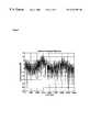
- FIG. 2illustrates the signal spectrum of White Noise after being reproduced by a loudspeaker housed in typical cabinet.
- FIG. 3depicts the filter structure proposed in the invention.
- FIG. 4illustrates the frequency response of an IIR filter of order 8 that models the cabinet characteristics.
- FIG. 5illustrates the frequency response of a FIR filter of order 64 that models the cabinet characteristics.
- FIG. 6illustrates the span of the FIR coefficient values.
- FIG. 7illustrates the FIR filter when used in conjunction with a IIR filter.
- FIG. 8is a block diagram showing the different hardware components of the Acoustic Echo Canceling System according to the present invention.
- FIG. 9illustrates the process of estimating the IIR fixed filter.
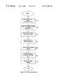
- FIG. 10is a flowchart depicting the sequence of processing steps performed by the digital signal processor estimating the fixed filter.
- FIG. 11depicts a filter structure proposed as an alternative embodiment of the invention.
- FIG. 3The preferred embodiment of an Echo Canceler structure used in this invention is depicted in FIG. 3 .
- the inventionseparates the echo path estimation process into 2 steps.
- the contribution of hardware componentsAnalog-to-digital and Digital to Analog converters 14 , 16
- the cabinet box(not shown), loudspeaker 18 , microphone 20 and the direct path coupling 24
- the indirect path through the environment 22is estimated using a FIR adaptive filter 12 b .
- the basic assumptionis that the first estimate is determined by the box structure and does not change in time. Therefore a fixed IIR filter 12 a can be used to model this path contribution.
- the indirect pathis time variable and therefore a FIR adaptive filter is used in the estimation process.
- FIG. 4shows the frequency response of a 64 tap FIR filter that otherwise would be necessary to obtain an accurate representation of the same spectral peaks in FIG. 4 .
- the IIR filter 12 acan be estimated at the production stage or at the initialization setup of the system and it will remain constant during operation of the hands free system.
- the adaptive filter 12 bonly needs to model the part of the echo path created by the environment. In this way the typical problem of time to initialize and adapt the adaptive filter coefficients can be reduced.
- the adaptive filter coefficientsconverge more rapidly to optimal values because they do not need to track fixed characteristics each time the filter is reset.
- FIG. 6shows the impulse response of the FIR filter in the single filter approach taken in the conventional approach as in the arrangement of FIG. 1, while FIG. 7 shows the FIR impulse response in case the invention is used and a fixed IIR filter is introduced in series before the FIR filter. As is apparent from FIG. 7, the impulse response of the fixed FIR filter reduces to a delta function representing only the delay between the receive channel (loudspeaker) and transmit channel (microphone).
- the fixed filter 12 ccan be used to modify the frequency response of the cabinet box (not shown) and its contents 18 20 according to specific characteristics.
- the frequency response of the direct echo path 24will be approximately flat and the adaptive filter 12 b only needs to track the echo delay between loudspeaker and microphone.
- the voice intelligibilitycan be improved by boosting the high portion of the spectrum. In this case the fixed filter 12 c should reflect the spectrum enhancement.
- the methodincludes two steps: first the fixed IIR filter 12 a is estimated and in the second the fixed filter is placed between the reference signal (loudspeaker) and the adaptive FIR filter in order to perform the echo cancellation.
- FIG. 8there is shown in accordance with the invention a block diagram showing the different components required in the implementation of the invention.
- the signal processing section 320includes a Digital Signal Processor 325 , a connection to a communication channel 330 that can be a regular analog telephone line or a digital PBX, program and data memory 335 , a Digital to Analog Converter 340 and an Analog-to-digital Converter 350 .
- the acoustic section 360includes a loudspeaker 370 , an acoustic cabinet 380 and a microphone 390 .
- the IIR filter estimationis performed as follows.
- the Digital Signal Processor 320internally generates a short pulse of white noise. This signal is converted to the analog domain by means of the Digital to Analog Converter 340 .
- the sampling frequency for this processis selected in such way that it is twice the maximum bandwidth of interest. For telephony application the bandwidth is 4 KHz. This is done according to the basic theory of sampling processes as is well known in the art.
- the loudspeaker 370reproduces the white noise signal.
- the Loudspeaker-cabinet combinationselectively affects the spectrum of the signal.
- the microphone 390senses this signal which is in term digitized by the Analog-to-digital converter 350 and fed into the Digital Signal Processor's memory.
- sections 320 , 360may be placed in an anechoic chamber. Alternatively, only a small number of samples taken before echoes from the environment reach the microphone may be used for the estimation.
- the Signal Processor 325processes the signal stored in memory in order to estimate the filter's coefficients that provide optimal representation of the spectral characteristics of the system.
- a TMS320C54 manufactured by Texas Instruments, Inc (Dallas, Tex.)can be used as a Digital Signal Processor.
- the Analog-to-digital and Digital to Analog Converterscan be found in a analog interface circuit as the TLC320AC02 also from Texas Instruments Inc. Any commercially available loudspeaker and microphone can be used as acoustics transducers.
- FIG. 9is a block diagram describing the different filters associated with the IIR estimation process described above.
- the transfer function representing the loudspeaker/microphone-cabinet and converter (A/D, D/A) combinationis represented by the filter 430 having the transfer function H s ( ⁇ )).
- the White noise generator 410 of Processor 325creates the input white noise signal w(t) 420 which is filtered by H s ( ⁇ ) 430 .
- a signal m(t) 440is obtained after the filtering process.
- the signal m(t) 440is picked up by the reference microphone and has a spectrum similar to the one depicted in FIG. 2 .
- FIG. 2an audio spectrum produced by a loudspeaker enclosed in a speakerphone box.
- a spectrum analyzerdisplays the frequency content of the signals sensed by the microphone, assuming that the loudspeaker and cabinet are located in an anechoic chamber and white noise is used as the sound source. If an ideal or perfect loudspeaker were used the spectrum analyzer would show the flat spectrum characteristic of white noise, but because of the selective nature of a real loudspeaker cabinet combination, the spectrum will show a series of resonant peaks.
- H se ( ⁇ )⁇ n 1 - A ⁇ ( ⁇ ) ( 1 )
- A( ⁇ )is a polynomial of order “p” and ⁇ n is the variance of the white noise.
- Such a modelcan be estimated using the Levinson-Durbin recursion. See “Linear Prediction: A tutorial review,” J. Makhoul, Proc. IEEE , Vol. 63, April 1975, pp. 561-580, which is incorporated herein in its entirety by reference. See especially section II entitled “Parameter Estimation” of this article beginning on page 126.
- the order of the modelis at least twice the number of peaks in the bandwidth of interest. Typical values for “p” are 8, 9 or 10.
- the polynomial coefficientsare the IIR filter coefficients.
- FIG. 10there is shown a flow chart illustrating the processing steps performed by the Digital Signal Processor to estimate the IIR filter coefficients.
- the processorgenerates random white noise via the Digital to Analog Converter interfaced to the Digital Signal Processor.
- the generated signalis reproduced by the loudspeaker and picked up by the reference microphone that is connected to the Analog-to-digital Converter.
- the microphone signalis acquired via the Analog-to-digital Converter that is interfaced to the Digital Signal Processor.
- the sampled signalis saved in the internal memory.
- the saved datais stored in step 530 in a buffer of 64 msec. At 8000 KHz sampling rate this represent 512 data points at 512 different consecutive sampling times 1 through 512.
- An analysis window in step 540multiplies the buffer.
- a Hamming windowaccording to the following equation is used:
- step 550An Autocorrelation analysis is applied in step 550 to the data points after the multiplication referred to above in connection to equation (2). Once the Autocorrelation coefficients are calculated the Levinson-Durbin recursion is computed in step 560 .
- the previous signal processing stepsare well known in the art and they are depicted in Makhoul, J a “Linear Prediction, a tutorial Review”, referenced above.
- the resulting autoregressive coefficientsare used to build the fixed filter at step 570 . This is done according to the following equation:
- S spk (n) and S ref (n)represent samples at sampling time “n” of the speaker and filtered signals respectively, and p the order of the IIR filter.
- S ref (n ⁇ 1), S ref ) n ⁇ 2), . . . S ref (n ⁇ p)represent samples at sampling times “n ⁇ 1”, “n ⁇ 2”, . . . , “n ⁇ p” of the filtered signals at the output of filter.
- the filter coefficientsare represented by the vector [1 a 1 a 2 , . . . , a p ].
- the difference equation 3represents an Infinite Impulse Response (IIR) filter as is well known in the field. (Theory and applications of Digital Signal Processing, by Rabiner and Gold, Chapter 4). Once the coefficients are calculated for a specific loudspeaker cabinet combination they remain in memory for the adaptive filtering process of eliminating the echo signals.
- IIRInfinite Impulse Response
- the adaptive echo canceleris implemented according with one of the well known adaptive algorithms like the Normalized LMS.
- the filteringis modified to accommodate the IIR filter before the FIR filter.
- the output of the fixed IIR filteris supplied as input to the adaptive FIR filter.
- NNumber of filter taps in the FIR filter
- S refFilter delay line, that is, sampled output of the filter 12 a in FIG. 3
- the main differencebeing that instead of having the speaker signal fed to the delay line of the FIR filter we have the IIR filtered signal Sref being fed to the FIR delay line.
- the output of the FIR filter ê(n)is the estimated echo. This estimate is subtracted from the real echo received via the microphone to obtain the error signal err(n) used in the adaptation process.
- err(n)Error signal given at the output of subtractor 30 by the difference between the output of the filter 12 b and the output of the analog to digital converter 16 in FIG. 3
- the valuesmay be stored in memory 335 in FIG. 8 for providing the estimated echo in Equation 4 above.
- this estimated echo ê(n)may then be subtracted from the output of the analog-to-digital converter 16 to cancel the echos along the direct path 24 as well as along the indirect path through environment 22 from the output of converter 16 .
- this cancellationmay be accomplished by means of a subtractor 30 .
- subtractor 30may also be implemented by means of software in processor 325 as well.
- these componentsmay also be implemented by other means such as Pentium processors from Intel® of Santa Clara, Calif. or through neural networks using non-processor based technology such as glue logic. Such and other implementations are within the scope of the invention.
- an inverse fixed filter 12 cmay be employed as shown in FIG. 11 where the output of filter 12 c is fed to the digital-to-analog converter 14 .
- frequencies of resonance of the cabinet 380 and its contents 370 , 390 and the filters 340 , 350 of FIG. 8can be estimated from the sound reproduced by the loud speaker 370 and picked up by the microphone 390 .
- the frequency response of the direct echo path 24 in FIG. 11will be approximately flat and the adaptive filter 12 b only needs to track the echo delay between the loud speaker and the microphone.
- This filterwill have spectral “valleys” where the cabinet and its contents have spectral “peaks” in such a way that the total system (Inverse filter+cabinet) has a flat frequency response.
- the output of filter 12 cis an estimate of an echo signal resulting from a system which has the inverse frequency response characteristics of the cabinet. When this estimated echo signal passes through the cabinet, the characteristics of the cabinet are removed from the signal, resulting in a speech signal reaching the microphone which is “free” of cabinet echo effects. Unlike the embodiment of FIG.
- filter 12 bprocesses either an output of a fixed filter (e.g. 12 a ) or a signal derived therefrom (e.g. derived by the cabinet from the output of filter 12 c ) to obtain a second output signal which is then used for cancelling echoes.
- the fixed filterderives an estimate related to echoes of the speech signal caused by the cabinet and its contents.
- the signals fed to the input of the loud speaker 18 and the signal fed to the input of the adaptive filter 12 bare different.
- the signal that is fed to loud speaker 18is first filtered by the fixed filter 12 a before it is applied to adaptive filter 12 b .
- the signal applied to adaptive filter 12 bis filtered first by fixed inverse filter 12 c before it is applied to loud speaker 18 .
- memory 399may be enclosed within the cabinet 380 as shown in FIG. 8 and the coefficients stored therein read by processor 325 , it is also possible to supply memory 399 in a form separate from the cabinet, such as in the form of a floppy disk or CD-ROM.
- the digital signal processor 325would read the coefficients from memory 399 along line 398 so that the coefficients of the fixed filter 12 a , 12 c need not be derived during the initialization of system 320 . This is particularly convenient for those in the mass market who purchase sections 360 , 320 separately and connect the two together. The digital signal processor would then only have to derive the coefficients of the adaptive filter 12 b as described above.
- the loud speaker and microphoneare shown within a cabinet in the figures described above, other arrangements are possible.
- the speakersmay be housed within cabinets for enhanced sound quality while the microphones may be located outside of the cabinet.
- This inventionmay be used for any arrangement of the loud speaker, microphone with or without a cabinet, and however the loud speaker and microphone are housed by means of a cabinet. All of the articles and references referred to above are incorporated herein in their entirety by reference.
Landscapes
- Engineering & Computer Science (AREA)
- Signal Processing (AREA)
- Computer Networks & Wireless Communication (AREA)
- Cable Transmission Systems, Equalization Of Radio And Reduction Of Echo (AREA)
- Circuit For Audible Band Transducer (AREA)
- Telephone Function (AREA)
Abstract
Description


Claims (36)
Priority Applications (1)
| Application Number | Priority Date | Filing Date | Title |
|---|---|---|---|
| US09/412,293US6744887B1 (en) | 1999-10-05 | 1999-10-05 | Acoustic echo processing system |
Applications Claiming Priority (1)
| Application Number | Priority Date | Filing Date | Title |
|---|---|---|---|
| US09/412,293US6744887B1 (en) | 1999-10-05 | 1999-10-05 | Acoustic echo processing system |
Publications (1)
| Publication Number | Publication Date |
|---|---|
| US6744887B1true US6744887B1 (en) | 2004-06-01 |
Family
ID=32326257
Family Applications (1)
| Application Number | Title | Priority Date | Filing Date |
|---|---|---|---|
| US09/412,293Expired - Fee RelatedUS6744887B1 (en) | 1999-10-05 | 1999-10-05 | Acoustic echo processing system |
Country Status (1)
| Country | Link |
|---|---|
| US (1) | US6744887B1 (en) |
Cited By (23)
| Publication number | Priority date | Publication date | Assignee | Title |
|---|---|---|---|---|
| US7003095B2 (en)* | 2000-09-29 | 2006-02-21 | Fujitsu Limited | Acoustic echo canceler and handsfree telephone set |
| US20060083389A1 (en)* | 2004-10-15 | 2006-04-20 | Oxford William V | Speakerphone self calibration and beam forming |
| US20060093128A1 (en)* | 2004-10-15 | 2006-05-04 | Oxford William V | Speakerphone |
| US20060132595A1 (en)* | 2004-10-15 | 2006-06-22 | Kenoyer Michael L | Speakerphone supporting video and audio features |
| US20060239443A1 (en)* | 2004-10-15 | 2006-10-26 | Oxford William V | Videoconferencing echo cancellers |
| US20060239477A1 (en)* | 2004-10-15 | 2006-10-26 | Oxford William V | Microphone orientation and size in a speakerphone |
| US20060256991A1 (en)* | 2005-04-29 | 2006-11-16 | Oxford William V | Microphone and speaker arrangement in speakerphone |
| US20060256974A1 (en)* | 2005-04-29 | 2006-11-16 | Oxford William V | Tracking talkers using virtual broadside scan and directed beams |
| US20060262942A1 (en)* | 2004-10-15 | 2006-11-23 | Oxford William V | Updating modeling information based on online data gathering |
| US20060262943A1 (en)* | 2005-04-29 | 2006-11-23 | Oxford William V | Forming beams with nulls directed at noise sources |
| US20060269074A1 (en)* | 2004-10-15 | 2006-11-30 | Oxford William V | Updating modeling information based on offline calibration experiments |
| US20060269080A1 (en)* | 2004-10-15 | 2006-11-30 | Lifesize Communications, Inc. | Hybrid beamforming |
| US20070019803A1 (en)* | 2003-05-27 | 2007-01-25 | Koninklijke Philips Electronics N.V. | Loudspeaker-microphone system with echo cancellation system and method for echo cancellation |
| US20070223713A1 (en)* | 2006-03-06 | 2007-09-27 | Gunness David W | Creating digital signal processing (DSP) filters to improve loudspeaker transient response |
| US20080031471A1 (en)* | 2006-05-19 | 2008-02-07 | Tim Haulick | System for equalizing an acoustic signal |
| US20090316923A1 (en)* | 2008-06-19 | 2009-12-24 | Microsoft Corporation | Multichannel acoustic echo reduction |
| US20100284529A1 (en)* | 2007-09-04 | 2010-11-11 | Oliver Brasse | Method and communication terminal for detecting the status of a telephone receiver |
| CN102263866A (en)* | 2010-05-25 | 2011-11-30 | 英特尔移动通信技术有限公司 | Audio communication device and method using fixed echo cancellation filter coefficients |
| US9800734B2 (en) | 2013-12-12 | 2017-10-24 | Koninklijke Philips N.V. | Echo cancellation |
| US9979505B2 (en) | 2012-09-10 | 2018-05-22 | Tellabs Enterprise, Inc. | Delivery of GPON technology |
| US10410653B2 (en) | 2015-03-27 | 2019-09-10 | Dolby Laboratories Licensing Corporation | Adaptive audio filtering |
| US10650839B2 (en)* | 2019-06-20 | 2020-05-12 | Intel Corporation | Infinite impulse response acoustic echo cancellation in the frequency domain |
| EP4030388A1 (en)* | 2017-04-21 | 2022-07-20 | Intel Corporation | Dedicated fixed point blending for energy efficiency |
Citations (12)
| Publication number | Priority date | Publication date | Assignee | Title |
|---|---|---|---|---|
| US4956838A (en)* | 1988-03-15 | 1990-09-11 | Etat Francais Represente Par Le Ministre Des Postes, Telecommunications Et De L'espace (Centre National D'etudes Des Telecommunications) | Echo cancelling device with frequency sub-band filtering |
| US5136577A (en) | 1990-02-21 | 1992-08-04 | Fujitsu Limited | Sub-band acoustic echo canceller |
| US5610909A (en) | 1995-05-31 | 1997-03-11 | Lucent Technologies Inc. | Multistage echo canceler including time variation compensation |
| US5631899A (en)* | 1995-05-31 | 1997-05-20 | Lucent Technologies Inc. | Acoustic echo canceler |
| US5818945A (en)* | 1995-04-20 | 1998-10-06 | Nippon Telegraph And Telephone | Subband echo cancellation method using projection algorithm |
| US5841856A (en)* | 1996-05-22 | 1998-11-24 | Nec Corporation | Hands-free telephone set |
| US6097971A (en)* | 1996-04-23 | 2000-08-01 | Nec Corporation | Hands-free speech communication apparatus |
| US6108412A (en)* | 1997-10-07 | 2000-08-22 | Nortel Networks Corporation | Adaptive echo cancelling system for telephony applications |
| US6181753B1 (en)* | 1997-04-30 | 2001-01-30 | Oki Electric Industry Co., Ltd. | Echo/noise canceler with delay compensation |
| US6181794B1 (en)* | 1997-03-07 | 2001-01-30 | Samsung Electronics Co., Ltd. | Echo canceler and method thereof |
| US6381569B1 (en)* | 1998-02-04 | 2002-04-30 | Qualcomm Incorporated | Noise-compensated speech recognition templates |
| US6505057B1 (en)* | 1998-01-23 | 2003-01-07 | Digisonix Llc | Integrated vehicle voice enhancement system and hands-free cellular telephone system |
- 1999
- 1999-10-05USUS09/412,293patent/US6744887B1/ennot_activeExpired - Fee Related
Patent Citations (12)
| Publication number | Priority date | Publication date | Assignee | Title |
|---|---|---|---|---|
| US4956838A (en)* | 1988-03-15 | 1990-09-11 | Etat Francais Represente Par Le Ministre Des Postes, Telecommunications Et De L'espace (Centre National D'etudes Des Telecommunications) | Echo cancelling device with frequency sub-band filtering |
| US5136577A (en) | 1990-02-21 | 1992-08-04 | Fujitsu Limited | Sub-band acoustic echo canceller |
| US5818945A (en)* | 1995-04-20 | 1998-10-06 | Nippon Telegraph And Telephone | Subband echo cancellation method using projection algorithm |
| US5610909A (en) | 1995-05-31 | 1997-03-11 | Lucent Technologies Inc. | Multistage echo canceler including time variation compensation |
| US5631899A (en)* | 1995-05-31 | 1997-05-20 | Lucent Technologies Inc. | Acoustic echo canceler |
| US6097971A (en)* | 1996-04-23 | 2000-08-01 | Nec Corporation | Hands-free speech communication apparatus |
| US5841856A (en)* | 1996-05-22 | 1998-11-24 | Nec Corporation | Hands-free telephone set |
| US6181794B1 (en)* | 1997-03-07 | 2001-01-30 | Samsung Electronics Co., Ltd. | Echo canceler and method thereof |
| US6181753B1 (en)* | 1997-04-30 | 2001-01-30 | Oki Electric Industry Co., Ltd. | Echo/noise canceler with delay compensation |
| US6108412A (en)* | 1997-10-07 | 2000-08-22 | Nortel Networks Corporation | Adaptive echo cancelling system for telephony applications |
| US6505057B1 (en)* | 1998-01-23 | 2003-01-07 | Digisonix Llc | Integrated vehicle voice enhancement system and hands-free cellular telephone system |
| US6381569B1 (en)* | 1998-02-04 | 2002-04-30 | Qualcomm Incorporated | Noise-compensated speech recognition templates |
Non-Patent Citations (3)
| Title |
|---|
| "Adaptive Echo Cancellation for Speech Signals," M.M. Sondhi et al., Advances in Speech Signal Processing, published by Marcel Dekker, Inc., 1992, Chapter 11, pp. 327-355. |
| "Linear Prediction: A Tutorial Review," J. Makhoul, pp, 124-143 (reprinted from Proceedings of the IEEE, vol. 63, Apr. 1975, pp. 561-580). |
| Patent Search conducted on Jul. 6, 1999, 38 pages. |
Cited By (45)
| Publication number | Priority date | Publication date | Assignee | Title |
|---|---|---|---|---|
| US7003095B2 (en)* | 2000-09-29 | 2006-02-21 | Fujitsu Limited | Acoustic echo canceler and handsfree telephone set |
| US20070019803A1 (en)* | 2003-05-27 | 2007-01-25 | Koninklijke Philips Electronics N.V. | Loudspeaker-microphone system with echo cancellation system and method for echo cancellation |
| US7903137B2 (en) | 2004-10-15 | 2011-03-08 | Lifesize Communications, Inc. | Videoconferencing echo cancellers |
| US20060083389A1 (en)* | 2004-10-15 | 2006-04-20 | Oxford William V | Speakerphone self calibration and beam forming |
| US20060239443A1 (en)* | 2004-10-15 | 2006-10-26 | Oxford William V | Videoconferencing echo cancellers |
| US20060239477A1 (en)* | 2004-10-15 | 2006-10-26 | Oxford William V | Microphone orientation and size in a speakerphone |
| US7970151B2 (en) | 2004-10-15 | 2011-06-28 | Lifesize Communications, Inc. | Hybrid beamforming |
| US20060132595A1 (en)* | 2004-10-15 | 2006-06-22 | Kenoyer Michael L | Speakerphone supporting video and audio features |
| US20060262942A1 (en)* | 2004-10-15 | 2006-11-23 | Oxford William V | Updating modeling information based on online data gathering |
| US7826624B2 (en) | 2004-10-15 | 2010-11-02 | Lifesize Communications, Inc. | Speakerphone self calibration and beam forming |
| US20060269074A1 (en)* | 2004-10-15 | 2006-11-30 | Oxford William V | Updating modeling information based on offline calibration experiments |
| US20060269080A1 (en)* | 2004-10-15 | 2006-11-30 | Lifesize Communications, Inc. | Hybrid beamforming |
| US20060093128A1 (en)* | 2004-10-15 | 2006-05-04 | Oxford William V | Speakerphone |
| US7760887B2 (en) | 2004-10-15 | 2010-07-20 | Lifesize Communications, Inc. | Updating modeling information based on online data gathering |
| US8116500B2 (en) | 2004-10-15 | 2012-02-14 | Lifesize Communications, Inc. | Microphone orientation and size in a speakerphone |
| US7720232B2 (en) | 2004-10-15 | 2010-05-18 | Lifesize Communications, Inc. | Speakerphone |
| US7720236B2 (en) | 2004-10-15 | 2010-05-18 | Lifesize Communications, Inc. | Updating modeling information based on offline calibration experiments |
| US7991167B2 (en) | 2005-04-29 | 2011-08-02 | Lifesize Communications, Inc. | Forming beams with nulls directed at noise sources |
| US7593539B2 (en) | 2005-04-29 | 2009-09-22 | Lifesize Communications, Inc. | Microphone and speaker arrangement in speakerphone |
| US7907745B2 (en) | 2005-04-29 | 2011-03-15 | Lifesize Communications, Inc. | Speakerphone including a plurality of microphones mounted by microphone supports |
| US20060262943A1 (en)* | 2005-04-29 | 2006-11-23 | Oxford William V | Forming beams with nulls directed at noise sources |
| US7970150B2 (en) | 2005-04-29 | 2011-06-28 | Lifesize Communications, Inc. | Tracking talkers using virtual broadside scan and directed beams |
| US20060256974A1 (en)* | 2005-04-29 | 2006-11-16 | Oxford William V | Tracking talkers using virtual broadside scan and directed beams |
| US20060256991A1 (en)* | 2005-04-29 | 2006-11-16 | Oxford William V | Microphone and speaker arrangement in speakerphone |
| US20070223713A1 (en)* | 2006-03-06 | 2007-09-27 | Gunness David W | Creating digital signal processing (DSP) filters to improve loudspeaker transient response |
| US8081766B2 (en) | 2006-03-06 | 2011-12-20 | Loud Technologies Inc. | Creating digital signal processing (DSP) filters to improve loudspeaker transient response |
| US8098848B2 (en)* | 2006-05-19 | 2012-01-17 | Nuance Communications, Inc. | System for equalizing an acoustic signal |
| US20080031471A1 (en)* | 2006-05-19 | 2008-02-07 | Tim Haulick | System for equalizing an acoustic signal |
| US20100284529A1 (en)* | 2007-09-04 | 2010-11-11 | Oliver Brasse | Method and communication terminal for detecting the status of a telephone receiver |
| US8335309B2 (en)* | 2007-09-04 | 2012-12-18 | Siemens Enterprise Communications Gmbh & Co. Kg | Method and communication terminal for detecting the status of a telephone receiver |
| US20130129101A1 (en)* | 2008-06-19 | 2013-05-23 | Microsoft Corporation | Multichannel acoustic echo reduction |
| US20090316923A1 (en)* | 2008-06-19 | 2009-12-24 | Microsoft Corporation | Multichannel acoustic echo reduction |
| US9264807B2 (en)* | 2008-06-19 | 2016-02-16 | Microsoft Technology Licensing, Llc | Multichannel acoustic echo reduction |
| US8385557B2 (en)* | 2008-06-19 | 2013-02-26 | Microsoft Corporation | Multichannel acoustic echo reduction |
| US9185233B2 (en)* | 2010-05-25 | 2015-11-10 | Intel Deutschland Gmbh | Audio communication device and method using fixed echo cancellation filter coefficients |
| US20110293104A1 (en)* | 2010-05-25 | 2011-12-01 | Infineon Technologies North America Corp. | Audio communication device and method using fixed echo cancellation filter coefficients |
| CN102263866A (en)* | 2010-05-25 | 2011-11-30 | 英特尔移动通信技术有限公司 | Audio communication device and method using fixed echo cancellation filter coefficients |
| CN102263866B (en)* | 2010-05-25 | 2016-08-31 | 英特尔移动通信有限责任公司 | Fixed echo is used to eliminate method and the VOCA voice communications assembly of filter coefficient |
| US9979505B2 (en) | 2012-09-10 | 2018-05-22 | Tellabs Enterprise, Inc. | Delivery of GPON technology |
| US11750315B2 (en) | 2012-09-10 | 2023-09-05 | Tellabs Bedford, Inc. | Delivery of GPON technology |
| US9800734B2 (en) | 2013-12-12 | 2017-10-24 | Koninklijke Philips N.V. | Echo cancellation |
| US10410653B2 (en) | 2015-03-27 | 2019-09-10 | Dolby Laboratories Licensing Corporation | Adaptive audio filtering |
| US11264045B2 (en) | 2015-03-27 | 2022-03-01 | Dolby Laboratories Licensing Corporation | Adaptive audio filtering |
| EP4030388A1 (en)* | 2017-04-21 | 2022-07-20 | Intel Corporation | Dedicated fixed point blending for energy efficiency |
| US10650839B2 (en)* | 2019-06-20 | 2020-05-12 | Intel Corporation | Infinite impulse response acoustic echo cancellation in the frequency domain |
Similar Documents
| Publication | Publication Date | Title |
|---|---|---|
| US6744887B1 (en) | Acoustic echo processing system | |
| US11297178B2 (en) | Method, apparatus, and computer-readable media utilizing residual echo estimate information to derive secondary echo reduction parameters | |
| US6246760B1 (en) | Subband echo cancellation method for multichannel audio teleconference and echo canceller using the same | |
| CN100477704C (en) | Method and apparatus for echo cancellation combined with adaptive beamforming | |
| US9992572B2 (en) | Dereverberation system for use in a signal processing apparatus | |
| US7062040B2 (en) | Suppression of echo signals and the like | |
| US8712068B2 (en) | Acoustic echo cancellation | |
| JP4954334B2 (en) | Apparatus and method for calculating filter coefficients for echo suppression | |
| EP1169883B1 (en) | System and method for dual microphone signal noise reduction using spectral subtraction | |
| US20040018860A1 (en) | Acoustic echo suppressor for hands-free speech communication | |
| EP1022866A1 (en) | Echo elimination method, echo canceler and voice switch | |
| CA2157708A1 (en) | Adaptive finite impulse response filtering method and apparatus | |
| US20070036344A1 (en) | Method and system for eliminating noises and echo in voice signals | |
| JP2012501152A (en) | Method for determining updated filter coefficients of an adaptive filter adapted by an LMS algorithm with pre-whitening | |
| JP3420705B2 (en) | Echo suppression method and apparatus, and computer-readable storage medium storing echo suppression program | |
| CN111213359A (en) | Echo canceller and method for echo canceller | |
| US7062039B1 (en) | Methods and apparatus for improving adaptive filter performance by inclusion of inaudible information | |
| JP3787088B2 (en) | Acoustic echo cancellation method, apparatus, and acoustic echo cancellation program | |
| US6954530B2 (en) | Echo cancellation filter | |
| EP1465159A1 (en) | Virtual microphone array | |
| Van Compernolle | DSP techniques for speech enhancement | |
| US20050175129A1 (en) | Echo canceller with model mismatch compensation | |
| JP3756828B2 (en) | Reverberation elimination method, apparatus for implementing this method, program, and recording medium therefor | |
| JP2002223182A (en) | Echo canceling method, its apparatus, its program and its recording medium | |
| JP3403549B2 (en) | Echo canceller |
Legal Events
| Date | Code | Title | Description |
|---|---|---|---|
| AS | Assignment | Owner name:VPACKET.COM INC., A CORP. OF CALIFORNIA, CALIFORNI Free format text:ASSIGNMENT OF ASSIGNORS INTEREST;ASSIGNORS:BERSTEIN, ALBERTO D.;WEI, ABRAHAM;WEI, TOM;REEL/FRAME:010301/0929 Effective date:19991001 | |
| AS | Assignment | Owner name:FRONTIER TECHNOLOGY DEVELOPMENT LIMITED, HONG KONG Free format text:ASSIGNMENT OF ASSIGNORS INTEREST;ASSIGNOR:VPACKET COMMUNICATIONS, INC.;REEL/FRAME:011554/0208 Effective date:20010212 | |
| AS | Assignment | Owner name:ZHONE TECHNOLOGIES, INC., CALIFORNIA Free format text:ASSIGNMENT OF ASSIGNORS INTEREST;ASSIGNOR:FRONTIER TECHNOLOGY DEVELOPMENT LIMITED;REEL/FRAME:019035/0722 Effective date:20070320 | |
| AS | Assignment | Owner name:SUMMIT TECHNOLOGY SYSTEMS, LP, PENNSYLVANIA Free format text:ASSIGNMENT OF ASSIGNORS INTEREST;ASSIGNORS:ZHONE TECHNOLOGIES, INC.;PARADYNE CORPORATION;REEL/FRAME:019649/0818 Effective date:20070702 Owner name:SUMMIT TECHNOLOGY SYSTEMS, LP,PENNSYLVANIA Free format text:ASSIGNMENT OF ASSIGNORS INTEREST;ASSIGNORS:ZHONE TECHNOLOGIES, INC.;PARADYNE CORPORATION;REEL/FRAME:019649/0818 Effective date:20070702 | |
| FEPP | Fee payment procedure | Free format text:PAYOR NUMBER ASSIGNED (ORIGINAL EVENT CODE: ASPN); ENTITY STATUS OF PATENT OWNER: LARGE ENTITY Free format text:PAYER NUMBER DE-ASSIGNED (ORIGINAL EVENT CODE: RMPN); ENTITY STATUS OF PATENT OWNER: LARGE ENTITY | |
| FPAY | Fee payment | Year of fee payment:4 | |
| REMI | Maintenance fee reminder mailed | ||
| LAPS | Lapse for failure to pay maintenance fees | ||
| STCH | Information on status: patent discontinuation | Free format text:PATENT EXPIRED DUE TO NONPAYMENT OF MAINTENANCE FEES UNDER 37 CFR 1.362 | |
| FP | Lapsed due to failure to pay maintenance fee | Effective date:20120601 |