US6744009B1 - Combined laser-scribing and laser-breaking for shaping of brittle substrates - Google Patents
Combined laser-scribing and laser-breaking for shaping of brittle substratesDownload PDFInfo
- Publication number
- US6744009B1 US6744009B1US10/227,751US22775102AUS6744009B1US 6744009 B1US6744009 B1US 6744009B1US 22775102 AUS22775102 AUS 22775102AUS 6744009 B1US6744009 B1US 6744009B1
- Authority
- US
- United States
- Prior art keywords
- laser
- scribing
- sheet
- breaking
- combined
- Prior art date
- Legal status (The legal status is an assumption and is not a legal conclusion. Google has not performed a legal analysis and makes no representation as to the accuracy of the status listed.)
- Expired - Lifetime
Links
Images


Classifications
- B—PERFORMING OPERATIONS; TRANSPORTING
- B23—MACHINE TOOLS; METAL-WORKING NOT OTHERWISE PROVIDED FOR
- B23K—SOLDERING OR UNSOLDERING; WELDING; CLADDING OR PLATING BY SOLDERING OR WELDING; CUTTING BY APPLYING HEAT LOCALLY, e.g. FLAME CUTTING; WORKING BY LASER BEAM
- B23K26/00—Working by laser beam, e.g. welding, cutting or boring
- B23K26/14—Working by laser beam, e.g. welding, cutting or boring using a fluid stream, e.g. a jet of gas, in conjunction with the laser beam; Nozzles therefor
- B23K26/146—Working by laser beam, e.g. welding, cutting or boring using a fluid stream, e.g. a jet of gas, in conjunction with the laser beam; Nozzles therefor the fluid stream containing a liquid
- B—PERFORMING OPERATIONS; TRANSPORTING
- B23—MACHINE TOOLS; METAL-WORKING NOT OTHERWISE PROVIDED FOR
- B23K—SOLDERING OR UNSOLDERING; WELDING; CLADDING OR PLATING BY SOLDERING OR WELDING; CUTTING BY APPLYING HEAT LOCALLY, e.g. FLAME CUTTING; WORKING BY LASER BEAM
- B23K26/00—Working by laser beam, e.g. welding, cutting or boring
- B23K26/36—Removing material
- B23K26/40—Removing material taking account of the properties of the material involved
- B—PERFORMING OPERATIONS; TRANSPORTING
- B23—MACHINE TOOLS; METAL-WORKING NOT OTHERWISE PROVIDED FOR
- B23K—SOLDERING OR UNSOLDERING; WELDING; CLADDING OR PLATING BY SOLDERING OR WELDING; CUTTING BY APPLYING HEAT LOCALLY, e.g. FLAME CUTTING; WORKING BY LASER BEAM
- B23K26/00—Working by laser beam, e.g. welding, cutting or boring
- B23K26/50—Working by transmitting the laser beam through or within the workpiece
- B23K26/53—Working by transmitting the laser beam through or within the workpiece for modifying or reforming the material inside the workpiece, e.g. for producing break initiation cracks
- B—PERFORMING OPERATIONS; TRANSPORTING
- B28—WORKING CEMENT, CLAY, OR STONE
- B28D—WORKING STONE OR STONE-LIKE MATERIALS
- B28D1/00—Working stone or stone-like materials, e.g. brick, concrete or glass, not provided for elsewhere; Machines, devices, tools therefor
- B28D1/22—Working stone or stone-like materials, e.g. brick, concrete or glass, not provided for elsewhere; Machines, devices, tools therefor by cutting, e.g. incising
- B28D1/221—Working stone or stone-like materials, e.g. brick, concrete or glass, not provided for elsewhere; Machines, devices, tools therefor by cutting, e.g. incising by thermic methods
- B—PERFORMING OPERATIONS; TRANSPORTING
- B28—WORKING CEMENT, CLAY, OR STONE
- B28D—WORKING STONE OR STONE-LIKE MATERIALS
- B28D5/00—Fine working of gems, jewels, crystals, e.g. of semiconductor material; apparatus or devices therefor
- B28D5/0005—Fine working of gems, jewels, crystals, e.g. of semiconductor material; apparatus or devices therefor by breaking, e.g. dicing
- B28D5/0011—Fine working of gems, jewels, crystals, e.g. of semiconductor material; apparatus or devices therefor by breaking, e.g. dicing with preliminary treatment, e.g. weakening by scoring
- C—CHEMISTRY; METALLURGY
- C03—GLASS; MINERAL OR SLAG WOOL
- C03B—MANUFACTURE, SHAPING, OR SUPPLEMENTARY PROCESSES
- C03B33/00—Severing cooled glass
- C03B33/02—Cutting or splitting sheet glass or ribbons; Apparatus or machines therefor
- C03B33/04—Cutting or splitting in curves, especially for making spectacle lenses
- C—CHEMISTRY; METALLURGY
- C03—GLASS; MINERAL OR SLAG WOOL
- C03B—MANUFACTURE, SHAPING, OR SUPPLEMENTARY PROCESSES
- C03B33/00—Severing cooled glass
- C03B33/09—Severing cooled glass by thermal shock
- C03B33/091—Severing cooled glass by thermal shock using at least one focussed radiation beam, e.g. laser beam
- C03B33/093—Severing cooled glass by thermal shock using at least one focussed radiation beam, e.g. laser beam using two or more focussed radiation beams
- B—PERFORMING OPERATIONS; TRANSPORTING
- B23—MACHINE TOOLS; METAL-WORKING NOT OTHERWISE PROVIDED FOR
- B23K—SOLDERING OR UNSOLDERING; WELDING; CLADDING OR PLATING BY SOLDERING OR WELDING; CUTTING BY APPLYING HEAT LOCALLY, e.g. FLAME CUTTING; WORKING BY LASER BEAM
- B23K2103/00—Materials to be soldered, welded or cut
- B23K2103/50—Inorganic material, e.g. metals, not provided for in B23K2103/02 – B23K2103/26
- Y—GENERAL TAGGING OF NEW TECHNOLOGICAL DEVELOPMENTS; GENERAL TAGGING OF CROSS-SECTIONAL TECHNOLOGIES SPANNING OVER SEVERAL SECTIONS OF THE IPC; TECHNICAL SUBJECTS COVERED BY FORMER USPC CROSS-REFERENCE ART COLLECTIONS [XRACs] AND DIGESTS
- Y02—TECHNOLOGIES OR APPLICATIONS FOR MITIGATION OR ADAPTATION AGAINST CLIMATE CHANGE
- Y02P—CLIMATE CHANGE MITIGATION TECHNOLOGIES IN THE PRODUCTION OR PROCESSING OF GOODS
- Y02P40/00—Technologies relating to the processing of minerals
- Y02P40/50—Glass production, e.g. reusing waste heat during processing or shaping
- Y02P40/57—Improving the yield, e-g- reduction of reject rates
Definitions
- the present inventionrelates to a method for cutting sheets of brittle materials into desired configurations or shapes utilizing a combined laser-scribing and laser-breaking technique.
- the present inventionhas particular applicability in cutting or separating brittle, non-magnetic sheets along curvilinear paths to produce substrates for use in the manufacture of magnetic and/or magneto-optical (MO) recording media.
- MOmagneto-optical
- Two techniquesare conventionally employed for cutting or shaping a sheet of brittle material, such as a glass, amorphous glass, glass-ceramic or ceramic material, to form a sheet or substrate with a desired configuration or geometry.
- a first such conventional methodinvolves mechanical scribing of the sheet employing a hard device, such as a diamond tip, to score the surface of the brittle material, which is then broken along the score line or pattern.
- the second of such conventional techniquesinvolves laser-scribing.
- Such laser-scribingtypically utilizes a continuous wave (“CW”) laser, such as a CO 2 laser of 10.6 ⁇ m wavelength, to heat a localized zone of a brittle material, such as an amorphous-glass sheet (similar to float glass), up to a temperature below the softening point of the material, and then immediately quenching the heated zone by applying a fluid coolant, e.g., a gas, such as air, a liquid, such as water, or a combination of a gas and a liquid, such as air/water.
- CWcontinuous wave
- CO 2 laserof 10.6 ⁇ m wavelength
- the output beam of a 10.6 ⁇ m CW CO 2 laser, or a high frequency pulse repetition rate 10.6 ⁇ m CO 2 laseris re-shaped into a beam with an elongated spot shape, which beam is utilized in an unfocussed manner for locally heating the glass.
- the locally heated zoneis then chilled by spraying thereon cool air or an air/liquid (e.g., air/water) mixture.
- the defect or micro-crackWhen the localized heating/cooling process starts from a small surface defect or micro-crack made in the glass, e.g., by a means of a mechanical scriber or indenter, or by application of suitable laser pulses, the defect or micro-crack propagates to form a scribing line due to the combination of localized heating-quenching which initiates tiny surface cracks arising from compression-tension stress effects.
- the sheet of materialis then separated, i.e., broken, along the scribing line by applying an external thermal or mechanical stress.
- a conventional laser-scribing technique utilizing a low power CO 2 laseris disclosed by Kondratenko in U.S. Pat. No. 5,609,284, wherein an elliptical target area is impinged with a beam of coherent radiation along the intended direction of the crack, while a stream of fluid coolant is directed at a point on the heated surface on the intended line of the crack.
- U.S. Pat. No. 6,259,058 B1 to Hoekstradiscloses a modification of U.S. Pat. No. 5,609,284 wherein dual laser beams are utilized after cooling in order to assist separation along the laser-scribing line. Allaire et al. in U.S. Pat. No. 5,776,220 disclose a laser-scribing technique for brittle materials wherein the laser spot has an extremely elongated elliptical shape such that its major axis is greater than 20 mm to enable rapid scribing.
- annular disk-shaped substrates suitable for use in magnetic and/or magneto-optical (MO) recording mediainclude various brittle materials, such as glasses, ceramics and glass-ceramics.
- two circular scribingsmust be performed with high precision, one defining the outer diameter (e.g., ranging from about 65 to about 95 mm, such as 84 mm) and one defining the inner diameter (e.g., ranging from about 20 to about 25 mm).
- Another drawback/disadvantage of conventional laser-scribing technologyis associated with the methodology for separating/breaking the brittle substrate (e.g., of amorphous glass) subsequent to laser-scribing. Specifically, because of the nature of the localized heating/cooling of the laser-scribing process, and due to the formation of a compression layer on the surface of the amorphous glass sheet, the propagation of micro-cracks during the laser-scribing process occurs in the layer nearest the glass surface.
- the scribe line provided by a single laser beam at the surface of a glass surfaceis insufficiently deep, and application of additional mechanical force to the glass sheet is typically required during the laser-scribing process or subsequent thereto, disadvantageously resulting in edge defects, residual stresses, increased risk of cracking resulting in product loss (i.e., low yield), reduced product throughput, and poor cost-effectiveness arising from a requirement for complicated, thus expensive, processing.
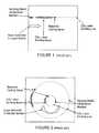
- FIG. 2illustrates an example of a similar, curvilinear laser-scribing process performed on a square or rectangular glass sheet for shaping the latter into an annular disk-shaped substrate, e.g., for use in the manufacture of disk-shaped, thin film magnetic and/or magneto-optical (MO) recording media.
- MOmagneto-optical
- the sheetis preliminarily provided with defect initialization markers (again indicated by dark circles in the drawing) arranged in a pair of concentric circles having diameters generally corresponding to the desired inner diameter (ID) and outer diameter (OD) of the medium, and proportionately-sized, arcuately extending, elliptically-shaped, stationary CO 2 laser-scribing beams, along with a stationary H 2 O/air cooling spray, are utilized for scribing each of the inner and outer diameters along the corresponding circular lines of defect initialization markers while the sheet is rotated about a central axis to effect relative movement between the sheet and each of the laser-scribing beam +H 2 O/air spray combinations.
- defect initialization markers(again indicated by dark circles in the drawing) arranged in a pair of concentric circles having diameters generally corresponding to the desired inner diameter (ID) and outer diameter (OD) of the medium, and proportionately-sized, arcuately extending, elliptically-shaped, stationary CO 2 laser-scrib
- step 4)is typically required to effect separation along the scribing line, in which step a portion of the sheet on one side of the scribing line is heated, while another portion of the sheet on the opposite side of the scribing line is chilled, causing the scribing line to propagate across substantially the entire thickness of the sheet, thereby facilitating separation.
- a pair of laser beamsmay be utilized for scribing the upper and lower surfaces, respectively, as illustrated in FIG. 5 .
- removal of the center portion of the sheete.g., by post-scribing thermal treatment
- for forming the ID of the diskis facilitated by presence of the offset alignment of the laser-scribing lines on opposite sides of the sheet.
- the post-scribing thermal-breaking stepis slow, complicated, and of inconsistent quality, leading to product loss (i.e., reduced yield) and additional expense, ultimately resulting in poor cost-effectiveness.
- the heating/chilling aspect of the processis difficult to perform with thicker glass sheets.
- a laser-based process and apparatuswhich is especially well-adapted for performing combined scribing and post-scribing separation/shaping of brittle substrates, such as glass sheets, into a desired shape/contour, e.g., into annular-shaped disks with inner and outer diameters for use in the manufacture of magnetic and/or MO recording media, which methodology and apparatus provide a simple, readily controllable manufacturing process with increased product throughput and cost-effectiveness.
- An advantage of the present inventionis an improved method of shaping a sheet of brittle material by segmenting.
- Another advantage of the present inventionis an improved method of separating a sheet of a brittle material into portions by means of combined laser-scribing + laser-breaking.
- Yet another advantage of the present inventionis an improved method of shaping a sheet of brittle material along concentric inner and outer circular paths to form an annular disk.
- a further advantage of the present inventionis an improved apparatus for shaping a sheet of brittle material by segmenting.
- a still further advantage of the present inventionis an improved apparatus for separating a sheet of a brittle material into portions by means of combined laser-scribing + laser-shaping.
- a yet further advantage of the present inventionis an improved apparatus for shaping a sheet of brittle material along concentric inner and outer circular paths to form an annular disk.
- segmenting the sheet along the thus-formed combined laser scribing + laser-breaking linewherein the first laser-based process to form the laser-scribing line comprises sequential steps of:
- the methodcomprises steps of:
- a first source of laser radiationadapted for irradiating selected portions of the first surface of the sheet of brittle material with a first wavelength laser beam for forming the laser-scribing line therein to the first depth below the first surface;
- a second source of laser radiationadapted for irradiating the selected portions of the first surface of the sheet of brittle material with a second wavelength laser beam for forming therein the laser-breaking line extending from the laser-scribing line at the first depth below the first surface to the second, greater depth below the first surface; the apparatus further comprising:
- step (a)comprises providing a sheet of brittle material including a plurality of defect initialization markers formed in the first surface thereof, the plurality of defect initialization markers extending along at least one line corresponding to the predetermined path of the at least one combined laser-scribing + laser-breaking line formed in step (c), and according to embodiments of the present invention, the plurality of defect initialization markers are formed in the first surface of the sheet by mechanical scribing, mechanical indentation, or pulsed-laser treatment.
- step (a)comprises providing a sheet of a brittle material selected from the group consisting of glass, amorphous glass, ceramics, and glass-ceramics;
- step (b)comprises providing an apparatus wherein the first wavelength laser beam from the first source (i) is of a longer wavelength than the second wavelength laser beam from the second source (iii), e.g., step (b) comprises providing an apparatus wherein the first source (i) of laser radiation is a CW CO 2 laser providing a first laser beam having a cross-sectional shape in the form of a first elongated ellipse, and the second source (iii) of laser radiation is a pulsed UV laser providing a second laser beam having a cross-sectional shape in the form of a second elongated ellipse, the first ellipse having a greater length than the second ellipse.
- the first source (i) of laser radiationis a CW CO 2 laser providing a first laser beam having a cross-sectional
- step (b))comprises providing an apparatus wherein the source of fluid coolant (ii) is a source of H 2 O/air, and further comprises providing an apparatus wherein the means (iv) for effecting relative movement between the first surface of the sheet and the at least one combined laser-scribing/laser-breaking assembly comprises means for moving the sheet while maintaining the at least one combined laser-scribing laser-breaking assembly stationary, thereby to form the at least one combined laser-scribing + laser-breaking line extending along a said predetermined path.
- the source of fluid coolant (ii)is a source of H 2 O/air
- the means (iv) for effecting relative movement between the first surface of the sheet and the at least one combined laser-scribing/laser-breaking assemblycomprises means for moving the sheet while maintaining the at least one combined laser-scribing laser-breaking assembly stationary, thereby to form the at least one combined laser-scribing + laser-breaking line extending along a said predetermined path.
- step (c)comprises moving the first surface of the sheet to form therein at least one combined laser-scribing + laser-breaking line extending along at least one predetermined linear, curvilinear, or linear-curvilinear path; and according to certain preferred embodiments of the present invention, step (c) comprises rotating the first surface of the sheet about a central axis to form therein at least one combined laser-scribing + laser-breaking line extending along at least one predetermined circular path.
- step (b)comprises providing an apparatus comprising a pair of radially spaced-apart, combined laser-scribing/laser-breaking assemblies each arranged in an arc around a central axis;
- step (c)comprises moving the first surface of the sheet about the central axis while maintaining each of the pair of combined laser/scribing/laser-breaking assemblies stationary to form therein a concentric pair of combined laser-scribing + laser-breaking lines extending along a pair of predetermined circular paths; and
- step (d)comprises segmenting the sheet along each of the concentric pair of combined laser-scribing + laser-breaking lines to form an annular disk-shaped substrate.
- step (b)comprises providing an apparatus comprising another first source of laser radiation (i) adapted for irradiating selected portions of the second surface of the sheet of brittle material with the first wavelength laser beam for forming a laser-scribing line therein in substantial vertical registry with the combined laser-scribing + laser-breaking line.
- Another aspect of the present inventionis an apparatus for performing combined laser-scribing and laser-breaking of a sheet of a brittle material, comprising:
- a first source of laser radiationadapted for irradiating selected portions of a first surface of the sheet of brittle material with a first wavelength laser beam for forming a laser-scribing line therein extending from the first surface to a first depth below the first surface;
- a second source of laser radiationadapted for irradiating the selected portions of the first surface of the sheet with a second wavelength laser beam for forming therein a laser-breaking line extending from the first depth below the first surface to a second, greater depth below the first surface to thereby form a combined laser-scribing + laser-breaking line;
- the at least one combined laser-scribing/laser-breaking assembly(a) comprises: a first source (i) of laser radiation in the form of a CW CO 2 laser providing a first laser beam having a cross-sectional shape of a first elongated ellipse; a source of H 2 O/air as the source of fluid coolant (ii); and a second source (iii) of laser radiation in the form of a pulsed UV laser providing a second laser beam of shorter wavelength than the first laser beam and having a cross-sectional shape in the form of a second elongated ellipse, the first ellipse having a greater length than the second ellipse;
- the means (b) for effecting relative movement between the first surface of the sheet and the at least one combined laser-scribing/laser-breaking assemblycomprises means for moving the sheet while maintaining the at least one combined laser-scribing/laser-breaking assembly stationary, thereby to form the
- the apparatuscomprises a pair of radially spaced-apart, combined laser-scribing/laser-breaking assemblies (a) each arranged in an arc around a central axis; and means (b) for effecting relative movement between the first surface of the sheet and the pair of combined laser-scribing/laser-breaking assemblies comprises means for rotating the sheet around the central axis while maintaining the pair of combined laser-scribing/laser-breaking assemblies stationary, to form in the sheet a concentric pair of combined laser-scribing + laser-breaking lines extending along a pair of predetermined circular paths.
- the apparatusfurther comprises at least one additional first source of laser radiation (i) adapted for irradiating selected portions of a second, oppositely facing surface of the sheet of brittle material with a first wavelength laser beam for forming at least one laser-scribing line therein in substantial vertical registry with a the at least one combined laser-scribing + laser-breaking line formed by the at least one combined laser-scribing/laser-breaking assembly.
- at least one additional first source of laser radiationi) adapted for irradiating selected portions of a second, oppositely facing surface of the sheet of brittle material with a first wavelength laser beam for forming at least one laser-scribing line therein in substantial vertical registry with a the at least one combined laser-scribing + laser-breaking line formed by the at least one combined laser-scribing/laser-breaking assembly.
- Yet another aspect of the present inventionis an apparatus for performing combined laser-scribing and laser-breaking of a sheet of a brittle material, comprising:
- (b)means for moving the sheet of brittle material relative to means (a) to form therein at least one combined laser-scribing + laser-breaking line extending along a predetermined path.
- FIGS. 1-2are simplified, schematic plan views for illustrating conventional linear and circular CO 2 laser-scribing, respectively, of glass sheets;
- FIG. 3is a simplified, schematic cross-sectional view for illustrating conventional, single-stage CO 2 laser-scribing of a single surface of a glass sheet;
- FIG. 4is a simplified, schematic cross-sectional view for illustrating conventional, two-stage CO 2 laser-scribing of a single surface of a glass sheet;
- FIG. 5is a simplified, schematic cross-sectional view for illustrating conventional, single-stage CO 2 laser-scribing of both surfaces of a glass sheet with adjustable offset of the top and bottom laser scribings;
- FIG. 6is a simplified, schematic cross-sectional view for illustrating conventional, two-stage CO 2 laser-scribing of both surfaces of a glass sheet with adjustable offset of the top and bottom laser scribings;
- FIGS. 7-8are simplified, schematic plan views for illustrating apparatus and method for performing linear and circular, single-stage combined laser-scribing + laser-breaking, respectively, of glass sheets according to embodiments of the present invention
- FIG. 9is a simplified, schematic cross-sectional view for illustrating the principle of single-stage combined laser-scribing + laser-breaking of glass sheets according to embodiments of the present invention.
- FIG. 10is a simplified, schematic cross-sectional view for illustrating apparatus, method, and the principle of single-stage combined laser-scribing + laser-breaking of glass sheets with an additional laser-scribing stage, according to embodiments of the present invention.
- the present inventionis based upon the discovery by the inventors that reliable and well-controlled linear and/or curvilinear separation/segmentation of sheets of brittle, non-metallic materials, such as of glass, can be accomplished in cost-effective manner by means of simplified methodology and apparatus for performing combined laser-scribing and post-scribing laser-breaking of brittle sheets at higher product throughput rates and yields (i.e., reduced product loss rates) than attainable with conventional CO 2 laser-based scribing technology.
- a first laser sourcee.g., a CW CO 2 laser Operating at a wavelength of 10.6 ⁇ m, and a fluid coolant source, is utilized for performing laser-scribing of a continuously moving sheet of brittle material to form a scribing line originating from a previously formed defect (initiator) in the surface of the sheet and extending downwardly to a first, relatively shallow depth below the surface, which laser-scribing process is immediately followed by a laser-breaking process utilizing a second, shorter wavelength laser source, e.g., a UV laser operating at a wavelength of 355 nm, for forming a micro-crack-containing breaking zone extending downwardly into the sheet from the first, relatively shallow depth of the laser-scribed line to a second, relatively deep depth.
- a second, shorter wavelength laser sourcee.g., a UV laser operating at a wavelength of 355 nm
- Separation, i.e., segmentation, of the sheet along the resultant combined laser-scribing + laser-breaking lineis then readily accomplished to yield high edge quality at high throughput rates at high product yield.
- inventive methodologyis equally applicable to separation/segmentation of brittle substrates along linear, curvilinear, or linear-curvilinear combined laser-scribing + laser-breaking lines.
- the inventionthus provides a CO 2 + UV laser-based solution to the problem of performing accurate and cost-effective separation of sheets of glass and other brittle, non-metallic materials along curvilinear paths, particularly as required in the manufacture of annular disk-shaped substrates for magnetic and/or magneto-optical (MO) recording media requiring formation of a circularly-shaped outer periphery (i.e., outer diameter, OD) and a circularly-shaped inner hole (i.e., inner diameter, ID).
- a circularly-shaped outer peripheryi.e., outer diameter, OD
- inner holei.e., inner diameter, ID
- FIG. 7illustrated therein is a simplified, schematic plan views for illustrating apparatus and method for performing linear, single-stage combined laser-scribing + laser-breaking, respectively, of glass sheets according to an embodiment of the present invention, wherein a surface (e.g., the upper surface) of a generally square or rectangularly-shaped sheet of a brittle material, illustratively of glass, is initially provided, as by a mechanical scribing or indentation process, or by a laser pulsing process, with a plurality of closely-spaced defect initialization markers (indicated in the figures by solid black circles) arranged in a predetermined path (e.g., linear, curvilinear, linear-curvilinear, etc.) corresponding to the predetermined path along which the sheet is to be cut or separated to form a desired shape.
- a surfacee.g., the upper surface
- a brittle materialillustratively of glass
- a linearly-configured, combined laser-scribing + laser-breaking assemblyis provided above the upper surface of the sheet in vertical registry with the line of defect initialization markers, the assembly comprising, in linearly spaced-apart relation and in the following order:
- a first stationary source of laser radiationillustratively a CW CO 2 laser, adapted for irradiating portions of the upper surface of the sheet with a first wavelength laser beam, e.g., an elongated, elliptically-shaped beam at a wavelength of 10.6 ⁇ m and power of about 20-60 W, while linearly moving the sheet relative to the first laser source with the beam therefrom vertically aligned or registered with the line of defect initialization markers, to form a laser-scribing line extending to a first depth below the upper surface of the sheet;
- a first stationary source of laser radiationillustratively a CW CO 2 laser, adapted for irradiating portions of the upper surface of the sheet with a first wavelength laser beam, e.g., an elongated, elliptically-shaped beam at a wavelength of 10.6 ⁇ m and power of about 20-60 W, while linearly moving the sheet relative to the first laser source with the beam therefrom vertically aligned or registered with the line
- a stationary source of fluid coolante.g., a nozzle or equivalent means adapted for providing a flow of a suitable coolant, such as an air/H 2 O mixture, for rapidly cooling the laser-scribing line formed in the upper surface of the sheet of brittle material by irradiation from the first laser radiation source; and
- a second stationary source of laser radiationillustratively a pulsed UV laser, adapted for irradiating the cooled laser-scribing line with a second, shorter wavelength (thus higher-energy) laser beam, e.g., an elongated, elliptically-shaped beam at a wavelength from about 196 to about 355 nm, a pulse repetition rate from about 10 to about 100 KH, and an average power of about 1-7 W, for forming a laser-breaking line extending from the laser-scribing line at the first depth to a second, greater depth.
- a pulsed UV laseradapted for irradiating the cooled laser-scribing line with a second, shorter wavelength (thus higher-energy) laser beam, e.g., an elongated, elliptically-shaped beam at a wavelength from about 196 to about 355 nm, a pulse repetition rate from about 10 to about 100 KH, and an average power of about 1-7 W, for forming
- the sheetis linearly transported at a suitable speed, e.g., from about 10 to about 100 mm/sec., relative to the linearly-arranged combined laser-scribing + laser-breaking assembly stationarily positioned above the upper surface of the sheet (typically by means positioned beneath the sheet and thus not visible in the drawing), with the assembly in vertical registry with the line formed by the defect initialization markers, to form in the sheet a combined laser scribing + laser-breaking line extending for the length of the line formed by the defect initialization markers.
- a suitable speede.g., from about 10 to about 100 mm/sec.
- the sheetUpon completion of the above-described combined laser scribing and laser-breaking process, the sheet is readily and reliably separated (as by application of slight mechanical pressure into segments along the resultant combined laser-scribing + laser breaking line, which segments advantageously exhibit well-formed, defect-free, easily polished edge surfaces.
- FIG. 8is a simplified, schematic plan view for illustrating apparatus and method for performing curvilinear, i.e., circular, single-stage combined laser-scribing + laser-breaking, respectively, of glass sheets according to an embodiment of the present invention of particular utility in forming annular disk-shaped substrates suitable for use in the manufacture of magnetic and/or magneto-optical (MO) recording media.
- curvilineari.e., circular, single-stage combined laser-scribing + laser-breaking, respectively
- a generally square or rectangularly-shaped sheet of a brittle materiale.g., of glass
- a concentric pair of circularly-shaped lines of defect initialization markers and a pair of stationary, concentric, radially spaced-apart, arcuately-configured, combined laser-scribing + laser-breaking assembliesare provided above the upper surface of the sheet in vertical registry with the respective concentric lines of defect initialization markers, and the sheet is rotated about its central axis (typically by means positioned beneath the sheet and thus not visible in the drawing), which axis is common to the lines of defect initialization markers and the arcs of the combined laser-scribing + laser-breaking assemblies, for forming concentric inner and outer combined laser-scribing + laser-breaking lines. If the diameters of the inner and outer circles are appropriately selected, separation (segmentation) of the sheet along each of the combined laser scribing + laser-breaking lines results in the formation of annular disks with
- the elliptically-shaped laser beams from each of the first and second laser sources of the assembly utilized for forming the OD laser-scribing + laser-breaking lineare of greater length than the beams from the corresponding first and second laser sources of the assembly utilized for forming the ID laser-scribing + laser-breaking line, and the distances (i.e., spacings) between adjacent members of the outer assembly are greater than the corresponding distances between adjacent members of the inner assembly.
- FIG. 9is a simplified, schematic cross-sectional view illustrating the principle of single-stage combined laser-scribing + laser-breaking of glass sheets according to the above-described linear and curvilinear embodiments of the present invention.
- the beams from each of the first and second laser sourcesare vertically aligned with the defect(s) preliminarily formed in the upper surface of the sheet for initiating the laser-scribing process performed by the first laser, e.g., a CW CO 2 laser, which results, upon movement of the sheet, in formation of a laser-scribing line extending down from the upper surface for a depth D S .
- the first lasere.g., a CW CO 2 laser
- Laser-breakingperformed by means of the second laser, e.g., a pulsed UV laser, subsequent to rapid cooling of the laser-scribing line, e.g., by fluid coolant flow from the coolant source, results in formation of a laser-breaking line vertically aligned with the laser-scribing line and extending from depth D S of the latter for a second, deeper depth D B , such that the combined depth D S +D B of the laser-scribing and laser-breaking lines is significant fraction of the thickness of the sheet, whereby reliable separation (segmentation) therealong is facilitated.
- the second lasere.g., a pulsed UV laser
- a glass sheet of 0.7-1.0 mm thicknessmay be subjected to combined laser-scribing + laser-breaking, wherein a CW CO 2 laser operating at a wavelength of 10.6 ⁇ m and with an elliptically-shaped beam having a “footprint” about 1 mm wide and 30 mm long is utilized for forming a laser-scribing line (after air/H 2 O cooling) extending for a depth D S of 0.1-0.2 mm, and a pulsed UV laser operating at a wavelength of 355 nm and focussed to an elongated spot about 2-4 ⁇ m wide and 6-10 ⁇ m long at the laser-scribing depth D S is utilized for forming a laser-breaking line extending for a depth D B of 0.15-0.20 mm.
- a CW CO 2 laseroperating at a wavelength of 10.6 ⁇ m and with an elliptically-shaped beam having a “footprint” about 1 mm wide and 30 mm long is utilized for forming a laser
- the combined depth D S +D B of the laser-scribing and laser-breaking linesmay be as much as 50% of the thickness of the glass sheet.
- the peak UV laser pulse energy and pulse widthare optimized to form 3-dimensional cracks within glass sheets and the material at the center of the sheet is locally broken.
- the thickness D B of the laser-breaking segment of the combined laser-scribing + laser-breaking lineis determined by a combination of laser processing parameters, including UV beam shape, peak energy of the UV pulses, pulse width, pulse frequency, and the relative moving speed of the sheet vis-a-vis the laser beam.
- FIG. 10Adverting to FIG. 10, shown therein is a simplified, schematic cross-sectional view for illustrating apparatus, method, and the principle of single-stage combined laser-scribing + laser-breaking of glass sheets with an additional laser-scribing stage, according to further embodiments of the present invention which are particularly useful in performing combined laser-scribing + laser-breaking of relatively thicker sheets of brittle materials.
- the lower surface of the sheetis preliminarily provided with a line of defect initiation markers in vertical alignment or registry with the line of defect initiation markers on the upper surface thereof, and the apparatus further includes an additional first laser source (e.g., a CW CO 2 laser operating at a wavelength of 10.6 ⁇ m) below the lower surface of the sheet for forming an additional (i.e., second) laser-scribing line of depth D S .
- an additional first laser sourcee.g., a CW CO 2 laser operating at a wavelength of 10.6 ⁇ m
- the combined laser-scribing + laser breaking linewill have an ultimate thickness equal to D B +2D S .
- 0.7-1.0 mm thick glass sheetsmay be cut in a single stage at a very high throughput, based on an average relative motion speed of the sheet of about 80 mm/sec.
- the CO 2 laser-scribed portion(s) of the edge surface(s)is (are) sharp and smooth, since no material is removed during micro-crack propagation.
- the center portion(s) of the edge surface(s)has (have) a width of 25-50 ⁇ m due to formation of continuous micro-cracks by the focussed, pulsed UV laser (5 ⁇ m spot size), and can be readily and cost-effectively polished into a smooth edge.
- Use of a shorter wavelength UV laser, e.g., at 266 nm,can further reduce the width of the breaking line, leading to smooth edge surfaces.
- inventive methodology and apparatus and methodologyenjoys particular utility in the manufacture of annular disk-shaped, thin-film magnetic and/or MO recording media utilizing various brittle, non-metallic substrates such as of glass, amorphous glass, ceramics, glass-ceramics, etc., wherein the manufacturing process involves shaping a sheet of substrate material into annular disks via a separating technique involving scribing of the substrate.
- inventive methodology and apparatusadvantageously eliminates problems associated with conventional shaping/scribing methodologies, including formation of defects along the separated edges.
- inventive methodology and apparatusis fully compatible with all other aspects of automated manufacture of magnetic and/or MO media and is broadly applicable to the manufacture of a variety of different products requiring shaping of brittle substrate materials.
Landscapes
- Engineering & Computer Science (AREA)
- Physics & Mathematics (AREA)
- Optics & Photonics (AREA)
- Chemical & Material Sciences (AREA)
- Mechanical Engineering (AREA)
- Plasma & Fusion (AREA)
- Health & Medical Sciences (AREA)
- Organic Chemistry (AREA)
- Materials Engineering (AREA)
- Toxicology (AREA)
- General Chemical & Material Sciences (AREA)
- Mining & Mineral Resources (AREA)
- Thermal Sciences (AREA)
- Oil, Petroleum & Natural Gas (AREA)
- Chemical Kinetics & Catalysis (AREA)
- Re-Forming, After-Treatment, Cutting And Transporting Of Glass Products (AREA)
- Processing Of Stones Or Stones Resemblance Materials (AREA)
Abstract
Description
Claims (19)
Priority Applications (1)
| Application Number | Priority Date | Filing Date | Title |
|---|---|---|---|
| US10/227,751US6744009B1 (en) | 2002-04-02 | 2002-08-27 | Combined laser-scribing and laser-breaking for shaping of brittle substrates |
Applications Claiming Priority (2)
| Application Number | Priority Date | Filing Date | Title |
|---|---|---|---|
| US36969302P | 2002-04-02 | 2002-04-02 | |
| US10/227,751US6744009B1 (en) | 2002-04-02 | 2002-08-27 | Combined laser-scribing and laser-breaking for shaping of brittle substrates |
Publications (1)
| Publication Number | Publication Date |
|---|---|
| US6744009B1true US6744009B1 (en) | 2004-06-01 |
Family
ID=32328727
Family Applications (1)
| Application Number | Title | Priority Date | Filing Date |
|---|---|---|---|
| US10/227,751Expired - LifetimeUS6744009B1 (en) | 2002-04-02 | 2002-08-27 | Combined laser-scribing and laser-breaking for shaping of brittle substrates |
Country Status (1)
| Country | Link |
|---|---|
| US (1) | US6744009B1 (en) |
Cited By (83)
| Publication number | Priority date | Publication date | Assignee | Title |
|---|---|---|---|---|
| US20040056008A1 (en)* | 2001-05-21 | 2004-03-25 | Choo Dae-Ho | Apparatus for cutting a non-metallic substrate using a laser beam |
| US20050095817A1 (en)* | 2003-11-05 | 2005-05-05 | Yusuke Nagai | Silicon wafer dividing method and apparatus |
| US20050173387A1 (en)* | 2000-09-13 | 2005-08-11 | Hamamatsu Photonics K.K. | Laser processing method and laser processing apparatus |
| US20050202596A1 (en)* | 2002-03-12 | 2005-09-15 | Fumitsugu Fukuyo | Laser processing method |
| US20050199592A1 (en)* | 2004-02-19 | 2005-09-15 | Canon Kabushiki Kaisha | Laser based splitting method, object to be split, and semiconductor element chip |
| US20050272223A1 (en)* | 2002-03-12 | 2005-12-08 | Yoshimaro Fujii | Method for dicing substrate |
| US20060091125A1 (en)* | 2004-11-03 | 2006-05-04 | Intel Corporation | Laser micromachining method |
| US20060113287A1 (en)* | 2004-11-26 | 2006-06-01 | Canon Kabushiki Kaisha | Laser cutting method |
| US20060148212A1 (en)* | 2002-12-03 | 2006-07-06 | Fumitsugu Fukuyo | Method for cutting semiconductor substrate |
| US20060151450A1 (en)* | 2003-01-06 | 2006-07-13 | Ki-Yong You | Glass-plate cutting machine |
| US20060249553A1 (en)* | 2005-05-06 | 2006-11-09 | Ljerka Ukrainczyk | Ultrasonic induced crack propagation in a brittle material |
| US20060258047A1 (en)* | 2005-05-11 | 2006-11-16 | Canon Kabushiki Kaisha | Method for laser cutting and method of producing function elements |
| US20060255024A1 (en)* | 2003-03-11 | 2006-11-16 | Fumitsufu Fukuyo | Laser beam machining method |
| US20060280920A1 (en)* | 2005-06-10 | 2006-12-14 | Abbott John S Iii | Selective contact with a continuously moving ribbon of brittle material to dampen or reduce propagation or migration of vibrations along the ribbon |
| US20070039990A1 (en)* | 2005-05-06 | 2007-02-22 | Kemmerer Marvin W | Impact induced crack propagation in a brittle material |
| US20070125757A1 (en)* | 2003-03-12 | 2007-06-07 | Fumitsugu Fukuyo | Laser beam machining method |
| US20070158314A1 (en)* | 2003-03-12 | 2007-07-12 | Kenshi Fukumitsu | Laser processing method |
| US20080070380A1 (en)* | 2004-06-11 | 2008-03-20 | Showda Denko K.K. | Production Method of Compound Semiconductor Device Wafer |
| US20080105662A1 (en)* | 2003-07-09 | 2008-05-08 | Koichi Shigematsu | Laser beam processing method and laser beam processing machine |
| US20080230116A1 (en)* | 2007-03-20 | 2008-09-25 | Sanyo Electric Co., Ltd. | Method for manufacturing solar cell, and the solar cell |
| JP2008246808A (en)* | 2007-03-30 | 2008-10-16 | Japan Steel Works Ltd:The | Method and apparatus for processing workpiece made of highly brittle non-metallic material |
| US20090162606A1 (en)* | 2007-12-21 | 2009-06-25 | Hon Hai Precision Industry Co., Ltd. | Brittle non-metallic workpiece with through hole and method for making same |
| US20090250497A1 (en)* | 2005-05-17 | 2009-10-08 | Judy Kathleen Cox | Method and apparatus for separating a pane of brittle material from a moving ribbon of the material |
| US7626138B2 (en) | 2005-09-08 | 2009-12-01 | Imra America, Inc. | Transparent material processing with an ultrashort pulse laser |
| US20100025387A1 (en)* | 2005-09-08 | 2010-02-04 | Imra America, Inc. | Transparent material processing with an ultrashort pulse laser |
| US20100078417A1 (en)* | 2008-09-29 | 2010-04-01 | Anatoli Anatolyevich Abramov | Laser separation of glass sheets |
| US20100089882A1 (en)* | 2008-04-08 | 2010-04-15 | Lemi Co., Ltd. | High speed laser scribing method of fragile material |
| US20100102042A1 (en)* | 2008-10-23 | 2010-04-29 | Sean Matthew Garner | Non-contact glass shearing device and method for scribing or cutting a moving glass sheet |
| US20100197116A1 (en)* | 2008-03-21 | 2010-08-05 | Imra America, Inc. | Laser-based material processing methods and systems |
| US20100221478A1 (en)* | 2007-04-25 | 2010-09-02 | Claus Peter Kluge | Chip resistor substrate |
| US20100247836A1 (en)* | 2007-11-07 | 2010-09-30 | Claus Peter Kluge | Method for the laser ablation of brittle components |
| US20100248451A1 (en)* | 2009-03-27 | 2010-09-30 | Electro Sceintific Industries, Inc. | Method for Laser Singulation of Chip Scale Packages on Glass Substrates |
| US20110049765A1 (en)* | 2009-08-28 | 2011-03-03 | Xinghua Li | Methods for Laser Cutting Glass Substrates |
| US20110113830A1 (en)* | 2009-11-18 | 2011-05-19 | Abramov Anatoli A | Method for cutting a brittle material |
| US20110127244A1 (en)* | 2009-11-30 | 2011-06-02 | Xinghua Li | Methods for laser scribing and separating glass substrates |
| WO2011066337A2 (en) | 2009-11-30 | 2011-06-03 | Corning Incorporated | Methods for laser scribing and separating glass substrates |
| US20110300692A1 (en)* | 2008-10-29 | 2011-12-08 | Oerlikon Solar Ag, Trubbach | Method for dividing a semiconductor film formed on a substrate into plural regions by multiple laser beam irradiation |
| US20120000894A1 (en)* | 2009-03-20 | 2012-01-05 | Carrier Corporation | Precision laser scoring |
| US20120211923A1 (en)* | 2011-02-18 | 2012-08-23 | Sean Matthew Garner | Laser cutting method |
| CN101674914B (en)* | 2007-03-21 | 2013-01-09 | 光子动力学公司 | multi-wavelength laser ablation |
| WO2013007504A1 (en) | 2011-07-14 | 2013-01-17 | Saint-Gobain Glass France | Method for smoothing the edges of a glass pane |
| US20130192305A1 (en)* | 2011-08-10 | 2013-08-01 | Matthew L. Black | Methods for separating glass substrate sheets by laser-formed grooves |
| US20130323469A1 (en)* | 2012-06-05 | 2013-12-05 | Corning Incorporated | Methods of cutting glass using a laser |
| US20140027951A1 (en)* | 2012-07-30 | 2014-01-30 | Raydiance, Inc. | Cutting of brittle materials with tailored edge shape and roughness |
| US8720228B2 (en) | 2010-08-31 | 2014-05-13 | Corning Incorporated | Methods of separating strengthened glass substrates |
| US8842358B2 (en) | 2012-08-01 | 2014-09-23 | Gentex Corporation | Apparatus, method, and process with laser induced channel edge |
| WO2015010706A1 (en)* | 2013-07-23 | 2015-01-29 | Fraunhofer-Gesellschaft zur Förderung der angewandten Forschung e.V. | Method and device for separating a flat workpiece into multiple parts |
| CN104891496A (en)* | 2015-05-11 | 2015-09-09 | 常州市奥普泰科光电有限公司 | Method for non-destructive cutting of large optical glass to small ones |
| WO2015132008A1 (en)* | 2014-03-04 | 2015-09-11 | Saint-Gobain Glass France | Method for cutting a laminated ultra-thin glass layer |
| US9321126B2 (en) | 2004-03-31 | 2016-04-26 | Imra America, Inc. | Laser-based material processing apparatus and methods |
| US9610653B2 (en) | 2012-09-21 | 2017-04-04 | Electro Scientific Industries, Inc. | Method and apparatus for separation of workpieces and articles produced thereby |
| US20170189991A1 (en)* | 2014-07-14 | 2017-07-06 | Corning Incorporated | Systems and methods for processing transparent materials using adjustable laser beam focal lines |
| US20180186678A1 (en)* | 2015-08-10 | 2018-07-05 | Saint-Gobain Glass France | Method for cutting a thin glass layer |
| US10144093B2 (en) | 2013-12-17 | 2018-12-04 | Corning Incorporated | Method for rapid laser drilling of holes in glass and products made therefrom |
| US10173916B2 (en) | 2013-12-17 | 2019-01-08 | Corning Incorporated | Edge chamfering by mechanically processing laser cut glass |
| US10233112B2 (en) | 2013-12-17 | 2019-03-19 | Corning Incorporated | Laser processing of slots and holes |
| US10239160B2 (en) | 2011-09-21 | 2019-03-26 | Coherent, Inc. | Systems and processes that singulate materials |
| US10252931B2 (en) | 2015-01-12 | 2019-04-09 | Corning Incorporated | Laser cutting of thermally tempered substrates |
| US10280108B2 (en) | 2013-03-21 | 2019-05-07 | Corning Laser Technologies GmbH | Device and method for cutting out contours from planar substrates by means of laser |
| US10335902B2 (en) | 2014-07-14 | 2019-07-02 | Corning Incorporated | Method and system for arresting crack propagation |
| US10377658B2 (en) | 2016-07-29 | 2019-08-13 | Corning Incorporated | Apparatuses and methods for laser processing |
| US10392290B2 (en) | 2013-12-17 | 2019-08-27 | Corning Incorporated | Processing 3D shaped transparent brittle substrate |
| US10421683B2 (en) | 2013-01-15 | 2019-09-24 | Corning Laser Technologies GmbH | Method and device for the laser-based machining of sheet-like substrates |
| US10522963B2 (en) | 2016-08-30 | 2019-12-31 | Corning Incorporated | Laser cutting of materials with intensity mapping optical system |
| US10526234B2 (en) | 2014-07-14 | 2020-01-07 | Corning Incorporated | Interface block; system for and method of cutting a substrate being transparent within a range of wavelengths using such interface block |
| US10525657B2 (en) | 2015-03-27 | 2020-01-07 | Corning Incorporated | Gas permeable window and method of fabricating the same |
| US10611667B2 (en) | 2014-07-14 | 2020-04-07 | Corning Incorporated | Method and system for forming perforations |
| US10626040B2 (en) | 2017-06-15 | 2020-04-21 | Corning Incorporated | Articles capable of individual singulation |
| US10688599B2 (en) | 2017-02-09 | 2020-06-23 | Corning Incorporated | Apparatus and methods for laser processing transparent workpieces using phase shifted focal lines |
| US10730783B2 (en) | 2016-09-30 | 2020-08-04 | Corning Incorporated | Apparatuses and methods for laser processing transparent workpieces using non-axisymmetric beam spots |
| US10752534B2 (en) | 2016-11-01 | 2020-08-25 | Corning Incorporated | Apparatuses and methods for laser processing laminate workpiece stacks |
| US11062986B2 (en) | 2017-05-25 | 2021-07-13 | Corning Incorporated | Articles having vias with geometry attributes and methods for fabricating the same |
| US11078112B2 (en) | 2017-05-25 | 2021-08-03 | Corning Incorporated | Silica-containing substrates with vias having an axially variable sidewall taper and methods for forming the same |
| US11111170B2 (en) | 2016-05-06 | 2021-09-07 | Corning Incorporated | Laser cutting and removal of contoured shapes from transparent substrates |
| US11114309B2 (en) | 2016-06-01 | 2021-09-07 | Corning Incorporated | Articles and methods of forming vias in substrates |
| US11542190B2 (en) | 2016-10-24 | 2023-01-03 | Corning Incorporated | Substrate processing station for laser-based machining of sheet-like glass substrates |
| US11556039B2 (en) | 2013-12-17 | 2023-01-17 | Corning Incorporated | Electrochromic coated glass articles and methods for laser processing the same |
| US11554984B2 (en) | 2018-02-22 | 2023-01-17 | Corning Incorporated | Alkali-free borosilicate glasses with low post-HF etch roughness |
| US11697178B2 (en) | 2014-07-08 | 2023-07-11 | Corning Incorporated | Methods and apparatuses for laser processing materials |
| US11773004B2 (en) | 2015-03-24 | 2023-10-03 | Corning Incorporated | Laser cutting and processing of display glass compositions |
| US11774233B2 (en) | 2016-06-29 | 2023-10-03 | Corning Incorporated | Method and system for measuring geometric parameters of through holes |
| US20240326161A1 (en)* | 2017-03-03 | 2024-10-03 | Furukawa Electric Co., Ltd. | Welding method and welding apparatus |
| US12180108B2 (en) | 2017-12-19 | 2024-12-31 | Corning Incorporated | Methods for etching vias in glass-based articles employing positive charge organic molecules |
Citations (12)
| Publication number | Priority date | Publication date | Assignee | Title |
|---|---|---|---|---|
| US3626141A (en) | 1970-04-30 | 1971-12-07 | Quantronix Corp | Laser scribing apparatus |
| US3866398A (en) | 1973-12-20 | 1975-02-18 | Texas Instruments Inc | In-situ gas-phase reaction for removal of laser-scribe debris |
| US4865686A (en) | 1986-09-26 | 1989-09-12 | Semiconductor Energy Laboratory Co., Ltd. | Laser scribing method |
| US5609284A (en) | 1992-04-02 | 1997-03-11 | Fonon Technology Limited | Method of splitting non-metallic materials |
| US5776220A (en) | 1994-09-19 | 1998-07-07 | Corning Incorporated | Method and apparatus for breaking brittle materials |
| US5801356A (en) | 1995-08-16 | 1998-09-01 | Santa Barbara Research Center | Laser scribing on glass using Nd:YAG laser |
| US5942137A (en) | 1997-08-29 | 1999-08-24 | Scitex Corporation Ltd. | Method and apparatus for laser scribing grooves on hard crystals |
| US5961852A (en) | 1997-09-09 | 1999-10-05 | Optical Coating Laboratory, Inc. | Laser scribe and break process |
| US6211488B1 (en) | 1998-12-01 | 2001-04-03 | Accudyne Display And Semiconductor Systems, Inc. | Method and apparatus for separating non-metallic substrates utilizing a laser initiated scribe |
| US6252197B1 (en)* | 1998-12-01 | 2001-06-26 | Accudyne Display And Semiconductor Systems, Inc. | Method and apparatus for separating non-metallic substrates utilizing a supplemental mechanical force applicator |
| US6259058B1 (en) | 1998-12-01 | 2001-07-10 | Accudyne Display And Semiconductor Systems, Inc. | Apparatus for separating non-metallic substrates |
| US20020006765A1 (en)* | 2000-05-11 | 2002-01-17 | Thomas Michel | System for cutting brittle materials |
- 2002
- 2002-08-27USUS10/227,751patent/US6744009B1/ennot_activeExpired - Lifetime
Patent Citations (12)
| Publication number | Priority date | Publication date | Assignee | Title |
|---|---|---|---|---|
| US3626141A (en) | 1970-04-30 | 1971-12-07 | Quantronix Corp | Laser scribing apparatus |
| US3866398A (en) | 1973-12-20 | 1975-02-18 | Texas Instruments Inc | In-situ gas-phase reaction for removal of laser-scribe debris |
| US4865686A (en) | 1986-09-26 | 1989-09-12 | Semiconductor Energy Laboratory Co., Ltd. | Laser scribing method |
| US5609284A (en) | 1992-04-02 | 1997-03-11 | Fonon Technology Limited | Method of splitting non-metallic materials |
| US5776220A (en) | 1994-09-19 | 1998-07-07 | Corning Incorporated | Method and apparatus for breaking brittle materials |
| US5801356A (en) | 1995-08-16 | 1998-09-01 | Santa Barbara Research Center | Laser scribing on glass using Nd:YAG laser |
| US5942137A (en) | 1997-08-29 | 1999-08-24 | Scitex Corporation Ltd. | Method and apparatus for laser scribing grooves on hard crystals |
| US5961852A (en) | 1997-09-09 | 1999-10-05 | Optical Coating Laboratory, Inc. | Laser scribe and break process |
| US6211488B1 (en) | 1998-12-01 | 2001-04-03 | Accudyne Display And Semiconductor Systems, Inc. | Method and apparatus for separating non-metallic substrates utilizing a laser initiated scribe |
| US6252197B1 (en)* | 1998-12-01 | 2001-06-26 | Accudyne Display And Semiconductor Systems, Inc. | Method and apparatus for separating non-metallic substrates utilizing a supplemental mechanical force applicator |
| US6259058B1 (en) | 1998-12-01 | 2001-07-10 | Accudyne Display And Semiconductor Systems, Inc. | Apparatus for separating non-metallic substrates |
| US20020006765A1 (en)* | 2000-05-11 | 2002-01-17 | Thomas Michel | System for cutting brittle materials |
Cited By (196)
| Publication number | Priority date | Publication date | Assignee | Title |
|---|---|---|---|---|
| US20110037149A1 (en)* | 2000-09-13 | 2011-02-17 | Hamamatsu Photonics K.K. | Method of cutting a wafer-like object and semiconductor chip |
| US7825350B2 (en) | 2000-09-13 | 2010-11-02 | Hamamatsu Photonics K.K. | Laser processing method and laser processing apparatus |
| US20050173387A1 (en)* | 2000-09-13 | 2005-08-11 | Hamamatsu Photonics K.K. | Laser processing method and laser processing apparatus |
| US20050181581A1 (en)* | 2000-09-13 | 2005-08-18 | Hamamatsu Photonics K.K. | Laser processing method and laser processing apparatus |
| US20050189330A1 (en)* | 2000-09-13 | 2005-09-01 | Hamamatsu Photonics K.K. | Laser processing method and laser processing apparatus |
| US8946591B2 (en) | 2000-09-13 | 2015-02-03 | Hamamatsu Photonics K.K. | Method of manufacturing a semiconductor device formed using a substrate cutting method |
| US8969761B2 (en) | 2000-09-13 | 2015-03-03 | Hamamatsu Photonics K.K. | Method of cutting a wafer-like object and semiconductor chip |
| US8937264B2 (en) | 2000-09-13 | 2015-01-20 | Hamamatsu Photonics K.K. | Laser processing method and laser processing apparatus |
| US8933369B2 (en) | 2000-09-13 | 2015-01-13 | Hamamatsu Photonics K.K. | Method of cutting a substrate and method of manufacturing a semiconductor device |
| US20060040473A1 (en)* | 2000-09-13 | 2006-02-23 | Hamamatsu Photonics K.K. | Laser processing method and laser processing apparatus |
| US8927900B2 (en) | 2000-09-13 | 2015-01-06 | Hamamatsu Photonics K.K. | Method of cutting a substrate, method of processing a wafer-like object, and method of manufacturing a semiconductor device |
| US8716110B2 (en) | 2000-09-13 | 2014-05-06 | Hamamatsu Photonics K.K. | Laser processing method and laser processing apparatus |
| US8946589B2 (en) | 2000-09-13 | 2015-02-03 | Hamamatsu Photonics K.K. | Method of cutting a substrate, method of cutting a wafer-like object, and method of manufacturing a semiconductor device |
| US20100055876A1 (en)* | 2000-09-13 | 2010-03-04 | Hamamatsu Photonics K.K. | Laser processing method and laser processing apparatus |
| US7626137B2 (en) | 2000-09-13 | 2009-12-01 | Hamamatsu Photonics K.K. | Laser cutting by forming a modified region within an object and generating fractures |
| US8227724B2 (en) | 2000-09-13 | 2012-07-24 | Hamamatsu Photonics K.K. | Laser processing method and laser processing apparatus |
| US9837315B2 (en) | 2000-09-13 | 2017-12-05 | Hamamatsu Photonics K.K. | Laser processing method and laser processing apparatus |
| US10796959B2 (en) | 2000-09-13 | 2020-10-06 | Hamamatsu Photonics K.K. | Laser processing method and laser processing apparatus |
| US8283595B2 (en) | 2000-09-13 | 2012-10-09 | Hamamatsu Photonics K.K. | Laser processing method and laser processing apparatus |
| US20110027971A1 (en)* | 2000-09-13 | 2011-02-03 | Hamamatsu Photonics K.K. | Method of cutting a substrate, method of processing a wafer-like object, and method of manufacturing a semiconductor device |
| US20110027972A1 (en)* | 2000-09-13 | 2011-02-03 | Hamamatsu Photonics K.K. | Method of cutting a substrate and method of manufacturing a semiconductor device |
| US20110021004A1 (en)* | 2000-09-13 | 2011-01-27 | Hamamatsu Photonics K.K. | Method of cutting a substrate, method of cutting a wafer-like object, and method of manufacturing a semiconductor device |
| US8946592B2 (en) | 2000-09-13 | 2015-02-03 | Hamamatsu Photonics K.K. | Laser processing method and laser processing apparatus |
| US20100176100A1 (en)* | 2000-09-13 | 2010-07-15 | Hamamatsu Photonics K.K. | Laser processing method and laser processing apparatus |
| US7732730B2 (en) | 2000-09-13 | 2010-06-08 | Hamamatsu Photonics K.K. | Laser processing method and laser processing apparatus |
| US20040056008A1 (en)* | 2001-05-21 | 2004-03-25 | Choo Dae-Ho | Apparatus for cutting a non-metallic substrate using a laser beam |
| US8518800B2 (en) | 2002-03-12 | 2013-08-27 | Hamamatsu Photonics K.K. | Substrate dividing method |
| US8598015B2 (en) | 2002-03-12 | 2013-12-03 | Hamamatsu Photonics K.K. | Laser processing method |
| US20050202596A1 (en)* | 2002-03-12 | 2005-09-15 | Fumitsugu Fukuyo | Laser processing method |
| US20050272223A1 (en)* | 2002-03-12 | 2005-12-08 | Yoshimaro Fujii | Method for dicing substrate |
| US20060011593A1 (en)* | 2002-03-12 | 2006-01-19 | Fumitsugu Fukuyo | Method of cutting processed object |
| US9142458B2 (en) | 2002-03-12 | 2015-09-22 | Hamamatsu Photonics K.K. | Substrate dividing method |
| US20080090382A1 (en)* | 2002-03-12 | 2008-04-17 | Hamamatsu Photonics K.K. | Substrate dividing method |
| US8889525B2 (en) | 2002-03-12 | 2014-11-18 | Hamamatsu Photonics K.K. | Substrate dividing method |
| US8183131B2 (en) | 2002-03-12 | 2012-05-22 | Hamamatsu Photonics K. K. | Method of cutting an object to be processed |
| US9711405B2 (en) | 2002-03-12 | 2017-07-18 | Hamamatsu Photonics K.K. | Substrate dividing method |
| US8802543B2 (en) | 2002-03-12 | 2014-08-12 | Hamamatsu Photonics K.K. | Laser processing method |
| US9287177B2 (en) | 2002-03-12 | 2016-03-15 | Hamamatsu Photonics K.K. | Substrate dividing method |
| US8673745B2 (en) | 2002-03-12 | 2014-03-18 | Hamamatsu Photonics K.K. | Method of cutting object to be processed |
| US10068801B2 (en) | 2002-03-12 | 2018-09-04 | Hamamatsu Photonics K.K. | Substrate dividing method |
| US9543207B2 (en) | 2002-03-12 | 2017-01-10 | Hamamatsu Photonics K.K. | Substrate dividing method |
| US8314013B2 (en) | 2002-03-12 | 2012-11-20 | Hamamatsu Photonics K.K. | Semiconductor chip manufacturing method |
| US9543256B2 (en) | 2002-03-12 | 2017-01-10 | Hamamatsu Photonics K.K. | Substrate dividing method |
| US8551865B2 (en) | 2002-03-12 | 2013-10-08 | Hamamatsu Photonics K.K. | Method of cutting an object to be processed |
| US8519511B2 (en) | 2002-03-12 | 2013-08-27 | Hamamatsu Photonics K.K. | Substrate dividing method |
| US7749867B2 (en) | 2002-03-12 | 2010-07-06 | Hamamatsu Photonics K.K. | Method of cutting processed object |
| US10622255B2 (en) | 2002-03-12 | 2020-04-14 | Hamamatsu Photonics K.K. | Substrate dividing method |
| US8518801B2 (en) | 2002-03-12 | 2013-08-27 | Hamamatsu Photonics K.K. | Substrate dividing method |
| US20100203707A1 (en)* | 2002-03-12 | 2010-08-12 | Hamamatsu Photonics K.K. | Substrate dividing method |
| US9548246B2 (en) | 2002-03-12 | 2017-01-17 | Hamamatsu Photonics K.K. | Substrate dividing method |
| US8268704B2 (en) | 2002-03-12 | 2012-09-18 | Hamamatsu Photonics K.K. | Method for dicing substrate |
| US8304325B2 (en) | 2002-03-12 | 2012-11-06 | Hamamatsu-Photonics K.K. | Substrate dividing method |
| US11424162B2 (en) | 2002-03-12 | 2022-08-23 | Hamamatsu Photonics K.K. | Substrate dividing method |
| US8361883B2 (en) | 2002-03-12 | 2013-01-29 | Hamamatsu Photonics K.K. | Laser processing method |
| US9553023B2 (en) | 2002-03-12 | 2017-01-24 | Hamamatsu Photonics K.K. | Substrate dividing method |
| US8865566B2 (en) | 2002-12-03 | 2014-10-21 | Hamamatsu Photonics K.K. | Method of cutting semiconductor substrate |
| US8409968B2 (en) | 2002-12-03 | 2013-04-02 | Hamamatsu Photonics K.K. | Method of cutting semiconductor substrate via modified region formation and subsequent sheet expansion |
| US8450187B2 (en) | 2002-12-03 | 2013-05-28 | Hamamatsu Photonics K.K. | Method of cutting semiconductor substrate |
| US8263479B2 (en) | 2002-12-03 | 2012-09-11 | Hamamatsu Photonics K.K. | Method for cutting semiconductor substrate |
| US20060148212A1 (en)* | 2002-12-03 | 2006-07-06 | Fumitsugu Fukuyo | Method for cutting semiconductor substrate |
| US20060151450A1 (en)* | 2003-01-06 | 2006-07-13 | Ki-Yong You | Glass-plate cutting machine |
| US7642483B2 (en)* | 2003-01-06 | 2010-01-05 | Rorze Systems Corporation | Glass-plate cutting machine |
| US8247734B2 (en) | 2003-03-11 | 2012-08-21 | Hamamatsu Photonics K.K. | Laser beam machining method |
| US20060255024A1 (en)* | 2003-03-11 | 2006-11-16 | Fumitsufu Fukuyo | Laser beam machining method |
| US8685838B2 (en) | 2003-03-12 | 2014-04-01 | Hamamatsu Photonics K.K. | Laser beam machining method |
| US20070125757A1 (en)* | 2003-03-12 | 2007-06-07 | Fumitsugu Fukuyo | Laser beam machining method |
| US8969752B2 (en) | 2003-03-12 | 2015-03-03 | Hamamatsu Photonics K.K. | Laser processing method |
| US20070158314A1 (en)* | 2003-03-12 | 2007-07-12 | Kenshi Fukumitsu | Laser processing method |
| US20080105662A1 (en)* | 2003-07-09 | 2008-05-08 | Koichi Shigematsu | Laser beam processing method and laser beam processing machine |
| US7332415B2 (en)* | 2003-11-05 | 2008-02-19 | Disco Corporation | Silicon wafer dividing method and apparatus |
| US20050095817A1 (en)* | 2003-11-05 | 2005-05-05 | Yusuke Nagai | Silicon wafer dividing method and apparatus |
| US7211526B2 (en)* | 2004-02-19 | 2007-05-01 | Canon Kabushiki Kaisha | Laser based splitting method, object to be split, and semiconductor element chip |
| US20050199592A1 (en)* | 2004-02-19 | 2005-09-15 | Canon Kabushiki Kaisha | Laser based splitting method, object to be split, and semiconductor element chip |
| CN100351032C (en)* | 2004-02-19 | 2007-11-28 | 佳能株式会社 | Laser based splitting method, object to be split, and semiconductor element chip |
| US9321126B2 (en) | 2004-03-31 | 2016-04-26 | Imra America, Inc. | Laser-based material processing apparatus and methods |
| US20080070380A1 (en)* | 2004-06-11 | 2008-03-20 | Showda Denko K.K. | Production Method of Compound Semiconductor Device Wafer |
| US20100233835A1 (en)* | 2004-06-11 | 2010-09-16 | Showa Denko K.K | Production method of compound semiconductor light-emitting device |
| US20060091125A1 (en)* | 2004-11-03 | 2006-05-04 | Intel Corporation | Laser micromachining method |
| US7169687B2 (en)* | 2004-11-03 | 2007-01-30 | Intel Corporation | Laser micromachining method |
| US20060113287A1 (en)* | 2004-11-26 | 2006-06-01 | Canon Kabushiki Kaisha | Laser cutting method |
| US8108998B2 (en)* | 2004-11-26 | 2012-02-07 | Canon Kabushiki Kaisha | Laser cutting method |
| US20060249553A1 (en)* | 2005-05-06 | 2006-11-09 | Ljerka Ukrainczyk | Ultrasonic induced crack propagation in a brittle material |
| US20070039990A1 (en)* | 2005-05-06 | 2007-02-22 | Kemmerer Marvin W | Impact induced crack propagation in a brittle material |
| US20060258047A1 (en)* | 2005-05-11 | 2006-11-16 | Canon Kabushiki Kaisha | Method for laser cutting and method of producing function elements |
| US20090250497A1 (en)* | 2005-05-17 | 2009-10-08 | Judy Kathleen Cox | Method and apparatus for separating a pane of brittle material from a moving ribbon of the material |
| US8292141B2 (en) | 2005-05-17 | 2012-10-23 | Corning Incorporated | Method for separating a pane of brittle material from a moving ribbon of material |
| US20060280920A1 (en)* | 2005-06-10 | 2006-12-14 | Abbott John S Iii | Selective contact with a continuously moving ribbon of brittle material to dampen or reduce propagation or migration of vibrations along the ribbon |
| US7626138B2 (en) | 2005-09-08 | 2009-12-01 | Imra America, Inc. | Transparent material processing with an ultrashort pulse laser |
| US20100012631A1 (en)* | 2005-09-08 | 2010-01-21 | Imra America, Inc. | Transparent material processing with an ultrashort pulse laser |
| US9138913B2 (en)* | 2005-09-08 | 2015-09-22 | Imra America, Inc. | Transparent material processing with an ultrashort pulse laser |
| US8314359B2 (en) | 2005-09-08 | 2012-11-20 | Imra America, Inc. | Methods and systems for laser welding transparent materials with an ultrashort pulsed laser |
| US9636773B2 (en) | 2005-09-08 | 2017-05-02 | Imra America, Inc. | Transparent material processing with an ultrashort pulse laser |
| US20100025387A1 (en)* | 2005-09-08 | 2010-02-04 | Imra America, Inc. | Transparent material processing with an ultrashort pulse laser |
| US8530786B2 (en) | 2005-09-08 | 2013-09-10 | Imra America, Inc. | Transparent material processing with an ultrashort pulse laser |
| US9751154B2 (en) | 2005-09-08 | 2017-09-05 | Imra America, Inc. | Transparent material processing with an ultrashort pulse laser |
| US8389891B2 (en) | 2005-09-08 | 2013-03-05 | Imra America, Inc. | Transparent material processing with an ultrashort pulse laser |
| US20100086741A1 (en)* | 2005-09-08 | 2010-04-08 | Imra America, Inc. | Transparent material processing with an ultrashort pulse laser |
| US20100084384A1 (en)* | 2005-09-08 | 2010-04-08 | Imra America, Inc. | Transparent material processing with an ultrashort pulse laser |
| US20080230116A1 (en)* | 2007-03-20 | 2008-09-25 | Sanyo Electric Co., Ltd. | Method for manufacturing solar cell, and the solar cell |
| CN101674914B (en)* | 2007-03-21 | 2013-01-09 | 光子动力学公司 | multi-wavelength laser ablation |
| JP2008246808A (en)* | 2007-03-30 | 2008-10-16 | Japan Steel Works Ltd:The | Method and apparatus for processing workpiece made of highly brittle non-metallic material |
| US20100221478A1 (en)* | 2007-04-25 | 2010-09-02 | Claus Peter Kluge | Chip resistor substrate |
| US8496866B2 (en)* | 2007-04-25 | 2013-07-30 | Ceramtec Gmbh | Chip resistor substrate |
| US20100247836A1 (en)* | 2007-11-07 | 2010-09-30 | Claus Peter Kluge | Method for the laser ablation of brittle components |
| US20090162606A1 (en)* | 2007-12-21 | 2009-06-25 | Hon Hai Precision Industry Co., Ltd. | Brittle non-metallic workpiece with through hole and method for making same |
| US8518280B2 (en)* | 2007-12-21 | 2013-08-27 | Hon Hai Precision Industry Co., Ltd. | Brittle non-metallic workpiece with through hole and method for making same |
| US8785813B2 (en) | 2008-03-21 | 2014-07-22 | Imra America, Inc. | Laser-based material processing methods and systems |
| US8158493B2 (en) | 2008-03-21 | 2012-04-17 | Imra America, Inc. | Laser-based material processing methods and systems |
| US20100197116A1 (en)* | 2008-03-21 | 2010-08-05 | Imra America, Inc. | Laser-based material processing methods and systems |
| US8791385B2 (en)* | 2008-04-08 | 2014-07-29 | Lemi Co., Ltd. | High speed laser scribing method of fragile material |
| US20100089882A1 (en)* | 2008-04-08 | 2010-04-15 | Lemi Co., Ltd. | High speed laser scribing method of fragile material |
| US20100078417A1 (en)* | 2008-09-29 | 2010-04-01 | Anatoli Anatolyevich Abramov | Laser separation of glass sheets |
| US8051679B2 (en) | 2008-09-29 | 2011-11-08 | Corning Incorporated | Laser separation of glass sheets |
| KR20110091685A (en)* | 2008-10-23 | 2011-08-12 | 코닝 인코포레이티드 | Non-contact glass shear apparatus and method for drawing a line or cutting the glass sheet to move |
| US8895892B2 (en) | 2008-10-23 | 2014-11-25 | Corning Incorporated | Non-contact glass shearing device and method for scribing or cutting a moving glass sheet |
| TWI417261B (en)* | 2008-10-23 | 2013-12-01 | Corning Inc | Non-contact glass shearing device and method for scribing or cutting a moving glass sheet |
| US20100102042A1 (en)* | 2008-10-23 | 2010-04-29 | Sean Matthew Garner | Non-contact glass shearing device and method for scribing or cutting a moving glass sheet |
| WO2010048263A1 (en)* | 2008-10-23 | 2010-04-29 | Corning Incorporated | Non-contact glass shearing device and method for scribing or cutting a moving glass sheet |
| US20110300692A1 (en)* | 2008-10-29 | 2011-12-08 | Oerlikon Solar Ag, Trubbach | Method for dividing a semiconductor film formed on a substrate into plural regions by multiple laser beam irradiation |
| US9302346B2 (en)* | 2009-03-20 | 2016-04-05 | Corning, Incorporated | Precision laser scoring |
| US20120000894A1 (en)* | 2009-03-20 | 2012-01-05 | Carrier Corporation | Precision laser scoring |
| US8609512B2 (en)* | 2009-03-27 | 2013-12-17 | Electro Scientific Industries, Inc. | Method for laser singulation of chip scale packages on glass substrates |
| US20100248451A1 (en)* | 2009-03-27 | 2010-09-30 | Electro Sceintific Industries, Inc. | Method for Laser Singulation of Chip Scale Packages on Glass Substrates |
| US9533910B2 (en) | 2009-08-28 | 2017-01-03 | Corning Incorporated | Methods for laser cutting glass substrates |
| US20110049765A1 (en)* | 2009-08-28 | 2011-03-03 | Xinghua Li | Methods for Laser Cutting Glass Substrates |
| US8932510B2 (en) | 2009-08-28 | 2015-01-13 | Corning Incorporated | Methods for laser cutting glass substrates |
| US20110113830A1 (en)* | 2009-11-18 | 2011-05-19 | Abramov Anatoli A | Method for cutting a brittle material |
| US8171753B2 (en) | 2009-11-18 | 2012-05-08 | Corning Incorporated | Method for cutting a brittle material |
| US10358374B2 (en) | 2009-11-30 | 2019-07-23 | Corning Incorporated | Methods for laser scribing and separating glass substrates |
| US20110127244A1 (en)* | 2009-11-30 | 2011-06-02 | Xinghua Li | Methods for laser scribing and separating glass substrates |
| WO2011066337A2 (en) | 2009-11-30 | 2011-06-03 | Corning Incorporated | Methods for laser scribing and separating glass substrates |
| WO2011066337A3 (en)* | 2009-11-30 | 2011-08-11 | Corning Incorporated | Methods for laser scribing and separating glass substrates |
| US8946590B2 (en) | 2009-11-30 | 2015-02-03 | Corning Incorporated | Methods for laser scribing and separating glass substrates |
| US8720228B2 (en) | 2010-08-31 | 2014-05-13 | Corning Incorporated | Methods of separating strengthened glass substrates |
| US8584490B2 (en)* | 2011-02-18 | 2013-11-19 | Corning Incorporated | Laser cutting method |
| US20120211923A1 (en)* | 2011-02-18 | 2012-08-23 | Sean Matthew Garner | Laser cutting method |
| WO2013007504A1 (en) | 2011-07-14 | 2013-01-17 | Saint-Gobain Glass France | Method for smoothing the edges of a glass pane |
| US20130192305A1 (en)* | 2011-08-10 | 2013-08-01 | Matthew L. Black | Methods for separating glass substrate sheets by laser-formed grooves |
| US8635887B2 (en)* | 2011-08-10 | 2014-01-28 | Corning Incorporated | Methods for separating glass substrate sheets by laser-formed grooves |
| US10239160B2 (en) | 2011-09-21 | 2019-03-26 | Coherent, Inc. | Systems and processes that singulate materials |
| US9938180B2 (en)* | 2012-06-05 | 2018-04-10 | Corning Incorporated | Methods of cutting glass using a laser |
| US20130323469A1 (en)* | 2012-06-05 | 2013-12-05 | Corning Incorporated | Methods of cutting glass using a laser |
| US20140027951A1 (en)* | 2012-07-30 | 2014-01-30 | Raydiance, Inc. | Cutting of brittle materials with tailored edge shape and roughness |
| US8842358B2 (en) | 2012-08-01 | 2014-09-23 | Gentex Corporation | Apparatus, method, and process with laser induced channel edge |
| US9610653B2 (en) | 2012-09-21 | 2017-04-04 | Electro Scientific Industries, Inc. | Method and apparatus for separation of workpieces and articles produced thereby |
| US11345625B2 (en) | 2013-01-15 | 2022-05-31 | Corning Laser Technologies GmbH | Method and device for the laser-based machining of sheet-like substrates |
| US10421683B2 (en) | 2013-01-15 | 2019-09-24 | Corning Laser Technologies GmbH | Method and device for the laser-based machining of sheet-like substrates |
| US11028003B2 (en) | 2013-01-15 | 2021-06-08 | Corning Laser Technologies GmbH | Method and device for laser-based machining of flat substrates |
| US11713271B2 (en) | 2013-03-21 | 2023-08-01 | Corning Laser Technologies GmbH | Device and method for cutting out contours from planar substrates by means of laser |
| US10280108B2 (en) | 2013-03-21 | 2019-05-07 | Corning Laser Technologies GmbH | Device and method for cutting out contours from planar substrates by means of laser |
| CN105658373A (en)* | 2013-07-23 | 2016-06-08 | 3D-微马克股份公司 | Method and device for separating a flat workpiece into a plurality of sections |
| CN105658373B (en)* | 2013-07-23 | 2018-11-09 | 3D-微马克股份公司 | Method and apparatus for flat workpiece to be separated into multiple sections |
| WO2015010862A3 (en)* | 2013-07-23 | 2015-04-09 | Fraunhofer-Gesellschaft zur Förderung der angewandten Forschung e.V. | Method and device for separating a flat workpiece into a plurality of sections |
| US10654133B2 (en) | 2013-07-23 | 2020-05-19 | 3D-Micromac Ag | Method and device for separating a flat workpiece into a plurality of sections |
| WO2015010706A1 (en)* | 2013-07-23 | 2015-01-29 | Fraunhofer-Gesellschaft zur Förderung der angewandten Forschung e.V. | Method and device for separating a flat workpiece into multiple parts |
| US10233112B2 (en) | 2013-12-17 | 2019-03-19 | Corning Incorporated | Laser processing of slots and holes |
| US11148225B2 (en) | 2013-12-17 | 2021-10-19 | Corning Incorporated | Method for rapid laser drilling of holes in glass and products made therefrom |
| US10173916B2 (en) | 2013-12-17 | 2019-01-08 | Corning Incorporated | Edge chamfering by mechanically processing laser cut glass |
| US10293436B2 (en) | 2013-12-17 | 2019-05-21 | Corning Incorporated | Method for rapid laser drilling of holes in glass and products made therefrom |
| US10144093B2 (en) | 2013-12-17 | 2018-12-04 | Corning Incorporated | Method for rapid laser drilling of holes in glass and products made therefrom |
| US10597321B2 (en) | 2013-12-17 | 2020-03-24 | Corning Incorporated | Edge chamfering methods |
| US11556039B2 (en) | 2013-12-17 | 2023-01-17 | Corning Incorporated | Electrochromic coated glass articles and methods for laser processing the same |
| US10392290B2 (en) | 2013-12-17 | 2019-08-27 | Corning Incorporated | Processing 3D shaped transparent brittle substrate |
| EA032743B1 (en)* | 2014-03-04 | 2019-07-31 | Сэн-Гобэн Гласс Франс | METHOD FOR CUTTING A LAMINATED ULTRA THIN GLASS LAYER |
| WO2015132008A1 (en)* | 2014-03-04 | 2015-09-11 | Saint-Gobain Glass France | Method for cutting a laminated ultra-thin glass layer |
| US11697178B2 (en) | 2014-07-08 | 2023-07-11 | Corning Incorporated | Methods and apparatuses for laser processing materials |
| US10335902B2 (en) | 2014-07-14 | 2019-07-02 | Corning Incorporated | Method and system for arresting crack propagation |
| US10611667B2 (en) | 2014-07-14 | 2020-04-07 | Corning Incorporated | Method and system for forming perforations |
| US10526234B2 (en) | 2014-07-14 | 2020-01-07 | Corning Incorporated | Interface block; system for and method of cutting a substrate being transparent within a range of wavelengths using such interface block |
| US11648623B2 (en)* | 2014-07-14 | 2023-05-16 | Corning Incorporated | Systems and methods for processing transparent materials using adjustable laser beam focal lines |
| US20170189991A1 (en)* | 2014-07-14 | 2017-07-06 | Corning Incorporated | Systems and methods for processing transparent materials using adjustable laser beam focal lines |
| US10252931B2 (en) | 2015-01-12 | 2019-04-09 | Corning Incorporated | Laser cutting of thermally tempered substrates |
| US11773004B2 (en) | 2015-03-24 | 2023-10-03 | Corning Incorporated | Laser cutting and processing of display glass compositions |
| US10525657B2 (en) | 2015-03-27 | 2020-01-07 | Corning Incorporated | Gas permeable window and method of fabricating the same |
| CN104891496A (en)* | 2015-05-11 | 2015-09-09 | 常州市奥普泰科光电有限公司 | Method for non-destructive cutting of large optical glass to small ones |
| US20180186678A1 (en)* | 2015-08-10 | 2018-07-05 | Saint-Gobain Glass France | Method for cutting a thin glass layer |
| US10759690B2 (en) | 2015-08-10 | 2020-09-01 | Saint-Gobain Glass France | Method for cutting a thin glass layer |
| US20210347673A1 (en)* | 2016-05-06 | 2021-11-11 | Corning Incorporated | Laser cutting and removal of contoured shapes from transparent substrates |
| US11111170B2 (en) | 2016-05-06 | 2021-09-07 | Corning Incorporated | Laser cutting and removal of contoured shapes from transparent substrates |
| US11114309B2 (en) | 2016-06-01 | 2021-09-07 | Corning Incorporated | Articles and methods of forming vias in substrates |
| US11774233B2 (en) | 2016-06-29 | 2023-10-03 | Corning Incorporated | Method and system for measuring geometric parameters of through holes |
| US10377658B2 (en) | 2016-07-29 | 2019-08-13 | Corning Incorporated | Apparatuses and methods for laser processing |
| US10522963B2 (en) | 2016-08-30 | 2019-12-31 | Corning Incorporated | Laser cutting of materials with intensity mapping optical system |
| US10730783B2 (en) | 2016-09-30 | 2020-08-04 | Corning Incorporated | Apparatuses and methods for laser processing transparent workpieces using non-axisymmetric beam spots |
| US11130701B2 (en) | 2016-09-30 | 2021-09-28 | Corning Incorporated | Apparatuses and methods for laser processing transparent workpieces using non-axisymmetric beam spots |
| US11542190B2 (en) | 2016-10-24 | 2023-01-03 | Corning Incorporated | Substrate processing station for laser-based machining of sheet-like glass substrates |
| US10752534B2 (en) | 2016-11-01 | 2020-08-25 | Corning Incorporated | Apparatuses and methods for laser processing laminate workpiece stacks |
| US10688599B2 (en) | 2017-02-09 | 2020-06-23 | Corning Incorporated | Apparatus and methods for laser processing transparent workpieces using phase shifted focal lines |
| US12397369B2 (en)* | 2017-03-03 | 2025-08-26 | Furukawa Electric Co., Ltd. | Welding method and welding apparatus |
| US20240326161A1 (en)* | 2017-03-03 | 2024-10-03 | Furukawa Electric Co., Ltd. | Welding method and welding apparatus |
| US11972993B2 (en) | 2017-05-25 | 2024-04-30 | Corning Incorporated | Silica-containing substrates with vias having an axially variable sidewall taper and methods for forming the same |
| US11062986B2 (en) | 2017-05-25 | 2021-07-13 | Corning Incorporated | Articles having vias with geometry attributes and methods for fabricating the same |
| US11078112B2 (en) | 2017-05-25 | 2021-08-03 | Corning Incorporated | Silica-containing substrates with vias having an axially variable sidewall taper and methods for forming the same |
| US10626040B2 (en) | 2017-06-15 | 2020-04-21 | Corning Incorporated | Articles capable of individual singulation |
| US12180108B2 (en) | 2017-12-19 | 2024-12-31 | Corning Incorporated | Methods for etching vias in glass-based articles employing positive charge organic molecules |
| US11554984B2 (en) | 2018-02-22 | 2023-01-17 | Corning Incorporated | Alkali-free borosilicate glasses with low post-HF etch roughness |
Similar Documents
| Publication | Publication Date | Title |
|---|---|---|
| US6744009B1 (en) | Combined laser-scribing and laser-breaking for shaping of brittle substrates | |
| US6787732B1 (en) | Method for laser-scribing brittle substrates and apparatus therefor | |
| US20210347673A1 (en) | Laser cutting and removal of contoured shapes from transparent substrates | |
| EP3363771B1 (en) | Method of machining and releasing closed forms from a transparent substrate using burst of ultrafast laser pulses | |
| US10442719B2 (en) | Edge chamfering methods | |
| US7982162B2 (en) | Method and apparatus for scoring and separating a brittle material with a single beam of radiation | |
| US6795274B1 (en) | Method for manufacturing a substantially circular substrate by utilizing scribing | |
| US6252197B1 (en) | Method and apparatus for separating non-metallic substrates utilizing a supplemental mechanical force applicator | |
| US6211488B1 (en) | Method and apparatus for separating non-metallic substrates utilizing a laser initiated scribe | |
| KR100510775B1 (en) | Method and device for rapid cutting of a workpiece made from a brittle material by means of laser beams | |
| US6420678B1 (en) | Method for separating non-metallic substrates | |
| US6259058B1 (en) | Apparatus for separating non-metallic substrates | |
| EP2507182B1 (en) | Methods for laser scribing and separating glass substrates | |
| US7104431B2 (en) | Method and device for manufacturing glass panes of any desired contour from sheet glass | |
| CN114161000A (en) | Splitting method and splitting device for laser cutting of glass | |
| KR20160101068A (en) | Laser cutting of display glass compositions | |
| RU2426700C2 (en) | Dulling procedure for sharp edges of items | |
| KR20040083295A (en) | Glass-plate cutting machine having pre-heating means | |
| KR100408534B1 (en) | Cutting method of non-metal material and cutting apparatus | |
| CN118930029A (en) | A method for forming a scratch channel and separating strengthened display glass |
Legal Events
| Date | Code | Title | Description |
|---|---|---|---|
| AS | Assignment | Owner name:SEAGATE TECHNOLOGY LLC, CALIFORNIA Free format text:ASSIGNMENT OF ASSIGNORS INTEREST;ASSIGNORS:XUAN, JIALUO JACK;SHIH, CHUNG-YUANG;REEL/FRAME:013238/0346 Effective date:20020812 | |
| FEPP | Fee payment procedure | Free format text:PAYOR NUMBER ASSIGNED (ORIGINAL EVENT CODE: ASPN); ENTITY STATUS OF PATENT OWNER: LARGE ENTITY | |
| STCF | Information on status: patent grant | Free format text:PATENTED CASE | |
| FPAY | Fee payment | Year of fee payment:4 | |
| REMI | Maintenance fee reminder mailed | ||
| AS | Assignment | Owner name:WELLS FARGO BANK, NATIONAL ASSOCIATION, AS COLLATERAL AGENT AND SECOND PRIORITY REPRESENTATIVE, CALIFORNIA Free format text:SECURITY AGREEMENT;ASSIGNORS:MAXTOR CORPORATION;SEAGATE TECHNOLOGY LLC;SEAGATE TECHNOLOGY INTERNATIONAL;REEL/FRAME:022757/0017 Effective date:20090507 Owner name:JPMORGAN CHASE BANK, N.A., AS ADMINISTRATIVE AGENT AND FIRST PRIORITY REPRESENTATIVE, NEW YORK Free format text:SECURITY AGREEMENT;ASSIGNORS:MAXTOR CORPORATION;SEAGATE TECHNOLOGY LLC;SEAGATE TECHNOLOGY INTERNATIONAL;REEL/FRAME:022757/0017 Effective date:20090507 Owner name:JPMORGAN CHASE BANK, N.A., AS ADMINISTRATIVE AGENT Free format text:SECURITY AGREEMENT;ASSIGNORS:MAXTOR CORPORATION;SEAGATE TECHNOLOGY LLC;SEAGATE TECHNOLOGY INTERNATIONAL;REEL/FRAME:022757/0017 Effective date:20090507 Owner name:WELLS FARGO BANK, NATIONAL ASSOCIATION, AS COLLATE Free format text:SECURITY AGREEMENT;ASSIGNORS:MAXTOR CORPORATION;SEAGATE TECHNOLOGY LLC;SEAGATE TECHNOLOGY INTERNATIONAL;REEL/FRAME:022757/0017 Effective date:20090507 | |
| AS | Assignment | Owner name:MAXTOR CORPORATION, CALIFORNIA Free format text:RELEASE;ASSIGNOR:JPMORGAN CHASE BANK, N.A., AS ADMINISTRATIVE AGENT;REEL/FRAME:025662/0001 Effective date:20110114 Owner name:SEAGATE TECHNOLOGY LLC, CALIFORNIA Free format text:RELEASE;ASSIGNOR:JPMORGAN CHASE BANK, N.A., AS ADMINISTRATIVE AGENT;REEL/FRAME:025662/0001 Effective date:20110114 Owner name:SEAGATE TECHNOLOGY INTERNATIONAL, CALIFORNIA Free format text:RELEASE;ASSIGNOR:JPMORGAN CHASE BANK, N.A., AS ADMINISTRATIVE AGENT;REEL/FRAME:025662/0001 Effective date:20110114 Owner name:SEAGATE TECHNOLOGY HDD HOLDINGS, CALIFORNIA Free format text:RELEASE;ASSIGNOR:JPMORGAN CHASE BANK, N.A., AS ADMINISTRATIVE AGENT;REEL/FRAME:025662/0001 Effective date:20110114 | |
| AS | Assignment | Owner name:THE BANK OF NOVA SCOTIA, AS ADMINISTRATIVE AGENT, CANADA Free format text:SECURITY AGREEMENT;ASSIGNOR:SEAGATE TECHNOLOGY LLC;REEL/FRAME:026010/0350 Effective date:20110118 Owner name:THE BANK OF NOVA SCOTIA, AS ADMINISTRATIVE AGENT, Free format text:SECURITY AGREEMENT;ASSIGNOR:SEAGATE TECHNOLOGY LLC;REEL/FRAME:026010/0350 Effective date:20110118 | |
| FPAY | Fee payment | Year of fee payment:8 | |
| AS | Assignment | Owner name:EVAULT INC. (F/K/A I365 INC.), CALIFORNIA Free format text:TERMINATION AND RELEASE OF SECURITY INTEREST IN PATENT RIGHTS;ASSIGNOR:WELLS FARGO BANK, NATIONAL ASSOCIATION, AS COLLATERAL AGENT AND SECOND PRIORITY REPRESENTATIVE;REEL/FRAME:030833/0001 Effective date:20130312 Owner name:SEAGATE TECHNOLOGY INTERNATIONAL, CAYMAN ISLANDS Free format text:TERMINATION AND RELEASE OF SECURITY INTEREST IN PATENT RIGHTS;ASSIGNOR:WELLS FARGO BANK, NATIONAL ASSOCIATION, AS COLLATERAL AGENT AND SECOND PRIORITY REPRESENTATIVE;REEL/FRAME:030833/0001 Effective date:20130312 Owner name:SEAGATE TECHNOLOGY LLC, CALIFORNIA Free format text:TERMINATION AND RELEASE OF SECURITY INTEREST IN PATENT RIGHTS;ASSIGNOR:WELLS FARGO BANK, NATIONAL ASSOCIATION, AS COLLATERAL AGENT AND SECOND PRIORITY REPRESENTATIVE;REEL/FRAME:030833/0001 Effective date:20130312 Owner name:SEAGATE TECHNOLOGY US HOLDINGS, INC., CALIFORNIA Free format text:TERMINATION AND RELEASE OF SECURITY INTEREST IN PATENT RIGHTS;ASSIGNOR:WELLS FARGO BANK, NATIONAL ASSOCIATION, AS COLLATERAL AGENT AND SECOND PRIORITY REPRESENTATIVE;REEL/FRAME:030833/0001 Effective date:20130312 | |
| FPAY | Fee payment | Year of fee payment:12 | |
| AS | Assignment | Owner name:SEAGATE TECHNOLOGY PUBLIC LIMITED COMPANY, CALIFORNIA Free format text:RELEASE BY SECURED PARTY;ASSIGNOR:THE BANK OF NOVA SCOTIA;REEL/FRAME:072193/0001 Effective date:20250303 Owner name:SEAGATE TECHNOLOGY, CALIFORNIA Free format text:RELEASE BY SECURED PARTY;ASSIGNOR:THE BANK OF NOVA SCOTIA;REEL/FRAME:072193/0001 Effective date:20250303 Owner name:SEAGATE TECHNOLOGY HDD HOLDINGS, CALIFORNIA Free format text:RELEASE BY SECURED PARTY;ASSIGNOR:THE BANK OF NOVA SCOTIA;REEL/FRAME:072193/0001 Effective date:20250303 Owner name:I365 INC., CALIFORNIA Free format text:RELEASE BY SECURED PARTY;ASSIGNOR:THE BANK OF NOVA SCOTIA;REEL/FRAME:072193/0001 Effective date:20250303 Owner name:SEAGATE TECHNOLOGY LLC, CALIFORNIA Free format text:RELEASE BY SECURED PARTY;ASSIGNOR:THE BANK OF NOVA SCOTIA;REEL/FRAME:072193/0001 Effective date:20250303 Owner name:SEAGATE TECHNOLOGY INTERNATIONAL, CAYMAN ISLANDS Free format text:RELEASE BY SECURED PARTY;ASSIGNOR:THE BANK OF NOVA SCOTIA;REEL/FRAME:072193/0001 Effective date:20250303 Owner name:SEAGATE HDD CAYMAN, CAYMAN ISLANDS Free format text:RELEASE BY SECURED PARTY;ASSIGNOR:THE BANK OF NOVA SCOTIA;REEL/FRAME:072193/0001 Effective date:20250303 Owner name:SEAGATE TECHNOLOGY (US) HOLDINGS, INC., CALIFORNIA Free format text:RELEASE BY SECURED PARTY;ASSIGNOR:THE BANK OF NOVA SCOTIA;REEL/FRAME:072193/0001 Effective date:20250303 |