US6743231B1 - Temporary spinal fixation apparatuses and methods - Google Patents
Temporary spinal fixation apparatuses and methodsDownload PDFInfo
- Publication number
- US6743231B1 US6743231B1US09/676,622US67662200AUS6743231B1US 6743231 B1US6743231 B1US 6743231B1US 67662200 AUS67662200 AUS 67662200AUS 6743231 B1US6743231 B1US 6743231B1
- Authority
- US
- United States
- Prior art keywords
- rod
- bone implant
- implant
- stabilizing
- fixing member
- Prior art date
- Legal status (The legal status is an assumption and is not a legal conclusion. Google has not performed a legal analysis and makes no representation as to the accuracy of the status listed.)
- Expired - Fee Related, expires
Links
Images


Classifications
- A—HUMAN NECESSITIES
- A61—MEDICAL OR VETERINARY SCIENCE; HYGIENE
- A61B—DIAGNOSIS; SURGERY; IDENTIFICATION
- A61B17/00—Surgical instruments, devices or methods
- A61B17/56—Surgical instruments or methods for treatment of bones or joints; Devices specially adapted therefor
- A61B17/58—Surgical instruments or methods for treatment of bones or joints; Devices specially adapted therefor for osteosynthesis, e.g. bone plates, screws or setting implements
- A61B17/68—Internal fixation devices, including fasteners and spinal fixators, even if a part thereof projects from the skin
- A61B17/70—Spinal positioners or stabilisers, e.g. stabilisers comprising fluid filler in an implant
- A61B17/7001—Screws or hooks combined with longitudinal elements which do not contact vertebrae
- A—HUMAN NECESSITIES
- A61—MEDICAL OR VETERINARY SCIENCE; HYGIENE
- A61B—DIAGNOSIS; SURGERY; IDENTIFICATION
- A61B17/00—Surgical instruments, devices or methods
- A61B17/56—Surgical instruments or methods for treatment of bones or joints; Devices specially adapted therefor
- A61B17/58—Surgical instruments or methods for treatment of bones or joints; Devices specially adapted therefor for osteosynthesis, e.g. bone plates, screws or setting implements
- A61B17/68—Internal fixation devices, including fasteners and spinal fixators, even if a part thereof projects from the skin
- A61B17/70—Spinal positioners or stabilisers, e.g. stabilisers comprising fluid filler in an implant
- A61B17/7074—Tools specially adapted for spinal fixation operations other than for bone removal or filler handling
- A61B17/7091—Tools specially adapted for spinal fixation operations other than for bone removal or filler handling for applying, tightening or removing longitudinal element-to-bone anchor locking elements, e.g. caps, set screws, nuts or wedges
- A—HUMAN NECESSITIES
- A61—MEDICAL OR VETERINARY SCIENCE; HYGIENE
- A61B—DIAGNOSIS; SURGERY; IDENTIFICATION
- A61B17/00—Surgical instruments, devices or methods
- A61B17/56—Surgical instruments or methods for treatment of bones or joints; Devices specially adapted therefor
- A61B17/58—Surgical instruments or methods for treatment of bones or joints; Devices specially adapted therefor for osteosynthesis, e.g. bone plates, screws or setting implements
- A61B17/68—Internal fixation devices, including fasteners and spinal fixators, even if a part thereof projects from the skin
- A61B17/70—Spinal positioners or stabilisers, e.g. stabilisers comprising fluid filler in an implant
- A61B17/7001—Screws or hooks combined with longitudinal elements which do not contact vertebrae
- A61B17/7032—Screws or hooks with U-shaped head or back through which longitudinal rods pass
- A—HUMAN NECESSITIES
- A61—MEDICAL OR VETERINARY SCIENCE; HYGIENE
- A61B—DIAGNOSIS; SURGERY; IDENTIFICATION
- A61B17/00—Surgical instruments, devices or methods
- A61B17/56—Surgical instruments or methods for treatment of bones or joints; Devices specially adapted therefor
- A61B17/58—Surgical instruments or methods for treatment of bones or joints; Devices specially adapted therefor for osteosynthesis, e.g. bone plates, screws or setting implements
- A61B17/68—Internal fixation devices, including fasteners and spinal fixators, even if a part thereof projects from the skin
- A61B17/70—Spinal positioners or stabilisers, e.g. stabilisers comprising fluid filler in an implant
- A61B17/7001—Screws or hooks combined with longitudinal elements which do not contact vertebrae
- A61B17/7035—Screws or hooks, wherein a rod-clamping part and a bone-anchoring part can pivot relative to each other
- A61B17/7037—Screws or hooks, wherein a rod-clamping part and a bone-anchoring part can pivot relative to each other wherein pivoting is blocked when the rod is clamped
- A—HUMAN NECESSITIES
- A61—MEDICAL OR VETERINARY SCIENCE; HYGIENE
- A61B—DIAGNOSIS; SURGERY; IDENTIFICATION
- A61B17/00—Surgical instruments, devices or methods
- A61B17/56—Surgical instruments or methods for treatment of bones or joints; Devices specially adapted therefor
- A61B17/58—Surgical instruments or methods for treatment of bones or joints; Devices specially adapted therefor for osteosynthesis, e.g. bone plates, screws or setting implements
- A61B17/68—Internal fixation devices, including fasteners and spinal fixators, even if a part thereof projects from the skin
- A61B17/84—Fasteners therefor or fasteners being internal fixation devices
- A61B17/86—Pins or screws or threaded wires; nuts therefor
- A61B17/8665—Nuts
- A61B2017/867—Nuts with integral locking or clamping means
Definitions
- This inventionpertains to vertebral stabilization. Specifically, the invention is directed to vertebral implants and rod systems for stabilization of vertebral bodies and includes apparatuses and methods for temporary fixation until final alignment is established for permanent fixation.
- Chronic back problemscause pain and disability for a large segment of the population.
- the chronic back problemsare caused by intervertebral disc disease and loss of stability of the intervertebral joint. Stabilization and/or arthrodesis of the intervertebral joint can reduce the pain and debilitating affects associated with disc disease.
- spinal stabilization systems and procedureshave been developed to stabilize diseased intervertebral joints and, in some cases, to fuse the vertebrae that are adjacent to the diseased joint space.
- One type of spinal stabilization systemincludes bone implants and rods that are used for many types of spinal conditions including, for example, degenerative disc disease, scoliosis, spondylolithisis, spinal stenosis, etc. Examples of some spinal stabilization systems are disclosed in U.S. Pat. Nos. 6,010,503; 5,946,760; 5,863,293; 5,554,157; 5,549,608; and 5,190,543, the entire disclosures of which are incorporated herein by reference. In these systems, a bone implant (e.g., pedicle screw, bone hook) is typically anchored to each vertebral body to be stabilized and a connecting rod mounted to each implant to fix the vertebrae in a particular position.
- a bone implante.g., pedicle screw, bone hook
- a connecting rodis mounted and secured to the implant by, for example, a locking nut that fixes the rod in position as the nut is tightened.
- the implant or the rodnecessitates repeated loosening and retightening of the locking nut until a satisfactory position is achieved.
- repeated loosening and tightening of the locking nutnot only adds additional steps to the surgical procedure, and thus can increase the duration of the surgery, but the long term integrity of the implant, rod or implant assembly can potentially be compromised due to repeated threading and unthreading of the nut before arriving at a satisfactory final position.
- the inventionis directed to temporary spinal fixation apparatuses and methods for temporarily fixing the relative position of vertebral bodies or spinal implants until a permanent fixation position is determined.
- the disclosed apparatuses and methodscan enhance the ease of placement of spinal implant assemblies, facilitate the accuracy of positioning of spinal vertebrae and preserve the integrity of the fixation system.
- a surgical instrument of the inventionincludes a temporary fixation device having a proximal end, a distal end and a fixing member passed within the lumen of an inner cannula that is passed within the lumen of an outer cannula.
- the fixing membercan be axially mobile within the lumen of the inner cannula and the inner cannula axially mobile within the lumen of the outer cannula.
- the distal end of the instrumentprovides for mounting to a portion of the spinal implant assembly and the proximal end can be used for operating the device.
- a surgical instrument according to the inventioncan include an anti-torque device to reduce the amount torque applied to spinal vertebrae while performing a spinal implant procedure.
- a surgical instrument of the inventioncan be contained in a kit including temporary fixation devices having various inner and outer cannula lengths, various sized spinal implants, or other instruments used to perform a surgical procedure according to the invention.
- the inventionalso provides methods for stabilizing the spinal column utilizing the instruments and principles disclosed herein.
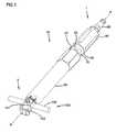
- FIG. 1is a perspective view of one embodiment of a temporary fixation device according to the invention
- FIG. 2is an exploded perspective view of a low profile version of the temporary fixation device of FIG. 1;
- FIG. 3 ais a perspective view of an alternative embodiment of a temporary fixation device of the invention.
- FIG. 3 bis the same embodiment of a temporary fixation device of FIG. 3 b with the driver removed;
- FIG. 3 cis the same embodiment of a temporary fixation device of FIG. 3 a with the outer cannula and driver removed;
- FIG. 4is a longitudinal cross section of the temporary fixation device of FIGS. 3 a - 3 c;
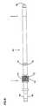
- FIG. 5is a longitudinal cross section view of the outer cannula of the temporary fixation device of FIG. 1;
- FIG. 6is a side view of an inner cannula of a temporary fixation device according to the invention.
- FIG. 7is a longitudinal cross section view through lines 7 — 7 of the inner cannula of FIG. 6;
- FIG. 8is a side view of one embodiment of a fixing member according to the invention.
- FIG. 9is a side view of an embodiment of a handle suitable for use according to the invention.
- FIG. 10illustrates one embodiment of an anti-torque arrangement according to the invention.
- FIG. 11illustrates a pedicle screw with a polyaxial head that can be set according to one embodiment of the invention.
- the present inventionis directed to instruments and methods for increasing the ease and accuracy of positioning vertebral bodies for stabilization and maintaining the integrity of spinal implant systems.
- the inventioncan reduce the number of steps and time required for placement of a vertebral stabilization system and thus reduce the overall surgery time.
- the inventionis suited for use with known spinal implant assemblies including pedicle screws, laminar/transverse process hooks (collectively “hooks”), securing mechanisms, etc. and rods.
- the inventionalso provides unique advantages for pedicle screw systems having heads that provide multiple degrees of rotational or angular freedom.
- the inventionprovides a surgical instrument, particularly, a temporary fixation device (“TFD”), for temporarily fixing a stabilizing rod to a spinal implant prior to permanent fixation of the rod to the implant.
- TFDprovides enhanced control during positioning of the implant before or after temporary fixation.
- the temporary fixation provided by a herein disclosed TFDpermits the surgeon to repeatedly fix and unfix the rod to the implant when maneuvering or correcting the relative position of vertebrae without using the permanent securing arrangement of the implant until a permanent fixation position is established. This ensures the integrity of the permanent securing arrangement of the implant by requiring its use only when a final position is established and not using the permanent securing arrangement during corrective maneuvers that may be made prior to arriving at a final position.
- the ease and convenience provided by the instruments and methods of the inventionpermit the surgeon to align vertebrae into optimal position with greater ease and accuracy and in less time and with less chance of post-operative complications due to prolonged surgical time or compromise the integrity of the implant assembly.
- a “spinal implant assembly”refers to the combination of a spinal implant that can be attached, mounted, clasped, coupled, threaded or otherwise “anchored” to a vertebral body (e.g., posterior or anterior body, transverse process, etc.) and a stabilizing rod. At least one spinal implant is usually anchored to each vertebra to be stabilized.
- the stabilizing rod (“rod”)can be positioned between two or more spinal implants and provides rigid stabilization between the vertebrae. Typically, two implants are positioned on each vertebrae, one on each side of the transverse process, to provide bilateral stabilization. Examples of spinal implants and rods suitable for the invention are known and disclosed in, for example, U.S. Pat. Nos. 6,010,503; 5,964,760; 5,863,293; 5,554,157; and 5,549,608, the entire disclosures of each of which are incorporated herein by reference.
- the term “permanent fixation”refers to the fixation of the vertebrae or implant in a final position with a securing arrangement that secures the rod to the implant at the completion of the surgical procedure and closure of the surgical site.
- temporary fixationrefers to fixation of the vertebrae or implant during surgery in a position that may or may not be the final position at the completion of the surgical procedure.
- a TFD of the inventionis generally only used during surgery and is not left in the patient post-operatively. Prior to the invention, temporary fixation was typically provided during surgery by the permanent securing arrangement that secures the rod to the implant at the completion of the procedure.
- proximal and distalare relative terms, the term “proximal” referring to a location nearest the surgeon and the term “distal” referring to a location farthest from the surgeon.
- proximal endis the end that is typically nearest the surgeon and the distal end nearest the patient.
- FIG. 1is a perspective view of one embodiment of a temporary fixation device (“TFD”) 10 shown mounted to one embodiment of a spinal implant assembly 100 suitable for the invention.
- Spinal implant assembly 100includes spinal implant 101 and stabilizing rod 102 .
- TFD 10has a proximal end 1 , a distal end 2 and a longitudinal axis A—A passing therethrough.
- FIG. 2A shortened version of the TFD 10 of FIG. 1 is illustrated in an exploded perspective view in FIG. 2 and includes an outer cannula 20 , inner cannula 40 , fixing member 60 and driver 80 .
- fixing member 60is sized and configured to pass within lumen 41 of inner cannula 40 .
- Inner cannula 40is sized and configured to pass within lumen 21 of outer cannula 20 .
- Driver 80is sized and configured to pass over outer cannula 20 .
- FIG. 3 ais a perspective view of one embodiment of TFD 10 substantially identical to the embodiments of FIGS. 1 and 2 except that the driver engagement region 26 of outer cannula 20 has a splined configuration 27 a to coaptate with cannula engagement region 81 a of driver 80 as will be further described below.
- FIG. 3 billustrates the TFD 10 of FIG. 3 a with driver 80 removed.
- FIG. 3 cillustrates the TFD 10 of FIGS. 3 a and 3 b with outer cannula 20 removed.
- FIG. 4is a longitudinal cross section view of the TFD 10 of FIG. 3 a.
- the distal end of spinal implant 101includes a hook 103 including a saddle region 104 for anchoring to a vertebral lamina or transverse process.
- rod 102is positioned within rod receiving arrangement 105 comprising cradle region 106 and arms 107 and 108 .
- Arms 107 and 108include a distal thread set 109 and a proximal thread set 110 .
- spinal implant 101includes a longitudinal axis that is concentric with longitudinal axis A—A of TFD 10 when TFD 10 is mounted to spinal implant 101 (see FIGS. 1 and 3 a ).
- rod 102can be securely fixed within cradle region 106 when locking nut 111 is threaded along distal threads 109 such that locking nut surface 112 is snugged tight against rod 102 .
- the threads 113 of locking nut 111are configured to force arms 107 and 108 together against rod 102 as locking nut 111 is distally advanced along distal threads 109 to a permanent tightened position.
- Grooves 116 , 117are present in each of arms 107 , 108 , respectively, between proximal threads 110 and distal threads 109 . Grooves 116 and 117 provide a point at which tabs 118 and 119 of arms 107 and 108 , respectively, can be removed from implant 101 after permanently fixing rod 102 with locking nut 111 .
- FIGS. 2 and 5are longitudinal cross section views through outer cannula 20 ).
- the interior surface 22 at the distal end of outer cannula 20includes a coaptating region 23 having a hexagonal configuration 24 for coaptating with the external hexagonal configuration 120 of locking nut 111 .
- Tab 24 aprovides an inwardly directed force to hold locking nut 111 in place within coaptating region 23 .
- the exterior surface 25 of outer cannula 20also includes a driver engagement region 26 having a hexagonal configuration 27 for engaging cannula engagement region 81 at the distal end of lumen 82 of driver 80 .
- the driver engagement region 26 of TFD 10can have a splined configuration 27 a complimentary to cannula engagement region 81 a of driver 80 as shown in FIGS. 3 a - 3 c.
- FIGS. 1, 3 a , 3 b and 4illustrate that outer cannula 20 can substantially cover the external hexagonal configuration 120 of locking nut 111 when coaptating region 23 is mounted to locking nut 111 .
- the proximal end of driver 80can include a handle receiving region 84 for mounting a handle (not shown) to facilitate rotation of driver 80 .
- Suitable handles for rotating driver 80including torque limiting handles, are known and can be used.
- FIG. 6is a side view of one embodiment of an inner cannula 40 according to the invention and FIG. 7 is a longitudinal cross section of the inner cannula 40 of FIG. 6 taken through line 7 — 7 .
- the interior surface 42 of lumen 41 of inner cannula 40can include threads 43 at the distal end.
- threads 43are sized to threadedly mate with proximal threads 110 of spinal implant 101 .
- outer cannula 20when inner cannula 40 is positioned within lumen 21 of outer cannula 20 , outer cannula 20 is axially movable over inner cannula 40 between a distally advanced and proximally retracted position.
- the limits of the proximally retracted and distally advanced positions, of outer cannula 20are determined by the interaction of inner cannula distal stop 44 and inner cannula proximal stop 45 with outer cannula distal stop 30 and outer cannula proximal stop 31 .
- inner cannula distal stop 44comprises an external helical thread 46 and inner cannula proximal stop 45 comprises ridge 47 .
- Outer cannula distal stop 30comprises an internal helical thread 32 which can threadedly mate with external helical thread 46 of inner cannula 40 .
- the outer cannula proximal stop 31comprises one or more fingers 33 positioned to abut against ridge 47 of inner cannula 40 .
- Axial mobility of outer cannula 20 over inner cannula 40may be best understood by referring to FIGS. 4, 5 and 6 .
- inner cannula 40is passed into outer cannula 20 and axially rotated such that external helical threads 46 of inner cannula distal stop 44 threadedly engage internal helical threads 32 until external helical threads 46 of internal cannula 40 pass distally beyond and disengage from internal helical threads 32 of outer cannula 20 .
- Once external helical threads 46 are advanced distally beyond internal threads 32see FIG.
- outer cannula 20can be slid proximally until fingers 33 of outer cannula proximal stop 31 abuts against ridge 47 of inner cannula proximal stop 45 . From the proximally retracted position, outer cannula 20 can be distally advanced until the proximal aspect 37 of internal helical threads 32 of outer cannula 20 abut against the distal aspect 50 of external helical threads 46 of inner cannula 40 . The relative position of the fingers 33 of outer cannula proximal stop 31 and ridge 47 of inner cannula proximal stop 45 can be seen with outer cannula 20 in the distally advanced position in FIG. 1 and in the proximally retracted position in FIG. 3 b.
- the interior surface 42 of lumen 41 of inner cannula 40also includes an axially directed shoulder 55 .
- Shoulder 55can affirmatively stop distal advancement of inner cannula 40 against the proximal edge 122 of implant 101 when threads 43 of inner cannula 40 are threadedly advanced along thread set 110 of implant 101 .
- fixing member 60includes a distal tip 62 and an operating end 63 including a handle receiving portion 64 configured for receiving a handle such as handle 150 shown in FIG. 9.
- a centering guide 75such as annular collar 76 can be provided to maintain fixing member 60 centered within lumen 41 of inner cannula 40 .
- fixing member 60also includes a portion of a temporary securing arrangement 70 to temporarily secure the fixing member in a position to temporarily fix rod 102 .
- temporary securing arrangement 70includes threads 61 on fixing member 60 which threadedly engage proximal internal threads 71 on inner cannula 40 .
- Threadedly rotating threads 61 of fixing member 60 relative to proximal internal threads 71 of inner cannula 40provides for selective axial advancement and retraction of fixing member 60 within inner cannula 40 to secure fixing member 60 against the surface of rod 102 for temporary fixation of rod 102 in cradle region 106 of spinal implant 101 .
- the illustrated embodimentutilizes threads for advancing, retracting and securing fixing member 60
- alternative temporary securing arrangementscan be used including, for example, a locking cam, pneumatic pressure, etc.
- a spinal implant 101can be anchored to the vertebral body using known procedures (e.g., threads, hooks, etc.).
- a rod securing arrangement, such as locking nut 111can be positioned into the coaptating region 23 of outer cannula 20 of TFD 10 .
- driver 80 of TFD 10may be absent and thus TFD 10 appears substantially as shown in FIGS. 1 and 3 b .
- Locking nut 111can then be threaded beyond distal threads 109 and just started onto proximal threads 110 of arms 107 and 108 by rotating outer cannula 20 .
- the appearance of TFD 10 relative to spinal implant 101will be substantially as shown in FIG. 3 b .
- inner threads 43 at the distal end of lumen 41 of inner cannula 40begin to engage proximal threads 110 .
- outer cannula 20has been removed to visualize the appearance of the relationship between the inner cannula 40 and spinal implant 101 at this stage of the procedure.
- Rod 102can then be positioned in cradle region 106 .
- a handlesuch as handle 150 (FIG. 9) can be mounted to handle receiving portion 64 at the proximal end of fixing member 60 and fixing member 60 rotated until fixing member 60 exerts a sufficient force to immobilize rod 102 with the force exerted by fixing member 60 preferably being exerted along an axis concentric with the longitudinal axis A—A of TFD 10 and spinal implant 101 .
- Fixing member 60can then be alternately loosened and tightened as necessary during correction maneuvers until the vertebral bodies are in desired position for permanent fixation.
- fixing member 60In addition to providing temporary fixation, fixing member 60 also ensures that the rod 101 is fully seated within the cradle 106 of the spinal implant 101 . It will be appreciated that at this stage of the procedure, although there may be repeated loosening and tightening of fixing member 60 against rod 102 , the locking nut 111 that will maintain permanent fixation of rod 102 within spinal implant 101 post-operatively, has not yet been passed over the distal threads 109 , leaving these threads and threads 113 of locking nut 111 in a pristine condition until finally used for permanent fixation.
- TFD 10provides for temporary fixation of rod 102 within cradle region 106 to permit the surgeon to secure and unsecure rod 102 within cradle region 106 without forcing arms 107 and 108 together against rod 102 with locking nut 111 until a final position of rod 102 is determined for permanent fixation.
- handle 150can be removed from fixing member 60 .
- Driver 80can then be passed onto TFD 10 such that cannula engaging region 81 of driver 80 engages the corresponding exterior surface contour 26 of outer cannula 20 .
- the outer cannula 20can then be rotated by driver 80 to advance locking nut 111 distally along distal threads 109 to secure surface 112 of locking nut 111 against rod 102 .
- a handlesuch as handle 150 (FIG. 9) or a “T” handle or other known handle can be used to rotate driver 80 .
- a torque limiting wrenchcan be used to finally tighten all locking nuts on all implants used.
- the appearance of the spinal assembly 100 and TFD 10 at the final stage of the procedureis substantially as shown in FIG. 1 . Note that at this stage, axially extending fingers 33 at the proximal end of outer cannula 20 are distally advanced away from ridge 47 of outer cannula 20 .
- fixing member 60is threadedly retracted away from rod 102 .
- the outer cannula 20can then be proximally retracted such that the coaptating region 23 at the distal end of outer cannula 20 is free from locking nut 111 .
- Inner cannula 40can then unthreaded from the proximal thread set 110 of spinal implant 101 . If present, tabs 118 and 119 of arms 107 and 108 can be broken free from the spinal implant at grooves 116 and 117 , respectively. The surgical incision can then be closed using known methods.
- FIG. 10illustrates one embodiment of an anti-torque arrangement 200 suitable for use with a TFD 10 according to the invention.
- anti-torque arrangement 200can include a handle 201 for gripping and a rod stabilizing arrangement 202 for grasping a portion of rod 102 .
- handle 150can be used to provide an anti-torque force in the direction of arrow 206 to counteract the forces on the assembly 100 during final tightening of the locking nuts.
- a TFD 10can be advantageously used to “set” or cold fuse the polyaxial head of a pedicle screw having a polyaxial head, such as disclosed in U.S. Pat. Nos. 5,964,760 and 6,010,503.
- FIG. 11illustrates one embodiment of a pedicle screw 300 having a polyaxial head 301 .
- the mobility of polyaxial head 301is set when locking nut 302 is advanced distally along distal threads 303 to force rod 304 against insert 305 which tightens around screw head 306 to set polyaxial head 301 in a fixed position.
- locking nut 302can be loosened, if it is necessary to reposition rod 304 , without concern that the position of polyaxial head 301 will change.
- a TFD 10can be used to set polyaxial head 301 to maintain distal thread set 303 in a pristine condition until permanent fixation.
- internal threads 43 of inner cannula 40are threaded onto proximal threads 310 of pedicle screw 300 .
- Fixing member 60can then be distally advanced to exert a force against rod 304 and insert 305 to set polyaxial head 301 in a fixed position on screw head 306 .
- Corrective maneuverscan then be performed with TFD 10 as described above without movement of the position of polyaxial head 301 and without the need to advance locking nut 302 along distal threads 303 , until a permanent fixation position is determined.
Landscapes
- Health & Medical Sciences (AREA)
- Orthopedic Medicine & Surgery (AREA)
- Neurology (AREA)
- Life Sciences & Earth Sciences (AREA)
- Surgery (AREA)
- Heart & Thoracic Surgery (AREA)
- Engineering & Computer Science (AREA)
- Biomedical Technology (AREA)
- Nuclear Medicine, Radiotherapy & Molecular Imaging (AREA)
- Medical Informatics (AREA)
- Molecular Biology (AREA)
- Animal Behavior & Ethology (AREA)
- General Health & Medical Sciences (AREA)
- Public Health (AREA)
- Veterinary Medicine (AREA)
- Surgical Instruments (AREA)
- Prostheses (AREA)
Abstract
Description
Claims (14)
Priority Applications (2)
| Application Number | Priority Date | Filing Date | Title |
|---|---|---|---|
| US09/676,622US6743231B1 (en) | 2000-10-02 | 2000-10-02 | Temporary spinal fixation apparatuses and methods |
| US10/821,617US7618440B2 (en) | 2000-10-02 | 2004-04-09 | Temporary spinal fixation apparatuses and methods |
Applications Claiming Priority (1)
| Application Number | Priority Date | Filing Date | Title |
|---|---|---|---|
| US09/676,622US6743231B1 (en) | 2000-10-02 | 2000-10-02 | Temporary spinal fixation apparatuses and methods |
Related Child Applications (1)
| Application Number | Title | Priority Date | Filing Date |
|---|---|---|---|
| US10/821,617ContinuationUS7618440B2 (en) | 2000-10-02 | 2004-04-09 | Temporary spinal fixation apparatuses and methods |
Publications (1)
| Publication Number | Publication Date |
|---|---|
| US6743231B1true US6743231B1 (en) | 2004-06-01 |
Family
ID=32326996
Family Applications (2)
| Application Number | Title | Priority Date | Filing Date |
|---|---|---|---|
| US09/676,622Expired - Fee RelatedUS6743231B1 (en) | 2000-10-02 | 2000-10-02 | Temporary spinal fixation apparatuses and methods |
| US10/821,617Expired - Fee RelatedUS7618440B2 (en) | 2000-10-02 | 2004-04-09 | Temporary spinal fixation apparatuses and methods |
Family Applications After (1)
| Application Number | Title | Priority Date | Filing Date |
|---|---|---|---|
| US10/821,617Expired - Fee RelatedUS7618440B2 (en) | 2000-10-02 | 2004-04-09 | Temporary spinal fixation apparatuses and methods |
Country Status (1)
| Country | Link |
|---|---|
| US (2) | US6743231B1 (en) |
Cited By (186)
| Publication number | Priority date | Publication date | Assignee | Title |
|---|---|---|---|---|
| US20040039384A1 (en)* | 2002-08-21 | 2004-02-26 | Boehm Frank H. | Device and method for pertcutaneous placement of lumbar pedicle screws and connecting rods |
| US20040147936A1 (en)* | 2003-01-28 | 2004-07-29 | Rosenberg William S. | Spinal rod approximator |
| US20040158247A1 (en)* | 2003-02-07 | 2004-08-12 | Arthit Sitiso | Polyaxial pedicle screw system |
| US20040254576A1 (en)* | 2003-06-16 | 2004-12-16 | Depuy Acromed, Inc. | Rod reduction nut and driver tool |
| US20040267275A1 (en)* | 2003-06-26 | 2004-12-30 | Cournoyer John R. | Spinal implant holder and rod reduction systems and methods |
| US20050033299A1 (en)* | 2002-09-06 | 2005-02-10 | Shluzas Alan E. | Surgical instrument for moving a vertebra |
| US20050038438A1 (en)* | 2003-08-11 | 2005-02-17 | Depuy Acromed, Inc. | Distraction screw |
| US20050059969A1 (en)* | 2003-09-17 | 2005-03-17 | Depuy Acromed, Inc. | Rod approximator |
| US20050131422A1 (en)* | 2003-12-16 | 2005-06-16 | Anderson David G. | Methods and devices for spinal fixation element placement |
| US20050131421A1 (en)* | 2003-12-16 | 2005-06-16 | Anderson David G. | Methods and devices for minimally invasive spinal fixation element placement |
| US20050137593A1 (en)* | 2000-10-02 | 2005-06-23 | Sulzer Spine-Tech Inc. | Temporary spinal fixation apparatuses and methods |
| US20050149053A1 (en)* | 2003-12-17 | 2005-07-07 | Varieur Michael S. | Instruments and methods for bone anchor engagement and spinal rod reduction |
| US20050215999A1 (en)* | 2004-03-19 | 2005-09-29 | Depuy Spine, Inc. | Spinal fixation element and methods |
| US20060009775A1 (en)* | 2004-07-06 | 2006-01-12 | Brian Dec | Spinal rod insertion instrument |
| US20060025768A1 (en)* | 2003-07-03 | 2006-02-02 | Andy Iott | Top loading spinal fixation device and instruments for loading and handling the same |
| US20060036260A1 (en)* | 2004-08-06 | 2006-02-16 | Runco Thomas J | Instrument for guiding a rod into an implant in a spinal fixation system |
| US20060036244A1 (en)* | 2003-10-21 | 2006-02-16 | Innovative Spinal Technologies | Implant assembly and method for use in an internal structure stabilization system |
| US20060074445A1 (en)* | 2004-09-29 | 2006-04-06 | David Gerber | Less invasive surgical system and methods |
| US20060095035A1 (en)* | 2004-11-03 | 2006-05-04 | Jones Robert J | Instruments and methods for reduction of vertebral bodies |
| US20060111713A1 (en)* | 2004-11-23 | 2006-05-25 | Jackson Roger P | Spinal fixation tool set and method |
| US20060149236A1 (en)* | 2004-12-30 | 2006-07-06 | Barry Mark A | System and method for aligning vertebrae in the amelioration of aberrant spinal column deviation conditions |
| US20060195092A1 (en)* | 2004-12-30 | 2006-08-31 | Barry Mark A | System and method for aligning vertebrae in the amelioration of aberrant spinal column deviation conditions |
| US20060200131A1 (en)* | 2005-03-04 | 2006-09-07 | Depuy Spine Sarl | Constrained motion bone screw assembly |
| US20060200132A1 (en)* | 2005-03-04 | 2006-09-07 | Chao Nam T | Instruments and methods for manipulating a vertebra |
| US20060293690A1 (en)* | 2005-05-23 | 2006-12-28 | Custom Spine, Inc. | Rod reducer |
| US20070078460A1 (en)* | 2005-08-25 | 2007-04-05 | Robert Frigg | Methods of spinal fixation and instrumentation |
| US20070161998A1 (en)* | 2005-10-28 | 2007-07-12 | Dale Whipple | Instruments and Methods For Manipulating A Spinal Rod |
| US20070270842A1 (en)* | 2006-04-11 | 2007-11-22 | Bankoski Brian R | Minimally invasive fixation sysyem |
| US20070288011A1 (en)* | 2006-04-18 | 2007-12-13 | Joseph Nicholas Logan | Spinal Rod System |
| US20080177269A1 (en)* | 2006-12-07 | 2008-07-24 | Seelig Matthew E | Apparatus and methods for reduction of vertebral bodies in a spine |
| US20080234765A1 (en)* | 2007-03-13 | 2008-09-25 | Depuy Spine, Inc. | Rod reduction methods and devices |
| US20080234739A1 (en)* | 2007-03-13 | 2008-09-25 | Zimmer Spine, Inc. | Dynamic spinal stabilization system and method of using the same |
| US20080234737A1 (en)* | 2007-03-16 | 2008-09-25 | Zimmer Spine, Inc. | Dynamic spinal stabilization system and method of using the same |
| US20080243190A1 (en)* | 2007-03-29 | 2008-10-02 | Depuy Spine, Inc. | In-line rod reduction device and methods |
| US20080300638A1 (en)* | 2006-11-20 | 2008-12-04 | Depuy Spine, Inc. | Break-off screw extensions |
| US7491207B2 (en) | 2004-04-12 | 2009-02-17 | Synthes Usa, Llc | Rod persuader |
| US20090177196A1 (en)* | 2008-01-09 | 2009-07-09 | Applied Spine Technologies, Inc. | Medical Instrument For Rod Positioning |
| US20090228056A1 (en)* | 2004-02-27 | 2009-09-10 | Jackson Roger P | Orthopedic implant rod reduction tool set and method |
| US20100121386A1 (en)* | 2008-11-05 | 2010-05-13 | Warsaw Orthopedic, Inc. | Progressive Reduction Instrument for Reduction of a Vertebral Rod and Method of Use |
| US7722651B2 (en) | 2005-10-21 | 2010-05-25 | Depuy Spine, Inc. | Adjustable bone screw assembly |
| US20100185242A1 (en)* | 2009-01-22 | 2010-07-22 | David Barry | Rod Coercer |
| US20100185248A1 (en)* | 2009-01-22 | 2010-07-22 | David Barry | Rod Coercer |
| US20100292742A1 (en)* | 2009-05-13 | 2010-11-18 | Stad Shawn D | Torque Limited Instrument For Manipulating A Spinal Rod Relative to a Bone Anchor |
| US7842044B2 (en) | 2003-12-17 | 2010-11-30 | Depuy Spine, Inc. | Instruments and methods for bone anchor engagement and spinal rod reduction |
| US20110034961A1 (en)* | 2007-07-26 | 2011-02-10 | Depuy Spine, Inc. | Spinal rod reduction instruments and methods for use |
| US7887539B2 (en) | 2003-01-24 | 2011-02-15 | Depuy Spine, Inc. | Spinal rod approximators |
| US7918857B2 (en) | 2006-09-26 | 2011-04-05 | Depuy Spine, Inc. | Minimally invasive bone anchor extensions |
| US20110093015A1 (en)* | 2009-10-20 | 2011-04-21 | Ramsay Christopher L | Spinal implant with a flexible extension element |
| US7967826B2 (en) | 2003-10-21 | 2011-06-28 | Theken Spine, Llc | Connector transfer tool for internal structure stabilization systems |
| US8066739B2 (en) | 2004-02-27 | 2011-11-29 | Jackson Roger P | Tool system for dynamic spinal implants |
| US8105368B2 (en) | 2005-09-30 | 2012-01-31 | Jackson Roger P | Dynamic stabilization connecting member with slitted core and outer sleeve |
| US8152810B2 (en) | 2004-11-23 | 2012-04-10 | Jackson Roger P | Spinal fixation tool set and method |
| US8216241B2 (en) | 2005-06-02 | 2012-07-10 | Depuy Spine, Inc. | Instruments and methods for manipulating a spinal fixation element |
| US8348952B2 (en) | 2006-01-26 | 2013-01-08 | Depuy International Ltd. | System and method for cooling a spinal correction device comprising a shape memory material for corrective spinal surgery |
| US8353932B2 (en) | 2005-09-30 | 2013-01-15 | Jackson Roger P | Polyaxial bone anchor assembly with one-piece closure, pressure insert and plastic elongate member |
| US8366745B2 (en) | 2007-05-01 | 2013-02-05 | Jackson Roger P | Dynamic stabilization assembly having pre-compressed spacers with differential displacements |
| US8388659B1 (en) | 2008-10-17 | 2013-03-05 | Theken Spine, Llc | Spondylolisthesis screw and instrument for implantation |
| US8394133B2 (en) | 2004-02-27 | 2013-03-12 | Roger P. Jackson | Dynamic fixation assemblies with inner core and outer coil-like member |
| US8403991B2 (en) | 2005-05-06 | 2013-03-26 | Titan Spine Llc | Implant with critical ratio of load bearing surface area to central opening area |
| EP2574297A1 (en)* | 2011-09-30 | 2013-04-03 | Biedermann Technologies GmbH & Co. KG | Bone anchoring device and tool cooperating with such a bone anchoring device |
| US8414588B2 (en) | 2007-10-04 | 2013-04-09 | Depuy Spine, Inc. | Methods and devices for minimally invasive spinal connection element delivery |
| US8414614B2 (en) | 2005-10-22 | 2013-04-09 | Depuy International Ltd | Implant kit for supporting a spinal column |
| US8425563B2 (en) | 2006-01-13 | 2013-04-23 | Depuy International Ltd. | Spinal rod support kit |
| US8430914B2 (en) | 2007-10-24 | 2013-04-30 | Depuy Spine, Inc. | Assembly for orthopaedic surgery |
| US8435302B2 (en) | 2005-05-06 | 2013-05-07 | Titan Spine, Llc | Instruments and interbody spinal implants enhancing disc space distraction |
| US8475498B2 (en) | 2007-01-18 | 2013-07-02 | Roger P. Jackson | Dynamic stabilization connecting member with cord connection |
| US8480749B2 (en) | 2005-05-06 | 2013-07-09 | Titan Spine, Llc | Friction fit and vertebral endplate-preserving spinal implant |
| US8496710B2 (en) | 2005-05-06 | 2013-07-30 | Titan Spine, Llc | Interbody spinal implant having a roughened surface topography |
| US8545538B2 (en) | 2005-12-19 | 2013-10-01 | M. Samy Abdou | Devices and methods for inter-vertebral orthopedic device placement |
| US8545568B2 (en) | 2005-05-06 | 2013-10-01 | Titan Spine, Llc | Method of using instruments and interbody spinal implants to enhance distraction |
| US8551176B2 (en) | 2005-05-06 | 2013-10-08 | Titan Spine, Llc | Spinal implant having a passage for enhancing contact between bone graft material and cortical endplate bone |
| US8556904B2 (en) | 2011-05-05 | 2013-10-15 | Warsaw Orthopedic, Inc. | Anchors extender assemblies and methods for using |
| US8562684B2 (en) | 2005-05-06 | 2013-10-22 | Titan Spine, Llc | Endplate-preserving spinal implant with an integration plate having a roughened surface topography |
| US8562685B2 (en) | 2005-05-06 | 2013-10-22 | Titan Spine, Llc | Spinal implant and integration plate for optimizing vertebral endplate contact load-bearing edges |
| US8585765B2 (en) | 2005-05-06 | 2013-11-19 | Titan Spine, Llc | Endplate-preserving spinal implant having a raised expulsion-resistant edge |
| US8585767B2 (en) | 2005-05-06 | 2013-11-19 | Titan Spine, Llc | Endplate-preserving spinal implant with an integration plate having durable connectors |
| US8585766B2 (en) | 2005-05-06 | 2013-11-19 | Titan Spine, Llc | Endplate-preserving spinal implant with an integration plate having durable connectors |
| US8591560B2 (en) | 2005-09-30 | 2013-11-26 | Roger P. Jackson | Dynamic stabilization connecting member with elastic core and outer sleeve |
| US8591590B2 (en) | 2005-05-06 | 2013-11-26 | Titan Spine, Llc | Spinal implant having a transverse aperture |
| US8608746B2 (en) | 2008-03-10 | 2013-12-17 | DePuy Synthes Products, LLC | Derotation instrument with reduction functionality |
| US8617248B2 (en) | 2005-05-06 | 2013-12-31 | Titan Spine, Llc | Spinal implant having variable ratios of the integration surface area to the axial passage area |
| US8685029B2 (en) | 2010-09-27 | 2014-04-01 | DePuy Synthes Products, LLC | Rod reduction instrument and methods of rod reduction |
| US8709015B2 (en) | 2008-03-10 | 2014-04-29 | DePuy Synthes Products, LLC | Bilateral vertebral body derotation system |
| US8758442B2 (en) | 2005-05-06 | 2014-06-24 | Titan Spine, Llc | Composite implants having integration surfaces composed of a regular repeating pattern |
| US8758443B2 (en) | 2005-05-06 | 2014-06-24 | Titan Spine, Llc | Implants with integration surfaces having regular repeating surface patterns |
| US8790348B2 (en) | 2007-09-28 | 2014-07-29 | Depuy Spine, Inc. | Dual pivot instrument for reduction of a fixation element and method of use |
| US8814939B2 (en) | 2005-05-06 | 2014-08-26 | Titan Spine, Llc | Implants having three distinct surfaces |
| US8845649B2 (en) | 2004-09-24 | 2014-09-30 | Roger P. Jackson | Spinal fixation tool set and method for rod reduction and fastener insertion |
| US8852239B2 (en) | 2013-02-15 | 2014-10-07 | Roger P Jackson | Sagittal angle screw with integral shank and receiver |
| US8870928B2 (en) | 2002-09-06 | 2014-10-28 | Roger P. Jackson | Helical guide and advancement flange with radially loaded lip |
| US8911478B2 (en) | 2012-11-21 | 2014-12-16 | Roger P. Jackson | Splay control closure for open bone anchor |
| US8926672B2 (en) | 2004-11-10 | 2015-01-06 | Roger P. Jackson | Splay control closure for open bone anchor |
| US8926670B2 (en) | 2003-06-18 | 2015-01-06 | Roger P. Jackson | Polyaxial bone screw assembly |
| US8979904B2 (en) | 2007-05-01 | 2015-03-17 | Roger P Jackson | Connecting member with tensioned cord, low profile rigid sleeve and spacer with torsion control |
| US8992619B2 (en) | 2011-11-01 | 2015-03-31 | Titan Spine, Llc | Microstructured implant surfaces |
| US8992622B2 (en) | 2005-05-06 | 2015-03-31 | Titan Spine, Llc | Interbody spinal implant having a roughened surface topography |
| US8998959B2 (en) | 2009-06-15 | 2015-04-07 | Roger P Jackson | Polyaxial bone anchors with pop-on shank, fully constrained friction fit retainer and lock and release insert |
| US8998960B2 (en) | 2004-11-10 | 2015-04-07 | Roger P. Jackson | Polyaxial bone screw with helically wound capture connection |
| US20150112392A1 (en)* | 2013-10-18 | 2015-04-23 | Warsaw Orthopedic, Inc. | Spinal correction method and system |
| US9044274B2 (en) | 2010-12-01 | 2015-06-02 | Amendia, Inc. | Bone screw system |
| US9050139B2 (en) | 2004-02-27 | 2015-06-09 | Roger P. Jackson | Orthopedic implant rod reduction tool set and method |
| US9050148B2 (en) | 2004-02-27 | 2015-06-09 | Roger P. Jackson | Spinal fixation tool attachment structure |
| US9125756B2 (en) | 2005-05-06 | 2015-09-08 | Titan Spine, Llc | Processes for producing regular repeating patterns on surfaces of interbody devices |
| US9144444B2 (en) | 2003-06-18 | 2015-09-29 | Roger P Jackson | Polyaxial bone anchor with helical capture connection, insert and dual locking assembly |
| US9168147B2 (en) | 2005-05-06 | 2015-10-27 | Titan Spine, Llc | Self-deploying locking screw retention device |
| US9168069B2 (en) | 2009-06-15 | 2015-10-27 | Roger P. Jackson | Polyaxial bone anchor with pop-on shank and winged insert with lower skirt for engaging a friction fit retainer |
| US9192415B1 (en) | 2008-02-06 | 2015-11-24 | Nuvasive, Inc. | Systems and methods for holding and implanting bone anchors |
| US9198698B1 (en) | 2011-02-10 | 2015-12-01 | Nuvasive, Inc. | Minimally invasive spinal fixation system and related methods |
| US9216041B2 (en) | 2009-06-15 | 2015-12-22 | Roger P. Jackson | Spinal connecting members with tensioned cords and rigid sleeves for engaging compression inserts |
| US9216039B2 (en) | 2004-02-27 | 2015-12-22 | Roger P. Jackson | Dynamic spinal stabilization assemblies, tool set and method |
| US9289248B2 (en) | 2009-11-06 | 2016-03-22 | Kevin Seex | Assembly with offset allowing vertebral distraction by axial rotation of a concentric member |
| US9308027B2 (en) | 2005-05-27 | 2016-04-12 | Roger P Jackson | Polyaxial bone screw with shank articulation pressure insert and method |
| US9314274B2 (en) | 2011-05-27 | 2016-04-19 | DePuy Synthes Products, Inc. | Minimally invasive spinal fixation system including vertebral alignment features |
| US9339301B2 (en) | 2004-12-30 | 2016-05-17 | Mark A. Barry | System and method for aligning vertebrae in the amelioration of aberrant spinal column deviation conditions |
| US9402663B2 (en) | 2010-04-23 | 2016-08-02 | DePuy Synthes Products, Inc. | Minimally invasive instrument set, devices and related methods |
| US9439692B1 (en) | 2015-10-09 | 2016-09-13 | Spine Wave, Inc. | Minimally invasive spinal fixation system and method therefor |
| US9439683B2 (en) | 2007-01-26 | 2016-09-13 | Roger P Jackson | Dynamic stabilization member with molded connection |
| US9451993B2 (en) | 2014-01-09 | 2016-09-27 | Roger P. Jackson | Bi-radial pop-on cervical bone anchor |
| US9451989B2 (en) | 2007-01-18 | 2016-09-27 | Roger P Jackson | Dynamic stabilization members with elastic and inelastic sections |
| US9452000B2 (en) | 2013-10-07 | 2016-09-27 | K2M, Inc. | Rod reducer |
| US9486256B1 (en) | 2013-03-15 | 2016-11-08 | Nuvasive, Inc. | Rod reduction assemblies and related methods |
| US9498349B2 (en) | 2012-10-09 | 2016-11-22 | Titan Spine, Llc | Expandable spinal implant with expansion wedge and anchor |
| US9504496B2 (en) | 2009-06-15 | 2016-11-29 | Roger P. Jackson | Polyaxial bone anchor with pop-on shank, friction fit retainer and winged insert |
| US9566092B2 (en) | 2013-10-29 | 2017-02-14 | Roger P. Jackson | Cervical bone anchor with collet retainer and outer locking sleeve |
| US9597119B2 (en) | 2014-06-04 | 2017-03-21 | Roger P. Jackson | Polyaxial bone anchor with polymer sleeve |
| US9615935B2 (en) | 2014-01-30 | 2017-04-11 | Titan Spine, Llc | Thermally activated shape memory spring assemblies for implant expansion |
| US9636146B2 (en) | 2012-01-10 | 2017-05-02 | Roger P. Jackson | Multi-start closures for open implants |
| US9642721B2 (en) | 2012-10-02 | 2017-05-09 | Titan Spine, Llc | Implants with self-deploying anchors |
| US9655745B2 (en) | 2005-05-06 | 2017-05-23 | Titan Spine, Llc | Methods for manufacturing implants having integration surfaces |
| US9668771B2 (en) | 2009-06-15 | 2017-06-06 | Roger P Jackson | Soft stabilization assemblies with off-set connector |
| US9668789B2 (en) | 2013-03-15 | 2017-06-06 | Ebi, Llc | Reduction instrument, surgical assembly including a reduction instrument and related method |
| US9717533B2 (en) | 2013-12-12 | 2017-08-01 | Roger P. Jackson | Bone anchor closure pivot-splay control flange form guide and advancement structure |
| US9808281B2 (en) | 2009-05-20 | 2017-11-07 | DePuy Synthes Products, Inc. | Patient-mounted retraction |
| EP2854674B1 (en) | 2012-05-28 | 2017-11-15 | Safe Orthopeadics | Instrument system for carrying out a surgical procedure on the vertebrae comprising temporary immobilization means |
| US9848995B2 (en) | 2012-03-20 | 2017-12-26 | Titan Spine Llc | Process for fabricating bioactive vertebral endplate bone-contacting surfaces on a spinal implant |
| US9907574B2 (en) | 2008-08-01 | 2018-03-06 | Roger P. Jackson | Polyaxial bone anchors with pop-on shank, friction fit fully restrained retainer, insert and tool receiving features |
| US9918745B2 (en) | 2009-06-15 | 2018-03-20 | Roger P. Jackson | Polyaxial bone anchor with pop-on shank and winged insert with friction fit compressive collet |
| US9936986B2 (en) | 2013-05-06 | 2018-04-10 | Life Spine, Inc. | Systems and methods for spinal rod insertion and reduction |
| US9943344B2 (en) | 2015-01-15 | 2018-04-17 | K2M, Inc. | Rod reducer |
| EP2526888B1 (en) | 2009-12-28 | 2018-04-18 | Safe Orthopeadics | Device for spinal surgery |
| US9974577B1 (en) | 2015-05-21 | 2018-05-22 | Nuvasive, Inc. | Methods and instruments for performing leveraged reduction during single position spine surgery |
| US10058354B2 (en) | 2013-01-28 | 2018-08-28 | Roger P. Jackson | Pivotal bone anchor assembly with frictional shank head seating surfaces |
| US10064658B2 (en) | 2014-06-04 | 2018-09-04 | Roger P. Jackson | Polyaxial bone anchor with insert guides |
| US10117678B2 (en) | 2015-05-28 | 2018-11-06 | K2M, Inc. | Surgical system for bone screw insertion and rod reduction |
| US10136927B1 (en) | 2013-03-15 | 2018-11-27 | Nuvasive, Inc. | Rod reduction assemblies and related methods |
| US10258382B2 (en) | 2007-01-18 | 2019-04-16 | Roger P. Jackson | Rod-cord dynamic connection assemblies with slidable bone anchor attachment members along the cord |
| US10299839B2 (en) | 2003-12-16 | 2019-05-28 | Medos International Sárl | Percutaneous access devices and bone anchor assemblies |
| US10349983B2 (en) | 2003-05-22 | 2019-07-16 | Alphatec Spine, Inc. | Pivotal bone anchor assembly with biased bushing for pre-lock friction fit |
| US10383660B2 (en) | 2007-05-01 | 2019-08-20 | Roger P. Jackson | Soft stabilization assemblies with pretensioned cords |
| US10398481B2 (en) | 2016-10-03 | 2019-09-03 | Nuvasive, Inc. | Spinal fixation system |
| US10405896B2 (en) | 2015-04-30 | 2019-09-10 | K2M, Inc. | Rod reducer |
| US10485590B2 (en) | 2017-01-18 | 2019-11-26 | K2M, Inc. | Rod reducing device |
| US10492833B2 (en) | 2016-08-24 | 2019-12-03 | Biedermann Technologies Gmbh & Co. Kg | Polyaxial bone anchoring device and system of an instrument and a polyaxial bone anchoring device |
| US10524843B2 (en) | 2016-05-06 | 2020-01-07 | K2M, Inc. | Rotation shaft for a rod reducer |
| US10543107B2 (en) | 2009-12-07 | 2020-01-28 | Samy Abdou | Devices and methods for minimally invasive spinal stabilization and instrumentation |
| US10548740B1 (en) | 2016-10-25 | 2020-02-04 | Samy Abdou | Devices and methods for vertebral bone realignment |
| US10575961B1 (en) | 2011-09-23 | 2020-03-03 | Samy Abdou | Spinal fixation devices and methods of use |
| US10695105B2 (en) | 2012-08-28 | 2020-06-30 | Samy Abdou | Spinal fixation devices and methods of use |
| US10729469B2 (en) | 2006-01-09 | 2020-08-04 | Roger P. Jackson | Flexible spinal stabilization assembly with spacer having off-axis core member |
| US10751090B2 (en) | 2016-08-04 | 2020-08-25 | Biedermann Technologies Gmbh & Co. Kg | Polyaxial bone anchoring device and system including an instrument and a polyaxial bone anchoring device |
| US10857003B1 (en) | 2015-10-14 | 2020-12-08 | Samy Abdou | Devices and methods for vertebral stabilization |
| US10888356B2 (en) | 2013-05-13 | 2021-01-12 | Neo Medical S.A. | Orthopedic implant kit |
| US10918498B2 (en) | 2004-11-24 | 2021-02-16 | Samy Abdou | Devices and methods for inter-vertebral orthopedic device placement |
| EP3791796A1 (en) | 2019-09-12 | 2021-03-17 | Kevin Seex | Distraction and retraction assembly incorpcorating locking feature |
| US10973648B1 (en) | 2016-10-25 | 2021-04-13 | Samy Abdou | Devices and methods for vertebral bone realignment |
| US10973556B2 (en) | 2008-06-17 | 2021-04-13 | DePuy Synthes Products, Inc. | Adjustable implant assembly |
| US11006982B2 (en) | 2012-02-22 | 2021-05-18 | Samy Abdou | Spinous process fixation devices and methods of use |
| US11051861B2 (en) | 2018-06-13 | 2021-07-06 | Nuvasive, Inc. | Rod reduction assemblies and related methods |
| US11090088B2 (en) | 2018-03-06 | 2021-08-17 | Biedermann Technologies Gmbh & Co. Kg | Polyaxial bone anchoring device and system including an instrument and a polyaxial bone anchoring device |
| US11096796B2 (en) | 2005-05-06 | 2021-08-24 | Titan Spine, Llc | Interbody spinal implant having a roughened surface topography on one or more internal surfaces |
| US11173040B2 (en) | 2012-10-22 | 2021-11-16 | Cogent Spine, LLC | Devices and methods for spinal stabilization and instrumentation |
| US11179248B2 (en) | 2018-10-02 | 2021-11-23 | Samy Abdou | Devices and methods for spinal implantation |
| US11229457B2 (en) | 2009-06-15 | 2022-01-25 | Roger P. Jackson | Pivotal bone anchor assembly with insert tool deployment |
| US11234745B2 (en) | 2005-07-14 | 2022-02-01 | Roger P. Jackson | Polyaxial bone screw assembly with partially spherical screw head and twist in place pressure insert |
| US11241261B2 (en) | 2005-09-30 | 2022-02-08 | Roger P Jackson | Apparatus and method for soft spinal stabilization using a tensionable cord and releasable end structure |
| US11291482B2 (en) | 2019-03-21 | 2022-04-05 | Medos International Sarl | Rod reducers and related methods |
| US11291481B2 (en) | 2019-03-21 | 2022-04-05 | Medos International Sarl | Rod reducers and related methods |
| US11369418B2 (en) | 2017-10-25 | 2022-06-28 | Biedermann Technologies Gmbh & Co. Kg | Polyaxial bone anchoring device |
| US11419642B2 (en) | 2003-12-16 | 2022-08-23 | Medos International Sarl | Percutaneous access devices and bone anchor assemblies |
| USD1004774S1 (en) | 2019-03-21 | 2023-11-14 | Medos International Sarl | Kerrison rod reducer |
| US11832855B2 (en) | 2017-12-15 | 2023-12-05 | Medos International Sårl | Unilateral implant holders and related methods |
| US12127776B2 (en) | 2019-07-02 | 2024-10-29 | Neo Medical Sa | Method, device, and system for preventing lateral stress on bone structures resulting from off-axis forces caused by screw driver and screw extender |
| US12171471B2 (en)* | 2022-06-01 | 2024-12-24 | Socko Medical Co., Ltd. | Bone screw kit |
| US12318121B2 (en) | 2020-11-09 | 2025-06-03 | Medos International Sàrl | Biplanar forceps reducers and methods of use |
| US12414803B2 (en) | 2019-03-26 | 2025-09-16 | Neo Medical Sa | System for tightening an orthopedic set screw at two different torque levels |
| US12440248B2 (en) | 2022-06-28 | 2025-10-14 | DePuy Synthes Products, Inc. | Minimally invasive instrument set, devices, and related methods |
Families Citing this family (30)
| Publication number | Priority date | Publication date | Assignee | Title |
|---|---|---|---|---|
| US7955355B2 (en) | 2003-09-24 | 2011-06-07 | Stryker Spine | Methods and devices for improving percutaneous access in minimally invasive surgeries |
| US8002798B2 (en) | 2003-09-24 | 2011-08-23 | Stryker Spine | System and method for spinal implant placement |
| US7588588B2 (en) | 2003-10-21 | 2009-09-15 | Innovative Spinal Technologies | System and method for stabilizing of internal structures |
| US7591836B2 (en)* | 2004-07-30 | 2009-09-22 | Zimmer Spine, Inc. | Surgical devices and methods for vertebral shifting utilizing spinal fixation systems |
| US7875065B2 (en) | 2004-11-23 | 2011-01-25 | Jackson Roger P | Polyaxial bone screw with multi-part shank retainer and pressure insert |
| ATE536821T1 (en) | 2004-11-23 | 2011-12-15 | Roger P Jackson | POLYAXIAL BONE SCREW WITH MULTIPLE SHAFT FIXATION |
| WO2008024937A2 (en) | 2006-08-23 | 2008-02-28 | Pioneer Surgical Technology, Inc. | Minimally invasive surgical system |
| EP1858422A4 (en)* | 2005-02-23 | 2011-12-28 | Pioneer Surgical Technology Inc | Minimally invasive surgical system |
| US7559930B2 (en)* | 2006-01-26 | 2009-07-14 | Warsaw Orthopedic, Inc. | Surgical tool and method with an actuation mechanism for controlling reciprocation and locking of an anti-rotation member relative to an engagement member for facilitating positioning of an intervertebral device |
| EP1981422B1 (en)* | 2006-02-06 | 2018-10-24 | Stryker European Holdings I, LLC | Rod contouring apparatus for percutaneous pedicle screw extension |
| EP2073734A1 (en)* | 2006-09-25 | 2009-07-01 | Stryker Spine | Force limiting persuader-reducer |
| US8211110B1 (en) | 2006-11-10 | 2012-07-03 | Lanx, Inc. | Minimally invasive tool to facilitate implanting a pedicle screw and housing |
| US9101401B2 (en)* | 2006-11-20 | 2015-08-11 | Aesculap Implant Systems, Llc | Bone repair device and method |
| US8361126B2 (en) | 2007-07-03 | 2013-01-29 | Pioneer Surgical Technology, Inc. | Bone plate system |
| US8623019B2 (en) | 2007-07-03 | 2014-01-07 | Pioneer Surgical Technology, Inc. | Bone plate system |
| FR2946859B1 (en)* | 2009-06-22 | 2012-11-09 | Medicrea International | MATERIAL OF VERTEBRAL OSTEOSYNTHESIS. |
| WO2011063410A1 (en)* | 2009-11-23 | 2011-05-26 | Felix Quevedo | Cam lock pedicle screw |
| US9358122B2 (en) | 2011-01-07 | 2016-06-07 | K2M, Inc. | Interbody spacer |
| US9247962B2 (en)* | 2011-08-15 | 2016-02-02 | K2M, Inc. | Laminar hook insertion device |
| US9198769B2 (en) | 2011-12-23 | 2015-12-01 | Pioneer Surgical Technology, Inc. | Bone anchor assembly, bone plate system, and method |
| US20140277155A1 (en) | 2013-03-14 | 2014-09-18 | K2M, Inc. | Taper lock hook |
| CA2846149C (en) | 2013-03-14 | 2018-03-20 | Stryker Spine | Systems and methods for percutaneous spinal fusion |
| US9827020B2 (en) | 2013-03-14 | 2017-11-28 | Stryker European Holdings I, Llc | Percutaneous spinal cross link system and method |
| US9408716B1 (en) | 2013-12-06 | 2016-08-09 | Stryker European Holdings I, Llc | Percutaneous posterior spinal fusion implant construction and method |
| US10159579B1 (en) | 2013-12-06 | 2018-12-25 | Stryker European Holdings I, Llc | Tubular instruments for percutaneous posterior spinal fusion systems and methods |
| US9744050B1 (en) | 2013-12-06 | 2017-08-29 | Stryker European Holdings I, Llc | Compression and distraction system for percutaneous posterior spinal fusion |
| CA3008161C (en) | 2014-12-09 | 2023-09-26 | John A. Heflin | Spine alignment system |
| US10779866B2 (en) | 2016-12-29 | 2020-09-22 | K2M, Inc. | Rod reducer assembly |
| US11877779B2 (en) | 2020-03-26 | 2024-01-23 | Xtant Medical Holdings, Inc. | Bone plate system |
| US11844554B1 (en)* | 2022-07-28 | 2023-12-19 | Globus Medical, Inc. | Retrograde femoral nail system and related methods |
Citations (51)
| Publication number | Priority date | Publication date | Assignee | Title |
|---|---|---|---|---|
| US3426364A (en) | 1966-08-25 | 1969-02-11 | Colorado State Univ Research F | Prosthetic appliance for replacing one or more natural vertebrae |
| US4369769A (en) | 1980-06-13 | 1983-01-25 | Edwards Charles C | Spinal fixation device and method |
| US4545374A (en) | 1982-09-03 | 1985-10-08 | Jacobson Robert E | Method and instruments for performing a percutaneous lumbar diskectomy |
| US4554914A (en) | 1983-10-04 | 1985-11-26 | Kapp John P | Prosthetic vertebral body |
| US4569338A (en) | 1984-02-09 | 1986-02-11 | Edwards Charles C | Sacral fixation device |
| US4653481A (en) | 1985-07-24 | 1987-03-31 | Howland Robert S | Advanced spine fixation system and method |
| US4805602A (en) | 1986-11-03 | 1989-02-21 | Danninger Medical Technology | Transpedicular screw and rod system |
| US5000165A (en) | 1989-05-15 | 1991-03-19 | Watanabe Robert S | Lumbar spine rod fixation system |
| US5127912A (en) | 1990-10-05 | 1992-07-07 | R. Charles Ray | Sacral implant system |
| US5176680A (en) | 1990-02-08 | 1993-01-05 | Vignaud Jean Louis | Device for the adjustable fixing of spinal osteosynthesis rods |
| US5190543A (en) | 1990-11-26 | 1993-03-02 | Synthes (U.S.A.) | Anchoring device |
| US5217497A (en) | 1990-07-04 | 1993-06-08 | Mehdian Seyed M H | Apparatus for use in the treatment of spinal disorders |
| US5261913A (en) | 1989-07-26 | 1993-11-16 | J.B.S. Limited Company | Device for straightening, securing, compressing and elongating the spinal column |
| US5300073A (en) | 1990-10-05 | 1994-04-05 | Salut, Ltd. | Sacral implant system |
| US5306275A (en) | 1992-12-31 | 1994-04-26 | Bryan Donald W | Lumbar spine fixation apparatus and method |
| US5312404A (en) | 1990-07-24 | 1994-05-17 | Acromed Corporation | Spinal column retaining apparatus |
| US5474558A (en) | 1992-04-30 | 1995-12-12 | Neubardt; Seth L. | Procedure and system for spinal pedicle screw insertion |
| US5545165A (en) | 1992-10-09 | 1996-08-13 | Biedermann Motech Gmbh | Anchoring member |
| US5549608A (en) | 1995-07-13 | 1996-08-27 | Fastenetix, L.L.C. | Advanced polyaxial locking screw and coupling element device for use with rod fixation apparatus |
| US5554157A (en) | 1995-07-13 | 1996-09-10 | Fastenetix, L.L.C. | Rod securing polyaxial locking screw and coupling element assembly |
| US5571109A (en) | 1993-08-26 | 1996-11-05 | Man Ceramics Gmbh | System for the immobilization of vertebrae |
| US5586984A (en) | 1995-07-13 | 1996-12-24 | Fastenetix, L.L.C. | Polyaxial locking screw and coupling element assembly for use with rod fixation apparatus |
| US5628740A (en) | 1993-12-23 | 1997-05-13 | Mullane; Thomas S. | Articulating toggle bolt bone screw |
| US5720751A (en)* | 1996-11-27 | 1998-02-24 | Jackson; Roger P. | Tools for use in seating spinal rods in open ended implants |
| WO1998032386A1 (en) | 1997-01-22 | 1998-07-30 | Synthes Ag Chur | Device for connecting a longitudinal bar to a pedicle screw |
| US5814046A (en) | 1992-11-13 | 1998-09-29 | Sofamor S.N.C. | Pedicular screw and posterior spinal instrumentation |
| US5863293A (en) | 1996-10-18 | 1999-01-26 | Spinal Innovations | Spinal implant fixation assembly |
| US5873878A (en)* | 1996-04-30 | 1999-02-23 | Harms; Juergen | Anchoring member |
| US5928233A (en)* | 1995-12-22 | 1999-07-27 | Ohio Medical Instrument Co., Inc. | Spinal fixation device with laterally attachable connectors |
| US5935133A (en) | 1997-08-26 | 1999-08-10 | Spinal Concepts, Inc. | Surgical cable system and method |
| US5947969A (en)* | 1998-10-19 | 1999-09-07 | Third Millennium Engineering, Llc | Rotatable locking vertebral body screw, staple and rod assembly |
| US5964760A (en) | 1996-10-18 | 1999-10-12 | Spinal Innovations | Spinal implant fixation assembly |
| US6010503A (en) | 1998-04-03 | 2000-01-04 | Spinal Innovations, Llc | Locking mechanism |
| US6050997A (en) | 1999-01-25 | 2000-04-18 | Mullane; Thomas S. | Spinal fixation system |
| US6123707A (en) | 1999-01-13 | 2000-09-26 | Spinal Concepts, Inc. | Reduction instrument |
| US6139549A (en)* | 1996-04-09 | 2000-10-31 | Waldemar Link (Gmbh & Co.) | Spinal fixing device |
| US6162234A (en) | 1993-03-23 | 2000-12-19 | Freedland; Yosef | Adjustable button cinch anchor orthopedic fastener |
| US6179841B1 (en)* | 1997-01-06 | 2001-01-30 | Medtronic Sofamor Danek, Incorporated | Set screw for use with osteosynthesis apparatus |
| US6245112B1 (en) | 2000-02-29 | 2001-06-12 | Hammill Manufacturing Co. | Joint prosthesis variable flexibility |
| US6251112B1 (en)* | 2000-04-18 | 2001-06-26 | Roger P. Jackson | Thin profile closure cap for open ended medical implant |
| US6299648B1 (en) | 2000-03-17 | 2001-10-09 | Hammill Manufacturing Co. | Locking hip prosthesis |
| US6355068B1 (en) | 2001-06-07 | 2002-03-12 | Hammill Manufacturing Co. | Sight gauge modular joint and method |
| US6375657B1 (en) | 2000-03-14 | 2002-04-23 | Hammill Manufacturing Co. | Bonescrew |
| US6440171B1 (en) | 2001-02-27 | 2002-08-27 | Hammill Manuf. Co. | Double D key locking prosthesis |
| US20020143341A1 (en) | 2001-03-27 | 2002-10-03 | Lutz Biedermann | Anchoring element |
| US20030023243A1 (en) | 2001-07-27 | 2003-01-30 | Biedermann Motech Gmbh | Bone screw and fastening tool for same |
| US20030073996A1 (en) | 2001-10-17 | 2003-04-17 | Doubler Robert L. | Split ring bone screw for a spinal fixation system |
| US20030074078A1 (en) | 2001-10-17 | 2003-04-17 | Doubler Robert L. | Split sleeve modular joint |
| US20030073997A1 (en) | 2001-10-17 | 2003-04-17 | Doubler Robert L. | Split ring bone screw for a spinal fixation system |
| US20030100904A1 (en) | 2001-11-27 | 2003-05-29 | Lutz Biedermann | Locking device for securing a rod-shaped element in a holding element connected to a shank |
| US20030149487A1 (en) | 2002-02-04 | 2003-08-07 | Doubler Robert L. | Skeletal fixation device with linear connection |
Family Cites Families (5)
| Publication number | Priority date | Publication date | Assignee | Title |
|---|---|---|---|---|
| US5129906A (en)* | 1989-09-08 | 1992-07-14 | Linvatec Corporation | Bioabsorbable tack for joining bodily tissue and in vivo method and apparatus for deploying same |
| US5885299A (en)* | 1994-09-15 | 1999-03-23 | Surgical Dynamics, Inc. | Apparatus and method for implant insertion |
| US5649931A (en)* | 1996-01-16 | 1997-07-22 | Zimmer, Inc. | Orthopaedic apparatus for driving and/or removing a bone screw |
| US6743231B1 (en) | 2000-10-02 | 2004-06-01 | Sulzer Spine-Tech Inc. | Temporary spinal fixation apparatuses and methods |
| US7887539B2 (en)* | 2003-01-24 | 2011-02-15 | Depuy Spine, Inc. | Spinal rod approximators |
- 2000
- 2000-10-02USUS09/676,622patent/US6743231B1/ennot_activeExpired - Fee Related
- 2004
- 2004-04-09USUS10/821,617patent/US7618440B2/ennot_activeExpired - Fee Related
Patent Citations (52)
| Publication number | Priority date | Publication date | Assignee | Title |
|---|---|---|---|---|
| US3426364A (en) | 1966-08-25 | 1969-02-11 | Colorado State Univ Research F | Prosthetic appliance for replacing one or more natural vertebrae |
| US4369769A (en) | 1980-06-13 | 1983-01-25 | Edwards Charles C | Spinal fixation device and method |
| US4545374A (en) | 1982-09-03 | 1985-10-08 | Jacobson Robert E | Method and instruments for performing a percutaneous lumbar diskectomy |
| US4554914A (en) | 1983-10-04 | 1985-11-26 | Kapp John P | Prosthetic vertebral body |
| US4569338A (en) | 1984-02-09 | 1986-02-11 | Edwards Charles C | Sacral fixation device |
| US4653481A (en) | 1985-07-24 | 1987-03-31 | Howland Robert S | Advanced spine fixation system and method |
| US4805602A (en) | 1986-11-03 | 1989-02-21 | Danninger Medical Technology | Transpedicular screw and rod system |
| US5000165A (en) | 1989-05-15 | 1991-03-19 | Watanabe Robert S | Lumbar spine rod fixation system |
| US5261913A (en) | 1989-07-26 | 1993-11-16 | J.B.S. Limited Company | Device for straightening, securing, compressing and elongating the spinal column |
| US5176680A (en) | 1990-02-08 | 1993-01-05 | Vignaud Jean Louis | Device for the adjustable fixing of spinal osteosynthesis rods |
| US5217497A (en) | 1990-07-04 | 1993-06-08 | Mehdian Seyed M H | Apparatus for use in the treatment of spinal disorders |
| US5312404A (en) | 1990-07-24 | 1994-05-17 | Acromed Corporation | Spinal column retaining apparatus |
| US5127912A (en) | 1990-10-05 | 1992-07-07 | R. Charles Ray | Sacral implant system |
| US5300073A (en) | 1990-10-05 | 1994-04-05 | Salut, Ltd. | Sacral implant system |
| US5190543A (en) | 1990-11-26 | 1993-03-02 | Synthes (U.S.A.) | Anchoring device |
| US5474558A (en) | 1992-04-30 | 1995-12-12 | Neubardt; Seth L. | Procedure and system for spinal pedicle screw insertion |
| US5545165A (en) | 1992-10-09 | 1996-08-13 | Biedermann Motech Gmbh | Anchoring member |
| US5814046A (en) | 1992-11-13 | 1998-09-29 | Sofamor S.N.C. | Pedicular screw and posterior spinal instrumentation |
| US5306275A (en) | 1992-12-31 | 1994-04-26 | Bryan Donald W | Lumbar spine fixation apparatus and method |
| US6162234A (en) | 1993-03-23 | 2000-12-19 | Freedland; Yosef | Adjustable button cinch anchor orthopedic fastener |
| US5571109A (en) | 1993-08-26 | 1996-11-05 | Man Ceramics Gmbh | System for the immobilization of vertebrae |
| US5628740A (en) | 1993-12-23 | 1997-05-13 | Mullane; Thomas S. | Articulating toggle bolt bone screw |
| US5549608A (en) | 1995-07-13 | 1996-08-27 | Fastenetix, L.L.C. | Advanced polyaxial locking screw and coupling element device for use with rod fixation apparatus |
| US5554157A (en) | 1995-07-13 | 1996-09-10 | Fastenetix, L.L.C. | Rod securing polyaxial locking screw and coupling element assembly |
| US5586984A (en) | 1995-07-13 | 1996-12-24 | Fastenetix, L.L.C. | Polyaxial locking screw and coupling element assembly for use with rod fixation apparatus |
| US5928233A (en)* | 1995-12-22 | 1999-07-27 | Ohio Medical Instrument Co., Inc. | Spinal fixation device with laterally attachable connectors |
| US6139549A (en)* | 1996-04-09 | 2000-10-31 | Waldemar Link (Gmbh & Co.) | Spinal fixing device |
| US5873878A (en)* | 1996-04-30 | 1999-02-23 | Harms; Juergen | Anchoring member |
| US5964760A (en) | 1996-10-18 | 1999-10-12 | Spinal Innovations | Spinal implant fixation assembly |
| US5863293A (en) | 1996-10-18 | 1999-01-26 | Spinal Innovations | Spinal implant fixation assembly |
| US5720751A (en)* | 1996-11-27 | 1998-02-24 | Jackson; Roger P. | Tools for use in seating spinal rods in open ended implants |
| US6179841B1 (en)* | 1997-01-06 | 2001-01-30 | Medtronic Sofamor Danek, Incorporated | Set screw for use with osteosynthesis apparatus |
| WO1998032386A1 (en) | 1997-01-22 | 1998-07-30 | Synthes Ag Chur | Device for connecting a longitudinal bar to a pedicle screw |
| US5935133A (en) | 1997-08-26 | 1999-08-10 | Spinal Concepts, Inc. | Surgical cable system and method |
| US6010503A (en) | 1998-04-03 | 2000-01-04 | Spinal Innovations, Llc | Locking mechanism |
| US5947969A (en)* | 1998-10-19 | 1999-09-07 | Third Millennium Engineering, Llc | Rotatable locking vertebral body screw, staple and rod assembly |
| US6123707A (en) | 1999-01-13 | 2000-09-26 | Spinal Concepts, Inc. | Reduction instrument |
| US6050997A (en) | 1999-01-25 | 2000-04-18 | Mullane; Thomas S. | Spinal fixation system |
| US6245112B1 (en) | 2000-02-29 | 2001-06-12 | Hammill Manufacturing Co. | Joint prosthesis variable flexibility |
| US6375657B1 (en) | 2000-03-14 | 2002-04-23 | Hammill Manufacturing Co. | Bonescrew |
| US6551323B2 (en) | 2000-03-14 | 2003-04-22 | Hammill Manufacturing | Method of making a bonescrew |
| US6299648B1 (en) | 2000-03-17 | 2001-10-09 | Hammill Manufacturing Co. | Locking hip prosthesis |
| US6251112B1 (en)* | 2000-04-18 | 2001-06-26 | Roger P. Jackson | Thin profile closure cap for open ended medical implant |
| US6440171B1 (en) | 2001-02-27 | 2002-08-27 | Hammill Manuf. Co. | Double D key locking prosthesis |
| US20020143341A1 (en) | 2001-03-27 | 2002-10-03 | Lutz Biedermann | Anchoring element |
| US6355068B1 (en) | 2001-06-07 | 2002-03-12 | Hammill Manufacturing Co. | Sight gauge modular joint and method |
| US20030023243A1 (en) | 2001-07-27 | 2003-01-30 | Biedermann Motech Gmbh | Bone screw and fastening tool for same |
| US20030073996A1 (en) | 2001-10-17 | 2003-04-17 | Doubler Robert L. | Split ring bone screw for a spinal fixation system |
| US20030074078A1 (en) | 2001-10-17 | 2003-04-17 | Doubler Robert L. | Split sleeve modular joint |
| US20030073997A1 (en) | 2001-10-17 | 2003-04-17 | Doubler Robert L. | Split ring bone screw for a spinal fixation system |
| US20030100904A1 (en) | 2001-11-27 | 2003-05-29 | Lutz Biedermann | Locking device for securing a rod-shaped element in a holding element connected to a shank |
| US20030149487A1 (en) | 2002-02-04 | 2003-08-07 | Doubler Robert L. | Skeletal fixation device with linear connection |
Non-Patent Citations (24)
| Title |
|---|
| "Contouring and Positioning the Rod" Moss(R) Miami 3-Dimensional Spinal Instrumentation, Product Catalogue, p. 8. |
| "Contouring and Positioning the Rod" Moss® Miami 3-Dimensional Spinal Instrumentation, Product Catalogue, p. 8. |
| "Design Rationale", TSRH(R) Spinal System, p. 9. |
| "Design Rationale", TSRH® Spinal System, p. 9. |
| "Hook Designs and Sizes", XIA(TM) Spinal System, pp. 4-5. |
| "Hook Designs and Sizes", XIA™ Spinal System, pp. 4-5. |
| "PLIF (Posterior Lumbar Interbody Fusion) Broach System", AcroMed(R) Corporation, developed by Arthur D. Steffee, M.D. |
| "PLIF (Posterior Lumbar Interbody Fusion) Broach System", AcroMed® Corporation, developed by Arthur D. Steffee, M.D. |
| "Posterior System Surgical Protocol", Osteonics Spinal System, pp. 12-17. |
| "Products List-TSRH Instruments", TSRH(R) Spinal Implant System. |
| "Products List—TSRH Instruments", TSRH® Spinal Implant System. |
| "Rod Reduction", SDRS(TM), Surgical Technique. |
| "Rod Reduction", SDRS™, Surgical Technique. |
| "Severe Spondylolisthesis of L5-S1 Grade 3 & 4", TSRH(R)Pedicle Screw Spinal System, Surgical Technique Step 9 as described by Edward H. Simmons, MD et al., p. 22-23. |
| "Severe Spondylolisthesis of L5-S1 Grade 3 & 4", TSRH®Pedicle Screw Spinal System, Surgical Technique Step 9 as described by Edward H. Simmons, MD et al., p. 22-23. |
| "Surgical Technique Step 11-Step 13",Liberty Spinal System, as described by Roger P. Jackson, M.D., F.A.C.S., pp. 18-20. |
| "Surgical Technique Step 5", CD Horizon(TM) Spinal System, as described by Samuel J. Laufer, M.D. et al., pp. 7-22. |
| "Surgical Technique Step 5", CD Horizon™ Spinal System, as described by Samuel J. Laufer, M.D. et al., pp. 7-22. |
| "The Universal Spinal System (USS) Technique Guide For Spondylolisthesis using the Side-Opening Screw and the Variable Axis Screw", Synthes(R) Spine, pp. 18-19. |
| "The Universal Spinal System (USS) Technique Guide For Spondylolisthesis using the Side-Opening Screw and the Variable Axis Screw", Synthes® Spine, pp. 18-19. |
| "The Universal Spinal System-Surgical Technique Guide for the Correction of Scoliosis", Synthes(R) Spine, pp. 5-13. |
| "The Universal Spinal System—Surgical Technique Guide for the Correction of Scoliosis", Synthes® Spine, pp. 5-13. |
| Brantigan, J. et al., "Posterior Lumbar Interbody Fusion Technique Using the Variable Screw Placement Spinal Fixation System", SPINE: State of the Art Reviews, vol. 6, No. 1, pp. 175-200 (Jan., 1992). |
| Marchesi, D. et al., "Application of the AO-ASIF Universal Spine System in the Lumbosacral Junction", Lumbosacral and Spinopelvic Fixation, Eds. Margulies, J. et al., Chapter 24, pp. 293-299 (1996). |
Cited By (407)
| Publication number | Priority date | Publication date | Assignee | Title |
|---|---|---|---|---|
| US20050137593A1 (en)* | 2000-10-02 | 2005-06-23 | Sulzer Spine-Tech Inc. | Temporary spinal fixation apparatuses and methods |
| US7618440B2 (en) | 2000-10-02 | 2009-11-17 | Zimmer Spine, Inc. | Temporary spinal fixation apparatuses and methods |
| US20070016199A1 (en)* | 2002-08-21 | 2007-01-18 | Boehm Frank H Jr | Systems, methods and tools for spinal surgery |
| US8202304B2 (en) | 2002-08-21 | 2012-06-19 | Theken Spine, Llc | Methods and systems for performing spinal surgery |
| US7306603B2 (en) | 2002-08-21 | 2007-12-11 | Innovative Spinal Technologies | Device and method for percutaneous placement of lumbar pedicle screws and connecting rods |
| US20070016198A1 (en)* | 2002-08-21 | 2007-01-18 | Boehm Frank H Jr | Systems, methods and devices for placement of bone anchors and connectors |
| US8579942B2 (en) | 2002-08-21 | 2013-11-12 | Theken Spine, Llc | Systems, methods and tools for spinal surgery |
| US8382802B2 (en) | 2002-08-21 | 2013-02-26 | Theken Spine, Llc | Systems, methods and devices for placement of bone anchors and connectors |
| US20070016188A1 (en)* | 2002-08-21 | 2007-01-18 | Boehm Frank H Jr | Methods and systems for performing spinal surgery |
| US20040039384A1 (en)* | 2002-08-21 | 2004-02-26 | Boehm Frank H. | Device and method for pertcutaneous placement of lumbar pedicle screws and connecting rods |
| US7618444B2 (en)* | 2002-09-06 | 2009-11-17 | Zimmer Spine, Inc. | Surgical instrument for moving a vertebra |
| US20050033299A1 (en)* | 2002-09-06 | 2005-02-10 | Shluzas Alan E. | Surgical instrument for moving a vertebra |
| US8870928B2 (en) | 2002-09-06 | 2014-10-28 | Roger P. Jackson | Helical guide and advancement flange with radially loaded lip |
| US7985242B2 (en) | 2002-10-30 | 2011-07-26 | Zimmer Spine, Inc. | Instruments and methods for reduction of vertebral bodies |
| US20080009864A1 (en)* | 2002-10-30 | 2008-01-10 | Charlie Forton | Instruments and methods for reduction of vertebral bodies |
| US7887539B2 (en) | 2003-01-24 | 2011-02-15 | Depuy Spine, Inc. | Spinal rod approximators |
| US9101416B2 (en) | 2003-01-24 | 2015-08-11 | DePuy Synthes Products, Inc. | Spinal rod approximator |
| US20110144695A1 (en)* | 2003-01-28 | 2011-06-16 | Depuy Spine, Inc. | Spinal rod approximator |
| US20040147936A1 (en)* | 2003-01-28 | 2004-07-29 | Rosenberg William S. | Spinal rod approximator |
| US7988698B2 (en) | 2003-01-28 | 2011-08-02 | Depuy Spine, Inc. | Spinal rod approximator |
| US8636776B2 (en) | 2003-01-28 | 2014-01-28 | Depuy Spine, Inc. | Spinal rod approximator |
| US20040158247A1 (en)* | 2003-02-07 | 2004-08-12 | Arthit Sitiso | Polyaxial pedicle screw system |
| US10349983B2 (en) | 2003-05-22 | 2019-07-16 | Alphatec Spine, Inc. | Pivotal bone anchor assembly with biased bushing for pre-lock friction fit |
| US20040254576A1 (en)* | 2003-06-16 | 2004-12-16 | Depuy Acromed, Inc. | Rod reduction nut and driver tool |
| US7156849B2 (en) | 2003-06-16 | 2007-01-02 | Depuy Spine, Inc. | Rod reduction nut and driver tool |
| USRE46431E1 (en) | 2003-06-18 | 2017-06-13 | Roger P Jackson | Polyaxial bone anchor with helical capture connection, insert and dual locking assembly |
| US8936623B2 (en) | 2003-06-18 | 2015-01-20 | Roger P. Jackson | Polyaxial bone screw assembly |
| US9144444B2 (en) | 2003-06-18 | 2015-09-29 | Roger P Jackson | Polyaxial bone anchor with helical capture connection, insert and dual locking assembly |
| US8926670B2 (en) | 2003-06-18 | 2015-01-06 | Roger P. Jackson | Polyaxial bone screw assembly |
| US20040267275A1 (en)* | 2003-06-26 | 2004-12-30 | Cournoyer John R. | Spinal implant holder and rod reduction systems and methods |
| US20060025768A1 (en)* | 2003-07-03 | 2006-02-02 | Andy Iott | Top loading spinal fixation device and instruments for loading and handling the same |
| US7708766B2 (en) | 2003-08-11 | 2010-05-04 | Depuy Spine, Inc. | Distraction screw |
| US20050038438A1 (en)* | 2003-08-11 | 2005-02-17 | Depuy Acromed, Inc. | Distraction screw |
| US20050059969A1 (en)* | 2003-09-17 | 2005-03-17 | Depuy Acromed, Inc. | Rod approximator |
| US20060106380A1 (en)* | 2003-10-21 | 2006-05-18 | Innovative Spinal Technologies | Extension for use with stabilization systems for internal structures |
| US20060036244A1 (en)* | 2003-10-21 | 2006-02-16 | Innovative Spinal Technologies | Implant assembly and method for use in an internal structure stabilization system |
| US7967826B2 (en) | 2003-10-21 | 2011-06-28 | Theken Spine, Llc | Connector transfer tool for internal structure stabilization systems |
| US7618442B2 (en) | 2003-10-21 | 2009-11-17 | Theken Spine, Llc | Implant assembly and method for use in an internal structure stabilization system |
| US7905907B2 (en) | 2003-10-21 | 2011-03-15 | Theken Spine, Llc | Internal structure stabilization system for spanning three or more structures |
| US7588575B2 (en) | 2003-10-21 | 2009-09-15 | Innovative Spinal Technologies | Extension for use with stabilization systems for internal structures |
| US11419642B2 (en) | 2003-12-16 | 2022-08-23 | Medos International Sarl | Percutaneous access devices and bone anchor assemblies |
| US11426216B2 (en) | 2003-12-16 | 2022-08-30 | DePuy Synthes Products, Inc. | Methods and devices for minimally invasive spinal fixation element placement |
| US8523916B2 (en) | 2003-12-16 | 2013-09-03 | DePuy Synthes Products, LLC | Methods and devices for spinal fixation element placement |
| US9161786B2 (en) | 2003-12-16 | 2015-10-20 | DePuy Synthes Products, Inc. | Methods and devices for minimally invasive spinal fixation element placement |
| US8105361B2 (en) | 2003-12-16 | 2012-01-31 | Depuy Spine, Inc. | Methods and devices for minimally invasive spinal fixation element placement |
| US10413338B2 (en) | 2003-12-16 | 2019-09-17 | DePuy Synthes Products, Inc. | Methods and devices for spinal fixation element placement |
| US9216040B2 (en) | 2003-12-16 | 2015-12-22 | DePuy Synthes Products, Inc. | Methods and devices for spinal fixation element placement |
| US7527638B2 (en) | 2003-12-16 | 2009-05-05 | Depuy Spine, Inc. | Methods and devices for minimally invasive spinal fixation element placement |
| US20100137915A1 (en)* | 2003-12-16 | 2010-06-03 | Depuy Spine, Inc. | Methods and devices for spinal fixation element placement |
| US20050131422A1 (en)* | 2003-12-16 | 2005-06-16 | Anderson David G. | Methods and devices for spinal fixation element placement |
| US20050131421A1 (en)* | 2003-12-16 | 2005-06-16 | Anderson David G. | Methods and devices for minimally invasive spinal fixation element placement |
| US7666188B2 (en) | 2003-12-16 | 2010-02-23 | Depuy Spine, Inc. | Methods and devices for spinal fixation element placement |
| US10299839B2 (en) | 2003-12-16 | 2019-05-28 | Medos International Sárl | Percutaneous access devices and bone anchor assemblies |
| US9888947B2 (en) | 2003-12-16 | 2018-02-13 | DePuy Synthes Products, Inc. | Methods and devices for spinal fixation element placement |
| US9750547B2 (en) | 2003-12-16 | 2017-09-05 | DePuy Synthes Products, Inc. | Methods and devices for minimally invasive spinal fixation element placement |
| US10039578B2 (en) | 2003-12-16 | 2018-08-07 | DePuy Synthes Products, Inc. | Methods and devices for minimally invasive spinal fixation element placement |
| US8277491B2 (en) | 2003-12-16 | 2012-10-02 | Depuy Spine, Inc. | Methods and devices for minimally invasive spinal fixation element placement |
| US11241262B2 (en) | 2003-12-16 | 2022-02-08 | DePuy Synthes Products, Inc. | Methods and devices for spinal fixation element placement |
| US7708763B2 (en) | 2003-12-16 | 2010-05-04 | Depuy Spine, Inc. | Methods and devices for minimally invasive spinal fixation element placement |
| US20050154389A1 (en)* | 2003-12-16 | 2005-07-14 | Depuy Spine, Inc. | Methods and devices for minimally invasive spinal fixation element placement |
| US8734490B2 (en) | 2003-12-16 | 2014-05-27 | DePuy Synthes Products, LLC | Methods and devices for minimally invasive spinal fixation element placement |
| US8721692B2 (en) | 2003-12-16 | 2014-05-13 | Depuy Synthes Products Llc | Methods and devices for spinal fixation element placement |
| US20110093022A1 (en)* | 2003-12-17 | 2011-04-21 | Runco Thomas J | Instruments and Methods for Bone Anchor Engagement and Spinal Rod Reduction |
| US8500750B2 (en) | 2003-12-17 | 2013-08-06 | DePuy Synthes Products, LLC. | Instruments and methods for bone anchor engagement and spinal rod reduction |
| US20050149053A1 (en)* | 2003-12-17 | 2005-07-07 | Varieur Michael S. | Instruments and methods for bone anchor engagement and spinal rod reduction |
| US7824413B2 (en) | 2003-12-17 | 2010-11-02 | Depuy Spine, Inc. | Instruments and methods for bone anchor engagement and spinal rod reduction |
| US7824411B2 (en) | 2003-12-17 | 2010-11-02 | Depuy Spine, Inc. | Instruments and methods for bone anchor engagement and spinal rod reduction |
| US8894662B2 (en) | 2003-12-17 | 2014-11-25 | DePuy Synthes Products, LLC | Instruments and methods for bone anchor engagement and spinal rod reduction |
| US7842044B2 (en) | 2003-12-17 | 2010-11-30 | Depuy Spine, Inc. | Instruments and methods for bone anchor engagement and spinal rod reduction |
| US11147597B2 (en) | 2004-02-27 | 2021-10-19 | Roger P Jackson | Dynamic spinal stabilization assemblies, tool set and method |
| US11648039B2 (en) | 2004-02-27 | 2023-05-16 | Roger P. Jackson | Spinal fixation tool attachment structure |
| US9050148B2 (en) | 2004-02-27 | 2015-06-09 | Roger P. Jackson | Spinal fixation tool attachment structure |
| US8292892B2 (en)* | 2004-02-27 | 2012-10-23 | Jackson Roger P | Orthopedic implant rod reduction tool set and method |
| US8377067B2 (en) | 2004-02-27 | 2013-02-19 | Roger P. Jackson | Orthopedic implant rod reduction tool set and method |
| US8894657B2 (en) | 2004-02-27 | 2014-11-25 | Roger P. Jackson | Tool system for dynamic spinal implants |
| US11291480B2 (en) | 2004-02-27 | 2022-04-05 | Nuvasive, Inc. | Spinal fixation tool attachment structure |
| US9055978B2 (en) | 2004-02-27 | 2015-06-16 | Roger P. Jackson | Orthopedic implant rod reduction tool set and method |
| US8066739B2 (en) | 2004-02-27 | 2011-11-29 | Jackson Roger P | Tool system for dynamic spinal implants |
| US20090228056A1 (en)* | 2004-02-27 | 2009-09-10 | Jackson Roger P | Orthopedic implant rod reduction tool set and method |
| US9662151B2 (en) | 2004-02-27 | 2017-05-30 | Roger P Jackson | Orthopedic implant rod reduction tool set and method |
| US9662143B2 (en) | 2004-02-27 | 2017-05-30 | Roger P Jackson | Dynamic fixation assemblies with inner core and outer coil-like member |
| US8100915B2 (en) | 2004-02-27 | 2012-01-24 | Jackson Roger P | Orthopedic implant rod reduction tool set and method |
| US9918751B2 (en) | 2004-02-27 | 2018-03-20 | Roger P. Jackson | Tool system for dynamic spinal implants |
| US9636151B2 (en) | 2004-02-27 | 2017-05-02 | Roger P Jackson | Orthopedic implant rod reduction tool set and method |
| US9050139B2 (en) | 2004-02-27 | 2015-06-09 | Roger P. Jackson | Orthopedic implant rod reduction tool set and method |
| US9532815B2 (en) | 2004-02-27 | 2017-01-03 | Roger P. Jackson | Spinal fixation tool set and method |
| US8394133B2 (en) | 2004-02-27 | 2013-03-12 | Roger P. Jackson | Dynamic fixation assemblies with inner core and outer coil-like member |
| US8162948B2 (en) | 2004-02-27 | 2012-04-24 | Jackson Roger P | Orthopedic implant rod reduction tool set and method |
| US10485588B2 (en) | 2004-02-27 | 2019-11-26 | Nuvasive, Inc. | Spinal fixation tool attachment structure |
| US9216039B2 (en) | 2004-02-27 | 2015-12-22 | Roger P. Jackson | Dynamic spinal stabilization assemblies, tool set and method |
| US7547318B2 (en) | 2004-03-19 | 2009-06-16 | Depuy Spine, Inc. | Spinal fixation element and methods |
| US20050215999A1 (en)* | 2004-03-19 | 2005-09-29 | Depuy Spine, Inc. | Spinal fixation element and methods |
| US20090216328A1 (en)* | 2004-03-19 | 2009-08-27 | Depuy Spine, Inc. | Spinal fixation element and methods |
| US8828005B2 (en) | 2004-03-19 | 2014-09-09 | DePuy Synthes Products, LLC | Spinal fixation element and methods |
| US7491207B2 (en) | 2004-04-12 | 2009-02-17 | Synthes Usa, Llc | Rod persuader |
| US20060009775A1 (en)* | 2004-07-06 | 2006-01-12 | Brian Dec | Spinal rod insertion instrument |
| US7371239B2 (en) | 2004-07-06 | 2008-05-13 | Synthes (U.S.A.) | Spinal rod insertion instrument |
| US20060036260A1 (en)* | 2004-08-06 | 2006-02-16 | Runco Thomas J | Instrument for guiding a rod into an implant in a spinal fixation system |
| US7572281B2 (en) | 2004-08-06 | 2009-08-11 | Depuy Spine, Inc. | Instrument for guiding a rod into an implant in a spinal fixation system |
| US8845649B2 (en) | 2004-09-24 | 2014-09-30 | Roger P. Jackson | Spinal fixation tool set and method for rod reduction and fastener insertion |
| US20060074445A1 (en)* | 2004-09-29 | 2006-04-06 | David Gerber | Less invasive surgical system and methods |
| US7666189B2 (en) | 2004-09-29 | 2010-02-23 | Synthes Usa, Llc | Less invasive surgical system and methods |
| US20060095035A1 (en)* | 2004-11-03 | 2006-05-04 | Jones Robert J | Instruments and methods for reduction of vertebral bodies |
| US8926672B2 (en) | 2004-11-10 | 2015-01-06 | Roger P. Jackson | Splay control closure for open bone anchor |
| US11147591B2 (en) | 2004-11-10 | 2021-10-19 | Roger P Jackson | Pivotal bone anchor receiver assembly with threaded closure |
| US11672568B2 (en)* | 2004-11-10 | 2023-06-13 | Roger P. Jackson | Spinal stabilization implant assemblies with interchangeable threaded closures |
| US9743957B2 (en) | 2004-11-10 | 2017-08-29 | Roger P. Jackson | Polyaxial bone screw with shank articulation pressure insert and method |
| US8998960B2 (en) | 2004-11-10 | 2015-04-07 | Roger P. Jackson | Polyaxial bone screw with helically wound capture connection |
| US10039577B2 (en) | 2004-11-23 | 2018-08-07 | Roger P Jackson | Bone anchor receiver with horizontal radiused tool attachment structures and parallel planar outer surfaces |
| US7621918B2 (en)* | 2004-11-23 | 2009-11-24 | Jackson Roger P | Spinal fixation tool set and method |
| US9522021B2 (en) | 2004-11-23 | 2016-12-20 | Roger P. Jackson | Polyaxial bone anchor with retainer with notch for mono-axial motion |
| US8591515B2 (en) | 2004-11-23 | 2013-11-26 | Roger P. Jackson | Spinal fixation tool set and method |
| US9629669B2 (en) | 2004-11-23 | 2017-04-25 | Roger P. Jackson | Spinal fixation tool set and method |
| US20060111713A1 (en)* | 2004-11-23 | 2006-05-25 | Jackson Roger P | Spinal fixation tool set and method |
| US8152810B2 (en) | 2004-11-23 | 2012-04-10 | Jackson Roger P | Spinal fixation tool set and method |
| US20090318972A1 (en)* | 2004-11-23 | 2009-12-24 | Jackson Roger P | Spinal fixation tool set and method |
| US11389214B2 (en) | 2004-11-23 | 2022-07-19 | Roger P. Jackson | Spinal fixation tool set and method |
| US9211150B2 (en) | 2004-11-23 | 2015-12-15 | Roger P. Jackson | Spinal fixation tool set and method |
| US8273089B2 (en) | 2004-11-23 | 2012-09-25 | Jackson Roger P | Spinal fixation tool set and method |
| US11096799B2 (en) | 2004-11-24 | 2021-08-24 | Samy Abdou | Devices and methods for inter-vertebral orthopedic device placement |
| US10918498B2 (en) | 2004-11-24 | 2021-02-16 | Samy Abdou | Devices and methods for inter-vertebral orthopedic device placement |
| US11992423B2 (en) | 2004-11-24 | 2024-05-28 | Samy Abdou | Devices and methods for inter-vertebral orthopedic device placement |
| US7776072B2 (en) | 2004-12-30 | 2010-08-17 | Barry Mark A | System and method for aligning vertebrae in the amelioration of aberrant spinal column deviation conditions |
| US20060195092A1 (en)* | 2004-12-30 | 2006-08-31 | Barry Mark A | System and method for aligning vertebrae in the amelioration of aberrant spinal column deviation conditions |
| US8361121B2 (en) | 2004-12-30 | 2013-01-29 | Barry Mark A | System and method for aligning vertebrae in the amelioration of aberrant spinal column deviation conditions |
| US7670358B2 (en) | 2004-12-30 | 2010-03-02 | Barry Mark A | System and method for aligning vertebrae in the amelioration of aberrant spinal column deviation conditions |
| US9668788B2 (en) | 2004-12-30 | 2017-06-06 | Mark A. Barry | System and method for aligning vertebrae in the amelioration of aberrant spinal column deviation conditions |
| US20060149236A1 (en)* | 2004-12-30 | 2006-07-06 | Barry Mark A | System and method for aligning vertebrae in the amelioration of aberrant spinal column deviation conditions |
| US9668787B2 (en) | 2004-12-30 | 2017-06-06 | Mark A. Barry | System and method for aligning vertebrae in the amelioration of aberrant spinal column deviation conditions |
| US10765460B2 (en) | 2004-12-30 | 2020-09-08 | Mark A. Barry | System and method for aligning vertebrae in the amelioration of aberrant spinal column deviation conditions |
| US9339301B2 (en) | 2004-12-30 | 2016-05-17 | Mark A. Barry | System and method for aligning vertebrae in the amelioration of aberrant spinal column deviation conditions |
| US9095379B2 (en) | 2005-03-04 | 2015-08-04 | Medos International Sarl | Constrained motion bone screw assembly |
| US11000315B2 (en) | 2005-03-04 | 2021-05-11 | Medos International Sarl | Constrained motion bone screw assembly |
| US9795416B2 (en) | 2005-03-04 | 2017-10-24 | Medos International Sárl | Constrained motion bone screw assembly |
| US11446066B2 (en) | 2005-03-04 | 2022-09-20 | DePuy Synthes Products, Inc. | Instruments and methods for manipulating vertebra |
| US20060200132A1 (en)* | 2005-03-04 | 2006-09-07 | Chao Nam T | Instruments and methods for manipulating a vertebra |
| US11849978B2 (en) | 2005-03-04 | 2023-12-26 | Medos International Sarl | Constrained motion bone screw assembly |
| US10172648B2 (en) | 2005-03-04 | 2019-01-08 | Medos International Sarl | Constrained motion bone screw assembly |
| US20070162010A1 (en)* | 2005-03-04 | 2007-07-12 | Chao Nam T | Instruments and methods for manipulating vertebra |
| US8007516B2 (en) | 2005-03-04 | 2011-08-30 | Depuy Spine, Inc. | Instruments and methods for manipulating vertebra |
| US20110196431A1 (en)* | 2005-03-04 | 2011-08-11 | Depuy Spine Sarl | Constrained motion bone screw assembly |
| US10314624B2 (en) | 2005-03-04 | 2019-06-11 | DePuy Synthes Products, Inc. | Instruments and methods for manipulating vertebra |
| US8709044B2 (en) | 2005-03-04 | 2014-04-29 | DePuy Synthes Products, LLC | Instruments and methods for manipulating vertebra |
| US20070162009A1 (en)* | 2005-03-04 | 2007-07-12 | Chao Nam T | Instruments and methods for manipulating vertebra |
| US7951175B2 (en) | 2005-03-04 | 2011-05-31 | Depuy Spine, Inc. | Instruments and methods for manipulating a vertebra |
| US7951172B2 (en) | 2005-03-04 | 2011-05-31 | Depuy Spine Sarl | Constrained motion bone screw assembly |
| US20060200131A1 (en)* | 2005-03-04 | 2006-09-07 | Depuy Spine Sarl | Constrained motion bone screw assembly |
| US7951168B2 (en) | 2005-03-04 | 2011-05-31 | Depuy Spine, Inc. | Instruments and methods for manipulating vertebra |
| US8617248B2 (en) | 2005-05-06 | 2013-12-31 | Titan Spine, Llc | Spinal implant having variable ratios of the integration surface area to the axial passage area |
| US9655745B2 (en) | 2005-05-06 | 2017-05-23 | Titan Spine, Llc | Methods for manufacturing implants having integration surfaces |
| US8585765B2 (en) | 2005-05-06 | 2013-11-19 | Titan Spine, Llc | Endplate-preserving spinal implant having a raised expulsion-resistant edge |
| US8585767B2 (en) | 2005-05-06 | 2013-11-19 | Titan Spine, Llc | Endplate-preserving spinal implant with an integration plate having durable connectors |
| US8585766B2 (en) | 2005-05-06 | 2013-11-19 | Titan Spine, Llc | Endplate-preserving spinal implant with an integration plate having durable connectors |
| US9433511B2 (en) | 2005-05-06 | 2016-09-06 | Titan Spine, Llc | Interbody spinal implant having a roughened surface topography |
| US11096796B2 (en) | 2005-05-06 | 2021-08-24 | Titan Spine, Llc | Interbody spinal implant having a roughened surface topography on one or more internal surfaces |
| US8591590B2 (en) | 2005-05-06 | 2013-11-26 | Titan Spine, Llc | Spinal implant having a transverse aperture |
| US8435302B2 (en) | 2005-05-06 | 2013-05-07 | Titan Spine, Llc | Instruments and interbody spinal implants enhancing disc space distraction |
| US9327051B2 (en) | 2005-05-06 | 2016-05-03 | Titan Spine, Llc | Implants with integration surfaces having regular repeating surface patterns |
| US8992622B2 (en) | 2005-05-06 | 2015-03-31 | Titan Spine, Llc | Interbody spinal implant having a roughened surface topography |
| US8940053B2 (en) | 2005-05-06 | 2015-01-27 | Titan Spine, Llc | Spinal implant and integration plate for optimizing vertebral endplate contact load-bearing edges |
| US8834571B2 (en) | 2005-05-06 | 2014-09-16 | Titan Spine, Llc | Interbody spinal implant having a roughened surface topography |
| US8562684B2 (en) | 2005-05-06 | 2013-10-22 | Titan Spine, Llc | Endplate-preserving spinal implant with an integration plate having a roughened surface topography |
| US9011546B2 (en) | 2005-05-06 | 2015-04-21 | Titan Spine, Llc | Composite implants having integration surfaces composed of a regular repeating pattern |
| US8551176B2 (en) | 2005-05-06 | 2013-10-08 | Titan Spine, Llc | Spinal implant having a passage for enhancing contact between bone graft material and cortical endplate bone |
| US8545568B2 (en) | 2005-05-06 | 2013-10-01 | Titan Spine, Llc | Method of using instruments and interbody spinal implants to enhance distraction |
| US8562685B2 (en) | 2005-05-06 | 2013-10-22 | Titan Spine, Llc | Spinal implant and integration plate for optimizing vertebral endplate contact load-bearing edges |
| US9168147B2 (en) | 2005-05-06 | 2015-10-27 | Titan Spine, Llc | Self-deploying locking screw retention device |
| US8403991B2 (en) | 2005-05-06 | 2013-03-26 | Titan Spine Llc | Implant with critical ratio of load bearing surface area to central opening area |
| US8814939B2 (en) | 2005-05-06 | 2014-08-26 | Titan Spine, Llc | Implants having three distinct surfaces |
| US9125756B2 (en) | 2005-05-06 | 2015-09-08 | Titan Spine, Llc | Processes for producing regular repeating patterns on surfaces of interbody devices |
| US8496710B2 (en) | 2005-05-06 | 2013-07-30 | Titan Spine, Llc | Interbody spinal implant having a roughened surface topography |
| US8758442B2 (en) | 2005-05-06 | 2014-06-24 | Titan Spine, Llc | Composite implants having integration surfaces composed of a regular repeating pattern |
| US8758443B2 (en) | 2005-05-06 | 2014-06-24 | Titan Spine, Llc | Implants with integration surfaces having regular repeating surface patterns |
| US8480749B2 (en) | 2005-05-06 | 2013-07-09 | Titan Spine, Llc | Friction fit and vertebral endplate-preserving spinal implant |
| US7931677B2 (en) | 2005-05-23 | 2011-04-26 | Custom Spine, Inc. | Rod reducer method |
| US7608081B2 (en)* | 2005-05-23 | 2009-10-27 | Custom Spine, Inc. | Rod reducer |
| US20090318975A1 (en)* | 2005-05-23 | 2009-12-24 | Custom Spine, Inc. | Rod Reducer Method |
| US20060293690A1 (en)* | 2005-05-23 | 2006-12-28 | Custom Spine, Inc. | Rod reducer |
| US9308027B2 (en) | 2005-05-27 | 2016-04-12 | Roger P Jackson | Polyaxial bone screw with shank articulation pressure insert and method |
| US8647347B2 (en) | 2005-06-02 | 2014-02-11 | DePuy Synthes Products, LLC | Instruments and methods for manipulating a spinal fixation element |
| US8216241B2 (en) | 2005-06-02 | 2012-07-10 | Depuy Spine, Inc. | Instruments and methods for manipulating a spinal fixation element |
| US11234745B2 (en) | 2005-07-14 | 2022-02-01 | Roger P. Jackson | Polyaxial bone screw assembly with partially spherical screw head and twist in place pressure insert |
| US8808296B2 (en) | 2005-08-25 | 2014-08-19 | DePuy Synthes Products, LLC | Methods of spinal fixation and instrumentation |
| US20110152940A1 (en)* | 2005-08-25 | 2011-06-23 | Robert Frigg | Methods of spinal fixation and instrumentation |
| US7909830B2 (en) | 2005-08-25 | 2011-03-22 | Synthes Usa, Llc | Methods of spinal fixation and instrumentation |
| US20070078460A1 (en)* | 2005-08-25 | 2007-04-05 | Robert Frigg | Methods of spinal fixation and instrumentation |
| US8105368B2 (en) | 2005-09-30 | 2012-01-31 | Jackson Roger P | Dynamic stabilization connecting member with slitted core and outer sleeve |
| US8591560B2 (en) | 2005-09-30 | 2013-11-26 | Roger P. Jackson | Dynamic stabilization connecting member with elastic core and outer sleeve |
| US8613760B2 (en) | 2005-09-30 | 2013-12-24 | Roger P. Jackson | Dynamic stabilization connecting member with slitted core and outer sleeve |
| US8696711B2 (en) | 2005-09-30 | 2014-04-15 | Roger P. Jackson | Polyaxial bone anchor assembly with one-piece closure, pressure insert and plastic elongate member |
| US11241261B2 (en) | 2005-09-30 | 2022-02-08 | Roger P Jackson | Apparatus and method for soft spinal stabilization using a tensionable cord and releasable end structure |
| US8353932B2 (en) | 2005-09-30 | 2013-01-15 | Jackson Roger P | Polyaxial bone anchor assembly with one-piece closure, pressure insert and plastic elongate member |
| US7722651B2 (en) | 2005-10-21 | 2010-05-25 | Depuy Spine, Inc. | Adjustable bone screw assembly |
| US7951174B2 (en) | 2005-10-21 | 2011-05-31 | Depuy Spine, Inc. | Adjustable bone screw assembly |
| US8603144B2 (en) | 2005-10-21 | 2013-12-10 | DePuy Synthes Products, LLC | Adjustable bone screw assembly |
| US20100198273A1 (en)* | 2005-10-21 | 2010-08-05 | Kwak Seungkyu Daniel | Adjustable bone screw assembly |
| US8845700B2 (en) | 2005-10-21 | 2014-09-30 | DePuy Synthes Products, LLC. | Adjustable bone screw assembly |
| US8414614B2 (en) | 2005-10-22 | 2013-04-09 | Depuy International Ltd | Implant kit for supporting a spinal column |
| US20070161998A1 (en)* | 2005-10-28 | 2007-07-12 | Dale Whipple | Instruments and Methods For Manipulating A Spinal Rod |
| US8545538B2 (en) | 2005-12-19 | 2013-10-01 | M. Samy Abdou | Devices and methods for inter-vertebral orthopedic device placement |
| US10729469B2 (en) | 2006-01-09 | 2020-08-04 | Roger P. Jackson | Flexible spinal stabilization assembly with spacer having off-axis core member |
| US8425563B2 (en) | 2006-01-13 | 2013-04-23 | Depuy International Ltd. | Spinal rod support kit |
| US8348952B2 (en) | 2006-01-26 | 2013-01-08 | Depuy International Ltd. | System and method for cooling a spinal correction device comprising a shape memory material for corrective spinal surgery |
| US9498262B2 (en) | 2006-04-11 | 2016-11-22 | DePuy Synthes Products, Inc. | Minimally invasive fixation system |
| US10441325B2 (en) | 2006-04-11 | 2019-10-15 | DePuy Synthes Products, Inc. | Minimally invasive fixation system |
| US7758584B2 (en) | 2006-04-11 | 2010-07-20 | Synthes Usa, Llc | Minimally invasive fixation system |
| US20070270842A1 (en)* | 2006-04-11 | 2007-11-22 | Bankoski Brian R | Minimally invasive fixation sysyem |
| US8114133B2 (en) | 2006-04-18 | 2012-02-14 | Joseph Nicholas Logan | Spinal rod system |
| US20070288011A1 (en)* | 2006-04-18 | 2007-12-13 | Joseph Nicholas Logan | Spinal Rod System |
| US7918858B2 (en) | 2006-09-26 | 2011-04-05 | Depuy Spine, Inc. | Minimally invasive bone anchor extensions |
| US8828007B2 (en) | 2006-09-26 | 2014-09-09 | DePuy Synthes Products, LLC | Minimally invasive bone anchor extensions |
| US7918857B2 (en) | 2006-09-26 | 2011-04-05 | Depuy Spine, Inc. | Minimally invasive bone anchor extensions |
| US8262662B2 (en) | 2006-11-20 | 2012-09-11 | Depuy Spine, Inc. | Break-off screw extensions |
| US20090228052A1 (en)* | 2006-11-20 | 2009-09-10 | Depuy Spine, Inc. | Break-off screw extensions |
| US7967821B2 (en) | 2006-11-20 | 2011-06-28 | Depuy Spine, Inc. | Break-off screw extension removal tools |
| US20080300638A1 (en)* | 2006-11-20 | 2008-12-04 | Depuy Spine, Inc. | Break-off screw extensions |
| US10238435B2 (en) | 2006-12-07 | 2019-03-26 | Zimmer Spine, Inc. | Apparatus and methods for reduction of vertebral bodies in a spine |
| US20150272632A1 (en)* | 2006-12-07 | 2015-10-01 | Zimmer Spine, Inc. | Apparatus and methods for reduction of vertebral bodies in a spine |
| US8679128B2 (en)* | 2006-12-07 | 2014-03-25 | Zimmer Spine, Inc. | Apparatus and methods for reduction of vertebral bodies in a spine |
| US11039863B2 (en) | 2006-12-07 | 2021-06-22 | Zimmer Spine, Inc. | Apparatus and methods for reduction of vertebral bodies in a spine |
| US9084648B2 (en) | 2006-12-07 | 2015-07-21 | Zimmer Spine, Inc. | Apparatus and methods for reduction of vertebral bodies in a spine |
| US9814498B2 (en)* | 2006-12-07 | 2017-11-14 | Zimmer Spine, Inc. | Apparatus and methods for reduction of vertebral bodies in a spine |
| US20080177269A1 (en)* | 2006-12-07 | 2008-07-24 | Seelig Matthew E | Apparatus and methods for reduction of vertebral bodies in a spine |
| US8475498B2 (en) | 2007-01-18 | 2013-07-02 | Roger P. Jackson | Dynamic stabilization connecting member with cord connection |
| US10258382B2 (en) | 2007-01-18 | 2019-04-16 | Roger P. Jackson | Rod-cord dynamic connection assemblies with slidable bone anchor attachment members along the cord |
| US9451989B2 (en) | 2007-01-18 | 2016-09-27 | Roger P Jackson | Dynamic stabilization members with elastic and inelastic sections |
| US9439683B2 (en) | 2007-01-26 | 2016-09-13 | Roger P Jackson | Dynamic stabilization member with molded connection |
| US8007519B2 (en) | 2007-03-13 | 2011-08-30 | Zimmer Spine, Inc. | Dynamic spinal stabilization system and method of using the same |
| US20080234765A1 (en)* | 2007-03-13 | 2008-09-25 | Depuy Spine, Inc. | Rod reduction methods and devices |
| US20080234739A1 (en)* | 2007-03-13 | 2008-09-25 | Zimmer Spine, Inc. | Dynamic spinal stabilization system and method of using the same |
| US8292929B2 (en) | 2007-03-16 | 2012-10-23 | Zimmer Spine, Inc. | Dynamic spinal stabilization system and method of using the same |
| US20080234737A1 (en)* | 2007-03-16 | 2008-09-25 | Zimmer Spine, Inc. | Dynamic spinal stabilization system and method of using the same |
| US20080243190A1 (en)* | 2007-03-29 | 2008-10-02 | Depuy Spine, Inc. | In-line rod reduction device and methods |
| US8172847B2 (en) | 2007-03-29 | 2012-05-08 | Depuy Spine, Inc. | In-line rod reduction device and methods |
| US10383660B2 (en) | 2007-05-01 | 2019-08-20 | Roger P. Jackson | Soft stabilization assemblies with pretensioned cords |
| US8366745B2 (en) | 2007-05-01 | 2013-02-05 | Jackson Roger P | Dynamic stabilization assembly having pre-compressed spacers with differential displacements |
| US8979904B2 (en) | 2007-05-01 | 2015-03-17 | Roger P Jackson | Connecting member with tensioned cord, low profile rigid sleeve and spacer with torsion control |
| US8636742B2 (en) | 2007-07-26 | 2014-01-28 | Depuy Spine, Inc. | Spinal rod reduction instruments and methods for use |
| US20110034961A1 (en)* | 2007-07-26 | 2011-02-10 | Depuy Spine, Inc. | Spinal rod reduction instruments and methods for use |
| US7887541B2 (en) | 2007-07-26 | 2011-02-15 | Depuy Spine, Inc. | Spinal rod reduction instruments and methods for use |
| US9265538B2 (en) | 2007-09-28 | 2016-02-23 | DePuy Synthes Products, Inc. | Dual pivot instrument for reduction of a fixation element and method of use |
| US8790348B2 (en) | 2007-09-28 | 2014-07-29 | Depuy Spine, Inc. | Dual pivot instrument for reduction of a fixation element and method of use |
| US8414588B2 (en) | 2007-10-04 | 2013-04-09 | Depuy Spine, Inc. | Methods and devices for minimally invasive spinal connection element delivery |
| US8430914B2 (en) | 2007-10-24 | 2013-04-30 | Depuy Spine, Inc. | Assembly for orthopaedic surgery |
| US20090177196A1 (en)* | 2008-01-09 | 2009-07-09 | Applied Spine Technologies, Inc. | Medical Instrument For Rod Positioning |
| US10426526B2 (en) | 2008-02-06 | 2019-10-01 | Nuvasive, Inc. | Systems and methods for introducing a bone anchor |
| US9192415B1 (en) | 2008-02-06 | 2015-11-24 | Nuvasive, Inc. | Systems and methods for holding and implanting bone anchors |
| US11311320B2 (en) | 2008-02-06 | 2022-04-26 | Nuvasive, Inc. | Systems and methods for introducing a bone anchor |
| US12285195B2 (en) | 2008-02-06 | 2025-04-29 | Globus Medical Inc. | Systems and methods for introducing a bone anchor |
| US9492208B1 (en) | 2008-02-06 | 2016-11-15 | Nuvasive, Inc. | Systems and methods for holding and implanting bone anchors |
| US10004544B2 (en) | 2008-02-06 | 2018-06-26 | Nuvasive, Inc. | Systems and methods for introducing a bone anchor |
| US9757166B1 (en) | 2008-02-06 | 2017-09-12 | Nuvasive, Inc. | Systems and methods for holding and implanting bone anchors |
| US8709015B2 (en) | 2008-03-10 | 2014-04-29 | DePuy Synthes Products, LLC | Bilateral vertebral body derotation system |
| US8608746B2 (en) | 2008-03-10 | 2013-12-17 | DePuy Synthes Products, LLC | Derotation instrument with reduction functionality |
| US9326798B2 (en) | 2008-03-10 | 2016-05-03 | DePuy Synthes Products, Inc. | Derotation instrument with reduction functionality |
| US10973556B2 (en) | 2008-06-17 | 2021-04-13 | DePuy Synthes Products, Inc. | Adjustable implant assembly |
| US11992245B2 (en) | 2008-06-17 | 2024-05-28 | DePuy Synthes Products, Inc. | Adjustable implant assembly |
| US9907574B2 (en) | 2008-08-01 | 2018-03-06 | Roger P. Jackson | Polyaxial bone anchors with pop-on shank, friction fit fully restrained retainer, insert and tool receiving features |
| US8388659B1 (en) | 2008-10-17 | 2013-03-05 | Theken Spine, Llc | Spondylolisthesis screw and instrument for implantation |
| US8246623B2 (en) | 2008-11-05 | 2012-08-21 | Warsaw Orthopedic | Progressive reduction instrument for reduction of a vertebral rod and method of use |
| US20100121386A1 (en)* | 2008-11-05 | 2010-05-13 | Warsaw Orthopedic, Inc. | Progressive Reduction Instrument for Reduction of a Vertebral Rod and Method of Use |
| US8449549B2 (en) | 2009-01-22 | 2013-05-28 | Ebi, Llc | Rod coercer |
| US20100185248A1 (en)* | 2009-01-22 | 2010-07-22 | David Barry | Rod Coercer |
| US20100185242A1 (en)* | 2009-01-22 | 2010-07-22 | David Barry | Rod Coercer |
| US8979862B2 (en) | 2009-01-22 | 2015-03-17 | Ebi, Llc | Rod coercer |
| US8137357B2 (en) | 2009-01-22 | 2012-03-20 | Ebi, Llc | Rod coercer |
| US8128629B2 (en) | 2009-01-22 | 2012-03-06 | Ebi, Llc | Rod coercer |
| US8679126B2 (en) | 2009-05-13 | 2014-03-25 | DePuy Synthes Products, LLC | Torque limited instrument for manipulating a spinal rod relative to a bone anchor |
| US20100292742A1 (en)* | 2009-05-13 | 2010-11-18 | Stad Shawn D | Torque Limited Instrument For Manipulating A Spinal Rod Relative to a Bone Anchor |
| US8206394B2 (en) | 2009-05-13 | 2012-06-26 | Depuy Spine, Inc. | Torque limited instrument for manipulating a spinal rod relative to a bone anchor |
| US9808281B2 (en) | 2009-05-20 | 2017-11-07 | DePuy Synthes Products, Inc. | Patient-mounted retraction |
| US10993739B2 (en) | 2009-05-20 | 2021-05-04 | DePuy Synthes Products, Inc. | Patient-mounted retraction |
| US20210212723A1 (en)* | 2009-05-20 | 2021-07-15 | DePuy Synthes Products, Inc. | Patient-Mounted Retraction |
| US12349936B2 (en)* | 2009-05-20 | 2025-07-08 | DePuy Synthes Products, Inc. | Patient-mounted retraction |
| US9168069B2 (en) | 2009-06-15 | 2015-10-27 | Roger P. Jackson | Polyaxial bone anchor with pop-on shank and winged insert with lower skirt for engaging a friction fit retainer |
| US8998959B2 (en) | 2009-06-15 | 2015-04-07 | Roger P Jackson | Polyaxial bone anchors with pop-on shank, fully constrained friction fit retainer and lock and release insert |
| US9918745B2 (en) | 2009-06-15 | 2018-03-20 | Roger P. Jackson | Polyaxial bone anchor with pop-on shank and winged insert with friction fit compressive collet |
| US9216041B2 (en) | 2009-06-15 | 2015-12-22 | Roger P. Jackson | Spinal connecting members with tensioned cords and rigid sleeves for engaging compression inserts |
| US9393047B2 (en) | 2009-06-15 | 2016-07-19 | Roger P. Jackson | Polyaxial bone anchor with pop-on shank and friction fit retainer with low profile edge lock |
| US11229457B2 (en) | 2009-06-15 | 2022-01-25 | Roger P. Jackson | Pivotal bone anchor assembly with insert tool deployment |
| US9668771B2 (en) | 2009-06-15 | 2017-06-06 | Roger P Jackson | Soft stabilization assemblies with off-set connector |
| US9717534B2 (en) | 2009-06-15 | 2017-08-01 | Roger P. Jackson | Polyaxial bone anchor with pop-on shank and friction fit retainer with low profile edge lock |
| US9504496B2 (en) | 2009-06-15 | 2016-11-29 | Roger P. Jackson | Polyaxial bone anchor with pop-on shank, friction fit retainer and winged insert |
| US9364265B2 (en) | 2009-10-20 | 2016-06-14 | DePuy Synthes Products, Inc. | Spinal implant with a flexible extension element |
| US8236032B2 (en) | 2009-10-20 | 2012-08-07 | Depuy Spine, Inc. | Spinal implant with a flexible extension element |
| US20110093015A1 (en)* | 2009-10-20 | 2011-04-21 | Ramsay Christopher L | Spinal implant with a flexible extension element |
| US9855077B2 (en) | 2009-10-20 | 2018-01-02 | DePuy Synthes Products, Inc. | Spinal implant with a flexible extension element |
| US9289248B2 (en) | 2009-11-06 | 2016-03-22 | Kevin Seex | Assembly with offset allowing vertebral distraction by axial rotation of a concentric member |
| US10945861B2 (en) | 2009-12-07 | 2021-03-16 | Samy Abdou | Devices and methods for minimally invasive spinal stabilization and instrumentation |
| US11918486B2 (en) | 2009-12-07 | 2024-03-05 | Samy Abdou | Devices and methods for minimally invasive spinal stabilization and instrumentation |
| US10610380B2 (en) | 2009-12-07 | 2020-04-07 | Samy Abdou | Devices and methods for minimally invasive spinal stabilization and instrumentation |
| US10543107B2 (en) | 2009-12-07 | 2020-01-28 | Samy Abdou | Devices and methods for minimally invasive spinal stabilization and instrumentation |
| US10857004B2 (en) | 2009-12-07 | 2020-12-08 | Samy Abdou | Devices and methods for minimally invasive spinal stabilization and instrumentation |
| EP2526888B1 (en) | 2009-12-28 | 2018-04-18 | Safe Orthopeadics | Device for spinal surgery |
| US11389213B2 (en) | 2010-04-23 | 2022-07-19 | DePuy Synthes Products, Inc. | Minimally invasive instrument set, devices, and related methods |
| US10888360B2 (en) | 2010-04-23 | 2021-01-12 | DePuy Synthes Products, Inc. | Minimally invasive instrument set, devices, and related methods |
| US9402663B2 (en) | 2010-04-23 | 2016-08-02 | DePuy Synthes Products, Inc. | Minimally invasive instrument set, devices and related methods |
| US8685029B2 (en) | 2010-09-27 | 2014-04-01 | DePuy Synthes Products, LLC | Rod reduction instrument and methods of rod reduction |
| US9044274B2 (en) | 2010-12-01 | 2015-06-02 | Amendia, Inc. | Bone screw system |
| US9649140B1 (en) | 2011-02-10 | 2017-05-16 | Nuvasive, Inc. | Minimally invasive spinal fixation system and related methods |
| US9198698B1 (en) | 2011-02-10 | 2015-12-01 | Nuvasive, Inc. | Minimally invasive spinal fixation system and related methods |
| US11406429B2 (en) | 2011-02-10 | 2022-08-09 | Nuvasive, Inc. | Minimally invasive spinal fixation system and related methods |
| US11723698B2 (en) | 2011-02-10 | 2023-08-15 | Nuvasive, Inc. | Minimally invasive spinal fixation system and related methods |
| US10426527B2 (en) | 2011-02-10 | 2019-10-01 | Nuvasive, Inc. | Minimally invasive spinal fixation system and related methods |
| US8556904B2 (en) | 2011-05-05 | 2013-10-15 | Warsaw Orthopedic, Inc. | Anchors extender assemblies and methods for using |
| US10098666B2 (en) | 2011-05-27 | 2018-10-16 | DePuy Synthes Products, Inc. | Minimally invasive spinal fixation system including vertebral alignment features |
| US9314274B2 (en) | 2011-05-27 | 2016-04-19 | DePuy Synthes Products, Inc. | Minimally invasive spinal fixation system including vertebral alignment features |
| US11517449B2 (en) | 2011-09-23 | 2022-12-06 | Samy Abdou | Spinal fixation devices and methods of use |
| US11324608B2 (en) | 2011-09-23 | 2022-05-10 | Samy Abdou | Spinal fixation devices and methods of use |
| US12167973B2 (en) | 2011-09-23 | 2024-12-17 | Samy Abdou | Spinal fixation devices and methods of use |
| US10575961B1 (en) | 2011-09-23 | 2020-03-03 | Samy Abdou | Spinal fixation devices and methods of use |
| US20250057568A1 (en)* | 2011-09-30 | 2025-02-20 | Biedermann Technologies Gmbh & Co. Kg | Bone anchoring device and tool cooperating with such a bone anchoring device |
| EP2574297A1 (en)* | 2011-09-30 | 2013-04-03 | Biedermann Technologies GmbH & Co. KG | Bone anchoring device and tool cooperating with such a bone anchoring device |
| US20170319239A1 (en)* | 2011-09-30 | 2017-11-09 | Biedermann Technologies Gmbh & Co. Kg | Bone anchoring device and tool cooperating with such a bone anchoring device |
| US9681895B2 (en)* | 2011-09-30 | 2017-06-20 | Biedermann Technologies Gmbh & Co. Kg | Bone anchoring device and tool cooperating with such a bone anchoring device |
| US11484347B2 (en)* | 2011-09-30 | 2022-11-01 | Biedermann Technologies Gmbh & Co. Kg | Bone anchoring device and tool cooperating with such a bone anchoring device |
| US9144441B2 (en) | 2011-09-30 | 2015-09-29 | Biedermann Technologies Gmbh & Co. Kg | Bone anchoring device and tool cooperating with such a bone anchoring device |
| US10751092B2 (en)* | 2011-09-30 | 2020-08-25 | Biedermann Technologies Gmbh & Co. Kg | Bone anchoring device and tool cooperating with such a bone anchoring device |
| US20230093687A1 (en)* | 2011-09-30 | 2023-03-23 | Biedermann Technologies Gmbh & Co. Kg | Bone anchoring device and tool cooperating with such a bone anchoring device |
| US12096962B2 (en)* | 2011-09-30 | 2024-09-24 | Biedermann Technologies Gmbh & Co. Kg | Bone anchoring device and tool cooperating with such a bone anchoring device |
| US10136922B2 (en)* | 2011-09-30 | 2018-11-27 | Biedermann Technologies Gmbh & Co. Kg | Bone anchoring device and tool cooperating with such a bone anchoring device |
| US20160066957A1 (en)* | 2011-09-30 | 2016-03-10 | Biedermann Technologies Gmbh & Co. Kg | Bone anchoring device and tool cooperating with such a bone anchoring device |
| US8992619B2 (en) | 2011-11-01 | 2015-03-31 | Titan Spine, Llc | Microstructured implant surfaces |
| US9636146B2 (en) | 2012-01-10 | 2017-05-02 | Roger P. Jackson | Multi-start closures for open implants |
| US11839413B2 (en) | 2012-02-22 | 2023-12-12 | Samy Abdou | Spinous process fixation devices and methods of use |
| US11006982B2 (en) | 2012-02-22 | 2021-05-18 | Samy Abdou | Spinous process fixation devices and methods of use |
| US9848995B2 (en) | 2012-03-20 | 2017-12-26 | Titan Spine Llc | Process for fabricating bioactive vertebral endplate bone-contacting surfaces on a spinal implant |
| EP2854674B1 (en) | 2012-05-28 | 2017-11-15 | Safe Orthopeadics | Instrument system for carrying out a surgical procedure on the vertebrae comprising temporary immobilization means |
| US10695105B2 (en) | 2012-08-28 | 2020-06-30 | Samy Abdou | Spinal fixation devices and methods of use |
| US11559336B2 (en) | 2012-08-28 | 2023-01-24 | Samy Abdou | Spinal fixation devices and methods of use |
| US9642721B2 (en) | 2012-10-02 | 2017-05-09 | Titan Spine, Llc | Implants with self-deploying anchors |
| US9498349B2 (en) | 2012-10-09 | 2016-11-22 | Titan Spine, Llc | Expandable spinal implant with expansion wedge and anchor |
| US11173040B2 (en) | 2012-10-22 | 2021-11-16 | Cogent Spine, LLC | Devices and methods for spinal stabilization and instrumentation |
| US11918483B2 (en) | 2012-10-22 | 2024-03-05 | Cogent Spine Llc | Devices and methods for spinal stabilization and instrumentation |
| US8911478B2 (en) | 2012-11-21 | 2014-12-16 | Roger P. Jackson | Splay control closure for open bone anchor |
| US9770265B2 (en) | 2012-11-21 | 2017-09-26 | Roger P. Jackson | Splay control closure for open bone anchor |
| US10058354B2 (en) | 2013-01-28 | 2018-08-28 | Roger P. Jackson | Pivotal bone anchor assembly with frictional shank head seating surfaces |
| US8852239B2 (en) | 2013-02-15 | 2014-10-07 | Roger P Jackson | Sagittal angle screw with integral shank and receiver |
| US9486256B1 (en) | 2013-03-15 | 2016-11-08 | Nuvasive, Inc. | Rod reduction assemblies and related methods |
| US9668789B2 (en) | 2013-03-15 | 2017-06-06 | Ebi, Llc | Reduction instrument, surgical assembly including a reduction instrument and related method |
| US10433884B2 (en) | 2013-03-15 | 2019-10-08 | Zimmer Biomet Spine, Inc. | Reduction instrument, surgical assembly including a reduction instrument and related method |
| US11596455B2 (en) | 2013-03-15 | 2023-03-07 | Zimmer Biomet Spine, Inc. | Reduction instrument, surgical assembly including a reduction instrument and related method |
| US11660128B2 (en) | 2013-03-15 | 2023-05-30 | Nuvasive, Inc. | Rod reduction assemblies and related methods |
| US10136927B1 (en) | 2013-03-15 | 2018-11-27 | Nuvasive, Inc. | Rod reduction assemblies and related methods |
| US10898241B2 (en) | 2013-03-15 | 2021-01-26 | Nuvasive, Inc. | Rod reduction assemblies and related methods |
| US9936986B2 (en) | 2013-05-06 | 2018-04-10 | Life Spine, Inc. | Systems and methods for spinal rod insertion and reduction |
| US10932827B2 (en) | 2013-05-06 | 2021-03-02 | Life Spine, Inc. | Systems and methods for spinal rod insertion and reduction |
| US12070251B2 (en) | 2013-05-06 | 2024-08-27 | Life Spine, Inc. | Systems and methods for spinal rod insertion and reduction |
| US12396760B2 (en) | 2013-05-13 | 2025-08-26 | Neo Medical S.A. | Orthopedic implant kit |
| US10888356B2 (en) | 2013-05-13 | 2021-01-12 | Neo Medical S.A. | Orthopedic implant kit |
| US9452000B2 (en) | 2013-10-07 | 2016-09-27 | K2M, Inc. | Rod reducer |
| US20150112392A1 (en)* | 2013-10-18 | 2015-04-23 | Warsaw Orthopedic, Inc. | Spinal correction method and system |
| US9717531B2 (en)* | 2013-10-18 | 2017-08-01 | Warsaw Orthopedic, Inc. | Spinal correction method and system |
| US9566092B2 (en) | 2013-10-29 | 2017-02-14 | Roger P. Jackson | Cervical bone anchor with collet retainer and outer locking sleeve |
| US9717533B2 (en) | 2013-12-12 | 2017-08-01 | Roger P. Jackson | Bone anchor closure pivot-splay control flange form guide and advancement structure |
| US9451993B2 (en) | 2014-01-09 | 2016-09-27 | Roger P. Jackson | Bi-radial pop-on cervical bone anchor |
| US9615935B2 (en) | 2014-01-30 | 2017-04-11 | Titan Spine, Llc | Thermally activated shape memory spring assemblies for implant expansion |
| US9597119B2 (en) | 2014-06-04 | 2017-03-21 | Roger P. Jackson | Polyaxial bone anchor with polymer sleeve |
| US10064658B2 (en) | 2014-06-04 | 2018-09-04 | Roger P. Jackson | Polyaxial bone anchor with insert guides |
| US9943344B2 (en) | 2015-01-15 | 2018-04-17 | K2M, Inc. | Rod reducer |
| US11350973B2 (en) | 2015-01-15 | 2022-06-07 | K2M, Inc. | Rod reducer |
| US10653461B2 (en) | 2015-01-15 | 2020-05-19 | K2M, Inc. | Rod reducer |
| US10405896B2 (en) | 2015-04-30 | 2019-09-10 | K2M, Inc. | Rod reducer |
| US10682166B2 (en) | 2015-05-21 | 2020-06-16 | Nuvasive, Inc. | Methods and instruments for performing leveraged reduction during single position spine surgery |
| US9974577B1 (en) | 2015-05-21 | 2018-05-22 | Nuvasive, Inc. | Methods and instruments for performing leveraged reduction during single position spine surgery |
| US11771477B2 (en) | 2015-05-21 | 2023-10-03 | Nuvasive, Inc. | Methods and instruments for performing leveraged reduction during single position spine surgery |
| US10973552B2 (en) | 2015-05-28 | 2021-04-13 | K2M, Inc. | Surgical system for bone screw insertion and rod reduction |
| US10117678B2 (en) | 2015-05-28 | 2018-11-06 | K2M, Inc. | Surgical system for bone screw insertion and rod reduction |
| US9439692B1 (en) | 2015-10-09 | 2016-09-13 | Spine Wave, Inc. | Minimally invasive spinal fixation system and method therefor |
| US10857003B1 (en) | 2015-10-14 | 2020-12-08 | Samy Abdou | Devices and methods for vertebral stabilization |
| US11246718B2 (en) | 2015-10-14 | 2022-02-15 | Samy Abdou | Devices and methods for vertebral stabilization |
| US10524843B2 (en) | 2016-05-06 | 2020-01-07 | K2M, Inc. | Rotation shaft for a rod reducer |
| US10751090B2 (en) | 2016-08-04 | 2020-08-25 | Biedermann Technologies Gmbh & Co. Kg | Polyaxial bone anchoring device and system including an instrument and a polyaxial bone anchoring device |
| US11730521B2 (en) | 2016-08-04 | 2023-08-22 | Biedermann Technologies Gmbh & Co. Kg | Polyaxial bone anchoring device and system including an instrument and a polyaxial bone anchoring device |
| US11344334B2 (en) | 2016-08-24 | 2022-05-31 | Biedermann Technologies Gmbh & Co. Kg | Polyaxial bone anchoring device and system of an instrument and a polyaxial bone anchoring device |
| US12114896B2 (en) | 2016-08-24 | 2024-10-15 | Biedermann Technologies Gmbh & Co. Kg | Polyaxial bone anchoring device and system of an instrument and a polyaxial bone anchoring device |
| US10492833B2 (en) | 2016-08-24 | 2019-12-03 | Biedermann Technologies Gmbh & Co. Kg | Polyaxial bone anchoring device and system of an instrument and a polyaxial bone anchoring device |
| US12324611B2 (en) | 2016-10-03 | 2025-06-10 | Nuvasive, Inc. | Spinal fixation system |
| US11197697B2 (en) | 2016-10-03 | 2021-12-14 | Nuvasive, Inc. | Spinal fixation system |
| US11766281B2 (en) | 2016-10-03 | 2023-09-26 | Nuvasive, Inc. | Spinal fixation system |
| US10398481B2 (en) | 2016-10-03 | 2019-09-03 | Nuvasive, Inc. | Spinal fixation system |
| US11259935B1 (en) | 2016-10-25 | 2022-03-01 | Samy Abdou | Devices and methods for vertebral bone realignment |
| US11058548B1 (en) | 2016-10-25 | 2021-07-13 | Samy Abdou | Devices and methods for vertebral bone realignment |
| US10744000B1 (en) | 2016-10-25 | 2020-08-18 | Samy Abdou | Devices and methods for vertebral bone realignment |
| US11752008B1 (en) | 2016-10-25 | 2023-09-12 | Samy Abdou | Devices and methods for vertebral bone realignment |
| US10548740B1 (en) | 2016-10-25 | 2020-02-04 | Samy Abdou | Devices and methods for vertebral bone realignment |
| US10973648B1 (en) | 2016-10-25 | 2021-04-13 | Samy Abdou | Devices and methods for vertebral bone realignment |
| US10485590B2 (en) | 2017-01-18 | 2019-11-26 | K2M, Inc. | Rod reducing device |
| US11439443B2 (en) | 2017-01-18 | 2022-09-13 | K2M, Inc. | Rod reducing device |
| US11369418B2 (en) | 2017-10-25 | 2022-06-28 | Biedermann Technologies Gmbh & Co. Kg | Polyaxial bone anchoring device |
| US11992244B2 (en) | 2017-10-25 | 2024-05-28 | Biedermann Technologies Gmbh & Co. Kg | Polyaxial bone anchoring device |
| US11832855B2 (en) | 2017-12-15 | 2023-12-05 | Medos International Sårl | Unilateral implant holders and related methods |
| US12336742B2 (en) | 2017-12-15 | 2025-06-24 | Medos International Sárl | Unilateral implant holders and related methods |
| US11090088B2 (en) | 2018-03-06 | 2021-08-17 | Biedermann Technologies Gmbh & Co. Kg | Polyaxial bone anchoring device and system including an instrument and a polyaxial bone anchoring device |
| US12070248B2 (en) | 2018-03-06 | 2024-08-27 | Biedermann Technologies Gmbh & Co. Kg | Polyaxial bone anchoring device and system including an instrument and a polyaxial bone anchoring device |
| US11051861B2 (en) | 2018-06-13 | 2021-07-06 | Nuvasive, Inc. | Rod reduction assemblies and related methods |
| US12369954B2 (en) | 2018-06-13 | 2025-07-29 | Nuvasive, Inc. | Rod reduction assemblies and related methods |
| US11179248B2 (en) | 2018-10-02 | 2021-11-23 | Samy Abdou | Devices and methods for spinal implantation |
| USD1004774S1 (en) | 2019-03-21 | 2023-11-14 | Medos International Sarl | Kerrison rod reducer |
| US11291482B2 (en) | 2019-03-21 | 2022-04-05 | Medos International Sarl | Rod reducers and related methods |
| US11291481B2 (en) | 2019-03-21 | 2022-04-05 | Medos International Sarl | Rod reducers and related methods |
| US12414803B2 (en) | 2019-03-26 | 2025-09-16 | Neo Medical Sa | System for tightening an orthopedic set screw at two different torque levels |
| US12127776B2 (en) | 2019-07-02 | 2024-10-29 | Neo Medical Sa | Method, device, and system for preventing lateral stress on bone structures resulting from off-axis forces caused by screw driver and screw extender |
| EP3791796A1 (en) | 2019-09-12 | 2021-03-17 | Kevin Seex | Distraction and retraction assembly incorpcorating locking feature |
| US12318121B2 (en) | 2020-11-09 | 2025-06-03 | Medos International Sàrl | Biplanar forceps reducers and methods of use |
| US12171471B2 (en)* | 2022-06-01 | 2024-12-24 | Socko Medical Co., Ltd. | Bone screw kit |
| US12440248B2 (en) | 2022-06-28 | 2025-10-14 | DePuy Synthes Products, Inc. | Minimally invasive instrument set, devices, and related methods |
Also Published As
| Publication number | Publication date |
|---|---|
| US7618440B2 (en) | 2009-11-17 |
| US20050137593A1 (en) | 2005-06-23 |
Similar Documents
| Publication | Publication Date | Title |
|---|---|---|
| US6743231B1 (en) | Temporary spinal fixation apparatuses and methods | |
| US12076060B2 (en) | Derotation apparatus for treating spinal irregularities | |
| US8303595B2 (en) | Rod reduction device | |
| US10098666B2 (en) | Minimally invasive spinal fixation system including vertebral alignment features | |
| US7981141B2 (en) | Variable angle adaptive plate | |
| US8246659B2 (en) | Installation systems for spinal stabilization system and related methods | |
| US9526526B2 (en) | Pedicle screw | |
| US20090198279A1 (en) | Spinal Rod Link Reducer |
Legal Events
| Date | Code | Title | Description |
|---|---|---|---|
| AS | Assignment | Owner name:SULZER SPINE-TECH INC., MINNESOTA Free format text:ASSIGNMENT OF ASSIGNORS INTEREST;ASSIGNORS:GRAY, ERIC L.;BOSCHERT, PAUL F.;REEL/FRAME:011475/0749 Effective date:20010110 | |
| AS | Assignment | Owner name:UBS AG, STAMFORD BRANCH AS SECURITY AGENT FOR THE Free format text:SECURITY INTEREST;ASSIGNORS:CENTERPULSE ORTHOPEDICS INC.;CENTERPULSE USA HOLDING CO., CORPORATION, DELAWARE;CENTERPULSE USA INC., CORPORATION, DELAWARE;AND OTHERS;REEL/FRAME:013467/0328 Effective date:20021029 | |
| AS | Assignment | Owner name:CENTERPULSE USA INC., TEXAS Free format text:PATENT RELEASE AGREEMENT;ASSIGNOR:UBS AG, STAMFORD BRANCH;REEL/FRAME:014699/0404 Effective date:20031002 | |
| AS | Assignment | Owner name:ZIMMER SPINE, INC., TEXAS Free format text:CHANGE OF NAME;ASSIGNOR:CENTERPULSE SPINE-TECH INC.;REEL/FRAME:015642/0498 Effective date:20040429 | |
| AS | Assignment | Owner name:CENTERPULSE SPINE-TECH INC., MINNESOTA Free format text:CHANGE OF NAME;ASSIGNOR:SULZER SPINE-TECH INC.;REEL/FRAME:016769/0083 Effective date:20020930 | |
| FPAY | Fee payment | Year of fee payment:4 | |
| REMI | Maintenance fee reminder mailed | ||
| REMI | Maintenance fee reminder mailed | ||
| LAPS | Lapse for failure to pay maintenance fees | ||
| STCH | Information on status: patent discontinuation | Free format text:PATENT EXPIRED DUE TO NONPAYMENT OF MAINTENANCE FEES UNDER 37 CFR 1.362 | |
| FP | Lapsed due to failure to pay maintenance fee | Effective date:20120601 |