US6743228B2 - Devices and methods for tissue severing and removal - Google Patents
Devices and methods for tissue severing and removalDownload PDFInfo
- Publication number
- US6743228B2 US6743228B2US10/097,412US9741202AUS6743228B2US 6743228 B2US6743228 B2US 6743228B2US 9741202 AUS9741202 AUS 9741202AUS 6743228 B2US6743228 B2US 6743228B2
- Authority
- US
- United States
- Prior art keywords
- tissue
- guide
- loop
- distal
- cutting
- Prior art date
- Legal status (The legal status is an assumption and is not a legal conclusion. Google has not performed a legal analysis and makes no representation as to the accuracy of the status listed.)
- Expired - Lifetime
Links
Images


Classifications
- A—HUMAN NECESSITIES
- A61—MEDICAL OR VETERINARY SCIENCE; HYGIENE
- A61B—DIAGNOSIS; SURGERY; IDENTIFICATION
- A61B10/00—Instruments for taking body samples for diagnostic purposes; Other methods or instruments for diagnosis, e.g. for vaccination diagnosis, sex determination or ovulation-period determination; Throat striking implements
- A61B10/02—Instruments for taking cell samples or for biopsy
- A61B10/0233—Pointed or sharp biopsy instruments
- A61B10/0266—Pointed or sharp biopsy instruments means for severing sample
- A—HUMAN NECESSITIES
- A61—MEDICAL OR VETERINARY SCIENCE; HYGIENE
- A61B—DIAGNOSIS; SURGERY; IDENTIFICATION
- A61B17/00—Surgical instruments, devices or methods
- A61B17/32—Surgical cutting instruments
- A61B17/3205—Excision instruments
- A61B17/32056—Surgical snare instruments
- A—HUMAN NECESSITIES
- A61—MEDICAL OR VETERINARY SCIENCE; HYGIENE
- A61B—DIAGNOSIS; SURGERY; IDENTIFICATION
- A61B18/00—Surgical instruments, devices or methods for transferring non-mechanical forms of energy to or from the body
- A61B18/04—Surgical instruments, devices or methods for transferring non-mechanical forms of energy to or from the body by heating
- A61B18/12—Surgical instruments, devices or methods for transferring non-mechanical forms of energy to or from the body by heating by passing a current through the tissue to be heated, e.g. high-frequency current
- A61B18/14—Probes or electrodes therefor
- A—HUMAN NECESSITIES
- A61—MEDICAL OR VETERINARY SCIENCE; HYGIENE
- A61B—DIAGNOSIS; SURGERY; IDENTIFICATION
- A61B8/00—Diagnosis using ultrasonic, sonic or infrasonic waves
- A61B8/08—Clinical applications
- A61B8/0825—Clinical applications for diagnosis of the breast, e.g. mammography
- A—HUMAN NECESSITIES
- A61—MEDICAL OR VETERINARY SCIENCE; HYGIENE
- A61B—DIAGNOSIS; SURGERY; IDENTIFICATION
- A61B8/00—Diagnosis using ultrasonic, sonic or infrasonic waves
- A61B8/48—Diagnostic techniques
- A61B8/481—Diagnostic techniques involving the use of contrast agents, e.g. microbubbles introduced into the bloodstream
- A—HUMAN NECESSITIES
- A61—MEDICAL OR VETERINARY SCIENCE; HYGIENE
- A61B—DIAGNOSIS; SURGERY; IDENTIFICATION
- A61B18/00—Surgical instruments, devices or methods for transferring non-mechanical forms of energy to or from the body
- A61B18/04—Surgical instruments, devices or methods for transferring non-mechanical forms of energy to or from the body by heating
- A61B18/12—Surgical instruments, devices or methods for transferring non-mechanical forms of energy to or from the body by heating by passing a current through the tissue to be heated, e.g. high-frequency current
- A61B18/14—Probes or electrodes therefor
- A61B2018/1405—Electrodes having a specific shape
- A61B2018/1407—Loop
- A—HUMAN NECESSITIES
- A61—MEDICAL OR VETERINARY SCIENCE; HYGIENE
- A61B—DIAGNOSIS; SURGERY; IDENTIFICATION
- A61B18/00—Surgical instruments, devices or methods for transferring non-mechanical forms of energy to or from the body
- A61B18/04—Surgical instruments, devices or methods for transferring non-mechanical forms of energy to or from the body by heating
- A61B18/12—Surgical instruments, devices or methods for transferring non-mechanical forms of energy to or from the body by heating by passing a current through the tissue to be heated, e.g. high-frequency current
- A61B18/14—Probes or electrodes therefor
- A61B2018/1467—Probes or electrodes therefor using more than two electrodes on a single probe
Definitions
- the present inventionrelates generally to devices and methods for severing soft tissue.
- the present inventionrelates to devices and methods that enhance the accuracy of lesion excision, through severing, capturing and removal of a lesion within soft tissue.
- the present inventionrelates to devices and methods for the excision of breast tissue based on the internal anatomy of the breast gland.
- Surgeryplays an important role in the diagnosis and treatment of cancer. In the case of breast cancer, surgery comprises a critical component of medical care where early diagnosis and treatment have demonstrated a significant improvement in survival.
- the breastconsists of 15 to 20 lobes that begin centrally beneath the nipple-areolar complex and extend in a radial pattern to the periphery of the gland. Milk is produced in numerous small lobules that connect to one or more main ducts within the lobe.
- Breast cancerbegins in the epithelial cells that line the smaller branching ducts entering the lobules. The cancerous cells may multiply and spread within the ducts of the involved lobe and/or may multiply and form a defined mass.
- identification of the affected lobe, lesion size, position within the lobe, and the possibility of other lesions within the affected lobe (e.g. multifocal cancer), and/or spread within the ductscan be delineated prior to surgical treatment.
- U.S. Pat. No. 6,022,362 to Lee et al.describes an excisional biopsy device for breast tissue, the device employing a tubular member having a window. A portion of the cutting tool is configured to selectively bow out of and to retract within the window. In operation, the biopsy device is inserted into soft tissue and rotated while the cutting tool is selectively bowed away from the tubular member thus severing tissue for biopsy. A tissue collection bag that is externally affixed to the tubular member may be employed to collect the severed tissue.
- the windowis of fixed length thereby limiting the size of the excised specimen. This limits the size of lesions that can be effectively excised as a single specimen and, in addition, an entire lobe of the breast cannot be excised using this device.
- U.S. Pat. No. 6,267,759 to Quickdescribes a cutting loop attached to a rotatable shaft.
- the cutting loop energized by radio frequency energymay be fashioned to form different shapes, however, there is no mechanism to adjust the size of the cutting loop. This limits the size of lesions that can be effectively excised as a single specimen and does not allow this device to excise an entire lobe.
- U.S. Pat. No. 6,331,166 B1 to Burbank et al.describes a tissue acquisition system that includes radio frequency cutter loops which are extendible out of a cannula to cut cylindrical tissue samples.
- the cutter loopsare also of fixed diameter thereby limiting the size of the lesion that can be excised as a single specimen and does not allow the device to excise an entire lobe.
- a surgical excisional devicethat can accurately excise a lesion as a single tissue specimen, that can adapt to lesions of different sizes by varying the size of the cutting mechanism, and that can capture and remove the specimen through a small incision.
- the deviceshould minimize scarring to the remaining breast tissue by including within the specimen only the necessary amount of surrounding normal breast tissue required to obtain adequate margins.
- the method of severing and retrieving the sample of tissueshould be performed in a manner that minimizes the risk of cancer cell dissemination.
- a therapeutic surgical device and/or method of treatment of breast cancerthat accurately excises part of a lobe, an entire lobe or more than an entire lobe as a single specimen.
- the present inventionrelates to devices and methods that enhance the accuracy of lesion excision, through severing, capturing and removal of a lesion within soft tissue. Furthermore, the present invention relates to devices and methods for the excision of breast tissue based on the internal anatomy of the breast gland. It should be appreciated that the present invention can be implemented in numerous ways, including as a process, an apparatus, a system, a device, or a method. Several inventive embodiments of the present invention are described below.
- the devices and methods described hereinare preferably adapted to accurately and safely excise a mass of tissue from the breast or other soft tissue as a single specimen and with minimal invasiveness.
- the amount of tissue excisedis variable and preferably not limited by the mechanism of the device. Further, the devices and methods improve the accuracy of positioning the device with respect to the lesion.
- the devices and methodsfacilitate safe capture and removal of the severed tissue from the body to minimize potential cancer cell dissemination. Moreover, the devices and methods are adapted to accurately and safely excise part of a lobe of a breast, the entire lobe or more than the entire lobe for therapeutic surgical treatment of breast cancer. Optionally, the devices and methods provide for marking or labeling the specimen in vivo to enable specimen orientation once removed from the body.
- a tissue severing devicegenerally comprises a guide, a cutting tool contained within the guide and capable of forming a cutting loop extending from the guide and having a loop extension axis defined by the direction in which the cutting loop extends, and an extension means for controlling the degree to which the cutting loop extends from the guide.
- the guidecomprises two co-linear, co-extensive guide lumens longitudinally extending from a proximal region to a distal terminus along a guide axis and the guide lumens have co-extensive distal segments terminating in distal tips from which the cutting loop extends. The angle of each distal segment in relation to the guide axis is generally fixed.
- the distal tipsmay be at a generally fixed distance therebetween such that the width of the cutting loop when the cutting loop is extended is generally fixed.
- the devicemay further comprise a width adjuster for selectively moving the distal tips of the distal segments relative to each other to thereby selectively adjust the width of the cutting loop.
- the width adjustervaries the distance between the distal tips by rotating at least one of the guide lumens.
- a tissue severing devicegenerally comprises a guide, a cutting tool contained within the guide and capable of forming a cutting loop having a loop extension axis defined by the direction in which the cutting loop extends, an extension means for controlling the degree to which the cutting loop extends from the guide, and a distal segment positioning means for varying the direction of each distal segment with respect to the guide axis to thereby adjust the angle between the loop extension axis and the guide axis and selectively position the cutting loop with respect to the guide axis.
- the guidecomprises two co-linear, co-extensive guide lumens longitudinally extending from a proximal region to a distal terminus along a guide axis and the guide lumens have co-extensive distal segments terminating in distal tips from which the cutting loop extends and deformable regions immediately proximal to the distal segments.
- the deformable regionsfacilitate in changing the direction of the distal segments with respect to the guide axis.
- the distal segment positioning meansmay comprise retraction cables, each attached to one of the distal segments such that selective tightening and relaxing of the retraction cables adjusts the direction of the distal segments with respect to the guide axis.
- selective tightening and relaxing of the retraction cablesmay further position the cutting loop when extended so as to adjust the angle between the loop extension axis and the guide axis to thereby reposition the cutting loop with respect to the guide axis.
- the retraction cablesmay be at least partially and movably disposed within said guide lumens.
- the deformable regionsmay comprise a shape-memory material.
- the distal tipsmay be at a generally fixed distance therebetween such that the width of the cutting loop when the cutting loop is extended is generally fixed.
- the devicemay further comprise a width adjuster to facilitate in selectively moving the distal tips of the distal segments relative to each other to thereby selectively adjust the width of the cutting loop.
- the width adjustermoves the distal tips of the distal segments and varies the distance between the distal tips by rotating at least one of the guide lumens.
- a tissue severing devicegenerally comprises a guide comprising a guide lumen, a cutting tool having a fixed end and is at least partially contained within the guide lumen when in a stored configuration and extendible from a distal tip thereof, an extension means for controlling the degree to which the cutting loop extends from the guide lumen, and a width adjuster for selectively adjusting the width of the cutting loop.
- the guide lumenlongitudinally extends from a proximal region to a distal terminus along a guide axis and has a distal segment terminating in the distal tip. Extension of the cutting tool from the guide lumen forms a cutting loop having a loop extension axis defined by the direction in which the cutting loop extends.
- a method for excising a lobe from within a human patient's breastgenerally comprises locating the lobe to be excised within the breast and excising at least a part of the lobe utilizing a tissue severing device.
- the methodmay further comprise locating a lesion within a lobe of the breast, evaluating the size of the lesion, identifying any extensions of the lesion and any additional lesions within the lobe, and determining from the locating, evaluating, and identifying whether to excise at least a part of the lobe, the entire lobe or the entire lobe plus additional surrounding tissue in the excising in order to remove the lesion or lesions from the breast.
- the identifying stepmay generally comprise identifying any extensions of the lesion within the duct system and evaluating the lobe of the breast for additional lesions. Moreover, at least one of the locating, evaluating, identifying, and employing may be carried out using a radiological imaging modality such as ultrasound imaging or magnetic resonance imaging (MRI).
- a radiological imaging modalitysuch as ultrasound imaging or magnetic resonance imaging (MRI).
- a method for removing a lesion from a patientgenerally comprises locating the lesion to be severed and removed from within a selected region of the patient, inserting a guide through an incision, advancing the guide into the selected region, extending a cutting tool contained within the guide from the distal tips of the two guide lumens to form a cutting loop having a loop extension axis defined by the direction in which the cutting loop extends, and moving the cutting loop using the guide along the guide axis to sever tissue containing the lesion from the selected region.
- the guide advanced by the methodgenerally comprises two co-linear, co-extensive guide lumens longitudinally extending from a proximal region to a distal terminus along a guide axis and having co-extensive distal segments terminating in distal tips.
- the angle of each distal segment relative to the guide axisis generally fixed.
- the guide lumens of the guide advanced by the methodhave deformable regions immediately proximal to the distal segments that facilitate in changing the direction of each distal segment with respect to the guide axis.
- the methodmay further comprise varying the direction of at least one of the distal segments with respect to the guide axis, thereby changing the angle between the loop extension axis and the guide axis, whereby the cutting loop is repositioned with respect to the guide axis.
- the distal segments of the guide lumensmay optionally maintain a generally fixed distance therebetween.
- the methodmay further comprise, prior to or during the extending, varying the distance between the distal segments to selectively widen or narrow the cutting loop.
- the guide advanced by the methodcomprises a guide lumen longitudinally extending from a proximal region to a distal terminus along a guide axis, the guide lumen has a distal segment terminating in a distal tip and the cutting tool has a fixed end at least partially contained within the guide lumen when in a stored configuration and is extendable from the distal tip thereof to form a cutting loop.
- FIGS. 1A-1Ecollectively referred to as FIG. 1, illustrate a version of the device that employs a cutting tool contained in a guide having two guide lumens in which the guide is housed in a tubular shaft and is adapted to extend out of and retract into the distal end of the tubular shaft;
- FIGS. 2A-2Ecollectively referred to as FIG. 2, illustrate another version of the device that employs a cutting tool contained in a guide having two guide lumens in which the guide is housed in a tubular shaft, a primary window is located near the distal end of the tubular shaft, and the distal tips of the two guide lumens are aligned with the primary window;
- FIG. 3illustrates another embodiment of the tissue severing device in which the guide comprises a single guide lumen and the cutting tool is housed within a tubular shaft, has a fixed end, is at least partially contained within the guide lumen, and is extendible through a primary window near the distal end of the tubular shaft;
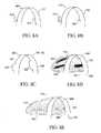
- FIGS. 4A-4Dcollectively referred to as FIG. 4, illustrate a mechanism for varying the width of a cutting loop by rotating the guide lumens around a guide axis and with respect to each other;
- FIG. 5illustrates another embodiment similar to that shown in FIG. 2, in which the tubular shaft comprises an additional window which contains a tissue capturing mechanism;
- FIGS. 6A-6Cillustrates another embodiment similar to that shown in FIG. 2, in which a tissue capturing mechanism is contained within the same primary window as the distal tips of the guide lumens;
- FIGS. 7A-7Dcollectively referred to as FIG. 7, illustrate the operation of an embodiment similar to that shown in FIG. 6;
- FIGS. 8A-8Ecollectively referred to as FIG. 8, illustrate embodiments of a tissue marker
- FIG. 9illustrates a handle that may be employed with the tissue severing device described herein;
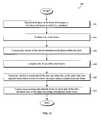
- FIG. 10is a flow chart illustrating a method to severe and remove a mass of tissue or lesion from a patient
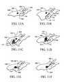
- FIGS. 11A-11Fcollectively referred to as FIG. 11, illustrate a method in which the device of FIG. 1 is used to remove a lesion from a human breast;
- FIG. 12is a flowchart illustrating a method for removing a lesion performed in relation to the internal anatomy of the breast.
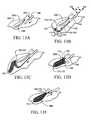
- FIGS. 13A-13Ecollectively referred to as FIG. 13, illustrate a method in which the device of FIG. 1 is used to perform a breast lobectomy.
- the present inventionrelates to devices and methods that enhance the accuracy of lesion excision, through severing, capturing and removal of a lesion within soft tissue. Furthermore, the present invention relates to devices and methods for the excision of breast tissue based on the internal anatomy of the breast gland.
- the following descriptionis presented to enable any person skilled in the art to make and use the invention. Descriptions of specific embodiments and applications are provided only as examples and various modifications will be readily apparent to those skilled in the art. The general principles defined herein may be applied to other embodiments and applications without departing from the spirit and scope of the invention. Thus, the present invention is to be accorded the widest scope encompassing numerous alternatives, modifications and equivalents consistent with the principles and features disclosed herein. For purpose of clarity, details relating to technical material that is known in the technical fields related to the invention have not been described in detail so as not to unnecessarily obscure the present invention.
- the present inventionrelates to tissue severing and removal devices as well as methods for severing and removing tissue. While the invention is generally useful for procedures in soft tissue, the devices are particularly effective in providing precise control during the excision of a lesion or abnormality in breast tissue with minimal invasiveness. In particular a method for severing and removal of part of a lobe, an entire lobe or an entire lobe plus surrounding tissue within a breast is described.
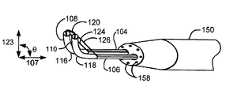
- FIG. 1illustrates the distal region of an embodiment of a tissue severing device 100 .
- the device 100includes a guide 102 comprising two co-linear, co-extensive guide lumens 104 , 106 .
- the guide lumens 104 , 106extend longitudinally from a proximal region (not shown) to a distal end 152 along a guide axis 107 , an imaginary line that lies along the longest dimension of the guide 102 .
- the guide lumens 104 , 106have co-extensive distal segments 108 , 110 terminating in distal tips 112 , 114 .
- Each distal segment 108 , 110has a deformable region 116 , 118 located in a proximal region of the corresponding distal segment 108 , 110 , respectively.
- the deformable regions 116 , 118enable each distal segment 108 , 110 to change direction with respect to the guide axis 107 .
- each distal segment 108 , 110 and the corresponding deformable regions 116 , 118 , respectively,are preferably formed as a single piece. That is, the entirety of each distal segment 108 , 110 is formed from a deformable material.
- each distal segment 108 , 110may be formed from integrating or joining separate components comprising one or more materials.
- the guide 102 containing guide lumens 104 , 106is housed in a tubular shaft 150 .
- Located at a distal end 152 of the tubular shaft 150are two openings 154 , 156 that allow the guide lumens 104 , 106 , respectively, to extend from and retract into the tubular shaft 150 .
- Any suitable mechanismmay be provided for controlling the degree to which the guide lumens 104 , 106 are extended from or retracted into the tubular shaft 150 .
- the guide lumens 104 , 106are in a retracted position such that a substantial portion of the distal segments 108 , 110 are contained within the tubular shaft 150 .
- FIG. 1Billustrates the extension of the guide lumens 104 , 106 in direction 109 until at least the deformable regions 116 , 118 are external to the tubular shaft 150 .
- the tubular shaft 150 and the guide 102are typically sufficiently rigid such that the act of penetrating the device 100 into tissue will not cause bending or deflection of either the tubular shaft 150 or the guide 102 .
- either or both the tubular shaft 150 and the guide 102may be constructed from a metallic material such as stainless steel.
- ceramic materialssuch as alumina and silica or rigid plastic materials such as polystyrene and polyester and/or any other suitable material may also be employed.
- tubular shaft 150 and the guide 102may be coated with a low friction material such as Teflon®, polyvinylidene fluoride, polyethylene, or another polymeric material to facilitate penetration of tissue by the tubular shaft 150 and the guide 102 , facilitate movement of the guide lumens 104 , 106 with respect to the tubular shaft 150 , and/or facilitate movement of the cutting tool 120 within the guide lumens 104 , 106 .
- a low friction materialsuch as Teflon®, polyvinylidene fluoride, polyethylene, or another polymeric material to facilitate penetration of tissue by the tubular shaft 150 and the guide 102 , facilitate movement of the guide lumens 104 , 106 with respect to the tubular shaft 150 , and/or facilitate movement of the cutting tool 120 within the guide lumens 104 , 106 .
- the tubular shaft 150may include one or more accessory lumens.
- accessory lumenstypically extend from lumen openings 158 located at or near the distal end 152 of the tubular shaft 150 , as illustrated in FIGS. 1 and 4.
- An accessory lumenmay comprise a transport lumen that allows a material to be transported therethrough to the distal end 152 .
- Gas, liquid, or a combination thereof from an external sourcemay be administered through the transport lumen to the distal end 152 .
- an aqueous solutionmay be employed for irrigation purposes or a local anesthetic, such as lidocaine, may be administered through the transport lumen.
- one or more of the accessory lumensmay be operatively connected to an external vacuum source.
- the external vacuum sourcemay provide suction to remove from the patient, fluids such as blood, irrigation fluid or smoke generated during use of the cutting tool 120 .
- the guide 102may be constructed to conform to the preferred characteristics of the tubular shaft 150 .
- FIG. 2Another embodiment of the guide 102 housed in the tubular shaft 150 is illustrated in FIG. 2 .
- the distal end 152 of the tubular shaft 150contains a tissue penetrant 162 that facilitates advancement of the device 100 into tissue.
- the tissue penetrant 162may be configured to a sharp point (as shown in FIG. 2 ), a trocar, a scalpel-like blade, or any other suitable mechanism.
- the tissue penetrant 162may be operatively connected to an external energy source (not shown). While the external energy source may employ thermal, ultrasonic, or any other suitable energy, the energy source is preferably a radio frequency energy source. Using a radio frequency energy source, the tissue penetrant 162 may function as a component of a monopolar or a bipolar system.
- a primary window 160is located near the distal end 152 of the tubular shaft 150 .
- the distal tips 112 , 114are aligned with the primary window 160 .
- the direction of the distal segments 108 , 110 with respect to the guide axis 107may be predetermined or may be varied as illustrated in FIG. 1 .
- a window cover 166may be used to cover and uncover the primary window 160 .
- tissue penetrationit is advantageous to prevent tissue from becoming entrapped in the primary window 160 as this may interfere with the function of the guide 102 or of the cutting tool 120 .
- the window cover 166may initially cover the primary window 160 to create a smooth, tapered shape to the tubular shaft 150 during tissue penetration.
- a window controllerPrior to extension of the cutting tool 120 to create a cutting loop (not shown), a window controller (not shown) may be used to slide the window cover 166 in the proximal direction 168 to expose the primary window 160 and the cutting tool 120 to the tissue. Similarly, the window cover 166 may slide back to its original position to cover the primary window 160 .
- FIG. 1Bwhen the guide 102 is extended out of the distal end 152 of the tubular shaft 150 , the distal segments 108 , 110 can move with respect to the guide axis 107 .
- retraction cables 124 , 126are employed to change the direction of the distal segments 108 , 110 with respect to the guide axis 107 such that, for example, the distal segments 108 , 110 are generally in an orthogonal orientation with respect to the guide axis 107 .
- the retraction cables 124 , 126serves to position the cutting loop 122 so as to vary the angle ⁇ between a loop extension axis 123 and the guide axis 107 , resulting in repositioning of the cutting loop 122 with respect to the guide axis 107 .
- the retraction cables 124 , 126may be housed within the wall of the guide lumens 104 , 106 or any other suitable control mechanism for controlling the orientation of the distal segments 108 , 110 may be employed.
- the deformable regions 116 , 118may be made of a shape-memory metal or metal alloy such as a nickel-titanium alloy.
- the deformable regions 116 , 118With the deformable regions 116 , 118 made of a shape-memory material, the deformable regions 116 , 118 deform to position distal segments 108 , 110 at a predetermined direction with respect to the guide axis 107 when the guide 102 is extended out of the distal end 152 of the tubular shaft 150 .
- the cutting loop 122can be positioned without the provision or use of retraction cables.
- the angle ⁇ between the guide axis 107 and the loop extension axis 123 when the cutting loop 122 is extendedmay alternatively be generally fixed at a predetermined angle rather than adjustable.
- the retraction cables 124 , 126may be replaced by elastic cables (not shown) that are not selectively retractable. Before the distal segments 108 , 110 are extended out of the distal end 152 of the tubular shaft 150 , the elastic cables are stretched and extended to allow the distal segments 108 , 110 to generally extend along the guide axis 107 .
- the elastic cablescontract to a predetermined length to position the distal segments 108 , 110 such that the angle ⁇ between the guide axis 107 and the loop extension axis 123 when the cutting loop 122 is extended is generally fixed at a predetermined angle.
- the deformable regions 116 , 118are made of a shape-memory material, the direction of the distal segments 108 , 110 when extended out of the distal end 152 of the tubular shaft 150 , is generally fixed.
- each distal segment 108 , 110 and the guide axis 107may be either the same or different.
- the retraction cables 124 , 126may be retracted by a same or different amount so that the distal segments 108 , 110 are in the same or different orientation relative to the guide axis 107 .
- FIG. 4illustrates a cutting loop adjuster for adjusting the width of the cutting loop 122 .
- the distal segments 108 , 110are in an orthogonal orientation with respect to the guide axis 107 .
- FIGS. 4B, 4 C and 4 Ddemonstrate that by rotating one or both of the guide lumens 104 , 106 around the guide axis 107 such that the distal tips 112 , 114 move away from each other, the cutting loop width 128 progressively increases in size until a maximal cutting loop width 128 is achieved when the distal tips 112 , 114 are facing opposite directions or an angle a is 180°.
- a generally fixed cutting loop width 128may alternatively be provided in any of the embodiments disclosed herein.
- the distal tips 112 , 114may be at a generally fixed distance relative to each other such that the cutting loop width 128 is generally fixed.
- a generally fixed cutting loop width 128may be provided where, for example, the guide lumens 104 , 106 are generally not rotatable about the guide axis 107 such that the distal tips 112 , 114 remain in a fixed distance relative to each other. It is further noted that where the cutting loop width 128 is generally fixed, the cutting loop 122 may nonetheless be extended and/or retracted as appropriate to a desired extension or loop size.
- FIG. 3illustrates another embodiment in which a tissue severing device is similar to that described above except the guide 102 comprises the guide lumen 104 that longitudinally extends along the guide axis 107 from a proximal region (not shown) to a distal segment 108 .
- the distal segment 108terminates in the distal tip 112 .
- the distal segment 108includes the deformable region 116 .
- the deformable region 116may change the direction of the distal segment 108 with respect to the guide axis 107 and thus define an angle ⁇ between the distal tip 112 and the guide axis 107 .
- the guide 102is housed in the tubular shaft 150 similar to that shown in FIG. 2, where the tubular shaft 150 has the window 160 near the distal end 152 such that the distal tip 112 of the guide 102 is aligned with the window 160 .
- the cutting tool 120is partially contained in the guide lumen 104 .
- the cutting tool 120has a fixed end 125 that may be attached to an external portion of the guide 102 , or in an alternative, as depicted in FIG. 3, the fixed end 125 may be attached to the tubular shaft 150 . In either case, the cutting tool 120 is capable of forming the cutting loop 122 extending from the distal tip 112 of the guide lumen 104 . Any suitable extension mechanism (not shown) may provide control over the degree to which the cutting loop 122 extends from the guide lumen 104 .
- the cutting loop width 128can be varied by rotating the guide 102 within the tubular shaft 150 so as to vary the distance between the distal tip 112 and the fixed end 125 .
- the distance between the distal tip 112 and the fixed end 125is generally fixed such that the cutting loop width 128 is generally fixed. It is noted that although the cutting loop width 128 is generally fixed, the cutting loop 122 may nonetheless be extended and/or retracted as appropriate to a desired extension or size.
- the direction of the distal segment 108 with respect to the guide axis 107may be varied and/or adjusted by tightening or relaxing a retraction cable (not shown) similar to that described with reference to FIG. 1 .
- the direction of the distal segment 108 with respect to the guide axis 107may be predetermined and fixed.
- FIGS. 1 and 2illustrates a preferred arrangement in which at least a portion of the cutting tool 120 is disposed in each of the guide lumens 104 , 106 .
- the cutting tool 120is capable of forming the cutting loop 122 by extending the cutting tool 120 from one or both of the distal tips 112 , 114 , as shown in FIG. 1 D.
- This extensionmay be accomplished using any suitable extension mechanism that provides control over the degree to which the cutting loop 122 extends from the guide 102 .
- such extension mechanismmay incorporate a dial on a handle 190 as illustrated in FIG. 9 or a knob (not shown) that can be pushed or pulled along the handle in the direction of the guide axis 107 , to extend and retract the cutting tool 120 , respectively, or any other mechanism known to those skilled in the art.
- the cutting tool 120may be configured in one of any number of forms to facilitate the cutting or severing of soft tissue such as breast tissue.
- the cutting tool 120may be a wire or a thin ribbon.
- the cross-sectional shape of the cutting tool 120may be round, rectangular, square, triangular or any other shape that facilitates the cutting of soft tissue.
- One or both edges of the cutting tool 120may be sharpened, serrated or both.
- the cutting tool 120may comprise a metallic material such as a metal, a metal alloy, a metal laminate, or a metal composite.
- the metallic materialmay be, for example, nickel, titanium, iron, cobalt, chromium, copper, tantalum, tungsten, and alloys thereof.
- Preferred metallic materialsinclude titanium, a titanium alloy such as a nickel-titanium alloy, and alloys such as those typically used in stainless steel.
- the cutting tool 120may be operatively connected to an external energy source 195 (as shown in FIG. 9 ).
- the external energy sourcemay be a radio frequency energy source and the cutting tool 120 comprises an electrically conductive material.
- the cutting tool 120may operate as a monopolar electrode.
- the cutting tool 120may also operate as a bipolar electrode with both electrodes located on the cutting tool 120 , itself, or with the return electrode located elsewhere on the device 100 .
- the cutting tool 120may be designed to cauterize as well as cut tissue to control excessive bleeding.
- the guide lumens 104 , 106comprise an electrically insulating material or are coated with such a material to electrically isolate the cutting tool 120 within the device 100 .
- the cutting tool 120may employ mechanical action to cut or sever tissue.
- a vibratormay be included for inducing mechanical vibration of the cutting tool 120 .
- the cutting tool 120may employ an ultrasonic energy source to cut tissue.
- Other variations relating to cutting tool design and implementationare known to those skilled in the art.
- the device 100may further include a tissue collector for collecting and removing tissue severed by the cutting tool 120 .
- the tissue collectoris preferably designed to reduce the potential spread of cancerous cells.
- the tissue collectormay comprise a collection bag with an adjustable opening that provides communication to its interior.
- the collection bagpreferably comprises an impermeable material to retain fluid and loose tissue or cells. This reduces the potential for spreading dislodged cancerous cells during removal of the collection bag from the patient.
- the collection bagis preferably thin-walled and supple. A number of plastic or polymeric materials may be used to construct the collection bag.
- These materialsinclude, but are not limited to, polyethylene, polypropylene, polybutylene, polyamide, polyimide, polyester, polyvinyl chloride, polyvinyl fluoride, polyvinylidene fluoride, polycarbonate, and polytetrafluoroethylene.
- the collection bag(not shown) may be attached to the cutting tool 120 .
- the collection bagmay open or close by increasing or decreasing the size of the cutting loop 122 , respectively.
- the severed tissueenters the collection bag as the collection bag follows the path of the cutting loop 122 .
- the collection bagis typically insulated from the cutting tool 120 .
- the collection bagmay be independently deployable with respect to the cutting loop 122 .
- a collection bag 174may be attached to a collection loop 172 that is controlled similar to the manner in which the cutting loop 122 is controlled.
- the collection loop 172extends from collection distal tips 176 , 178 of two collection lumens 180 , 182 .
- the collection loop 172is generally orthogonal to the guide axis 107 .
- the collection lumens 180 , 182are similar in design to the guide lumens 104 , 106 . As a result, the collection loop 172 may be extended, widened, narrowed, or repositioned with respect to the guide axis 107 .
- the cutting loop adjustermay also be used to adjust the collection loop 172 .
- a collection loop adjustermay be employed to control the collection loop 172 independently of the cutting loop 122 .
- the collection bag 174opens allowing severed tissue to enter and as the collection loop 172 retracts, the collection bag 174 closes trapping the severed tissue within.
- One or more points along the opening of the collection bag 174may be fixedly attached to (or adjacent to) the collection distal tip(s) 176 , 178 of the collection lumen(s) 180 , 182 and/or predetermined location(s) on the collection loop 172 .
- the remainder portion along the opening of the collection bag 174is preferably movably or slidably attached to the collection loop 172 .
- the collection loop 172is aligned with the cutting loop 122 .
- the collection lumens 180 , 182extend from the distal end 152 along direction 109 similar to the guide lumens 104 , 106 .
- the collection distal tips 176 , 178are aligned with the primary window 160 .
- the collection bag 174is contained within the tubular shaft 150 or is contained on the external surface of the tubular shaft 150 .
- FIGS. 6B and 6Cillustrate the collection loop 172 extended from the collection distal tips 176 , 178 with the collection bag 174 partially deployed as in FIG. 6 B and fully deployed as in FIG. 6 C.
- the collection distal tips 176 , 178may be aligned with an additional window 164 near the distal end 152 of the tubular shaft 150 .
- FIG. 7illustrates the device 100 in use after the cutting tool 120 has been extended to create the cutting loop 122 and the collection loop 172 has been extended to deploy the collection bag 174 .
- the cutting loop 122severs the tissue around a lesion 200 .
- the severed tissueenters the collection bag 174 as the collection bag 174 closely follows in the path created by the cutting loop 122 .
- a mass of tissue containing the lesion 200is severed and contained in the collection bag 174 .
- Retraction of the collection loop 172closes the collection bag 174 , thereby capturing the lesion 200 within the mass of tissue.
- the device 100allows tissue to be severed and collected along a straight path. If the severed tissue does not rotate or change orientation with respect to the guide axis 107 as it is removed from the patient, the surgeon or operator can carefully remove the severed tissue from the collection bag 174 without disturbing the orientation of the severed tissue. The surgeon or operator may then mark the specimen with various dyes commonly used for said purpose or with sutures or clips.
- the tissue severing devicemay further comprise a tissue marker for marking in vivo the mass of tissue severed, i.e., before it is removed from the patient.
- a tissue markerillustrated in FIG. 8A, comprises a series of marking segments 302 , 304 and 306 attached to and/or extending from the cutting loop 122 .
- the marking segments 302 , 304 and 306may comprise a series of thin strands of electrically conductive wires that trail behind the cutting loop 122 as tissue is severed.
- the marking segments 302 , 304 and 306may be in electrical communication with the cutting loop 122 .
- the marking segments 302 , 304 and 306may be similarly energized. By contacting the cut surface of the severed tissue, the marking segments 302 , 304 and 306 may cause a blackening or charring of the cut surface, thereby producing different marks on the different sides of the severed tissue.
- the marking segments 302 , 304 and 306may be arranged in any fashion to orient the severed tissue, one example being illustrated in FIG. 8 A.
- the marking segments 302 , 304 and 306 and the cutting tool 120may be formed as a single component or as an alternative, the marking segments 302 , 304 and 306 may be attached to the cutting tool 120 .
- the marking segments 302 , 304 and 306may comprise a metal, a metal alloy, a metal laminate, or a metal composite.
- the marking segments 302 , 304 and 306may comprise a braided metal, a braided metal alloy, a braided metal laminate or a braided metal composite.
- the marking segmentsmay be constructed into any pattern or patterns 308 , 310 and 312 as illustrated in FIG. 8 B.
- the marking segments in any of the above alternative embodimentsare preferably designed not to contact or interfere with the tissue collector such as the collection bag 174 (shown in FIG. 8 D).
- FIG. 8Cillustrates another embodiment of a tissue marker in which tissue marking extensions 322 , 324 , and 326 are asymmetrically arranged on a trailing edge 320 of the cutting loop 122 . If an external radio frequency energy source is used to energize the cutting loop 122 , a cutting current or sinusoidal waveform can be used to sever tissue at a leading edge 328 of the cutting loop 122 .
- the extensions 322 , 324 and 326When electrical current passes through the extensions, e.g., as a result of the electrical communication between the extensions 322 , 324 and 326 and the cutting loop 122 , the enlarged surface areas of extensions 322 , 324 and 326 would create a cautery effect resulting in charring or blackening of the surface of the severed tissue in contact with the extensions 322 , 324 and 326 .
- the extensions 322 , 324 and 326can be arranged in any pattern or number along the cutting loop 122 to asymmetrically blacken or char the surface of the severed tissue.
- the extensions 322 , 324 and 326 and the cutting loop 122may be formed as a single piece, or may be formed separately and later attached to each other.
- the extensions 322 , 324 and 326may comprise a metallic material such as a metal, a metal alloy, a metal laminate, or a metal composite.
- FIG. 8Dillustrates yet a further embodiment of the tissue marker in which the collection bag 174 is attached to the collection loop 172 .
- Dyes of different colors 330 , 332 and 334are present on individual regions on an interior surface 336 of the collection bag 174 .
- dye 330may be red
- dye 332may be blue
- dye 334may be yellow.
- the dyesmay additionally or alternatively be attached to and extending from the collection loop 172 (not shown).
- the different colored dyes 330 , 332 and 334may contact and mark the severed tissue at different locations.
- one or more dye colorsmay be used in different patterns 340 , 342 and 344 on the interior surface 336 of the collection bag 174 .
- any combination of colored dye(s), size(s), and/or pattern(s)may be used to coat the interior surface 336 of the collection bag 174 .
- the tissue markermay be coated or otherwise disposed inside of a collection bag opening 350 to thereby mark the severed tissue as it passes through the collection bag opening 350 .
- the tissue markermay coat the trailing edge of the cutting tool 120 , thereby marking the tissue just as it is severed by the leading edge of the cutting tool 120 .
- the dyesmay be any suitable dye such as methylene blue, lymphazurine blue and congo red that are commonly used in clinical medicine.
- FIG. 9illustrates an exemplary handle 190 that may be provided to facilitate ease of manipulation of any tissue severing device described herein.
- the handle 190is typically provided at the proximal region of the guide or the tubular shaft (not shown) of the tissue severing device.
- the handle 190includes controls 191 , 192 , 193 , 194 that provide control of, for example, a loop extender, a width adjuster, a distal segment positioning mechanism, and a tissue collector controller, respectively.
- the handle 190may also contain a knob or dial to control the extension and retraction of the guide as well as a knob or dial to control the window cover (not shown).
- the operatormay push a knob that is in continuity with the guide 102 in a proximal direction to extend the guide from the distal end of the tubular shaft and pull the knob in a distal direction to retract the guide.
- the handle 190may also provide an interface to the external energy source 195 , an external vacuum source 196 , and/or an external fluid or gas source 197 .
- tissue severing devicefacilitates in severing and removing a mass of tissue such as a lesion from a selected region of a patient's breast.
- tissue severing deviceis preferably performed in relation to the internal anatomy of the breast and more specifically to excise part of a lobe, an entire lobe, or an entire lobe with adjacent tissue.
- the tissue severing devicemay also be used, for example, on any other soft tissue regions, including but not limited to, liver and prostate, and may be used on other areas of a human or on non-human animals.
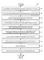
- FIG. 10illustrates a method 400 to severe and remove a mass of tissue or lesion from a patient.
- the lesion to be severed and removed from within a selected region of the patientis located.
- a tubular shaft containing a guideis inserted through an incision and into the selected region.
- the guideis similar to the guide described above with reference to FIG. 1 in which the guide includes two co-linear, co-extensive guide lumens longitudinally extending from a proximal region to a distal terminus along a guide axis, the guide lumens having co-extensive distal segments terminating in distal tips.
- the guidealso includes a cutting tool contained therein and capable of forming a cutting loop extending from the distal tips of the two guide lumens, the cutting loop forming a loop extension axis defined by the direction in which the cutting loop extends.
- the guidepreferably also includes an cutting loop extension control for controlling the degree to which the cutting loop extends from the guide.
- the angle of each distal segment of the guide lumens in relation to the guide axisis generally fixed.
- the guide lumenshave deformable regions immediately proximal to the distal segments that facilitate in changing the direction of the distal segments with respect to the guide axis.
- the guideincludes a distal segment positioning means for varying the direction of each distal segment with respect to the guide axis to thereby adjust the angle between the loop extension axis and the guide axis and selectively position the cutting loop with respect to the guide axis.
- a guidecomprises a single guide lumen that has a distal segment terminating in a distal tip.
- the guidealso includes a cutting tool that has a fixed end and is at least partially contained within the guide lumen when in a stored configuration and extendible from the distal tip thereof. Extension of the cutting tool from the guide lumen forms a cutting loop having a loop extension axis defined by the direction in which the cutting loop extends.
- the single lumen guidepreferably also includes an cutting loop extension control for controlling the degree to which the cutting loop extends from the guide and a width adjuster for selectively adjust the width of the cutting loop.
- the tubular shaft and guideare advanced into the selected region.
- the position of the distal end of the tubular shaftis evaluated in relation to the lesion at step 408 .
- the tubular shaftis repositioned by advancing and/or retracting the tubular shaft and/or by changing the angle of insertion to enable extension of the distal tips of the guide lumens to a predetermined location with respect to the lesion.
- the guide lumensare extended from the distal end of the tubular shaft to position the distal tips to the predetermined location with respect to the lesion.
- a cutting tool contained within the guideis extended from the distal tips of the two guide lumens to form a cutting loop.
- a loop extension axisis defined by the direction in which the cutting loop extends.
- the guideis moved in order to move the cutting loop along the guide axis severing tissue around the lesion.
- the cutting loopis retracted.
- the device and the severed mass of tissueare removed from the selected region through the incision.
- the method to sever and remove a mass of tissuemay optionally include a number of additional steps.
- a radiological imaging modalitymay be used to locate the lesion and visualize all or part of the procedure, including insertion of the device, severing of tissue and/or removal of the severed tissue.
- Any suitable imaging modalitymay be used, including but not limited to mammography, including digital and stereotactic mammography, MRI, including three dimensional MRI, and ultrasound, including three-dimensional ultrasound, radial or axial ductal ultrasound.
- ultrasound or three-dimensional ultrasoundis used as such imaging modalities render real-time or near real-time images.
- the cutting toolmay be operatively connected to an external energy source.
- the cutting toolmay be energized before and/or during advancement of the guide and the tubular shaft into the selected region such as in step 406 to aid in tissue penetration.
- the cutting toolmay also be energized before and/or during its extension to create a cutting loop in step 414 , during step 416 and/or during step 418 .
- the degree to which the cutting loop extends from the guide lumens, the width of the cutting loop, and/or the angle between the loop extension axis and the guide axismay optionally be varied according to the evaluation of the lesion size and the position of the distal tips of the guide lumens in relation to the lesion, after step 412 and prior to step 414 .
- the method to sever and remove a mass of tissue described abovehas the advantage of positioning a portion of the device with a larger diameter or cross-sectional area near the desired location and then extending and advancing a portion of the device with a smaller diameter or cross-sectional area for more precise and accurate positioning of the cutting tool and optionally the collection bag.
- the severed tissue or specimenmay be marked in vivo to aid in specimen orientation once the specimen is removed from the body. Such marking may occur while the tissue is being severed and/or after the tissue is severed.
- the severed tissuemay be collected while the tissue is being severed and/or after the tissue is severed. Tissue collection may be accomplished, for example, by extending a collection bag from the guide or from the tubular shaft.
- a windowmay be provided near the distal end of the tubular shaft.
- the distal tips of the guide lumensare aligned with the window allowing the cutting tool to extend and retract through the window.
- the tissueis penetrated with the tubular shaft until the distal end is proximate to the lesion.
- the distal end of the tubular shaftis preferably configured to a sharp point, trocar or scalpel-like blade.
- the distal endmay additionally or alternatively be energized by an external energy source.
- the cutting toolis extended from the distal tips of the guide lumens and through the window to create a cutting loop.
- the tubular shaftis moved along the direction of the guide axis to allow the cutting loop to sever tissue around the lesion.
- the cutting toolis retracted and the severed tissue containing the lesion is removed from the patient.
- a tubular shaft having a window near the distal endcontains a guide.
- the guidecomprises a guide lumen longitudinally extending from a proximal region to a distal terminus along a guide axis.
- the guide lumenhas a distal segment terminating in a distal tip aligned with the window.
- the guideis not housed in a tubular shaft.
- the guidecomprises two co-linear, co-extensive guide lumens longitudinally extending from a proximal region to a distal terminus along a guide axis and the guide lumens have co-extensive distal segments terminating in distal tips.
- FIG. 11illustrates the removal a lesion from within a selected region of a patient's breast utilizing one embodiment of the device described above with reference to FIG. 1 .
- FIG. 11Aillustrates the insertion of device 100 through an incision 202 located at the periareolar region of the breast 204 .
- the guide 102is advanced from distal end 152 of the tubular shaft 150 to position the distal tips 112 , 114 of the guide 102 to a predetermined position distal to the lesion 200 .
- the cutting loop 122 and the tissue collector 170are then deployed as shown in FIG. 11 C.
- the tissue collector 170comprises a tissue collection loop 172 and a tissue collection bag 174 .
- the cutting loop 122severs tissue around the lesion 200 while the collection bag 174 collects the severed mass of tissue containing the lesion 200 .
- the cutting loop 122is moved proximal to the lesion 200 , the cutting loop 122 is retracted followed by retraction of the collection loop 172 .
- retraction of the collection loop 172closes the opening of the collection bag 174 , thereby capturing the severed mass of tissue therein.
- withdrawing the entire device 100 from the breast 204results in removal of the severed mass of tissue containing the lesion 200 from the breast 204 .
- a tissue marker as described abovemay be employed as well.
- FIG. 12is a flowchart illustrating a method 450 for removing a lesion performed in relation to the internal anatomy of the breast.
- the methodbegins at step 452 in which the location of the lesion is determined with respect to the lobe of the breast in which it is contained.
- the size of the lesionis evaluated.
- the duct system of the lobeis evaluated for extension of the lesion within the ducts.
- the lobeis evaluated for possible other lesions.
- the determination to excise part of the lobe, the entire lobe, or the entire lobe plus adjacent breast tissue in order to remove the entire lesion or lesions from the breastis determined from the determinations made in steps 452 - 458 .
- a tissue severing and removal deviceis employed to excise part of the lobe, the entire lobe, or the entire lobe along with adjacent breast tissue.
- the described method involving tissue removalis based on the internal anatomical boundaries of the breast, and more particularly, excision of part of a lobe, an entire lobe or an entire lobe plus adjacent tissue, may be accomplished through surgical tools known in the art or by using the devices as described above.
- FIG. 13illustrates the use of the device of FIG. 1 to perform a breast lobectomy.
- FIG. 13Aillustrates the breast 204 of a human female patient.
- the lobe 206located within the breast 204 , contains a main duct 208 , although breast lobes may often contain more than one main duct.
- An incision 202 located at a central area of the breast 204 and preferably at the periareolar regionis usually made using an additional cutting implement such as a scalpel.
- the device 100is inserted through the incision 202 and into the breast 204 . As illustrated in FIG.
- FIG. 13Billustrates the guide 102 is advanced from the interior of the tubular shaft 150 , adjacent to the lobe 206 , to position the distal tips 112 , 114 of the guide lumens 104 , 106 past the peripheral most aspect of the lobe 206 .
- FIG. 13Billustrates the deployment of retraction cables 124 , 126 .
- the angle ⁇ between the loop extension axis 123 and the guide axis 107has been changed from approximately 180° to approximately 90°.
- the two guide lumens 104 , 106can be rotated about the guide axis 107 to move the distal tips 112 , 114 away from each other in order to widen the cutting loop 122 to allow the cutting loop 122 to encompass the width or diameter of the lobe 206 .
- FIG. 13Cillustrates extension of the cutting tool 120 to create the cutting loop 122 .
- the tissue collector 170is deployed either simultaneously with the extension of the cutting tool 120 or preferably after the cutting tool 120 has been extended and slightly moved along the guide axis 107 . This keeps the tissue collector 170 at a predetermined distance from the cutting loop 122 .
- the cutting loop 122severs the lobe 206 from surrounding tissue while the collection bag 174 of the tissue collector 170 contains the severed lobe 206 . It should be noted that the cutting loop 122 and the collection loop 172 may be adjusted while the guide is retracting to allow the severing action to follow the contour of the lobe 206 . As shown in FIG. 13E, once the cutting loop 122 has moved to a predetermined site near the nipple defining the central boundary of the lobe 206 , the cutting loop 122 is retracted followed by retraction of the collection loop 172 .
- Retraction of the collection loop 172closes the opening of the collection bag 174 , entrapping the severed lobe 206 therein.
- the severed lobe 206may be removed from the breast 204 by withdrawing the entire device 100 through the incision 202 and out of the breast 204 (not shown).
- tissue severing devicevarious other features may be provided in the tissue severing device.
- locking mechanismsmay be provided to ensure a greater degree of control over the spatial relationship between the cutting tool and the guide.
- the devicemay be manually, automatically, and/or remotely controlled.
- inventive methods and devicesmay be used on other soft tissue regions, including but not limited to liver and prostate, may be used on other areas of a human or on non-human animals as well.
Landscapes
- Health & Medical Sciences (AREA)
- Life Sciences & Earth Sciences (AREA)
- Surgery (AREA)
- Engineering & Computer Science (AREA)
- Veterinary Medicine (AREA)
- Medical Informatics (AREA)
- Molecular Biology (AREA)
- Biomedical Technology (AREA)
- Animal Behavior & Ethology (AREA)
- General Health & Medical Sciences (AREA)
- Public Health (AREA)
- Heart & Thoracic Surgery (AREA)
- Nuclear Medicine, Radiotherapy & Molecular Imaging (AREA)
- Physics & Mathematics (AREA)
- Pathology (AREA)
- Biophysics (AREA)
- Radiology & Medical Imaging (AREA)
- Hematology (AREA)
- Plasma & Fusion (AREA)
- Otolaryngology (AREA)
- Surgical Instruments (AREA)
- Processing Of Meat And Fish (AREA)
- Prostheses (AREA)
- Ultra Sonic Daignosis Equipment (AREA)
- Magnetic Resonance Imaging Apparatus (AREA)
- Control And Other Processes For Unpacking Of Materials (AREA)
Abstract
Description
Claims (64)
Priority Applications (8)
| Application Number | Priority Date | Filing Date | Title |
|---|---|---|---|
| US10/097,412US6743228B2 (en) | 2001-09-12 | 2002-03-12 | Devices and methods for tissue severing and removal |
| JP2003526289AJP2005501646A (en) | 2001-09-12 | 2002-09-10 | Apparatus and method for cutting and removing tissue |
| AU2002336487AAU2002336487A1 (en) | 2001-09-12 | 2002-09-10 | Devices and methods for tissue severing and removal |
| DE60223270TDE60223270T2 (en) | 2001-09-12 | 2002-09-10 | DEVICES FOR TISSUE SEPARATION AND REMOVAL |
| AT02773337TATE376807T1 (en) | 2001-09-12 | 2002-09-10 | DEVICES FOR TISSUE SEPARATION AND REMOVAL |
| PCT/US2002/028945WO2003022157A2 (en) | 2001-09-12 | 2002-09-10 | Devices and methods for tissue severing and removal |
| EP02773337AEP1432360B1 (en) | 2001-09-12 | 2002-09-10 | Devices for tissue severing and removal |
| US10/825,828US20040199159A1 (en) | 2001-09-12 | 2004-04-16 | Devices and methods for tissue severing and removal |
Applications Claiming Priority (2)
| Application Number | Priority Date | Filing Date | Title |
|---|---|---|---|
| US32263401P | 2001-09-12 | 2001-09-12 | |
| US10/097,412US6743228B2 (en) | 2001-09-12 | 2002-03-12 | Devices and methods for tissue severing and removal |
Related Child Applications (1)
| Application Number | Title | Priority Date | Filing Date |
|---|---|---|---|
| US10/825,828DivisionUS20040199159A1 (en) | 2001-09-12 | 2004-04-16 | Devices and methods for tissue severing and removal |
Publications (2)
| Publication Number | Publication Date |
|---|---|
| US20030163129A1 US20030163129A1 (en) | 2003-08-28 |
| US6743228B2true US6743228B2 (en) | 2004-06-01 |
Family
ID=26793229
Family Applications (2)
| Application Number | Title | Priority Date | Filing Date |
|---|---|---|---|
| US10/097,412Expired - LifetimeUS6743228B2 (en) | 2001-09-12 | 2002-03-12 | Devices and methods for tissue severing and removal |
| US10/825,828AbandonedUS20040199159A1 (en) | 2001-09-12 | 2004-04-16 | Devices and methods for tissue severing and removal |
Family Applications After (1)
| Application Number | Title | Priority Date | Filing Date |
|---|---|---|---|
| US10/825,828AbandonedUS20040199159A1 (en) | 2001-09-12 | 2004-04-16 | Devices and methods for tissue severing and removal |
Country Status (7)
| Country | Link |
|---|---|
| US (2) | US6743228B2 (en) |
| EP (1) | EP1432360B1 (en) |
| JP (1) | JP2005501646A (en) |
| AT (1) | ATE376807T1 (en) |
| AU (1) | AU2002336487A1 (en) |
| DE (1) | DE60223270T2 (en) |
| WO (1) | WO2003022157A2 (en) |
Cited By (57)
| Publication number | Priority date | Publication date | Assignee | Title |
|---|---|---|---|---|
| US20030195497A1 (en)* | 1999-04-28 | 2003-10-16 | St. Jude Medical, Inc. | Aortic heart value prosthesis sizer and marker |
| US20040072189A1 (en)* | 2000-09-20 | 2004-04-15 | Smith Arthur John | Prognostic indicator |
| US20040092957A1 (en)* | 2002-05-28 | 2004-05-13 | Lippitt Robert G. | Grasper mechanism with biased fixed flexure elements |
| US20050000525A1 (en)* | 2001-12-10 | 2005-01-06 | Klimberg V. Suzanne | Minimally invasive diagnosis and treatment for breast cancer |
| US20050113867A1 (en)* | 2003-11-25 | 2005-05-26 | Scimed Life Systems, Inc. | Forceps and collection assembly and related methods of use and manufacture |
| US20060064113A1 (en)* | 2004-09-17 | 2006-03-23 | Nakao Naomi L | Endoscopic mucosal resection method and associated instrument |
| US20060090658A1 (en)* | 2004-11-01 | 2006-05-04 | Michael Phillips | Tissue marking system |
| US20060129185A1 (en)* | 1999-10-25 | 2006-06-15 | Boston Scientific Scimed, Inc. | Forceps for medical use |
| US20060229600A1 (en)* | 2005-04-06 | 2006-10-12 | Jerome Canady | APC Dual Mode Leep Apparatus and Method |
| US20070060920A1 (en)* | 2005-08-25 | 2007-03-15 | Boston Scientific Scimed, Inc. | Endoscopic resection method |
| US20070208338A1 (en)* | 2006-03-03 | 2007-09-06 | Intact Medical Corporation | Apparatus for retrieving a tissue volume with improved positioning precursor assembly |
| US20070255303A1 (en)* | 2006-05-01 | 2007-11-01 | Ethicon Endo-Surgery, Inc. | Integrated Guidewire Needle Knife Device |
| US20070282343A1 (en)* | 2003-12-15 | 2007-12-06 | Nihon University | Bone Cutter |
| US20080015574A1 (en)* | 2006-03-31 | 2008-01-17 | Karpiel John A | Electrosurgical cutting device |
| US20080045945A1 (en)* | 2006-08-21 | 2008-02-21 | Jacques Hamou | Device For Resection And/Or Ablation Of Organic Tissue By Means Of High-Frequency Current And Resectoscope |
| US20080077130A1 (en)* | 2006-09-25 | 2008-03-27 | Pentax Corporation | High Frequency Incision Tool For Endoscope |
| USD565743S1 (en) | 2007-04-12 | 2008-04-01 | Vector Surgical, Inc. | Surgical container with applicators |
| US20080125782A1 (en)* | 2006-11-29 | 2008-05-29 | Disc Dynamics, Inc. | Method and apparatus for removing an extension from a prosthesis |
| WO2007078680A3 (en)* | 2005-12-21 | 2008-12-31 | Manoa Medical Inc | Tissue cutting device |
| US20090069806A1 (en)* | 2005-05-11 | 2009-03-12 | Mayo Foundation For Medical And Research | Apparatus and methods for internal surgical procedures |
| US7588545B2 (en) | 2003-09-10 | 2009-09-15 | Boston Scientific Scimed, Inc. | Forceps and collection assembly with accompanying mechanisms and related methods of use |
| US20100042107A1 (en)* | 2008-08-14 | 2010-02-18 | Wilson-Cook Medical Inc. | Apparatus and methods for retrieving an object from a body passage |
| US20100106052A1 (en)* | 2008-10-23 | 2010-04-29 | Margaret Uznanski | Surgical retractor |
| US7762960B2 (en) | 2005-05-13 | 2010-07-27 | Boston Scientific Scimed, Inc. | Biopsy forceps assemblies |
| US20110125145A1 (en)* | 2006-03-17 | 2011-05-26 | Microcube, Llc | Devices and methods for creating continuous lesions |
| US20120172662A1 (en)* | 2010-12-30 | 2012-07-05 | Boston Scientific Scimed, Inc. | Snare with Retractable Engaging Members |
| US8298243B2 (en) | 2007-07-30 | 2012-10-30 | Tyco Healthcare Group Lp | Combination wire electrode and tube electrode polypectomy device |
| US8328803B2 (en) | 2008-01-31 | 2012-12-11 | Covidien Lp | Polyp removal device and method of use |
| US20120323255A1 (en)* | 2004-08-12 | 2012-12-20 | Navotek Medical Ltd. | Localization of a radioactive source within a body of a subject |
| US8594768B2 (en) | 2004-11-01 | 2013-11-26 | Michael J. Phillips | Surgical system with clips for identifying the orientation of a tissue sample |
| US20150164522A1 (en)* | 2013-12-12 | 2015-06-18 | Boston Scientific Scimed, Inc. | Adjustable medical retrieval devices and related methods of use |
| US20150190190A1 (en)* | 2014-01-03 | 2015-07-09 | Boston Scientific Scimed, Inc. | Electrosurgery devices and methods for providing electric energy treatment |
| US20150327878A1 (en)* | 2014-05-15 | 2015-11-19 | Boston Scientific Scimed, Inc. | Retrieval devices and related methods of use |
| US9204888B2 (en) | 2007-06-08 | 2015-12-08 | United States Endoscopy Group, Inc. | Retrieval device |
| US9486188B2 (en) | 2001-05-18 | 2016-11-08 | United States Endoscopy Group, Inc. | Retrieval device |
| US9572591B2 (en) | 2013-09-03 | 2017-02-21 | United States Endoscopy Group, Inc. | Endoscopic snare device |
| US9731113B2 (en) | 2014-12-30 | 2017-08-15 | The Spectranetics Corporation | Collapsing coil coupling for lead extension and extraction |
| US9872700B2 (en) | 2013-09-03 | 2018-01-23 | United States Endoscopy Group, Inc. | Endoscopic snare device |
| US9884184B2 (en) | 2014-12-30 | 2018-02-06 | The Spectranetics Corporation | Wire hook coupling for lead extension and extraction |
| US9918729B2 (en) | 2009-09-14 | 2018-03-20 | The Spectranetics Corporation | Snaring systems and methods |
| US10105533B2 (en) | 2014-12-30 | 2018-10-23 | The Spectranetics Corporation | Multi-loop coupling for lead extension and extraction |
| US10117661B2 (en) | 2014-05-30 | 2018-11-06 | Cook Medical Technologies Llc | Stone extracting medical device with better stone retention |
| US10363087B2 (en) | 2009-10-12 | 2019-07-30 | Apollo Endosurgery Us, Inc. | Tissue resection device |
| US10441462B1 (en)* | 2018-05-03 | 2019-10-15 | Richard Mackool | Ophthalmic surgical instruments and methods of use thereof |
| US10463535B2 (en) | 2014-09-17 | 2019-11-05 | Carl Zeiss Meditec Cataract Technology Inc. | Devices and methods for the removal of lenticular tissue |
| US10478334B2 (en) | 2014-09-17 | 2019-11-19 | Carl Zeiss Meditec Cataract Technology Inc. | Devices and methods for cutting lenticular tissue |
| US10485700B1 (en) | 2019-06-24 | 2019-11-26 | Richard Mackool | Ophthalmic surgical instruments and snares thereof |
| US10639195B1 (en) | 2019-08-19 | 2020-05-05 | Richard Mackool | Capsular retractors |
| US10667838B2 (en) | 2017-01-09 | 2020-06-02 | United States Endoscopy Group, Inc. | Endoscopic snare device |
| US10813685B2 (en) | 2014-09-25 | 2020-10-27 | Covidien Lp | Single-handed operable surgical instrument including loop electrode with integrated pad electrode |
| US10820825B2 (en) | 2008-10-22 | 2020-11-03 | Cornell University | Method and device for evaluation of local tissue's biological or biomechanical character |
| US10932951B2 (en) | 2017-12-14 | 2021-03-02 | Carl Zeiss Meditec Cataract Technology Inc. | Devices and methods for ocular surgery |
| US11007079B1 (en) | 2019-12-02 | 2021-05-18 | Richard Mackool | Ophthalmic surgical instruments and snares thereof |
| US11357977B2 (en) | 2014-12-30 | 2022-06-14 | Spectranetics Llc | Expanding coil coupling for lead extension and extraction |
| US11413188B2 (en) | 2016-10-26 | 2022-08-16 | Carl Zeiss Meditec Cataract Technology Inc. | Devices and methods for cutting a lens in an eye |
| US11723802B2 (en) | 2016-01-30 | 2023-08-15 | Carl Zeiss Meditec Cataract Technology Inc. | Devices and methods for ocular surgery |
| US11779397B2 (en) | 2019-05-08 | 2023-10-10 | Atricure, Inc. | Biological tissue position location and marking |
Families Citing this family (133)
| Publication number | Priority date | Publication date | Assignee | Title |
|---|---|---|---|---|
| US7041101B2 (en)* | 1999-12-27 | 2006-05-09 | Neothermia Corporation | Electrosurgical accessing of tissue with controlled collateral thermal phenomena |
| AU2003297459A1 (en)* | 2002-12-20 | 2004-07-22 | Manoa Medical, Inc. | Systems and methods for cutting tissue |
| JP2006518646A (en)* | 2003-02-20 | 2006-08-17 | マノア メディカル, インコーポレイテッド | Bendable cutting device |
| US7122011B2 (en)* | 2003-06-18 | 2006-10-17 | Rubicor Medical, Inc. | Methods and devices for cutting and collecting soft tissue |
| DE10328329A1 (en)* | 2003-06-24 | 2005-01-27 | Fraunhofer-Gesellschaft zur Förderung der angewandten Forschung e.V. | Surgical device in particular to be used for removal of lung tissue, comprising loop-shaped electrodes and receptacle |
| US20050228403A1 (en)* | 2004-03-31 | 2005-10-13 | Manoa Medical, Inc., A Delaware Corporation | Tissue cutting devices and methods |
| US7118569B2 (en)* | 2004-05-03 | 2006-10-10 | Acmi Corporation | Bipolar resectoscope electrode |
| EP1750607A2 (en)* | 2004-06-02 | 2007-02-14 | Medtronic, Inc. | Loop ablation apparatus and method |
| US9101386B2 (en) | 2004-10-15 | 2015-08-11 | Amendia, Inc. | Devices and methods for treating tissue |
| US7887538B2 (en) | 2005-10-15 | 2011-02-15 | Baxano, Inc. | Methods and apparatus for tissue modification |
| US8613745B2 (en) | 2004-10-15 | 2013-12-24 | Baxano Surgical, Inc. | Methods, systems and devices for carpal tunnel release |
| US8048080B2 (en) | 2004-10-15 | 2011-11-01 | Baxano, Inc. | Flexible tissue rasp |
| US8062300B2 (en) | 2006-05-04 | 2011-11-22 | Baxano, Inc. | Tissue removal with at least partially flexible devices |
| US7959577B2 (en) | 2007-09-06 | 2011-06-14 | Baxano, Inc. | Method, system, and apparatus for neural localization |
| US8430881B2 (en) | 2004-10-15 | 2013-04-30 | Baxano, Inc. | Mechanical tissue modification devices and methods |
| US8257356B2 (en) | 2004-10-15 | 2012-09-04 | Baxano, Inc. | Guidewire exchange systems to treat spinal stenosis |
| US9247952B2 (en) | 2004-10-15 | 2016-02-02 | Amendia, Inc. | Devices and methods for tissue access |
| US7963915B2 (en) | 2004-10-15 | 2011-06-21 | Baxano, Inc. | Devices and methods for tissue access |
| US7857813B2 (en) | 2006-08-29 | 2010-12-28 | Baxano, Inc. | Tissue access guidewire system and method |
| US7578819B2 (en) | 2005-05-16 | 2009-08-25 | Baxano, Inc. | Spinal access and neural localization |
| US20110190772A1 (en) | 2004-10-15 | 2011-08-04 | Vahid Saadat | Powered tissue modification devices and methods |
| US8221397B2 (en) | 2004-10-15 | 2012-07-17 | Baxano, Inc. | Devices and methods for tissue modification |
| US20100331883A1 (en) | 2004-10-15 | 2010-12-30 | Schmitz Gregory P | Access and tissue modification systems and methods |
| US7938830B2 (en) | 2004-10-15 | 2011-05-10 | Baxano, Inc. | Powered tissue modification devices and methods |
| JP5243034B2 (en) | 2004-10-15 | 2013-07-24 | バクサノ,インク. | Tissue removal device |
| US20160001064A1 (en) | 2005-07-22 | 2016-01-07 | The Spectranetics Corporation | Endocardial lead cutting apparatus |
| US8097012B2 (en) | 2005-07-27 | 2012-01-17 | The Spectranetics Corporation | Endocardial lead removing apparatus |
| US7993359B1 (en) | 2005-07-27 | 2011-08-09 | The Spectrametics Corporation | Endocardial lead removing apparatus |
| US7591817B2 (en)* | 2005-10-11 | 2009-09-22 | Northshore University Healthsystem Research Institute | Surgical instrument for tissue resection and dissection |
| US8366712B2 (en) | 2005-10-15 | 2013-02-05 | Baxano, Inc. | Multiple pathways for spinal nerve root decompression from a single access point |
| US8062298B2 (en) | 2005-10-15 | 2011-11-22 | Baxano, Inc. | Flexible tissue removal devices and methods |
| US8092456B2 (en) | 2005-10-15 | 2012-01-10 | Baxano, Inc. | Multiple pathways for spinal nerve root decompression from a single access point |
| WO2007088533A2 (en)* | 2006-01-31 | 2007-08-09 | Roei Medical Technologies Ltd | Cutting wire electrode |
| US20070255278A1 (en)* | 2006-04-28 | 2007-11-01 | Nobis Rudolph H | Apparatus and method for deploying a cutting element during an endoscopic mucosal resection |
| AU2007201675B2 (en)* | 2006-05-01 | 2012-05-24 | Ethicon Endo-Surgery, Inc. | Dual-bend sphinctertome |
| US7655004B2 (en) | 2007-02-15 | 2010-02-02 | Ethicon Endo-Surgery, Inc. | Electroporation ablation apparatus, system, and method |
| WO2008136005A2 (en)* | 2007-05-07 | 2008-11-13 | Medi-Tate | Device for dilating the urethra of the body of a patient and device for removing prostate tissue |
| US8579897B2 (en) | 2007-11-21 | 2013-11-12 | Ethicon Endo-Surgery, Inc. | Bipolar forceps |
| US20090112059A1 (en) | 2007-10-31 | 2009-04-30 | Nobis Rudolph H | Apparatus and methods for closing a gastrotomy |
| US8480657B2 (en) | 2007-10-31 | 2013-07-09 | Ethicon Endo-Surgery, Inc. | Detachable distal overtube section and methods for forming a sealable opening in the wall of an organ |
| US8192436B2 (en) | 2007-12-07 | 2012-06-05 | Baxano, Inc. | Tissue modification devices |
| US8147488B2 (en) | 2007-12-28 | 2012-04-03 | Olympus Medical Systems Corp. | Surgical operating apparatus |
| EP2078497B8 (en)* | 2008-01-10 | 2012-03-28 | A.M.I. Agency for Medical Innovations GmbH | Medical instrument |
| US10245098B2 (en) | 2008-04-29 | 2019-04-02 | Virginia Tech Intellectual Properties, Inc. | Acute blood-brain barrier disruption using electrical energy based therapy |
| US10272178B2 (en) | 2008-04-29 | 2019-04-30 | Virginia Tech Intellectual Properties Inc. | Methods for blood-brain barrier disruption using electrical energy |
| US11254926B2 (en) | 2008-04-29 | 2022-02-22 | Virginia Tech Intellectual Properties, Inc. | Devices and methods for high frequency electroporation |
| US9598691B2 (en) | 2008-04-29 | 2017-03-21 | Virginia Tech Intellectual Properties, Inc. | Irreversible electroporation to create tissue scaffolds |
| US9867652B2 (en) | 2008-04-29 | 2018-01-16 | Virginia Tech Intellectual Properties, Inc. | Irreversible electroporation using tissue vasculature to treat aberrant cell masses or create tissue scaffolds |
| US9198733B2 (en) | 2008-04-29 | 2015-12-01 | Virginia Tech Intellectual Properties, Inc. | Treatment planning for electroporation-based therapies |
| US10238447B2 (en) | 2008-04-29 | 2019-03-26 | Virginia Tech Intellectual Properties, Inc. | System and method for ablating a tissue site by electroporation with real-time monitoring of treatment progress |
| US9283051B2 (en) | 2008-04-29 | 2016-03-15 | Virginia Tech Intellectual Properties, Inc. | System and method for estimating a treatment volume for administering electrical-energy based therapies |
| US11272979B2 (en) | 2008-04-29 | 2022-03-15 | Virginia Tech Intellectual Properties, Inc. | System and method for estimating tissue heating of a target ablation zone for electrical-energy based therapies |
| US8992517B2 (en) | 2008-04-29 | 2015-03-31 | Virginia Tech Intellectual Properties Inc. | Irreversible electroporation to treat aberrant cell masses |
| US10117707B2 (en) | 2008-04-29 | 2018-11-06 | Virginia Tech Intellectual Properties, Inc. | System and method for estimating tissue heating of a target ablation zone for electrical-energy based therapies |
| US10702326B2 (en) | 2011-07-15 | 2020-07-07 | Virginia Tech Intellectual Properties, Inc. | Device and method for electroporation based treatment of stenosis of a tubular body part |
| US8771260B2 (en) | 2008-05-30 | 2014-07-08 | Ethicon Endo-Surgery, Inc. | Actuating and articulating surgical device |
| US8679003B2 (en) | 2008-05-30 | 2014-03-25 | Ethicon Endo-Surgery, Inc. | Surgical device and endoscope including same |
| US8906035B2 (en) | 2008-06-04 | 2014-12-09 | Ethicon Endo-Surgery, Inc. | Endoscopic drop off bag |
| US8403926B2 (en) | 2008-06-05 | 2013-03-26 | Ethicon Endo-Surgery, Inc. | Manually articulating devices |
| US8048100B2 (en)* | 2008-06-10 | 2011-11-01 | Terumo Cardiovascular Systems, Corp. | Blunt dissector for separating blood vessels from surrounding tissue |
| US8361112B2 (en)* | 2008-06-27 | 2013-01-29 | Ethicon Endo-Surgery, Inc. | Surgical suture arrangement |
| US9314253B2 (en) | 2008-07-01 | 2016-04-19 | Amendia, Inc. | Tissue modification devices and methods |
| US8409206B2 (en) | 2008-07-01 | 2013-04-02 | Baxano, Inc. | Tissue modification devices and methods |
| US8398641B2 (en) | 2008-07-01 | 2013-03-19 | Baxano, Inc. | Tissue modification devices and methods |
| US8888792B2 (en) | 2008-07-14 | 2014-11-18 | Ethicon Endo-Surgery, Inc. | Tissue apposition clip application devices and methods |
| AU2009271047B2 (en)* | 2008-07-14 | 2014-04-17 | Baxano Surgical, Inc. | Tissue modification devices |
| US8409200B2 (en) | 2008-09-03 | 2013-04-02 | Ethicon Endo-Surgery, Inc. | Surgical grasping device |
| US8157834B2 (en) | 2008-11-25 | 2012-04-17 | Ethicon Endo-Surgery, Inc. | Rotational coupling device for surgical instrument with flexible actuators |
| US8361066B2 (en) | 2009-01-12 | 2013-01-29 | Ethicon Endo-Surgery, Inc. | Electrical ablation devices |
| US8753335B2 (en)* | 2009-01-23 | 2014-06-17 | Angiodynamics, Inc. | Therapeutic energy delivery device with rotational mechanism |
| EP2405823A4 (en) | 2009-03-13 | 2012-07-04 | Baxano Inc | Flexible neural localization devices and methods |
| US8632534B2 (en) | 2009-04-03 | 2014-01-21 | Angiodynamics, Inc. | Irreversible electroporation (IRE) for congestive obstructive pulmonary disease (COPD) |
| US11638603B2 (en) | 2009-04-09 | 2023-05-02 | Virginia Tech Intellectual Properties, Inc. | Selective modulation of intracellular effects of cells using pulsed electric fields |
| US11382681B2 (en) | 2009-04-09 | 2022-07-12 | Virginia Tech Intellectual Properties, Inc. | Device and methods for delivery of high frequency electrical pulses for non-thermal ablation |
| US20100268224A1 (en)* | 2009-04-17 | 2010-10-21 | Trevor Landon | Bipolar electrosurgical tool with active and return electrodes shaped to foster diffuse current flow in the tissue adjacent the return electrode |
| WO2010138919A2 (en) | 2009-05-28 | 2010-12-02 | Angiodynamics, Inc. | System and method for synchronizing energy delivery to the cardiac rhythm |
| US9895189B2 (en) | 2009-06-19 | 2018-02-20 | Angiodynamics, Inc. | Methods of sterilization and treating infection using irreversible electroporation |
| US8394102B2 (en) | 2009-06-25 | 2013-03-12 | Baxano, Inc. | Surgical tools for treatment of spinal stenosis |
| US20110098704A1 (en)* | 2009-10-28 | 2011-04-28 | Ethicon Endo-Surgery, Inc. | Electrical ablation devices |
| US8608652B2 (en) | 2009-11-05 | 2013-12-17 | Ethicon Endo-Surgery, Inc. | Vaginal entry surgical devices, kit, system, and method |
| GB2475722B (en)* | 2009-11-30 | 2011-11-02 | Mirada Medical | Measurement system for medical images |
| US8353487B2 (en) | 2009-12-17 | 2013-01-15 | Ethicon Endo-Surgery, Inc. | User interface support devices for endoscopic surgical instruments |
| US8496574B2 (en) | 2009-12-17 | 2013-07-30 | Ethicon Endo-Surgery, Inc. | Selectively positionable camera for surgical guide tube assembly |
| US8506564B2 (en) | 2009-12-18 | 2013-08-13 | Ethicon Endo-Surgery, Inc. | Surgical instrument comprising an electrode |
| US9028483B2 (en) | 2009-12-18 | 2015-05-12 | Ethicon Endo-Surgery, Inc. | Surgical instrument comprising an electrode |
| US9005198B2 (en) | 2010-01-29 | 2015-04-14 | Ethicon Endo-Surgery, Inc. | Surgical instrument comprising an electrode |
| EP2627274B1 (en) | 2010-10-13 | 2022-12-14 | AngioDynamics, Inc. | System for electrically ablating tissue of a patient |
| WO2012088149A2 (en) | 2010-12-20 | 2012-06-28 | Virginia Tech Intellectual Properties, Inc. | High-frequency electroporation for cancer therapy |
| US10092291B2 (en) | 2011-01-25 | 2018-10-09 | Ethicon Endo-Surgery, Inc. | Surgical instrument with selectively rigidizable features |
| US9254169B2 (en) | 2011-02-28 | 2016-02-09 | Ethicon Endo-Surgery, Inc. | Electrical ablation devices and methods |
| US9314620B2 (en) | 2011-02-28 | 2016-04-19 | Ethicon Endo-Surgery, Inc. | Electrical ablation devices and methods |
| US9233241B2 (en) | 2011-02-28 | 2016-01-12 | Ethicon Endo-Surgery, Inc. | Electrical ablation devices and methods |
| US9049987B2 (en) | 2011-03-17 | 2015-06-09 | Ethicon Endo-Surgery, Inc. | Hand held surgical device for manipulating an internal magnet assembly within a patient |
| US9078665B2 (en) | 2011-09-28 | 2015-07-14 | Angiodynamics, Inc. | Multiple treatment zone ablation probe |
| US10039597B2 (en)* | 2011-10-31 | 2018-08-07 | Boston Scientific Scimed, Inc. | Surgical cutting instrument and related methods |
| US9414881B2 (en) | 2012-02-08 | 2016-08-16 | Angiodynamics, Inc. | System and method for increasing a target zone for electrical ablation |
| US9463059B2 (en)* | 2012-02-09 | 2016-10-11 | Boston Scientific Scimed, Inc. | Cutting tool with circulating wire |
| US9381033B2 (en)* | 2012-04-30 | 2016-07-05 | Joseph Guo | Method and apparatus for thread transection of a ligament |
| US20130296876A1 (en)* | 2012-05-03 | 2013-11-07 | Carl Rea Jordan | Cystotome device |
| US9427255B2 (en) | 2012-05-14 | 2016-08-30 | Ethicon Endo-Surgery, Inc. | Apparatus for introducing a steerable camera assembly into a patient |
| US9078662B2 (en) | 2012-07-03 | 2015-07-14 | Ethicon Endo-Surgery, Inc. | Endoscopic cap electrode and method for using the same |
| US9545290B2 (en) | 2012-07-30 | 2017-01-17 | Ethicon Endo-Surgery, Inc. | Needle probe guide |
| US10314649B2 (en) | 2012-08-02 | 2019-06-11 | Ethicon Endo-Surgery, Inc. | Flexible expandable electrode and method of intraluminal delivery of pulsed power |
| US9572623B2 (en) | 2012-08-02 | 2017-02-21 | Ethicon Endo-Surgery, Inc. | Reusable electrode and disposable sheath |
| US9277957B2 (en) | 2012-08-15 | 2016-03-08 | Ethicon Endo-Surgery, Inc. | Electrosurgical devices and methods |
| US9308008B2 (en) | 2012-12-21 | 2016-04-12 | Cook Medical Technologies Llc | Surgical bag device and remote operating mechanism |
| US10098527B2 (en) | 2013-02-27 | 2018-10-16 | Ethidcon Endo-Surgery, Inc. | System for performing a minimally invasive surgical procedure |
| US9642645B2 (en)* | 2013-03-13 | 2017-05-09 | Boston Scientific Scimed, Inc. | Tissue cutting devices and methods |
| CN105611882B (en) | 2013-08-07 | 2018-06-26 | 史赛克公司 | Systems and methods for driving an ultrasonic handpiece as a function of mechanical impedance of the handpiece |
| US10426496B2 (en)* | 2013-08-15 | 2019-10-01 | Thomas Gaiselmann | Method for surgically removing a tumor from a woman's breast |
| WO2015175570A1 (en) | 2014-05-12 | 2015-11-19 | Virginia Tech Intellectual Properties, Inc. | Selective modulation of intracellular effects of cells using pulsed electric fields |
| US12114911B2 (en) | 2014-08-28 | 2024-10-15 | Angiodynamics, Inc. | System and method for ablating a tissue site by electroporation with real-time pulse monitoring |
| US10694972B2 (en) | 2014-12-15 | 2020-06-30 | Virginia Tech Intellectual Properties, Inc. | Devices, systems, and methods for real-time monitoring of electrophysical effects during tissue treatment |
| DE102015119427A1 (en)* | 2015-10-29 | 2017-05-04 | Bowa Electronic Gmbh & Co. Kg | Device for receiving a preparation in a retrieval bag |
| AU2017232627B2 (en)* | 2016-03-17 | 2021-07-29 | Carl Zeiss Meditec Cataract Technology Inc. | Devices and methods for cutting lenticular tissue |
| GB201608910D0 (en)* | 2016-05-20 | 2016-07-06 | Gyrus Medical Ltd | Tissue bag and method of removing excised tissue |
| US10905492B2 (en) | 2016-11-17 | 2021-02-02 | Angiodynamics, Inc. | Techniques for irreversible electroporation using a single-pole tine-style internal device communicating with an external surface electrode |
| JP6855286B2 (en)* | 2017-03-07 | 2021-04-07 | テルモ株式会社 | Medical devices and systems |
| US11357484B2 (en)* | 2017-03-30 | 2022-06-14 | Medtronic, Inc. | Medical device retrieval with multiple snares |
| US11607537B2 (en) | 2017-12-05 | 2023-03-21 | Virginia Tech Intellectual Properties, Inc. | Method for treating neurological disorders, including tumors, with electroporation |
| CN108209981A (en)* | 2018-01-02 | 2018-06-29 | 威海市妇幼保健院(威海市立第二医院、威海市妇女儿童医院) | Specimen retrieval device under a kind of laparoscope |
| US11925405B2 (en) | 2018-03-13 | 2024-03-12 | Virginia Tech Intellectual Properties, Inc. | Treatment planning system for immunotherapy enhancement via non-thermal ablation |
| US12390262B2 (en) | 2018-03-13 | 2025-08-19 | Virginia Tech Intellectual Properties, Inc. | Treatment planning system for immunotherapy enhancement via non-thermal ablation |
| US11311329B2 (en) | 2018-03-13 | 2022-04-26 | Virginia Tech Intellectual Properties, Inc. | Treatment planning for immunotherapy based treatments using non-thermal ablation techniques |
| WO2019212864A1 (en)* | 2018-05-03 | 2019-11-07 | New World Medical, Inc. | Apparatus and method for cataract extraction |
| US11950835B2 (en) | 2019-06-28 | 2024-04-09 | Virginia Tech Intellectual Properties, Inc. | Cycled pulsing to mitigate thermal damage for multi-electrode irreversible electroporation therapy |
| US12214189B2 (en) | 2019-07-24 | 2025-02-04 | Virginia Tech Intellectual Properties, Inc. | Fourier analysis spectroscopy for monitoring tissue impedance changes and treatment outcome during electroporation-based-therapies |
| CN111419186B (en)* | 2020-04-13 | 2023-04-28 | 李东 | Tool for measuring radial erection hardness of penis |
| KR102416005B1 (en)* | 2020-04-29 | 2022-06-30 | 연세대학교 산학협력단 | Apparatus and Method for Cutting and Retrieving Breast Specimen |
| US20220354515A1 (en)* | 2021-05-07 | 2022-11-10 | EndoscopyTools, LLC. | Endoscopic side snare tools and methods for use |
| CN114010240B (en)* | 2021-11-12 | 2024-05-07 | 厦门伟景医疗科技有限公司 | Sampling device for gastroenteroscope |
| EP4349288A1 (en) | 2022-10-07 | 2024-04-10 | Erbe Elektromedizin GmbH | Ablation probe with internal cooling |
| CN116269532B (en)* | 2023-05-23 | 2023-08-18 | 武汉金柏威光电技术有限公司 | Quick-cutting mammary gland biopsy excision blood coagulation device |
Citations (90)
| Publication number | Priority date | Publication date | Assignee | Title |
|---|---|---|---|---|
| DE227501C (en) | ||||
| US359506A (en) | 1887-03-15 | David h | ||
| US1741740A (en) | 1928-03-19 | 1929-12-31 | John E Sederholm | Urethro-cystoscopic instrument |
| US1967015A (en) | 1931-12-19 | 1934-07-17 | Wappler Frederick Charles | Surgical electrode |
| US2018335A (en) | 1933-08-16 | 1935-10-22 | Wappler Frederick Charles | Endoscopic instrument |
| US2047535A (en) | 1932-10-07 | 1936-07-14 | Frederick C Wappler | Surgical electrodes |
| US2447169A (en) | 1945-01-16 | 1948-08-17 | Sousa Eugenio De | Surgical instrument and technique |
| US2484059A (en) | 1945-07-10 | 1949-10-11 | American Cystoscope Makers Inc | Electrosurgical resecting instrument |
| US2545865A (en) | 1948-05-11 | 1951-03-20 | American Cystoscope Makers Inc | Electrosurgical instrument |
| US2729210A (en) | 1954-06-22 | 1956-01-03 | Frank C Spencer | Medical instrument |
| US2730101A (en) | 1954-02-23 | 1956-01-10 | Roy D Hoffman | Teat bistoury with expansible cutter knives |
| US3149633A (en) | 1961-06-15 | 1964-09-22 | Frank G Zingale | Resectoscope |
| US3320957A (en) | 1964-05-21 | 1967-05-23 | Sokolik Edward | Surgical instrument |
| US3495586A (en) | 1965-07-28 | 1970-02-17 | Eberhard Regenbogen | Rectoscope with spreading means |
| US3516412A (en) | 1965-08-16 | 1970-06-23 | Electro Catheter Corp | Bipolar electrode having irregularity at inserting end thereof and method of insertion |
| US3732858A (en) | 1968-09-16 | 1973-05-15 | Surgical Design Corp | Apparatus for removing blood clots, cataracts and other objects from the eye |
| US3805791A (en) | 1971-07-01 | 1974-04-23 | K Seuberth | Apparatus for the diathermic removal of growths |
| US3815604A (en) | 1972-06-19 | 1974-06-11 | Malley C O | Apparatus for intraocular surgery |
| US3903892A (en) | 1973-05-17 | 1975-09-09 | Olympus Optical Co | Forceps means for removing cellular tissue from the body cavities |
| US3910279A (en) | 1973-06-20 | 1975-10-07 | Olympus Optical Co | Electrosurgical instrument |
| US3942530A (en) | 1973-09-03 | 1976-03-09 | Akademiet For De Tekniske Videnskaber, Svejsecentralen | Prostate resectoscope having ultrasonic scanning |
| US3955578A (en) | 1974-12-23 | 1976-05-11 | Cook Inc. | Rotatable surgical snare |
| US4116198A (en) | 1975-05-15 | 1978-09-26 | Delma, Elektro Und Medizinische Apparatebaugesellschaft M.B.H. | Electro - surgical device |
| US4181131A (en) | 1977-02-28 | 1980-01-01 | Olympus Optical Co., Ltd. | High frequency electrosurgical instrument for cutting human body cavity structures |
| US4294254A (en) | 1977-12-08 | 1981-10-13 | Chamness Dale L | Surgical apparatus |
| US4325374A (en) | 1979-06-04 | 1982-04-20 | Olympus Optical Co., Ltd. | High frequency electrosurgical instrument for an endoscope |
| US4326530A (en) | 1980-03-05 | 1982-04-27 | Fleury Jr George J | Surgical snare |
| US4503855A (en) | 1981-12-31 | 1985-03-12 | Harald Maslanka | High frequency surgical snare electrode |
| US4538611A (en) | 1983-06-13 | 1985-09-03 | Kelman Charles D | Surgical instrument and method of cutting a lens of an eye |
| DE3609325A1 (en) | 1986-03-20 | 1987-09-24 | Karel Dr Med Cernovsky | Resectoscope |
| US4718419A (en) | 1985-08-05 | 1988-01-12 | Olympus Optical Co., Ltd. | Snare assembly for endoscope |
| US4724836A (en) | 1985-01-08 | 1988-02-16 | Olympus Optical Co., Ltd. | High-frequency incision tool |
| US4732150A (en) | 1984-06-14 | 1988-03-22 | Keener Jr Gerald T | Process for cataract extraction |
| US4903696A (en) | 1988-10-06 | 1990-02-27 | Everest Medical Corporation | Electrosurgical generator |
| DE3920707A1 (en) | 1989-06-24 | 1991-01-10 | Foerster Ernst | catheter with flexible end piece - which can be deflected by control wire in guide on side of catheter body |
| US5003979A (en) | 1989-02-21 | 1991-04-02 | University Of Virginia | System and method for the noninvasive identification and display of breast lesions and the like |
| US5078716A (en) | 1990-05-11 | 1992-01-07 | Doll Larry F | Electrosurgical apparatus for resecting abnormal protruding growth |
| US5083570A (en) | 1990-06-18 | 1992-01-28 | Mosby Richard A | Volumetric localization/biopsy/surgical device |
| US5133360A (en) | 1991-03-07 | 1992-07-28 | Spears Colin P | Spears retriever |
| US5152293A (en) | 1991-07-01 | 1992-10-06 | Northwestern University | Finger-mounted intraoperative imaging device |
| US5163938A (en) | 1990-07-19 | 1992-11-17 | Olympus Optical Co., Ltd. | High-frequency surgical treating device for use with endoscope |
| US5171314A (en) | 1990-07-24 | 1992-12-15 | Andrew Surgical, Inc. | Surgical snare |
| US5196011A (en) | 1990-10-15 | 1993-03-23 | Olympus Winter & Ibe Gmbh | Cutting electrode for medical resectoscope |
| US5197484A (en) | 1990-09-18 | 1993-03-30 | Peb Biopsy Corporation | Method and device for precutaneous excisional breast biopsy |
| US5201741A (en) | 1990-07-24 | 1993-04-13 | Andrew Surgical, Inc. | Surgical snare with shape memory effect wire |
| US5201732A (en) | 1992-04-09 | 1993-04-13 | Everest Medical Corporation | Bipolar sphincterotomy utilizing side-by-side parallel wires |
| US5217479A (en) | 1991-02-14 | 1993-06-08 | Linvatec Corporation | Surgical cutting instrument |
| US5224945A (en) | 1992-01-13 | 1993-07-06 | Interventional Technologies, Inc. | Compressible/expandable atherectomy cutter |
| US5224488A (en) | 1992-08-31 | 1993-07-06 | Neuffer Francis H | Biopsy needle with extendable cutting means |
| US5318564A (en) | 1992-05-01 | 1994-06-07 | Hemostatic Surgery Corporation | Bipolar surgical snare and methods of use |
| US5323768A (en) | 1991-04-22 | 1994-06-28 | Olympus Optical Co., Ltd. | Diathermic dissector with a bifurcation having substantially the same cross-sectional area as a lumen for guiding a wire |
| US5353804A (en) | 1990-09-18 | 1994-10-11 | Peb Biopsy Corporation | Method and device for percutaneous exisional breast biopsy |
| US5415656A (en) | 1993-09-28 | 1995-05-16 | American Medical Systems, Inc. | Electrosurgical apparatus |
| US5423830A (en) | 1993-07-07 | 1995-06-13 | Schneebaum; Cary W. | Polyp retrieval method and associated instrument assembly |
| US5437665A (en) | 1993-10-12 | 1995-08-01 | Munro; Malcolm G. | Electrosurgical loop electrode instrument for laparoscopic surgery |
| US5441510A (en) | 1993-09-01 | 1995-08-15 | Technology Development Center | Bi-axial cutter apparatus for catheter |
| US5486173A (en) | 1993-12-08 | 1996-01-23 | Vancaillie; Thierry G. | Self-guiding electrode and cutting tip for tissue resection |
| US5569244A (en) | 1995-04-20 | 1996-10-29 | Symbiosis Corporation | Loop electrodes for electrocautery probes for use with a resectoscope |
| US5630426A (en) | 1995-03-03 | 1997-05-20 | Neovision Corporation | Apparatus and method for characterization and treatment of tumors |
| US5672172A (en) | 1994-06-23 | 1997-09-30 | Vros Corporation | Surgical instrument with ultrasound pulse generator |
| US5681324A (en) | 1993-06-16 | 1997-10-28 | Ethicon, Inc. | Surgical tissue retrieval instrument |
| US5709697A (en) | 1995-11-22 | 1998-01-20 | United States Surgical Corporation | Apparatus and method for removing tissue |
| US5709206A (en) | 1995-11-27 | 1998-01-20 | Teboul; Michel | Imaging system for breast sonography |
| US5733283A (en) | 1996-06-05 | 1998-03-31 | Malis; Jerry L. | Flat loop bipolar electrode tips for electrosurgical instrument |
| US5795308A (en) | 1995-03-09 | 1998-08-18 | Russin; Lincoln D. | Apparatus for coaxial breast biopsy |
| EP0858774A2 (en) | 1997-01-21 | 1998-08-19 | Ethicon Endo-Surgery, Inc. | Devices for collection of soft tissue |
| US5807276A (en) | 1995-03-09 | 1998-09-15 | Russin; Lincoln David | Biopsy device and method |
| US5810806A (en) | 1996-08-29 | 1998-09-22 | Ethicon Endo-Surgery | Methods and devices for collection of soft tissue |
| WO1999004704A2 (en) | 1997-07-24 | 1999-02-04 | Mcguckin James F Jr | Breast surgery method and apparatus |
| US5895399A (en) | 1996-07-17 | 1999-04-20 | Embol-X Inc. | Atherectomy device having trapping and excising means for removal of plaque from the aorta and other arteries |
| US5906622A (en)* | 1997-04-29 | 1999-05-25 | Lippitt; Robert G. | Positively expanded and retracted medical extractor |
| US5919190A (en) | 1996-12-20 | 1999-07-06 | Vandusseldorp; Gregg A. | Cutting loop for an electrocautery probe |
| US5924175A (en) | 1997-04-29 | 1999-07-20 | Lippitt; Robert G. | Annularly expanding and retracting gripping and releasing mechanism |
| US5967984A (en) | 1995-06-30 | 1999-10-19 | Boston Scientific Corporation | Ultrasound imaging catheter with a cutting element |
| US5971994A (en) | 1997-07-16 | 1999-10-26 | Gebrueder Berchtold Gmbh | High frequency surgical instrument |
| US6007546A (en) | 1998-10-26 | 1999-12-28 | Boston Scientific Ltd. | Injection snare |
| US6015415A (en) | 1999-03-09 | 2000-01-18 | General Science And Technology | Polypectomy snare instrument |
| US6022362A (en) | 1998-09-03 | 2000-02-08 | Rubicor Medical, Inc. | Excisional biopsy devices and methods |
| US6036698A (en) | 1998-10-30 | 2000-03-14 | Vivant Medical, Inc. | Expandable ring percutaneous tissue removal device |
| US6063077A (en) | 1996-04-08 | 2000-05-16 | Cardima, Inc. | Linear ablation device and assembly |
| US6068603A (en) | 1998-02-17 | 2000-05-30 | Olympus Optical Co., Ltd. | Medical instrument for use in combination with an endoscope |
| WO2000030531A1 (en) | 1998-11-20 | 2000-06-02 | Senorx Inc. | Tissue acquisition system and method of use |
| US6071274A (en) | 1996-12-19 | 2000-06-06 | Ep Technologies, Inc. | Loop structures for supporting multiple electrode elements |
| WO2000033105A2 (en) | 1998-11-30 | 2000-06-08 | Carewise Medical Products Corporation | Minimally invasive surgical instrument for tissue identification, dislodgment and retrieval and methods of use |
| WO2000076555A1 (en) | 1999-06-11 | 2000-12-21 | Pro Duct Health, Inc. | Gel composition for filing a breast milk duct prior to surgical excision of the duct or other breast tissue |
| WO2000078221A1 (en) | 1999-06-17 | 2000-12-28 | Kai Desinger | Surgical, grooved director for collecting tissue in a minimally invasive manner |
| US6237605B1 (en)* | 1996-10-22 | 2001-05-29 | Epicor, Inc. | Methods of epicardial ablation |
| US6267759B1 (en) | 1999-06-22 | 2001-07-31 | Senorx, Inc. | Shaped scalpel |
| US6331166B1 (en) | 1998-03-03 | 2001-12-18 | Senorx, Inc. | Breast biopsy system and method |
| US6527769B2 (en)* | 1998-03-02 | 2003-03-04 | Atrionix, Inc. | Tissue ablation system and method for forming long linear lesion |
Family Cites Families (2)
| Publication number | Priority date | Publication date | Assignee | Title |
|---|---|---|---|---|
| US5085659A (en)* | 1990-11-21 | 1992-02-04 | Everest Medical Corporation | Biopsy device with bipolar coagulation capability |
| US6537273B1 (en)* | 1999-07-02 | 2003-03-25 | Alexander K. D. Sosiak | Device and method for removing large tissue masses |
- 2002
- 2002-03-12USUS10/097,412patent/US6743228B2/ennot_activeExpired - Lifetime
- 2002-09-10EPEP02773337Apatent/EP1432360B1/ennot_activeExpired - Lifetime
- 2002-09-10DEDE60223270Tpatent/DE60223270T2/ennot_activeExpired - Fee Related
- 2002-09-10JPJP2003526289Apatent/JP2005501646A/enactivePending
- 2002-09-10ATAT02773337Tpatent/ATE376807T1/ennot_activeIP Right Cessation
- 2002-09-10WOPCT/US2002/028945patent/WO2003022157A2/enactiveIP Right Grant
- 2002-09-10AUAU2002336487Apatent/AU2002336487A1/ennot_activeAbandoned
- 2004
- 2004-04-16USUS10/825,828patent/US20040199159A1/ennot_activeAbandoned
Patent Citations (92)
| Publication number | Priority date | Publication date | Assignee | Title |
|---|---|---|---|---|
| DE227501C (en) | ||||
| US359506A (en) | 1887-03-15 | David h | ||
| US1741740A (en) | 1928-03-19 | 1929-12-31 | John E Sederholm | Urethro-cystoscopic instrument |
| US1967015A (en) | 1931-12-19 | 1934-07-17 | Wappler Frederick Charles | Surgical electrode |
| US2047535A (en) | 1932-10-07 | 1936-07-14 | Frederick C Wappler | Surgical electrodes |
| US2018335A (en) | 1933-08-16 | 1935-10-22 | Wappler Frederick Charles | Endoscopic instrument |
| US2447169A (en) | 1945-01-16 | 1948-08-17 | Sousa Eugenio De | Surgical instrument and technique |
| US2484059A (en) | 1945-07-10 | 1949-10-11 | American Cystoscope Makers Inc | Electrosurgical resecting instrument |
| US2545865A (en) | 1948-05-11 | 1951-03-20 | American Cystoscope Makers Inc | Electrosurgical instrument |
| US2730101A (en) | 1954-02-23 | 1956-01-10 | Roy D Hoffman | Teat bistoury with expansible cutter knives |
| US2729210A (en) | 1954-06-22 | 1956-01-03 | Frank C Spencer | Medical instrument |
| US3149633A (en) | 1961-06-15 | 1964-09-22 | Frank G Zingale | Resectoscope |
| US3320957A (en) | 1964-05-21 | 1967-05-23 | Sokolik Edward | Surgical instrument |
| US3495586A (en) | 1965-07-28 | 1970-02-17 | Eberhard Regenbogen | Rectoscope with spreading means |
| US3516412A (en) | 1965-08-16 | 1970-06-23 | Electro Catheter Corp | Bipolar electrode having irregularity at inserting end thereof and method of insertion |
| US3732858A (en) | 1968-09-16 | 1973-05-15 | Surgical Design Corp | Apparatus for removing blood clots, cataracts and other objects from the eye |
| US3805791A (en) | 1971-07-01 | 1974-04-23 | K Seuberth | Apparatus for the diathermic removal of growths |
| US3815604A (en) | 1972-06-19 | 1974-06-11 | Malley C O | Apparatus for intraocular surgery |
| US3903892A (en) | 1973-05-17 | 1975-09-09 | Olympus Optical Co | Forceps means for removing cellular tissue from the body cavities |
| US3910279A (en) | 1973-06-20 | 1975-10-07 | Olympus Optical Co | Electrosurgical instrument |
| US3942530A (en) | 1973-09-03 | 1976-03-09 | Akademiet For De Tekniske Videnskaber, Svejsecentralen | Prostate resectoscope having ultrasonic scanning |
| US3955578A (en) | 1974-12-23 | 1976-05-11 | Cook Inc. | Rotatable surgical snare |
| US4116198A (en) | 1975-05-15 | 1978-09-26 | Delma, Elektro Und Medizinische Apparatebaugesellschaft M.B.H. | Electro - surgical device |
| US4181131A (en) | 1977-02-28 | 1980-01-01 | Olympus Optical Co., Ltd. | High frequency electrosurgical instrument for cutting human body cavity structures |
| US4294254A (en) | 1977-12-08 | 1981-10-13 | Chamness Dale L | Surgical apparatus |
| US4325374A (en) | 1979-06-04 | 1982-04-20 | Olympus Optical Co., Ltd. | High frequency electrosurgical instrument for an endoscope |
| US4326530A (en) | 1980-03-05 | 1982-04-27 | Fleury Jr George J | Surgical snare |
| US4503855A (en) | 1981-12-31 | 1985-03-12 | Harald Maslanka | High frequency surgical snare electrode |
| US4538611A (en) | 1983-06-13 | 1985-09-03 | Kelman Charles D | Surgical instrument and method of cutting a lens of an eye |
| US4732150A (en) | 1984-06-14 | 1988-03-22 | Keener Jr Gerald T | Process for cataract extraction |
| US4724836A (en) | 1985-01-08 | 1988-02-16 | Olympus Optical Co., Ltd. | High-frequency incision tool |
| US4718419A (en) | 1985-08-05 | 1988-01-12 | Olympus Optical Co., Ltd. | Snare assembly for endoscope |
| DE3609325A1 (en) | 1986-03-20 | 1987-09-24 | Karel Dr Med Cernovsky | Resectoscope |
| US4903696A (en) | 1988-10-06 | 1990-02-27 | Everest Medical Corporation | Electrosurgical generator |
| US5003979A (en) | 1989-02-21 | 1991-04-02 | University Of Virginia | System and method for the noninvasive identification and display of breast lesions and the like |
| DE3920707A1 (en) | 1989-06-24 | 1991-01-10 | Foerster Ernst | catheter with flexible end piece - which can be deflected by control wire in guide on side of catheter body |
| US5078716A (en) | 1990-05-11 | 1992-01-07 | Doll Larry F | Electrosurgical apparatus for resecting abnormal protruding growth |
| US5083570A (en) | 1990-06-18 | 1992-01-28 | Mosby Richard A | Volumetric localization/biopsy/surgical device |
| US5163938A (en) | 1990-07-19 | 1992-11-17 | Olympus Optical Co., Ltd. | High-frequency surgical treating device for use with endoscope |
| US5201741A (en) | 1990-07-24 | 1993-04-13 | Andrew Surgical, Inc. | Surgical snare with shape memory effect wire |
| US5171314A (en) | 1990-07-24 | 1992-12-15 | Andrew Surgical, Inc. | Surgical snare |
| US5197484A (en) | 1990-09-18 | 1993-03-30 | Peb Biopsy Corporation | Method and device for precutaneous excisional breast biopsy |
| US5353804A (en) | 1990-09-18 | 1994-10-11 | Peb Biopsy Corporation | Method and device for percutaneous exisional breast biopsy |
| US5196011A (en) | 1990-10-15 | 1993-03-23 | Olympus Winter & Ibe Gmbh | Cutting electrode for medical resectoscope |
| US5217479A (en) | 1991-02-14 | 1993-06-08 | Linvatec Corporation | Surgical cutting instrument |
| US5133360A (en) | 1991-03-07 | 1992-07-28 | Spears Colin P | Spears retriever |
| US5323768A (en) | 1991-04-22 | 1994-06-28 | Olympus Optical Co., Ltd. | Diathermic dissector with a bifurcation having substantially the same cross-sectional area as a lumen for guiding a wire |
| US5152293A (en) | 1991-07-01 | 1992-10-06 | Northwestern University | Finger-mounted intraoperative imaging device |
| US5224945A (en) | 1992-01-13 | 1993-07-06 | Interventional Technologies, Inc. | Compressible/expandable atherectomy cutter |
| US5201732A (en) | 1992-04-09 | 1993-04-13 | Everest Medical Corporation | Bipolar sphincterotomy utilizing side-by-side parallel wires |
| US5318564A (en) | 1992-05-01 | 1994-06-07 | Hemostatic Surgery Corporation | Bipolar surgical snare and methods of use |
| US5224488A (en) | 1992-08-31 | 1993-07-06 | Neuffer Francis H | Biopsy needle with extendable cutting means |
| US5681324A (en) | 1993-06-16 | 1997-10-28 | Ethicon, Inc. | Surgical tissue retrieval instrument |
| US5423830A (en) | 1993-07-07 | 1995-06-13 | Schneebaum; Cary W. | Polyp retrieval method and associated instrument assembly |
| US5441510A (en) | 1993-09-01 | 1995-08-15 | Technology Development Center | Bi-axial cutter apparatus for catheter |
| US5415656A (en) | 1993-09-28 | 1995-05-16 | American Medical Systems, Inc. | Electrosurgical apparatus |
| US5437665A (en) | 1993-10-12 | 1995-08-01 | Munro; Malcolm G. | Electrosurgical loop electrode instrument for laparoscopic surgery |
| US5486173A (en) | 1993-12-08 | 1996-01-23 | Vancaillie; Thierry G. | Self-guiding electrode and cutting tip for tissue resection |
| US5672172A (en) | 1994-06-23 | 1997-09-30 | Vros Corporation | Surgical instrument with ultrasound pulse generator |
| US5630426A (en) | 1995-03-03 | 1997-05-20 | Neovision Corporation | Apparatus and method for characterization and treatment of tumors |
| US5807276A (en) | 1995-03-09 | 1998-09-15 | Russin; Lincoln David | Biopsy device and method |
| US6080114A (en) | 1995-03-09 | 2000-06-27 | Russin; Lincoln D. | Method for coaxial breast biopsy |
| US5795308A (en) | 1995-03-09 | 1998-08-18 | Russin; Lincoln D. | Apparatus for coaxial breast biopsy |
| US5569244A (en) | 1995-04-20 | 1996-10-29 | Symbiosis Corporation | Loop electrodes for electrocautery probes for use with a resectoscope |
| US5967984A (en) | 1995-06-30 | 1999-10-19 | Boston Scientific Corporation | Ultrasound imaging catheter with a cutting element |
| US5709697A (en) | 1995-11-22 | 1998-01-20 | United States Surgical Corporation | Apparatus and method for removing tissue |
| US5709206A (en) | 1995-11-27 | 1998-01-20 | Teboul; Michel | Imaging system for breast sonography |
| US6063077A (en) | 1996-04-08 | 2000-05-16 | Cardima, Inc. | Linear ablation device and assembly |
| US5733283A (en) | 1996-06-05 | 1998-03-31 | Malis; Jerry L. | Flat loop bipolar electrode tips for electrosurgical instrument |
| US5895399A (en) | 1996-07-17 | 1999-04-20 | Embol-X Inc. | Atherectomy device having trapping and excising means for removal of plaque from the aorta and other arteries |
| US5810806A (en) | 1996-08-29 | 1998-09-22 | Ethicon Endo-Surgery | Methods and devices for collection of soft tissue |
| US6237605B1 (en)* | 1996-10-22 | 2001-05-29 | Epicor, Inc. | Methods of epicardial ablation |
| US6071274A (en) | 1996-12-19 | 2000-06-06 | Ep Technologies, Inc. | Loop structures for supporting multiple electrode elements |
| US5919190A (en) | 1996-12-20 | 1999-07-06 | Vandusseldorp; Gregg A. | Cutting loop for an electrocautery probe |
| US6132428A (en) | 1996-12-20 | 2000-10-17 | Vandusseldorp; Gregg A. | Cutting loop for an electrocautery probe |
| EP0858774A2 (en) | 1997-01-21 | 1998-08-19 | Ethicon Endo-Surgery, Inc. | Devices for collection of soft tissue |
| US5906622A (en)* | 1997-04-29 | 1999-05-25 | Lippitt; Robert G. | Positively expanded and retracted medical extractor |
| US5924175A (en) | 1997-04-29 | 1999-07-20 | Lippitt; Robert G. | Annularly expanding and retracting gripping and releasing mechanism |
| US5971994A (en) | 1997-07-16 | 1999-10-26 | Gebrueder Berchtold Gmbh | High frequency surgical instrument |
| WO1999004704A2 (en) | 1997-07-24 | 1999-02-04 | Mcguckin James F Jr | Breast surgery method and apparatus |
| US6068603A (en) | 1998-02-17 | 2000-05-30 | Olympus Optical Co., Ltd. | Medical instrument for use in combination with an endoscope |
| US6527769B2 (en)* | 1998-03-02 | 2003-03-04 | Atrionix, Inc. | Tissue ablation system and method for forming long linear lesion |
| US6331166B1 (en) | 1998-03-03 | 2001-12-18 | Senorx, Inc. | Breast biopsy system and method |
| US6022362A (en) | 1998-09-03 | 2000-02-08 | Rubicor Medical, Inc. | Excisional biopsy devices and methods |
| US6007546A (en) | 1998-10-26 | 1999-12-28 | Boston Scientific Ltd. | Injection snare |
| US6036698A (en) | 1998-10-30 | 2000-03-14 | Vivant Medical, Inc. | Expandable ring percutaneous tissue removal device |
| WO2000030531A1 (en) | 1998-11-20 | 2000-06-02 | Senorx Inc. | Tissue acquisition system and method of use |
| WO2000033105A2 (en) | 1998-11-30 | 2000-06-08 | Carewise Medical Products Corporation | Minimally invasive surgical instrument for tissue identification, dislodgment and retrieval and methods of use |
| US6015415A (en) | 1999-03-09 | 2000-01-18 | General Science And Technology | Polypectomy snare instrument |
| WO2000076555A1 (en) | 1999-06-11 | 2000-12-21 | Pro Duct Health, Inc. | Gel composition for filing a breast milk duct prior to surgical excision of the duct or other breast tissue |
| WO2000078221A1 (en) | 1999-06-17 | 2000-12-28 | Kai Desinger | Surgical, grooved director for collecting tissue in a minimally invasive manner |
| US6267759B1 (en) | 1999-06-22 | 2001-07-31 | Senorx, Inc. | Shaped scalpel |
Cited By (119)
| Publication number | Priority date | Publication date | Assignee | Title |
|---|---|---|---|---|
| US7338484B2 (en)* | 1999-04-28 | 2008-03-04 | St. Jude Medical, Inc. | Aortic heart valve prosthesis sizer and marker |
| US20030195497A1 (en)* | 1999-04-28 | 2003-10-16 | St. Jude Medical, Inc. | Aortic heart value prosthesis sizer and marker |
| US20060129185A1 (en)* | 1999-10-25 | 2006-06-15 | Boston Scientific Scimed, Inc. | Forceps for medical use |
| US7909850B2 (en) | 1999-10-25 | 2011-03-22 | Boston Scientific Scimed, Inc. | Forceps for medical use |
| US7118586B1 (en) | 1999-10-25 | 2006-10-10 | Boston Scientific Scimed, Inc. | Forceps for medical use |
| US20060263370A1 (en)* | 2000-09-20 | 2006-11-23 | Smith Arthur J | Prognostic indicator |
| US20040072189A1 (en)* | 2000-09-20 | 2004-04-15 | Smith Arthur John | Prognostic indicator |
| US20060263371A1 (en)* | 2000-09-20 | 2006-11-23 | Smith Arthur J | Prognostic indicator |
| US20060263383A1 (en)* | 2000-09-20 | 2006-11-23 | Smith Arthur J | Prognostic indicator |
| US10772648B2 (en) | 2001-05-18 | 2020-09-15 | United States Endoscopy Group, Inc. | Retrieval device |
| US9730716B2 (en) | 2001-05-18 | 2017-08-15 | United States Endoscopy Group, Inc. | Retrieval device |
| US9486188B2 (en) | 2001-05-18 | 2016-11-08 | United States Endoscopy Group, Inc. | Retrieval device |
| US7769432B2 (en)* | 2001-12-10 | 2010-08-03 | Board Of Trustees Of The University Of Arkansas | Minimally invasive diagnosis and treatment for breast cancer |
| US20050000525A1 (en)* | 2001-12-10 | 2005-01-06 | Klimberg V. Suzanne | Minimally invasive diagnosis and treatment for breast cancer |
| US20040092957A1 (en)* | 2002-05-28 | 2004-05-13 | Lippitt Robert G. | Grasper mechanism with biased fixed flexure elements |
| US7041108B2 (en)* | 2002-05-28 | 2006-05-09 | Lippitt Extractor Company, Llc | Grasper mechanism with biased fixed flexure elements |
| US8460205B2 (en) | 2003-09-10 | 2013-06-11 | Boston Scientific Scimed, Inc. | Forceps and collection assembly with accompanying mechanisms and related methods of use |
| US8083686B2 (en) | 2003-09-10 | 2011-12-27 | Boston Scientific Scimed, Inc. | Forceps and collection assembly with accompanying mechanisms and related methods of use |
| US7588545B2 (en) | 2003-09-10 | 2009-09-15 | Boston Scientific Scimed, Inc. | Forceps and collection assembly with accompanying mechanisms and related methods of use |
| US7942896B2 (en) | 2003-11-25 | 2011-05-17 | Scimed Life Systems, Inc. | Forceps and collection assembly and related methods of use and manufacture |
| US20050113867A1 (en)* | 2003-11-25 | 2005-05-26 | Scimed Life Systems, Inc. | Forceps and collection assembly and related methods of use and manufacture |
| US20070282343A1 (en)* | 2003-12-15 | 2007-12-06 | Nihon University | Bone Cutter |
| US20120323255A1 (en)* | 2004-08-12 | 2012-12-20 | Navotek Medical Ltd. | Localization of a radioactive source within a body of a subject |
| WO2006036326A3 (en)* | 2004-09-17 | 2007-09-07 | Granit Med Innovation Llc | Endoscopic mucosal resection method and associated instrument |
| US20060064113A1 (en)* | 2004-09-17 | 2006-03-23 | Nakao Naomi L | Endoscopic mucosal resection method and associated instrument |
| US20080028962A1 (en)* | 2004-11-01 | 2008-02-07 | Michael Phillips | Tissue marking system |
| US10238465B1 (en) | 2004-11-01 | 2019-03-26 | Vector Surgical, Llc | Tissue marking system |
| US9044268B2 (en) | 2004-11-01 | 2015-06-02 | Michael Phillips | Method of identifying the orientation of a tissue sample |
| US8750966B2 (en) | 2004-11-01 | 2014-06-10 | Michael J. Phillips | Method for marking a tissue sample |
| US10507077B2 (en) | 2004-11-01 | 2019-12-17 | Vector Surgical, Llc | Tissue marking system |
| US8594768B2 (en) | 2004-11-01 | 2013-11-26 | Michael J. Phillips | Surgical system with clips for identifying the orientation of a tissue sample |
| US20060090658A1 (en)* | 2004-11-01 | 2006-05-04 | Michael Phillips | Tissue marking system |
| US20060229600A1 (en)* | 2005-04-06 | 2006-10-12 | Jerome Canady | APC Dual Mode Leep Apparatus and Method |
| US7611510B2 (en)* | 2005-04-06 | 2009-11-03 | Jerome Canady | APC dual mode LEEP apparatus and method |
| US20090069806A1 (en)* | 2005-05-11 | 2009-03-12 | Mayo Foundation For Medical And Research | Apparatus and methods for internal surgical procedures |
| US8747403B2 (en) | 2005-05-11 | 2014-06-10 | Mayo Foundation For Medical Education And Research | Apparatus and methods for internal surgical procedures |
| US9839440B2 (en) | 2005-05-11 | 2017-12-12 | Mayo Foundation For Medical Education And Research | Apparatus and methods for internal surgical procedures |
| US8287535B2 (en)* | 2005-05-11 | 2012-10-16 | Mayo Foundation For Medical Education And Research | Apparatus and methods for internal surgical procedures |
| US7762960B2 (en) | 2005-05-13 | 2010-07-27 | Boston Scientific Scimed, Inc. | Biopsy forceps assemblies |
| US8672859B2 (en) | 2005-05-13 | 2014-03-18 | Boston Scientific Scimed, Inc. | Biopsy forceps assemblies |
| US8317726B2 (en) | 2005-05-13 | 2012-11-27 | Boston Scientific Scimed, Inc. | Biopsy forceps assemblies |
| US20070060920A1 (en)* | 2005-08-25 | 2007-03-15 | Boston Scientific Scimed, Inc. | Endoscopic resection method |
| US7789881B2 (en) | 2005-08-25 | 2010-09-07 | Boston Scientific Scimed, Inc. | Endoscopic resection method |
| US10849683B2 (en) | 2005-08-25 | 2020-12-01 | Boston Scientific Scimed, Inc. | Endoscopic resection method |
| US8100905B2 (en) | 2005-08-25 | 2012-01-24 | Boston Scientific Scimed, Inc. | Endoscopic resection method |
| US9655671B2 (en) | 2005-08-25 | 2017-05-23 | Boston Scientific Scimed, Inc. | Endoscopic resection device |
| WO2007078680A3 (en)* | 2005-12-21 | 2008-12-31 | Manoa Medical Inc | Tissue cutting device |
| US7569053B2 (en) | 2006-03-03 | 2009-08-04 | Intact Medical Corporation | Apparatus for retrieving a tissue volume with improved positioning precursor assembly |
| US20070208338A1 (en)* | 2006-03-03 | 2007-09-06 | Intact Medical Corporation | Apparatus for retrieving a tissue volume with improved positioning precursor assembly |
| US11065055B2 (en) | 2006-03-17 | 2021-07-20 | Microcube, Llc | Devices and methods for creating continuous lesions |
| US11864828B2 (en) | 2006-03-17 | 2024-01-09 | Microcube, Llc | Devices and methods for creating continuous lesions |
| US20110125145A1 (en)* | 2006-03-17 | 2011-05-26 | Microcube, Llc | Devices and methods for creating continuous lesions |
| US20080015574A1 (en)* | 2006-03-31 | 2008-01-17 | Karpiel John A | Electrosurgical cutting device |
| US20070255303A1 (en)* | 2006-05-01 | 2007-11-01 | Ethicon Endo-Surgery, Inc. | Integrated Guidewire Needle Knife Device |
| US8267933B2 (en)* | 2006-08-21 | 2012-09-18 | Jacques Hamou | Device for resection and/or ablation of organic tissue by means of high-frequency current and resectoscope |
| US20080045945A1 (en)* | 2006-08-21 | 2008-02-21 | Jacques Hamou | Device For Resection And/Or Ablation Of Organic Tissue By Means Of High-Frequency Current And Resectoscope |
| US20080077130A1 (en)* | 2006-09-25 | 2008-03-27 | Pentax Corporation | High Frequency Incision Tool For Endoscope |
| US20080125782A1 (en)* | 2006-11-29 | 2008-05-29 | Disc Dynamics, Inc. | Method and apparatus for removing an extension from a prosthesis |
| USD565743S1 (en) | 2007-04-12 | 2008-04-01 | Vector Surgical, Inc. | Surgical container with applicators |
| US9204888B2 (en) | 2007-06-08 | 2015-12-08 | United States Endoscopy Group, Inc. | Retrieval device |
| US9826997B2 (en) | 2007-06-08 | 2017-11-28 | U.S. Endoscopy Group, Inc. | Retrieval device |
| US11166735B2 (en) | 2007-06-08 | 2021-11-09 | United States Endoscopy Group, Inc. | Retrieval device |
| US8298243B2 (en) | 2007-07-30 | 2012-10-30 | Tyco Healthcare Group Lp | Combination wire electrode and tube electrode polypectomy device |
| US9918771B2 (en) | 2008-01-31 | 2018-03-20 | Covidien Lp | Polyp removal device and method of use |
| US10959767B2 (en) | 2008-01-31 | 2021-03-30 | Covidien Lp | Polyp removal device and method of use |
| US8328803B2 (en) | 2008-01-31 | 2012-12-11 | Covidien Lp | Polyp removal device and method of use |
| USRE46063E1 (en) | 2008-01-31 | 2016-07-12 | Covidien Lp | Polyp removal device and method of use |
| US20100042107A1 (en)* | 2008-08-14 | 2010-02-18 | Wilson-Cook Medical Inc. | Apparatus and methods for retrieving an object from a body passage |
| US10820825B2 (en) | 2008-10-22 | 2020-11-03 | Cornell University | Method and device for evaluation of local tissue's biological or biomechanical character |
| US20100106052A1 (en)* | 2008-10-23 | 2010-04-29 | Margaret Uznanski | Surgical retractor |
| US10687836B2 (en) | 2009-09-14 | 2020-06-23 | Spectranetics Llc | Snaring systems and methods |
| US9918729B2 (en) | 2009-09-14 | 2018-03-20 | The Spectranetics Corporation | Snaring systems and methods |
| US10363087B2 (en) | 2009-10-12 | 2019-07-30 | Apollo Endosurgery Us, Inc. | Tissue resection device |
| US9700345B2 (en)* | 2010-12-30 | 2017-07-11 | Boston Scientific Scimed, Inc. | Snare with retractable engaging members |
| US20120172662A1 (en)* | 2010-12-30 | 2012-07-05 | Boston Scientific Scimed, Inc. | Snare with Retractable Engaging Members |
| US9572591B2 (en) | 2013-09-03 | 2017-02-21 | United States Endoscopy Group, Inc. | Endoscopic snare device |
| US9872700B2 (en) | 2013-09-03 | 2018-01-23 | United States Endoscopy Group, Inc. | Endoscopic snare device |
| US11648027B2 (en) | 2013-09-03 | 2023-05-16 | United States Endoscopy Group, Inc. | Endoscopic snare device |
| US12207837B2 (en) | 2013-09-03 | 2025-01-28 | United States Endoscopy Group, Inc. | Endoscopic snare device |
| US10675053B2 (en) | 2013-09-03 | 2020-06-09 | United States Endoscopy Group, Inc. | Endoscopic snare device |
| US20150164522A1 (en)* | 2013-12-12 | 2015-06-18 | Boston Scientific Scimed, Inc. | Adjustable medical retrieval devices and related methods of use |
| US9808269B2 (en)* | 2013-12-12 | 2017-11-07 | Boston Scientific Scimed, Inc. | Adjustable medical retrieval devices and related methods of use |
| US20150190190A1 (en)* | 2014-01-03 | 2015-07-09 | Boston Scientific Scimed, Inc. | Electrosurgery devices and methods for providing electric energy treatment |
| US11241268B2 (en)* | 2014-01-03 | 2022-02-08 | Boston Scientific Scimed. Inc. | Electrosurgery devices and methods for providing electric energy treatment |
| US20180317996A1 (en)* | 2014-01-03 | 2018-11-08 | Boston Scientific Scimed, Inc. | Electrosurgery devices and methods for providing electric energy treatment |
| US9974553B2 (en)* | 2014-01-03 | 2018-05-22 | Boston Scientific Scimed, Inc. | Electrosurgery devices and methods for providing electric energy treatment |
| US10849638B2 (en) | 2014-05-15 | 2020-12-01 | Boston Scientific Scimed, Inc. | Retrieval devices and related methods of use |
| US11793530B2 (en) | 2014-05-15 | 2023-10-24 | Boston Scientific Scimed, Inc. | Retrieval devices and related methods of use |
| US9936964B2 (en)* | 2014-05-15 | 2018-04-10 | Boston Scientific Scimed, Inc. | Retrieval devices and related methods of use |
| US20150327878A1 (en)* | 2014-05-15 | 2015-11-19 | Boston Scientific Scimed, Inc. | Retrieval devices and related methods of use |
| US10117661B2 (en) | 2014-05-30 | 2018-11-06 | Cook Medical Technologies Llc | Stone extracting medical device with better stone retention |
| US10478334B2 (en) | 2014-09-17 | 2019-11-19 | Carl Zeiss Meditec Cataract Technology Inc. | Devices and methods for cutting lenticular tissue |
| US11813142B2 (en) | 2014-09-17 | 2023-11-14 | Carl Zeiss Meditec Cataract Technology Inc. | Devices and methods for cutting lenticular tissue |
| US11723803B2 (en) | 2014-09-17 | 2023-08-15 | Carl Zeiss Meditec Cataract Technology Inc. | Devices and methods for the removal of lenticular tissue |
| US10517758B1 (en) | 2014-09-17 | 2019-12-31 | Carl Zeiss Meditec Cataract Technology Inc. | Devices and methods for the removal of lenticular tissue |
| US10463535B2 (en) | 2014-09-17 | 2019-11-05 | Carl Zeiss Meditec Cataract Technology Inc. | Devices and methods for the removal of lenticular tissue |
| US10463536B2 (en) | 2014-09-17 | 2019-11-05 | Carl Zeiss Meditec Cataract Technology Inc. | Devices and methods for the removal of lenticular tissue |
| US10813685B2 (en) | 2014-09-25 | 2020-10-27 | Covidien Lp | Single-handed operable surgical instrument including loop electrode with integrated pad electrode |
| US10105533B2 (en) | 2014-12-30 | 2018-10-23 | The Spectranetics Corporation | Multi-loop coupling for lead extension and extraction |
| US10391300B2 (en) | 2014-12-30 | 2019-08-27 | The Spectranetics Corporation | Collapsing coil coupling for lead extension and extraction |
| US9731113B2 (en) | 2014-12-30 | 2017-08-15 | The Spectranetics Corporation | Collapsing coil coupling for lead extension and extraction |
| US10864370B2 (en) | 2014-12-30 | 2020-12-15 | Koninklijke Philips N.V. | Multi-loop coupling for lead extension and extraction |
| US9884184B2 (en) | 2014-12-30 | 2018-02-06 | The Spectranetics Corporation | Wire hook coupling for lead extension and extraction |
| US11173298B2 (en) | 2014-12-30 | 2021-11-16 | Spectranetics Llc. | Collapsing coil coupling for lead extension and extraction |
| US11826563B2 (en) | 2014-12-30 | 2023-11-28 | Koninklijke Philips N.V. | Expanding tube coupling for reversible lead locking |
| US11357977B2 (en) | 2014-12-30 | 2022-06-14 | Spectranetics Llc | Expanding coil coupling for lead extension and extraction |
| US11723802B2 (en) | 2016-01-30 | 2023-08-15 | Carl Zeiss Meditec Cataract Technology Inc. | Devices and methods for ocular surgery |
| US11413188B2 (en) | 2016-10-26 | 2022-08-16 | Carl Zeiss Meditec Cataract Technology Inc. | Devices and methods for cutting a lens in an eye |
| US11596434B2 (en) | 2017-01-09 | 2023-03-07 | United States Endoscopy Group, Inc. | Endoscopic snare device |
| US10667838B2 (en) | 2017-01-09 | 2020-06-02 | United States Endoscopy Group, Inc. | Endoscopic snare device |
| US10786277B2 (en) | 2017-01-09 | 2020-09-29 | United State Endoscopy Group, Inc. | Retrieval device |
| US11871957B2 (en) | 2017-01-09 | 2024-01-16 | United States Endoscopy Group, Inc. | Retrieval device |
| US10932951B2 (en) | 2017-12-14 | 2021-03-02 | Carl Zeiss Meditec Cataract Technology Inc. | Devices and methods for ocular surgery |
| US12115104B2 (en) | 2017-12-14 | 2024-10-15 | Carl Zeiss Meditec Cataract Technology Inc. | Devices and methods for ocular surgery |
| US10441462B1 (en)* | 2018-05-03 | 2019-10-15 | Richard Mackool | Ophthalmic surgical instruments and methods of use thereof |
| US11779397B2 (en) | 2019-05-08 | 2023-10-10 | Atricure, Inc. | Biological tissue position location and marking |
| US10485700B1 (en) | 2019-06-24 | 2019-11-26 | Richard Mackool | Ophthalmic surgical instruments and snares thereof |
| US10639195B1 (en) | 2019-08-19 | 2020-05-05 | Richard Mackool | Capsular retractors |
| US11007079B1 (en) | 2019-12-02 | 2021-05-18 | Richard Mackool | Ophthalmic surgical instruments and snares thereof |
Also Published As
| Publication number | Publication date |
|---|---|
| US20030163129A1 (en) | 2003-08-28 |
| DE60223270T2 (en) | 2008-02-14 |
| ATE376807T1 (en) | 2007-11-15 |
| DE60223270D1 (en) | 2007-12-13 |
| EP1432360A2 (en) | 2004-06-30 |
| US20040199159A1 (en) | 2004-10-07 |
| WO2003022157A3 (en) | 2003-10-16 |
| AU2002336487A1 (en) | 2003-03-24 |
| EP1432360B1 (en) | 2007-10-31 |
| JP2005501646A (en) | 2005-01-20 |
| WO2003022157A2 (en) | 2003-03-20 |
Similar Documents
| Publication | Publication Date | Title |
|---|---|---|
| US6743228B2 (en) | Devices and methods for tissue severing and removal | |
| US7517348B2 (en) | Devices and methods for performing procedures on a breast | |
| US7229440B2 (en) | Bendable cutting device | |
| US7122011B2 (en) | Methods and devices for cutting and collecting soft tissue | |
| US8066727B2 (en) | Methods and devices for cutting and collecting soft tissue | |
| JP3679368B2 (en) | Incisional biopsy device and method | |
| US6036698A (en) | Expandable ring percutaneous tissue removal device | |
| US9603586B2 (en) | Methods and devices for cutting and collecting soft tissue |
Legal Events
| Date | Code | Title | Description |
|---|---|---|---|
| AS | Assignment | Owner name:MANOA MEDICAL INC., CALIFORNIA Free format text:ASSIGNMENT OF ASSIGNORS INTEREST;ASSIGNORS:LEE, ROBERTA;HO, HUDDEE JACOB;REEL/FRAME:012711/0067 Effective date:20020308 | |
| STCF | Information on status: patent grant | Free format text:PATENTED CASE | |
| FPAY | Fee payment | Year of fee payment:4 | |
| FPAY | Fee payment | Year of fee payment:8 | |
| AS | Assignment | Owner name:ACUEITY HEALTHCARE, INC., CALIFORNIA Free format text:ASSIGNMENT OF ASSIGNORS INTEREST;ASSIGNOR:MANOA MEDICAL, INC.;REEL/FRAME:029043/0854 Effective date:20120927 | |
| FPAY | Fee payment | Year of fee payment:12 | |
| AS | Assignment | Owner name:ATOSSA THERAPEUTICS, INC., WASHINGTON Free format text:CHANGE OF NAME;ASSIGNOR:ATOSSA GENETICS INC.;REEL/FRAME:051783/0477 Effective date:20200103 | |
| AS | Assignment | Owner name:ATOSSA THERAPEUTICS, INC., WASHINGTON Free format text:CORRECTIVE ASSIGNMENT TO CORRECT THE CHANGE OF NAME PREVIOUSLY RECORDED AT REEL: 051783 FRAME: 0477. ASSIGNOR(S) HEREBY CONFIRMS THE ASSIGNMENT;ASSIGNOR:ATOSSA GENETICS INC.;REEL/FRAME:054372/0976 Effective date:20200103 |