US6743044B2 - Cross-connect jumper assembly having tracer lamp - Google Patents
Cross-connect jumper assembly having tracer lampDownload PDFInfo
- Publication number
- US6743044B2 US6743044B2US10/219,809US21980902AUS6743044B2US 6743044 B2US6743044 B2US 6743044B2US 21980902 AUS21980902 AUS 21980902AUS 6743044 B2US6743044 B2US 6743044B2
- Authority
- US
- United States
- Prior art keywords
- housings
- tracer lamp
- tracer
- dsx
- messenger wire
- Prior art date
- Legal status (The legal status is an assumption and is not a legal conclusion. Google has not performed a legal analysis and makes no representation as to the accuracy of the status listed.)
- Expired - Lifetime
Links
Images


Classifications
- H—ELECTRICITY
- H01—ELECTRIC ELEMENTS
- H01R—ELECTRICALLY-CONDUCTIVE CONNECTIONS; STRUCTURAL ASSOCIATIONS OF A PLURALITY OF MUTUALLY-INSULATED ELECTRICAL CONNECTING ELEMENTS; COUPLING DEVICES; CURRENT COLLECTORS
- H01R13/00—Details of coupling devices of the kinds covered by groups H01R12/70 or H01R24/00 - H01R33/00
- H01R13/64—Means for preventing incorrect coupling
- H01R13/641—Means for preventing incorrect coupling by indicating incorrect coupling; by indicating correct or full engagement
- Y—GENERAL TAGGING OF NEW TECHNOLOGICAL DEVELOPMENTS; GENERAL TAGGING OF CROSS-SECTIONAL TECHNOLOGIES SPANNING OVER SEVERAL SECTIONS OF THE IPC; TECHNICAL SUBJECTS COVERED BY FORMER USPC CROSS-REFERENCE ART COLLECTIONS [XRACs] AND DIGESTS
- Y10—TECHNICAL SUBJECTS COVERED BY FORMER USPC
- Y10S—TECHNICAL SUBJECTS COVERED BY FORMER USPC CROSS-REFERENCE ART COLLECTIONS [XRACs] AND DIGESTS
- Y10S439/00—Electrical connectors
- Y10S439/91—Observation aide, e.g. transparent material, window in housing
Definitions
- FIG. 1shows a prior art cross-connect arrangement of the type used for co-axial applications.
- the depicted arrangementincludes two jack modules 20 , 22 .
- the jack modules 20 , 22may be mounted in separate chassis that are in turn mounted on separate racks.
- Each jack module 20 , 22is cabled to a separate network element (i.e., piece of telecommunications equipment).
- jack module 20is connected to equipment 24 by cables 26
- jack module 22is connected to equipment 28 by cables 30 .
- the pieces of equipment 24 and 28are interconnected by cross-connect jumpers 32 (e.g., cables) placed between the two jack modules 20 and 22 .
- Each jack module 20 , 22includes IN and OUT ports 34 and 36 for direct access to the equipment's input and output signals.
- Each module 20 , 22also includes X-IN and X-OUT ports 35 , 37 for providing direct access to the cross-connect input and cross-connect output signals. Ports 34 - 37 provide a means to temporarily break the connection between the pieces of equipment 24 and 28 that are cross-connected together, and to allow access to the signals for test and patching operations.
- the jack modules 20 , 22also include monitor ports 38 for non-intrusive access to the input and output signals of each piece of telecommunications equipment 24 , 28 .
- tracer lamp configurations as described aboveare only visible from the front ends of the jack modules. Thus, a technician at the rear of the modules is required to walk around to the front to view the tracer lamps.
- FIG. 1illustrates a prior art DSX system
- FIG. 2illustrates a DSX system including a jumper assembly that is an example of how certain inventive aspects in accordance with the principles of the present invention may be practiced, the jumper assembly includes a messenger wire with integral tracer lamps;
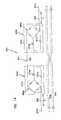
- FIG. 3is a schematic diagram of the DSX system of FIG. 2;
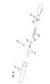
- FIG. 4shows the jumper assembly of FIG. 2 in isolation from the remainder of the DSX system
- FIG. 5is a schematic diagram of the jumper assembly of FIG. 4;
- FIG. 6is a schematic diagram illustrating current flow through the messenger wire of the jumper assembly when the switch of a left tracer lamp circuit is activated
- FIG. 7is a schematic diagram illustrating current flow through the messenger wire of the jumper assembly when the switch of a right tracer lamp circuit is activated
- FIG. 8is an exploded, perspective view of one of the tracer lamps that is integral with the messenger wire of the jumper assembly of FIGS. 4 and 5;
- FIG. 9is a cross-sectional view of the tracer lamp of FIG. 6 as assembled.
- FIG. 10illustrates an alternative tracer lamp configuration that is an example of how certain inventive concepts in accordance with the principles of the present disclosure can be practiced
- FIG. 12illustrates a further tracer lamp configuration that is an example of how certain inventive aspects in accordance with the principles of the present disclosure can be practiced
- FIG. 14is a schematic diagram of a further jumper assembly configuration that is an example of how certain inventive aspects in accordance with the principles of the present disclosure may be practiced;
- FIG. 16is an assembled, cross-sectional view of the tracer lamp configuration of FIG. 15 .
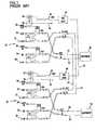
- FIG. 2illustrates a digital cross-connect (DSX) system 120 that is an example of how certain inventive aspects in accordance with the principles of the present disclosure can be practiced.
- the DSX system 120includes DSX modules 122 a , 122 b electrically connected to pieces of telecommunications equipment 123 a , 123 b by cables 125 a , 125 b (e.g., co-axial cables).
- the pieces of telecommunications equipment 123 a , 123 bare electrically connected to one another by a jumper assembly 124 that provides a cross-connection between the DSX modules 122 a , 122 b .
- the DSX modules 122 a , 122 binclude tracer lamps (e.g., LED's 150 a , 150 b ) that are visible from front ends of the modules 122 a , 122 b .
- the jumper assembly 124includes tracer lamp assemblies 134 a , 134 b that are visible from rear ends of the modules 122 a , 122 b.
- the DSX modules 122 a , 122 binclude IN switching jacks 144 a , 144 b and OUT switching jacks 146 a , 146 b that provide a means for temporarily breaking the cross-connections between the pieces of telecommunications equipment 123 a , 123 b to allow access to the IN and OUT signals for test and patching operations.
- the switching jacksinclude ports for receiving plugs used to access the IN and OUT signals.
- the switching jacksalso include switches for temporarily breaking the cross-connections when the plugs are inserted within the ports for test and patching operations. In a preferred embodiment, the switches can be make-before-break switches.
- the jumper assembly 124 of the cross-connect system 120includes two jumper cables 126 and 128 (i.e., cross-connect cables) and a messenger wire 130 .
- the term “messenger wire”includes any elongate electrically conductive member.
- the messenger wireis a copper wire.
- the jumper cables 126 , 128 and the messenger wire 130are bundled together by a sheath 132 to form the jumper assembly 124 .
- the messenger wire 130can be secured to the cables 126 , 128 by any number of different techniques such as tying, binding, strapping, etc.
- the messenger wire 130can be separate/separable from the jumper cables 126 , 128 .
- the tracer lamp assemblies 134 a , 134 bare carried with the messenger wire 130 .
- the tracer lamp assemblies 134 a , 134 bare mounted at opposite ends of the messenger wire 130 .
- lamp assembliescan be mounted at other locations along the length of the wire 130 .
- the jumper cables 126 , 128 of the jumper assembly 124are electrically coupled to rear ends of the modules 122 a , 122 b by connecters such as conventional coaxial connectors 127 a , 127 b (e.g., Bayonet Normalized Connectors (BNC), Threaded Normalized Connectors (TNC), 1.6/5.6 style connects, etc.). Similar connectors can be used to connect the cables 125 a , 125 b to the rear ends of the modules 122 a , 122 b.
- BNCBayonet Normalized Connectors
- TNCThreaded Normalized Connectors
- Similar connectorscan be used to connect the cables 125 a , 125 b to the rear ends of the modules 122 a , 122 b.
- the modules 122 a , 122 binclude tracer lamp circuits 121 a , 121 b .
- the tracer lamp circuits 121 a , 121 binclude tracer lamps (e.g., the front LED's 150 a , 150 b ).
- the LED's 150 a , 150 bare wired to power source contacts 152 a , 152 b and to ground contacts 154 a , 154 b .
- Switches 156 a , 156 bare positioned between the LED's 150 a , 150 b and their corresponding ground contacts 154 a , 154 b .
- the switches 156 a , 156 ballow the LED's 150 a , 150 b to be selectively connected to and disconnected from their corresponding ground contacts 154 a , 154 b.
- the wires connecting the switch 156 a , the LED 150 a , the power contact 152 a , the ground contact 154 a and the pin jack 160 aare not shown in FIG. 2 .
- the wiresare schematically depicted in FIG. 3 .
- the tracer lamp assemblies 134 a , 134 bare located at opposite ends of the messenger wire 130 (see FIG. 4 ).
- the assembliesinclude translucent housings 172 a , 172 b from which the conductive pins 170 a , 170 b project.
- the tracer lamp assemblies 134 a , 134 balso include structure for illuminating the housings 172 a , 172 b .
- LED's 174 a , 174 bare mounted within each of the housings 172 a 172 b .
- the LED's 174 a , 174 bcan include conventional flasher circuitry for causing the LED's 174 a , 174 b to flash for a predetermined length of time when activated and then turn to steady-on. In other embodiments, steady-on LED's can also be used without using flashing circuitry.
- the tracer lamp assemblies 134 a , 134 balso include resistors 178 a , 178 b positioned in series with the LED's 174 a , 174 b . Illumination devices (e.g., lamps) other than LED's could also be used.
- the rectifier circuits 180 a , 180 bcause both LED's 174 a , 174 b to be illuminated (see FIG. 7 where arrows have been added to show the direction of electrical current flow).
- the LED's 150 a , 150 bas well as the LED's 174 a , 174 b illuminate whenever either of the switches 158 a , 158 b are closed.
- the housing 172 a of the tracer lamp assembly 134 ahas a two-piece configuration including a main housing piece 202 and a housing cap 203 .
- the housing 172 ais sized to hold a number of tracer lamp components such as the conductive pin 170 a , a circuit board assembly 250 , and a double-crimp conductor 270 .
- the housing 172 ais preferably made of a translucent material such as translucent plastic.
- the housing 172 acan be transparent, opaque or tinted with a color (e.g., red, yellow, amber, blue, green, etc.).
- the main housing piece 202 of the housing 172 ahas a hollow, cylindrical configuration and includes a first end 204 positioned opposite from a second end 206 .
- An annular, outer retaining shoulder 208is located adjacent the second end 206 .
- An inner, annular retaining shoulder 210(shown in FIG. 9) is located adjacent the first end 204 .
- the conductive pin 170 a of the tracer lamp assembly 134 aincludes a first end 220 (i.e., a tip end) positioned opposite from a second end 224 (i.e., a base end).
- the conductive pin 170 aalso includes a resilient tab 226 spaced from a retaining shoulder 228 .
- a crimping structure 230is located at the second end 224 of the conductive pin 170 a.
- the circuit board assembly 250 of the tracer lamp assembly 134 aincludes an elongate circuit board 252 .
- the rectifier circuit 180 a , the LED 174 a and the resistor 178 aare mounted on the circuit board 252 .
- the circuit board 252preferably includes tracings for electrically connecting the rectifier circuit 184 a , the LED 174 a and the resistor 178 a in a manner consistent with the schematic shown in FIG. 5 .
- the circuit board assembly 250also includes conductive pins 254 and 256 that project outwardly from opposite ends of the elongate circuit board 252 . It will be appreciated that tracings electrically connect the conductive pins 254 and 256 to the components on the circuit board 252 .
- the double-crimp conductor 270 of the tracer lamp assembly 134 aincludes a first crimping structure 272 positioned at an opposite end from a second crimping structure 274 .
- An enlarged alignment structure 276is positioned between the crimping structures 272 , 274 .
- the tracer lamp assembly 134 ais assembled by initially performing a sequence of crimping steps.
- the first conductive pin 254 of the circuit board assembly 250can be crimped within the crimping structure 230 of the pin 170 a .
- the second conductive pin 256 of the circuit board assembly 250can be crimped within the crimping structure 272 of the double crimp conductor 270 .
- a stripped end of the messenger wire 130can be inserted through the cap 203 of the housing 172 a and crimped within the crimping structure 274 of the double crimped conductor 270 .
- the entire crimped assemblyis inserted through the second end 206 of the main housing piece 202 .
- the assemblyis pushed toward the first end 204 of the main housing piece 202 until the resilient tab 226 of the pin 170 a snaps past the inner shoulder 210 of the housing piece 202 as shown in FIG. 9 .
- the shoulder 210is trapped between the resilient tab 226 and the retaining shoulder 228 of the conductive pin 170 a . This limits axial movement of the conductive pin 170 a relative to the housing 172 a.
- the first end 220 of the conductive pin 170 aprojects axially outwardly from the first end 204 of the main housing piece 202 , and the circuit board assembly 250 is enclosed within an internal cavity of the main housing piece 202 .
- the alignment structure 276 of the double-crimp conductor 270fits within the second end 206 of the main housing piece 202 to assist in aligning the crimping structures 272 , 274 with a center axis of the housing 272 a .
- the pin 127 aalso co-axially aligns with the housing 172 a.
- FIG. 10shows an alternate tracer lamp assembly 300 that is an embodiment of certain inventive aspects in accordance with the principles of the present disclosure.
- the assembly 300includes a translucent housing 302 having a hollow, cylindrical configuration.
- Tracer lamp circuitryis mounted within the housing.
- the tracer lamp circuitryincludes a conductive pin 304 , a circuit board 306 , and a crimping structure 308 .
- the conductive pin 304 and the conductive crimping structure 308are connected to the circuit board 306 by a surface mount connection technique.
- An LED 310 and a resistor 312are also surface mounted on the circuit board 306 by a surface mount connection technique.
- the conductive pin 304includes a threaded portion 314 having external threads that thread within corresponding internal threads (not shown) within the housing 302 to hold the tracer lamp circuitry within the housing.
- the tracer lamp circuitryis inserted through a first end 303 of the housing 302 and threaded into a locked position where the conductive pin 304 projects from the first end 303 of the housing 302 and the crimping structure 308 aligns with a clearance hole 307 defined at a second end 309 of the housing 302 .
- the assembly 300also includes a rectifier circuit. However, other configurations for routing current through the LED 310 in the proper illumination direction can also be used.
- FIG. 11illustrates another tracer lamp assembly 400 that is an embodiment of certain inventive aspects in accordance with the principles of the present disclosure.
- the assembly 400has the same configuration as the assembly of FIG. 10 except a resistor 412 and an LED 410 are mounted to a circuit board by a through-hole connection technique (e.g., by soldering wires within plated through-holes of the circuit board) as compared to a surface mount connection technique (e.g., by mounting the components to conductive pads on the circuit board).
- the depicted embodiments of FIGS. 10 and 12are used with unidirectional current through the messenger wire.
- Other embodimentscan be bi-directional through the use of rectifier circuits as previously described or diodes arranged in parallel as described in the embodiment of FIG. 13 .
- FIG. 12illustrates still another tracer lamp assembly 134 ′ that is an embodiment of certain inventive aspects in accordance with the principles of the present disclosure.
- the assembly 134 ′has the same configuration as the assembly 134 a of FIG. 8 except that modifications have been made to shorten the assembly to facilitate cable management.
- a first crimping structure 272 ′ of a double-crimp conductor 270 ′has been shortened as compared to the first crimping structure 272 of the double crimp conductor 270 .
- conductive pin 170 ′does not include a crimping structure.
- a second end 224 ′(i.e., a base end) of the pin 170 ′ is soldered to the conductive pin 254 of the circuit board assembly 250 .
- a housing 172 ′ of the assembly 134 ′has been shortened as compared to the housing 172 of the assembly 134 a.
- FIG. 13is a schematic diagram of another jumper assembly 500 that is an example of how certain inventive aspects disclosed herein may be practiced.
- the jumper assembly 500includes two jumper cables 502 , 504 and a messenger wire 506 .
- Light emitting diode structures 508are carried with the messenger wire 506 .
- Each light emitting diode structure 508includes a housing 510 containing two light emitting diodes 512 , 514 .
- the light emitting diodes 512 , 514are aligned in parallel and have opposite current pass directions. This configuration ensures that the light emitting diode structures 508 will illuminate regardless of the direction of current flow through the messenger wire 506 .
- the diodes 514will illuminate when current flows from right to left through the messenger wire 506
- the diodes 512will illuminate when current flows from left to right through the messenger wire 506 .
- FIG. 14schematically shows an alternative jumper assembly 624 with an integral tracer lamp that is an embodiment of certain inventive aspects in accordance with the principles of the present disclosure.
- the jumper assembly 624includes jumper cables 626 and 628 and a messenger wire 630 that is preferably secured to the jumper cables 626 , 628 .
- Tracer lamps 634 a , 634 bare carried with the messenger wire 630 .
- the tracer lamps 634 a , 634 bare shown including translucent housings 672 a , 672 b containing LED's 674 a , 674 b , rectifier circuits 680 a , 680 b and resistors 671 a , 671 b .
- LED's 674 a , 674 brectifier circuits 680 a , 680 b
- resistors 671 a , 671 bresistors
- conductive pins 670 a , 670 bare mounted at opposite ends of the messenger wire 630 .
- the pins 670 a , 670 bare adapted to be received within sockets of conventional pin jacks.
- the tracer light structures 634 a , 634 bare offset from the conductive pins 670 a , 670 b .
- a spacing Sseparates each of the tracer lamp structures 634 a , 634 b from its respective conductive pin 670 a , 670 b .
- the spacingis from 2-9 inches. In a more preferred embodiment, the spacing is from 3-6 inches.
- the tracer lamp structures 634 a , 634 bare shown positioned in line with the messenger wire 630 .
- the messenger wire 630includes a first portion 650 that extends between the tracer lamp structures 634 a , 634 b , a second portion 652 that traverses the spacing between the conductive pin 670 a and the tracer lamp structure 634 a , and a third portion 654 that traverses the spacing between the conductive pin 670 b and the tracer lamp structure 634 b .
- the spacings provided by the portions 652 , 654 of the messenger wire 630assist in promoting cable management and also assist in allowing the tracer lamp structures 634 a , 634 b to be positioned at a location of increased visibility (e.g., offset a predetermined distance from a corresponding rack).
- FIGS. 15 and 16illustrate an exemplary configuration for the tracer lamp structure 634 a . It will be appreciated that the tracer lamp structure 634 b can have the same configuration.
- the translucent housing 672 a of the tracer lamp structure 634 aincludes a middle portion 602 and two snap fit end caps 603 .
- the end caps 603are adapted to snap on the middle piece 602 in the same manner that the cap 203 of the housing 172 a of FIG. 8 snaps onto the main housing piece 202 .
- the tracer lamp structure 634 aalso includes a circuit board assembly 690 including a circuit board 691 on which the rectifier circuit 680 a , the diode 674 a and the resistor 671 a are mounted. Tracings (not shown) can connect the circuit components in a manner consistent with the schematic of FIG. 14 .
- Conductive pins 694 and 695project outwardly from the circuit board 691 .
- the conductive pins 694 , 695provide connection locations for coupling the components of the circuit board assembly 690 to double crimps 696 , 697 .
- FIG. 16shows the crimps 696 , 697 crimped upon the conductive pins 694 , 695 .
- the circuit board assembly 690mounts within the housing 672 a .
- the double crimps 696 , 697include centering members 699 for centering the circuit board assembly 690 within the housing 672 a .
- the crimps 696 , 697provide means for coupling the first and second portions 650 , 652 of the messenger wire 630 to the circuit board assembly 690 .
- the end caps 603have been omitted from FIG. 16 for clarity.
- each of the depicted embodimentsshows tracer lamps positioned directly in-line with their corresponding messenger wires.
- the tracer lampscan be indirectly coupled to their corresponding messenger wires by techniques such as an inductive coupling.
Landscapes
- Arrangement Of Elements, Cooling, Sealing, Or The Like Of Lighting Devices (AREA)
Abstract
Description
Claims (34)
Priority Applications (2)
| Application Number | Priority Date | Filing Date | Title |
|---|---|---|---|
| US10/219,809US6743044B2 (en) | 2002-08-14 | 2002-08-14 | Cross-connect jumper assembly having tracer lamp |
| US10/857,509US6905363B2 (en) | 2002-08-14 | 2004-05-28 | Cross-connect jumper assembly having tracer lamp |
Applications Claiming Priority (1)
| Application Number | Priority Date | Filing Date | Title |
|---|---|---|---|
| US10/219,809US6743044B2 (en) | 2002-08-14 | 2002-08-14 | Cross-connect jumper assembly having tracer lamp |
Related Child Applications (1)
| Application Number | Title | Priority Date | Filing Date |
|---|---|---|---|
| US10/857,509ContinuationUS6905363B2 (en) | 2002-08-14 | 2004-05-28 | Cross-connect jumper assembly having tracer lamp |
Publications (2)
| Publication Number | Publication Date |
|---|---|
| US20040033716A1 US20040033716A1 (en) | 2004-02-19 |
| US6743044B2true US6743044B2 (en) | 2004-06-01 |
Family
ID=31714802
Family Applications (2)
| Application Number | Title | Priority Date | Filing Date |
|---|---|---|---|
| US10/219,809Expired - LifetimeUS6743044B2 (en) | 2002-08-14 | 2002-08-14 | Cross-connect jumper assembly having tracer lamp |
| US10/857,509Expired - LifetimeUS6905363B2 (en) | 2002-08-14 | 2004-05-28 | Cross-connect jumper assembly having tracer lamp |
Family Applications After (1)
| Application Number | Title | Priority Date | Filing Date |
|---|---|---|---|
| US10/857,509Expired - LifetimeUS6905363B2 (en) | 2002-08-14 | 2004-05-28 | Cross-connect jumper assembly having tracer lamp |
Country Status (1)
| Country | Link |
|---|---|
| US (2) | US6743044B2 (en) |
Cited By (38)
| Publication number | Priority date | Publication date | Assignee | Title |
|---|---|---|---|---|
| US20050186840A1 (en)* | 2002-12-06 | 2005-08-25 | Holliday Randall A. | Adapter for coaxial cable with interchangeable color bands |
| US20050281032A1 (en)* | 2004-06-21 | 2005-12-22 | Petersen Cyle D | Press-in place LED for a digital switching cross-connect module |
| WO2006044177A3 (en)* | 2004-10-13 | 2006-09-14 | Nortel Networks Ltd | Fiber tracer patch cord |
| US20070161268A1 (en)* | 2006-01-10 | 2007-07-12 | Klaus Muschketat | Casing termination for electronic casing and method for its manufacture |
| US20070230452A1 (en)* | 2006-03-22 | 2007-10-04 | Steve Hough | Intelligent patching system and method |
| US20080171466A1 (en)* | 2007-01-11 | 2008-07-17 | Bruce Dascombe Buck | Cable connector with bushing that permits visual verification |
| US20090215323A1 (en)* | 2008-02-20 | 2009-08-27 | Hsing-Wang Chang | Power plug assembly |
| US20090215310A1 (en)* | 2006-10-10 | 2009-08-27 | Adc Gmbh | Upgradeable telecommunications patch panel and method of upgrading same |
| US20100093211A1 (en)* | 2008-10-13 | 2010-04-15 | Sutter Robert W | Coaxial Cable Connector |
| US20100202741A1 (en)* | 2009-02-06 | 2010-08-12 | Draka Comteq B.V. | Central-Tube Cable with High-Conductivity Conductors Encapsulated with High-Dielectric-Strength Insulation |
| US20110116748A1 (en)* | 2009-10-16 | 2011-05-19 | Adc Telecommunications, Inc. | Managed connectivity in fiber optic systems and methods thereof |
| US20110228473A1 (en)* | 2010-02-12 | 2011-09-22 | Chad Anderson | Communications bladed panel systems |
| US20110235979A1 (en)* | 2010-02-12 | 2011-09-29 | John Anderson | Managed fiber connectivity systems |
| US20110256769A1 (en)* | 2010-04-19 | 2011-10-20 | Hon Hai Precision Industry Co., Ltd. | Cable assembly having indicating device |
| US8540529B2 (en)* | 2011-08-02 | 2013-09-24 | Conexant Systems, Inc. | Shielded USB connector module with molded hood and LED light pipe |
| US8565572B2 (en) | 2010-06-23 | 2013-10-22 | Adc Telecommunications, Inc. | Telecommunications assembly |
| US8696369B2 (en) | 2010-09-09 | 2014-04-15 | Adc Telecommunications, Inc. | Electrical plug with main contacts and retractable secondary contacts |
| US8715012B2 (en) | 2011-04-15 | 2014-05-06 | Adc Telecommunications, Inc. | Managed electrical connectivity systems |
| US8757895B2 (en) | 2011-04-15 | 2014-06-24 | Adc Telecommunications, Inc. | Managed fiber connectivity systems |
| US8897637B2 (en) | 2009-04-22 | 2014-11-25 | Adc Gmbh | Method and arrangement for identifying at least one object |
| US8992261B2 (en) | 2010-10-22 | 2015-03-31 | Adc Telecommunications, Inc. | Single-piece plug nose with multiple contact sets |
| US8992260B2 (en) | 2009-10-16 | 2015-03-31 | Adc Telecommunications, Inc. | Managed connectivity in electrical systems and methods thereof |
| US9054440B2 (en) | 2009-10-19 | 2015-06-09 | Adc Telecommunications, Inc. | Managed electrical connectivity systems |
| US9064022B2 (en) | 2011-05-17 | 2015-06-23 | Adc Telecommunications, Inc. | Component identification and tracking system for telecommunication networks |
| US9093796B2 (en) | 2012-07-06 | 2015-07-28 | Adc Telecommunications, Inc. | Managed electrical connectivity systems |
| US9203198B2 (en) | 2012-09-28 | 2015-12-01 | Commscope Technologies Llc | Low profile faceplate having managed connectivity |
| US9219543B2 (en) | 2012-07-11 | 2015-12-22 | Commscope Technologies Llc | Monitoring optical decay in fiber connectivity systems |
| US9285552B2 (en) | 2013-02-05 | 2016-03-15 | Commscope Technologies Llc | Optical assemblies with managed connectivity |
| US9379501B2 (en) | 2013-02-05 | 2016-06-28 | Commscope Technologies Llc | Optical assemblies with managed connectivity |
| US9423570B2 (en) | 2013-02-05 | 2016-08-23 | Commscope Technologies Llc | Optical assemblies with managed connectivity |
| US9453971B2 (en) | 2012-07-11 | 2016-09-27 | Commscope Technologies Llc | Managed fiber connectivity systems |
| US9470742B2 (en) | 2012-08-03 | 2016-10-18 | Commscope Technologies Llc | Managed fiber connectivity systems |
| US9500814B2 (en) | 2014-03-26 | 2016-11-22 | Commscope Technologies Llc | Optical adapter module with managed connectivity |
| US9798096B2 (en) | 2014-02-07 | 2017-10-24 | Commscope Technologies Llc | Managed fiber connectivity systems |
| US10234648B2 (en) | 2007-08-06 | 2019-03-19 | Commscope Technologies Llc | Fiber optic enclosure with internal cable spool |
| US10371914B2 (en) | 2011-06-24 | 2019-08-06 | Commscope Technologies Llc | Fiber termination enclosure with modular plate assemblies |
| US10545305B2 (en) | 2012-12-19 | 2020-01-28 | CommScope Connectivity Belgium BVBA | Distribution device with incrementally added splitters |
| US10627592B2 (en) | 2007-05-07 | 2020-04-21 | Commscope Technologies Llc | Fiber optic assembly with cable spool |
Families Citing this family (15)
| Publication number | Priority date | Publication date | Assignee | Title |
|---|---|---|---|---|
| US6848948B1 (en)* | 2003-11-03 | 2005-02-01 | Adc Telecommunications, Inc. | Jack with modular mounting sleeve |
| TWI229737B (en)* | 2003-11-13 | 2005-03-21 | Benq Corp | Plug detecting device |
| WO2006115813A1 (en)* | 2005-04-21 | 2006-11-02 | Adc Telecommunications, Inc. | Modular mounting sleeve for jack |
| US7074080B1 (en)* | 2005-04-21 | 2006-07-11 | Adc Telecommunications, Inc. | Modular mounting sleeve for jack |
| US7811119B2 (en) | 2005-11-18 | 2010-10-12 | Panduit Corp. | Smart cable provisioning for a patch cord management system |
| US7591677B2 (en)* | 2006-04-21 | 2009-09-22 | Adc Telecommunications, Inc. | High density coaxial jack and panel |
| CA2572755A1 (en)* | 2007-01-03 | 2008-07-03 | Ken Shipalesky | Wire-line connection system |
| US8477031B2 (en) | 2007-10-19 | 2013-07-02 | Panduit Corp. | Communication port identification system |
| JP5341920B2 (en) | 2008-02-21 | 2013-11-13 | パンドウィット・コーポレーション | Intelligent interconnect and cross-connect patching system |
| CN201203010Y (en)* | 2008-05-23 | 2009-03-04 | 陈兴建 | A kind of LED lamp and lamp string which can prevent circuit breaking |
| US8306935B2 (en) | 2008-12-22 | 2012-11-06 | Panduit Corp. | Physical infrastructure management system |
| EP3301767B1 (en) | 2008-12-31 | 2020-11-04 | Panduit Corp | Patch cord with insertion detection and light illumination capabilities |
| US8128428B2 (en) | 2009-02-19 | 2012-03-06 | Panduit Corp. | Cross connect patch guidance system |
| US10780820B1 (en)* | 2019-05-23 | 2020-09-22 | Inview Vehicle Trim Corp. | Vehicle door pillar light assembly and method of use thereof |
| CA3218922A1 (en)* | 2021-05-03 | 2022-11-10 | Hubbell Incorporated | Tracer wire jumpers and pigtails |
Citations (20)
| Publication number | Priority date | Publication date | Assignee | Title |
|---|---|---|---|---|
| US3859646A (en)* | 1971-08-27 | 1975-01-07 | Robert D Schwellenbach | Inline continuity indicator device |
| US4600810A (en)* | 1984-09-07 | 1986-07-15 | Amp Incorporated | Telephone line tester |
| US4653848A (en) | 1983-06-23 | 1987-03-31 | Jacobus Kloots | Fiberoptic cables with angled connectors |
| US4707073A (en) | 1985-09-04 | 1987-11-17 | Raytheon Company | Fiber optic beam delivery system for high-power laser |
| US4749968A (en) | 1985-12-13 | 1988-06-07 | Adc Telecommunications, Inc. | Jack device |
| US4887190A (en) | 1988-10-15 | 1989-12-12 | In Focis Devices Inc. | High intensity fiber optic lighting system |
| US4969834A (en)* | 1989-10-02 | 1990-11-13 | Johnson Robert A | Jumper cable apparatus |
| US4978194A (en) | 1989-08-28 | 1990-12-18 | Raynet Corporation | Stepped cable block |
| US5193087A (en)* | 1990-05-16 | 1993-03-09 | Tadiran, Ltd. | Electronic digital cross-connect system having bipolar violation transparency |
| US5228109A (en) | 1990-08-24 | 1993-07-13 | Matsushita Electric Industrial Co., Ltd. | Light beam heating apparatus and method utilizing a fiber optic cable with random fiber array |
| US5305405A (en) | 1993-02-25 | 1994-04-19 | Adc Telecommunications, Inc. | Patch cord |
| US5393249A (en)* | 1993-06-30 | 1995-02-28 | Adc Telecommunications, Inc. | Rear cross connect DSX system |
| US5554049A (en)* | 1993-08-19 | 1996-09-10 | Woodhead Industries, Inc. | Inline indicating interconnect |
| US5913701A (en) | 1997-02-28 | 1999-06-22 | Adc Telecommunications, Inc. | DSX module with removable switching jack |
| US5964616A (en)* | 1995-07-19 | 1999-10-12 | United Industrial Trading Corp. | Lighted accessory power supply cord |
| US6116961A (en) | 1998-11-12 | 2000-09-12 | Adc Telecommunications, Inc. | Jack assembly |
| US6290533B1 (en)* | 1999-10-05 | 2001-09-18 | Jane Major | Flashlight plug |
| US6361357B1 (en)* | 2000-04-13 | 2002-03-26 | 3Com Corporation | Remotely illuminated electronic connector for improving viewing of status indicators |
| US6422902B1 (en)* | 2000-11-10 | 2002-07-23 | Adc Telecommunications, Inc. | Low profile telecommunications jack with lamp switch |
| US6431906B1 (en)* | 2001-02-28 | 2002-08-13 | Fci Americas Technology, Inc. | Modular connectors with detachable line status indicators |
Family Cites Families (3)
| Publication number | Priority date | Publication date | Assignee | Title |
|---|---|---|---|---|
| US6619993B2 (en)* | 2001-06-01 | 2003-09-16 | Robert Jayne | DSX jack connection system |
| US6551136B2 (en)* | 2001-09-20 | 2003-04-22 | Adc Telecommunications, Inc. | Closed end coaxial connector |
| US6830487B2 (en)* | 2002-07-19 | 2004-12-14 | Adc Telecommunications, Inc. | Pin jack for a digital switching cross-connect module |
- 2002
- 2002-08-14USUS10/219,809patent/US6743044B2/ennot_activeExpired - Lifetime
- 2004
- 2004-05-28USUS10/857,509patent/US6905363B2/ennot_activeExpired - Lifetime
Patent Citations (20)
| Publication number | Priority date | Publication date | Assignee | Title |
|---|---|---|---|---|
| US3859646A (en)* | 1971-08-27 | 1975-01-07 | Robert D Schwellenbach | Inline continuity indicator device |
| US4653848A (en) | 1983-06-23 | 1987-03-31 | Jacobus Kloots | Fiberoptic cables with angled connectors |
| US4600810A (en)* | 1984-09-07 | 1986-07-15 | Amp Incorporated | Telephone line tester |
| US4707073A (en) | 1985-09-04 | 1987-11-17 | Raytheon Company | Fiber optic beam delivery system for high-power laser |
| US4749968A (en) | 1985-12-13 | 1988-06-07 | Adc Telecommunications, Inc. | Jack device |
| US4887190A (en) | 1988-10-15 | 1989-12-12 | In Focis Devices Inc. | High intensity fiber optic lighting system |
| US4978194A (en) | 1989-08-28 | 1990-12-18 | Raynet Corporation | Stepped cable block |
| US4969834A (en)* | 1989-10-02 | 1990-11-13 | Johnson Robert A | Jumper cable apparatus |
| US5193087A (en)* | 1990-05-16 | 1993-03-09 | Tadiran, Ltd. | Electronic digital cross-connect system having bipolar violation transparency |
| US5228109A (en) | 1990-08-24 | 1993-07-13 | Matsushita Electric Industrial Co., Ltd. | Light beam heating apparatus and method utilizing a fiber optic cable with random fiber array |
| US5305405A (en) | 1993-02-25 | 1994-04-19 | Adc Telecommunications, Inc. | Patch cord |
| US5393249A (en)* | 1993-06-30 | 1995-02-28 | Adc Telecommunications, Inc. | Rear cross connect DSX system |
| US5554049A (en)* | 1993-08-19 | 1996-09-10 | Woodhead Industries, Inc. | Inline indicating interconnect |
| US5964616A (en)* | 1995-07-19 | 1999-10-12 | United Industrial Trading Corp. | Lighted accessory power supply cord |
| US5913701A (en) | 1997-02-28 | 1999-06-22 | Adc Telecommunications, Inc. | DSX module with removable switching jack |
| US6116961A (en) | 1998-11-12 | 2000-09-12 | Adc Telecommunications, Inc. | Jack assembly |
| US6290533B1 (en)* | 1999-10-05 | 2001-09-18 | Jane Major | Flashlight plug |
| US6361357B1 (en)* | 2000-04-13 | 2002-03-26 | 3Com Corporation | Remotely illuminated electronic connector for improving viewing of status indicators |
| US6422902B1 (en)* | 2000-11-10 | 2002-07-23 | Adc Telecommunications, Inc. | Low profile telecommunications jack with lamp switch |
| US6431906B1 (en)* | 2001-02-28 | 2002-08-13 | Fci Americas Technology, Inc. | Modular connectors with detachable line status indicators |
Cited By (147)
| Publication number | Priority date | Publication date | Assignee | Title |
|---|---|---|---|---|
| US20050186840A1 (en)* | 2002-12-06 | 2005-08-25 | Holliday Randall A. | Adapter for coaxial cable with interchangeable color bands |
| US7156695B2 (en)* | 2002-12-06 | 2007-01-02 | Holliday Randall A | Adapter for coaxial cable with interchangeable color bands |
| US20050281032A1 (en)* | 2004-06-21 | 2005-12-22 | Petersen Cyle D | Press-in place LED for a digital switching cross-connect module |
| US7182502B2 (en)* | 2004-06-21 | 2007-02-27 | Adc Telecommunications, Inc. | Press-in place LED for a digital switching cross-connect module |
| CN101006735B (en)* | 2004-06-21 | 2010-05-12 | Adc电信公司 | Press-in placed LED for a digital switching cross-connect module |
| US20070223254A1 (en)* | 2004-06-21 | 2007-09-27 | Adc Telecommunications, Inc. | Press-in place LED for a digital switching cross-connect module |
| US7553063B2 (en) | 2004-06-21 | 2009-06-30 | Adc Telecommunications, Inc. | Press-in place LED for a digital switching cross-connect module |
| WO2006044177A3 (en)* | 2004-10-13 | 2006-09-14 | Nortel Networks Ltd | Fiber tracer patch cord |
| US7316575B2 (en)* | 2006-01-10 | 2008-01-08 | Pepperl & Fuchs Gmbh | Casing termination for electronic casing and method for its manufacture |
| US20070161268A1 (en)* | 2006-01-10 | 2007-07-12 | Klaus Muschketat | Casing termination for electronic casing and method for its manufacture |
| US20070230452A1 (en)* | 2006-03-22 | 2007-10-04 | Steve Hough | Intelligent patching system and method |
| US7869426B2 (en) | 2006-03-22 | 2011-01-11 | Adc Gmbh | Intelligent patching system and method |
| US20090215310A1 (en)* | 2006-10-10 | 2009-08-27 | Adc Gmbh | Upgradeable telecommunications patch panel and method of upgrading same |
| US7641513B2 (en) | 2006-10-10 | 2010-01-05 | Adc Gmbh | Upgradeable telecommunications patch panel and method of upgrading same |
| US7811123B2 (en) | 2006-10-10 | 2010-10-12 | Adc Gmbh | Upgradeable telecommunications patch panel and method of upgrading same |
| US20100184324A1 (en)* | 2006-10-10 | 2010-07-22 | Adc Gmbh | Upgradeable telecommunications patch panel and method of upgrading same |
| US7976339B2 (en)* | 2007-01-11 | 2011-07-12 | Ideal Industries, Inc. | Cable connector with bushing that permits visual verification |
| US20080171466A1 (en)* | 2007-01-11 | 2008-07-17 | Bruce Dascombe Buck | Cable connector with bushing that permits visual verification |
| US12235506B2 (en) | 2007-05-07 | 2025-02-25 | Commscope Technologies Llc | Fiber optic enclosure with external cable spool |
| US10627592B2 (en) | 2007-05-07 | 2020-04-21 | Commscope Technologies Llc | Fiber optic assembly with cable spool |
| US10788642B2 (en) | 2007-05-07 | 2020-09-29 | Commscope Technologies Llc | Fiber optic assembly with cable storage arrangement |
| US11009671B2 (en) | 2007-05-07 | 2021-05-18 | Commscope Technologies Llc | Fiber optic assembly with cable storage arrangement |
| US10606017B2 (en) | 2007-08-06 | 2020-03-31 | Commscope Technologies Llc | Fiber optic payout assembly including cable spool |
| US10606015B2 (en) | 2007-08-06 | 2020-03-31 | Commscope Technologies Llc | Fiber optic payout assembly including cable spool |
| US12253734B2 (en) | 2007-08-06 | 2025-03-18 | Commscope Technologies Llc | Fiber optic enclosure with internal cable spool |
| US10495836B2 (en) | 2007-08-06 | 2019-12-03 | Commscope Technologies Llc | Fiber optic payout assembly including cable spool |
| US10712518B2 (en) | 2007-08-06 | 2020-07-14 | Commscope Technologies Llc | Fiber optic enclosure with lockable internal cable spool |
| US12019301B2 (en) | 2007-08-06 | 2024-06-25 | Commscope Technologies Llc | Fiber optic enclosure with internal cable spool |
| US10247897B2 (en) | 2007-08-06 | 2019-04-02 | Commscope Technologies Llc | Fiber optic enclosure with internal cable spool |
| US10895705B2 (en) | 2007-08-06 | 2021-01-19 | Commscope Technologies Llc | Fiber optic enclosure with internal cable spool |
| US10996417B2 (en) | 2007-08-06 | 2021-05-04 | Commscope Technologies Llc | Fiber optic enclosure with internal cable spool and movable cover |
| US11573390B2 (en) | 2007-08-06 | 2023-02-07 | Commscope Technologies Llc | Fiber optic enclosure with internal cable spool |
| US10996418B2 (en) | 2007-08-06 | 2021-05-04 | Commscope Technologies Llc | Connecting subscribers to a fiber optic network using a cable spool |
| US10234648B2 (en) | 2007-08-06 | 2019-03-19 | Commscope Technologies Llc | Fiber optic enclosure with internal cable spool |
| US7677916B2 (en)* | 2008-02-20 | 2010-03-16 | Taiwan Line Tek Electronic Co., Ltd. | Power plug assembly |
| US20090215323A1 (en)* | 2008-02-20 | 2009-08-27 | Hsing-Wang Chang | Power plug assembly |
| US20100093211A1 (en)* | 2008-10-13 | 2010-04-15 | Sutter Robert W | Coaxial Cable Connector |
| US7914326B2 (en) | 2008-10-13 | 2011-03-29 | Ideal Industries, Inc. | Coaxial cable connector |
| US9360647B2 (en)* | 2009-02-06 | 2016-06-07 | Draka Comteq, B.V. | Central-tube cable with high-conductivity conductors encapsulated with high-dielectric-strength insulation |
| US20100202741A1 (en)* | 2009-02-06 | 2010-08-12 | Draka Comteq B.V. | Central-Tube Cable with High-Conductivity Conductors Encapsulated with High-Dielectric-Strength Insulation |
| US8897637B2 (en) | 2009-04-22 | 2014-11-25 | Adc Gmbh | Method and arrangement for identifying at least one object |
| US20110116748A1 (en)* | 2009-10-16 | 2011-05-19 | Adc Telecommunications, Inc. | Managed connectivity in fiber optic systems and methods thereof |
| US9967983B2 (en) | 2009-10-16 | 2018-05-08 | Commscope Technologies Llc | Managed connectivity in electrical systems and methods thereof |
| US9401552B2 (en) | 2009-10-16 | 2016-07-26 | Commscope Technologies Llc | Managed connectivity in electrical systems and methods thereof |
| US9769939B2 (en) | 2009-10-16 | 2017-09-19 | Commscope Technologies Llc | Managed connectivity in electrical systems and methods thereof |
| US12235494B2 (en) | 2009-10-16 | 2025-02-25 | Commscope Technologies Llc | Managed connectivity in fiber optic systems and methods thereof |
| US10678001B2 (en) | 2009-10-16 | 2020-06-09 | Commscope Technologies Llc | Managed connectivity in fiber optic systems and methods thereof |
| US8992260B2 (en) | 2009-10-16 | 2015-03-31 | Adc Telecommunications, Inc. | Managed connectivity in electrical systems and methods thereof |
| US11191173B2 (en) | 2009-10-16 | 2021-11-30 | Commscope Technologies Llc | Managed connectivity in electrical systems and methods thereof |
| US9176294B2 (en) | 2009-10-16 | 2015-11-03 | Tyco Electronics Services Gmbh | Managed connectivity in fiber optic systems and methods thereof |
| US8596882B2 (en) | 2009-10-16 | 2013-12-03 | Adc Telecommunications, Inc. | Managed connectivity in fiber optic systems and methods thereof |
| US9810860B2 (en) | 2009-10-16 | 2017-11-07 | Commscope Technologies Llc | Managed connectivity in fiber optic systems and methods thereof |
| US11630269B2 (en) | 2009-10-16 | 2023-04-18 | Commscope Technologies Llc | Managed connectivity in fiber optic systems and methods thereof |
| US10470320B2 (en) | 2009-10-16 | 2019-11-05 | Commscope Technologies Llc | Managed connectivity in electrical systems and methods thereof |
| US11231555B2 (en) | 2009-10-16 | 2022-01-25 | Commscope Technologies Llc | Managed connectivity in fiber optic systems and methods thereof |
| US9595797B2 (en) | 2009-10-19 | 2017-03-14 | Commscope Technologies Llc | Managed electrical connectivity systems |
| US10177514B2 (en) | 2009-10-19 | 2019-01-08 | Commscope Technologies Llc | Managed electrical connectivity systems |
| US11469560B2 (en) | 2009-10-19 | 2022-10-11 | Commscope Technologies Llc | Managed electrical connectivity systems |
| US10574008B2 (en) | 2009-10-19 | 2020-02-25 | Commscope Technologies Llc | Managed electrical connectivity systems |
| US10958024B2 (en) | 2009-10-19 | 2021-03-23 | Commscope Technologies Llc | Managed electrical connectivity systems |
| US11862912B2 (en) | 2009-10-19 | 2024-01-02 | Commscope Technologies Llc | Managed electrical connectivity systems |
| US9054440B2 (en) | 2009-10-19 | 2015-06-09 | Adc Telecommunications, Inc. | Managed electrical connectivity systems |
| US8923013B2 (en) | 2010-02-12 | 2014-12-30 | Adc Telecommunications, Inc. | Communications bladed panel systems |
| US8934253B2 (en) | 2010-02-12 | 2015-01-13 | Adc Telecommunications, Inc. | Communications bladed panel systems |
| US12306444B2 (en) | 2010-02-12 | 2025-05-20 | Commscope Technologies Llc | Managed fiber connectivity systems |
| US20110228473A1 (en)* | 2010-02-12 | 2011-09-22 | Chad Anderson | Communications bladed panel systems |
| US20110235979A1 (en)* | 2010-02-12 | 2011-09-29 | John Anderson | Managed fiber connectivity systems |
| US9140859B2 (en) | 2010-02-12 | 2015-09-22 | Tyco Electronics Services Gmbh | Managed fiber connectivity systems |
| US9198320B2 (en) | 2010-02-12 | 2015-11-24 | Tyco Electronics Services Gmbh | Communications bladed panel systems |
| US9020319B2 (en) | 2010-02-12 | 2015-04-28 | Adc Telecommunications, Inc. | Communications bladed panel systems |
| US9532481B2 (en) | 2010-02-12 | 2016-12-27 | Commscope Technologies Llc | Communications bladed panel systems |
| US9532482B2 (en) | 2010-02-12 | 2016-12-27 | Commscope Technologies Llc | Communications bladed panel systems |
| US9549484B2 (en) | 2010-02-12 | 2017-01-17 | Commscope Technologies Llc | Communications bladed panel systems |
| US9417399B2 (en) | 2010-02-12 | 2016-08-16 | Commscope Technologies Llc | Managed fiber connectivity systems |
| US10983285B2 (en) | 2010-02-12 | 2021-04-20 | Commscope Technologies Llc | Managed fiber connectivity systems |
| US9632255B2 (en) | 2010-02-12 | 2017-04-25 | Commscope Technologies Llc | Managed fiber connectivity systems |
| US9213363B2 (en) | 2010-02-12 | 2015-12-15 | Tyco Electronics Services Gmbh | Communications bladed panel systems |
| US9684134B2 (en) | 2010-02-12 | 2017-06-20 | Commscope Technologies Llc | Managed fiber connectivity systems |
| US11899246B2 (en) | 2010-02-12 | 2024-02-13 | Commscope Technologies Llc | Managed fiber connectivity systems |
| US10473864B2 (en) | 2010-02-12 | 2019-11-12 | Commscope Technologies Llc | Managed fiber connectivity systems |
| US8934252B2 (en) | 2010-02-12 | 2015-01-13 | Adc Telecommunications, Inc. | Communications bladed panel systems |
| US9223105B2 (en) | 2010-02-12 | 2015-12-29 | Commscope Technologies Llc | Communications bladed panel systems |
| US8690593B2 (en) | 2010-02-12 | 2014-04-08 | Adc Telecommunications, Inc. | Managed fiber connectivity systems |
| US9804337B2 (en) | 2010-02-12 | 2017-10-31 | Commscope Technologies Llc | Managed fiber connectivity systems |
| US9265172B2 (en) | 2010-02-12 | 2016-02-16 | Commscope Technologies Llc | Communications bladed panel systems |
| US10123444B2 (en) | 2010-02-12 | 2018-11-06 | Commscope Technologies Llc | Communications bladed panel systems |
| US10088636B2 (en) | 2010-02-12 | 2018-10-02 | Commscope Technologies Llc | Managed fiber connectivity systems |
| US11378755B2 (en) | 2010-02-12 | 2022-07-05 | Commscope Technologies Llc | Managed fiber connectivity systems |
| US20110256769A1 (en)* | 2010-04-19 | 2011-10-20 | Hon Hai Precision Industry Co., Ltd. | Cable assembly having indicating device |
| US8475203B2 (en)* | 2010-04-19 | 2013-07-02 | Hon Hai Precision Industry Co., Ltd. | Cable assembly having indicating device |
| US10268014B2 (en) | 2010-06-23 | 2019-04-23 | Commscope Technologies Llc | Telecommunications assembly |
| US9170392B2 (en) | 2010-06-23 | 2015-10-27 | Tyco Electronics Services Gmbh | Telecommunications assembly |
| US10126516B1 (en) | 2010-06-23 | 2018-11-13 | Commscope Technologies Llc | Telecommunications assembly |
| US9341802B2 (en) | 2010-06-23 | 2016-05-17 | Commscope Technologies Llc | Telecommunications assembly |
| US9995898B2 (en) | 2010-06-23 | 2018-06-12 | Commscope Technologies Llc | Telecommunications assembly |
| US8565572B2 (en) | 2010-06-23 | 2013-10-22 | Adc Telecommunications, Inc. | Telecommunications assembly |
| US10627593B2 (en) | 2010-06-23 | 2020-04-21 | Commscope Technologies Llc | Telecommunications assembly |
| US12235504B2 (en) | 2010-06-23 | 2025-02-25 | Commscope Technologies Llc | Telecommunications assembly |
| US11789226B2 (en) | 2010-06-23 | 2023-10-17 | Commscope Technologies Llc | Telecommunications assembly |
| US11402595B2 (en) | 2010-06-23 | 2022-08-02 | Commscope Technologies Llc | Telecommunications assembly |
| US10884211B2 (en) | 2010-06-23 | 2021-01-05 | Commscope Technologies Llc | Telecommunications assembly |
| US9678296B2 (en) | 2010-06-23 | 2017-06-13 | Commscope Technologies Llc | Telecommunications assembly |
| US8696369B2 (en) | 2010-09-09 | 2014-04-15 | Adc Telecommunications, Inc. | Electrical plug with main contacts and retractable secondary contacts |
| US8992261B2 (en) | 2010-10-22 | 2015-03-31 | Adc Telecommunications, Inc. | Single-piece plug nose with multiple contact sets |
| US9244229B2 (en) | 2011-04-15 | 2016-01-26 | Commscope Technologies Llc | Managed fiber connectivity systems |
| US8944856B2 (en) | 2011-04-15 | 2015-02-03 | Adc Telecommunications, Inc. | Managed electrical connectivity systems |
| US9759874B2 (en) | 2011-04-15 | 2017-09-12 | CommScope Technologies, LLC | Managed fiber connectivity systems |
| US8757895B2 (en) | 2011-04-15 | 2014-06-24 | Adc Telecommunications, Inc. | Managed fiber connectivity systems |
| US8715012B2 (en) | 2011-04-15 | 2014-05-06 | Adc Telecommunications, Inc. | Managed electrical connectivity systems |
| US9147983B2 (en) | 2011-04-15 | 2015-09-29 | Adc Telecommunications, Inc. | Managed electrical connectivity systems |
| US9502843B2 (en) | 2011-04-15 | 2016-11-22 | Commscope Technologies Llc | Managed electrical connectivity systems |
| US9064022B2 (en) | 2011-05-17 | 2015-06-23 | Adc Telecommunications, Inc. | Component identification and tracking system for telecommunication networks |
| US11327262B2 (en) | 2011-06-24 | 2022-05-10 | Commscope Technologies Llc | Fiber termination enclosure with modular plate assemblies |
| US11624884B2 (en) | 2011-06-24 | 2023-04-11 | Commscope Technologies Llc | Fiber termination enclosure with modular plate assemblies |
| US10935744B2 (en) | 2011-06-24 | 2021-03-02 | Commscope Technologies Llc | Fiber termination enclosure with modular plate assemblies |
| US11988883B2 (en) | 2011-06-24 | 2024-05-21 | Commscope Technologies Llc | Fiber termination enclosure with modular plate assemblies |
| US10371914B2 (en) | 2011-06-24 | 2019-08-06 | Commscope Technologies Llc | Fiber termination enclosure with modular plate assemblies |
| US10502916B2 (en) | 2011-06-24 | 2019-12-10 | Commscope Technologies Llc | Fiber termination enclosure with modular plate assemblies |
| US8540529B2 (en)* | 2011-08-02 | 2013-09-24 | Conexant Systems, Inc. | Shielded USB connector module with molded hood and LED light pipe |
| US9093796B2 (en) | 2012-07-06 | 2015-07-28 | Adc Telecommunications, Inc. | Managed electrical connectivity systems |
| US9437990B2 (en) | 2012-07-06 | 2016-09-06 | Commscope Technologies Llc | Managed electrical connectivity systems |
| US9219543B2 (en) | 2012-07-11 | 2015-12-22 | Commscope Technologies Llc | Monitoring optical decay in fiber connectivity systems |
| US9453971B2 (en) | 2012-07-11 | 2016-09-27 | Commscope Technologies Llc | Managed fiber connectivity systems |
| US10050703B2 (en) | 2012-07-11 | 2018-08-14 | Commscope Technologies Llc | Monitoring optical decay in fiber connectivity systems |
| US20170108653A1 (en)* | 2012-07-11 | 2017-04-20 | Commscope Technologies Llc | Managed fiber connectivity systems |
| US9470742B2 (en) | 2012-08-03 | 2016-10-18 | Commscope Technologies Llc | Managed fiber connectivity systems |
| US9525255B2 (en) | 2012-09-28 | 2016-12-20 | Commscope Technologies Llc | Low profile faceplate having managed connectivity |
| US9203198B2 (en) | 2012-09-28 | 2015-12-01 | Commscope Technologies Llc | Low profile faceplate having managed connectivity |
| US10545305B2 (en) | 2012-12-19 | 2020-01-28 | CommScope Connectivity Belgium BVBA | Distribution device with incrementally added splitters |
| US11867952B2 (en) | 2013-02-05 | 2024-01-09 | Commscope Technologies Llc | Optical assemblies with managed connectivity |
| US9735523B2 (en) | 2013-02-05 | 2017-08-15 | Commscope Connectivity Uk Limited | Optical assemblies with managed connectivity |
| US10571641B2 (en) | 2013-02-05 | 2020-02-25 | Commscope Technologies Llc | Optical assemblies with managed connectivity |
| US11143833B2 (en) | 2013-02-05 | 2021-10-12 | Commscope Technologies Llc | Optical assemblies with managed connectivity |
| US9778424B2 (en) | 2013-02-05 | 2017-10-03 | Commscope Technologies Llc | Optical assemblies with managed connectivity |
| US11714246B2 (en) | 2013-02-05 | 2023-08-01 | Commscope Technologies Llc | Optical assemblies with contoured base |
| US9379501B2 (en) | 2013-02-05 | 2016-06-28 | Commscope Technologies Llc | Optical assemblies with managed connectivity |
| US10012813B2 (en) | 2013-02-05 | 2018-07-03 | Commscope Technologies Llc | Optical assemblies with managed connectivity |
| US10746943B2 (en) | 2013-02-05 | 2020-08-18 | Commscope Technologies Llc | Optical assemblies with managed connectivity |
| US9285552B2 (en) | 2013-02-05 | 2016-03-15 | Commscope Technologies Llc | Optical assemblies with managed connectivity |
| US9423570B2 (en) | 2013-02-05 | 2016-08-23 | Commscope Technologies Llc | Optical assemblies with managed connectivity |
| US11327248B2 (en) | 2013-02-05 | 2022-05-10 | Commscope Technologies Llc | Optical assemblies with managed connectivity |
| US10268000B2 (en) | 2013-02-05 | 2019-04-23 | Commscope Technologies Llc | Optical assemblies with managed connectivity |
| US12235505B2 (en) | 2013-02-05 | 2025-02-25 | Commscope Technologies Llc | Fiber optic cassette arrangement |
| US9798096B2 (en) | 2014-02-07 | 2017-10-24 | Commscope Technologies Llc | Managed fiber connectivity systems |
| US9500814B2 (en) | 2014-03-26 | 2016-11-22 | Commscope Technologies Llc | Optical adapter module with managed connectivity |
| US9995883B2 (en) | 2014-03-26 | 2018-06-12 | Commscope Technologies Llc | Optical adapter module with managed connectivity |
| US10509177B2 (en) | 2014-03-26 | 2019-12-17 | Commscope Technologies Llc | Optical adapter module with managed connectivity |
Also Published As
| Publication number | Publication date |
|---|---|
| US20040033716A1 (en) | 2004-02-19 |
| US6905363B2 (en) | 2005-06-14 |
| US20040219825A1 (en) | 2004-11-04 |
Similar Documents
| Publication | Publication Date | Title |
|---|---|---|
| US6743044B2 (en) | Cross-connect jumper assembly having tracer lamp | |
| US7375533B2 (en) | Continuity tester adaptors | |
| US7327278B2 (en) | Method and apparatus for tracing remote ends of networking cables | |
| US7563102B2 (en) | Patch field documentation and revision systems | |
| US7524211B2 (en) | Digital switching cross-connect module | |
| US6632106B2 (en) | Jack; jack assembly; and methods | |
| US5552962A (en) | Interconnect and cross-connect equipment including jack panel | |
| US7406231B1 (en) | Electroluminescent patch cable | |
| JPH0356448B2 (en) | ||
| CN102934295A (en) | Two-part modular connector and smart managed interconnect link using the two-part modular connector | |
| US20060274483A1 (en) | Printed circuit board for connecting of mult-wire cabling to surge protectors | |
| US7553063B2 (en) | Press-in place LED for a digital switching cross-connect module | |
| US4864225A (en) | Coaxial cable tracer and tester | |
| US6830487B2 (en) | Pin jack for a digital switching cross-connect module | |
| CN219552626U (en) | Network cable tester | |
| US7239699B2 (en) | Monitor network for a digital switching cross-connect module | |
| CN109357844A (en) | A kind of quick hunting system of visible light | |
| US7150656B1 (en) | Digital switching cross-connect module | |
| CN116430277A (en) | Network cable tester | |
| WO1996014672A1 (en) | S110 test adapter | |
| GB2262161A (en) | Testing multicore cables | |
| KR20030035176A (en) | Apparatus for affirming the electrical short of connector | |
| KR20020095788A (en) | Structure of the multi-purpose terminal block | |
| JPS61177850A (en) | Jack-socket type telephone line tester |
Legal Events
| Date | Code | Title | Description |
|---|---|---|---|
| AS | Assignment | Owner name:ADC TELECOMMUNICATIONS, INC., MINNESOTA Free format text:ASSIGNMENT OF ASSIGNORS INTEREST;ASSIGNORS:MUSOLF, BRUCE;GOOD, THOMAS;DEMULLING, RICHARD T.;AND OTHERS;REEL/FRAME:013541/0914 Effective date:20020904 | |
| STCF | Information on status: patent grant | Free format text:PATENTED CASE | |
| CC | Certificate of correction | ||
| FPAY | Fee payment | Year of fee payment:4 | |
| FPAY | Fee payment | Year of fee payment:8 | |
| AS | Assignment | Owner name:TYCO ELECTRONICS SERVICES GMBH, SWITZERLAND Free format text:ASSIGNMENT OF ASSIGNORS INTEREST;ASSIGNOR:ADC TELECOMMUNICATIONS, INC.;REEL/FRAME:036060/0174 Effective date:20110930 | |
| AS | Assignment | Owner name:COMMSCOPE EMEA LIMITED, IRELAND Free format text:ASSIGNMENT OF ASSIGNORS INTEREST;ASSIGNOR:TYCO ELECTRONICS SERVICES GMBH;REEL/FRAME:036956/0001 Effective date:20150828 | |
| AS | Assignment | Owner name:COMMSCOPE TECHNOLOGIES LLC, NORTH CAROLINA Free format text:ASSIGNMENT OF ASSIGNORS INTEREST;ASSIGNOR:COMMSCOPE EMEA LIMITED;REEL/FRAME:037012/0001 Effective date:20150828 | |
| FPAY | Fee payment | Year of fee payment:12 | |
| AS | Assignment | Owner name:JPMORGAN CHASE BANK, N.A., AS COLLATERAL AGENT, ILLINOIS Free format text:PATENT SECURITY AGREEMENT (TERM);ASSIGNOR:COMMSCOPE TECHNOLOGIES LLC;REEL/FRAME:037513/0709 Effective date:20151220 Owner name:JPMORGAN CHASE BANK, N.A., AS COLLATERAL AGENT, ILLINOIS Free format text:PATENT SECURITY AGREEMENT (ABL);ASSIGNOR:COMMSCOPE TECHNOLOGIES LLC;REEL/FRAME:037514/0196 Effective date:20151220 Owner name:JPMORGAN CHASE BANK, N.A., AS COLLATERAL AGENT, IL Free format text:PATENT SECURITY AGREEMENT (ABL);ASSIGNOR:COMMSCOPE TECHNOLOGIES LLC;REEL/FRAME:037514/0196 Effective date:20151220 Owner name:JPMORGAN CHASE BANK, N.A., AS COLLATERAL AGENT, IL Free format text:PATENT SECURITY AGREEMENT (TERM);ASSIGNOR:COMMSCOPE TECHNOLOGIES LLC;REEL/FRAME:037513/0709 Effective date:20151220 | |
| AS | Assignment | Owner name:COMMSCOPE, INC. OF NORTH CAROLINA, NORTH CAROLINA Free format text:RELEASE BY SECURED PARTY;ASSIGNOR:JPMORGAN CHASE BANK, N.A.;REEL/FRAME:048840/0001 Effective date:20190404 Owner name:REDWOOD SYSTEMS, INC., NORTH CAROLINA Free format text:RELEASE BY SECURED PARTY;ASSIGNOR:JPMORGAN CHASE BANK, N.A.;REEL/FRAME:048840/0001 Effective date:20190404 Owner name:COMMSCOPE TECHNOLOGIES LLC, NORTH CAROLINA Free format text:RELEASE BY SECURED PARTY;ASSIGNOR:JPMORGAN CHASE BANK, N.A.;REEL/FRAME:048840/0001 Effective date:20190404 Owner name:ALLEN TELECOM LLC, ILLINOIS Free format text:RELEASE BY SECURED PARTY;ASSIGNOR:JPMORGAN CHASE BANK, N.A.;REEL/FRAME:048840/0001 Effective date:20190404 Owner name:ANDREW LLC, NORTH CAROLINA Free format text:RELEASE BY SECURED PARTY;ASSIGNOR:JPMORGAN CHASE BANK, N.A.;REEL/FRAME:048840/0001 Effective date:20190404 Owner name:ALLEN TELECOM LLC, ILLINOIS Free format text:RELEASE BY SECURED PARTY;ASSIGNOR:JPMORGAN CHASE BANK, N.A.;REEL/FRAME:049260/0001 Effective date:20190404 Owner name:COMMSCOPE, INC. OF NORTH CAROLINA, NORTH CAROLINA Free format text:RELEASE BY SECURED PARTY;ASSIGNOR:JPMORGAN CHASE BANK, N.A.;REEL/FRAME:049260/0001 Effective date:20190404 Owner name:ANDREW LLC, NORTH CAROLINA Free format text:RELEASE BY SECURED PARTY;ASSIGNOR:JPMORGAN CHASE BANK, N.A.;REEL/FRAME:049260/0001 Effective date:20190404 Owner name:COMMSCOPE TECHNOLOGIES LLC, NORTH CAROLINA Free format text:RELEASE BY SECURED PARTY;ASSIGNOR:JPMORGAN CHASE BANK, N.A.;REEL/FRAME:049260/0001 Effective date:20190404 Owner name:REDWOOD SYSTEMS, INC., NORTH CAROLINA Free format text:RELEASE BY SECURED PARTY;ASSIGNOR:JPMORGAN CHASE BANK, N.A.;REEL/FRAME:049260/0001 Effective date:20190404 | |
| AS | Assignment | Owner name:WILMINGTON TRUST, NATIONAL ASSOCIATION, AS COLLATE Free format text:PATENT SECURITY AGREEMENT;ASSIGNOR:COMMSCOPE TECHNOLOGIES LLC;REEL/FRAME:049892/0051 Effective date:20190404 Owner name:JPMORGAN CHASE BANK, N.A., NEW YORK Free format text:ABL SECURITY AGREEMENT;ASSIGNORS:COMMSCOPE, INC. OF NORTH CAROLINA;COMMSCOPE TECHNOLOGIES LLC;ARRIS ENTERPRISES LLC;AND OTHERS;REEL/FRAME:049892/0396 Effective date:20190404 Owner name:JPMORGAN CHASE BANK, N.A., NEW YORK Free format text:TERM LOAN SECURITY AGREEMENT;ASSIGNORS:COMMSCOPE, INC. OF NORTH CAROLINA;COMMSCOPE TECHNOLOGIES LLC;ARRIS ENTERPRISES LLC;AND OTHERS;REEL/FRAME:049905/0504 Effective date:20190404 Owner name:WILMINGTON TRUST, NATIONAL ASSOCIATION, AS COLLATERAL AGENT, CONNECTICUT Free format text:PATENT SECURITY AGREEMENT;ASSIGNOR:COMMSCOPE TECHNOLOGIES LLC;REEL/FRAME:049892/0051 Effective date:20190404 | |
| AS | Assignment | Owner name:WILMINGTON TRUST, DELAWARE Free format text:SECURITY INTEREST;ASSIGNORS:ARRIS SOLUTIONS, INC.;ARRIS ENTERPRISES LLC;COMMSCOPE TECHNOLOGIES LLC;AND OTHERS;REEL/FRAME:060752/0001 Effective date:20211115 | |
| AS | Assignment | Owner name:RUCKUS WIRELESS, LLC (F/K/A RUCKUS WIRELESS, INC.), NORTH CAROLINA Free format text:RELEASE OF SECURITY INTEREST AT REEL/FRAME 049905/0504;ASSIGNOR:JPMORGAN CHASE BANK, N.A., AS COLLATERAL AGENT;REEL/FRAME:071477/0255 Effective date:20241217 Owner name:COMMSCOPE TECHNOLOGIES LLC, NORTH CAROLINA Free format text:RELEASE OF SECURITY INTEREST AT REEL/FRAME 049905/0504;ASSIGNOR:JPMORGAN CHASE BANK, N.A., AS COLLATERAL AGENT;REEL/FRAME:071477/0255 Effective date:20241217 Owner name:COMMSCOPE, INC. OF NORTH CAROLINA, NORTH CAROLINA Free format text:RELEASE OF SECURITY INTEREST AT REEL/FRAME 049905/0504;ASSIGNOR:JPMORGAN CHASE BANK, N.A., AS COLLATERAL AGENT;REEL/FRAME:071477/0255 Effective date:20241217 Owner name:ARRIS SOLUTIONS, INC., NORTH CAROLINA Free format text:RELEASE OF SECURITY INTEREST AT REEL/FRAME 049905/0504;ASSIGNOR:JPMORGAN CHASE BANK, N.A., AS COLLATERAL AGENT;REEL/FRAME:071477/0255 Effective date:20241217 Owner name:ARRIS TECHNOLOGY, INC., NORTH CAROLINA Free format text:RELEASE OF SECURITY INTEREST AT REEL/FRAME 049905/0504;ASSIGNOR:JPMORGAN CHASE BANK, N.A., AS COLLATERAL AGENT;REEL/FRAME:071477/0255 Effective date:20241217 Owner name:ARRIS ENTERPRISES LLC (F/K/A ARRIS ENTERPRISES, INC.), NORTH CAROLINA Free format text:RELEASE OF SECURITY INTEREST AT REEL/FRAME 049905/0504;ASSIGNOR:JPMORGAN CHASE BANK, N.A., AS COLLATERAL AGENT;REEL/FRAME:071477/0255 Effective date:20241217 |