US6742999B1 - Device for delivering single-phase or multiphase fluids without altering the properties thereof - Google Patents
Device for delivering single-phase or multiphase fluids without altering the properties thereofDownload PDFInfo
- Publication number
- US6742999B1 US6742999B1US09/959,043US95904301AUS6742999B1US 6742999 B1US6742999 B1US 6742999B1US 95904301 AUS95904301 AUS 95904301AUS 6742999 B1US6742999 B1US 6742999B1
- Authority
- US
- United States
- Prior art keywords
- delivery element
- rotor
- hub
- fluid
- permanent magnet
- Prior art date
- Legal status (The legal status is an assumption and is not a legal conclusion. Google has not performed a legal analysis and makes no representation as to the accuracy of the status listed.)
- Expired - Lifetime
Links
Images


Classifications
- F—MECHANICAL ENGINEERING; LIGHTING; HEATING; WEAPONS; BLASTING
- F04—POSITIVE - DISPLACEMENT MACHINES FOR LIQUIDS; PUMPS FOR LIQUIDS OR ELASTIC FLUIDS
- F04D—NON-POSITIVE-DISPLACEMENT PUMPS
- F04D29/00—Details, component parts, or accessories
- F04D29/04—Shafts or bearings, or assemblies thereof
- F04D29/046—Bearings
- F04D29/048—Bearings magnetic; electromagnetic
- A—HUMAN NECESSITIES
- A61—MEDICAL OR VETERINARY SCIENCE; HYGIENE
- A61M—DEVICES FOR INTRODUCING MEDIA INTO, OR ONTO, THE BODY; DEVICES FOR TRANSDUCING BODY MEDIA OR FOR TAKING MEDIA FROM THE BODY; DEVICES FOR PRODUCING OR ENDING SLEEP OR STUPOR
- A61M60/00—Blood pumps; Devices for mechanical circulatory actuation; Balloon pumps for circulatory assistance
- A61M60/10—Location thereof with respect to the patient's body
- A61M60/122—Implantable pumps or pumping devices, i.e. the blood being pumped inside the patient's body
- A61M60/165—Implantable pumps or pumping devices, i.e. the blood being pumped inside the patient's body implantable in, on, or around the heart
- A61M60/178—Implantable pumps or pumping devices, i.e. the blood being pumped inside the patient's body implantable in, on, or around the heart drawing blood from a ventricle and returning the blood to the arterial system via a cannula external to the ventricle, e.g. left or right ventricular assist devices
- A—HUMAN NECESSITIES
- A61—MEDICAL OR VETERINARY SCIENCE; HYGIENE
- A61M—DEVICES FOR INTRODUCING MEDIA INTO, OR ONTO, THE BODY; DEVICES FOR TRANSDUCING BODY MEDIA OR FOR TAKING MEDIA FROM THE BODY; DEVICES FOR PRODUCING OR ENDING SLEEP OR STUPOR
- A61M60/00—Blood pumps; Devices for mechanical circulatory actuation; Balloon pumps for circulatory assistance
- A61M60/20—Type thereof
- A61M60/205—Non-positive displacement blood pumps
- A61M60/216—Non-positive displacement blood pumps including a rotating member acting on the blood, e.g. impeller
- A61M60/237—Non-positive displacement blood pumps including a rotating member acting on the blood, e.g. impeller the blood flow through the rotating member having mainly axial components, e.g. axial flow pumps
- A—HUMAN NECESSITIES
- A61—MEDICAL OR VETERINARY SCIENCE; HYGIENE
- A61M—DEVICES FOR INTRODUCING MEDIA INTO, OR ONTO, THE BODY; DEVICES FOR TRANSDUCING BODY MEDIA OR FOR TAKING MEDIA FROM THE BODY; DEVICES FOR PRODUCING OR ENDING SLEEP OR STUPOR
- A61M60/00—Blood pumps; Devices for mechanical circulatory actuation; Balloon pumps for circulatory assistance
- A61M60/40—Details relating to driving
- A61M60/403—Details relating to driving for non-positive displacement blood pumps
- A61M60/422—Details relating to driving for non-positive displacement blood pumps the force acting on the blood contacting member being electromagnetic, e.g. using canned motor pumps
- A—HUMAN NECESSITIES
- A61—MEDICAL OR VETERINARY SCIENCE; HYGIENE
- A61M—DEVICES FOR INTRODUCING MEDIA INTO, OR ONTO, THE BODY; DEVICES FOR TRANSDUCING BODY MEDIA OR FOR TAKING MEDIA FROM THE BODY; DEVICES FOR PRODUCING OR ENDING SLEEP OR STUPOR
- A61M60/00—Blood pumps; Devices for mechanical circulatory actuation; Balloon pumps for circulatory assistance
- A61M60/50—Details relating to control
- A61M60/508—Electronic control means, e.g. for feedback regulation
- A61M60/562—Electronic control means, e.g. for feedback regulation for making blood flow pulsatile in blood pumps that do not intrinsically create pulsatile flow
- A—HUMAN NECESSITIES
- A61—MEDICAL OR VETERINARY SCIENCE; HYGIENE
- A61M—DEVICES FOR INTRODUCING MEDIA INTO, OR ONTO, THE BODY; DEVICES FOR TRANSDUCING BODY MEDIA OR FOR TAKING MEDIA FROM THE BODY; DEVICES FOR PRODUCING OR ENDING SLEEP OR STUPOR
- A61M60/00—Blood pumps; Devices for mechanical circulatory actuation; Balloon pumps for circulatory assistance
- A61M60/80—Constructional details other than related to driving
- A61M60/802—Constructional details other than related to driving of non-positive displacement blood pumps
- A61M60/81—Pump housings
- A61M60/812—Vanes or blades, e.g. static flow guides
- A—HUMAN NECESSITIES
- A61—MEDICAL OR VETERINARY SCIENCE; HYGIENE
- A61M—DEVICES FOR INTRODUCING MEDIA INTO, OR ONTO, THE BODY; DEVICES FOR TRANSDUCING BODY MEDIA OR FOR TAKING MEDIA FROM THE BODY; DEVICES FOR PRODUCING OR ENDING SLEEP OR STUPOR
- A61M60/00—Blood pumps; Devices for mechanical circulatory actuation; Balloon pumps for circulatory assistance
- A61M60/80—Constructional details other than related to driving
- A61M60/802—Constructional details other than related to driving of non-positive displacement blood pumps
- A61M60/81—Pump housings
- A61M60/816—Sensors arranged on or in the housing, e.g. ultrasound flow sensors
- A—HUMAN NECESSITIES
- A61—MEDICAL OR VETERINARY SCIENCE; HYGIENE
- A61M—DEVICES FOR INTRODUCING MEDIA INTO, OR ONTO, THE BODY; DEVICES FOR TRANSDUCING BODY MEDIA OR FOR TAKING MEDIA FROM THE BODY; DEVICES FOR PRODUCING OR ENDING SLEEP OR STUPOR
- A61M60/00—Blood pumps; Devices for mechanical circulatory actuation; Balloon pumps for circulatory assistance
- A61M60/80—Constructional details other than related to driving
- A61M60/802—Constructional details other than related to driving of non-positive displacement blood pumps
- A61M60/818—Bearings
- A61M60/82—Magnetic bearings
- A61M60/822—Magnetic bearings specially adapted for being actively controlled
- A—HUMAN NECESSITIES
- A61—MEDICAL OR VETERINARY SCIENCE; HYGIENE
- A61M—DEVICES FOR INTRODUCING MEDIA INTO, OR ONTO, THE BODY; DEVICES FOR TRANSDUCING BODY MEDIA OR FOR TAKING MEDIA FROM THE BODY; DEVICES FOR PRODUCING OR ENDING SLEEP OR STUPOR
- A61M60/00—Blood pumps; Devices for mechanical circulatory actuation; Balloon pumps for circulatory assistance
- A61M60/80—Constructional details other than related to driving
- A61M60/802—Constructional details other than related to driving of non-positive displacement blood pumps
- A61M60/818—Bearings
- A61M60/824—Hydrodynamic or fluid film bearings
- F—MECHANICAL ENGINEERING; LIGHTING; HEATING; WEAPONS; BLASTING
- F04—POSITIVE - DISPLACEMENT MACHINES FOR LIQUIDS; PUMPS FOR LIQUIDS OR ELASTIC FLUIDS
- F04D—NON-POSITIVE-DISPLACEMENT PUMPS
- F04D13/00—Pumping installations or systems
- F04D13/02—Units comprising pumps and their driving means
- F04D13/06—Units comprising pumps and their driving means the pump being electrically driven
- F04D13/0606—Canned motor pumps
- F04D13/0633—Details of the bearings
- F—MECHANICAL ENGINEERING; LIGHTING; HEATING; WEAPONS; BLASTING
- F04—POSITIVE - DISPLACEMENT MACHINES FOR LIQUIDS; PUMPS FOR LIQUIDS OR ELASTIC FLUIDS
- F04D—NON-POSITIVE-DISPLACEMENT PUMPS
- F04D13/00—Pumping installations or systems
- F04D13/02—Units comprising pumps and their driving means
- F04D13/06—Units comprising pumps and their driving means the pump being electrically driven
- F04D13/0606—Canned motor pumps
- F04D13/064—Details of the magnetic circuit
- F—MECHANICAL ENGINEERING; LIGHTING; HEATING; WEAPONS; BLASTING
- F04—POSITIVE - DISPLACEMENT MACHINES FOR LIQUIDS; PUMPS FOR LIQUIDS OR ELASTIC FLUIDS
- F04D—NON-POSITIVE-DISPLACEMENT PUMPS
- F04D13/00—Pumping installations or systems
- F04D13/02—Units comprising pumps and their driving means
- F04D13/06—Units comprising pumps and their driving means the pump being electrically driven
- F04D13/0646—Units comprising pumps and their driving means the pump being electrically driven the hollow pump or motor shaft being the conduit for the working fluid
- F—MECHANICAL ENGINEERING; LIGHTING; HEATING; WEAPONS; BLASTING
- F04—POSITIVE - DISPLACEMENT MACHINES FOR LIQUIDS; PUMPS FOR LIQUIDS OR ELASTIC FLUIDS
- F04D—NON-POSITIVE-DISPLACEMENT PUMPS
- F04D15/00—Control, e.g. regulation, of pumps, pumping installations or systems
- F—MECHANICAL ENGINEERING; LIGHTING; HEATING; WEAPONS; BLASTING
- F04—POSITIVE - DISPLACEMENT MACHINES FOR LIQUIDS; PUMPS FOR LIQUIDS OR ELASTIC FLUIDS
- F04D—NON-POSITIVE-DISPLACEMENT PUMPS
- F04D29/00—Details, component parts, or accessories
- F04D29/04—Shafts or bearings, or assemblies thereof
- F04D29/041—Axial thrust balancing
- F04D29/0413—Axial thrust balancing hydrostatic; hydrodynamic thrust bearings
- F—MECHANICAL ENGINEERING; LIGHTING; HEATING; WEAPONS; BLASTING
- F04—POSITIVE - DISPLACEMENT MACHINES FOR LIQUIDS; PUMPS FOR LIQUIDS OR ELASTIC FLUIDS
- F04D—NON-POSITIVE-DISPLACEMENT PUMPS
- F04D3/00—Axial-flow pumps
- F04D3/02—Axial-flow pumps of screw type
- F—MECHANICAL ENGINEERING; LIGHTING; HEATING; WEAPONS; BLASTING
- F16—ENGINEERING ELEMENTS AND UNITS; GENERAL MEASURES FOR PRODUCING AND MAINTAINING EFFECTIVE FUNCTIONING OF MACHINES OR INSTALLATIONS; THERMAL INSULATION IN GENERAL
- F16C—SHAFTS; FLEXIBLE SHAFTS; ELEMENTS OR CRANKSHAFT MECHANISMS; ROTARY BODIES OTHER THAN GEARING ELEMENTS; BEARINGS
- F16C32/00—Bearings not otherwise provided for
- F16C32/04—Bearings not otherwise provided for using magnetic or electric supporting means
- F16C32/0406—Magnetic bearings
- F16C32/044—Active magnetic bearings
- F16C32/047—Details of housings; Mounting of active magnetic bearings
- F—MECHANICAL ENGINEERING; LIGHTING; HEATING; WEAPONS; BLASTING
- F16—ENGINEERING ELEMENTS AND UNITS; GENERAL MEASURES FOR PRODUCING AND MAINTAINING EFFECTIVE FUNCTIONING OF MACHINES OR INSTALLATIONS; THERMAL INSULATION IN GENERAL
- F16C—SHAFTS; FLEXIBLE SHAFTS; ELEMENTS OR CRANKSHAFT MECHANISMS; ROTARY BODIES OTHER THAN GEARING ELEMENTS; BEARINGS
- F16C39/00—Relieving load on bearings
- F16C39/06—Relieving load on bearings using magnetic means
- F16C39/063—Permanent magnets
- H—ELECTRICITY
- H02—GENERATION; CONVERSION OR DISTRIBUTION OF ELECTRIC POWER
- H02K—DYNAMO-ELECTRIC MACHINES
- H02K5/00—Casings; Enclosures; Supports
- H02K5/04—Casings or enclosures characterised by the shape, form or construction thereof
- H02K5/12—Casings or enclosures characterised by the shape, form or construction thereof specially adapted for operating in liquid or gas
- H02K5/128—Casings or enclosures characterised by the shape, form or construction thereof specially adapted for operating in liquid or gas using air-gap sleeves or air-gap discs
- H—ELECTRICITY
- H02—GENERATION; CONVERSION OR DISTRIBUTION OF ELECTRIC POWER
- H02K—DYNAMO-ELECTRIC MACHINES
- H02K7/00—Arrangements for handling mechanical energy structurally associated with dynamo-electric machines, e.g. structural association with mechanical driving motors or auxiliary dynamo-electric machines
- H02K7/08—Structural association with bearings
- H02K7/09—Structural association with bearings with magnetic bearings
- H—ELECTRICITY
- H02—GENERATION; CONVERSION OR DISTRIBUTION OF ELECTRIC POWER
- H02K—DYNAMO-ELECTRIC MACHINES
- H02K7/00—Arrangements for handling mechanical energy structurally associated with dynamo-electric machines, e.g. structural association with mechanical driving motors or auxiliary dynamo-electric machines
- H02K7/14—Structural association with mechanical loads, e.g. with hand-held machine tools or fans
- A—HUMAN NECESSITIES
- A61—MEDICAL OR VETERINARY SCIENCE; HYGIENE
- A61M—DEVICES FOR INTRODUCING MEDIA INTO, OR ONTO, THE BODY; DEVICES FOR TRANSDUCING BODY MEDIA OR FOR TAKING MEDIA FROM THE BODY; DEVICES FOR PRODUCING OR ENDING SLEEP OR STUPOR
- A61M1/00—Suction or pumping devices for medical purposes; Devices for carrying-off, for treatment of, or for carrying-over, body-liquids; Drainage systems
- A61M1/36—Other treatment of blood in a by-pass of the natural circulatory system, e.g. temperature adaptation, irradiation ; Extra-corporeal blood circuits
- A61M1/3621—Extra-corporeal blood circuits
- A61M1/3639—Blood pressure control, pressure transducers specially adapted therefor
- A—HUMAN NECESSITIES
- A61—MEDICAL OR VETERINARY SCIENCE; HYGIENE
- A61M—DEVICES FOR INTRODUCING MEDIA INTO, OR ONTO, THE BODY; DEVICES FOR TRANSDUCING BODY MEDIA OR FOR TAKING MEDIA FROM THE BODY; DEVICES FOR PRODUCING OR ENDING SLEEP OR STUPOR
- A61M2205/00—General characteristics of the apparatus
- A61M2205/33—Controlling, regulating or measuring
- A61M2205/3331—Pressure; Flow
- A61M2205/3334—Measuring or controlling the flow rate
- A—HUMAN NECESSITIES
- A61—MEDICAL OR VETERINARY SCIENCE; HYGIENE
- A61M—DEVICES FOR INTRODUCING MEDIA INTO, OR ONTO, THE BODY; DEVICES FOR TRANSDUCING BODY MEDIA OR FOR TAKING MEDIA FROM THE BODY; DEVICES FOR PRODUCING OR ENDING SLEEP OR STUPOR
- A61M2205/00—General characteristics of the apparatus
- A61M2205/33—Controlling, regulating or measuring
- A61M2205/3331—Pressure; Flow
- A61M2205/3351—Controlling upstream pump pressure
- A—HUMAN NECESSITIES
- A61—MEDICAL OR VETERINARY SCIENCE; HYGIENE
- A61M—DEVICES FOR INTRODUCING MEDIA INTO, OR ONTO, THE BODY; DEVICES FOR TRANSDUCING BODY MEDIA OR FOR TAKING MEDIA FROM THE BODY; DEVICES FOR PRODUCING OR ENDING SLEEP OR STUPOR
- A61M60/00—Blood pumps; Devices for mechanical circulatory actuation; Balloon pumps for circulatory assistance
- A61M60/10—Location thereof with respect to the patient's body
- A61M60/122—Implantable pumps or pumping devices, i.e. the blood being pumped inside the patient's body
- A61M60/126—Implantable pumps or pumping devices, i.e. the blood being pumped inside the patient's body implantable via, into, inside, in line, branching on, or around a blood vessel
- A61M60/148—Implantable pumps or pumping devices, i.e. the blood being pumped inside the patient's body implantable via, into, inside, in line, branching on, or around a blood vessel in line with a blood vessel using resection or like techniques, e.g. permanent endovascular heart assist devices
- F—MECHANICAL ENGINEERING; LIGHTING; HEATING; WEAPONS; BLASTING
- F16—ENGINEERING ELEMENTS AND UNITS; GENERAL MEASURES FOR PRODUCING AND MAINTAINING EFFECTIVE FUNCTIONING OF MACHINES OR INSTALLATIONS; THERMAL INSULATION IN GENERAL
- F16C—SHAFTS; FLEXIBLE SHAFTS; ELEMENTS OR CRANKSHAFT MECHANISMS; ROTARY BODIES OTHER THAN GEARING ELEMENTS; BEARINGS
- F16C2316/00—Apparatus in health or amusement
- F16C2316/10—Apparatus in health or amusement in medical appliances, e.g. in diagnosis, dentistry, instruments, prostheses, medical imaging appliances
- F16C2316/18—Pumps for pumping blood
- F—MECHANICAL ENGINEERING; LIGHTING; HEATING; WEAPONS; BLASTING
- F16—ENGINEERING ELEMENTS AND UNITS; GENERAL MEASURES FOR PRODUCING AND MAINTAINING EFFECTIVE FUNCTIONING OF MACHINES OR INSTALLATIONS; THERMAL INSULATION IN GENERAL
- F16C—SHAFTS; FLEXIBLE SHAFTS; ELEMENTS OR CRANKSHAFT MECHANISMS; ROTARY BODIES OTHER THAN GEARING ELEMENTS; BEARINGS
- F16C2360/00—Engines or pumps
- F16C2360/44—Centrifugal pumps
- H—ELECTRICITY
- H02—GENERATION; CONVERSION OR DISTRIBUTION OF ELECTRIC POWER
- H02K—DYNAMO-ELECTRIC MACHINES
- H02K11/00—Structural association of dynamo-electric machines with electric components or with devices for shielding, monitoring or protection
Definitions
- the inventionrelates to a device for delivering single-phase or multiphase fluids without altering the properties thereof.
- Especially less stable multiphase fluidsfor example emulsions and dispersions, which can experience irreversible changes by an energy insertion, can disadvantageously get during the delivery in corresponding devices, like pumps, into instable areas.
- a very sensitive fluid systemis blood.
- This opaque red body liquid of vertebrate animalscirculates in a closed vascular system, wherein the rhythmical contraction of the heart presses the blood into the different areas of the organism.
- the bloodtransports the respiratory gases, which are oxygen and carbon dioxide, as well as nutrients, metabolic products and body own substances.
- the blood vascular system including the heartis hermetically sealed from the environment, so that the blood experiences no changes in the healthy organism, when it is pumped via the heart through the body.
- Haemolysisdescribes the condition, that the red blood cells are lysed destroyed further than the physiological degree. The causes for the haemolysis could be mechanical or metabolical. Increased haemolysis causes multiple organ damage and can lead to the death of the human being.
- Heart support pumps and artificial heartscan be designed starting from the required pressure difference and the volume flow, as well as the displacement principal as a so-called pulsating pump or according to the turbo principle as a radial or axial flow device. At the moment these three named designs are developed in parallel.
- the flow devicesshow because of the high capacity density of this type of devices smaller dimensions than piston devices.
- the axial pump variantis as a rule smaller than the radial variant.
- a turbo devicecan be designed generally for the given pressure difference and the given volume flow very differently, for example as an axial or a radial pump with greatly different rotational speeds.
- the axial blood pumps known from the State of the Artcomprise generally an outer cylindrical pipe, in which a delivery element rotates, which is formed as a rotor of a motor stator arranged outside and which, therefore, transports the blood in an axial direction.
- the support of the delivery elementis a problem.
- a purely mechanical supportis disadvantageous because of the damage of the blood and even because of the relatively high friction values.
- the up-to-now described magnet bearing typeshave not lead to a satisfactory solution.
- an axial blood pumpaccording to the state of the art for the support of an ill heart is known, which can be implanted into the chest area of a patient.
- the axial blood pumphas a rotating impeller with a blading, which is supported within a blood carrying pipe and is driven by means of an electric motor.
- impelleris formed as a rotor of the electric motor and is coupled by means of magnets mounted on the blading with the stator of the electric motor fast with the housing.
- An axial and a radial support of the rotortakes place via a toe bearing , in which the rotor is supported point-by-point on bearing elements arranged in the flow.
- Such an arrangementis also known from U.S. Pat. No. 4,957,504.
- the known blood pumphas the disadvantage, that the to be delivered blood experiences in a considerable extent a traumatisation and damage. In this case the danger lies generally in the formation of thrombi. The reason for this lies essentially in the formation of wake areas of the bearings.
- U.S. Pat. No. 4,779,614discloses an implantable axial blood pump, which consists of an outer cylindrical pipe and a rotor hub rotating in this pipe for the blood delivery.
- the rotoris magnetically supported and carries at the same time the rotor magnets of the drive and the impeller blades.
- the magnetically supported rotorforms with the stator blading mounted on the outer pipe long, narrow gaps.
- the arrangement of two motor-stator-combinations respectively on the ends of the pumpshall stabilize the positioning of the rotor.
- the positioning in the direction of the axisis stabilized by another pair of magnets, which shall take up the axial forces of the rotor as well.
- the blood pumphas great disadvantages concerning the function and the structural design of the pump.
- the exceptionally long narrow gaps between the rotor hub and the stator blades on the statorincrease the danger of a blood damage by high velocity gradient of the gap flows.
- the arrangement of two motors required for the rotor stabilizationis designwise cumbersome.
- the rotoris not form-fittingly secured in the axial direction and is therefore a residual risk.
- the U.S. Pat. No. 5,385,581also discloses an axial blood pump with magnet bearing.
- the bearing magnets arranged in the rotor and in the stator areaare charged with an opposing polarity.
- a further axial blood pump with magnetic bearingis known from WO97/49 440.
- the magnetic bearingis carried out at the conically formed rotor ends of the rotor, which forms the impeller.
- the fixedly arranged pole shoesare arranged opposite to the rotor ends, which pole shoes guide the flow of the permanent magnets.
- the bearingnecessitates an active stabilization with at least four stabilization coils in axial as well as in radial direction.
- the bearings with radially magnetized permanent magnet rings with changing magnetization directionare proposed, which are indeed difficult to control.
- the “bearingless” motoris a combination of a motor and a magnetic bearing.
- the position of the rotoris stabilized passively by permanent magnets with reference to three degrees of freedom translation in the x-direction, tipping in the x- and y-direction.
- the passive stabilizationis achieved by a permanent magnetic rotor ring, which is surrounded on the stator side by a soft iron ring.
- Control and driving coils, which are connected to the soft iron ringallow a drive with reference to three degrees of freedom.
- the low bearing stiffnessrequires additional measures.
- a bearing stabilizationis necessary in the x- and y-direction, which leads to a great extent of measuring technology to be applied and can result in a high heating of the pump because of the active coils.
- an axial propeller pumpFor the delivery of chemical fluids an axial propeller pump is known from EP-A 0 856 666.
- the delivery elementis magnetically supported between two mounting elements, which are attached in a tubular hollow body with the retention of an annular gap.
- the delivery elementforms the rotor of a motor, which stator is arranged externally of the tubular hollow body.
- the magnetic bearingis achieved in the radial direction by radial magnetized permanent magnets and in the axial direction by means of electromagnetic coils, which as far as possible are decoupled from these.
- Radially magnetized permanent magnetsnecessitate a defined minimum size and small air gaps.
- the delivery gapcan only be very small, which in the here present delivery task (propeller pumps produce a high pressure at a small delivery volume) which is not a hindrance for other pumps, but, however, is especially not acceptable for blood pumps.
- the complete axial rigiditywhich is very high compared to the radial rigidity because of the delivery pressure of the to be delivery medium, has to be exerted by the stabilization coils, which requires a specific current value, which leads to a corresponding energy demand and to heating.
- the control of the axial positionslows down with increasing current value, so that the pump is only suitable for pulsating delivery tasks to a limited extent.
- the objectis solved according to the characterizing features of claim 1 .
- the delivery elementis supported free of contact between the mounting elements, respectively separated to each by a hub gap, by means of permanent magnetic bearing elements, which are arranged in the mounting elements as well as in the delivery element, which functionally work together and which magnetic acting faces are opposed to each other and are magnetized in the axial direction and poled oppositely.
- Sensors for the positional detection and stabilizers for the positional correctionare arranged in the mounting elements and on or in the wall of the hollow body.
- the device according to the inventionachieves a simple design.
- the permanent magnetic bearing elements necessary for the magnetic bearingare additionally arranged to the permanent magnetic elements of the motor rotor directly on the delivery element.
- the magnetic bearingtakes up advantageously the axial as well as the radial forces.
- the axial stabilizationoffers an active control of the axial position of the delivery element, wherein annular coils, arranged on the front face of the delivery element, produce an axial magnetic flow, which superimposes the axial magnetic flow of the permanent magnetic bearing elements and serves for the control of the axial position.
- the rotor gapwhich has to be provided between the external face of the delivery element and the inner face of the tubular hollow body, has to be designed in such a way, mat the motor losses as well as the flow losses generated by the gap are minimized
- a smaller rotor gap on the side of the motoris to be seen as advantageous.
- a smaller rotor gapleads, however, to larger friction losses of the flow and therefore, is technologically disadvantageous concerning the flow.
- a suitable compromise for blood pumpslies for example in the named rotor gap width of 0.5 to 2.5 mm.
- An advantageous embodiment of the inventionconsists in that further sensors for the determination of the instantaneous blood volume flow and for the instantaneous pressure difference generated by the pump are integrated in the hubs of the axial blood pump and/or in the walls of the tubular hollow body. Both measuring values are present in the controller of the delivery device for the variance comparison and therewith opens the possibility for a control of the delivery process in the sense of a physiological optimal pulsating delivery, adapted to the natural heart action by means of a time dependent rotational speed change of the rotor or of a pulsating pump optimized in the sense of a lower energy consumption and also realised by a time dependent rotational speed change.
- the mounting elementsare formed as fluid guide units with fluid blades. Because of this flow losses are minimized.
- meansare provided on the front face of the rotor hub, which deliver radially the fluid present in the hub gap between the fluid guide unit and the delivery element to the outside, for example radial blades, grooves, bulgings or convex formations.
- a further advantageous embodiment of the inventionconsists in that an axially extending bore is provided in at least one of the fluid guide units, through which the to be delivered fluid passes, and which serves, that fluid present in the hub gap between the fluid guide unit and the delivery element is transported radially to the outside.
- Both prementioned embodimentsinfluence the radial pressure distribution and produce compensation flows for the prevention of dead water areas in the hub gap between the front faces of the fluid guide unit and the delivery element.
- the delivery elementespecially the rotor hub, has two blades distanced in the axial direction.
- a so-called tandem gridis formed.
- the pressure increase to be produced by each blading rowis advantageously reduced.
- this special arrangement of the rotor of the delivery devicelimits additionally the disturbing tipping movement of the same.
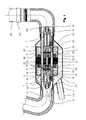
- FIG. 1shows a sectional view of an axial blood pump
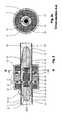
- FIG. 2shows a longitudinal sectional view of an axial delivery device with a magnet bearing, axial stabilization and positioning sensory mechanism
- FIG. 2 ashows a sectional view of the axial delivery device along the line A—A of FIG. 2;
- FIG. 2 bshows a longitudinal sectional view of an axial delivery device with magnetic mounting
- FIG. 2 cshows a sectional view of the axial delivery device along the line A—A of FIG. 2 b;
- FIG. 2 dshows a longitudinal sectional view of an axial delivery device with a conical delivery element
- FIG. 3 ashows a magnetic mounting for an axial delivery device
- FIG. 3 bshows a cross sectional view of the magnetic mounting of FIG. 3 a
- FIG. 4shows a delivery element with double blading
- FIG. 5shows a fluid guide unit with positioning sensor and permanent magnet bearing element
- FIG. 5 ashows a sectional view of the fluid guide unit along the line B—B of FIG. 5;
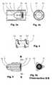
- FIG. 6 ashows a schematical front view of the front face of a rotor hub or hub
- FIG. 6 bshows a schematical front view of the front face of a further rotor hub or hub
- FIG. 6 cshows a schematical front view of the front face of a rotor hub or hub with an eccentric projection
- FIG. 7shows a schematical sectional view of a hub gap, formed between delivery element and hub of a mounting element
- FIG. 7 ashows a schematical sectional view of a hub gap, formed between delivery element and hub of a mounting element
- FIG. 8shows a schematical sectional view through a hub with an axial bore.
- FIG. 1shows an examplanary embodiment of a blood pump according to the invention having a pump housing 3 and a stabilizer housing 2 .
- a motor stator 31 with a motor winding 33is arranged outside and around a tubular hollow body 1 , in which in axial direction the fluid is delivered.
- the motor stator 31drives a delivery element 5 , comprising a motor rotor 32 and a rotor hub 52 and which is supported inside the tubular hollow body 1 .
- the rotor hub 52has a rotor blading 53 .
- In the flow directionin front of and behind the rotor hub fluid guide units 7 , 7 ′ with fluid guide blading 72 , 72 ′ are mounted on the inner wall of the tubular hollow body 1 . Between the fluid guide units 7 , 7 ′ and the rotor hub 52 a so-called hub gap 9 is formed.
- the motor rotor 32combined with the rotor hub 52 , can be rotated via the motor stator 31 .
- the discharged bloodis carried through an elbow 6 to the delivery element 5 and there is rotated by means of the rotor blading 53 , wherein the rotor hub 52 serves for producing advantageous flow dynamical conditions.
- a flow technical advantageous flow against the rotor blading 53is provided by the fluid guide unit 7 ′ with its blading 72 ′ rigidly connected upstream of the hollow body 1 .
- the pressure sensor 60allows a pressure measuring in the inflowing fluid.
- the delivery element 5is in the known way driven by magnetic coupling of the motor rotor 32 with the motor stator 31 . A forming of thrombi in blood as the delivered medium is greatly minimized, as no bearing elements are arranged in the flow, which could cause wake areas, because of the magnetic bearing.
- a vortexing and therewith connected flow lossesonly appear in a small extent.
- a rotor gap 8 between the rotor hub 52 and the inner wall of the hollow body 1has in this case a width, which keeps the flow losses small and at the same time also limits the motor losses, which increase with increasing distance of the motor rotor 32 to the motor stator 31 .
- a width of the rotor gap 8 of between 0.5 to 2.5 mmhas shown to be especially advantageous.
- the bloodleaves the blood pump via the elbow 6 ′ and flows into an aortic cannula 62 , which is attached by means of a releasable connection element 63 on the elbow.
- a specially shielded cable 11 acomprising the supply and signal lines for the motor stator 31 , the axial stabilizer 12 and the sensory mechanism 60 , 61 and 43 , is connected via the cable muff 11 with the blood pump.
- FIGS. 2 and 2 aThe function of the magnetic bearing is described by means of FIGS. 2 and 2 a.
- FIG. 2 and FIG. 2 ashow, furthermore, in the longitudinal sectional view and in the sectional view, respectively, a further embodiment of a blood pump having a magnetically supported rotor hub 52 .
- the motor rotor 32is integrated, having permanent bearing elements 42 arranged at its ends, which are supported in a mounting 4 .
- permanent magnet bearing elements 41are arranged directly opposite permanent magnet bearing elements 42 .
- the permanent magnet bearing elements 41 and 42are charged with an opposed polarity.
- the axially directed attraction force arising between the permanent magnet bearing elements 41 , 42ensures that the delivery element 5 is held coaxially in the tubular hollow body 1 and that radial deflections are correlated.
- Positioning sensors 43also arranged in the fluid guide units 7 and 7 ′, determine the width of the hub gap 9 and measure and control this gap by means of the axial stabilizer 12 .
- the axial stabilizer 12is arranged in a stabilizer housing 2 .
- the axial stabilizers 12formed as windings, produce when the current supply is switched on, a magnetic field, which is transmitted via the stabilizer housing 2 and the flow guide elements 10 in such a way, that the delivery element 5 takes up a stable axial position between the fluid guide units 7 and 7 ′.
- pressure sensors 60At the ends of the fluid guide units 7 and 7 ′, as well as on the outer wall of the tubular hollow body 1 , pressure sensors 60 , as well as a flow sensor 61 for the characterization of the flow are attached.
- the delivery element 5comprised of the motor rotor 32 and the permanent magnet bearing elements 42 , as well as of the rotor blading 53 , is rotated by means of the motor stator 31 . Radial variations during the rotation are levelled-out by the opposingly charged permanent magnet bearing elements, while the axial stabilization is carried out via the positioning sensors 43 and the axial stabilizers 12 .
- the concentration of the main mass of the permanent magnet bearing elements 42 in the area of the axle of the delivery element 5makes it possible to drive the pump in a pulsation operation, e.g. by a fast change of rotational speed of the rotor.
- the permanent magnet bearing elements 41 and 42are alternatively formed as permanent magnet rings also having an axial magnetization instead of as a solid cylinder. Any embodiments, known to the specialist, can be used for the exact design of the permanent magnet bearing elements 41 and 42 .
- an arial stabilizer 12is provided in the embodiment as an example, which interacts with positioning sensors 43 and which acts via the fluid guide units 7 and 7 ′ on the end faces of the delivery element 5 , respectively, and uses an electronic control circuit, not represented in this case.
- the axial stabilizer 12causes an active control of the axial positioning of the delivery element 5 , wherein the stabilizer windings are acted upon by currents according to the carried out control and causes at the same time a magnetic flow, which overlays the axial magnetic flow of the permanent magnet elements and serves for the control of the axial positioning.
- the positioning sensors 43determine variations from the desired axial position of the delivery element 4 and transmit this information to the control circuit.
- FIG. 2 b and FIG. 2 cshow a longitudinal sectional view and a sectional view of a further embodiment of a device according to the invention.
- the supports 74are arranged here for example around the hub 73 at a distance of 90°. In general one support 74 would also be sufficient.
- the mounting 75serves essentially for receiving the permanent magnet bearing elements 41 .
- the opposed permanent magnet bearing elements 41 and 42are also charged with opposing polarity, in this case.
- the positioning sensor 43 and a control electronicare used for the axial stabilization.
- the delivery element 5 and the fluid guide unit 7are formed conical.
- a conical rotor 80 of the delivery element 5expands in flow direction and merges, further conically expanding, in a conical guide unit 81 .
- the permanent magnet bearing elements 41 and 42are charged with opposing polarity.
- the axial stabilizationis also carried out via the positioning sensors 43 in connection with the axial stabilizer 12 .
- FIGS. 3 a and 3 bshow, respectively, a longitudinal sectional view and a sectional view in detail an examplanary embodiment of the mounting 75 with supports 74 .
- FIG. 4shows a delivery element 5 with the rotor hub 52 arranged around the two rotor bladings 53 and 53 ′.
- the arrangement of two or more rotor bladings 53makes it possible, to increase the effect of the blading of the delivery element 5 .
- FIG. 5 and FIG. 5 ashow a longitudinal section view and a sectional view, respectively, of the fluid guide units 7 or 7 ′, respectively, in which the permanent magnet bearing element 41 is surrounded by the positioning sensor 43 .
- FIGS. 6 a, b, c , 7 and 7 aMeasures, which influence the radial pressure distribution and generate compensation flows for the prevention of dead water areas in the area of the rotor hub 52 , i.e. in the hub gap 7 between the front faces of the fluid guide unit 7 and 7 ′ and of the delivery element 5 , are shown in FIGS. 6 a, b, c , 7 and 7 a .
- a rib 723extending radially to the outside from the center, is arranged on a front face 722 of the fluid guide unit 7 , 7 ′.
- the rib 724is formed curve-like.
- ribsinstead of such ribs also convex and/or concave projections, radial bladings, micro-bladings, ribs, recesses and eccentric projections 725 (FIG. 6 c ) of any form on the front face 722 or even simply a roughness of the upper face can be provided.
- theseare means, by which the fluid can be delivered out off the hub gap 9 (compare FIG. 8) at rotation of the delivery element 5 .
- These meanscan, of course, also be arranged on the front face of the rotor hub 52 .
- the representation according to FIG. 7causes advantageously additionally an improvement of the resistance to galling in case of failing of the axial stabilization.
- the hub 73has an axial bore 726 , through which the to be delivered fluid flows and which causes, that the fluid remaining in the hub gap 9 is additionally transported radially.
- magnet bearing according to the inventionis not limited to cylindrical forms of the magnets. Other geometric designs of the permanent magnet bearing elements 41 and 42 are possible.
Landscapes
- Engineering & Computer Science (AREA)
- Health & Medical Sciences (AREA)
- Heart & Thoracic Surgery (AREA)
- Mechanical Engineering (AREA)
- General Engineering & Computer Science (AREA)
- Cardiology (AREA)
- Anesthesiology (AREA)
- Biomedical Technology (AREA)
- Life Sciences & Earth Sciences (AREA)
- Animal Behavior & Ethology (AREA)
- General Health & Medical Sciences (AREA)
- Public Health (AREA)
- Veterinary Medicine (AREA)
- Hematology (AREA)
- Power Engineering (AREA)
- Physics & Mathematics (AREA)
- Fluid Mechanics (AREA)
- Electromagnetism (AREA)
- External Artificial Organs (AREA)
- Structures Of Non-Positive Displacement Pumps (AREA)
- Reciprocating Pumps (AREA)
Abstract
Description
Claims (13)
Applications Claiming Priority (4)
| Application Number | Priority Date | Filing Date | Title |
|---|---|---|---|
| DE19918841 | 1999-04-20 | ||
| DE19918841 | 1999-04-20 | ||
| DE19944863ADE19944863A1 (en) | 1999-09-18 | 1999-09-18 | Device for careful delivery of single- or multiphase fluids incorporates tubular cavity to guide fluids and electric motor's rotor acting as rotating delivery device with axial alignment mounted inside tubular cavity |
| PCT/EP2000/003563WO2000064030A1 (en) | 1999-04-20 | 2000-04-19 | Device for delivering single-phase or multiphase fluids without altering the properties thereof |
Publications (1)
| Publication Number | Publication Date |
|---|---|
| US6742999B1true US6742999B1 (en) | 2004-06-01 |
Family
ID=26053083
Family Applications (1)
| Application Number | Title | Priority Date | Filing Date |
|---|---|---|---|
| US09/959,043Expired - LifetimeUS6742999B1 (en) | 1999-04-20 | 2000-04-19 | Device for delivering single-phase or multiphase fluids without altering the properties thereof |
Country Status (9)
| Country | Link |
|---|---|
| US (1) | US6742999B1 (en) |
| EP (1) | EP1208630B1 (en) |
| JP (1) | JP3610305B2 (en) |
| CN (1) | CN1245793C (en) |
| AT (1) | ATE256931T1 (en) |
| AU (1) | AU757839B2 (en) |
| CA (1) | CA2369955C (en) |
| RU (1) | RU2266141C2 (en) |
| WO (1) | WO2000064030A1 (en) |
Cited By (36)
| Publication number | Priority date | Publication date | Assignee | Title |
|---|---|---|---|---|
| US20040116776A1 (en)* | 2001-02-16 | 2004-06-17 | Peter Nuesser | Device for axially conveying body fluids |
| NL1028471C2 (en)* | 2005-03-07 | 2006-09-11 | Hemodynamics Holding B V | Pump for vulnerable fluid, use of such pump for pumping blood. |
| WO2007105842A1 (en)* | 2006-03-15 | 2007-09-20 | Korea University Industrial & Academic Collaboration Foundation | Rotary blood pump |
| US20070297923A1 (en)* | 2006-06-23 | 2007-12-27 | Terumo Kabushiki Kaisha | Blood pump device |
| US20080009837A1 (en)* | 2003-10-02 | 2008-01-10 | Medtronic, Inc. | Pressure sensing in implantable medical devices |
| KR100805268B1 (en) | 2006-04-18 | 2008-02-25 | 고려대학교 산학협력단 | Rotary Blood Pump |
| AU2006230718B2 (en)* | 2001-02-16 | 2008-09-25 | Berlin Heart Gmbh | Device for axially conveying body fluids |
| US20080243074A1 (en)* | 2007-03-30 | 2008-10-02 | Miesel Keith A | Catheter malfunction determinations using physiologic pressure |
| US20090112312A1 (en)* | 2007-02-26 | 2009-04-30 | Larose Jeffrey A | Intravascular ventricular assist device |
| US20090259308A1 (en)* | 2005-09-13 | 2009-10-15 | Tatsuya Hidaka | Artificial heart pump |
| US20100069841A1 (en)* | 2003-10-02 | 2010-03-18 | Medtronic, Inc. | Determining catheter status |
| US20100168607A1 (en)* | 2003-10-02 | 2010-07-01 | Medtronic, Inc. | Determining catheter status |
| US20100222632A1 (en)* | 2009-02-27 | 2010-09-02 | Victor Poirier | Prevention of aortic valve fusion |
| US20100222633A1 (en)* | 2009-02-27 | 2010-09-02 | Victor Poirier | Blood pump system with controlled weaning |
| WO2010099287A1 (en)* | 2009-02-27 | 2010-09-02 | Thoratec Corporation | Blood pump system with arterial pressure monitoring |
| US20100222635A1 (en)* | 2009-02-27 | 2010-09-02 | Thoratec Corporation | Maximizing blood pump flow while avoiding left ventricle collapse |
| US20100222634A1 (en)* | 2009-02-27 | 2010-09-02 | Thoratec Corporation | Blood flow meter |
| US8317770B2 (en) | 2006-04-06 | 2012-11-27 | Medtronic, Inc. | Systems and methods of identifying catheter malfunctions using pressure sensing |
| US20140341726A1 (en)* | 2013-05-14 | 2014-11-20 | Heartware, Inc. | Blood pump with separate mixed-flow and axial-flow impeller stages and multi-stage stators |
| US9044537B2 (en) | 2007-03-30 | 2015-06-02 | Medtronic, Inc. | Devices and methods for detecting catheter complications |
| US9155827B2 (en) | 2010-02-17 | 2015-10-13 | Flow Forward Medical, Inc. | System and method to increase the overall diameter of veins |
| US9339598B2 (en) | 2005-10-05 | 2016-05-17 | Heartware, Inc. | Axial flow pump with multi-grooved rotor |
| US9433717B2 (en) | 2010-09-24 | 2016-09-06 | Thoratec Corporation | Generating artificial pulse |
| US9539380B2 (en) | 2011-08-17 | 2017-01-10 | Flow Forward Medical, Inc. | System and method to increase the overall diameter of veins and arteries |
| US9555174B2 (en) | 2010-02-17 | 2017-01-31 | Flow Forward Medical, Inc. | Blood pump systems and methods |
| US9577494B2 (en) | 2011-03-23 | 2017-02-21 | Nuovo Pignone Spa | Elastic cone for sealing and method |
| US9662431B2 (en) | 2010-02-17 | 2017-05-30 | Flow Forward Medical, Inc. | Blood pump systems and methods |
| US9694123B2 (en) | 2014-04-15 | 2017-07-04 | Tc1 Llc | Methods and systems for controlling a blood pump |
| US9757502B2 (en) | 2010-09-24 | 2017-09-12 | Tci Llc | Control of circulatory assist systems |
| WO2017196271A1 (en) | 2016-05-13 | 2017-11-16 | Koc Universitesi | Internal axial flow blood pump with passive magnets and hydrodynamic radial bearing |
| WO2019033012A1 (en)* | 2017-08-11 | 2019-02-14 | Antaki James F | Blood-immersed bearing system for a blood pump |
| US10258730B2 (en) | 2012-08-17 | 2019-04-16 | Flow Forward Medical, Inc. | Blood pump systems and methods |
| US10426878B2 (en) | 2011-08-17 | 2019-10-01 | Flow Forward Medical, Inc. | Centrifugal blood pump systems |
| CN111372618A (en)* | 2017-09-21 | 2020-07-03 | 好心公司 | Turbine with internal buckets |
| US11421694B2 (en)* | 2019-02-01 | 2022-08-23 | White Knight Fluid Handling Inc. | Pump having magnets for journaling and magnetically axially positioning rotor thereof, and related methods |
| US11534593B2 (en) | 2016-04-29 | 2022-12-27 | Artio Medical, Inc. | Conduit tips and systems and methods for use |
Families Citing this family (23)
| Publication number | Priority date | Publication date | Assignee | Title |
|---|---|---|---|---|
| DE10108810A1 (en)* | 2001-02-16 | 2002-08-29 | Berlin Heart Ag | Device for the axial conveyance of liquids |
| DE10164942B4 (en)* | 2001-02-16 | 2014-04-30 | Berlin Heart Gmbh | Device for axially conveying body fluids comprises inflow and outflow regions with correponding tube bends whose cross sections diminish in a specified manner |
| DE10164898B4 (en)* | 2001-04-30 | 2010-09-23 | Berlin Heart Gmbh | Method for controlling a support pump for pulsatile pressure fluid delivery systems |
| DE10123138B4 (en) | 2001-04-30 | 2007-09-27 | Berlin Heart Ag | Method for position control of a permanently magnetically mounted rotating component |
| DE10216421A1 (en) | 2002-04-12 | 2003-10-30 | Forschungszentrum Juelich Gmbh | Magnetic guiding device |
| JP4108054B2 (en) | 2003-04-30 | 2008-06-25 | 三菱重工業株式会社 | Artificial heart pump |
| US20040241019A1 (en)* | 2003-05-28 | 2004-12-02 | Michael Goldowsky | Passive non-contacting smart bearing suspension for turbo blood-pumps |
| JP4611364B2 (en)* | 2007-11-26 | 2011-01-12 | 三菱重工業株式会社 | Artificial heart pump |
| JP4523961B2 (en)* | 2007-11-26 | 2010-08-11 | 三菱重工業株式会社 | Artificial heart pump |
| EP2319552B1 (en) | 2009-11-06 | 2014-01-08 | Berlin Heart GmbH | Blood pump |
| CN103635210A (en) | 2011-05-05 | 2014-03-12 | 柏林心脏有限公司 | Blood pump |
| CN103195758B (en)* | 2013-04-07 | 2015-06-10 | 江苏大学 | Inlet device for measuring axial flow pump impeller inlet cross section particle image velocimetry (PIV) flow field |
| DE102013211848A1 (en) | 2013-06-21 | 2014-12-24 | Heraeus Precious Metals Gmbh & Co. Kg | Pump housing made of at least two different sinterable materials |
| DE102013211844A1 (en) | 2013-06-21 | 2014-12-24 | Heraeus Precious Metals Gmbh & Co. Kg | Pump housing made of a magnetic and a non-magnetic material |
| DE102014004121A1 (en) | 2014-03-24 | 2015-09-24 | Heraeus Deutschland GmbH & Co. KG | Pump housing made of at least three different sinterable materials |
| EP3115069A1 (en) | 2015-07-07 | 2017-01-11 | Berlin Heart GmbH | Device for determining the position of a movable component |
| RU2629054C1 (en)* | 2016-08-10 | 2017-08-24 | Федеральное государственное бюджетное учреждение "Национальный исследовательский центр "Курчатовский институт" | Axial pump of auxiliary circulation |
| RU2637605C1 (en)* | 2016-11-09 | 2017-12-05 | Алексей Васильевич Коротеев | Microaxial pump for circulation maintenance (versions) |
| CN107013470B (en)* | 2017-06-05 | 2019-02-05 | 兰州理工大学 | A kind of axial-flow pump |
| CN107546440A (en)* | 2017-09-25 | 2018-01-05 | 青岛金立磁性材料有限公司 | A kind of plastic magnetic rotor group for the cooling of electric bus battery pack |
| EP3574932A1 (en)* | 2018-05-28 | 2019-12-04 | Berlin Heart GmbH | Blood pump |
| FR3126565A1 (en)* | 2021-08-30 | 2023-03-03 | Fondation Hôpital Saint Joseph | ASSEMBLY COMPRISING A PORTABLE CENTRIFUGAL PUMP AND AN ELECTROMAGNETIC MOTOR |
| CN115105742A (en)* | 2022-06-29 | 2022-09-27 | 利为惠德无锡医疗科技有限公司 | Outlet elbow of an implantable artificial heart and artificial heart |
Citations (27)
| Publication number | Priority date | Publication date | Assignee | Title |
|---|---|---|---|---|
| US3512851A (en) | 1968-12-11 | 1970-05-19 | Halliburton Co | Magnetic bearing |
| US3614181A (en) | 1970-07-02 | 1971-10-19 | Us Air Force | Magnetic bearing for combined radial and thrust loads |
| US3623835A (en) | 1969-06-11 | 1971-11-30 | Halliburton Co | Gas flowmeter |
| US4057369A (en) | 1973-07-21 | 1977-11-08 | Maschinenfabrik Augsburg-Nurnberg Ag | Vacuum pump having a rotor supported in the interior of its casing |
| GB2057590A (en) | 1979-07-02 | 1981-04-01 | United Gas Industries Ltd | Magnetic Balancing of Bearings |
| US4398773A (en)* | 1979-05-12 | 1983-08-16 | Kernforschungsanlage Julich Gesellschaft Mit Beschrankter Haftung | Magnetic suspension assembly for a rotor |
| US4643641A (en)* | 1984-09-10 | 1987-02-17 | Mici Limited Partnership Iv | Method and apparatus for sterilization of a centrifugal pump |
| US4688998A (en) | 1981-03-18 | 1987-08-25 | Olsen Don B | Magnetically suspended and rotated impellor pump apparatus and method |
| US4763032A (en)* | 1983-11-29 | 1988-08-09 | Fraunhofer-Gesellschaft Zur Forderung Der Angewandten Forschung E.V. | Magnetic rotor bearing |
| US4779614A (en)* | 1987-04-09 | 1988-10-25 | Nimbus Medical, Inc. | Magnetically suspended rotor axial flow blood pump |
| US4812694A (en) | 1974-09-12 | 1989-03-14 | Kernforschungsanlage Julich Gesellschaft Mit Beschrankter Haftung | Contact free magnetic bearing |
| US4948348A (en) | 1987-05-07 | 1990-08-14 | Robert Doll | Immersion pump, especially for low-boiling fluids |
| US4957504A (en) | 1988-12-02 | 1990-09-18 | Chardack William M | Implantable blood pump |
| US5112200A (en) | 1990-05-29 | 1992-05-12 | Nu-Tech Industries, Inc. | Hydrodynamically suspended rotor axial flow blood pump |
| US5126610A (en) | 1988-03-12 | 1992-06-30 | Kernforschungsanlage Julich Gesellschaft Mit Beschrankter Haftung | Axially stabilized magnetic bearing having a permanently magnetized radial bearing |
| US5180287A (en)* | 1990-03-15 | 1993-01-19 | Abbott Laboratories | Method for monitoring fluid flow from a volumetric pump |
| US5211546A (en)* | 1990-05-29 | 1993-05-18 | Nu-Tech Industries, Inc. | Axial flow blood pump with hydrodynamically suspended rotor |
| US5385581A (en) | 1982-04-04 | 1995-01-31 | Life Extenders Corporation | Magnetically suspended and rotated rotor |
| US5635784A (en) | 1995-02-13 | 1997-06-03 | Seale; Joseph B. | Bearingless ultrasound-sweep rotor |
| US5695471A (en) | 1996-02-20 | 1997-12-09 | Kriton Medical, Inc. | Sealless rotary blood pump with passive magnetic radial bearings and blood immersed axial bearings |
| WO1997049440A2 (en) | 1996-06-26 | 1997-12-31 | University Of Pittsburgh | Magnetically suspended miniature fluid pump and method of making the same |
| WO1998011650A1 (en) | 1996-09-10 | 1998-03-19 | Sulzer Electronics Ag | Rotary pump and process to operate it |
| EP0847767A1 (en) | 1996-12-13 | 1998-06-17 | Micromed Technology, Inc. | Rotary blood pump |
| WO1998028543A2 (en) | 1996-12-23 | 1998-07-02 | Nuesser Peter | Device for feeding single-phase and polyphase fluids |
| EP0856666A1 (en) | 1997-01-31 | 1998-08-05 | Ebara Corporation | Liquid delivery device, method of controlling such liquid delivery device, and liquid delivery pump |
| US6201329B1 (en)* | 1997-10-27 | 2001-03-13 | Mohawk Innovative Technology, Inc. | Pump having magnetic bearing for pumping blood and the like |
| US6527699B1 (en)* | 2000-06-02 | 2003-03-04 | Michael P. Goldowsky | Magnetic suspension blood pump |
Family Cites Families (6)
| Publication number | Priority date | Publication date | Assignee | Title |
|---|---|---|---|---|
| JPS59228848A (en)* | 1983-06-10 | 1984-12-22 | 三菱プレシジヨン株式会社 | Artificial heart |
| US5707218A (en)* | 1995-04-19 | 1998-01-13 | Nimbus, Inc. | Implantable electric axial-flow blood pump with blood cooled bearing |
| RU2115439C1 (en)* | 1996-09-30 | 1998-07-20 | Научно-исследовательский институт трансплантологии и искусственных органов МЗ и МП РФ | Artificial heart ventricle |
| ES2227718T3 (en)* | 1996-10-04 | 2005-04-01 | United States Surgical Corporation | CIRCULATORY SUPPORT SYSTEM. |
| US5928131A (en)* | 1997-11-26 | 1999-07-27 | Vascor, Inc. | Magnetically suspended fluid pump and control system |
| ES2215044T3 (en)* | 1999-04-20 | 2004-10-01 | Forschungszentrum Julich Gmbh | ROTOR DEVICE. |
- 2000
- 2000-04-19EPEP00927001Apatent/EP1208630B1/ennot_activeExpired - Lifetime
- 2000-04-19CACA002369955Apatent/CA2369955C/ennot_activeExpired - Fee Related
- 2000-04-19RURU2001131346/14Apatent/RU2266141C2/ennot_activeIP Right Cessation
- 2000-04-19USUS09/959,043patent/US6742999B1/ennot_activeExpired - Lifetime
- 2000-04-19CNCNB008065519Apatent/CN1245793C/ennot_activeExpired - Fee Related
- 2000-04-19JPJP2000613058Apatent/JP3610305B2/ennot_activeExpired - Fee Related
- 2000-04-19AUAU45534/00Apatent/AU757839B2/ennot_activeCeased
- 2000-04-19WOPCT/EP2000/003563patent/WO2000064030A1/enactiveIP Right Grant
- 2000-04-19ATAT00927001Tpatent/ATE256931T1/ennot_activeIP Right Cessation
Patent Citations (31)
| Publication number | Priority date | Publication date | Assignee | Title |
|---|---|---|---|---|
| US3512851A (en) | 1968-12-11 | 1970-05-19 | Halliburton Co | Magnetic bearing |
| US3623835A (en) | 1969-06-11 | 1971-11-30 | Halliburton Co | Gas flowmeter |
| US3614181A (en) | 1970-07-02 | 1971-10-19 | Us Air Force | Magnetic bearing for combined radial and thrust loads |
| US4057369A (en) | 1973-07-21 | 1977-11-08 | Maschinenfabrik Augsburg-Nurnberg Ag | Vacuum pump having a rotor supported in the interior of its casing |
| US4812694A (en) | 1974-09-12 | 1989-03-14 | Kernforschungsanlage Julich Gesellschaft Mit Beschrankter Haftung | Contact free magnetic bearing |
| US4398773A (en)* | 1979-05-12 | 1983-08-16 | Kernforschungsanlage Julich Gesellschaft Mit Beschrankter Haftung | Magnetic suspension assembly for a rotor |
| GB2057590A (en) | 1979-07-02 | 1981-04-01 | United Gas Industries Ltd | Magnetic Balancing of Bearings |
| US4688998A (en) | 1981-03-18 | 1987-08-25 | Olsen Don B | Magnetically suspended and rotated impellor pump apparatus and method |
| US5385581A (en) | 1982-04-04 | 1995-01-31 | Life Extenders Corporation | Magnetically suspended and rotated rotor |
| US4763032A (en)* | 1983-11-29 | 1988-08-09 | Fraunhofer-Gesellschaft Zur Forderung Der Angewandten Forschung E.V. | Magnetic rotor bearing |
| US4643641A (en)* | 1984-09-10 | 1987-02-17 | Mici Limited Partnership Iv | Method and apparatus for sterilization of a centrifugal pump |
| US4779614A (en)* | 1987-04-09 | 1988-10-25 | Nimbus Medical, Inc. | Magnetically suspended rotor axial flow blood pump |
| US4948348A (en) | 1987-05-07 | 1990-08-14 | Robert Doll | Immersion pump, especially for low-boiling fluids |
| US5126610A (en) | 1988-03-12 | 1992-06-30 | Kernforschungsanlage Julich Gesellschaft Mit Beschrankter Haftung | Axially stabilized magnetic bearing having a permanently magnetized radial bearing |
| US4957504A (en) | 1988-12-02 | 1990-09-18 | Chardack William M | Implantable blood pump |
| US5180287A (en)* | 1990-03-15 | 1993-01-19 | Abbott Laboratories | Method for monitoring fluid flow from a volumetric pump |
| US5211546A (en)* | 1990-05-29 | 1993-05-18 | Nu-Tech Industries, Inc. | Axial flow blood pump with hydrodynamically suspended rotor |
| US5112200A (en) | 1990-05-29 | 1992-05-12 | Nu-Tech Industries, Inc. | Hydrodynamically suspended rotor axial flow blood pump |
| US5947892A (en) | 1993-11-10 | 1999-09-07 | Micromed Technology, Inc. | Rotary blood pump |
| US5635784A (en) | 1995-02-13 | 1997-06-03 | Seale; Joseph B. | Bearingless ultrasound-sweep rotor |
| US5695471A (en) | 1996-02-20 | 1997-12-09 | Kriton Medical, Inc. | Sealless rotary blood pump with passive magnetic radial bearings and blood immersed axial bearings |
| US6015272A (en)* | 1996-06-26 | 2000-01-18 | University Of Pittsburgh | Magnetically suspended miniature fluid pump and method of designing the same |
| WO1997049440A2 (en) | 1996-06-26 | 1997-12-31 | University Of Pittsburgh | Magnetically suspended miniature fluid pump and method of making the same |
| WO1998011650A1 (en) | 1996-09-10 | 1998-03-19 | Sulzer Electronics Ag | Rotary pump and process to operate it |
| US6053705A (en) | 1996-09-10 | 2000-04-25 | Sulzer Electronics Ag | Rotary pump and process to operate it |
| EP0847767A1 (en) | 1996-12-13 | 1998-06-17 | Micromed Technology, Inc. | Rotary blood pump |
| WO1998028543A2 (en) | 1996-12-23 | 1998-07-02 | Nuesser Peter | Device for feeding single-phase and polyphase fluids |
| EP0856666A1 (en) | 1997-01-31 | 1998-08-05 | Ebara Corporation | Liquid delivery device, method of controlling such liquid delivery device, and liquid delivery pump |
| US6092994A (en) | 1997-01-31 | 2000-07-25 | Ebara Corporation | Liquid delivery device, method of controlling such liquid delivery device, and liquid delivery pump |
| US6201329B1 (en)* | 1997-10-27 | 2001-03-13 | Mohawk Innovative Technology, Inc. | Pump having magnetic bearing for pumping blood and the like |
| US6527699B1 (en)* | 2000-06-02 | 2003-03-04 | Michael P. Goldowsky | Magnetic suspension blood pump |
Non-Patent Citations (1)
| Title |
|---|
| Kawahito et al.: In Phase 1 Ex Vivo Studies of the Baylor/NASA Axial Flow Venticular Assist Device, in: Heart Replacement Artificial Heart 5, pp. 245-252, Springer Verlag Tokyo 196, Publisher T. Akutso and H. Koyagani. |
Cited By (77)
| Publication number | Priority date | Publication date | Assignee | Title |
|---|---|---|---|---|
| US20040116776A1 (en)* | 2001-02-16 | 2004-06-17 | Peter Nuesser | Device for axially conveying body fluids |
| AU2006230718B2 (en)* | 2001-02-16 | 2008-09-25 | Berlin Heart Gmbh | Device for axially conveying body fluids |
| US7374574B2 (en)* | 2001-02-16 | 2008-05-20 | Berlin Heart Gmbh | Device for axially conveying body fluids |
| US9138537B2 (en) | 2003-10-02 | 2015-09-22 | Medtronic, Inc. | Determining catheter status |
| US20080009837A1 (en)* | 2003-10-02 | 2008-01-10 | Medtronic, Inc. | Pressure sensing in implantable medical devices |
| US10357620B2 (en) | 2003-10-02 | 2019-07-23 | Medtronic, Inc. | Determining catheter status |
| US7955319B2 (en) | 2003-10-02 | 2011-06-07 | Medtronic, Inc. | Pressure sensing in implantable medical devices |
| US9033920B2 (en) | 2003-10-02 | 2015-05-19 | Medtronic, Inc. | Determining catheter status |
| US20110208163A1 (en)* | 2003-10-02 | 2011-08-25 | Medtronic, Inc. | Pressure Sensing in Implantable Medical Devices |
| US20100069841A1 (en)* | 2003-10-02 | 2010-03-18 | Medtronic, Inc. | Determining catheter status |
| US20100168607A1 (en)* | 2003-10-02 | 2010-07-01 | Medtronic, Inc. | Determining catheter status |
| US9956332B2 (en) | 2004-12-03 | 2018-05-01 | Heartware, Inc. | Axial flow pump with multi-grooved rotor |
| WO2006096049A1 (en)* | 2005-03-07 | 2006-09-14 | Hemodynamics Holding B.V. | Pump for a delicate fluid, use of such a pump for pumping blood |
| NL1028471C2 (en)* | 2005-03-07 | 2006-09-11 | Hemodynamics Holding B V | Pump for vulnerable fluid, use of such pump for pumping blood. |
| US20090259308A1 (en)* | 2005-09-13 | 2009-10-15 | Tatsuya Hidaka | Artificial heart pump |
| US8157539B2 (en) | 2005-09-13 | 2012-04-17 | Mitsubishi Heavy Industries, Ltd. | Artificial heart pump |
| US10251985B2 (en) | 2005-10-05 | 2019-04-09 | Heartware, Inc. | Axial flow pump with multi-grooved rotor |
| US9737652B2 (en) | 2005-10-05 | 2017-08-22 | Heartware, Inc. | Axial flow pump with multi-grooved rotor |
| US9339598B2 (en) | 2005-10-05 | 2016-05-17 | Heartware, Inc. | Axial flow pump with multi-grooved rotor |
| WO2007105842A1 (en)* | 2006-03-15 | 2007-09-20 | Korea University Industrial & Academic Collaboration Foundation | Rotary blood pump |
| US8317770B2 (en) | 2006-04-06 | 2012-11-27 | Medtronic, Inc. | Systems and methods of identifying catheter malfunctions using pressure sensing |
| KR100805268B1 (en) | 2006-04-18 | 2008-02-25 | 고려대학교 산학협력단 | Rotary Blood Pump |
| US20070297923A1 (en)* | 2006-06-23 | 2007-12-27 | Terumo Kabushiki Kaisha | Blood pump device |
| US8043074B2 (en) | 2006-06-23 | 2011-10-25 | Terumo Kabushiki Kaisha | Blood pump device |
| US10251986B2 (en) | 2007-02-26 | 2019-04-09 | Heartware, Inc. | Intravascular ventricular assist device |
| US10052421B2 (en) | 2007-02-26 | 2018-08-21 | Heartware, Inc. | Intravascular ventricular assist device |
| US9579433B2 (en) | 2007-02-26 | 2017-02-28 | Heartware, Inc. | Intravascular ventricular assist device |
| US8641594B2 (en) | 2007-02-26 | 2014-02-04 | Heartware, Inc. | Intravascular ventricular assist device |
| US20090112312A1 (en)* | 2007-02-26 | 2009-04-30 | Larose Jeffrey A | Intravascular ventricular assist device |
| US9895476B2 (en) | 2007-02-26 | 2018-02-20 | Heartware, Inc. | Intravascular ventricular assist device |
| US20080243074A1 (en)* | 2007-03-30 | 2008-10-02 | Miesel Keith A | Catheter malfunction determinations using physiologic pressure |
| US9044537B2 (en) | 2007-03-30 | 2015-06-02 | Medtronic, Inc. | Devices and methods for detecting catheter complications |
| US8323244B2 (en) | 2007-03-30 | 2012-12-04 | Medtronic, Inc. | Catheter malfunction determinations using physiologic pressure |
| US20100222878A1 (en)* | 2009-02-27 | 2010-09-02 | Thoratec Corporation | Blood pump system with arterial pressure monitoring |
| US8562507B2 (en) | 2009-02-27 | 2013-10-22 | Thoratec Corporation | Prevention of aortic valve fusion |
| US11648386B2 (en) | 2009-02-27 | 2023-05-16 | Tc1 Llc | Prevention of aortic valve fusion |
| US8715151B2 (en) | 2009-02-27 | 2014-05-06 | Thoratec Corporation | Blood flow meter |
| US20100222632A1 (en)* | 2009-02-27 | 2010-09-02 | Victor Poirier | Prevention of aortic valve fusion |
| US12083330B2 (en) | 2009-02-27 | 2024-09-10 | Tc1 Llc | Prevention of aortic valve fusion |
| US20100222633A1 (en)* | 2009-02-27 | 2010-09-02 | Victor Poirier | Blood pump system with controlled weaning |
| US10376622B2 (en) | 2009-02-27 | 2019-08-13 | Tc1 Llc | Prevention of aortic valve fusion |
| WO2010099287A1 (en)* | 2009-02-27 | 2010-09-02 | Thoratec Corporation | Blood pump system with arterial pressure monitoring |
| US9687596B2 (en) | 2009-02-27 | 2017-06-27 | Tci Llc | Prevention of aortic valve fusion |
| US8449444B2 (en) | 2009-02-27 | 2013-05-28 | Thoratec Corporation | Blood flow meter |
| US20100222634A1 (en)* | 2009-02-27 | 2010-09-02 | Thoratec Corporation | Blood flow meter |
| US10046098B2 (en) | 2009-02-27 | 2018-08-14 | Tc1 Llc | Prevention of aortic valve fusion |
| US20100222635A1 (en)* | 2009-02-27 | 2010-09-02 | Thoratec Corporation | Maximizing blood pump flow while avoiding left ventricle collapse |
| US10293089B2 (en) | 2010-02-17 | 2019-05-21 | Flow Forward Medical, Inc. | System and method to increase the overall diameter of veins |
| US9155827B2 (en) | 2010-02-17 | 2015-10-13 | Flow Forward Medical, Inc. | System and method to increase the overall diameter of veins |
| US10537674B2 (en) | 2010-02-17 | 2020-01-21 | Flow Forward Medical, Inc. | System and method to increase the overall diameter of veins |
| US9555174B2 (en) | 2010-02-17 | 2017-01-31 | Flow Forward Medical, Inc. | Blood pump systems and methods |
| US10376629B2 (en) | 2010-02-17 | 2019-08-13 | Flow Forward Medical, Inc. | Methods to increase the overall diameter of donating veins and arteries |
| US9662431B2 (en) | 2010-02-17 | 2017-05-30 | Flow Forward Medical, Inc. | Blood pump systems and methods |
| US11724018B2 (en) | 2010-02-17 | 2023-08-15 | Artio Medical, Inc. | System and method to increase the overall diameter of veins |
| US11944799B2 (en) | 2010-09-24 | 2024-04-02 | Tc1 Llc | Generating artificial pulse |
| US10086122B2 (en) | 2010-09-24 | 2018-10-02 | Tc1 Llc | Generating artificial pulse |
| US10881772B2 (en) | 2010-09-24 | 2021-01-05 | Tc1 Llc | Generating artificial pulse |
| US9757502B2 (en) | 2010-09-24 | 2017-09-12 | Tci Llc | Control of circulatory assist systems |
| US9801988B2 (en) | 2010-09-24 | 2017-10-31 | Tc1 Llc | Generating artificial pulse |
| US9433717B2 (en) | 2010-09-24 | 2016-09-06 | Thoratec Corporation | Generating artificial pulse |
| US9577494B2 (en) | 2011-03-23 | 2017-02-21 | Nuovo Pignone Spa | Elastic cone for sealing and method |
| US10426878B2 (en) | 2011-08-17 | 2019-10-01 | Flow Forward Medical, Inc. | Centrifugal blood pump systems |
| US9539380B2 (en) | 2011-08-17 | 2017-01-10 | Flow Forward Medical, Inc. | System and method to increase the overall diameter of veins and arteries |
| US11400275B2 (en) | 2011-08-17 | 2022-08-02 | Artio Medical, Inc. | Blood pump system for causing persistent increase in the overall diameter of a target vessel |
| US10258730B2 (en) | 2012-08-17 | 2019-04-16 | Flow Forward Medical, Inc. | Blood pump systems and methods |
| US11160914B2 (en) | 2012-08-17 | 2021-11-02 | Artio Medical, Inc. | Blood pump systems and methods |
| US10111994B2 (en)* | 2013-05-14 | 2018-10-30 | Heartware, Inc. | Blood pump with separate mixed-flow and axial-flow impeller stages and multi-stage stators |
| US10434232B2 (en) | 2013-05-14 | 2019-10-08 | Heartware, Inc. | Blood pump with separate mixed-flow and axial-flow impeller stages and multi-stage stators |
| US20140341726A1 (en)* | 2013-05-14 | 2014-11-20 | Heartware, Inc. | Blood pump with separate mixed-flow and axial-flow impeller stages and multi-stage stators |
| US9694123B2 (en) | 2014-04-15 | 2017-07-04 | Tc1 Llc | Methods and systems for controlling a blood pump |
| US11534593B2 (en) | 2016-04-29 | 2022-12-27 | Artio Medical, Inc. | Conduit tips and systems and methods for use |
| WO2017196271A1 (en) | 2016-05-13 | 2017-11-16 | Koc Universitesi | Internal axial flow blood pump with passive magnets and hydrodynamic radial bearing |
| WO2019033012A1 (en)* | 2017-08-11 | 2019-02-14 | Antaki James F | Blood-immersed bearing system for a blood pump |
| US11672968B2 (en) | 2017-08-11 | 2023-06-13 | Carnegie Mellon University | Blood-immersed bearing system for a blood pump |
| CN111372618A (en)* | 2017-09-21 | 2020-07-03 | 好心公司 | Turbine with internal buckets |
| US11421694B2 (en)* | 2019-02-01 | 2022-08-23 | White Knight Fluid Handling Inc. | Pump having magnets for journaling and magnetically axially positioning rotor thereof, and related methods |
| US12012965B2 (en)* | 2019-02-01 | 2024-06-18 | White Knight Fluid Handling Inc. | Pump having opposing magnets between a rotor and stator, and related assemblies, systems, and methods |
Also Published As
| Publication number | Publication date |
|---|---|
| CA2369955C (en) | 2005-10-18 |
| CA2369955A1 (en) | 2000-10-26 |
| RU2001131346A (en) | 2003-08-10 |
| CN1348624A (en) | 2002-05-08 |
| JP3610305B2 (en) | 2005-01-12 |
| ATE256931T1 (en) | 2004-01-15 |
| EP1208630A1 (en) | 2002-05-29 |
| JP2003525069A (en) | 2003-08-26 |
| WO2000064030A1 (en) | 2000-10-26 |
| EP1208630B1 (en) | 2003-12-17 |
| RU2266141C2 (en) | 2005-12-20 |
| AU4553400A (en) | 2000-11-02 |
| AU757839B2 (en) | 2003-03-06 |
| CN1245793C (en) | 2006-03-15 |
Similar Documents
| Publication | Publication Date | Title |
|---|---|---|
| US6742999B1 (en) | Device for delivering single-phase or multiphase fluids without altering the properties thereof | |
| US11883641B2 (en) | Axial flow blood pump | |
| US12383725B2 (en) | Bearingless implantable blood pump | |
| CN110709114B (en) | Cardiac pump driver and bearing | |
| JP2006525460A (en) | Fluid pump | |
| JP2004522894A (en) | Equipment for axial transport of liquids | |
| CA2253435C (en) | Hybrid magnetically suspended and rotated centrifugal pumping apparatus and method | |
| US7972122B2 (en) | Multiple rotor, wide blade, axial flow pump | |
| JP4390856B2 (en) | Rotary pump and driving method thereof | |
| EP1481699A1 (en) | Passive non-contacting smart bearing suspension for turbo blood-pumps | |
| WO2006053384A1 (en) | Fluid pump | |
| US20060122456A1 (en) | Wide blade, axial flow pump | |
| KR20080085911A (en) | Rotary blood pump | |
| CN108175884A (en) | Heart chamber auxiliary pump | |
| EP1235983A4 (en) | ELECTROMAGNETICALLY STORED AND DRIVEN PUMP | |
| DE20007580U1 (en) | Device for the gentle delivery of single or multi-phase fluids | |
| Qian et al. | Permanent magnetic-levitation of rotating impeller: a decisive breakthrough in the centrifugal pump | |
| Shinshi et al. | Development of extracorporeal maglev blood pumps | |
| EP1415672B1 (en) | Pump with pressure sensor | |
| Shinshi | Ventricular Assist Devices Utilizing Magnetic Bearing Systems | |
| Qian | Gyro-effect Stabilizes Unstable Permanent Maglev Centrifugal Pump | |
| ES2370500T3 (en) | BOMB. | |
| CN119455246A (en) | A magnetically suspended dual-core auxiliary device |
Legal Events
| Date | Code | Title | Description |
|---|---|---|---|
| AS | Assignment | Owner name:BERLIN HEART AG, GERMANY Free format text:ASSIGNMENT OF ASSIGNORS INTEREST;ASSIGNORS:NUSSER, PETER;MULLER, JOHANNES;PETERS, HANS-ERHARD;REEL/FRAME:012504/0301 Effective date:20011025 | |
| AS | Assignment | Owner name:BERLIN HEART AG, GERMANY Free format text:ASSIGNMENT OF ASSIGNORS INTEREST;ASSIGNOR:BERLIN HEART AG;REEL/FRAME:014278/0878 Effective date:20040116 Owner name:FORSCHUNGSZENTRUM JULICH GMBH, GERMANY Free format text:ASSIGNMENT OF ASSIGNORS INTEREST;ASSIGNOR:BERLIN HEART AG;REEL/FRAME:014278/0878 Effective date:20040116 | |
| STCF | Information on status: patent grant | Free format text:PATENTED CASE | |
| CC | Certificate of correction | ||
| FEPP | Fee payment procedure | Free format text:PAYER NUMBER DE-ASSIGNED (ORIGINAL EVENT CODE: RMPN); ENTITY STATUS OF PATENT OWNER: LARGE ENTITY Free format text:PAYOR NUMBER ASSIGNED (ORIGINAL EVENT CODE: ASPN); ENTITY STATUS OF PATENT OWNER: LARGE ENTITY Free format text:PAT HOLDER NO LONGER CLAIMS SMALL ENTITY STATUS, ENTITY STATUS SET TO UNDISCOUNTED (ORIGINAL EVENT CODE: STOL); ENTITY STATUS OF PATENT OWNER: LARGE ENTITY | |
| AS | Assignment | Owner name:BERLIN HEART GMBH, GERMANY Free format text:CHANGE OF NAME;ASSIGNOR:BERLIN HEART AG;REEL/FRAME:019419/0132 Effective date:20060512 | |
| FPAY | Fee payment | Year of fee payment:4 | |
| FPAY | Fee payment | Year of fee payment:8 | |
| FPAY | Fee payment | Year of fee payment:12 |