US6740117B2 - Intervertebral spacer device having a radially thinning slotted belleville spring - Google Patents
Intervertebral spacer device having a radially thinning slotted belleville springDownload PDFInfo
- Publication number
- US6740117B2 US6740117B2US09/968,045US96804501AUS6740117B2US 6740117 B2US6740117 B2US 6740117B2US 96804501 AUS96804501 AUS 96804501AUS 6740117 B2US6740117 B2US 6740117B2
- Authority
- US
- United States
- Prior art keywords
- washer
- ball
- inwardly facing
- shaped head
- plate
- Prior art date
- Legal status (The legal status is an assumption and is not a legal conclusion. Google has not performed a legal analysis and makes no representation as to the accuracy of the status listed.)
- Expired - Fee Related, expires
Links
- 125000006850spacer groupChemical group0.000titleclaimsabstractdescription8
- 238000003780insertionMethods0.000claimsdescription8
- 230000037431insertionEffects0.000claimsdescription8
- 230000002093peripheral effectEffects0.000claims2
- 210000000988bone and boneAnatomy0.000abstractdescription35
- 210000000845cartilageAnatomy0.000abstractdescription9
- 230000007246mechanismEffects0.000abstractdescription3
- 230000003278mimic effectEffects0.000abstractdescription3
- 230000006835compressionEffects0.000abstract1
- 238000007906compressionMethods0.000abstract1
- 239000000463materialSubstances0.000description27
- 238000011068loading methodMethods0.000description16
- 230000004927fusionEffects0.000description12
- 230000035882stressEffects0.000description7
- 238000002513implantationMethods0.000description5
- 230000001045lordotic effectEffects0.000description5
- 210000000115thoracic cavityAnatomy0.000description4
- 230000003466anti-cipated effectEffects0.000description3
- 239000007943implantSubstances0.000description3
- 210000004705lumbosacral regionAnatomy0.000description3
- 230000007170pathologyEffects0.000description3
- 230000008439repair processEffects0.000description3
- 210000003484anatomyAnatomy0.000description2
- 239000011248coating agentSubstances0.000description2
- 238000000576coating methodMethods0.000description2
- 230000006378damageEffects0.000description2
- 208000014674injuryDiseases0.000description2
- 230000001737promoting effectEffects0.000description2
- 230000009467reductionEffects0.000description2
- 210000000954sacrococcygeal regionAnatomy0.000description2
- 210000001519tissueAnatomy0.000description2
- 210000002517zygapophyseal jointAnatomy0.000description2
- 206010028980NeoplasmDiseases0.000description1
- 208000027418Wounds and injuryDiseases0.000description1
- 230000002159abnormal effectEffects0.000description1
- 230000009471actionEffects0.000description1
- 230000000712assemblyEffects0.000description1
- 238000000429assemblyMethods0.000description1
- 230000037326chronic stressEffects0.000description1
- 210000002808connective tissueAnatomy0.000description1
- 230000003412degenerative effectEffects0.000description1
- 238000011161developmentMethods0.000description1
- 230000018109developmental processEffects0.000description1
- 239000003814drugSubstances0.000description1
- 230000002526effect on cardiovascular systemEffects0.000description1
- 239000013536elastomeric materialSubstances0.000description1
- 239000004744fabricSubstances0.000description1
- 230000002068genetic effectEffects0.000description1
- 210000003041ligamentAnatomy0.000description1
- 239000002184metalSubstances0.000description1
- 238000000034methodMethods0.000description1
- 210000003205muscleAnatomy0.000description1
- 210000000653nervous systemAnatomy0.000description1
- 210000000056organAnatomy0.000description1
- 230000000399orthopedic effectEffects0.000description1
- 210000004197pelvisAnatomy0.000description1
- 210000000578peripheral nerveAnatomy0.000description1
- 238000011084recoveryMethods0.000description1
- 238000010079rubber tappingMethods0.000description1
- 210000003625skullAnatomy0.000description1
- 239000007787solidSubstances0.000description1
- 230000006641stabilisationEffects0.000description1
- 238000011105stabilizationMethods0.000description1
- 230000000087stabilizing effectEffects0.000description1
- 238000011477surgical interventionMethods0.000description1
- 238000001356surgical procedureMethods0.000description1
- 210000002435tendonAnatomy0.000description1
- 230000008733traumaEffects0.000description1
Images


Classifications
- A—HUMAN NECESSITIES
- A61—MEDICAL OR VETERINARY SCIENCE; HYGIENE
- A61F—FILTERS IMPLANTABLE INTO BLOOD VESSELS; PROSTHESES; DEVICES PROVIDING PATENCY TO, OR PREVENTING COLLAPSING OF, TUBULAR STRUCTURES OF THE BODY, e.g. STENTS; ORTHOPAEDIC, NURSING OR CONTRACEPTIVE DEVICES; FOMENTATION; TREATMENT OR PROTECTION OF EYES OR EARS; BANDAGES, DRESSINGS OR ABSORBENT PADS; FIRST-AID KITS
- A61F2/00—Filters implantable into blood vessels; Prostheses, i.e. artificial substitutes or replacements for parts of the body; Appliances for connecting them with the body; Devices providing patency to, or preventing collapsing of, tubular structures of the body, e.g. stents
- A61F2/02—Prostheses implantable into the body
- A61F2/30—Joints
- A61F2/44—Joints for the spine, e.g. vertebrae, spinal discs
- A61F2/442—Intervertebral or spinal discs, e.g. resilient
- A61F2/4425—Intervertebral or spinal discs, e.g. resilient made of articulated components
- A—HUMAN NECESSITIES
- A61—MEDICAL OR VETERINARY SCIENCE; HYGIENE
- A61F—FILTERS IMPLANTABLE INTO BLOOD VESSELS; PROSTHESES; DEVICES PROVIDING PATENCY TO, OR PREVENTING COLLAPSING OF, TUBULAR STRUCTURES OF THE BODY, e.g. STENTS; ORTHOPAEDIC, NURSING OR CONTRACEPTIVE DEVICES; FOMENTATION; TREATMENT OR PROTECTION OF EYES OR EARS; BANDAGES, DRESSINGS OR ABSORBENT PADS; FIRST-AID KITS
- A61F2/00—Filters implantable into blood vessels; Prostheses, i.e. artificial substitutes or replacements for parts of the body; Appliances for connecting them with the body; Devices providing patency to, or preventing collapsing of, tubular structures of the body, e.g. stents
- A61F2/02—Prostheses implantable into the body
- A61F2/30—Joints
- A61F2/30721—Accessories
- A61F2/30742—Bellows or hose-like seals; Sealing membranes
- A—HUMAN NECESSITIES
- A61—MEDICAL OR VETERINARY SCIENCE; HYGIENE
- A61F—FILTERS IMPLANTABLE INTO BLOOD VESSELS; PROSTHESES; DEVICES PROVIDING PATENCY TO, OR PREVENTING COLLAPSING OF, TUBULAR STRUCTURES OF THE BODY, e.g. STENTS; ORTHOPAEDIC, NURSING OR CONTRACEPTIVE DEVICES; FOMENTATION; TREATMENT OR PROTECTION OF EYES OR EARS; BANDAGES, DRESSINGS OR ABSORBENT PADS; FIRST-AID KITS
- A61F2/00—Filters implantable into blood vessels; Prostheses, i.e. artificial substitutes or replacements for parts of the body; Appliances for connecting them with the body; Devices providing patency to, or preventing collapsing of, tubular structures of the body, e.g. stents
- A61F2/02—Prostheses implantable into the body
- A61F2/30—Joints
- A61F2/30767—Special external or bone-contacting surface, e.g. coating for improving bone ingrowth
- A—HUMAN NECESSITIES
- A61—MEDICAL OR VETERINARY SCIENCE; HYGIENE
- A61F—FILTERS IMPLANTABLE INTO BLOOD VESSELS; PROSTHESES; DEVICES PROVIDING PATENCY TO, OR PREVENTING COLLAPSING OF, TUBULAR STRUCTURES OF THE BODY, e.g. STENTS; ORTHOPAEDIC, NURSING OR CONTRACEPTIVE DEVICES; FOMENTATION; TREATMENT OR PROTECTION OF EYES OR EARS; BANDAGES, DRESSINGS OR ABSORBENT PADS; FIRST-AID KITS
- A61F2/00—Filters implantable into blood vessels; Prostheses, i.e. artificial substitutes or replacements for parts of the body; Appliances for connecting them with the body; Devices providing patency to, or preventing collapsing of, tubular structures of the body, e.g. stents
- A61F2/02—Prostheses implantable into the body
- A61F2/30—Joints
- A61F2/44—Joints for the spine, e.g. vertebrae, spinal discs
- A61F2/442—Intervertebral or spinal discs, e.g. resilient
- A—HUMAN NECESSITIES
- A61—MEDICAL OR VETERINARY SCIENCE; HYGIENE
- A61F—FILTERS IMPLANTABLE INTO BLOOD VESSELS; PROSTHESES; DEVICES PROVIDING PATENCY TO, OR PREVENTING COLLAPSING OF, TUBULAR STRUCTURES OF THE BODY, e.g. STENTS; ORTHOPAEDIC, NURSING OR CONTRACEPTIVE DEVICES; FOMENTATION; TREATMENT OR PROTECTION OF EYES OR EARS; BANDAGES, DRESSINGS OR ABSORBENT PADS; FIRST-AID KITS
- A61F2/00—Filters implantable into blood vessels; Prostheses, i.e. artificial substitutes or replacements for parts of the body; Appliances for connecting them with the body; Devices providing patency to, or preventing collapsing of, tubular structures of the body, e.g. stents
- A61F2/02—Prostheses implantable into the body
- A61F2/30—Joints
- A61F2002/30001—Additional features of subject-matter classified in A61F2/28, A61F2/30 and subgroups thereof
- A61F2002/30108—Shapes
- A61F2002/3011—Cross-sections or two-dimensional shapes
- A61F2002/30159—Concave polygonal shapes
- A61F2002/30171—Concave polygonal shapes rosette- or star-shaped
- A—HUMAN NECESSITIES
- A61—MEDICAL OR VETERINARY SCIENCE; HYGIENE
- A61F—FILTERS IMPLANTABLE INTO BLOOD VESSELS; PROSTHESES; DEVICES PROVIDING PATENCY TO, OR PREVENTING COLLAPSING OF, TUBULAR STRUCTURES OF THE BODY, e.g. STENTS; ORTHOPAEDIC, NURSING OR CONTRACEPTIVE DEVICES; FOMENTATION; TREATMENT OR PROTECTION OF EYES OR EARS; BANDAGES, DRESSINGS OR ABSORBENT PADS; FIRST-AID KITS
- A61F2/00—Filters implantable into blood vessels; Prostheses, i.e. artificial substitutes or replacements for parts of the body; Appliances for connecting them with the body; Devices providing patency to, or preventing collapsing of, tubular structures of the body, e.g. stents
- A61F2/02—Prostheses implantable into the body
- A61F2/30—Joints
- A61F2002/30001—Additional features of subject-matter classified in A61F2/28, A61F2/30 and subgroups thereof
- A61F2002/30108—Shapes
- A61F2002/30199—Three-dimensional shapes
- A61F2002/302—Three-dimensional shapes toroidal, e.g. rings
- A—HUMAN NECESSITIES
- A61—MEDICAL OR VETERINARY SCIENCE; HYGIENE
- A61F—FILTERS IMPLANTABLE INTO BLOOD VESSELS; PROSTHESES; DEVICES PROVIDING PATENCY TO, OR PREVENTING COLLAPSING OF, TUBULAR STRUCTURES OF THE BODY, e.g. STENTS; ORTHOPAEDIC, NURSING OR CONTRACEPTIVE DEVICES; FOMENTATION; TREATMENT OR PROTECTION OF EYES OR EARS; BANDAGES, DRESSINGS OR ABSORBENT PADS; FIRST-AID KITS
- A61F2/00—Filters implantable into blood vessels; Prostheses, i.e. artificial substitutes or replacements for parts of the body; Appliances for connecting them with the body; Devices providing patency to, or preventing collapsing of, tubular structures of the body, e.g. stents
- A61F2/02—Prostheses implantable into the body
- A61F2/30—Joints
- A61F2002/30001—Additional features of subject-matter classified in A61F2/28, A61F2/30 and subgroups thereof
- A61F2002/30316—The prosthesis having different structural features at different locations within the same prosthesis; Connections between prosthetic parts; Special structural features of bone or joint prostheses not otherwise provided for
- A61F2002/30329—Connections or couplings between prosthetic parts, e.g. between modular parts; Connecting elements
- A61F2002/30331—Connections or couplings between prosthetic parts, e.g. between modular parts; Connecting elements made by longitudinally pushing a protrusion into a complementarily-shaped recess, e.g. held by friction fit
- A—HUMAN NECESSITIES
- A61—MEDICAL OR VETERINARY SCIENCE; HYGIENE
- A61F—FILTERS IMPLANTABLE INTO BLOOD VESSELS; PROSTHESES; DEVICES PROVIDING PATENCY TO, OR PREVENTING COLLAPSING OF, TUBULAR STRUCTURES OF THE BODY, e.g. STENTS; ORTHOPAEDIC, NURSING OR CONTRACEPTIVE DEVICES; FOMENTATION; TREATMENT OR PROTECTION OF EYES OR EARS; BANDAGES, DRESSINGS OR ABSORBENT PADS; FIRST-AID KITS
- A61F2/00—Filters implantable into blood vessels; Prostheses, i.e. artificial substitutes or replacements for parts of the body; Appliances for connecting them with the body; Devices providing patency to, or preventing collapsing of, tubular structures of the body, e.g. stents
- A61F2/02—Prostheses implantable into the body
- A61F2/30—Joints
- A61F2002/30001—Additional features of subject-matter classified in A61F2/28, A61F2/30 and subgroups thereof
- A61F2002/30316—The prosthesis having different structural features at different locations within the same prosthesis; Connections between prosthetic parts; Special structural features of bone or joint prostheses not otherwise provided for
- A61F2002/30329—Connections or couplings between prosthetic parts, e.g. between modular parts; Connecting elements
- A61F2002/30433—Connections or couplings between prosthetic parts, e.g. between modular parts; Connecting elements using additional screws, bolts, dowels, rivets or washers e.g. connecting screws
- A—HUMAN NECESSITIES
- A61—MEDICAL OR VETERINARY SCIENCE; HYGIENE
- A61F—FILTERS IMPLANTABLE INTO BLOOD VESSELS; PROSTHESES; DEVICES PROVIDING PATENCY TO, OR PREVENTING COLLAPSING OF, TUBULAR STRUCTURES OF THE BODY, e.g. STENTS; ORTHOPAEDIC, NURSING OR CONTRACEPTIVE DEVICES; FOMENTATION; TREATMENT OR PROTECTION OF EYES OR EARS; BANDAGES, DRESSINGS OR ABSORBENT PADS; FIRST-AID KITS
- A61F2/00—Filters implantable into blood vessels; Prostheses, i.e. artificial substitutes or replacements for parts of the body; Appliances for connecting them with the body; Devices providing patency to, or preventing collapsing of, tubular structures of the body, e.g. stents
- A61F2/02—Prostheses implantable into the body
- A61F2/30—Joints
- A61F2002/30001—Additional features of subject-matter classified in A61F2/28, A61F2/30 and subgroups thereof
- A61F2002/30316—The prosthesis having different structural features at different locations within the same prosthesis; Connections between prosthetic parts; Special structural features of bone or joint prostheses not otherwise provided for
- A61F2002/30329—Connections or couplings between prosthetic parts, e.g. between modular parts; Connecting elements
- A61F2002/30451—Connections or couplings between prosthetic parts, e.g. between modular parts; Connecting elements soldered or brazed or welded
- A—HUMAN NECESSITIES
- A61—MEDICAL OR VETERINARY SCIENCE; HYGIENE
- A61F—FILTERS IMPLANTABLE INTO BLOOD VESSELS; PROSTHESES; DEVICES PROVIDING PATENCY TO, OR PREVENTING COLLAPSING OF, TUBULAR STRUCTURES OF THE BODY, e.g. STENTS; ORTHOPAEDIC, NURSING OR CONTRACEPTIVE DEVICES; FOMENTATION; TREATMENT OR PROTECTION OF EYES OR EARS; BANDAGES, DRESSINGS OR ABSORBENT PADS; FIRST-AID KITS
- A61F2/00—Filters implantable into blood vessels; Prostheses, i.e. artificial substitutes or replacements for parts of the body; Appliances for connecting them with the body; Devices providing patency to, or preventing collapsing of, tubular structures of the body, e.g. stents
- A61F2/02—Prostheses implantable into the body
- A61F2/30—Joints
- A61F2002/30001—Additional features of subject-matter classified in A61F2/28, A61F2/30 and subgroups thereof
- A61F2002/30316—The prosthesis having different structural features at different locations within the same prosthesis; Connections between prosthetic parts; Special structural features of bone or joint prostheses not otherwise provided for
- A61F2002/30329—Connections or couplings between prosthetic parts, e.g. between modular parts; Connecting elements
- A61F2002/30476—Connections or couplings between prosthetic parts, e.g. between modular parts; Connecting elements locked by an additional locking mechanism
- A61F2002/30492—Connections or couplings between prosthetic parts, e.g. between modular parts; Connecting elements locked by an additional locking mechanism using a locking pin
- A—HUMAN NECESSITIES
- A61—MEDICAL OR VETERINARY SCIENCE; HYGIENE
- A61F—FILTERS IMPLANTABLE INTO BLOOD VESSELS; PROSTHESES; DEVICES PROVIDING PATENCY TO, OR PREVENTING COLLAPSING OF, TUBULAR STRUCTURES OF THE BODY, e.g. STENTS; ORTHOPAEDIC, NURSING OR CONTRACEPTIVE DEVICES; FOMENTATION; TREATMENT OR PROTECTION OF EYES OR EARS; BANDAGES, DRESSINGS OR ABSORBENT PADS; FIRST-AID KITS
- A61F2/00—Filters implantable into blood vessels; Prostheses, i.e. artificial substitutes or replacements for parts of the body; Appliances for connecting them with the body; Devices providing patency to, or preventing collapsing of, tubular structures of the body, e.g. stents
- A61F2/02—Prostheses implantable into the body
- A61F2/30—Joints
- A61F2002/30001—Additional features of subject-matter classified in A61F2/28, A61F2/30 and subgroups thereof
- A61F2002/30316—The prosthesis having different structural features at different locations within the same prosthesis; Connections between prosthetic parts; Special structural features of bone or joint prostheses not otherwise provided for
- A61F2002/30329—Connections or couplings between prosthetic parts, e.g. between modular parts; Connecting elements
- A61F2002/30476—Connections or couplings between prosthetic parts, e.g. between modular parts; Connecting elements locked by an additional locking mechanism
- A61F2002/305—Snap connection
- A—HUMAN NECESSITIES
- A61—MEDICAL OR VETERINARY SCIENCE; HYGIENE
- A61F—FILTERS IMPLANTABLE INTO BLOOD VESSELS; PROSTHESES; DEVICES PROVIDING PATENCY TO, OR PREVENTING COLLAPSING OF, TUBULAR STRUCTURES OF THE BODY, e.g. STENTS; ORTHOPAEDIC, NURSING OR CONTRACEPTIVE DEVICES; FOMENTATION; TREATMENT OR PROTECTION OF EYES OR EARS; BANDAGES, DRESSINGS OR ABSORBENT PADS; FIRST-AID KITS
- A61F2/00—Filters implantable into blood vessels; Prostheses, i.e. artificial substitutes or replacements for parts of the body; Appliances for connecting them with the body; Devices providing patency to, or preventing collapsing of, tubular structures of the body, e.g. stents
- A61F2/02—Prostheses implantable into the body
- A61F2/30—Joints
- A61F2002/30001—Additional features of subject-matter classified in A61F2/28, A61F2/30 and subgroups thereof
- A61F2002/30316—The prosthesis having different structural features at different locations within the same prosthesis; Connections between prosthetic parts; Special structural features of bone or joint prostheses not otherwise provided for
- A61F2002/30329—Connections or couplings between prosthetic parts, e.g. between modular parts; Connecting elements
- A61F2002/30476—Connections or couplings between prosthetic parts, e.g. between modular parts; Connecting elements locked by an additional locking mechanism
- A61F2002/30507—Connections or couplings between prosthetic parts, e.g. between modular parts; Connecting elements locked by an additional locking mechanism using a threaded locking member, e.g. a locking screw or a set screw
- A—HUMAN NECESSITIES
- A61—MEDICAL OR VETERINARY SCIENCE; HYGIENE
- A61F—FILTERS IMPLANTABLE INTO BLOOD VESSELS; PROSTHESES; DEVICES PROVIDING PATENCY TO, OR PREVENTING COLLAPSING OF, TUBULAR STRUCTURES OF THE BODY, e.g. STENTS; ORTHOPAEDIC, NURSING OR CONTRACEPTIVE DEVICES; FOMENTATION; TREATMENT OR PROTECTION OF EYES OR EARS; BANDAGES, DRESSINGS OR ABSORBENT PADS; FIRST-AID KITS
- A61F2/00—Filters implantable into blood vessels; Prostheses, i.e. artificial substitutes or replacements for parts of the body; Appliances for connecting them with the body; Devices providing patency to, or preventing collapsing of, tubular structures of the body, e.g. stents
- A61F2/02—Prostheses implantable into the body
- A61F2/30—Joints
- A61F2002/30001—Additional features of subject-matter classified in A61F2/28, A61F2/30 and subgroups thereof
- A61F2002/30316—The prosthesis having different structural features at different locations within the same prosthesis; Connections between prosthetic parts; Special structural features of bone or joint prostheses not otherwise provided for
- A61F2002/30329—Connections or couplings between prosthetic parts, e.g. between modular parts; Connecting elements
- A61F2002/30518—Connections or couplings between prosthetic parts, e.g. between modular parts; Connecting elements with possibility of relative movement between the prosthetic parts
- A—HUMAN NECESSITIES
- A61—MEDICAL OR VETERINARY SCIENCE; HYGIENE
- A61F—FILTERS IMPLANTABLE INTO BLOOD VESSELS; PROSTHESES; DEVICES PROVIDING PATENCY TO, OR PREVENTING COLLAPSING OF, TUBULAR STRUCTURES OF THE BODY, e.g. STENTS; ORTHOPAEDIC, NURSING OR CONTRACEPTIVE DEVICES; FOMENTATION; TREATMENT OR PROTECTION OF EYES OR EARS; BANDAGES, DRESSINGS OR ABSORBENT PADS; FIRST-AID KITS
- A61F2/00—Filters implantable into blood vessels; Prostheses, i.e. artificial substitutes or replacements for parts of the body; Appliances for connecting them with the body; Devices providing patency to, or preventing collapsing of, tubular structures of the body, e.g. stents
- A61F2/02—Prostheses implantable into the body
- A61F2/30—Joints
- A61F2002/30001—Additional features of subject-matter classified in A61F2/28, A61F2/30 and subgroups thereof
- A61F2002/30316—The prosthesis having different structural features at different locations within the same prosthesis; Connections between prosthetic parts; Special structural features of bone or joint prostheses not otherwise provided for
- A61F2002/30535—Special structural features of bone or joint prostheses not otherwise provided for
- A61F2002/30537—Special structural features of bone or joint prostheses not otherwise provided for adjustable
- A61F2002/30538—Special structural features of bone or joint prostheses not otherwise provided for adjustable for adjusting angular orientation
- A—HUMAN NECESSITIES
- A61—MEDICAL OR VETERINARY SCIENCE; HYGIENE
- A61F—FILTERS IMPLANTABLE INTO BLOOD VESSELS; PROSTHESES; DEVICES PROVIDING PATENCY TO, OR PREVENTING COLLAPSING OF, TUBULAR STRUCTURES OF THE BODY, e.g. STENTS; ORTHOPAEDIC, NURSING OR CONTRACEPTIVE DEVICES; FOMENTATION; TREATMENT OR PROTECTION OF EYES OR EARS; BANDAGES, DRESSINGS OR ABSORBENT PADS; FIRST-AID KITS
- A61F2/00—Filters implantable into blood vessels; Prostheses, i.e. artificial substitutes or replacements for parts of the body; Appliances for connecting them with the body; Devices providing patency to, or preventing collapsing of, tubular structures of the body, e.g. stents
- A61F2/02—Prostheses implantable into the body
- A61F2/30—Joints
- A61F2002/30001—Additional features of subject-matter classified in A61F2/28, A61F2/30 and subgroups thereof
- A61F2002/30316—The prosthesis having different structural features at different locations within the same prosthesis; Connections between prosthetic parts; Special structural features of bone or joint prostheses not otherwise provided for
- A61F2002/30535—Special structural features of bone or joint prostheses not otherwise provided for
- A61F2002/30563—Special structural features of bone or joint prostheses not otherwise provided for having elastic means or damping means, different from springs, e.g. including an elastomeric core or shock absorbers
- A—HUMAN NECESSITIES
- A61—MEDICAL OR VETERINARY SCIENCE; HYGIENE
- A61F—FILTERS IMPLANTABLE INTO BLOOD VESSELS; PROSTHESES; DEVICES PROVIDING PATENCY TO, OR PREVENTING COLLAPSING OF, TUBULAR STRUCTURES OF THE BODY, e.g. STENTS; ORTHOPAEDIC, NURSING OR CONTRACEPTIVE DEVICES; FOMENTATION; TREATMENT OR PROTECTION OF EYES OR EARS; BANDAGES, DRESSINGS OR ABSORBENT PADS; FIRST-AID KITS
- A61F2/00—Filters implantable into blood vessels; Prostheses, i.e. artificial substitutes or replacements for parts of the body; Appliances for connecting them with the body; Devices providing patency to, or preventing collapsing of, tubular structures of the body, e.g. stents
- A61F2/02—Prostheses implantable into the body
- A61F2/30—Joints
- A61F2002/30001—Additional features of subject-matter classified in A61F2/28, A61F2/30 and subgroups thereof
- A61F2002/30316—The prosthesis having different structural features at different locations within the same prosthesis; Connections between prosthetic parts; Special structural features of bone or joint prostheses not otherwise provided for
- A61F2002/30535—Special structural features of bone or joint prostheses not otherwise provided for
- A61F2002/30565—Special structural features of bone or joint prostheses not otherwise provided for having spring elements
- A61F2002/30571—Leaf springs
- A—HUMAN NECESSITIES
- A61—MEDICAL OR VETERINARY SCIENCE; HYGIENE
- A61F—FILTERS IMPLANTABLE INTO BLOOD VESSELS; PROSTHESES; DEVICES PROVIDING PATENCY TO, OR PREVENTING COLLAPSING OF, TUBULAR STRUCTURES OF THE BODY, e.g. STENTS; ORTHOPAEDIC, NURSING OR CONTRACEPTIVE DEVICES; FOMENTATION; TREATMENT OR PROTECTION OF EYES OR EARS; BANDAGES, DRESSINGS OR ABSORBENT PADS; FIRST-AID KITS
- A61F2/00—Filters implantable into blood vessels; Prostheses, i.e. artificial substitutes or replacements for parts of the body; Appliances for connecting them with the body; Devices providing patency to, or preventing collapsing of, tubular structures of the body, e.g. stents
- A61F2/02—Prostheses implantable into the body
- A61F2/30—Joints
- A61F2002/30001—Additional features of subject-matter classified in A61F2/28, A61F2/30 and subgroups thereof
- A61F2002/30316—The prosthesis having different structural features at different locations within the same prosthesis; Connections between prosthetic parts; Special structural features of bone or joint prostheses not otherwise provided for
- A61F2002/30535—Special structural features of bone or joint prostheses not otherwise provided for
- A61F2002/30594—Special structural features of bone or joint prostheses not otherwise provided for slotted, e.g. radial or meridian slot ending in a polar aperture, non-polar slots, horizontal or arcuate slots
- A—HUMAN NECESSITIES
- A61—MEDICAL OR VETERINARY SCIENCE; HYGIENE
- A61F—FILTERS IMPLANTABLE INTO BLOOD VESSELS; PROSTHESES; DEVICES PROVIDING PATENCY TO, OR PREVENTING COLLAPSING OF, TUBULAR STRUCTURES OF THE BODY, e.g. STENTS; ORTHOPAEDIC, NURSING OR CONTRACEPTIVE DEVICES; FOMENTATION; TREATMENT OR PROTECTION OF EYES OR EARS; BANDAGES, DRESSINGS OR ABSORBENT PADS; FIRST-AID KITS
- A61F2/00—Filters implantable into blood vessels; Prostheses, i.e. artificial substitutes or replacements for parts of the body; Appliances for connecting them with the body; Devices providing patency to, or preventing collapsing of, tubular structures of the body, e.g. stents
- A61F2/02—Prostheses implantable into the body
- A61F2/30—Joints
- A61F2002/30001—Additional features of subject-matter classified in A61F2/28, A61F2/30 and subgroups thereof
- A61F2002/30316—The prosthesis having different structural features at different locations within the same prosthesis; Connections between prosthetic parts; Special structural features of bone or joint prostheses not otherwise provided for
- A61F2002/30535—Special structural features of bone or joint prostheses not otherwise provided for
- A61F2002/30604—Special structural features of bone or joint prostheses not otherwise provided for modular
- A—HUMAN NECESSITIES
- A61—MEDICAL OR VETERINARY SCIENCE; HYGIENE
- A61F—FILTERS IMPLANTABLE INTO BLOOD VESSELS; PROSTHESES; DEVICES PROVIDING PATENCY TO, OR PREVENTING COLLAPSING OF, TUBULAR STRUCTURES OF THE BODY, e.g. STENTS; ORTHOPAEDIC, NURSING OR CONTRACEPTIVE DEVICES; FOMENTATION; TREATMENT OR PROTECTION OF EYES OR EARS; BANDAGES, DRESSINGS OR ABSORBENT PADS; FIRST-AID KITS
- A61F2/00—Filters implantable into blood vessels; Prostheses, i.e. artificial substitutes or replacements for parts of the body; Appliances for connecting them with the body; Devices providing patency to, or preventing collapsing of, tubular structures of the body, e.g. stents
- A61F2/02—Prostheses implantable into the body
- A61F2/30—Joints
- A61F2002/30001—Additional features of subject-matter classified in A61F2/28, A61F2/30 and subgroups thereof
- A61F2002/30621—Features concerning the anatomical functioning or articulation of the prosthetic joint
- A61F2002/30649—Ball-and-socket joints
- A—HUMAN NECESSITIES
- A61—MEDICAL OR VETERINARY SCIENCE; HYGIENE
- A61F—FILTERS IMPLANTABLE INTO BLOOD VESSELS; PROSTHESES; DEVICES PROVIDING PATENCY TO, OR PREVENTING COLLAPSING OF, TUBULAR STRUCTURES OF THE BODY, e.g. STENTS; ORTHOPAEDIC, NURSING OR CONTRACEPTIVE DEVICES; FOMENTATION; TREATMENT OR PROTECTION OF EYES OR EARS; BANDAGES, DRESSINGS OR ABSORBENT PADS; FIRST-AID KITS
- A61F2/00—Filters implantable into blood vessels; Prostheses, i.e. artificial substitutes or replacements for parts of the body; Appliances for connecting them with the body; Devices providing patency to, or preventing collapsing of, tubular structures of the body, e.g. stents
- A61F2/02—Prostheses implantable into the body
- A61F2/30—Joints
- A61F2/30767—Special external or bone-contacting surface, e.g. coating for improving bone ingrowth
- A61F2002/30769—Special external or bone-contacting surface, e.g. coating for improving bone ingrowth madreporic
- A—HUMAN NECESSITIES
- A61—MEDICAL OR VETERINARY SCIENCE; HYGIENE
- A61F—FILTERS IMPLANTABLE INTO BLOOD VESSELS; PROSTHESES; DEVICES PROVIDING PATENCY TO, OR PREVENTING COLLAPSING OF, TUBULAR STRUCTURES OF THE BODY, e.g. STENTS; ORTHOPAEDIC, NURSING OR CONTRACEPTIVE DEVICES; FOMENTATION; TREATMENT OR PROTECTION OF EYES OR EARS; BANDAGES, DRESSINGS OR ABSORBENT PADS; FIRST-AID KITS
- A61F2/00—Filters implantable into blood vessels; Prostheses, i.e. artificial substitutes or replacements for parts of the body; Appliances for connecting them with the body; Devices providing patency to, or preventing collapsing of, tubular structures of the body, e.g. stents
- A61F2/02—Prostheses implantable into the body
- A61F2/30—Joints
- A61F2/30767—Special external or bone-contacting surface, e.g. coating for improving bone ingrowth
- A61F2/30771—Special external or bone-contacting surface, e.g. coating for improving bone ingrowth applied in original prostheses, e.g. holes or grooves
- A61F2002/30772—Apertures or holes, e.g. of circular cross section
- A61F2002/30774—Apertures or holes, e.g. of circular cross section internally-threaded
- A—HUMAN NECESSITIES
- A61—MEDICAL OR VETERINARY SCIENCE; HYGIENE
- A61F—FILTERS IMPLANTABLE INTO BLOOD VESSELS; PROSTHESES; DEVICES PROVIDING PATENCY TO, OR PREVENTING COLLAPSING OF, TUBULAR STRUCTURES OF THE BODY, e.g. STENTS; ORTHOPAEDIC, NURSING OR CONTRACEPTIVE DEVICES; FOMENTATION; TREATMENT OR PROTECTION OF EYES OR EARS; BANDAGES, DRESSINGS OR ABSORBENT PADS; FIRST-AID KITS
- A61F2/00—Filters implantable into blood vessels; Prostheses, i.e. artificial substitutes or replacements for parts of the body; Appliances for connecting them with the body; Devices providing patency to, or preventing collapsing of, tubular structures of the body, e.g. stents
- A61F2/02—Prostheses implantable into the body
- A61F2/30—Joints
- A61F2/30767—Special external or bone-contacting surface, e.g. coating for improving bone ingrowth
- A61F2/30907—Nets or sleeves applied to surface of prostheses or in cement
- A61F2002/30909—Nets
- A—HUMAN NECESSITIES
- A61—MEDICAL OR VETERINARY SCIENCE; HYGIENE
- A61F—FILTERS IMPLANTABLE INTO BLOOD VESSELS; PROSTHESES; DEVICES PROVIDING PATENCY TO, OR PREVENTING COLLAPSING OF, TUBULAR STRUCTURES OF THE BODY, e.g. STENTS; ORTHOPAEDIC, NURSING OR CONTRACEPTIVE DEVICES; FOMENTATION; TREATMENT OR PROTECTION OF EYES OR EARS; BANDAGES, DRESSINGS OR ABSORBENT PADS; FIRST-AID KITS
- A61F2/00—Filters implantable into blood vessels; Prostheses, i.e. artificial substitutes or replacements for parts of the body; Appliances for connecting them with the body; Devices providing patency to, or preventing collapsing of, tubular structures of the body, e.g. stents
- A61F2/02—Prostheses implantable into the body
- A61F2/30—Joints
- A61F2/30767—Special external or bone-contacting surface, e.g. coating for improving bone ingrowth
- A61F2002/3092—Special external or bone-contacting surface, e.g. coating for improving bone ingrowth having an open-celled or open-pored structure
- A—HUMAN NECESSITIES
- A61—MEDICAL OR VETERINARY SCIENCE; HYGIENE
- A61F—FILTERS IMPLANTABLE INTO BLOOD VESSELS; PROSTHESES; DEVICES PROVIDING PATENCY TO, OR PREVENTING COLLAPSING OF, TUBULAR STRUCTURES OF THE BODY, e.g. STENTS; ORTHOPAEDIC, NURSING OR CONTRACEPTIVE DEVICES; FOMENTATION; TREATMENT OR PROTECTION OF EYES OR EARS; BANDAGES, DRESSINGS OR ABSORBENT PADS; FIRST-AID KITS
- A61F2/00—Filters implantable into blood vessels; Prostheses, i.e. artificial substitutes or replacements for parts of the body; Appliances for connecting them with the body; Devices providing patency to, or preventing collapsing of, tubular structures of the body, e.g. stents
- A61F2/02—Prostheses implantable into the body
- A61F2/30—Joints
- A61F2/3094—Designing or manufacturing processes
- A61F2002/30975—Designing or manufacturing processes made of two halves
- A—HUMAN NECESSITIES
- A61—MEDICAL OR VETERINARY SCIENCE; HYGIENE
- A61F—FILTERS IMPLANTABLE INTO BLOOD VESSELS; PROSTHESES; DEVICES PROVIDING PATENCY TO, OR PREVENTING COLLAPSING OF, TUBULAR STRUCTURES OF THE BODY, e.g. STENTS; ORTHOPAEDIC, NURSING OR CONTRACEPTIVE DEVICES; FOMENTATION; TREATMENT OR PROTECTION OF EYES OR EARS; BANDAGES, DRESSINGS OR ABSORBENT PADS; FIRST-AID KITS
- A61F2/00—Filters implantable into blood vessels; Prostheses, i.e. artificial substitutes or replacements for parts of the body; Appliances for connecting them with the body; Devices providing patency to, or preventing collapsing of, tubular structures of the body, e.g. stents
- A61F2/02—Prostheses implantable into the body
- A61F2/30—Joints
- A61F2/44—Joints for the spine, e.g. vertebrae, spinal discs
- A61F2/442—Intervertebral or spinal discs, e.g. resilient
- A61F2/4425—Intervertebral or spinal discs, e.g. resilient made of articulated components
- A61F2002/443—Intervertebral or spinal discs, e.g. resilient made of articulated components having two transversal endplates and at least one intermediate component
- A—HUMAN NECESSITIES
- A61—MEDICAL OR VETERINARY SCIENCE; HYGIENE
- A61F—FILTERS IMPLANTABLE INTO BLOOD VESSELS; PROSTHESES; DEVICES PROVIDING PATENCY TO, OR PREVENTING COLLAPSING OF, TUBULAR STRUCTURES OF THE BODY, e.g. STENTS; ORTHOPAEDIC, NURSING OR CONTRACEPTIVE DEVICES; FOMENTATION; TREATMENT OR PROTECTION OF EYES OR EARS; BANDAGES, DRESSINGS OR ABSORBENT PADS; FIRST-AID KITS
- A61F2220/00—Fixations or connections for prostheses classified in groups A61F2/00 - A61F2/26 or A61F2/82 or A61F9/00 or A61F11/00 or subgroups thereof
- A61F2220/0025—Connections or couplings between prosthetic parts, e.g. between modular parts; Connecting elements
- A61F2220/0033—Connections or couplings between prosthetic parts, e.g. between modular parts; Connecting elements made by longitudinally pushing a protrusion into a complementary-shaped recess, e.g. held by friction fit
- A—HUMAN NECESSITIES
- A61—MEDICAL OR VETERINARY SCIENCE; HYGIENE
- A61F—FILTERS IMPLANTABLE INTO BLOOD VESSELS; PROSTHESES; DEVICES PROVIDING PATENCY TO, OR PREVENTING COLLAPSING OF, TUBULAR STRUCTURES OF THE BODY, e.g. STENTS; ORTHOPAEDIC, NURSING OR CONTRACEPTIVE DEVICES; FOMENTATION; TREATMENT OR PROTECTION OF EYES OR EARS; BANDAGES, DRESSINGS OR ABSORBENT PADS; FIRST-AID KITS
- A61F2220/00—Fixations or connections for prostheses classified in groups A61F2/00 - A61F2/26 or A61F2/82 or A61F9/00 or A61F11/00 or subgroups thereof
- A61F2220/0025—Connections or couplings between prosthetic parts, e.g. between modular parts; Connecting elements
- A61F2220/0041—Connections or couplings between prosthetic parts, e.g. between modular parts; Connecting elements using additional screws, bolts, dowels or rivets, e.g. connecting screws
- A—HUMAN NECESSITIES
- A61—MEDICAL OR VETERINARY SCIENCE; HYGIENE
- A61F—FILTERS IMPLANTABLE INTO BLOOD VESSELS; PROSTHESES; DEVICES PROVIDING PATENCY TO, OR PREVENTING COLLAPSING OF, TUBULAR STRUCTURES OF THE BODY, e.g. STENTS; ORTHOPAEDIC, NURSING OR CONTRACEPTIVE DEVICES; FOMENTATION; TREATMENT OR PROTECTION OF EYES OR EARS; BANDAGES, DRESSINGS OR ABSORBENT PADS; FIRST-AID KITS
- A61F2220/00—Fixations or connections for prostheses classified in groups A61F2/00 - A61F2/26 or A61F2/82 or A61F9/00 or A61F11/00 or subgroups thereof
- A61F2220/0025—Connections or couplings between prosthetic parts, e.g. between modular parts; Connecting elements
- A61F2220/0058—Connections or couplings between prosthetic parts, e.g. between modular parts; Connecting elements soldered or brazed or welded
- A—HUMAN NECESSITIES
- A61—MEDICAL OR VETERINARY SCIENCE; HYGIENE
- A61F—FILTERS IMPLANTABLE INTO BLOOD VESSELS; PROSTHESES; DEVICES PROVIDING PATENCY TO, OR PREVENTING COLLAPSING OF, TUBULAR STRUCTURES OF THE BODY, e.g. STENTS; ORTHOPAEDIC, NURSING OR CONTRACEPTIVE DEVICES; FOMENTATION; TREATMENT OR PROTECTION OF EYES OR EARS; BANDAGES, DRESSINGS OR ABSORBENT PADS; FIRST-AID KITS
- A61F2230/00—Geometry of prostheses classified in groups A61F2/00 - A61F2/26 or A61F2/82 or A61F9/00 or A61F11/00 or subgroups thereof
- A61F2230/0002—Two-dimensional shapes, e.g. cross-sections
- A61F2230/0028—Shapes in the form of latin or greek characters
- A61F2230/005—Rosette-shaped, e.g. star-shaped
- A—HUMAN NECESSITIES
- A61—MEDICAL OR VETERINARY SCIENCE; HYGIENE
- A61F—FILTERS IMPLANTABLE INTO BLOOD VESSELS; PROSTHESES; DEVICES PROVIDING PATENCY TO, OR PREVENTING COLLAPSING OF, TUBULAR STRUCTURES OF THE BODY, e.g. STENTS; ORTHOPAEDIC, NURSING OR CONTRACEPTIVE DEVICES; FOMENTATION; TREATMENT OR PROTECTION OF EYES OR EARS; BANDAGES, DRESSINGS OR ABSORBENT PADS; FIRST-AID KITS
- A61F2230/00—Geometry of prostheses classified in groups A61F2/00 - A61F2/26 or A61F2/82 or A61F9/00 or A61F11/00 or subgroups thereof
- A61F2230/0063—Three-dimensional shapes
- A61F2230/0065—Three-dimensional shapes toroidal, e.g. ring-shaped, doughnut-shaped
- A—HUMAN NECESSITIES
- A61—MEDICAL OR VETERINARY SCIENCE; HYGIENE
- A61F—FILTERS IMPLANTABLE INTO BLOOD VESSELS; PROSTHESES; DEVICES PROVIDING PATENCY TO, OR PREVENTING COLLAPSING OF, TUBULAR STRUCTURES OF THE BODY, e.g. STENTS; ORTHOPAEDIC, NURSING OR CONTRACEPTIVE DEVICES; FOMENTATION; TREATMENT OR PROTECTION OF EYES OR EARS; BANDAGES, DRESSINGS OR ABSORBENT PADS; FIRST-AID KITS
- A61F2250/00—Special features of prostheses classified in groups A61F2/00 - A61F2/26 or A61F2/82 or A61F9/00 or A61F11/00 or subgroups thereof
- A61F2250/0004—Special features of prostheses classified in groups A61F2/00 - A61F2/26 or A61F2/82 or A61F9/00 or A61F11/00 or subgroups thereof adjustable
- A61F2250/0006—Special features of prostheses classified in groups A61F2/00 - A61F2/26 or A61F2/82 or A61F9/00 or A61F11/00 or subgroups thereof adjustable for adjusting angular orientation
- A—HUMAN NECESSITIES
- A61—MEDICAL OR VETERINARY SCIENCE; HYGIENE
- A61F—FILTERS IMPLANTABLE INTO BLOOD VESSELS; PROSTHESES; DEVICES PROVIDING PATENCY TO, OR PREVENTING COLLAPSING OF, TUBULAR STRUCTURES OF THE BODY, e.g. STENTS; ORTHOPAEDIC, NURSING OR CONTRACEPTIVE DEVICES; FOMENTATION; TREATMENT OR PROTECTION OF EYES OR EARS; BANDAGES, DRESSINGS OR ABSORBENT PADS; FIRST-AID KITS
- A61F2310/00—Prostheses classified in A61F2/28 or A61F2/30 - A61F2/44 being constructed from or coated with a particular material
- A61F2310/00005—The prosthesis being constructed from a particular material
- A61F2310/00011—Metals or alloys
- A61F2310/00017—Iron- or Fe-based alloys, e.g. stainless steel
- A—HUMAN NECESSITIES
- A61—MEDICAL OR VETERINARY SCIENCE; HYGIENE
- A61F—FILTERS IMPLANTABLE INTO BLOOD VESSELS; PROSTHESES; DEVICES PROVIDING PATENCY TO, OR PREVENTING COLLAPSING OF, TUBULAR STRUCTURES OF THE BODY, e.g. STENTS; ORTHOPAEDIC, NURSING OR CONTRACEPTIVE DEVICES; FOMENTATION; TREATMENT OR PROTECTION OF EYES OR EARS; BANDAGES, DRESSINGS OR ABSORBENT PADS; FIRST-AID KITS
- A61F2310/00—Prostheses classified in A61F2/28 or A61F2/30 - A61F2/44 being constructed from or coated with a particular material
- A61F2310/00005—The prosthesis being constructed from a particular material
- A61F2310/00011—Metals or alloys
- A61F2310/00023—Titanium or titanium-based alloys, e.g. Ti-Ni alloys
- A—HUMAN NECESSITIES
- A61—MEDICAL OR VETERINARY SCIENCE; HYGIENE
- A61F—FILTERS IMPLANTABLE INTO BLOOD VESSELS; PROSTHESES; DEVICES PROVIDING PATENCY TO, OR PREVENTING COLLAPSING OF, TUBULAR STRUCTURES OF THE BODY, e.g. STENTS; ORTHOPAEDIC, NURSING OR CONTRACEPTIVE DEVICES; FOMENTATION; TREATMENT OR PROTECTION OF EYES OR EARS; BANDAGES, DRESSINGS OR ABSORBENT PADS; FIRST-AID KITS
- A61F2310/00—Prostheses classified in A61F2/28 or A61F2/30 - A61F2/44 being constructed from or coated with a particular material
- A61F2310/00005—The prosthesis being constructed from a particular material
- A61F2310/00365—Proteins; Polypeptides; Degradation products thereof
Definitions
- This inventionrelates generally to a spinal implant assembly for implantation into the intervertebral space between adjacent vertebral bones to simultaneously provide stabilization and continued flexibility and proper anatomical motion, and more specifically to such a device which utilizes a spirally slotted belleville washer having a radially varying thickness profile as a restoring force generating element.
- the bones and connective tissue of an adult human spinal columnconsists of more than 20 discrete bones coupled sequentially to one another by a tri-joint complex which consists of an anterior disc and the two posterior facet joints, the anterior discs of adjacent bones being cushioned by cartilage spacers referred to as intervertebral discs.
- These more than 20 bonesare anatomically categorized as being members of one of four classifications: cervical, thoracic, lumbar, or sacral.
- the cervical portion of the spinewhich comprises the top of the spine, up to the base of the skull, includes the first 7 vertebrae.
- the intermediate 12 bonesare the thoracic vertebrae, and connect to the lower spine comprising the 5 lumbar vertebrae.
- the base of the spineis the sacral bones (including the coccyx).
- the component bones of the cervical spineare generally smaller than those of the thoracic spine, which are in turn smaller than those of the lumbar region.
- the sacral regionconnects laterally to the pelvis. While the sacral region is an integral part of the spine, for the purposes of fusion surgeries and for this disclosure, the word spine shall refer only to the cervical, thoracic, and lumbar regions.
- the spinal column of bonesis highly complex in that it includes over twenty bones coupled to one another, housing and protecting critical elements of the nervous system having innumerable peripheral nerves and circulatory bodies in close proximity.
- the spineis a highly flexible structure, capable of a high degree of curvature and twist in nearly every direction.
- FIGS. 1 and 2in which a side perspective view of an intervertebral body cage and an anterior perspective view of a post implantation spinal column are shown, respectively, a more complete description of these devices of the prior art is herein provided.
- These cages 10generally comprise tubular metal body 12 having an external surface threading 14 . They are inserted transverse to the axis of the spine 16 , into preformed cylindrical holes at the junction of adjacent vertebral bodies (in FIG. 2 the pair of cages 10 are inserted between the fifth lumbar vertebra (L 5 ) and the top of the sacrum (S 1 ).
- Two cages 10are generally inserted side by side with the external threading 14 tapping into the lower surface of the vertebral bone above (L 5 ), and the upper surface of the vertebral bone (S 1 ) below.
- the cages 10include holes 18 through which the adjacent bones are to grow. Additional material, for example autogenous bone graft materials, may be inserted into the hollow interior 20 of the cage 10 to incite or accelerate the growth of the bone into the cage. End caps (not shown) are often utilized to hold the bone graft material within the cage 10 .
- the present inventionis a flexible intervertebral spacer device comprising a pair of spaced apart base plates, arranged in a substantially parallel planar alignment (or slightly offset relative to one another in accordance with proper lordotic angulation) and coupled to one another by means of a spring mechanism.
- this spring mechanismprovides a strong restoring force when a compressive load is applied to the plates, and may also permit limited rotation of the two plates relative to one another. While there are a wide variety of embodiments contemplated, two embodiments (and variations of both) are described herein as representative of preferred types. Each of these embodiments includes a spirally slotted and radially varying thickness belleville washer utilized as its restoring force providing element.
- the assemblyis to be positioned between the facing surfaces of adjacent vertebral bodies, and as such need to have substantially flat external surfaces which seat against the opposing bone surfaces.
- the opposing platesmay be convex in accordance with the average topology of the spinal anatomy.
- the platesare to mate with the bone surfaces in such a way as to not rotate relative thereto.
- the platesrotate relative to one another, but not with respect to the bone surfaces to which they are each in contact with.
- the upper and lower platesmay each further include outwardly directed spikes which penetrate the bone surface and mechanically hold the plates in place.
- the platescould include a porous coating into which the bone of the vertebral body can grow, however, it is not a limitation which is required of embodiments of the invention. (Note that this limited fusion of the bone to the base plate does not extend across the intervertebral space.)
- a circumferential wallwhich is resilient and which simply prevents vessels and tissues from entering within the interior of the device.
- This resilient wallmay comprise a porous fabric or a semi-impermeable elastomeric material.
- tissue compatible materialsmeeting the simple mechanical requirements of flexibility and durability are prevalent in a number of medical fields including cardiovascular medicine, wherein such materials are utilized for venous and arterial wall repair, or for use with artificial valve replacements.
- suitable plastic materialsare utilized in the surgical repair of gross damage to muscles and organs. Still further materials which could be utilized herein may be found in the field of orthopedic in conjunction with ligament and tendon repair.
- the internal structure of the present inventioncomprises a spring member, which provides a restoring force when compressed.
- the force restoring membercomprises at least one belleville washer.
- the belleville washerhas a radially varying thickness. It is desirable that the restoring forces be directed outward against the opposing plates, and for the restoring force versus load profile to vary in a manner which approximates that of the normal healthy intervertebral cartilage. In addition, it is desirable that the restoring force providing subassembly not substantially interfere with the rotation of the opposing plates relative to one another, at least through a range of angles equivalent to that permitted by normal healthy intervertebral cartilage.
- the restoring force providing subassemblycomprises a belleville washer having a radially varying thickness.
- Belleville washersare washers which are generally bowed in the radial direction. Specifically, they have a radial convexity (i.e., the height of the washers is not linearly related to the radial distance, but may, for example, be parabolic in shape).
- the restoring force of a belleville washeris proportional to the elastic properties and the thickness of the material.
- the magnitude of the compressive load support and the restoring force provided by the belleville washermay be modified by providing slots in the washer.
- the first embodiment(which can exist in two variations, i.e. slotted or unslotted) comprises a radially varying thickness which is grows thicker as the radius increases (the thickness is directly proportional to the radius).
- the washerscomprise a radially varying thickness which is grows thinner as the radius increases (the thickness is inversely proportional to the radius).
- the purpose of the present inventionis to create a non-linear load deflection profile by permitting a portion of the washer to deflect early in the loading, and a more rigid portion to deflect only under more severe loadings. By varying the thickness of the washer material smoothly across it's radial extent, this goal is achieved.
- either embodimentbe of the variation in which the slots are provided inasmuch as the slots permit the washer to expands and restores itself far more elastically than a solid washer.
- the belleville washeris one of the strongest configurations for a spring, and is highly suitable for use as a restoring force providing subassembly for use in an intervertebral spacer element which must endure considerable cyclical loading in an active human adult.
- the selected belleville washeris utilized in conjunction with a ball-shaped post on which it is free to rotate through a range of angles (thus permitting the plates to rotate relative to one another through a corresponding range of angles).
- the inventioncomprises a pair of spaced apart base plates, the first of which is simply a disc shaped member having external and internal flat faces.
- This first platefurther includes a circular retaining wall for housing therein a selected belleville washer and a retaining ring.
- the other of the platesis similarly shaped, having a flat exterior surface, but includes a short central post portion instead of the circular retaining wall. This central post rises out of the interior face at a nearly perpendicular angle.
- the top of this short post portionincludes a ball-shaped knob.
- the knobincludes a central threaded axial bore which receives a small set screw. Prior to the insertion of the set screw, the ball-shaped head of the post can deflect radially inward (so that the ball-shaped knob contracts). The insertion of the set screw eliminates the capacity for this deflection.
- radially modified thickness (and potentially spirally slotted) belleville washeris mounted to this ball-shaped knob in such a way that it may rotate freely through a range of angles equivalent to the fraction of normal human spine rotation (to mimic normal disc rotation).
- the belleville washer of this designis modified by including an enlarged inner circumferential portion (at the center of the washer) which accommodates the ball-shaped portion of the post. More particularly, the enlarged portion of the modified belleville washer includes a curvate volume having a substantially constant radius of curvature which is also substantially equivalent to the radius of the ball-shaped head of the post. The deflectability of the ball-shaped head of the post, prior to the insertion of the set screw, permits the head to be inserted into the interior volume at the center of the belleville washer.
- FIG. 1is a side perspective view of an interbody fusion device of the prior art.
- FIG. 2is a front view of the anterior portion of the lumbo-sacral region of a human spine, into which a pair of interbody fusion devices of the type shown in FIG. 1 have been implanted.
- FIGS. 3 a and 3 bare side cross-section views of the upper and lower opposing plates of the present invention.
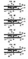
- FIGS. 4 a , 4 b , 4 c , and 4 dare cross-section views of belleville washers having radially varying thicknesses of the type which are utilized in conjunction with an embodiment of the present invention, the belleville washer of FIG. 4 a having a continuous washer shape with a thinner inner portion than outer, the belleville washer of FIG. 4 b having a slotted washer shape with a thinner inner portion than outer, the belleville washer of FIG. 4 c having a continuous washer shape with a thicker inner portion than outer, and the belleville washer of FIG. 4 a having a slotted washer shape with a thicker inner portion than outer.
- FIGS. 5 a , 5 b , and 5 care top views of the opposing plates, and more particularly, FIG. 5 a is a top view of the plate having a post element which seats within the central opening of the belleville washer, FIG. 5 b is a top view of the plate having the circumferential skirt an retaining ring, in which a belleville washer of the type of either FIGS. 4 a or 4 c disposed within the skirt, and FIG. 5 c is a top view of the plate having the circumferential skirt an retaining ring, in which a belleville washer of the type of either FIGS. 4 b or 4 d disposed within the skirt.
- FIGS. 6 a , 6 b , 6 c , and 6 dare side cross-section views of various embodiment of the present invention which utilizes the corresponding belleville washers illustrated in FIGS. 4 a - 4 d mounted between the plates illustrated in FIGS. 3 a and 3 b.
- the platesinclude substantially flat surface portions 102 , 202 which seat against the opposing bone surfaces.
- the platesare to mate with the bone surfaces in such a way as to not rotate relative thereto. It is, therefore, preferred that the plates should include a porous coating 104 , 204 into which the bone of the vertebral body can grow. (Note that this limited fusion of the bone to the base plate does not extend across the intervertebral space.)
- plate 100further includes a circumferential skirt 106 which serves as a retaining wall, into which the large end of a belleville washer (see FIGS. 4 a - 4 d ) may be seated.
- the diameter of the retaining wall 106is preferably slightly wider than the diameter of the undeflected belleville washer such that the loading thereof can result in an unrestrained radial deflection of the washer.
- the inner surface of the retaining wall 106includes an annular recess into which a retaining ring may be provided for holding the belleville washer in place (see the assembled FIGS. 5 a - 5 d ).
- plate 200further includes a central post 206 which rises out of the interior face 208 at a nearly perpendicular angle.
- the top of this short post member 206includes a ball-shaped head 210 .
- the head 210includes a series of slots 212 which render it compressible and expandable in correspondence with a radial pressure (or a radial component of a pressure applied thereto).
- the ball-shaped head 210Prior to the insertion of the set screw 216 , the ball-shaped head 210 can deflect radially inward (so that the ball-shaped head contracts) permitting the belleville washer to be flexibly mounted thereon.
- the insertion of the set screw 216eliminates (or greatly reduces) capacity for this deflection.
- these belleville washers 130 a-dcomprise a domed circular shape (a section of a sphere or three dimensional paraboloid would be an appropriately corresponding shape), having an inner opening, or central opening 132 a-d and an outer edge 134 a-d .
- a compressive loadis applied to a belleville washer, the forces are directed into a hoop stress which tends to radially expand the washer. This hoop stress is counterbalanced by the material strength of the washer, and the strain of the material causes a deflection in the height of the washer.
- a belleville washerresponds to a compressive load by deflecting compressively, but provides a restoring force which is proportional to the elastic modulus of the material in a hoop stressed condition.
- the thickness (the distance from the concave surface to the convex surface) of the material which comprises the washervaries from the central opening 132 a-d region to the outer circumference 134 a-d of the element.
- the belleville washer 130 ahas a greater thickness at the outer edge 134 a than it is at the inner opening 132 a .
- the restoring force of a belleville washeris proportional to the elastic properties of the material as well as the quantity of material being loaded, the reduction of the material at the edge of the inner opening 132 permits a load/deflection profile in which the load which deflects the inner portion of the washer is less than the outer portion. This permits the washer to compress to initially compress easily under a light loading, but to rapidly (faster than a straight linear loading profile) become stiff and resist deflection. This loading profile is more anatomically relevant with respect to mimicking the performance of the cartilage present in a healthy intervertebral space.
- the belleville washer 130 balso has a greater thickness at the outer edge 134 b than it is at the inner opening 132 b .
- the washerfurther includes a series of spiral slots 138 b extending from the outer edge 134 b toward the inner opening 132 b .
- the slots 138 bextend from the outer diameter of the belleville washer, inward along arcs generally directed toward the central opening 132 b of the element.
- the slots 138 bdo not extend fully to the center of the device.
- the slotsmay extend anywhere from a quarter to three quarters of the overall radius of the washer, depending upon the requirements of the patient, and the anatomical requirements of the device.
- the varying thickness combined with the slots 138 bpermits a load/deflection profile in which the load which deflects the inner portion of the washer is less than the outer portion. This permits the washer to compress to initially compress easily under a light loading, but to rapidly (faster than a straight linear loading profile) become stiff and resist deflection.
- This loading profileis more anatomically relevant with respect to mimicking the performance of the cartilage present in a healthy intervertebral space.
- the belleville washer 130 chas a smaller thickness at the outer edge 134 c than it is at the inner opening 132 c .
- the restoring force of a belleville washeris proportional to the elastic properties of the material as well as the quantity of material being loaded, the reduction of the material at the outer edge 134 c permits a load profile in which the load which deflects the outer portion of the washer is less than the inner portion. This permits the washer to compress to initially compress easily under a light loading(as a result of outer edge deflection), but to rapidly (faster than a straight linear loading profile) become stiff and resist deflection.
- This loading profileis more anatomically relevant with respect to mimicking the performance of the cartilage present in a healthy intervertebral space.
- the belleville washer 130 dhas a smaller thickness at the outer edge 134 d than it is at the inner opening 132 d .
- the washerfurther includes a series of spiral slots 138 d extending from the outer edge 134 d toward the inner opening 132 d .
- the slots 138 dextend from the outer diameter of the belleville washer, inward along arcs generally directed toward the central opening 132 d of the element.
- the slots 138 ddo not extend fully to the center of the device.
- the slotsmay extend anywhere from a quarter to three quarters of the overall radius of the washer, depending upon the requirements of the patient, and the anatomical requirements of the device.
- the varying thickness combined with the slots 138 dpermits a load/deflection profile in which the load which deflects the inner portion of the washer is less than the outer portion. This permits the washer to compress to initially compress easily under a light loading, but to rapidly (faster than a straight linear loading profile) become stiff and resist deflection.
- This loading profileis more anatomically relevant with respect to mimicking the performance of the cartilage present in a healthy intervertebral space.
- each of the belleville washer embodiments described hereinabovefurther includes a curvate volume 136 a-d (best shown in FIGS. 4 a - 4 d ) for receiving therein the ball-shaped head 210 of the post 206 of the lower plate 200 described above.
- FIGS. 6 a - 6 dside cross-sectional views of the fully assembled embodiments of the intervertebral spacers which comprises the present invention are provided.
- Each structureincludes the belleville washer (selected from the corresponding ones illustrated in FIGS. 4 a - 4 d ).
- Eachfurther includes the following common features: two opposing plates 100 , 200 having their flat surfaces 102 , 202 , respectively, directed away from one another (to be seated against the adjacent bone); a retaining ring 110 is seated in the annular groove of the retaining wall 106 ; and a ball-shaped-headed central post 206 extending into the central opening 132 a-d of the corresponding belleville washer 130 a-d rotatably secured in place by set screw 216 .
- the deflectability of the ball-shaped head of the post 206prior to the insertion of the set screw 216 , permits the head to be inserted into the interior volume at the center of the belleville washer 130 a-d .
Landscapes
- Health & Medical Sciences (AREA)
- Engineering & Computer Science (AREA)
- Biomedical Technology (AREA)
- Neurology (AREA)
- Orthopedic Medicine & Surgery (AREA)
- Cardiology (AREA)
- Oral & Maxillofacial Surgery (AREA)
- Transplantation (AREA)
- Heart & Thoracic Surgery (AREA)
- Vascular Medicine (AREA)
- Life Sciences & Earth Sciences (AREA)
- Animal Behavior & Ethology (AREA)
- General Health & Medical Sciences (AREA)
- Public Health (AREA)
- Veterinary Medicine (AREA)
- Prostheses (AREA)
Abstract
Description
Claims (7)
Priority Applications (16)
| Application Number | Priority Date | Filing Date | Title |
|---|---|---|---|
| US09/968,045US6740117B2 (en) | 2001-02-15 | 2001-10-01 | Intervertebral spacer device having a radially thinning slotted belleville spring |
| DE60235824TDE60235824D1 (en) | 2001-10-01 | 2002-06-19 | ARTIFICIAL BELT WITH SLOTTED BELLEVILLEMENT |
| EP02746610AEP1437988B1 (en) | 2001-10-01 | 2002-06-19 | Artificial intervertebral disc having a slotted belleville washer force restoring element |
| PCT/US2002/019660WO2003028595A1 (en) | 2001-10-01 | 2002-06-19 | Artificial intervertebral disc having a slotted belleville washer force restoring element |
| IL16113602AIL161136A0 (en) | 2001-10-01 | 2002-06-19 | Artificial intervertebral disc |
| AU2002316316AAU2002316316B2 (en) | 2001-10-01 | 2002-06-19 | Artificial intervertebral disc having a slotted belleville washer force restoring element |
| EP10178946AEP2319465B1 (en) | 2001-10-01 | 2002-06-19 | Artificial intervertebral disc having a slotted belleville washer force restoring element |
| JP2003531935AJP4202918B2 (en) | 2001-10-01 | 2002-06-19 | Artificial intervertebral disc with slotted Belleville washers as restoring force supply member |
| CA002461791ACA2461791C (en) | 2001-10-01 | 2002-06-19 | Artificial intervertebral disc having a slotted belleville washer force restoring element |
| AT02746610TATE462381T1 (en) | 2001-10-01 | 2002-06-19 | ARTIFICIAL DISC WITH SLOTTED BELLEVILLE WASHER AS A FORCE-RESTORING ELEMENT |
| EP10152823AEP2177180B1 (en) | 2001-10-01 | 2002-06-19 | Artificial intervertebral disc having a slotted belleville washer force restoring element |
| US10/177,013US6918934B2 (en) | 2001-10-01 | 2002-06-21 | Artificial intervertebral disc having a slotted belleville washer force restoring element |
| US10/784,645US8858564B2 (en) | 2001-02-15 | 2004-02-23 | Wedge plate inserter/impactor and related methods for use in implanting an artificial intervertebral disc |
| IL161136AIL161136A (en) | 2001-10-01 | 2004-03-29 | Artificial intervertebral disc |
| US10/833,739US20040204764A1 (en) | 2001-10-01 | 2004-04-28 | Intervertebral spacer device having a radially thinning slotted belleville spring |
| US11/157,551US8048159B2 (en) | 2001-10-01 | 2005-06-21 | Artificial intervertebral disc having a slotted belleville washer force restoring element |
Applications Claiming Priority (2)
| Application Number | Priority Date | Filing Date | Title |
|---|---|---|---|
| US78993601A | 2001-02-15 | 2001-02-15 | |
| US09/968,045US6740117B2 (en) | 2001-02-15 | 2001-10-01 | Intervertebral spacer device having a radially thinning slotted belleville spring |
Related Parent Applications (1)
| Application Number | Title | Priority Date | Filing Date |
|---|---|---|---|
| US78993601AContinuation-In-Part | 2001-02-15 | 2001-02-15 |
Related Child Applications (3)
| Application Number | Title | Priority Date | Filing Date |
|---|---|---|---|
| US09/970,479Continuation-In-PartUS6669730B2 (en) | 2001-02-15 | 2001-10-04 | Intervertebral spacer device utilizing a spirally slotted belleville washer having radially extending grooves |
| US10/177,013Continuation-In-PartUS6918934B2 (en) | 2001-10-01 | 2002-06-21 | Artificial intervertebral disc having a slotted belleville washer force restoring element |
| US10/833,739ContinuationUS20040204764A1 (en) | 2001-10-01 | 2004-04-28 | Intervertebral spacer device having a radially thinning slotted belleville spring |
Publications (2)
| Publication Number | Publication Date |
|---|---|
| US20020111681A1 US20020111681A1 (en) | 2002-08-15 |
| US6740117B2true US6740117B2 (en) | 2004-05-25 |
Family
ID=25513641
Family Applications (4)
| Application Number | Title | Priority Date | Filing Date |
|---|---|---|---|
| US09/968,045Expired - Fee RelatedUS6740117B2 (en) | 2001-02-15 | 2001-10-01 | Intervertebral spacer device having a radially thinning slotted belleville spring |
| US10/177,013Expired - Fee RelatedUS6918934B2 (en) | 2001-10-01 | 2002-06-21 | Artificial intervertebral disc having a slotted belleville washer force restoring element |
| US10/833,739AbandonedUS20040204764A1 (en) | 2001-10-01 | 2004-04-28 | Intervertebral spacer device having a radially thinning slotted belleville spring |
| US11/157,551Expired - Fee RelatedUS8048159B2 (en) | 2001-10-01 | 2005-06-21 | Artificial intervertebral disc having a slotted belleville washer force restoring element |
Family Applications After (3)
| Application Number | Title | Priority Date | Filing Date |
|---|---|---|---|
| US10/177,013Expired - Fee RelatedUS6918934B2 (en) | 2001-10-01 | 2002-06-21 | Artificial intervertebral disc having a slotted belleville washer force restoring element |
| US10/833,739AbandonedUS20040204764A1 (en) | 2001-10-01 | 2004-04-28 | Intervertebral spacer device having a radially thinning slotted belleville spring |
| US11/157,551Expired - Fee RelatedUS8048159B2 (en) | 2001-10-01 | 2005-06-21 | Artificial intervertebral disc having a slotted belleville washer force restoring element |
Country Status (9)
| Country | Link |
|---|---|
| US (4) | US6740117B2 (en) |
| EP (3) | EP1437988B1 (en) |
| JP (1) | JP4202918B2 (en) |
| AT (1) | ATE462381T1 (en) |
| AU (1) | AU2002316316B2 (en) |
| CA (1) | CA2461791C (en) |
| DE (1) | DE60235824D1 (en) |
| IL (2) | IL161136A0 (en) |
| WO (1) | WO2003028595A1 (en) |
Cited By (85)
| Publication number | Priority date | Publication date | Assignee | Title |
|---|---|---|---|---|
| US20030174929A1 (en)* | 2002-03-15 | 2003-09-18 | Rodgers Murray Steven | Self-shadowing MEM structures |
| US20040002761A1 (en)* | 2002-06-27 | 2004-01-01 | Christopher Rogers | Intervertebral disc having translation |
| US20040092943A1 (en)* | 2002-01-14 | 2004-05-13 | Buttermann Glenn Robin | Apparatus and method for performing spinal surgery |
| US20040243240A1 (en)* | 2001-05-04 | 2004-12-02 | Jacques Beaurain | Intervertebral disc prosthesis and fitting tools |
| US20050033438A1 (en)* | 2003-07-08 | 2005-02-10 | Robert Schultz | Intervertebral implant |
| US20050043803A1 (en)* | 2003-08-22 | 2005-02-24 | Robert Schultz | Intervertebral implant |
| US20050113924A1 (en)* | 2003-08-07 | 2005-05-26 | Dynamic Spine, Inc. | Apparatus and method for performing spinal surgery |
| US20050234554A1 (en)* | 2001-10-01 | 2005-10-20 | Spinecore, Inc. | Artificial intervertebral disc having a slotted belleville washer force restoring element |
| US20050261772A1 (en)* | 2004-05-18 | 2005-11-24 | Zimmer Gmbh | Intervertebral disk implant |
| US20060009541A1 (en)* | 2004-07-09 | 2006-01-12 | Yih-Fang Chen | Saturant for friction material containing friction modifying layer |
| US20060217809A1 (en)* | 2005-03-24 | 2006-09-28 | Accin Corporation | Intervertebral disc replacement device |
| US20060265072A1 (en)* | 2003-05-06 | 2006-11-23 | Marc Richelsoph | Artificial intervertebral disc |
| US20060265073A1 (en)* | 2001-10-01 | 2006-11-23 | Spinecore, Inc. | Intervertebral spacer device |
| US20060293752A1 (en)* | 2005-06-27 | 2006-12-28 | Missoum Moumene | Intervertebral disc prosthesis and associated methods |
| US20070016217A1 (en)* | 2005-06-29 | 2007-01-18 | Ldr Medical | Instrumentation and methods for inserting an intervertebral disc prosthesis |
| US7291170B2 (en) | 2000-05-18 | 2007-11-06 | Ldr Medical | Intersomatic cage with unified grafts |
| US20080262621A1 (en)* | 2007-04-17 | 2008-10-23 | K2M, Inc. | I-beam spacer |
| US7494508B2 (en) | 2004-04-28 | 2009-02-24 | Ldr Medical | Intervertebral disc prosthesis |
| US7549995B2 (en) | 2003-07-08 | 2009-06-23 | Aesculap Ag | Surgical instrument for handling an implant |
| US20090222092A1 (en)* | 2006-02-15 | 2009-09-03 | Reginald James Davis | Transforaminal intersomatic cage for an intervertebral fusion graft and an instrument for implanting the cage |
| US7585325B2 (en) | 2004-06-16 | 2009-09-08 | Aesculap Ag | Intervertebral implant |
| US7594931B2 (en) | 2001-07-13 | 2009-09-29 | Ldr Medical | Vertebral cage device with modular fixation |
| US7682396B2 (en) | 2002-11-05 | 2010-03-23 | Ldr Medical | Intervertebral disc prosthesis |
| US7695516B2 (en) | 2004-12-22 | 2010-04-13 | Ldr Medical | Intervertebral disc prosthesis |
| US20100161064A1 (en)* | 2006-11-07 | 2010-06-24 | Kellar Franz W | Prosthetic joint |
| US20100168863A1 (en)* | 2003-07-15 | 2010-07-01 | Spinal Generations, Llc | Spinal disc prosthesis system |
| US7799081B2 (en) | 2004-09-14 | 2010-09-21 | Aeolin, Llc | System and method for spinal fusion |
| US20100262250A1 (en)* | 2006-11-07 | 2010-10-14 | Kellar Franz W | Prosthetic ball-and-socket joint |
| US7815648B2 (en) | 2004-06-02 | 2010-10-19 | Facet Solutions, Inc | Surgical measurement systems and methods |
| US7832409B2 (en) | 2003-05-06 | 2010-11-16 | Aesculap Implant Systems, Llc | Method of inserting an artificial intervertebral disc |
| US7842088B2 (en) | 2005-09-23 | 2010-11-30 | Ldr Medical | Intervertebral disc prosthesis |
| US7914560B2 (en) | 2004-02-17 | 2011-03-29 | Gmedelaware 2 Llc | Spinal facet implant with spherical implant apposition surface and bone bed and methods of use |
| US8016886B2 (en) | 2006-07-18 | 2011-09-13 | Altus Partners, Llc | Intervertebral disc replacement device |
| US8029574B2 (en) | 2006-11-07 | 2011-10-04 | Biomedflex Llc | Prosthetic knee joint |
| US8070823B2 (en) | 2006-11-07 | 2011-12-06 | Biomedflex Llc | Prosthetic ball-and-socket joint |
| US8206418B2 (en) | 2007-01-10 | 2012-06-26 | Gmedelaware 2 Llc | System and method for facet joint replacement with detachable coupler |
| US8308812B2 (en) | 2006-11-07 | 2012-11-13 | Biomedflex, Llc | Prosthetic joint assembly and joint member therefor |
| US8343219B2 (en) | 2007-06-08 | 2013-01-01 | Ldr Medical | Intersomatic cage, intervertebral prosthesis, anchoring device and implantation instruments |
| US8465546B2 (en) | 2007-02-16 | 2013-06-18 | Ldr Medical | Intervertebral disc prosthesis insertion assemblies |
| US8512413B2 (en) | 2006-11-07 | 2013-08-20 | Biomedflex, Llc | Prosthetic knee joint |
| US8777994B2 (en) | 2004-06-02 | 2014-07-15 | Gmedelaware 2 Llc | System and method for multiple level facet joint arthroplasty and fusion |
| US8858635B2 (en) | 2004-02-04 | 2014-10-14 | Ldr Medical | Intervertebral disc prosthesis |
| US9005306B2 (en) | 2006-11-07 | 2015-04-14 | Biomedflex, Llc | Medical Implants With Compliant Wear-Resistant Surfaces |
| US9005307B2 (en) | 2006-11-07 | 2015-04-14 | Biomedflex, Llc | Prosthetic ball-and-socket joint |
| US9039774B2 (en) | 2012-02-24 | 2015-05-26 | Ldr Medical | Anchoring device and system for an intervertebral implant, intervertebral implant and implantation instrument |
| US9044337B2 (en) | 2009-12-31 | 2015-06-02 | Ldr Medical | Anchoring device and system for an intervertebral implant, intervertebral implant and implantation instrument |
| US9265618B2 (en) | 2005-11-30 | 2016-02-23 | Ldr Medical | Intervertebral disc prosthesis and instrumentation for insertion of the prosthesis between the vertebrae |
| US9320615B2 (en) | 2010-06-29 | 2016-04-26 | DePuy Synthes Products, Inc. | Distractible intervertebral implant |
| US9358122B2 (en) | 2011-01-07 | 2016-06-07 | K2M, Inc. | Interbody spacer |
| US9463091B2 (en) | 2009-09-17 | 2016-10-11 | Ldr Medical | Intervertebral implant having extendable bone fixation members |
| US9566157B2 (en) | 2006-11-07 | 2017-02-14 | Biomedflex, Llc | Three-member prosthetic joint |
| US9700429B2 (en) | 2001-07-16 | 2017-07-11 | Spinecore, Inc. | Intervertebral spacer device having recessed notch pairs for manipulation using a surgical tool |
| US9717601B2 (en) | 2013-02-28 | 2017-08-01 | DePuy Synthes Products, Inc. | Expandable intervertebral implant, system, kit and method |
| US9724207B2 (en) | 2003-02-14 | 2017-08-08 | DePuy Synthes Products, Inc. | In-situ formed intervertebral fusion device and method |
| US9750552B2 (en) | 2009-07-06 | 2017-09-05 | DePuy Synthes Products, Inc. | Expandable fixation assemblies |
| US9833334B2 (en) | 2010-06-24 | 2017-12-05 | DePuy Synthes Products, Inc. | Enhanced cage insertion assembly |
| US9839530B2 (en) | 2007-06-26 | 2017-12-12 | DePuy Synthes Products, Inc. | Highly lordosed fusion cage |
| US9913727B2 (en) | 2015-07-02 | 2018-03-13 | Medos International Sarl | Expandable implant |
| US9931223B2 (en) | 2008-04-05 | 2018-04-03 | DePuy Synthes Products, Inc. | Expandable intervertebral implant |
| US9949769B2 (en) | 2004-03-06 | 2018-04-24 | DePuy Synthes Products, Inc. | Dynamized interspinal implant |
| US10058433B2 (en) | 2012-07-26 | 2018-08-28 | DePuy Synthes Products, Inc. | Expandable implant |
| US10390963B2 (en) | 2006-12-07 | 2019-08-27 | DePuy Synthes Products, Inc. | Intervertebral implant |
| US10398563B2 (en) | 2017-05-08 | 2019-09-03 | Medos International Sarl | Expandable cage |
| US10433974B2 (en) | 2003-06-30 | 2019-10-08 | DePuy Synthes Products, Inc. | Intervertebral implant with conformable endplate |
| US10433977B2 (en) | 2008-01-17 | 2019-10-08 | DePuy Synthes Products, Inc. | Expandable intervertebral implant and associated method of manufacturing the same |
| US10500062B2 (en) | 2009-12-10 | 2019-12-10 | DePuy Synthes Products, Inc. | Bellows-like expandable interbody fusion cage |
| US10537436B2 (en) | 2016-11-01 | 2020-01-21 | DePuy Synthes Products, Inc. | Curved expandable cage |
| US10603185B2 (en) | 2004-02-04 | 2020-03-31 | Ldr Medical | Intervertebral disc prosthesis |
| US10888433B2 (en) | 2016-12-14 | 2021-01-12 | DePuy Synthes Products, Inc. | Intervertebral implant inserter and related methods |
| US10940016B2 (en) | 2017-07-05 | 2021-03-09 | Medos International Sarl | Expandable intervertebral fusion cage |
| US11096802B2 (en) | 2018-03-03 | 2021-08-24 | K2M, Inc. | Intervertebral trial with marker |
| US11344424B2 (en) | 2017-06-14 | 2022-05-31 | Medos International Sarl | Expandable intervertebral implant and related methods |
| US11426290B2 (en) | 2015-03-06 | 2022-08-30 | DePuy Synthes Products, Inc. | Expandable intervertebral implant, system, kit and method |
| US11426286B2 (en) | 2020-03-06 | 2022-08-30 | Eit Emerging Implant Technologies Gmbh | Expandable intervertebral implant |
| US11446156B2 (en) | 2018-10-25 | 2022-09-20 | Medos International Sarl | Expandable intervertebral implant, inserter instrument, and related methods |
| US11452607B2 (en) | 2010-10-11 | 2022-09-27 | DePuy Synthes Products, Inc. | Expandable interspinous process spacer implant |
| US11497619B2 (en) | 2013-03-07 | 2022-11-15 | DePuy Synthes Products, Inc. | Intervertebral implant |
| US11510788B2 (en) | 2016-06-28 | 2022-11-29 | Eit Emerging Implant Technologies Gmbh | Expandable, angularly adjustable intervertebral cages |
| US11596522B2 (en) | 2016-06-28 | 2023-03-07 | Eit Emerging Implant Technologies Gmbh | Expandable and angularly adjustable intervertebral cages with articulating joint |
| US11612491B2 (en) | 2009-03-30 | 2023-03-28 | DePuy Synthes Products, Inc. | Zero profile spinal fusion cage |
| US11752009B2 (en) | 2021-04-06 | 2023-09-12 | Medos International Sarl | Expandable intervertebral fusion cage |
| US11850160B2 (en) | 2021-03-26 | 2023-12-26 | Medos International Sarl | Expandable lordotic intervertebral fusion cage |
| US11911287B2 (en) | 2010-06-24 | 2024-02-27 | DePuy Synthes Products, Inc. | Lateral spondylolisthesis reduction cage |
| US12090064B2 (en) | 2022-03-01 | 2024-09-17 | Medos International Sarl | Stabilization members for expandable intervertebral implants, and related systems and methods |
| US12440346B2 (en) | 2023-03-31 | 2025-10-14 | DePuy Synthes Products, Inc. | Expandable intervertebral implant |
Families Citing this family (88)
| Publication number | Priority date | Publication date | Assignee | Title |
|---|---|---|---|---|
| US6989032B2 (en)* | 2001-07-16 | 2006-01-24 | Spinecore, Inc. | Artificial intervertebral disc |
| US6669730B2 (en) | 2001-02-15 | 2003-12-30 | Spinecore, Inc. | Intervertebral spacer device utilizing a spirally slotted belleville washer having radially extending grooves |
| US7604664B2 (en) | 2001-07-16 | 2009-10-20 | Spinecore, Inc. | Spinal baseplates with ball joint coupling and a retaining member |
| US7235081B2 (en) | 2001-07-16 | 2007-06-26 | Spinecore, Inc. | Wedge plate inserter/impactor and related methods for use in implanting an artificial intervertebral disc |
| US6673113B2 (en)* | 2001-10-18 | 2004-01-06 | Spinecore, Inc. | Intervertebral spacer device having arch shaped spring elements |
| US7115132B2 (en) | 2001-07-16 | 2006-10-03 | Spinecore, Inc. | Static trials and related instruments and methods for use in implanting an artificial intervertebral disc |
| US6607559B2 (en)* | 2001-07-16 | 2003-08-19 | Spine Care, Inc. | Trial intervertebral distraction spacers |
| US7223291B2 (en)* | 2001-07-16 | 2007-05-29 | Spinecore, Inc. | Intervertebral spacer device having engagement hole pairs for manipulation using a surgical tool |
| US20030069642A1 (en)* | 2001-10-04 | 2003-04-10 | Ralph James D. | Artificial intervertebral disc having a flexible wire mesh vertebral body contact element |
| US7563285B2 (en)* | 2001-07-16 | 2009-07-21 | Spinecore, Inc. | Artificial intervertebral disc utilizing a ball joint coupling |
| US7169182B2 (en) | 2001-07-16 | 2007-01-30 | Spinecore, Inc. | Implanting an artificial intervertebral disc |
| US8858564B2 (en)* | 2001-02-15 | 2014-10-14 | Spinecore, Inc. | Wedge plate inserter/impactor and related methods for use in implanting an artificial intervertebral disc |
| US7575576B2 (en)* | 2001-07-16 | 2009-08-18 | Spinecore, Inc. | Wedge ramp distractor and related methods for use in implanting artificial intervertebral discs |
| US6863689B2 (en)* | 2001-07-16 | 2005-03-08 | Spinecore, Inc. | Intervertebral spacer having a flexible wire mesh vertebral body contact element |
| US7635368B2 (en)* | 2001-07-16 | 2009-12-22 | Spinecore, Inc. | Intervertebral spacer device having simultaneously engageable angled perimeters for manipulation using a surgical tool |
| US7160327B2 (en) | 2001-07-16 | 2007-01-09 | Spinecore, Inc. | Axially compressible artificial intervertebral disc having limited rotation using a captured ball and socket joint with a solid ball and compression locking post |
| US6471725B1 (en)* | 2001-07-16 | 2002-10-29 | Third Millenium Engineering, Llc | Porous intervertebral distraction spacers |
| US7722675B2 (en)* | 2001-07-16 | 2010-05-25 | Spinecore, Inc. | Instruments for reorienting vertebral bones for the treatment of scoliosis |
| US8366775B2 (en)* | 2001-07-16 | 2013-02-05 | Spinecore, Inc. | Intervertebral spacer device having an angled perimeter for manipulation using a surgical tool |
| US7118599B2 (en) | 2001-07-16 | 2006-10-10 | Spinecore, Inc. | Artificial intervertebral disc |
| US7771477B2 (en) | 2001-10-01 | 2010-08-10 | Spinecore, Inc. | Intervertebral spacer device utilizing a belleville washer having radially spaced concentric grooves |
| US20090177283A9 (en)* | 2001-10-01 | 2009-07-09 | Ralph James D | Intervertebral spacer device utilizing a spirally slotted belleville washer and a rotational mounting |
| US7208014B2 (en)* | 2001-10-01 | 2007-04-24 | Spinecore, Inc. | Intervertebral spacer device utilizing a belleville washer having radially extending grooves |
| US7713302B2 (en) | 2001-10-01 | 2010-05-11 | Spinecore, Inc. | Intervertebral spacer device utilizing a spirally slotted belleville washer having radially spaced concentric grooves |
| US8038713B2 (en) | 2002-04-23 | 2011-10-18 | Spinecore, Inc. | Two-component artificial disc replacements |
| US20080027548A9 (en) | 2002-04-12 | 2008-01-31 | Ferree Bret A | Spacerless artificial disc replacements |
| EP1542626B1 (en) | 2002-08-15 | 2012-09-26 | Synthes GmbH | Controlled artificial intervertebral disc implant |
| CA2495404C (en) | 2002-08-15 | 2011-05-03 | Justin K. Coppes | Intervertebral disc implant |
| JP4654125B2 (en)* | 2002-10-29 | 2011-03-16 | スパインコア,インコーポレイテッド | Instruments, methods, and functions for use in implanting an artificial disc |
| GB0228575D0 (en)* | 2002-12-07 | 2003-01-15 | Depuy Int Ltd | A bone cement plug |
| US6908484B2 (en) | 2003-03-06 | 2005-06-21 | Spinecore, Inc. | Cervical disc replacement |
| US20050143824A1 (en)* | 2003-05-06 | 2005-06-30 | Marc Richelsoph | Artificial intervertebral disc |
| DE10324108B3 (en)* | 2003-05-21 | 2005-01-27 | Aesculap Ag & Co. Kg | Backbone implant is inserted with contracted contact disc which is expanded to optimum area following insertion |
| CN100566677C (en)* | 2003-07-22 | 2009-12-09 | 斯恩蒂斯有限公司 | The intraarticular prosthese |
| US7621956B2 (en)* | 2003-07-31 | 2009-11-24 | Globus Medical, Inc. | Prosthetic spinal disc replacement |
| US7811329B2 (en) | 2003-07-31 | 2010-10-12 | Globus Medical | Transforaminal prosthetic spinal disc replacement and methods thereof |
| US7713304B2 (en) | 2003-07-31 | 2010-05-11 | Globus Medical, Inc. | Transforaminal prosthetic spinal disc replacement |
| DE20315613U1 (en)* | 2003-10-08 | 2003-12-11 | Aesculap Ag & Co. Kg | Intervertebral implant |
| DE20315611U1 (en)* | 2003-10-08 | 2003-12-11 | Aesculap Ag & Co. Kg | Intervertebral implant |
| US8123757B2 (en)* | 2003-12-31 | 2012-02-28 | Depuy Spine, Inc. | Inserter instrument and implant clip |
| US7393361B2 (en)* | 2004-02-20 | 2008-07-01 | Spinecore, Inc. | Artificial intervertebral disc having a bored semispherical bearing with a compression locking post and retaining caps |
| US7468076B2 (en) | 2004-02-20 | 2008-12-23 | Spinecore, Inc. | Artificial intervertebral disc having a universal joint |
| WO2005094733A1 (en)* | 2004-04-02 | 2005-10-13 | Synthes Gmbh | Intervertebral disc prosthesis or artificial vertebral body |
| FR2876900B1 (en) | 2004-10-22 | 2007-01-05 | Sdgi Holdings Inc | INTERVERTEBRAL IMPLANT AND DEVICE FOR STABILIZING THE RACHIS COMPRISING THE SAME |
| WO2006058221A2 (en) | 2004-11-24 | 2006-06-01 | Abdou Samy M | Devices and methods for inter-vertebral orthopedic device placement |
| US7867279B2 (en)* | 2006-01-23 | 2011-01-11 | Depuy Spine, Inc. | Intervertebral disc prosthesis |
| WO2007095333A2 (en)* | 2006-02-15 | 2007-08-23 | Abdou M S | Devices and methods for inter-vertebral orthopedic device placement |
| US20070203580A1 (en)* | 2006-02-24 | 2007-08-30 | Paonan Biotech Co., Ltd. | Intervertebral filling |
| US8303660B1 (en) | 2006-04-22 | 2012-11-06 | Samy Abdou | Inter-vertebral disc prosthesis with variable rotational stop and methods of use |
| WO2007140382A2 (en)* | 2006-05-26 | 2007-12-06 | Abdou M S | Inter-vertebral disc motion devices and methods of use |
| US20080039843A1 (en)* | 2006-08-11 | 2008-02-14 | Abdou M S | Spinal motion preservation devices and methods of use |
| US8066750B2 (en) | 2006-10-06 | 2011-11-29 | Warsaw Orthopedic, Inc | Port structures for non-rigid bone plates |
| US9107705B2 (en)* | 2006-12-11 | 2015-08-18 | M. Samy Abdou | Dynamic spinal stabilization systems and methods of use |
| US8715352B2 (en)* | 2006-12-14 | 2014-05-06 | Depuy Spine, Inc. | Buckling disc replacement |
| US8579910B2 (en) | 2007-05-18 | 2013-11-12 | DePuy Synthes Products, LLC | Insertion blade assembly and method of use |
| US8298287B2 (en)* | 2007-06-26 | 2012-10-30 | Depuy Spine, Inc. | Intervertebral motion disc with helical shock absorber |
| US7841475B2 (en)* | 2007-08-15 | 2010-11-30 | Kalustyan Corporation | Continuously operating machine having magnets |
| US7799056B2 (en) | 2007-12-31 | 2010-09-21 | Warsaw Orthopedic, Inc. | Bone fusion device and methods |
| US7985231B2 (en) | 2007-12-31 | 2011-07-26 | Kyphon Sarl | Bone fusion device and methods |
| US8795365B2 (en)* | 2008-03-24 | 2014-08-05 | Warsaw Orthopedic, Inc | Expandable devices for emplacement in body parts and methods associated therewith |
| KR20110049771A (en)* | 2008-07-14 | 2011-05-12 | 신세스 게엠바하 | Flexible buffering intervertebral spacer device |
| US20110137346A1 (en)* | 2008-08-14 | 2011-06-09 | Synthes Usa, Llc | Posterior dynamic stabilization system |
| US7927375B2 (en) | 2008-09-12 | 2011-04-19 | Doty Keith L | Dynamic six-degrees-of-freedom intervertebral spinal disc prosthesis |
| US20100161058A1 (en)* | 2008-12-24 | 2010-06-24 | Custom Spine, Inc. | Multiple-State Geometry Artificial Disc With Compliant Insert and Method |
| US8906033B2 (en) | 2009-03-30 | 2014-12-09 | DePuy Synthes Products, LLC | Cervical motion disc inserter |
| US8226724B2 (en)* | 2009-06-18 | 2012-07-24 | Doty Keith L | Intervertebral spinal disc prosthesis |
| US9028553B2 (en) | 2009-11-05 | 2015-05-12 | DePuy Synthes Products, Inc. | Self-pivoting spinal implant and associated instrumentation |
| US20110112644A1 (en)* | 2009-11-12 | 2011-05-12 | Zilberstein Boris | Disc prosthetic implant device |
| US8277509B2 (en) | 2009-12-07 | 2012-10-02 | Globus Medical, Inc. | Transforaminal prosthetic spinal disc apparatus |
| US8764806B2 (en) | 2009-12-07 | 2014-07-01 | Samy Abdou | Devices and methods for minimally invasive spinal stabilization and instrumentation |
| US8142477B2 (en)* | 2010-01-21 | 2012-03-27 | Warsaw Orthopedic, Inc. | Retaining system |
| US8496713B2 (en)* | 2010-12-10 | 2013-07-30 | Globus Medical, Inc. | Spine stabilization device and methods |
| US8277505B1 (en) | 2011-06-10 | 2012-10-02 | Doty Keith L | Devices for providing up to six-degrees of motion having kinematically-linked components and methods of use |
| US8845728B1 (en) | 2011-09-23 | 2014-09-30 | Samy Abdou | Spinal fixation devices and methods of use |
| US9017410B2 (en) | 2011-10-26 | 2015-04-28 | Globus Medical, Inc. | Artificial discs |
| US8287598B1 (en) | 2011-12-05 | 2012-10-16 | TrueMotion Spine, Inc. | True spinal motion preserving, shock absorbing, intervertebral spinal disc prosthesis |
| US20130226240A1 (en) | 2012-02-22 | 2013-08-29 | Samy Abdou | Spinous process fixation devices and methods of use |
| US9039745B2 (en) | 2012-04-26 | 2015-05-26 | Biomet Manufacturing, Llc | One-piece variable angle locking washer |
| US9198767B2 (en) | 2012-08-28 | 2015-12-01 | Samy Abdou | Devices and methods for spinal stabilization and instrumentation |
| US9320617B2 (en) | 2012-10-22 | 2016-04-26 | Cogent Spine, LLC | Devices and methods for spinal stabilization and instrumentation |
| US10022245B2 (en) | 2012-12-17 | 2018-07-17 | DePuy Synthes Products, Inc. | Polyaxial articulating instrument |
| US9198770B2 (en) | 2013-07-31 | 2015-12-01 | Globus Medical, Inc. | Artificial disc devices and related methods of use |
| US10857003B1 (en) | 2015-10-14 | 2020-12-08 | Samy Abdou | Devices and methods for vertebral stabilization |
| US10744000B1 (en) | 2016-10-25 | 2020-08-18 | Samy Abdou | Devices and methods for vertebral bone realignment |
| US10973648B1 (en) | 2016-10-25 | 2021-04-13 | Samy Abdou | Devices and methods for vertebral bone realignment |
| US10966843B2 (en) | 2017-07-18 | 2021-04-06 | DePuy Synthes Products, Inc. | Implant inserters and related methods |
| US11045331B2 (en) | 2017-08-14 | 2021-06-29 | DePuy Synthes Products, Inc. | Intervertebral implant inserters and related methods |
| US11179248B2 (en) | 2018-10-02 | 2021-11-23 | Samy Abdou | Devices and methods for spinal implantation |
Citations (26)
| Publication number | Priority date | Publication date | Assignee | Title |
|---|---|---|---|---|
| US1641059A (en)* | 1925-05-19 | 1927-08-30 | Tausch Ernst | Resilient-ring element |
| US4303001A (en) | 1977-08-18 | 1981-12-01 | Trungold Emanuel H | Bolt tension indicating means |
| US4932969A (en) | 1987-01-08 | 1990-06-12 | Sulzer Brothers Limited | Joint endoprosthesis |
| US4958970A (en)* | 1988-08-17 | 1990-09-25 | The United States Of America As Represented By The Secretary Of The Navy | Graduated-load spring washer system for screws and threaded fasteners |
| US5458642A (en) | 1994-01-18 | 1995-10-17 | Beer; John C. | Synthetic intervertebral disc |
| US5535861A (en)* | 1995-06-08 | 1996-07-16 | Lord Corporation | Dual-rate linear damper |
| US5556431A (en) | 1992-03-13 | 1996-09-17 | B+E,Uml U+Ee Ttner-Janz; Karin | Intervertebral disc endoprosthesis |
| US5562738A (en) | 1992-01-06 | 1996-10-08 | Danek Medical, Inc. | Intervertebral disk arthroplasty device |
| US5674296A (en) | 1994-11-14 | 1997-10-07 | Spinal Dynamics Corporation | Human spinal disc prosthesis |
| US5676701A (en) | 1993-01-14 | 1997-10-14 | Smith & Nephew, Inc. | Low wear artificial spinal disc |
| US5676702A (en) | 1994-12-16 | 1997-10-14 | Tornier S.A. | Elastic disc prosthesis |
| US5683465A (en) | 1996-03-18 | 1997-11-04 | Shinn; Gary Lee | Artificial intervertebral disk prosthesis |
| US5755796A (en) | 1996-06-06 | 1998-05-26 | Ibo; Ivo | Prosthesis of the cervical intervertebralis disk |
| US5827328A (en) | 1996-11-22 | 1998-10-27 | Buttermann; Glenn R. | Intervertebral prosthetic device |
| US5888226A (en) | 1997-11-12 | 1999-03-30 | Rogozinski; Chaim | Intervertebral prosthetic disc |
| US5895428A (en) | 1996-11-01 | 1999-04-20 | Berry; Don | Load bearing spinal joint implant |
| US5899941A (en) | 1997-12-09 | 1999-05-04 | Chubu Bearing Kabushiki Kaisha | Artificial intervertebral disk |
| US5989291A (en) | 1998-02-26 | 1999-11-23 | Third Millennium Engineering, Llc | Intervertebral spacer device |
| US6019792A (en) | 1998-04-23 | 2000-02-01 | Cauthen Research Group, Inc. | Articulating spinal implant |
| US6039763A (en) | 1998-10-27 | 2000-03-21 | Disc Replacement Technologies, Inc. | Articulating spinal disc prosthesis |
| US6063121A (en) | 1998-07-29 | 2000-05-16 | Xavier; Ravi | Vertebral body prosthesis |
| US6113637A (en) | 1998-10-22 | 2000-09-05 | Sofamor Danek Holdings, Inc. | Artificial intervertebral joint permitting translational and rotational motion |
| US6136031A (en) | 1998-06-17 | 2000-10-24 | Surgical Dynamics, Inc. | Artificial intervertebral disc |
| US6146421A (en) | 1997-08-04 | 2000-11-14 | Gordon, Maya, Roberts And Thomas, Number 1, Llc | Multiple axis intervertebral prosthesis |
| US6179874B1 (en) | 1998-04-23 | 2001-01-30 | Cauthen Research Group, Inc. | Articulating spinal implant |
| US6228118B1 (en) | 1997-08-04 | 2001-05-08 | Gordon, Maya, Roberts And Thomas, Number 1, Llc | Multiple axis intervertebral prosthesis |
Family Cites Families (22)
| Publication number | Priority date | Publication date | Assignee | Title |
|---|---|---|---|---|
| DE2263842A1 (en) | 1972-12-28 | 1974-07-04 | Hoffmann Daimler Siegfried Dr | DISC PROTHESIS |
| US4024829A (en)* | 1975-07-14 | 1977-05-24 | Chiang Shui Su | Leakage warning device for pneumatic tire |
| FR2456875A1 (en)* | 1979-05-15 | 1980-12-12 | Dba | BALL JOINT |
| US4481655A (en) | 1982-04-01 | 1984-11-06 | General Electric Company | X-Ray target attachment |
| US5034254A (en)* | 1984-10-29 | 1991-07-23 | The Boeing Company | Blind-side panel repair patch |
| CA1283501C (en)* | 1987-02-12 | 1991-04-30 | Thomas P. Hedman | Artificial spinal disc |
| EP0566810B1 (en) | 1992-04-21 | 1996-08-14 | SULZER Medizinaltechnik AG | Artificial spinal disc |
| US5893889A (en)* | 1997-06-20 | 1999-04-13 | Harrington; Michael | Artificial disc |
| FR2775587B1 (en)* | 1998-03-03 | 2001-10-19 | Hassan Razian | ADJUSTABLE DISC / SHOCK ABSORBER AND ITS POSTERIOR SYSTEM |
| US6368350B1 (en) | 1999-03-11 | 2002-04-09 | Sulzer Spine-Tech Inc. | Intervertebral disc prosthesis and method |
| US6520996B1 (en)* | 1999-06-04 | 2003-02-18 | Depuy Acromed, Incorporated | Orthopedic implant |
| AU5701200A (en)* | 1999-07-02 | 2001-01-22 | Petrus Besselink | Reinforced expandable cage |
| US20020035400A1 (en)* | 2000-08-08 | 2002-03-21 | Vincent Bryan | Implantable joint prosthesis |
| US6368650B1 (en)* | 2000-09-06 | 2002-04-09 | Glenn Roy Pizzey | Method of manufacturing full fat milled flax seed product |
| US6485491B1 (en)* | 2000-09-15 | 2002-11-26 | Sdgi Holdings, Inc. | Posterior fixation system |
| US20030069642A1 (en)* | 2001-10-04 | 2003-04-10 | Ralph James D. | Artificial intervertebral disc having a flexible wire mesh vertebral body contact element |
| US6863689B2 (en) | 2001-07-16 | 2005-03-08 | Spinecore, Inc. | Intervertebral spacer having a flexible wire mesh vertebral body contact element |
| US6740117B2 (en) | 2001-02-15 | 2004-05-25 | Spinecore, Inc. | Intervertebral spacer device having a radially thinning slotted belleville spring |
| US6468310B1 (en)* | 2001-07-16 | 2002-10-22 | Third Millennium Engineering, Llc | Intervertebral spacer device having a wave washer force restoring element |
| WO2003007779A2 (en)* | 2001-07-16 | 2003-01-30 | Third Millenium Engineering Llc | Artificial intervertebral disc having a deformable wire mesh vertebral body contact element |
| US7208014B2 (en) | 2001-10-01 | 2007-04-24 | Spinecore, Inc. | Intervertebral spacer device utilizing a belleville washer having radially extending grooves |
| US7048763B2 (en) | 2001-10-01 | 2006-05-23 | Spinecore, Inc. | Intervertebral spacer device having a radially thinning belleville spring |
- 2001
- 2001-10-01USUS09/968,045patent/US6740117B2/ennot_activeExpired - Fee Related
- 2002
- 2002-06-19EPEP02746610Apatent/EP1437988B1/ennot_activeExpired - Lifetime
- 2002-06-19CACA002461791Apatent/CA2461791C/ennot_activeExpired - Fee Related
- 2002-06-19ILIL16113602Apatent/IL161136A0/enunknown
- 2002-06-19WOPCT/US2002/019660patent/WO2003028595A1/enactiveApplication Filing
- 2002-06-19JPJP2003531935Apatent/JP4202918B2/ennot_activeExpired - Fee Related
- 2002-06-19ATAT02746610Tpatent/ATE462381T1/ennot_activeIP Right Cessation
- 2002-06-19EPEP10152823Apatent/EP2177180B1/ennot_activeExpired - Lifetime
- 2002-06-19DEDE60235824Tpatent/DE60235824D1/ennot_activeExpired - Lifetime
- 2002-06-19EPEP10178946Apatent/EP2319465B1/ennot_activeExpired - Lifetime
- 2002-06-19AUAU2002316316Apatent/AU2002316316B2/ennot_activeCeased
- 2002-06-21USUS10/177,013patent/US6918934B2/ennot_activeExpired - Fee Related
- 2004
- 2004-03-29ILIL161136Apatent/IL161136A/ennot_activeIP Right Cessation
- 2004-04-28USUS10/833,739patent/US20040204764A1/ennot_activeAbandoned
- 2005
- 2005-06-21USUS11/157,551patent/US8048159B2/ennot_activeExpired - Fee Related
Patent Citations (29)
| Publication number | Priority date | Publication date | Assignee | Title |
|---|---|---|---|---|
| US1641059A (en)* | 1925-05-19 | 1927-08-30 | Tausch Ernst | Resilient-ring element |
| US4303001A (en) | 1977-08-18 | 1981-12-01 | Trungold Emanuel H | Bolt tension indicating means |
| US4932969A (en) | 1987-01-08 | 1990-06-12 | Sulzer Brothers Limited | Joint endoprosthesis |
| US4958970A (en)* | 1988-08-17 | 1990-09-25 | The United States Of America As Represented By The Secretary Of The Navy | Graduated-load spring washer system for screws and threaded fasteners |
| US5562738A (en) | 1992-01-06 | 1996-10-08 | Danek Medical, Inc. | Intervertebral disk arthroplasty device |
| US5556431A (en) | 1992-03-13 | 1996-09-17 | B+E,Uml U+Ee Ttner-Janz; Karin | Intervertebral disc endoprosthesis |
| US5676701A (en) | 1993-01-14 | 1997-10-14 | Smith & Nephew, Inc. | Low wear artificial spinal disc |
| US5458642A (en) | 1994-01-18 | 1995-10-17 | Beer; John C. | Synthetic intervertebral disc |
| US5865846A (en) | 1994-11-14 | 1999-02-02 | Bryan; Vincent | Human spinal disc prosthesis |
| US5674296A (en) | 1994-11-14 | 1997-10-07 | Spinal Dynamics Corporation | Human spinal disc prosthesis |
| US6156067A (en) | 1994-11-14 | 2000-12-05 | Spinal Dynamics Corporation | Human spinal disc prosthesis |
| US6001130A (en) | 1994-11-14 | 1999-12-14 | Bryan; Vincent | Human spinal disc prosthesis with hinges |
| US5676702A (en) | 1994-12-16 | 1997-10-14 | Tornier S.A. | Elastic disc prosthesis |
| US5535861A (en)* | 1995-06-08 | 1996-07-16 | Lord Corporation | Dual-rate linear damper |
| US5683465A (en) | 1996-03-18 | 1997-11-04 | Shinn; Gary Lee | Artificial intervertebral disk prosthesis |
| US5755796A (en) | 1996-06-06 | 1998-05-26 | Ibo; Ivo | Prosthesis of the cervical intervertebralis disk |
| US5895428A (en) | 1996-11-01 | 1999-04-20 | Berry; Don | Load bearing spinal joint implant |
| US5827328A (en) | 1996-11-22 | 1998-10-27 | Buttermann; Glenn R. | Intervertebral prosthetic device |
| US6146421A (en) | 1997-08-04 | 2000-11-14 | Gordon, Maya, Roberts And Thomas, Number 1, Llc | Multiple axis intervertebral prosthesis |
| US6228118B1 (en) | 1997-08-04 | 2001-05-08 | Gordon, Maya, Roberts And Thomas, Number 1, Llc | Multiple axis intervertebral prosthesis |
| US5888226A (en) | 1997-11-12 | 1999-03-30 | Rogozinski; Chaim | Intervertebral prosthetic disc |
| US5899941A (en) | 1997-12-09 | 1999-05-04 | Chubu Bearing Kabushiki Kaisha | Artificial intervertebral disk |
| US5989291A (en) | 1998-02-26 | 1999-11-23 | Third Millennium Engineering, Llc | Intervertebral spacer device |
| US6019792A (en) | 1998-04-23 | 2000-02-01 | Cauthen Research Group, Inc. | Articulating spinal implant |
| US6179874B1 (en) | 1998-04-23 | 2001-01-30 | Cauthen Research Group, Inc. | Articulating spinal implant |
| US6136031A (en) | 1998-06-17 | 2000-10-24 | Surgical Dynamics, Inc. | Artificial intervertebral disc |
| US6063121A (en) | 1998-07-29 | 2000-05-16 | Xavier; Ravi | Vertebral body prosthesis |
| US6113637A (en) | 1998-10-22 | 2000-09-05 | Sofamor Danek Holdings, Inc. | Artificial intervertebral joint permitting translational and rotational motion |
| US6039763A (en) | 1998-10-27 | 2000-03-21 | Disc Replacement Technologies, Inc. | Articulating spinal disc prosthesis |
Cited By (206)
| Publication number | Priority date | Publication date | Assignee | Title |
|---|---|---|---|---|
| US8623087B2 (en) | 2000-05-18 | 2014-01-07 | Ldr Medical | Intersomatic cage with unified grafts |
| US7291170B2 (en) | 2000-05-18 | 2007-11-06 | Ldr Medical | Intersomatic cage with unified grafts |
| US9333095B2 (en) | 2001-05-04 | 2016-05-10 | Ldr Medical | Intervertebral disc prosthesis, surgical methods, and fitting tools |
| US20040243240A1 (en)* | 2001-05-04 | 2004-12-02 | Jacques Beaurain | Intervertebral disc prosthesis and fitting tools |
| US7326250B2 (en) | 2001-05-04 | 2008-02-05 | Ldr Medical | Intervertebral disc prosthesis and fitting tools |
| US7594931B2 (en) | 2001-07-13 | 2009-09-29 | Ldr Medical | Vertebral cage device with modular fixation |
| US9700429B2 (en) | 2001-07-16 | 2017-07-11 | Spinecore, Inc. | Intervertebral spacer device having recessed notch pairs for manipulation using a surgical tool |
| US9814596B2 (en) | 2001-07-16 | 2017-11-14 | Spinecore, Inc. | Method of orienting an intervertebral spacer device having recessed notch pairs by using a surgical tool |
| US8715349B2 (en)* | 2001-10-01 | 2014-05-06 | Spinecore, Inc. | Intervertebral spacer device |
| US20050234554A1 (en)* | 2001-10-01 | 2005-10-20 | Spinecore, Inc. | Artificial intervertebral disc having a slotted belleville washer force restoring element |
| US8048159B2 (en)* | 2001-10-01 | 2011-11-01 | Spinecore, Inc. | Artificial intervertebral disc having a slotted belleville washer force restoring element |
| US20060265073A1 (en)* | 2001-10-01 | 2006-11-23 | Spinecore, Inc. | Intervertebral spacer device |
| US20100185204A1 (en)* | 2002-01-14 | 2010-07-22 | Dynamic Spine, Inc. | Apparatus and method for performing spinal surgery |
| US20040092943A1 (en)* | 2002-01-14 | 2004-05-13 | Buttermann Glenn Robin | Apparatus and method for performing spinal surgery |
| US7303565B2 (en) | 2002-01-14 | 2007-12-04 | Dynamic Spine, Inc. | Apparatus and method for performing spinal surgery |
| US20030174929A1 (en)* | 2002-03-15 | 2003-09-18 | Rodgers Murray Steven | Self-shadowing MEM structures |
| US7517363B2 (en)* | 2002-06-27 | 2009-04-14 | Depuy Acromed, Inc. | Intervertebral disc having translation |
| US20040002761A1 (en)* | 2002-06-27 | 2004-01-01 | Christopher Rogers | Intervertebral disc having translation |
| US10238500B2 (en) | 2002-06-27 | 2019-03-26 | DePuy Synthes Products, Inc. | Intervertebral disc |
| US9993349B2 (en) | 2002-06-27 | 2018-06-12 | DePuy Synthes Products, Inc. | Intervertebral disc |
| US7682396B2 (en) | 2002-11-05 | 2010-03-23 | Ldr Medical | Intervertebral disc prosthesis |
| US8267999B2 (en) | 2002-11-05 | 2012-09-18 | Ldr Medical | Intervertebral disc prosthesis |
| US10433971B2 (en) | 2003-02-14 | 2019-10-08 | DePuy Synthes Products, Inc. | In-situ formed intervertebral fusion device and method |
| US11432938B2 (en) | 2003-02-14 | 2022-09-06 | DePuy Synthes Products, Inc. | In-situ intervertebral fusion device and method |
| US11096794B2 (en) | 2003-02-14 | 2021-08-24 | DePuy Synthes Products, Inc. | In-situ formed intervertebral fusion device and method |
| US9801729B2 (en) | 2003-02-14 | 2017-10-31 | DePuy Synthes Products, Inc. | In-situ formed intervertebral fusion device and method |
| US10555817B2 (en) | 2003-02-14 | 2020-02-11 | DePuy Synthes Products, Inc. | In-situ formed intervertebral fusion device and method |
| US9808351B2 (en) | 2003-02-14 | 2017-11-07 | DePuy Synthes Products, Inc. | In-situ formed intervertebral fusion device and method |
| US9814590B2 (en) | 2003-02-14 | 2017-11-14 | DePuy Synthes Products, Inc. | In-situ formed intervertebral fusion device and method |
| US9925060B2 (en) | 2003-02-14 | 2018-03-27 | DePuy Synthes Products, Inc. | In-situ formed intervertebral fusion device and method |
| US9724207B2 (en) | 2003-02-14 | 2017-08-08 | DePuy Synthes Products, Inc. | In-situ formed intervertebral fusion device and method |
| US10786361B2 (en) | 2003-02-14 | 2020-09-29 | DePuy Synthes Products, Inc. | In-situ formed intervertebral fusion device and method |
| US10420651B2 (en) | 2003-02-14 | 2019-09-24 | DePuy Synthes Products, Inc. | In-situ formed intervertebral fusion device and method |
| US11207187B2 (en) | 2003-02-14 | 2021-12-28 | DePuy Synthes Products, Inc. | In-situ formed intervertebral fusion device and method |
| US10405986B2 (en) | 2003-02-14 | 2019-09-10 | DePuy Synthes Products, Inc. | In-situ formed intervertebral fusion device and method |
| US10492918B2 (en) | 2003-02-14 | 2019-12-03 | DePuy Synthes Products, Inc. | In-situ formed intervertebral fusion device and method |
| US10085843B2 (en) | 2003-02-14 | 2018-10-02 | DePuy Synthes Products, Inc. | In-situ formed intervertebral fusion device and method |
| US9788963B2 (en) | 2003-02-14 | 2017-10-17 | DePuy Synthes Products, Inc. | In-situ formed intervertebral fusion device and method |
| US10575959B2 (en) | 2003-02-14 | 2020-03-03 | DePuy Synthes Products, Inc. | In-situ formed intervertebral fusion device and method |
| US10639164B2 (en) | 2003-02-14 | 2020-05-05 | DePuy Synthes Products, Inc. | In-situ formed intervertebral fusion device and method |
| US10376372B2 (en) | 2003-02-14 | 2019-08-13 | DePuy Synthes Products, Inc. | In-situ formed intervertebral fusion device and method |
| US9814589B2 (en) | 2003-02-14 | 2017-11-14 | DePuy Synthes Products, Inc. | In-situ formed intervertebral fusion device and method |
| US10583013B2 (en) | 2003-02-14 | 2020-03-10 | DePuy Synthes Products, Inc. | In-situ formed intervertebral fusion device and method |
| US7832409B2 (en) | 2003-05-06 | 2010-11-16 | Aesculap Implant Systems, Llc | Method of inserting an artificial intervertebral disc |
| US7766966B2 (en) | 2003-05-06 | 2010-08-03 | Aesculap Implant Systems, Llc | Artificial intervertebral disc |
| US20060265072A1 (en)* | 2003-05-06 | 2006-11-23 | Marc Richelsoph | Artificial intervertebral disc |
| US7655045B2 (en) | 2003-05-06 | 2010-02-02 | Aesculap Implant Systems, Llc | Artificial intervertebral disc |
| US11612493B2 (en) | 2003-06-30 | 2023-03-28 | DePuy Synthes Products, Inc. | Intervertebral implant with conformable endplate |
| US10433974B2 (en) | 2003-06-30 | 2019-10-08 | DePuy Synthes Products, Inc. | Intervertebral implant with conformable endplate |
| US20050033438A1 (en)* | 2003-07-08 | 2005-02-10 | Robert Schultz | Intervertebral implant |
| US7198644B2 (en) | 2003-07-08 | 2007-04-03 | Aesculap Ag & Co. Kg | Intervertebral implant |
| US7549995B2 (en) | 2003-07-08 | 2009-06-23 | Aesculap Ag | Surgical instrument for handling an implant |
| US8337561B2 (en)* | 2003-07-15 | 2012-12-25 | Spinal Generations, Llc | Spinal disc prosthesis system |
| US20100168863A1 (en)* | 2003-07-15 | 2010-07-01 | Spinal Generations, Llc | Spinal disc prosthesis system |
| US8057549B2 (en) | 2003-08-07 | 2011-11-15 | Dynamic Spine, Inc. | Apparatus and method for performing spinal surgery |
| US20050113924A1 (en)* | 2003-08-07 | 2005-05-26 | Dynamic Spine, Inc. | Apparatus and method for performing spinal surgery |
| US20080215153A1 (en)* | 2003-08-07 | 2008-09-04 | Buttermann Glenn Robin | Apparatus and method for performing spinal surgery |
| US6986789B2 (en) | 2003-08-22 | 2006-01-17 | Aesculap Ag & Co. Kg | Intervertebral implant |
| US20050043803A1 (en)* | 2003-08-22 | 2005-02-24 | Robert Schultz | Intervertebral implant |
| US8858635B2 (en) | 2004-02-04 | 2014-10-14 | Ldr Medical | Intervertebral disc prosthesis |
| US11957598B2 (en) | 2004-02-04 | 2024-04-16 | Ldr Medical | Intervertebral disc prosthesis |
| US10603185B2 (en) | 2004-02-04 | 2020-03-31 | Ldr Medical | Intervertebral disc prosthesis |
| US7914560B2 (en) | 2004-02-17 | 2011-03-29 | Gmedelaware 2 Llc | Spinal facet implant with spherical implant apposition surface and bone bed and methods of use |
| US8906063B2 (en) | 2004-02-17 | 2014-12-09 | Gmedelaware 2 Llc | Spinal facet joint implant |
| US7998177B2 (en) | 2004-02-17 | 2011-08-16 | Gmedelaware 2 Llc | Linked bilateral spinal facet implants and methods of use |
| US7998178B2 (en) | 2004-02-17 | 2011-08-16 | Gmedelaware 2 Llc | Linked bilateral spinal facet implants and methods of use |
| US9949769B2 (en) | 2004-03-06 | 2018-04-24 | DePuy Synthes Products, Inc. | Dynamized interspinal implant |
| US10433881B2 (en) | 2004-03-06 | 2019-10-08 | DePuy Synthes Products, Inc. | Dynamized interspinal implant |
| US10512489B2 (en) | 2004-03-06 | 2019-12-24 | DePuy Synthes Products, Inc. | Dynamized interspinal implant |
| US8002835B2 (en) | 2004-04-28 | 2011-08-23 | Ldr Medical | Intervertebral disc prosthesis |
| US7494508B2 (en) | 2004-04-28 | 2009-02-24 | Ldr Medical | Intervertebral disc prosthesis |
| US8968407B2 (en) | 2004-05-18 | 2015-03-03 | Zimmer Gmbh | Intervertebral disk implant |
| US20110238185A1 (en)* | 2004-05-18 | 2011-09-29 | Zimmer Gmbh | Intervertebral disk implant |
| US20050261772A1 (en)* | 2004-05-18 | 2005-11-24 | Zimmer Gmbh | Intervertebral disk implant |
| US7959678B2 (en) | 2004-05-18 | 2011-06-14 | Zimmer Gmbh | Intervertebral disk implant |
| US8777994B2 (en) | 2004-06-02 | 2014-07-15 | Gmedelaware 2 Llc | System and method for multiple level facet joint arthroplasty and fusion |
| US7815648B2 (en) | 2004-06-02 | 2010-10-19 | Facet Solutions, Inc | Surgical measurement systems and methods |
| US7585325B2 (en) | 2004-06-16 | 2009-09-08 | Aesculap Ag | Intervertebral implant |
| US20060009541A1 (en)* | 2004-07-09 | 2006-01-12 | Yih-Fang Chen | Saturant for friction material containing friction modifying layer |
| US8562683B2 (en) | 2004-09-14 | 2013-10-22 | Aeolin Llc | System and method for spinal fusion |
| US7799081B2 (en) | 2004-09-14 | 2010-09-21 | Aeolin, Llc | System and method for spinal fusion |
| US10226355B2 (en) | 2004-12-22 | 2019-03-12 | Ldr Medical | Intervertebral disc prosthesis |
| US8257439B2 (en) | 2004-12-22 | 2012-09-04 | Ldr Medical | Intervertebral disc prosthesis |
| US7695516B2 (en) | 2004-12-22 | 2010-04-13 | Ldr Medical | Intervertebral disc prosthesis |
| US7753957B2 (en) | 2005-03-24 | 2010-07-13 | Accelerated Innovation, Llc | Ball and Socket intervertebral disc replacement device with keyed surfaces assembly |
| US20060217809A1 (en)* | 2005-03-24 | 2006-09-28 | Accin Corporation | Intervertebral disc replacement device |
| US20060293752A1 (en)* | 2005-06-27 | 2006-12-28 | Missoum Moumene | Intervertebral disc prosthesis and associated methods |
| US7632282B2 (en) | 2005-06-29 | 2009-12-15 | Ldr Medical | Instrumentation and methods for inserting an intervertebral disc prosthesis |
| US10350088B2 (en) | 2005-06-29 | 2019-07-16 | Ldr Medical | Instrumentation and methods for inserting an intervertebral disc prosthesis |
| US20070016217A1 (en)* | 2005-06-29 | 2007-01-18 | Ldr Medical | Instrumentation and methods for inserting an intervertebral disc prosthesis |
| US8439931B2 (en) | 2005-06-29 | 2013-05-14 | Ldr Medical | Instrumentation and methods for inserting an intervertebral disc prosthesis |
| US7842088B2 (en) | 2005-09-23 | 2010-11-30 | Ldr Medical | Intervertebral disc prosthesis |
| US10492919B2 (en) | 2005-09-23 | 2019-12-03 | Ldr Medical | Intervertebral disc prosthesis |
| US11872138B2 (en) | 2005-09-23 | 2024-01-16 | Ldr Medical | Intervertebral disc prosthesis |
| US9265618B2 (en) | 2005-11-30 | 2016-02-23 | Ldr Medical | Intervertebral disc prosthesis and instrumentation for insertion of the prosthesis between the vertebrae |
| US20090222092A1 (en)* | 2006-02-15 | 2009-09-03 | Reginald James Davis | Transforaminal intersomatic cage for an intervertebral fusion graft and an instrument for implanting the cage |
| US8409288B2 (en) | 2006-02-15 | 2013-04-02 | Ldr Medical | Transforaminal intersomatic cage for an intervertebral fusion graft and an instrument for implanting the cage |
| US10758363B2 (en) | 2006-02-15 | 2020-09-01 | Ldr Medical | Transforaminal intersomatic cage for an intervertebral fusion graft and an instrument for implanting the cage |
| US8241359B2 (en) | 2006-02-15 | 2012-08-14 | Ldr Medical | Transforaminal intersomatic cage for an intervertebral fusion graft and an instrument for implanting the cage |
| US8016886B2 (en) | 2006-07-18 | 2011-09-13 | Altus Partners, Llc | Intervertebral disc replacement device |
| US8029574B2 (en) | 2006-11-07 | 2011-10-04 | Biomedflex Llc | Prosthetic knee joint |
| US20100262250A1 (en)* | 2006-11-07 | 2010-10-14 | Kellar Franz W | Prosthetic ball-and-socket joint |
| US9005306B2 (en) | 2006-11-07 | 2015-04-14 | Biomedflex, Llc | Medical Implants With Compliant Wear-Resistant Surfaces |
| US20100280623A9 (en)* | 2006-11-07 | 2010-11-04 | Kellar Franz W | Prosthetic joint |
| US8308812B2 (en) | 2006-11-07 | 2012-11-13 | Biomedflex, Llc | Prosthetic joint assembly and joint member therefor |
| US9107754B2 (en) | 2006-11-07 | 2015-08-18 | Biomedflex, Llc | Prosthetic joint assembly and prosthetic joint member |
| US9005307B2 (en) | 2006-11-07 | 2015-04-14 | Biomedflex, Llc | Prosthetic ball-and-socket joint |
| US9566157B2 (en) | 2006-11-07 | 2017-02-14 | Biomedflex, Llc | Three-member prosthetic joint |
| US20100161064A1 (en)* | 2006-11-07 | 2010-06-24 | Kellar Franz W | Prosthetic joint |
| US7905919B2 (en) | 2006-11-07 | 2011-03-15 | Biomedflex Llc | Prosthetic joint |
| US7914580B2 (en) | 2006-11-07 | 2011-03-29 | Biomedflex Llc | Prosthetic ball-and-socket joint |
| US8070823B2 (en) | 2006-11-07 | 2011-12-06 | Biomedflex Llc | Prosthetic ball-and-socket joint |
| US8512413B2 (en) | 2006-11-07 | 2013-08-20 | Biomedflex, Llc | Prosthetic knee joint |
| US10390963B2 (en) | 2006-12-07 | 2019-08-27 | DePuy Synthes Products, Inc. | Intervertebral implant |
| US10398566B2 (en) | 2006-12-07 | 2019-09-03 | DePuy Synthes Products, Inc. | Intervertebral implant |
| US11660206B2 (en) | 2006-12-07 | 2023-05-30 | DePuy Synthes Products, Inc. | Intervertebral implant |
| US11642229B2 (en) | 2006-12-07 | 2023-05-09 | DePuy Synthes Products, Inc. | Intervertebral implant |
| US10583015B2 (en) | 2006-12-07 | 2020-03-10 | DePuy Synthes Products, Inc. | Intervertebral implant |
| US11497618B2 (en) | 2006-12-07 | 2022-11-15 | DePuy Synthes Products, Inc. | Intervertebral implant |
| US11432942B2 (en) | 2006-12-07 | 2022-09-06 | DePuy Synthes Products, Inc. | Intervertebral implant |
| US11273050B2 (en) | 2006-12-07 | 2022-03-15 | DePuy Synthes Products, Inc. | Intervertebral implant |
| US11712345B2 (en) | 2006-12-07 | 2023-08-01 | DePuy Synthes Products, Inc. | Intervertebral implant |
| US8211147B2 (en) | 2007-01-10 | 2012-07-03 | Gmedelaware 2 Llc | System and method for facet joint replacement |
| US8252027B2 (en) | 2007-01-10 | 2012-08-28 | Gmedelaware 2 Llc | System and method for facet joint replacement |
| US8206418B2 (en) | 2007-01-10 | 2012-06-26 | Gmedelaware 2 Llc | System and method for facet joint replacement with detachable coupler |
| US10398574B2 (en) | 2007-02-16 | 2019-09-03 | Ldr Medical | Intervertebral disc prosthesis insertion assemblies |
| US8465546B2 (en) | 2007-02-16 | 2013-06-18 | Ldr Medical | Intervertebral disc prosthesis insertion assemblies |
| US10188528B2 (en) | 2007-02-16 | 2019-01-29 | Ldr Medical | Interveterbral disc prosthesis insertion assemblies |
| US8702759B2 (en) | 2007-04-17 | 2014-04-22 | Gmedelaware 2 Llc | System and method for bone anchorage |
| US9050144B2 (en) | 2007-04-17 | 2015-06-09 | Gmedelaware 2 Llc | System and method for implant anchorage with anti-rotation features |
| US20080262621A1 (en)* | 2007-04-17 | 2008-10-23 | K2M, Inc. | I-beam spacer |
| US8343219B2 (en) | 2007-06-08 | 2013-01-01 | Ldr Medical | Intersomatic cage, intervertebral prosthesis, anchoring device and implantation instruments |
| US10751187B2 (en) | 2007-06-08 | 2020-08-25 | Ldr Medical | Intersomatic cage, intervertebral prosthesis, anchoring device and implantation instruments |
| US10973652B2 (en) | 2007-06-26 | 2021-04-13 | DePuy Synthes Products, Inc. | Highly lordosed fusion cage |
| US9839530B2 (en) | 2007-06-26 | 2017-12-12 | DePuy Synthes Products, Inc. | Highly lordosed fusion cage |
| US11622868B2 (en) | 2007-06-26 | 2023-04-11 | DePuy Synthes Products, Inc. | Highly lordosed fusion cage |
| US10433977B2 (en) | 2008-01-17 | 2019-10-08 | DePuy Synthes Products, Inc. | Expandable intervertebral implant and associated method of manufacturing the same |
| US10449058B2 (en) | 2008-01-17 | 2019-10-22 | DePuy Synthes Products, Inc. | Expandable intervertebral implant and associated method of manufacturing the same |
| US11737881B2 (en) | 2008-01-17 | 2023-08-29 | DePuy Synthes Products, Inc. | Expandable intervertebral implant and associated method of manufacturing the same |
| US11617655B2 (en) | 2008-04-05 | 2023-04-04 | DePuy Synthes Products, Inc. | Expandable intervertebral implant |
| US11602438B2 (en) | 2008-04-05 | 2023-03-14 | DePuy Synthes Products, Inc. | Expandable intervertebral implant |
| US10449056B2 (en) | 2008-04-05 | 2019-10-22 | DePuy Synthes Products, Inc. | Expandable intervertebral implant |
| US11712342B2 (en) | 2008-04-05 | 2023-08-01 | DePuy Synthes Products, Inc. | Expandable intervertebral implant |
| US11707359B2 (en) | 2008-04-05 | 2023-07-25 | DePuy Synthes Products, Inc. | Expandable intervertebral implant |
| US11701234B2 (en) | 2008-04-05 | 2023-07-18 | DePuy Synthes Products, Inc. | Expandable intervertebral implant |
| US11712341B2 (en) | 2008-04-05 | 2023-08-01 | DePuy Synthes Products, Inc. | Expandable intervertebral implant |
| US12011361B2 (en) | 2008-04-05 | 2024-06-18 | DePuy Synthes Products, Inc. | Expandable intervertebral implant |
| US9993350B2 (en) | 2008-04-05 | 2018-06-12 | DePuy Synthes Products, Inc. | Expandable intervertebral implant |
| US9931223B2 (en) | 2008-04-05 | 2018-04-03 | DePuy Synthes Products, Inc. | Expandable intervertebral implant |
| US12023255B2 (en) | 2008-04-05 | 2024-07-02 | DePuy Synthes Products, Inc. | Expandable inter vertebral implant |
| US11612491B2 (en) | 2009-03-30 | 2023-03-28 | DePuy Synthes Products, Inc. | Zero profile spinal fusion cage |
| US12097124B2 (en) | 2009-03-30 | 2024-09-24 | DePuy Synthes Products, Inc. | Zero profile spinal fusion cage |
| US9750552B2 (en) | 2009-07-06 | 2017-09-05 | DePuy Synthes Products, Inc. | Expandable fixation assemblies |
| US9463091B2 (en) | 2009-09-17 | 2016-10-11 | Ldr Medical | Intervertebral implant having extendable bone fixation members |
| US11607321B2 (en) | 2009-12-10 | 2023-03-21 | DePuy Synthes Products, Inc. | Bellows-like expandable interbody fusion cage |
| US10500062B2 (en) | 2009-12-10 | 2019-12-10 | DePuy Synthes Products, Inc. | Bellows-like expandable interbody fusion cage |
| US10195046B2 (en) | 2009-12-31 | 2019-02-05 | Ldr Medical | Instruments and methods for removing fixation devices from intervertebral implants |
| US9833331B2 (en) | 2009-12-31 | 2017-12-05 | Ldr Medical | Anchoring device and system for an intervertebral implant, intervertebral implant and implantation instrument |
| US10531961B2 (en) | 2009-12-31 | 2020-01-14 | Ldr Medical | Anchoring device and system for an intervertebral implant, intervertebral implant and implantation instrument |
| US9044337B2 (en) | 2009-12-31 | 2015-06-02 | Ldr Medical | Anchoring device and system for an intervertebral implant, intervertebral implant and implantation instrument |
| US11246715B2 (en) | 2009-12-31 | 2022-02-15 | Ldr Medical | Anchoring device and system for an intervertebral implant, intervertebral implant and implantation instrument |
| US11872139B2 (en) | 2010-06-24 | 2024-01-16 | DePuy Synthes Products, Inc. | Enhanced cage insertion assembly |
| US11911287B2 (en) | 2010-06-24 | 2024-02-27 | DePuy Synthes Products, Inc. | Lateral spondylolisthesis reduction cage |
| US12318304B2 (en) | 2010-06-24 | 2025-06-03 | DePuy Synthes Products, Inc. | Lateral spondylolisthesis reduction cage |
| US9895236B2 (en) | 2010-06-24 | 2018-02-20 | DePuy Synthes Products, Inc. | Enhanced cage insertion assembly |
| US9833334B2 (en) | 2010-06-24 | 2017-12-05 | DePuy Synthes Products, Inc. | Enhanced cage insertion assembly |
| US10327911B2 (en) | 2010-06-24 | 2019-06-25 | DePuy Synthes Products, Inc. | Enhanced cage insertion assembly |
| US10966840B2 (en) | 2010-06-24 | 2021-04-06 | DePuy Synthes Products, Inc. | Enhanced cage insertion assembly |
| US9320615B2 (en) | 2010-06-29 | 2016-04-26 | DePuy Synthes Products, Inc. | Distractible intervertebral implant |
| US9579215B2 (en) | 2010-06-29 | 2017-02-28 | DePuy Synthes Products, Inc. | Distractible intervertebral implant |
| US10548741B2 (en) | 2010-06-29 | 2020-02-04 | DePuy Synthes Products, Inc. | Distractible intervertebral implant |
| US11654033B2 (en) | 2010-06-29 | 2023-05-23 | DePuy Synthes Products, Inc. | Distractible intervertebral implant |
| US11452607B2 (en) | 2010-10-11 | 2022-09-27 | DePuy Synthes Products, Inc. | Expandable interspinous process spacer implant |
| US9358122B2 (en) | 2011-01-07 | 2016-06-07 | K2M, Inc. | Interbody spacer |
| US10350083B2 (en) | 2012-02-24 | 2019-07-16 | Ldr Medical | Anchoring device and system for an intervertebral implant, intervertebral implant and implantation instrument |
| US10245156B2 (en) | 2012-02-24 | 2019-04-02 | Ldr Medical | Anchoring device and system for an intervertebral implant, intervertebral implant and implantation instrument |
| US9039774B2 (en) | 2012-02-24 | 2015-05-26 | Ldr Medical | Anchoring device and system for an intervertebral implant, intervertebral implant and implantation instrument |
| US11273056B2 (en) | 2012-02-24 | 2022-03-15 | Ldr Medical | Anchoring device and system for an intervertebral implant, intervertebral implant and implantation instrument |
| US10058433B2 (en) | 2012-07-26 | 2018-08-28 | DePuy Synthes Products, Inc. | Expandable implant |
| USRE49973E1 (en) | 2013-02-28 | 2024-05-21 | DePuy Synthes Products, Inc. | Expandable intervertebral implant, system, kit and method |
| US9717601B2 (en) | 2013-02-28 | 2017-08-01 | DePuy Synthes Products, Inc. | Expandable intervertebral implant, system, kit and method |
| US11850164B2 (en) | 2013-03-07 | 2023-12-26 | DePuy Synthes Products, Inc. | Intervertebral implant |
| US11497619B2 (en) | 2013-03-07 | 2022-11-15 | DePuy Synthes Products, Inc. | Intervertebral implant |
| US11426290B2 (en) | 2015-03-06 | 2022-08-30 | DePuy Synthes Products, Inc. | Expandable intervertebral implant, system, kit and method |
| US9913727B2 (en) | 2015-07-02 | 2018-03-13 | Medos International Sarl | Expandable implant |
| US11596522B2 (en) | 2016-06-28 | 2023-03-07 | Eit Emerging Implant Technologies Gmbh | Expandable and angularly adjustable intervertebral cages with articulating joint |
| US12433757B2 (en) | 2016-06-28 | 2025-10-07 | Eit Emerging Implant Technologies Gmbh | Expandable, angularly adjustable and articulating intervertebral cages |
| US12390343B2 (en) | 2016-06-28 | 2025-08-19 | Eit Emerging Implant Technologies Gmbh | Expandable, angularly adjustable intervertebral cages |
| US11510788B2 (en) | 2016-06-28 | 2022-11-29 | Eit Emerging Implant Technologies Gmbh | Expandable, angularly adjustable intervertebral cages |
| US11596523B2 (en) | 2016-06-28 | 2023-03-07 | Eit Emerging Implant Technologies Gmbh | Expandable and angularly adjustable articulating intervertebral cages |
| US10537436B2 (en) | 2016-11-01 | 2020-01-21 | DePuy Synthes Products, Inc. | Curved expandable cage |
| US10888433B2 (en) | 2016-12-14 | 2021-01-12 | DePuy Synthes Products, Inc. | Intervertebral implant inserter and related methods |
| US11446155B2 (en) | 2017-05-08 | 2022-09-20 | Medos International Sarl | Expandable cage |
| US10398563B2 (en) | 2017-05-08 | 2019-09-03 | Medos International Sarl | Expandable cage |
| US12427031B2 (en) | 2017-05-08 | 2025-09-30 | Medos International Sarl | Expandable cage |
| US11344424B2 (en) | 2017-06-14 | 2022-05-31 | Medos International Sarl | Expandable intervertebral implant and related methods |
| US10940016B2 (en) | 2017-07-05 | 2021-03-09 | Medos International Sarl | Expandable intervertebral fusion cage |
| US11096802B2 (en) | 2018-03-03 | 2021-08-24 | K2M, Inc. | Intervertebral trial with marker |
| US11446156B2 (en) | 2018-10-25 | 2022-09-20 | Medos International Sarl | Expandable intervertebral implant, inserter instrument, and related methods |
| US11806245B2 (en) | 2020-03-06 | 2023-11-07 | Eit Emerging Implant Technologies Gmbh | Expandable intervertebral implant |
| US11426286B2 (en) | 2020-03-06 | 2022-08-30 | Eit Emerging Implant Technologies Gmbh | Expandable intervertebral implant |
| US11850160B2 (en) | 2021-03-26 | 2023-12-26 | Medos International Sarl | Expandable lordotic intervertebral fusion cage |
| US12023258B2 (en) | 2021-04-06 | 2024-07-02 | Medos International Sarl | Expandable intervertebral fusion cage |
| US11752009B2 (en) | 2021-04-06 | 2023-09-12 | Medos International Sarl | Expandable intervertebral fusion cage |
| US12090064B2 (en) | 2022-03-01 | 2024-09-17 | Medos International Sarl | Stabilization members for expandable intervertebral implants, and related systems and methods |
| US12440346B2 (en) | 2023-03-31 | 2025-10-14 | DePuy Synthes Products, Inc. | Expandable intervertebral implant |
Also Published As
| Publication number | Publication date |
|---|---|
| US6918934B2 (en) | 2005-07-19 |
| EP2177180B1 (en) | 2012-07-11 |
| WO2003028595A8 (en) | 2004-08-19 |
| AU2002316316B2 (en) | 2007-09-06 |
| ATE462381T1 (en) | 2010-04-15 |
| EP2319465A1 (en) | 2011-05-11 |
| IL161136A (en) | 2010-05-31 |
| US8048159B2 (en) | 2011-11-01 |
| EP1437988A1 (en) | 2004-07-21 |
| US20030065395A1 (en) | 2003-04-03 |
| US20020111681A1 (en) | 2002-08-15 |
| DE60235824D1 (en) | 2010-05-12 |
| IL161136A0 (en) | 2004-08-31 |
| WO2003028595A1 (en) | 2003-04-10 |
| US20050234554A1 (en) | 2005-10-20 |
| US20040204764A1 (en) | 2004-10-14 |
| EP2177180A1 (en) | 2010-04-21 |
| EP1437988A4 (en) | 2008-03-19 |
| JP4202918B2 (en) | 2008-12-24 |
| CA2461791A1 (en) | 2003-04-10 |
| CA2461791C (en) | 2008-05-27 |
| EP2319465B1 (en) | 2012-07-11 |
| EP1437988B1 (en) | 2010-03-31 |
| JP2005503890A (en) | 2005-02-10 |
Similar Documents
| Publication | Publication Date | Title |
|---|---|---|
| US6740117B2 (en) | Intervertebral spacer device having a radially thinning slotted belleville spring | |
| US8715349B2 (en) | Intervertebral spacer device | |
| US20020111682A1 (en) | Intervertebral spacer device having a radially thinning belleville spring | |
| US6669730B2 (en) | Intervertebral spacer device utilizing a spirally slotted belleville washer having radially extending grooves | |
| US6863688B2 (en) | Intervertebral spacer device utilizing a spirally slotted belleville washer having radially spaced concentric grooves | |
| US6887274B2 (en) | Intervertebral spacer device utilizing a belleville washer having radially spaced concentric grooves | |
| US7713302B2 (en) | Intervertebral spacer device utilizing a spirally slotted belleville washer having radially spaced concentric grooves | |
| US8029568B2 (en) | Intervertebral spacer device having a slotted partial circular domed arch strip spring | |
| US6764515B2 (en) | Intervertebral spacer device utilizing a spirally slotted belleville washer and a rotational mounting | |
| US6468310B1 (en) | Intervertebral spacer device having a wave washer force restoring element | |
| US5989291A (en) | Intervertebral spacer device | |
| US20020111687A1 (en) | Intervertebral spacer device utilizing a belleville washer having radially extending grooves | |
| US20090177283A9 (en) | Intervertebral spacer device utilizing a spirally slotted belleville washer and a rotational mounting | |
| US7208014B2 (en) | Intervertebral spacer device utilizing a belleville washer having radially extending grooves | |
| US8092539B2 (en) | Intervertebral spacer device having a belleville washer with concentric grooves | |
| US20050125064A1 (en) | Intervertebral spacer device |
Legal Events
| Date | Code | Title | Description |
|---|---|---|---|
| AS | Assignment | Owner name:SPINECORE, LLC, NEW JERSEY Free format text:ASSIGNMENT OF ASSIGNORS INTEREST;ASSIGNORS:RALPH, JAMES D.;TATAR, STEPHEN;REEL/FRAME:012221/0994 Effective date:20010926 | |
| AS | Assignment | Owner name:THIRD MILLENNIUM ENGINEERING, LLC, NEW JERSEY Free format text:ASSIGNMENT OF ASSIGNORS INTEREST;ASSIGNOR:SPINECORE, LLC;REEL/FRAME:012850/0992 Effective date:20020424 | |
| AS | Assignment | Owner name:SPINECORE, INC., NEW JERSEY Free format text:ASSIGNMENT OF ASSIGNORS INTEREST;ASSIGNOR:THIRD MILLENNIUM ENGINEERING, LLC;REEL/FRAME:014344/0937 Effective date:20030314 | |
| CC | Certificate of correction | ||
| FPAY | Fee payment | Year of fee payment:4 | |
| FPAY | Fee payment | Year of fee payment:8 | |
| REMI | Maintenance fee reminder mailed | ||
| LAPS | Lapse for failure to pay maintenance fees | ||
| STCH | Information on status: patent discontinuation | Free format text:PATENT EXPIRED DUE TO NONPAYMENT OF MAINTENANCE FEES UNDER 37 CFR 1.362 | |
| FP | Lapsed due to failure to pay maintenance fee | Effective date:20160525 | |
| AS | Assignment | Owner name:HOWMEDICA OTEONICS CORP., NEW JERSEY Free format text:MERGER;ASSIGNOR:SPINECORE, INC.;REEL/FRAME:053897/0621 Effective date:20190327 | |
| AS | Assignment | Owner name:HOWMEDICA OSTEONICS CORP., NEW JERSEY Free format text:CORRECTIVE ASSIGNMENT TO CORRECT THE ASSIGNEE NAME PREVIOUSLY RECORDED AT REEL: 053897 FRAME: 0621. ASSIGNOR(S) HEREBY CONFIRMS THE ASSIGNMENT;ASSIGNOR:SPINECORE, INC.;REEL/FRAME:053941/0753 Effective date:20190327 |