US6740108B1 - Thermal treatment catheter having preferential asymmetrical heating pattern - Google Patents
Thermal treatment catheter having preferential asymmetrical heating patternDownload PDFInfo
- Publication number
- US6740108B1 US6740108B1US10/115,158US11515802AUS6740108B1US 6740108 B1US6740108 B1US 6740108B1US 11515802 AUS11515802 AUS 11515802AUS 6740108 B1US6740108 B1US 6740108B1
- Authority
- US
- United States
- Prior art keywords
- energy
- catheter shaft
- lumen
- catheter
- fluid
- Prior art date
- Legal status (The legal status is an assumption and is not a legal conclusion. Google has not performed a legal analysis and makes no representation as to the accuracy of the status listed.)
- Expired - Lifetime, expires
Links
Images


Classifications
- A—HUMAN NECESSITIES
- A61—MEDICAL OR VETERINARY SCIENCE; HYGIENE
- A61B—DIAGNOSIS; SURGERY; IDENTIFICATION
- A61B18/00—Surgical instruments, devices or methods for transferring non-mechanical forms of energy to or from the body
- A61B18/18—Surgical instruments, devices or methods for transferring non-mechanical forms of energy to or from the body by applying electromagnetic radiation, e.g. microwaves
- A61B18/1815—Surgical instruments, devices or methods for transferring non-mechanical forms of energy to or from the body by applying electromagnetic radiation, e.g. microwaves using microwaves
- A—HUMAN NECESSITIES
- A61—MEDICAL OR VETERINARY SCIENCE; HYGIENE
- A61B—DIAGNOSIS; SURGERY; IDENTIFICATION
- A61B17/00—Surgical instruments, devices or methods
- A61B2017/00017—Electrical control of surgical instruments
- A61B2017/00022—Sensing or detecting at the treatment site
- A61B2017/00084—Temperature
- A61B2017/00101—Temperature using an array of thermosensors
- A—HUMAN NECESSITIES
- A61—MEDICAL OR VETERINARY SCIENCE; HYGIENE
- A61B—DIAGNOSIS; SURGERY; IDENTIFICATION
- A61B17/00—Surgical instruments, devices or methods
- A61B17/00234—Surgical instruments, devices or methods for minimally invasive surgery
- A61B2017/00238—Type of minimally invasive operation
- A61B2017/00274—Prostate operation, e.g. prostatectomy, turp, bhp treatment
- A—HUMAN NECESSITIES
- A61—MEDICAL OR VETERINARY SCIENCE; HYGIENE
- A61B—DIAGNOSIS; SURGERY; IDENTIFICATION
- A61B18/00—Surgical instruments, devices or methods for transferring non-mechanical forms of energy to or from the body
- A61B2018/00005—Cooling or heating of the probe or tissue immediately surrounding the probe
- A61B2018/00011—Cooling or heating of the probe or tissue immediately surrounding the probe with fluids
- A61B2018/00023—Cooling or heating of the probe or tissue immediately surrounding the probe with fluids closed, i.e. without wound contact by the fluid
- A—HUMAN NECESSITIES
- A61—MEDICAL OR VETERINARY SCIENCE; HYGIENE
- A61B—DIAGNOSIS; SURGERY; IDENTIFICATION
- A61B18/00—Surgical instruments, devices or methods for transferring non-mechanical forms of energy to or from the body
- A61B2018/00315—Surgical instruments, devices or methods for transferring non-mechanical forms of energy to or from the body for treatment of particular body parts
- A61B2018/00547—Prostate
Definitions
- the present inventionrelates to a thermal treatment catheter, and more particularly to a catheter having a thin outer wall and a defined fluid flow path within the outer wall to improve the effects of conductive cooling of the wall of the body conduit in which the catheter is inserted.
- the catheter of the present inventionalso incorporates a microwave energy-attenuating strip within the catheter which serves to attenuate microwave energy generated by the catheter in the direction of non-treatment tissues.
- the prostate glandis a complex, chestnut-shaped organ which encircles the urethra immediately below the bladder. Nearly one third of the prostate tissue anterior to the urethra consists of fibromuscular tissue that is anatomically and functionally related to the urethra and the bladder. The remaining two thirds of the prostate is generally posterior to the urethra and is comprised of glandular tissue.
- the portion of the urethra extending through the prostatei.e., the prostatic urethra
- BPHbenign prostatic hyperplasia
- cancerbenign prostatic hyperplasia
- BPHis a nonmalignant, bilateral expansion of prostate tissue occurring mainly in the transition zone of the prostate adjacent to the proximal segment of the prostatic urethra. As this tissue grows in volume, it encroaches on the urethra extending into the region of the bladder neck at the base of the bladder. Left untreated, BPH causes obstruction of the urethra which usually results in increased urinary frequency, urgency, incontinence, nocturia and slow or interrupted urinary stream. BPH may also result in more severe complications, such as urinary tract infection, acute urinary retention, hydronephrosis and uraemia.
- Benign prostatic hyperplasiamay be treated using transurethral thermal therapy as described in further detail in U.S. Pat. No. 5,413,588 entitled DEVICE AND METHOD FOR ASYMMETRICAL THERMAL THERAPY WITH HELICAL DIPOLE MICROWAVE ANTENNA and in U.S. Pat. No. 5,575,811 entitled BENIGN PROSTATIC HYPERPLASIA TREATMENT CATHETER WITH URETHRAL COOLING, both of which are hereby incorporated by reference.
- transurethral thermal therapythe transition zone of the prostate is heated to necrose the tumorous tissue that encroaches on the urethra.
- Transurethral thermal therapyis administered by use of a microwave antenna-containing catheter which includes a multi-lumen shaft.
- the catheteris positioned in the urethra with the microwave antenna located adjacent to the hyperplastic prostatic tissue.
- Energization of the microwave antennacauses the antenna to emit electromagnetic energy which heats tissue within the prostate.
- a cooling fluidis circulated through the catheter to preserve tissue such as the urethral wall between the microwave antenna and the target tissue of the prostate.
- the commercially available TargisTM system from Urologix, Inc. of Minneapolis, MNemploys a thermal therapy catheter that embodies the aforementioned U.S. Pat. No. 5,413,588, and is a product capable of performing thermal therapy of the prostate with microwave energy delivered from an applicator positioned in the urethra.
- the TargisTM systemhas achieved substantial clinical and commercial success, indicating the efficacy of microwave thermal therapy for treating prostate disease.
- the success of the TargisTM microwave thermal therapy systemhas led to continuing development efforts in the technology of thermal therapy catheters to further enhance the effects of microwave treatment of the prostate.
- One such developmentis disclosed in U.S. Pat. No. 6,161,049, entitled “THERMAL THERAPY CATHETER” by E. Rudie, S. Stockmoe, A. Hjelle, B. Ebner and J. Crabb, which is hereby incorporated by reference.
- a further developmentis the subject of the present invention.
- the present inventionis a device and method for treating tissue adjacent to a body lumen such as a urethra.
- a catheter shaft having an outer surfaceis insertable into the body lumen, and the catheter shaft carries an energy-emitting element.
- the energy-emitting elementis operable to radiate a generally symmetrical energy pattern.
- a plurality of cooling lumens in the catheter shaft around the energy-emitting elementare configured for circulation of a fluid therethrough.
- An attenuating elementis located in at least one of the plurality of cooling lumens.
- the attenuating elementserves to attenuate energy in the direction of the non-treatment tissue, creating a radially asymmetrical thermal pattern in the tissue adjacent to the body lumen and thereby providing the capability to protect a designated region of healthy tissue from damaging amounts of thermal energy while permitting an increased depth of treatment of targeted tissues.
- FIG. 1is a vertical sectional view of a male pelvic region showing the urinary organs affected by benign prostatic hyperplasia.
- FIG. 2is a side view of the distal end of a thermal therapy catheter.
- FIG. 3is a section view of the proximal end of a thermal therapy catheter.
- FIG. 4is a section view of an intermediate portion of a thermal therapy catheter.
- FIG. 5is a section view of a thermal therapy catheter, taken along line 5 — 5 of FIG. 4 .
- FIG. 6is a section view of a thermal therapy catheter, taken along line 6 — 6 of FIG. 3 .
- FIG. 7is a diagram illustrating the flow path of cooling fluid through the multi-lobe balloon of a thermal therapy catheter.
- FIG. 8is a perspective view of the testing system used to measure the temperature distribution of the thermal therapy catheter of FIGS. 5-6 and of the present invention.
- FIG. 8Ais an enlarged a section view of the testing system taken along line 9 — 9 of FIG. 8 .
- FIG. 9is a graph showing the temperature of phantom tissue due to operation of the thermal therapy catheter of FIGS. 5-6 as a function of radial distance from the catheter, taken at 5 minutes into a testing procedure using the testing system of FIG. 8 .
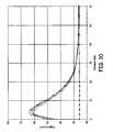
- FIG. 10is a graph showing the temperature of phantom tissue due to operation of the thermal therapy catheter of FIGS. 5-6 as a function of radial distance from the catheter, taken at 10 minutes into a testing procedure using the testing system of FIG. 8 .
- FIG. 11is a graph showing an axial distribution of temperature in phantom tissue relative to the energy-emitting element of the thermal therapy catheter of FIGS. 5-6 during operation of the catheter, taken at 5 minutes into a testing procedure using the testing system of FIG. 8 .
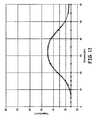
- FIG. 12is a graph showing an axial distribution of temperature in phantom tissue relative to the energy-emitting element of the thermal therapy catheter of FIGS. 5-6 during operation of the catheter, taken at 10 minutes into a testing procedure using the testing system of FIG. 8 .
- FIG. 13is a longitudinal sectional view of the thermal therapy catheter of the present invention.
- FIG. 14is a cross-sectional view of the thermal therapy catheter of the present invention, taken along line 10 — 10 of FIG. 13 .
- FIG. 15is a graph showing the temperature of phantom tissue due to operation of the thermal therapy catheter of FIGS. 13-14 as a function of radial distance from the catheter, taken at 5 minutes into a testing procedure using the testing system of FIG. 8 .
- FIG. 16is a graph showing the temperature of phantom tissue due to operation of the thermal therapy catheter of FIGS. 13-14 as a function of radial distance from the catheter, taken at 10 minutes into a testing procedure using the testing system of FIG. 8 .
- FIG. 17is a graph showing an axial distribution of temperature in phantom tissue relative to the energy-emitting element of the thermal therapy catheter of FIGS. 13-14 during operation of the catheter, taken at 5 minutes into a testing procedure using the testing system of FIG. 8 .
- FIG. 18is a graph showing an axial distribution of temperature in phantom tissue relative to the energy-emitting element of the thermal therapy catheter of FIGS. 13-14 during operation of the catheter, taken at 10 minutes into a testing procedure using the testing system of FIG. 8 .
- FIG. 1is a vertical sectional view of a male pelvic region showing the effect benign prostatic hyperplasia (BPH) has on the urinary organs.
- Urethra 10is a duct leading from neck 22 of bladder 12 , through prostate 14 and out orifice 16 of penis end 18 .
- Benign tumorous tissue growth within prostate 14 around urethra 10causes constriction 20 of urethra 10 , which interrupts the flow of urine from bladder 12 to orifice 16 .
- the tumorous tissue of prostate 14 which encroaches urethra 10 and causes constriction 20can be effectively removed by heating and necrosing the encroaching tumorous tissue.
- a selected volume of tissue of prostate 14should be necrosed without harming adjacent healthy tissues such as urethra 10 , bladder 12 , ejaculatory duct 24 and rectum 26 .
- the realization of this objectiveis enhanced by the microwave antenna-containing catheter of the present invention, which is shown in FIGS. 5-6.
- FIGS. 2-6relate to a thermal therapy catheter of U.S. Pat. No. 6,161,049, which is hereby incorporated by reference.
- FIG. 2shows a side view of a distal end of catheter 28 .
- Catheter 28generally includes multi-port handle 30 , multi-lumen shaft 32 , shaft position retention balloon 34 (FIG. 3 ), connection manifold 35 , cooling system 36 , microwave generating source 38 and thermometry unit 39 .
- Multi-port handle 30includes inflation port 40 , urine drainage port 42 , microwave antenna port 44 , cooling fluid intake port 46 and cooling fluid exit port 48 .
- Ports 40 - 48communicate with corresponding lumens within shaft 32 .
- Handle 30is preferably constructed as a two-piece snap-fit shell, composed of a thermoplastic elastomer or a similar material, with appropriate ports and channels being formed therein for communication with the lumens utilized by the thermal therapy catheter of the present invention.
- Shaft 32is connected to handle 30 at shaft distal end 50 .
- Shaft 32is a multi-lumen, Foley-type urethral catheter shaft.
- Shaft 32which has an outer diameter of about 18 French, includes outer surface 52 , which is generally circular in cross-section as shown in FIG. 5 .
- Shaft 32is both long enough and flexible enough to permit insertion of proximal shaft end 54 through urethra 10 into bladder 12 (FIG. 1 ).
- catheter shaft 32is extruded from a thermoplastic elastomer. Thermoplastic materials are less expensive than medical-grade silicone, and are capable of being thermally processed, thereby obviating the need for adhesive bonding to the silicone, and the relatively long curing times associated therewith.
- FIG. 3is a section view of catheter shaft 32 adjacent proximal end 54 of shaft 32
- FIG. 4is a section view of an intermediate portion of catheter shaft 32
- FIG. 3 and FIG. 4illustrate multi-lobe balloon 71 in its deflated state, for insertion of catheter 28 into urethra 10
- FIG. 5is a section view of catheter shaft 32 taken along line 5 — 5 of FIG. 4
- FIG. 6is a section view of catheter shaft 32 taken along line 6 — 6 of FIG. 3
- Both FIG. 5 and FIG. 6illustrate multi-lobe balloon 71 in its inflated state, for operating to cool the wall of urethra 10 when microwave antenna 74 is energized.
- shaft 32generally includes temperature sensing fiber lumen 56 , microwave antenna lumen 58 , urine drainage lumen 60 , balloon inflation lumen 62 , cooling fluid intake lumen 64 and cooling fluid exhaust lumens 66 and 67 .
- Lumens 56 , 58 , 60 , 62 , 64 , 66 and 67generally extend from distal shaft end 50 to proximal shaft end 54 , and are located within catheter shaft 32 so as to form a catheter wall having uniform thickness throughout the cross-section of shaft 32 , the catheter wall thickness being about 0.008 inches in an exemplary embodiment.
- temperature sensing fiber lumen 56communicates through the wall of shaft 32 through a channel formed in the catheter wall to temperature sensing fiber tube 81 attached to outer surface 52 of shaft 32 .
- Temperature sensing fiber lumen 56 , temperature sensing fiber tube 81 and the channel therebetweenare sized to permit insertion of temperature sensing fiber 69 to monitor the temperature of tissue surrounding shaft 32 when it is inserted into urethra 10 .
- Temperature sensing fiber 69exits handle 30 through port 44 and is connected through manifold 35 to thermometry unit 39 , which calculates temperature based on the optical information provided by temperature sensing fiber 69 .
- Temperature sensing fiber lumen 56has a generally trapezoidal cross-section, and together with the catheter walls on either side between cooling lumens 64 and 67 has an included angle of about 30.5 degrees.
- Multi-lobe balloon 71is attached to outer surface 52 of shaft 32 , preferably by thermal welding or a comparable attachment technique such as adhesive bonding, at one or more points on outer surface 52 .
- Multi-lobe balloon 71is preferably formed of a thermoplastic film wrapped around shaft 32 , such as a polyurethane blown film in an exemplary embodiment. The construction and operation of multi-lobe balloon 71 is described in more detail with respect to FIG. 5 .
- microwave antenna lumen 58is located eccentric to the longitudinal axis of shaft 32 , nearer first side 68 of shaft 32 than second side 72 of shaft 32 .
- the center of antenna lumen 58is offset from the center of shaft 32 towards first side 68 of shaft 32 by 0.007 inches.
- Antenna lumen 58is sealed at a proximal end of shaft 32 by plug 70 A.
- microwave antenna lumen 58communicates with microwave antenna port 44 (FIG. 2 ).
- Microwave antenna 74is permanently positioned within antenna lumen 58 at the proximal end of shaft 32 near balloon 34 .
- Antenna 74is positioned within antenna lumen 58 so as to be generally situated adjacent the diseased tissue of prostate 14 when shaft 32 is properly positioned in urethra 10 with retention balloon 34 anchored at bladder neck 22 .
- Antenna 74includes wound coils carried at the proximal end of coaxial cable 76 .
- the distal end of coaxial cable 76is connected to manifold 35 by a conventional quick-coupling fitting 73 .
- Coaxial cable 76communicates with microwave generating source 38 by connection cable 76 A, which is connected between microwave generating source 38 and manifold 35 .
- microwave antenna 74is an impedance-matched antenna implemented in the manner generally disclosed in U.S. Pat. No.
- antenna lumen 58 and antenna 74it is also preferable for antenna lumen 58 and antenna 74 to have a relatively large radial dimension, about 0.131 inches in an exemplary embodiment, since a larger antenna radius results in lower transmission line losses and also provides greater column stiffness to facilitate insertion of shaft 32 into urethra 10 . More specifically, because microwave antenna lumen 58 is located nearer first side 68 of shaft 32 than second side 70 of shaft 72 , the orientation of shaft 32 in urethra 10 must be controlled to maximize the amount of energy delivered to tumorous tissue and minimize the amount of energy delivered to healthy tissue, such as the rectum, for example.
- microwave antenna 74is designed to effectively transmit 100% of the torque applied to handle 30 on to the tip of shaft 32 at proximal end 54 ; that is, if handle 30 is rotated 20 degrees, the tip of shaft 32 at proximal end 54 also rotates 20 degrees.
- Microwave generating source 38produces up to 100 watts of electrical power in an exemplary embodiment, in a frequency range of 902-928 MHZ, within the FCC-ISM standard range of frequencies.
- antenna 74When antenna 74 is energized by microwave generating source 38 , antenna 74 emits electromagnetic energy which causes heating of tissue within prostate 14 .
- a tip designmay be used at proximal end 54 of catheter shaft 32 as described in U.S. Pat. No. 5,628,770 entitled DEVICES FOR TRANSURETHRAL THERMAL THERAPY, which is hereby incorporated by reference.
- urine drainage lumen 60is positioned adjacent antenna lumen 58 , between antenna lumen 58 and lobe 71 A of multi-lobe balloon 71 .
- Urine drainage lumen 60has a generally trapezoidal cross-section, and together with the catheter walls on either side between cooling lumens 64 and 66 has an included angle of about 30.5 degrees.
- Urine drainage lumen 60communicates with urine drainage port 42 of handle 30 at distal shaft end 50 and defines a drainage path for urine when proximal end 54 of shaft 32 is inserted through urethra 10 into bladder 12 .
- Urinedrains from bladder 12 through urine drainage lumen 60 and out urine drainage port 42 when proximal shaft end 54 is inserted within bladder 12 .
- Retention balloon inflation lumen 62is positioned adjacent antenna lumen 58 , between antenna lumen 58 and lobe 71 B of multi-lobe balloon 71 .
- Balloon inflation lumen 62has a generally trapezoidal cross-section, and together with the catheter walls on either size between cooling lumens 66 and 67 has an included angle of about 29 degrees.
- Balloon inflation lumen 62communicates with inflation port 40 of handle 30 to allow inflation fluid to flow in and out of balloon inflation lumen 62 , and communicates through aperture 88 to inflate retention balloon 34 .
- Cooling fluid intake lumen 64is positioned adjacent to antenna lumen 58 , between antenna lumen 58 and temperature sensing fiber tube 81 between lobes 71 A and 71 C of multi-lobe balloon 71 .
- Cooling fluid intake lumen 64has a generally arcuate cross-section, and extends from distal end 50 to proximal end 54 of shaft 32 .
- Cooling fluid intake lumen 64receives fluid from cooling system 36 to absorb a portion of the microwave energy emitted by the microwave antenna and thereby control the volume of prostatic tissue that is exposed to necrosing levels of heat. Fluid within cooling fluid intake lumen 64 also absorbs a portion of the heat energy generated by microwave energy from adjacent tissues via thermal conduction to avoid thermal damage to those tissues.
- cooling fluid intake lumen 64has an included angle of about 90 degrees.
- Cooling fluid exhaust lumens 66 and 67are positioned circumjacent to antenna lumen 58 , with cooling fluid exhaust lumen 66 being located generally between antenna lumen 58 and lobes 71 A and 71 B of multi-lobe balloon 71 and cooling fluid exhaust lumen 67 being located generally between antenna lumen 58 and lobes 71 B and 71 C of multi-lobe balloon 71 .
- Cooling fluid exhaust lumens 66 and 67have a generally arcuate cross-section, and extend from distal end 50 to proximal end 54 of shaft 32 . Exhaust lumens 66 and 67 provide a return path to cooling system 36 for fluid circulated through intake lumen 64 and multi-lobe balloon 71 .
- Fluid within exhaust lumens 66 and 67absorbs a portion of the microwave energy emitted by the microwave antenna and also absorbs a portion of the heat energy generated by microwave energy from adjacent tissues via thermal conduction, in the manner described above.
- cooling fluid exhaust lumens 66 and 67each have an included angle of about 90 degrees.
- FIG. 6is a section view of catheter shaft 32 taken along line 6 — 6 of FIG. 3 .
- cooling lumens 64 , 66 and 67communicate with the interior of multi-lobe balloon 71 so as to provide cooling fluid to inflate multi-lobe balloon 71 .
- cooling fluid intake lumen 64communicates with the interior of lobe 71 A through aperture 64 A and communicates with the interior of lobe 71 C through aperture 64 B.
- Cooling fluid exhaust lumen 66communicates with the interior of lobe 71 B through aperture 66 A
- cooling fluid exhaust lumen 67communicates with the interior of lobe 71 B through aperture 67 A.
- Cooling fluid intake lumen 64 and exhaust lumens 66 and 67cooperate with cooling system 36 via ports 46 and 48 of handle 30 to provide a selectively controlled flow of fluid through cooling lumens 64 , 66 and 67 during a treatment session.
- cooling fluidflows from cooling system 36 to cooling fluid feed line 94 B and on through port 46 of handle 30 into cooling fluid intake lumen 64 .
- the cooling fluidcontinues to flow under dynamic fluid pressure through apertures 64 A and 64 B to inflate lobes 71 A and 71 C of multi-lobe balloon 71 .
- Cooling fluidflows from lobe 71 B through apertures 66 A and 67 A into cooling fluid exhaust lumens 66 and 67 , and exits shaft 32 at distal end 50 thereof through port 48 of handle 30 , and on through cooling fluid return line 96 B and manifold 35 to cooling system 36 for re-chilling and recirculation.
- Cooling fluid feed line 96 B and return line 96 Bare each provided with a conventional quick-coupling fitting 65 A and 65 B, respectively, which permits catheter 28 to be easily disconnected from cooling system 36 .
- the cooling fluidis deionized water provided by cooling system 36 , chilled to an appropriate temperature so as to maintain the temperature of tissue immediately surrounding catheter shaft 32 at a predetermined value while power is applied from microwave antenna 74 to heat diseased prostate tissue.
- a method of controlling coolant temperature and microwave power to maintain a predetermined tissue temperatureis disclosed in U.S. Pat. No. 6,122,551, entitled “METHOD OF CONTROLLING THERMAL THERAPY,” which is hereby incorporated by reference.
- the wateris pumped at a rate sufficient to provide dynamic pressure to inflate multi-lobe balloon 71 to create an outer balloon diameter of about 24 French, thereby ensuring excellent wall contact with the urethra and enhancing the efficiency of the conductive cooling performed by the circulating cooling fluid flowing in multi-lobe balloon 71 .
- FIG. 7illustrates the pattern of fluid flow through multi-lobe balloon 71 according to an embodiment of the present invention.
- multi-lobe balloon 71is shown in FIG. 7 as “flattened out” in two dimensions; it should be understood that multi-lobe balloon 71 is wrapped around catheter shaft 32 in a final assembly of the present invention, as shown in the cross-sectional views of FIGS. 5 and 6.
- the cross-hashed regions of balloon 71indicate where balloon 71 is thermally welded (or otherwise attached) to the catheter shaft, with the patterns of multi-lobe balloon 71 being formed by heat stamping or an alternative processing method.
- Cooling fluidis circulated into lobe 71 A of multi-lobe balloon 71 through fluid flow aperture 64 A and into lobe 71 C of multi-lobe balloon 71 through fluid flow aperture 64 B.
- the cooling fluidflows under dynamic pressure in the direction indicated by the arrows, through narrow channels 71 D and 71 E into lobe 71 B of multi-lobe balloon 71 , where the fluid exits through fluid flow apertures 66 A and 67 A into exhaust lumens 66 and 67 of shaft 32 .
- the fluid flow path provided by the present inventionensures that the cooling fluid circulates under sufficient dynamic pressure to inflate multi-lobe balloon 71 to a sufficient diameter to provide consistent wall contact with the urethra, such as about 24 French in an exemplary embodiment.
- multi-lobe balloon 71may be formed with more than the three lobes 71 A, 71 B and 71 C illustrated in FIGS. 5 and 6, thereby forming modifying the fluid flow pattern and inflation characteristics of balloon 71 .
- the actual amount of dynamic fluid flow pressuremay be controlled by adjusting a number of parameters, such as the rate at which cooling fluid is pumped from the cooling system, the width of channels 71 D and 71 E, the size of fluid flow apertures 64 A, 64 B, 66 A and 67 A, the width of restricted flow areas elsewhere in the fluid flow path, and other parameters that will be apparent to one skilled in the art.
- dynamic fluid pressureis controlled by an adjustable restrictor located in the fluid flow path proximate to cooling system 36 .
- a thermal therapy catheter as described aboveis designed to enhance the efficiency of treatment of diseased tissue from an adjacent body lumen, particularly for treatment of diseased prostate tissue from a urethrally inserted applicator.
- a multi-lobe balloonis attached around the catheter shaft, with interiors of the balloon lobes in communication with cooling lumens of the catheter, so that circulation of fluid in the cooling lumens dynamically inflates the balloon lobes.
- the radial spacing and shaping of lobes 71 A, 71 B and 71 Care designed to define a fluid chamber that corresponds to the generally triangular cross-sectional geometry of the urethra.
- the balloon lobesmore readily come into intimate contact with the wall of the urethra, and the cooling fluid circulating in the balloon lobes is thereby able to efficiently conduct heat away from the urethral wall tissue to preserve the urethra while delivering microwave energy to heat prostate tissue to high temperatures (above about 45° C.) for a sufficient time to necrose the targeted prostate tissue.
- the balloon wall thicknessis about 0.002 inches.
- the inflatable nature of the multi-lobe cooling balloonallows the catheter to be easily inserted when the balloon is not inflated (with the catheter shaft having a relatively small diameter of about 18 French) while providing the ability to firmly contact the urethral wall to enhance cooling when the balloon is inflated, up to a diameter of about 24 French in one embodiment.
- temperature sensing fiber lumen 56 , urine drainage lumen 60 and balloon inflation lumen 62are all formed with generally trapezoidal cross-sections, so as to minimize the included angle of each of these lumens. As a result, the included angle of cooling lumens 64 , 66 and 67 is maximized, improving the efficiency of urethral cooling.
- cooling lumens 64 , 66 and 67which ensures that sufficient cooling of the urethral wall occurs at the seams of multi-lobe balloon 71 in addition to the inflated lobes of the balloon.
- Cooling lumens 64 , 66 and 67also extend along the entire length of the microwave antenna to provide internal cooling of the catheter and thereby ensure that the thermoplastic material of the catheter shaft is not melted by the resistive heating produced by the antenna and the heating produced by absorption of microwave energy by the catheter walls.
- Temperature sensing fiber 69 within temperature sensing fiber tube 81is also strategically placed in the catheter design. Temperature sensing fiber tube 81 is located in the seam between lobes 71 A and 71 C of multi-lobe balloon 71 , so as to minimize its effect on the outer perimeter shape of the catheter. In addition, the location of temperature sensing fiber tube 81 also ensures that cooling lumen 64 is positioned directly between temperature sensing fiber 69 and the microwave antenna positioned in antenna lumen 58 .
- the resistive heating produced by the microwave antennahas no appreciable effect on the temperature reading obtained by temperature sensing fiber 69 ; the only variables that affect the temperature reading are the actual temperature of tissue immediately adjacent temperature sensing fiber tube 81 and the temperature of the cooling fluid circulating through cooling lumen 64 .
- the cooling fluid temperaturemay be compensated for by the thermometry unit to yield an accurate value for the actual tissue temperature, which is useful information for controlling the thermal therapy procedure.
- the catheter design of the present inventionis able to necrose a substantial portion of the prostate while controlling temperatures to protect healthy tissues such as the urethral wall and the rectum, with a treatment time of approximately 30 minutes or less and no need for anesthesia.
- the systemtherefore offers an attractive therapy option for treating tissue disease such as BPH, with excellent long-term results and a low risk of morbidity or other side effects.
- FIG. 8is a perspective view of testing system 98 in which basic performance characteristics concerning energy and temperature distribution patterns capable of being achieved by the catheter of FIGS. 5-6 are demonstrated.
- proximal end 54 of catheter 28is inserted into a block of gelatinous phantom tissue medium 100 composed primarily of distilled water, ethylene glycol and sodium chloride.
- Tissue medium 100is held in place by a cubicle container having six transparent, plastic walls.
- Catheter 28is positioned in the tissue medium 100 by vertically inserting catheter 28 through a pre-positioned channel (not shown) in tissue medium 100 so that catheter 28 is located in the center of tissue medium 100 .
- Temperature sensors R 1 , R 2 , R 3 and R 4are located within four pre-positioned channels (not shown) in tissue medium 100 in a common plane, which is transverse to a vertical plane defined by catheter 28 .
- Catheter 28is positioned relative to temperature sensors R 1 -R 4 such that a midpoint of microwave antenna 74 is adjacent to temperature sensors R 1 -R 4 .
- Temperature sensors R 1 -R 4are capable of radial movement in unison away from catheter 28 , with a starting position of each sensor being located about 0.5 cm from catheter 28 .
- Temperature sensors R 2 and R 3are located on opposite sides of catheter 28 and move radially away from each other.
- Temperature sensors R 1 and R 4are also located on opposite sides of catheter 28 and move radially away from each other. Through this configuration, temperature sensors R 1 -R 4 are equally radially spaced from each other around catheter 28 .
- Temperature sensors A 1 , A 2 , A 3 and A 4are located within four pre-positioned channels (not shown) in tissue medium 100 .
- Temperature sensors A 1 -A 4are located adjacent to a longitudinal axis of catheter 28 , and are capable of axial movement in unison along the length of catheter 28 .
- Each temperature sensor A 1 -A 4is located an axial distance of 0.5 cm from catheter 28 .
- Temperature sensors A 1 -A 4are equally radially spaced around catheter 28 in order to capture temperature readings on discrete sides of catheter 28 .
- temperature sensors A 1 -A 4are aligned in a common horizontal plane located below proximal end 54 of catheter 28 .
- temperature sensors A 1 -A 4move axially upwards along the length of antenna 74 of catheter 28 .
- FIG. 8Ashows a cross-sectional view of the testing system of FIG. 8 taken along line 9 — 9 .
- FIG. 8Ashows the orientation of the temperature sensors R 1 -R 4 and A 1 -A 4 relative to catheter 28 and microwave antenna 74 . Temperature sensors R 1 -R 4 are shown in their starting position for a test phase. The directions of movement for temperature sensors R 1 -R 4 are illustrated by the arrows in FIG. 8 A.
- An exemplary testing procedure using testing system 98is composed of multiple testing phases, each testing phase lasting approximately 1.2 minutes. Testing phases may be performed at 5 and 10 minutes during a testing procedure, for example.
- a testing phasethe movement of the temperature sensors R 1 -R 4 and A 1 -A 4 , and the recording of temperatures in tissue medium 100 are computer controlled by testing system 98 .
- tissue medium 100typically has a temperature of about 25° C.
- catheter 28typically has a temperature of about 25.3° C.
- Microwave antenna 74 of catheter 28is energized to a power level of 30 watts at a frequency of 927 Hertz at the start of a testing procedure.
- temperature sensors R 1 -R 4begin at their start positions 0.5 cm from catheter 28 and move in radial directions shown in FIG. 8A away from catheter 28 to a distance of about 60 mm. As temperature sensors R 1 -R 4 move through tissue medium 100 , the temperature sensors measure the temperature of tissue medium 100 . A temperature recording is taken at 2.5 mm increments in tissue medium 100 . After a testing phase is completed, the temperature sensors R 1 -R 4 are repositioned in their start positions in preparation for the following testing phase. Temperature sensors R 1 -R 4 move at a constant rate of about 0.8 mm per second during each testing phase of the testing procedure.
- Temperature sensors A 1 -A 4begin each testing phase at a location proximal of antenna 74 . Throughout a testing phase, temperature sensors A 1 -A 4 maintain a constant radial distance of 0.5 cm away from catheter 28 as temperature sensors A 1 -A 4 move adjacent to the longitudinal axis of catheter 28 . Temperature sensors A 1 -A 4 pass along a section of catheter 28 containing microwave antenna 74 during a testing phase, and the temperature sensors end each testing phase at a location distal of microwave antenna 74 . Temperature sensors A 1 -A 4 record a temperature of tissue medium 100 every 2.5 mm during a testing phase. Once a testing phase is complete, temperature sensors A 1 -A 4 are repositioned in their starting locations in preparation for a following testing phase. Temperature sensors A 1 -A 4 move at a constant rate of about 0.8 mm per second during each testing phase of the testing procedure, in coordination with the movement of sensor R 1 -R 4 .
- FIGS. 9-10show temperature recordings of temperature sensors R 1 -R 4 in comparison to the distances of temperature sensors R 1 -R 4 from catheter 28 during a complete testing procedure.
- FIGS. 9-10each represent temperature and distance data from a single testing phase.
- the vertical axes of FIGS. 9-16correspond to the temperature of tissue medium 100
- the horizontal axescorrespond to the radial distance away from catheter 28 of temperature sensors R 1 -R 4 .
- temperature recordings of R 1are shown by diamond marks
- temperature recordings of R 2are shown by square marks
- temperature recordings of R 3are shown by triangle marks
- temperature recordings of R 4are shown by “x” marks.
- FIGS. 9-10show that temperature sensors R 1 -R 4 record substantially similar temperatures at similar locations in tissue medium 100 throughout each testing phase.
- FIGS. 9-10illustrate that catheter 28 produces a radially symmetrical temperature distribution in tissue medium 100 .
- FIGS. 9-10show that temperature of tissue medium 100 steadily increases during a testing procedure, and that a similar temperature distance pattern is developed during each testing phase.
- FIGS. 9-10show the temperature recordings of temperature sensors R 1 -R 4 during a testing phase performed at 5 and 10 minutes, respectively, into the testing procedure.
- FIGS. 9-10show an initial temperature increase as temperature sensors R 1 -R 4 move radially away from catheter 28 .
- temperatures sensors R 1 -R 4After reaching peak temperatures ranging from about 40° C. to 70° C. (with the higher peak temperatures occurring after phantom tissue medium 100 has been exposed to the emitted energy for a longer period of time), temperatures sensors R 1 -R 4 show a steady decrease in temperature as temperature sensors R 1 -R 4 move further away from catheter 28 .
- FIGS. 9-10illustrate that temperature sensors R 1 -R 4 are recording generally similar temperatures at similar distances away from catheter 28 for each respective test, with only slightly lower temperatures being measured in tissue adjacent to balloon lobes 71 A and 71 C, as reflected by the curves for sensors R 3 and R 4 .
- FIGS. 9-10show that catheter 28 is generating a substantially uniform temperature distribution radially throughout tissue medium 100 after microwave antenna 74 has been energized.
- FIGS. 11-12show the temperature recordings of temperature sensors A 1 -A 4 in comparison to the positions of temperature sensors A 1 -A 4 along the length of catheter 28 during a complete testing procedure.
- FIGS. 11-12each represent temperature and distance data from a single testing phase, at 5 and 10 minutes into a testing procedure, respectively.
- the vertical axes of FIGS. 11-12correspond to the temperature of tissue medium 100
- the horizontal axescorrespond to the axial distance along catheter 28 of temperature sensors A 1 -A 4 .
- temperature recordings of A 1are shown by diamond marks
- temperature recordings of A 2are shown by square marks
- temperature recordings of A 3are shown by triangle marks
- temperature recordings of A 4are shown by “x” marks.
- FIGS. 11-12show that temperature sensors A 1 -A 4 record substantially similar temperatures at similar locations along catheter 28 in tissue medium 100 throughout each testing phase.
- FIGS. 11-12illustrate that catheter 28 produces a generally radially symmetrical temperature distribution along catheter 28 , with the intensity of energy and therefore the measured temperature increasing as a function of time.
- FIGS. 9-10display the temperature data recorded by temperature sensors R 1 -R 4 throughout a complete testing procedure. Note that FIGS. 9-10 show a similar pattern for temperature variation (a gradual increase and then a decrease) as temperature sensors R 1 -R 4 move radially away from catheter 28 . Also note that temperature sensors R 1 -R 4 are recording similar temperatures at similar distances away from the catheter, even though temperature sensors R 1 -R 4 are moving in four separate directions relative to four different sides of catheter 28 . Thus, FIGS. 9-10 illustrate that catheter 28 generates a radially symmetrical temperature distribution in tissue medium 100 surrounding catheter 28 .
- FIGS. 11-12display the temperature data recorded by temperature sensors A 1 -A 4 throughout a complete testing procedure. Similar to temperature sensors R 1 -R 4 , temperature sensors A 1 -A 4 show a symmetrical heating distribution in all radial directions from catheter 28 in tissue medium 100 . Thus, FIGS. 9-10 in combination with FIGS. 11-12 confirm that catheter 28 generates a generally radially symmetrical heating pattern throughout tissue medium 100 .
- Microwave thermal therapysuch as is described above may be further enhanced with the present invention to maximize the amount of energy emitted toward targeted tissues while controlling the energy emitted toward certain healthy tissues to avoid thermal damage to those tissues.
- the rectumfor example, contains tissue that is susceptible to thermal damage.
- the radial extent of necrosis produced by a catheter emitting a symmetrical heating patternis limited by the close proximity of the rectum relative to the urethra.
- a control algorithmmay be utilized to limit power to the microwave antenna so as to protect the rectum from thermal damage, modifying the thermal treatment catheter to restrict the amount of energy delivered toward the rectum enhances the ability to effectively necrose the greatest possible volume of diseased prostate tissue without thermally damaging the rectum.
- FIGS. 13-18A catheter system achieving this objective and associated test results are disclosed in FIGS. 13-18.
- Clinicians using the nonuniform heat-distributing catheter system of the present inventioncan position the catheter within a body cavity in such a manner that tissues designated for treatment are exposed to high amounts of thermal energy while healthy tissues are exposed to lower, non-damaging amounts of thermal energy.
- FIG. 13is a side view of one preferred embodiment of a catheter of the present invention.
- Catheter 104incorporates all of the previously-described features of catheter 28 shown FIGS. 2-7.
- catheter 104includes metal strip 102 composed of a material such as brass, for example, located in cooling lumen 64 of catheter 104 .
- Metal strip 102has a length at least corresponding to the length of microwave antenna 74 , and serves to alter the microwave energy pattern emitted from microwave antenna 74 of catheter 104 in a way that reduces heating in the direction of strip 102 .
- incorporating strip 102 in catheter 104has been shown to change the temperature distribution pattern of catheter 104 , since the temperature of the tissue surrounding catheter 104 is directly related to the amount of energy delivered to the tissue.
- catheter 104With strip 102 in place, catheter 104 has two treatment zones, a preferential heating zone and a non-preferential heating zone.
- the preferential heating zoneexperiences temperatures significantly higher than those experienced in the non-preferential heating zone.
- the non-preferential heating zonecorresponds to the rectal tissue region of the patient.
- FIG. 14is a sectional view of catheter 104 , taken along line 14 - 14 of FIG. 13 .
- metal strip 102is positioned inside cooling lumen 64 of catheter 104 so that it is adjacent to microwave antenna 74 .
- Metal strip 102is approximately 2 inches long, 0.08 inches wide and 0.0053 inches in height.
- Metal strip 102has a length slightly longer than microwave antenna 74 and a width slightly less than the radial width of cooling lumen 64 .
- Strip 102has a concave shape, which is formed by bending strip 102 over a mandrel after cutting strip 102 to size.
- the concave shape of metal strip 102allows the strip 102 to be held in place within cooling lumen 64 by friction at three points of contact on the walls of cooling lumen 64 .
- An end of metal strip 102is secured to proximal end 54 of catheter 104 with an adhesive to prevent metal strip 102 from moving within cooling lumen 64 .
- the concave shape of metal strip 102also permits the cooling fluid to pass through cooling lumen 64 without interference from strip 102 . Also, metal strip 102 does not interfere with fluid flow through the cooling lumen ports 64 A and 64 B.
- the catheteris placed in testing system 98 as shown in FIG. 8 .
- the same parameters and testing procedure as described previously for catheter 28is used to test catheter 104 , with the individual testing phases performed at 5 and 10 minutes into the testing procedure.
- FIGS. 15-16show temperature recordings of temperature sensors R 1 -R 4 in comparison to the distances of temperature sensors R 1 -R 4 from catheter 104 during a complete testing procedure.
- FIGS. 15-16each represent temperature and distance data from a single testing phase.
- the vertical axes of FIGS. 15-16correspond to the temperature of tissue medium 100
- the horizontal axescorrespond to the radial distance away from catheter 104 of temperature sensors R 1 -R 4 .
- temperature recordings of R 1are shown by diamond marks
- temperature recordings of R 2are shown by square marks
- temperature recordings of R 3are shown by triangle marks
- temperature recordings of R 4are shown by “x” marks.
- FIGS. 15-16show that temperature sensors R 1 and R 2 record substantially dissimilar temperatures from the temperatures recorded by temperature sensors R 3 and R 4 at similar locations in tissue medium 100 throughout each testing phase.
- FIGS. 15-16illustrate that catheter 104 produces a radially asymmetrical temperature distribution throughout tissue medium 100 , and specifically, that catheter 104 generates two distinct heating zones in the tissue medium—a preferential heating zone and a non-preferential heating zone. The generation of two distinct heating zones is caused by metal strip 102 , which attenuates microwave energy in the direction of the non-preferential heating zone.
- FIGS. 15-16also illustrate that the temperature distribution throughout the preferential heating zone is generally uniform, and that the temperature distribution throughout the non-preferential heating zone is also generally uniform. Over the course of the complete testing procedure, FIGS. 15-16 indicate that the temperature of tissue medium 100 is steadily increased, and that temperature sensors R 1 -R 4 record similarly shaped temperature-distance patterns during each testing phase.
- FIG. 15shows the temperature recordings of temperature sensors R 1 -R 4 during a testing phase performed at 5 minutes into a testing procedure. Similar to FIG. 27, FIG. 28 shows that temperature sensors R 1 and R 2 record significantly higher temperatures than temperature sensors R 3 and R 4 in regions of tissue medium 100 which experience a substantial thermal change due to the energy generated by microwave catheter 104 .
- the higher temperatures recorded by R 1 and R 2are due to the fact that R 1 and R 2 are located in the preferential heating zone of catheter 104 , while R 3 and R 4 are located in the non-preferential heating zone of catheter 104 .
- FIG. 15also illustrates that temperature sensors R 1 and R 2 experience similar temperatures at similar radial distances, and temperature sensors R 3 and R 4 experience similar temperatures at similar radial distances.
- FIG. 15indicates that temperatures throughout the preferential heating zone are generally uniform, and that temperatures throughout the non-preferential heating zone are generally uniform. Temperature sensors in the preferential heating zone, R 1 and R 2 , experience temperatures approximately 10° higher than temperature sensors R 3 and R 4 in the non-preferential heating zone.
- FIG. 16shows the temperatures recorded by temperature sensors R 1 -R 4 during a testing phase performed at 10 minutes into a testing procedure.
- FIG. 16illustrates that temperature sensors R 1 and R 2 experience significantly higher temperatures than temperature sensors R 3 and R 4 .
- Temperature sensors in the preferential heating zone, R 1 and R 2once again experience temperatures about 10° 24 higher than temperature sensors R 3 and R 4 in the non-preferential heating zone, with peak temperatures being higher than the peak temperatures of the previous testing phase.
- FIGS. 15-16the temperature variation between R 1 , R 2 and R 3 , R 4 is substantial for a distance from 0 to approximately 30 mm away from catheter 104 . Beyond 30 mm from catheter 104 , temperature sensors R 1 -R 4 experience similar temperatures due to the decreased amount of energy delivered to the phantom tissue medium at those distances.
- FIGS. 15-16illustrate that catheter 104 does not generate a radially symmetrical heating pattern in tissue medium 100 , but instead, creates two distinct temperature zones—a preferential heating zone and a non-preferential heating zone, with the non-preferential heating zone being exposed to substantially lower amounts of thermal energy. The placement of metal strip 102 in catheter 104 creates the two distinct heating zones.
- Metal strip 102attenuates microwave energy in the direction of the non-preferential heating zone, thereby decreasing the thermal energy delivered into the non-preferential heating zone during a treatment procedure.
- FIGS. 15-16also illustrate that the temperature distribution throughout the preferential heating zone is generally uniform, and the temperature distribution throughout the non-preferential heating zone is also generally uniform.
- FIGS. 17-18show temperature recordings of temperature sensors A 1 -A 4 in comparison to the positions of temperature sensors A 1 -A 4 along catheter 104 during a complete testing procedure.
- FIGS. 17-18each represent temperature and distance data from a single testing phase.
- the vertical axes of FIGS. 17-18correspond to the temperature of tissue medium 100
- the horizontal axescorrespond to the axial position along catheter 104 of temperature sensors A 1 -A 4 .
- temperature recordings of A 1are shown by diamond marks
- temperature recordings of A 2are shown by square marks
- temperature recordings of A 3are shown by triangle marks
- temperature recordings of A 4are shown by “x” marks.
- FIGS. 17-18show that temperature sensor A 1 records substantially higher temperatures and temperature sensor A 3 records substantially lower temperatures than temperature sensors A 2 and A 4 at similar locations along catheter 104 in tissue medium 100 throughout each testing phase.
- FIGS. 17-18illustrate that catheter 104 produces a radially asymmetrical temperature distribution along catheter 104 .
- FIGS. 17-18indicate that the temperature of tissue medium 100 is steadily increased, and that temperature sensors A 1 -A 4 record similar temperature-distance patterns during each testing phase.
- FIG. 17illustrates the temperature recordings of temperature sensors A 1 -A 4 during a testing phase performed at 5 minutes into a testing procedure.
- FIG. 17shows that the temperatures recorded by temperature sensors A 1 -A 4 gradually increase and then decrease over the course of a testing phase. This gradual increase and decrease in recorded temperatures corresponds to the movement of temperature sensors A 1 -A 4 along the length of catheter 104 .
- the temperature increasecorresponds to temperature sensors A 1 -A 4 sensing increased temperatures in tissue medium 100 as they move along the length of the energized microwave antenna 74 of catheter 104 .
- the temperature decreasecorresponds to the region of tissue medium 100 which is not adjacent to microwave antenna 74 and thus is not exposed to as much thermal energy as tissue directly adjacent to antenna 74 .
- FIG. 17illustrates the temperature recordings of temperature sensors A 1 -A 4 during a testing phase performed at 5 minutes into a testing procedure.
- FIG. 17shows that the temperatures recorded by temperature sensors A 1 -A 4 gradually increase and then decrease over the course of a testing phase. This gradual increase
- temperature sensor A 1experiences substantially higher temperatures and temperature sensor A 3 experiences substantially lower temperatures than temperature sensors A 2 and A 4 as the temperature of tissue medium 100 increases.
- Temperature sensor A 3experiences lower temperatures because it is located in the non-preferential heating zone of catheter 104 , due to microwave attenuation by metal strip 102 .
- temperature sensor A 1is located in the preferential heating zone of catheter 104 , and thus, experiences higher temperatures.
- Temperature sensors A 2 and A 4experience similar temperatures at similar axial distances, with the temperatures experienced being between the temperatures experienced by temperature sensors A 1 and A 3 .
- FIG. 18corresponds to the temperature recordings of temperature sensors A 1 -A 4 during a testing phase performed at 10 minutes into a testing procedure.
- FIG. 18, similar to FIG. 17,illustrates a temperature difference between temperature sensors A 1 and A 3 and temperature sensors A 2 and A 4 .
- Temperature sensor A 1 in the preferential heating zoneexperiences substantially higher temperatures than temperature sensor A 3 , which is located in the non-preferential heating zone.
- Temperature sensors A 2 and A 4experience similar temperatures, with those temperatures being between the temperatures experienced by temperatures sensors A 1 and A 3 .
- FIG. 18also illustrates that the temperature distribution is axially uniform throughout the preferential heating zone, and also that the temperature distribution is axially uniform throughout the non-preferential heating zone.
- the peak temperatures experienced by temperature sensors A 1 -A 4 in tissue medium 100are greater than those shown in FIG. 17 .
- FIGS. 15-16display the temperature data recorded by temperature sensors R 1 -R 4 throughout a complete testing procedure.
- FIGS. 15-16each show a similar pattern for temperature variation (a gradual increase and then decrease in temperatures of tissue medium 100 ) as temperature sensors R 1 -R 4 move radially away from catheter 104 .
- FIGS. 15-16show that catheter 104 does not heat tissue medium 100 symmetrically in radial directions. Instead, two heating zones are generated by catheter 104 —a preferential heating zone and a non-preferential heating zone. The preferential heating zone experiences substantially higher temperatures than the non-preferential heating zone. However, the temperature distributions within the preferential heating zone and the non-preferential heating zones are generally uniform.
- FIGS. 17-18display the temperature data recorded by temperature sensors A 1 -A 4 throughout a complete testing procedure. Similar to temperature sensors R 1 -R 4 , temperature sensors A 1 -A 4 show a radially asymmetrical heating distribution in tissue medium 100 . Thus, FIGS. 17-18 in combination with FIGS. 15-16 con firm that catheter 104 generates two zones of thermal energy within tissue medium 100 , and that one of the heating zones experiences substantially greater temperatures than the other zone. The generation of the two distinct heating zones is a result of metal strip 102 attenuating microwave energy in the direction of the non-preferential heating zone.
- the present inventionis a simple, inexpensive modification to a microwave thermal treatment catheter system that produces an asymmetrical heating pattern, thereby enabling a clinician to utilize the catheter in such a manner as to expose tissues in a first selected region to necrosing levels of energy at a large depth and to expose tissues in a second selected region to necrosing levels of energy at a smaller depth, to protect healthy tissues adjacent the second selected region from thermal damage.
- the inventionis particularly useful for treatment of a prostate from a urethral catheter, employed to necrose prostate tissue in a region anterior to the urethra (opposite the rectum) to a first depth and to necrose prostate tissue in a region posterior to the urethra (adjacent the rectum) to a second depth, less than the first depth, without thermally damaging the rectum.
Landscapes
- Health & Medical Sciences (AREA)
- Surgery (AREA)
- Life Sciences & Earth Sciences (AREA)
- Biomedical Technology (AREA)
- Medical Informatics (AREA)
- Nuclear Medicine, Radiotherapy & Molecular Imaging (AREA)
- Electromagnetism (AREA)
- Engineering & Computer Science (AREA)
- Physics & Mathematics (AREA)
- Heart & Thoracic Surgery (AREA)
- Otolaryngology (AREA)
- Molecular Biology (AREA)
- Animal Behavior & Ethology (AREA)
- General Health & Medical Sciences (AREA)
- Public Health (AREA)
- Veterinary Medicine (AREA)
- Thermotherapy And Cooling Therapy Devices (AREA)
- Radiation-Therapy Devices (AREA)
Abstract
Description
Claims (22)
Priority Applications (1)
| Application Number | Priority Date | Filing Date | Title |
|---|---|---|---|
| US10/115,158US6740108B1 (en) | 2001-04-05 | 2002-04-03 | Thermal treatment catheter having preferential asymmetrical heating pattern |
Applications Claiming Priority (2)
| Application Number | Priority Date | Filing Date | Title |
|---|---|---|---|
| US28189101P | 2001-04-05 | 2001-04-05 | |
| US10/115,158US6740108B1 (en) | 2001-04-05 | 2002-04-03 | Thermal treatment catheter having preferential asymmetrical heating pattern |
Publications (1)
| Publication Number | Publication Date |
|---|---|
| US6740108B1true US6740108B1 (en) | 2004-05-25 |
Family
ID=32314266
Family Applications (1)
| Application Number | Title | Priority Date | Filing Date |
|---|---|---|---|
| US10/115,158Expired - LifetimeUS6740108B1 (en) | 2001-04-05 | 2002-04-03 | Thermal treatment catheter having preferential asymmetrical heating pattern |
Country Status (1)
| Country | Link |
|---|---|
| US (1) | US6740108B1 (en) |
Cited By (38)
| Publication number | Priority date | Publication date | Assignee | Title |
|---|---|---|---|---|
| US20050025830A1 (en)* | 2003-06-23 | 2005-02-03 | Technische Universiteit Eindhoven | Drug delivery device comprising an active compound and method for releasing an active compound from a drug delivery device |
| US20090212046A1 (en)* | 2006-07-14 | 2009-08-27 | Katsuyoshi Tabuse | Microwave induction heating device |
| US7826904B2 (en) | 2006-02-07 | 2010-11-02 | Angiodynamics, Inc. | Interstitial microwave system and method for thermal treatment of diseases |
| US20100286679A1 (en)* | 2009-04-27 | 2010-11-11 | Michael Hoey | Systems and Methods for Prostate Treatment |
| US8123705B2 (en) | 2005-10-06 | 2012-02-28 | Boston Scientific Scimed, Inc. | Adjustable profile probe |
| EP2452647A1 (en)* | 2010-11-12 | 2012-05-16 | Vivant Medical, Inc. | Apparatus, system and method for performing an electrosurgical procedure |
| US8512329B2 (en) | 2008-08-25 | 2013-08-20 | Covidien Lp | Microwave antenna assembly having a dielectric body portion with radial partitions of dielectric material |
| EP2732832A2 (en) | 2012-11-14 | 2014-05-21 | Universitair Medisch Centrum Groningen (UMCG) | Drug delivery device comprising an active compound and a thermo-sensitive polymeric material |
| US9044254B2 (en) | 2012-08-07 | 2015-06-02 | Covidien Lp | Microwave ablation catheter and method of utilizing the same |
| WO2015079322A2 (en) | 2013-11-26 | 2015-06-04 | Newuro, B.V. | Bladder tissue modification for overactive bladder disorders |
| US9121774B2 (en) | 2012-06-22 | 2015-09-01 | Covidien Lp | Microwave thermometry for microwave ablation systems |
| US9198708B2 (en) | 2010-03-25 | 2015-12-01 | Nxthera, Inc. | Systems and methods for prostate treatment |
| US9333035B2 (en) | 2012-09-19 | 2016-05-10 | Denervx LLC | Cooled microwave denervation |
| US9345507B2 (en) | 2008-11-06 | 2016-05-24 | Nxthera, Inc. | Systems and methods for treatment of BPH |
| US9610122B2 (en) | 2013-03-29 | 2017-04-04 | Covidien Lp | Step-down coaxial microwave ablation applicators and methods for manufacturing same |
| USRE46362E1 (en) | 2009-11-16 | 2017-04-11 | Covidien Lp | Twin sealing chamber hub |
| US9895185B2 (en) | 2011-09-13 | 2018-02-20 | Nxthera, Inc. | Systems and methods for prostate treatment |
| US9968395B2 (en) | 2013-12-10 | 2018-05-15 | Nxthera, Inc. | Systems and methods for treating the prostate |
| US10179029B2 (en) | 2014-01-24 | 2019-01-15 | Denervx LLC | Cooled microwave denervation catheter configuration and method |
| US10182865B2 (en) | 2010-10-25 | 2019-01-22 | Medtronic Ardian Luxembourg S.A.R.L. | Microwave catheter apparatuses, systems, and methods for renal neuromodulation |
| US10194970B2 (en) | 2013-12-10 | 2019-02-05 | Nxthera, Inc. | Vapor ablation systems and methods |
| US10335222B2 (en) | 2012-04-03 | 2019-07-02 | Nxthera, Inc. | Induction coil vapor generator |
| US10342593B2 (en) | 2015-01-29 | 2019-07-09 | Nxthera, Inc. | Vapor ablation systems and methods |
| US10363094B2 (en) | 2011-04-08 | 2019-07-30 | Covidien Lp | Flexible microwave catheters for natural or artificial lumens |
| US10376309B2 (en) | 2016-08-02 | 2019-08-13 | Covidien Lp | Ablation cable assemblies and a method of manufacturing the same |
| US10390881B2 (en) | 2013-10-25 | 2019-08-27 | Denervx LLC | Cooled microwave denervation catheter with insertion feature |
| US10610294B2 (en) | 2012-04-22 | 2020-04-07 | Newuro, B.V. | Devices and methods for transurethral bladder partitioning |
| US10610281B2 (en) | 2008-11-06 | 2020-04-07 | Boston Scientific Scimed, Inc. | Systems and methods for treatment of prostatic tissue |
| US10624697B2 (en) | 2014-08-26 | 2020-04-21 | Covidien Lp | Microwave ablation system |
| US10702327B2 (en) | 2015-05-13 | 2020-07-07 | Boston Scientific Scimed, Inc. | Systems and methods for treating the bladder with condensable vapor |
| US10751107B2 (en) | 2017-01-06 | 2020-08-25 | Boston Scientific Scimed, Inc. | Transperineal vapor ablation systems and methods |
| US10772670B2 (en) | 2013-03-14 | 2020-09-15 | Boston Scientific Scimed, Inc. | Systems and methods for treating prostate cancer |
| US10813691B2 (en) | 2014-10-01 | 2020-10-27 | Covidien Lp | Miniaturized microwave ablation assembly |
| US10813692B2 (en) | 2016-02-29 | 2020-10-27 | Covidien Lp | 90-degree interlocking geometry for introducer for facilitating deployment of microwave radiating catheter |
| US11065053B2 (en) | 2016-08-02 | 2021-07-20 | Covidien Lp | Ablation cable assemblies and a method of manufacturing the same |
| US11197715B2 (en) | 2016-08-02 | 2021-12-14 | Covidien Lp | Ablation cable assemblies and a method of manufacturing the same |
| US11246640B2 (en) | 2016-12-21 | 2022-02-15 | Boston Scientific Scimed, Inc. | Vapor ablation systems and methods |
| US12440258B2 (en) | 2023-11-20 | 2025-10-14 | Boston Scientific Scimed, Inc. | Systems and methods for treating prostate cancer |
Citations (39)
| Publication number | Priority date | Publication date | Assignee | Title |
|---|---|---|---|---|
| US3228400A (en) | 1962-12-03 | 1966-01-11 | Thomas A Armao | Cryogenic capsule probes |
| US4204549A (en) | 1977-12-12 | 1980-05-27 | Rca Corporation | Coaxial applicator for microwave hyperthermia |
| DE3011322A1 (en) | 1979-03-23 | 1980-09-25 | Rca Corp | DEVICE FOR MICROWAVE TREATMENT OF BODY TISSUE |
| US4573966A (en) | 1981-11-24 | 1986-03-04 | Schneider Medintag Ag | Method and apparatus for removing and/or enlarging constricted areas in vessels conducting body fluids |
| US4583556A (en) | 1982-12-13 | 1986-04-22 | M/A-Com, Inc. | Microwave applicator/receiver apparatus |
| US4601296A (en) | 1983-10-07 | 1986-07-22 | Yeda Research And Development Co., Ltd. | Hyperthermia apparatus |
| US4612940A (en) | 1984-05-09 | 1986-09-23 | Scd Incorporated | Microwave dipole probe for in vivo localized hyperthermia |
| DE3707921A1 (en) | 1986-03-12 | 1987-09-17 | Olympus Optical Co | Medical treatment device |
| US4700716A (en) | 1986-02-27 | 1987-10-20 | Kasevich Associates, Inc. | Collinear antenna array applicator |
| EP0246176A2 (en) | 1986-05-12 | 1987-11-19 | Biodan Medical Systems Ltd | Catheter and probe |
| DE3730494A1 (en) | 1986-09-16 | 1988-03-24 | Olympus Optical Co | THERMOTHERAPY DEVICE |
| US4825880A (en) | 1987-06-19 | 1989-05-02 | The Regents Of The University Of California | Implantable helical coil microwave antenna |
| US4832023A (en) | 1987-06-03 | 1989-05-23 | Mcm Laboratories, Inc. | Method and apparatus for reducing blockage in body channels |
| US4841988A (en) | 1987-10-15 | 1989-06-27 | Marquette Electronics, Inc. | Microwave hyperthermia probe |
| US4913142A (en) | 1985-03-22 | 1990-04-03 | Massachusetts Institute Of Technology | Catheter for laser angiosurgery |
| EP0370890A1 (en) | 1988-11-21 | 1990-05-30 | Technomed Medical Systems | Apparatus for the surgical treatment of tissues by hyperthermia, preferably the prostate, equipped with heat protection means preferably comprising means forming radioreflecting screen |
| US5061267A (en) | 1987-12-22 | 1991-10-29 | Andreas Zeiher | Balloon catheter for rechanneling stenoses in body passages, in particular of coronary and peripheral arterial vessels |
| JPH0428377A (en) | 1990-05-25 | 1992-01-30 | Olympus Optical Co Ltd | Probe for thermotherapy |
| US5097845A (en) | 1987-10-15 | 1992-03-24 | Labthermics Technologies | Microwave hyperthermia probe |
| US5151100A (en) | 1988-10-28 | 1992-09-29 | Boston Scientific Corporation | Heating catheters |
| WO1993001752A1 (en) | 1991-07-19 | 1993-02-04 | Technomed International | Use of composite piezoelectric transducer for ultrasonic therapy apparatus |
| US5213097A (en) | 1989-10-24 | 1993-05-25 | Zewa Ag | Apparatus for the treatment of diseases of the walls of opening or cavities of the body |
| WO1993020767A1 (en) | 1992-04-13 | 1993-10-28 | Ep Technologies, Inc. | Articulated unidirectional microwave antenna systems for cardiac ablation |
| WO1993025136A2 (en) | 1992-06-05 | 1993-12-23 | Chin Albert K | Method and apparatus for prostatic treatment |
| US5301687A (en) | 1991-06-06 | 1994-04-12 | Trustees Of Dartmouth College | Microwave applicator for transurethral hyperthermia |
| EP0597463A2 (en) | 1992-11-13 | 1994-05-18 | DORNIER MEDICAL SYSTEMS, Inc. | Thermotherapiesonde |
| US5330518A (en) | 1992-03-06 | 1994-07-19 | Urologix, Inc. | Method for treating interstitial tissue associated with microwave thermal therapy |
| US5364392A (en) | 1993-05-14 | 1994-11-15 | Fidus Medical Technology Corporation | Microwave ablation catheter system with impedance matching tuner and method |
| WO1994026188A1 (en) | 1993-05-14 | 1994-11-24 | Fidus Medical Technology Corporation | Tunable microwave ablation catheter system and method |
| US5383917A (en) | 1991-07-05 | 1995-01-24 | Jawahar M. Desai | Device and method for multi-phase radio-frequency ablation |
| US5391197A (en) | 1992-11-13 | 1995-02-21 | Dornier Medical Systems, Inc. | Ultrasound thermotherapy probe |
| EP0648515A1 (en) | 1993-10-15 | 1995-04-19 | SADIS BRUKER SPECTROSPIN, SOCIETE ANONYME DE DIFFUSION DE L'INSTRUMENTATION SCIENTIFIQUE BRUKER SPECTROSPIN (S.A. à Direct.) | Antenna for microwave heating of tissue and catheter with one or more antennas |
| US5413588A (en) | 1992-03-06 | 1995-05-09 | Urologix, Inc. | Device and method for asymmetrical thermal therapy with helical dipole microwave antenna |
| WO1995017132A1 (en) | 1993-12-22 | 1995-06-29 | Vidamed, Inc. | Medical probe apparatus with laser and/or microwave monolithic integrated circuit probe |
| US5484433A (en) | 1993-12-30 | 1996-01-16 | The Spectranetics Corporation | Tissue ablating device having a deflectable ablation area and method of using same |
| US5496271A (en)* | 1990-09-14 | 1996-03-05 | American Medical Systems, Inc. | Combined hyperthermia and dilation catheter |
| US5498227A (en) | 1993-09-15 | 1996-03-12 | Mawad; Michel E. | Retrievable, shielded radiotherapy implant |
| US6427089B1 (en)* | 1999-02-19 | 2002-07-30 | Edward W. Knowlton | Stomach treatment apparatus and method |
| US6675050B2 (en)* | 1996-04-17 | 2004-01-06 | The United States Of America As Represented By The Administrator Of The National Aeronautics And Space Administration | Computer program for microwave antenna |
- 2002
- 2002-04-03USUS10/115,158patent/US6740108B1/ennot_activeExpired - Lifetime
Patent Citations (47)
| Publication number | Priority date | Publication date | Assignee | Title |
|---|---|---|---|---|
| US3228400A (en) | 1962-12-03 | 1966-01-11 | Thomas A Armao | Cryogenic capsule probes |
| US4204549A (en) | 1977-12-12 | 1980-05-27 | Rca Corporation | Coaxial applicator for microwave hyperthermia |
| DE3011322A1 (en) | 1979-03-23 | 1980-09-25 | Rca Corp | DEVICE FOR MICROWAVE TREATMENT OF BODY TISSUE |
| US4311154A (en) | 1979-03-23 | 1982-01-19 | Rca Corporation | Nonsymmetrical bulb applicator for hyperthermic treatment of the body |
| US4573966A (en) | 1981-11-24 | 1986-03-04 | Schneider Medintag Ag | Method and apparatus for removing and/or enlarging constricted areas in vessels conducting body fluids |
| US4583556A (en) | 1982-12-13 | 1986-04-22 | M/A-Com, Inc. | Microwave applicator/receiver apparatus |
| US4601296A (en) | 1983-10-07 | 1986-07-22 | Yeda Research And Development Co., Ltd. | Hyperthermia apparatus |
| US4612940A (en) | 1984-05-09 | 1986-09-23 | Scd Incorporated | Microwave dipole probe for in vivo localized hyperthermia |
| US4913142A (en) | 1985-03-22 | 1990-04-03 | Massachusetts Institute Of Technology | Catheter for laser angiosurgery |
| US4700716A (en) | 1986-02-27 | 1987-10-20 | Kasevich Associates, Inc. | Collinear antenna array applicator |
| WO1989002292A1 (en) | 1986-02-27 | 1989-03-23 | Kasevich Associates, Inc. | Method and apparatus for hyperthermia treatment |
| US4776086A (en) | 1986-02-27 | 1988-10-11 | Kasevich Associates, Inc. | Method and apparatus for hyperthermia treatment |
| DE3707921A1 (en) | 1986-03-12 | 1987-09-17 | Olympus Optical Co | Medical treatment device |
| EP0246176A2 (en) | 1986-05-12 | 1987-11-19 | Biodan Medical Systems Ltd | Catheter and probe |
| US4872458A (en) | 1986-09-16 | 1989-10-10 | Olympus Optical Co., Ltd. | Thermotherapy apparatus |
| DE3730494A1 (en) | 1986-09-16 | 1988-03-24 | Olympus Optical Co | THERMOTHERAPY DEVICE |
| US4832023A (en) | 1987-06-03 | 1989-05-23 | Mcm Laboratories, Inc. | Method and apparatus for reducing blockage in body channels |
| US4825880A (en) | 1987-06-19 | 1989-05-02 | The Regents Of The University Of California | Implantable helical coil microwave antenna |
| US4841988A (en) | 1987-10-15 | 1989-06-27 | Marquette Electronics, Inc. | Microwave hyperthermia probe |
| US4841988B1 (en) | 1987-10-15 | 1990-08-14 | Marquette Electronics Inc | |
| US5097845A (en) | 1987-10-15 | 1992-03-24 | Labthermics Technologies | Microwave hyperthermia probe |
| US5061267A (en) | 1987-12-22 | 1991-10-29 | Andreas Zeiher | Balloon catheter for rechanneling stenoses in body passages, in particular of coronary and peripheral arterial vessels |
| US5151100A (en) | 1988-10-28 | 1992-09-29 | Boston Scientific Corporation | Heating catheters |
| EP0459535A2 (en) | 1988-11-21 | 1991-12-04 | Technomed Medical Systems | Apparatus for the surgical treatment of tissues by hyperthermia, preferably the prostate, with cooling means |
| EP0370890A1 (en) | 1988-11-21 | 1990-05-30 | Technomed Medical Systems | Apparatus for the surgical treatment of tissues by hyperthermia, preferably the prostate, equipped with heat protection means preferably comprising means forming radioreflecting screen |
| US5213097A (en) | 1989-10-24 | 1993-05-25 | Zewa Ag | Apparatus for the treatment of diseases of the walls of opening or cavities of the body |
| JPH0428377A (en) | 1990-05-25 | 1992-01-30 | Olympus Optical Co Ltd | Probe for thermotherapy |
| US5496271A (en)* | 1990-09-14 | 1996-03-05 | American Medical Systems, Inc. | Combined hyperthermia and dilation catheter |
| US5301687A (en) | 1991-06-06 | 1994-04-12 | Trustees Of Dartmouth College | Microwave applicator for transurethral hyperthermia |
| US5383917A (en) | 1991-07-05 | 1995-01-24 | Jawahar M. Desai | Device and method for multi-phase radio-frequency ablation |
| WO1993001752A1 (en) | 1991-07-19 | 1993-02-04 | Technomed International | Use of composite piezoelectric transducer for ultrasonic therapy apparatus |
| US5330518A (en) | 1992-03-06 | 1994-07-19 | Urologix, Inc. | Method for treating interstitial tissue associated with microwave thermal therapy |
| US5413588A (en) | 1992-03-06 | 1995-05-09 | Urologix, Inc. | Device and method for asymmetrical thermal therapy with helical dipole microwave antenna |
| WO1993020767A1 (en) | 1992-04-13 | 1993-10-28 | Ep Technologies, Inc. | Articulated unidirectional microwave antenna systems for cardiac ablation |
| WO1993025136A2 (en) | 1992-06-05 | 1993-12-23 | Chin Albert K | Method and apparatus for prostatic treatment |
| EP0597463A2 (en) | 1992-11-13 | 1994-05-18 | DORNIER MEDICAL SYSTEMS, Inc. | Thermotherapiesonde |
| US5391197A (en) | 1992-11-13 | 1995-02-21 | Dornier Medical Systems, Inc. | Ultrasound thermotherapy probe |
| WO1994026188A1 (en) | 1993-05-14 | 1994-11-24 | Fidus Medical Technology Corporation | Tunable microwave ablation catheter system and method |
| US5405346A (en) | 1993-05-14 | 1995-04-11 | Fidus Medical Technology Corporation | Tunable microwave ablation catheter |
| US5364392A (en) | 1993-05-14 | 1994-11-15 | Fidus Medical Technology Corporation | Microwave ablation catheter system with impedance matching tuner and method |
| EP0643982A1 (en) | 1993-06-25 | 1995-03-22 | DORNIER MEDICAL SYSTEMS, Inc. | Ultrasound thermotherapy probe |
| US5498227A (en) | 1993-09-15 | 1996-03-12 | Mawad; Michel E. | Retrievable, shielded radiotherapy implant |
| EP0648515A1 (en) | 1993-10-15 | 1995-04-19 | SADIS BRUKER SPECTROSPIN, SOCIETE ANONYME DE DIFFUSION DE L'INSTRUMENTATION SCIENTIFIQUE BRUKER SPECTROSPIN (S.A. à Direct.) | Antenna for microwave heating of tissue and catheter with one or more antennas |
| WO1995017132A1 (en) | 1993-12-22 | 1995-06-29 | Vidamed, Inc. | Medical probe apparatus with laser and/or microwave monolithic integrated circuit probe |
| US5484433A (en) | 1993-12-30 | 1996-01-16 | The Spectranetics Corporation | Tissue ablating device having a deflectable ablation area and method of using same |
| US6675050B2 (en)* | 1996-04-17 | 2004-01-06 | The United States Of America As Represented By The Administrator Of The National Aeronautics And Space Administration | Computer program for microwave antenna |
| US6427089B1 (en)* | 1999-02-19 | 2002-07-30 | Edward W. Knowlton | Stomach treatment apparatus and method |
Non-Patent Citations (13)
| Title |
|---|
| "Cooled microwave transrectal applicator with adjustable directional beam for prostate treatment" by P.S. Debick et al., International Journal of Hyperthermia, vol. 11, No. 1, Jan.-Feb. 1995. |
| "Design and Thermometry of an Intracavitary Microwave Applicator Suitable for Treatment of Some Vaginal and Rectal Cancers" by Ding-Jiu et al, Int. J. Radiation Oncology Biol. Phys, Technical Innovations and Notes, vol. 10, 1984. |
| "Design of intracavitary microwave applicators for the treatment of uterine cervix carcinoma" by D. J. Li et al, Int. J. Hyperthermia,vol. 7, No. 5, 1991. |
| "Heat production in microwave-irradiated thermocouples" by Dunscombe & McLellan, Am. Assoc. Phys. Med., Jul./Aug. 1986. |
| "Heating characteristics of a helical microwave applicator for transurethral hyperthermia of benign prostatic hyperplasia" by Astrahan et al., Int. J. Hyperthermia, vol. 7, No. 1, 1991. |
| "Implantable Radiators for Cancer Therapy by Microwave Hyperthermia" by Leonard Taylor, Proceedings of the IEEE, vol. 68, No. 1, Jan. 1980. |
| "Interstitial Equal-Phased Arrays for EM Hyperthermia" by Turner, IEEE Transactions on Microwave Theory and Techniques, Vo. MTT-34, No. 5, May 1986. |
| "Microstrip Loop Radiators for Medical Applications" by Bahl et al, IEEE Transactions on Microwave Theory and Techniques, MTT-30, No. 7, Jul. 1982. |
| "Microwave Applicators for Localized Hyperthermia Treatment of Cancer of the Prostate" by Jozef Mendecki, et al., Technical Innovations and Notes, Radiation Oncology-Biology-Physics, vol. 6, No. 11, Nov. 1980. |
| "Microwave Applicators for Localized Hyperthermia Treatment of Malignant Tumors" by Mendecki et al., Journal of Bioengineering, vol. 1, 1977. |
| "Radiofrequency-Induced Hyperthermia in the Prostate" by J. Scheiblich and O. Petrowicz, Journal of Microwave Power, 17 (3) 1982. |
| "Steady Magnetic Fields in Noninvasive Electromagnetic Flowmetry" by Sergio X. Salles-Cunha et al., Proceedings of the IEEE, vol. 68, No. 1, Jan. 1980. |
| "Transurethral Microwave Thermotherapy (TUMT)" by Devonec, Tomera, & Perrin, Monographs in Urology, vol. 13, No. 4, 1992. |
Cited By (82)
| Publication number | Priority date | Publication date | Assignee | Title |
|---|---|---|---|---|
| US20050025830A1 (en)* | 2003-06-23 | 2005-02-03 | Technische Universiteit Eindhoven | Drug delivery device comprising an active compound and method for releasing an active compound from a drug delivery device |
| US8123705B2 (en) | 2005-10-06 | 2012-02-28 | Boston Scientific Scimed, Inc. | Adjustable profile probe |
| US7826904B2 (en) | 2006-02-07 | 2010-11-02 | Angiodynamics, Inc. | Interstitial microwave system and method for thermal treatment of diseases |
| US20090212046A1 (en)* | 2006-07-14 | 2009-08-27 | Katsuyoshi Tabuse | Microwave induction heating device |
| US8735784B2 (en)* | 2006-07-14 | 2014-05-27 | Sunny Engineering Co., Ltd. | Microwave induction heating device |
| US8512329B2 (en) | 2008-08-25 | 2013-08-20 | Covidien Lp | Microwave antenna assembly having a dielectric body portion with radial partitions of dielectric material |
| US12303181B2 (en) | 2008-11-06 | 2025-05-20 | Boston Scientific Scimed, Inc. | Systems and methods for treatment of prostatic tissue |
| US11564727B2 (en) | 2008-11-06 | 2023-01-31 | Boston Scientific Scimed, Inc. | Systems and methods for treatment of prostatic tissue |
| US9345507B2 (en) | 2008-11-06 | 2016-05-24 | Nxthera, Inc. | Systems and methods for treatment of BPH |
| US10610281B2 (en) | 2008-11-06 | 2020-04-07 | Boston Scientific Scimed, Inc. | Systems and methods for treatment of prostatic tissue |
| US20100286679A1 (en)* | 2009-04-27 | 2010-11-11 | Michael Hoey | Systems and Methods for Prostate Treatment |
| US10390873B2 (en) | 2009-04-27 | 2019-08-27 | Boston Scientific Scimed, Inc. | Systems and methods for prostate treatment |
| US9833277B2 (en) | 2009-04-27 | 2017-12-05 | Nxthera, Inc. | Systems and methods for prostate treatment |
| US20100292767A1 (en)* | 2009-04-27 | 2010-11-18 | Michael Hoey | Systems and Methods for Prostate Treatment |
| US12419678B2 (en) | 2009-04-27 | 2025-09-23 | Boston Scientific Scimed, Inc. | Systems and methods for prostate treatment |
| US11331135B2 (en) | 2009-04-27 | 2022-05-17 | Boston Scientific Scimed, Inc. | Systems and methods for prostate treatment |
| USRE46362E1 (en) | 2009-11-16 | 2017-04-11 | Covidien Lp | Twin sealing chamber hub |
| US9198708B2 (en) | 2010-03-25 | 2015-12-01 | Nxthera, Inc. | Systems and methods for prostate treatment |
| US10182865B2 (en) | 2010-10-25 | 2019-01-22 | Medtronic Ardian Luxembourg S.A.R.L. | Microwave catheter apparatuses, systems, and methods for renal neuromodulation |
| US11129674B2 (en) | 2010-10-25 | 2021-09-28 | Medtronic Ardian Luxembourg S.A.R.L. | Microwave catheter apparatuses, systems, and methods for renal neuromodulation |
| US9526577B2 (en) | 2010-11-12 | 2016-12-27 | Covidien Lp | Apparatus, system and method for performing an electrosurgical procedure |
| US9119647B2 (en) | 2010-11-12 | 2015-09-01 | Covidien Lp | Apparatus, system and method for performing an electrosurgical procedure |
| EP2452647A1 (en)* | 2010-11-12 | 2012-05-16 | Vivant Medical, Inc. | Apparatus, system and method for performing an electrosurgical procedure |
| US10363094B2 (en) | 2011-04-08 | 2019-07-30 | Covidien Lp | Flexible microwave catheters for natural or artificial lumens |
| US9895185B2 (en) | 2011-09-13 | 2018-02-20 | Nxthera, Inc. | Systems and methods for prostate treatment |
| US10987150B2 (en) | 2011-09-13 | 2021-04-27 | Boston Scientific Scimed, Inc. | Systems and methods for prostate treatment |
| US10335222B2 (en) | 2012-04-03 | 2019-07-02 | Nxthera, Inc. | Induction coil vapor generator |
| US9179963B2 (en) | 2012-04-22 | 2015-11-10 | Newuro, B.V. | Bladder tissue modification for overactive bladder disorders |
| US10610294B2 (en) | 2012-04-22 | 2020-04-07 | Newuro, B.V. | Devices and methods for transurethral bladder partitioning |
| US9883906B2 (en) | 2012-04-22 | 2018-02-06 | Newuro, B.V. | Bladder tissue modification for overactive bladder disorders |
| US9127989B2 (en) | 2012-06-22 | 2015-09-08 | Covidien Lp | Microwave thermometry for microwave ablation systems |
| US9121774B2 (en) | 2012-06-22 | 2015-09-01 | Covidien Lp | Microwave thermometry for microwave ablation systems |
| US9743986B2 (en) | 2012-06-22 | 2017-08-29 | Covidien Lp | Microwave thermometry for microwave ablation systems |
| US10363095B2 (en) | 2012-06-22 | 2019-07-30 | Covidien Lp | Microwave thermometry for microwave ablation systems |
| US9151680B2 (en) | 2012-06-22 | 2015-10-06 | Covidien Lp | Microwave thermometry for microwave ablation systems |
| US9259269B2 (en) | 2012-08-07 | 2016-02-16 | Covidien Lp | Microwave ablation catheter and method of utilizing the same |
| US9247992B2 (en) | 2012-08-07 | 2016-02-02 | Covidien, LP | Microwave ablation catheter and method of utilizing the same |
| US9370398B2 (en) | 2012-08-07 | 2016-06-21 | Covidien Lp | Microwave ablation catheter and method of utilizing the same |
| US9247993B2 (en) | 2012-08-07 | 2016-02-02 | Covidien, LP | Microwave ablation catheter and method of utilizing the same |
| US9993296B2 (en) | 2012-08-07 | 2018-06-12 | Covidien Lp | Microwave ablation catheter and method of utilizing the same |
| US9044254B2 (en) | 2012-08-07 | 2015-06-02 | Covidien Lp | Microwave ablation catheter and method of utilizing the same |
| US9993295B2 (en) | 2012-08-07 | 2018-06-12 | Covidien Lp | Microwave ablation catheter and method of utilizing the same |
| US11678934B2 (en) | 2012-08-07 | 2023-06-20 | Covidien Lp | Microwave ablation system |
| US11786302B2 (en) | 2012-09-19 | 2023-10-17 | Denervx LLC | Cooled microwave denervation |
| US9333035B2 (en) | 2012-09-19 | 2016-05-10 | Denervx LLC | Cooled microwave denervation |
| US10092352B2 (en) | 2012-09-19 | 2018-10-09 | Denervx LLC | Cooled microwave denervation |
| EP2732832A2 (en) | 2012-11-14 | 2014-05-21 | Universitair Medisch Centrum Groningen (UMCG) | Drug delivery device comprising an active compound and a thermo-sensitive polymeric material |
| US11857243B2 (en) | 2013-03-14 | 2024-01-02 | Boston Scientific Scimed, Inc. | Systems and methods for treating prostate cancer |
| US10772670B2 (en) | 2013-03-14 | 2020-09-15 | Boston Scientific Scimed, Inc. | Systems and methods for treating prostate cancer |
| US9610122B2 (en) | 2013-03-29 | 2017-04-04 | Covidien Lp | Step-down coaxial microwave ablation applicators and methods for manufacturing same |
| US12318135B2 (en) | 2013-03-29 | 2025-06-03 | Covidien Lp | Step-down coaxial microwave ablation applicators and methods for manufacturing same |
| US9987087B2 (en) | 2013-03-29 | 2018-06-05 | Covidien Lp | Step-down coaxial microwave ablation applicators and methods for manufacturing same |
| US10383688B2 (en) | 2013-03-29 | 2019-08-20 | Covidien Lp | Step-down coaxial microwave ablation applicators and methods for manufacturing same |
| US11382692B2 (en) | 2013-03-29 | 2022-07-12 | Covidien Lp | Step-down coaxial microwave ablation applicators and methods for manufacturing same |
| US10390881B2 (en) | 2013-10-25 | 2019-08-27 | Denervx LLC | Cooled microwave denervation catheter with insertion feature |
| WO2015079322A2 (en) | 2013-11-26 | 2015-06-04 | Newuro, B.V. | Bladder tissue modification for overactive bladder disorders |
| US9968395B2 (en) | 2013-12-10 | 2018-05-15 | Nxthera, Inc. | Systems and methods for treating the prostate |
| US10806502B2 (en) | 2013-12-10 | 2020-10-20 | Boston Scientific Scimed, Inc. | Systems and methods for treating the prostate |
| US10194970B2 (en) | 2013-12-10 | 2019-02-05 | Nxthera, Inc. | Vapor ablation systems and methods |
| US11849990B2 (en) | 2013-12-10 | 2023-12-26 | Boston Scientific Scimed, Inc. | Vapor ablation systems and methods |
| US12295635B2 (en) | 2013-12-10 | 2025-05-13 | Boston Scientific Scimed, Inc. | Systems and methods for treating the prostate |
| US11786287B2 (en) | 2013-12-10 | 2023-10-17 | Boston Scientific Scimed, Inc. | Systems and methods for treating the prostate |
| US10179029B2 (en) | 2014-01-24 | 2019-01-15 | Denervx LLC | Cooled microwave denervation catheter configuration and method |
| US10624697B2 (en) | 2014-08-26 | 2020-04-21 | Covidien Lp | Microwave ablation system |
| US11974805B2 (en) | 2014-08-26 | 2024-05-07 | Covidien Lp | Microwave ablation system |
| US11839426B2 (en) | 2014-10-01 | 2023-12-12 | Covidien Lp | Miniaturized microwave ablation assembly |
| US10813691B2 (en) | 2014-10-01 | 2020-10-27 | Covidien Lp | Miniaturized microwave ablation assembly |
| US12232793B2 (en) | 2015-01-29 | 2025-02-25 | Boston Scientific Scimed, Inc. | Vapor ablation systems and methods |
| US11559345B2 (en) | 2015-01-29 | 2023-01-24 | Boston Scientific Scimed, Inc. | Vapor ablation systems and methods |
| US10342593B2 (en) | 2015-01-29 | 2019-07-09 | Nxthera, Inc. | Vapor ablation systems and methods |
| US11246641B2 (en) | 2015-05-13 | 2022-02-15 | Boston Scientific Scimed, Inc. | Systems and methods for treating the bladder with condensable vapor |
| US10702327B2 (en) | 2015-05-13 | 2020-07-07 | Boston Scientific Scimed, Inc. | Systems and methods for treating the bladder with condensable vapor |
| US11864810B2 (en) | 2015-05-13 | 2024-01-09 | Boston Scientific Scimed, Inc. | Systems and methods for treating the bladder with condensable vapor |
| US10813692B2 (en) | 2016-02-29 | 2020-10-27 | Covidien Lp | 90-degree interlocking geometry for introducer for facilitating deployment of microwave radiating catheter |
| US10376309B2 (en) | 2016-08-02 | 2019-08-13 | Covidien Lp | Ablation cable assemblies and a method of manufacturing the same |
| US11065053B2 (en) | 2016-08-02 | 2021-07-20 | Covidien Lp | Ablation cable assemblies and a method of manufacturing the same |
| US11197715B2 (en) | 2016-08-02 | 2021-12-14 | Covidien Lp | Ablation cable assemblies and a method of manufacturing the same |
| US12096967B2 (en) | 2016-12-21 | 2024-09-24 | Boston Scientific Scimed, Inc. | Vapor ablation systems and methods |
| US11246640B2 (en) | 2016-12-21 | 2022-02-15 | Boston Scientific Scimed, Inc. | Vapor ablation systems and methods |
| US11992254B2 (en) | 2017-01-06 | 2024-05-28 | Boston Scientific Scimed, Inc. | Medical devices and methods |
| US10751107B2 (en) | 2017-01-06 | 2020-08-25 | Boston Scientific Scimed, Inc. | Transperineal vapor ablation systems and methods |
| US12440258B2 (en) | 2023-11-20 | 2025-10-14 | Boston Scientific Scimed, Inc. | Systems and methods for treating prostate cancer |
Similar Documents
| Publication | Publication Date | Title |
|---|---|---|
| US6740108B1 (en) | Thermal treatment catheter having preferential asymmetrical heating pattern | |
| US6161049A (en) | Thermal therapy catheter | |
| US5800486A (en) | Device for transurethral thermal therapy with cooling balloon | |
| US8728068B2 (en) | Cooled antenna for device insertable into a body | |
| EP3681406B1 (en) | Medical device with cmut array and solid state cooling | |
| US5843144A (en) | Method for treating benign prostatic hyperplasia with thermal therapy | |
| US5464437A (en) | Benign prostatic hyperplasia treatment catheter with urethral cooling | |
| US5899932A (en) | Method of axial preferential thermal therapy | |
| US6944504B1 (en) | Microwave medical treatment apparatus and method | |
| US6289249B1 (en) | Transcatheter microwave antenna | |
| US5916241A (en) | Device and method for asymmetrical thermal therapy with helical dipole microwave antenna | |
| AU678624B2 (en) | Gamma matched, helical dipole microwave antenna with tubular-shaped capacitor | |
| EP0556299A1 (en) | Urethral inserted applicator for prostate hyperthermia |
Legal Events
| Date | Code | Title | Description |
|---|---|---|---|
| AS | Assignment | Owner name:UROLOGIX, INC., MINNESOTA Free format text:ASSIGNMENT OF ASSIGNORS INTEREST;ASSIGNOR:STOCKMOE, SCOTT;REEL/FRAME:013398/0133 Effective date:20021016 Owner name:UROLOGIX, INC., MINNESOTA Free format text:ASSIGNMENT OF ASSIGNORS INTEREST;ASSIGNORS:JUST, DALE;RUDIE, ERIC N.;FLACHMAN, JONATHAN L.;AND OTHERS;REEL/FRAME:013398/0167;SIGNING DATES FROM 20020815 TO 20021016 | |
| FEPP | Fee payment procedure | Free format text:PAYOR NUMBER ASSIGNED (ORIGINAL EVENT CODE: ASPN); ENTITY STATUS OF PATENT OWNER: SMALL ENTITY | |
| STCF | Information on status: patent grant | Free format text:PATENTED CASE | |
| CC | Certificate of correction | ||
| FPAY | Fee payment | Year of fee payment:4 | |
| FEPP | Fee payment procedure | Free format text:PAYER NUMBER DE-ASSIGNED (ORIGINAL EVENT CODE: RMPN); ENTITY STATUS OF PATENT OWNER: SMALL ENTITY Free format text:PAYOR NUMBER ASSIGNED (ORIGINAL EVENT CODE: ASPN); ENTITY STATUS OF PATENT OWNER: SMALL ENTITY | |
| FEPP | Fee payment procedure | Free format text:PAYER NUMBER DE-ASSIGNED (ORIGINAL EVENT CODE: RMPN); ENTITY STATUS OF PATENT OWNER: SMALL ENTITY Free format text:PAYOR NUMBER ASSIGNED (ORIGINAL EVENT CODE: ASPN); ENTITY STATUS OF PATENT OWNER: SMALL ENTITY | |
| FPAY | Fee payment | Year of fee payment:8 | |
| FPAY | Fee payment | Year of fee payment:12 | |
| AS | Assignment | Owner name:MEDTRONIC, INC., MINNESOTA Free format text:SECURITY INTEREST;ASSIGNOR:UROLOGIX, INC.;REEL/FRAME:037393/0838 Effective date:20151221 | |
| AS | Assignment | Owner name:SCM SPECIALTY FINANCE OPPORTUNITIES FUND, L.P., CO Free format text:SECURITY INTEREST;ASSIGNOR:PROJECT TROJAN IP ACQUISITION LLC;REEL/FRAME:037918/0080 Effective date:20160129 | |
| AS | Assignment | Owner name:PROJECT TROJAN INTELLECTUAL PROPERTY ACQUISITION, Free format text:ASSIGNMENT BY FORECLOSURE;ASSIGNOR:UROLOGIX, INC.;REEL/FRAME:038440/0824 Effective date:20160129 | |
| AS | Assignment | Owner name:AUSLO RESEARCH LLC, CALIFORNIA Free format text:CHANGE OF NAME;ASSIGNOR:PROJECT TROJAN INTELLECTUAL PROPERTY ACQUISITION, LLC;REEL/FRAME:038612/0861 Effective date:20160129 | |
| AS | Assignment | Owner name:PROJECT TROJAN IP ACQUISITION LLC, CALIFORNIA Free format text:SECURITY INTEREST;ASSIGNOR:CNH FINANCE FUND I, L.P., F/K/A SCM SPECIALTY FINANCE OPPORTUNITIES FUND, L.P.;REEL/FRAME:048927/0800 Effective date:20190417 |