US6740105B2 - Expandable delivery appliance particularly for delivering intravascular devices - Google Patents
Expandable delivery appliance particularly for delivering intravascular devicesDownload PDFInfo
- Publication number
- US6740105B2 US6740105B2US10/288,472US28847202AUS6740105B2US 6740105 B2US6740105 B2US 6740105B2US 28847202 AUS28847202 AUS 28847202AUS 6740105 B2US6740105 B2US 6740105B2
- Authority
- US
- United States
- Prior art keywords
- annular array
- annular
- supporting strips
- proximal end
- supporting
- Prior art date
- Legal status (The legal status is an assumption and is not a legal conclusion. Google has not performed a legal analysis and makes no representation as to the accuracy of the status listed.)
- Expired - Fee Related
Links
- 230000000694effectsEffects0.000claimsdescription7
- 239000000463materialSubstances0.000claimsdescription7
- 230000008602contractionEffects0.000claimsdescription6
- 239000013013elastic materialSubstances0.000claimsdescription4
- 230000002792vascularEffects0.000claimsdescription2
- 238000000034methodMethods0.000description8
- 210000004369bloodAnatomy0.000description4
- 239000008280bloodSubstances0.000description4
- 238000010276constructionMethods0.000description4
- 230000010412perfusionEffects0.000description4
- 238000002399angioplastyMethods0.000description3
- 230000006835compressionEffects0.000description3
- 238000007906compressionMethods0.000description3
- 238000002513implantationMethods0.000description3
- 239000002184metalSubstances0.000description3
- 210000001367arteryAnatomy0.000description2
- 230000008901benefitEffects0.000description2
- 210000001124body fluidAnatomy0.000description2
- 230000008878couplingEffects0.000description2
- 238000010168coupling processMethods0.000description2
- 238000005859coupling reactionMethods0.000description2
- 231100001261hazardousToxicity0.000description2
- 238000012986modificationMethods0.000description2
- 230000004048modificationEffects0.000description2
- 244000273618Sphenoclea zeylanicaSpecies0.000description1
- 239000000853adhesiveSubstances0.000description1
- 230000001070adhesive effectEffects0.000description1
- 210000000709aortaAnatomy0.000description1
- 210000002376aorta thoracicAnatomy0.000description1
- 230000000903blocking effectEffects0.000description1
- 210000004204blood vesselAnatomy0.000description1
- 238000002716delivery methodMethods0.000description1
- 239000007943implantSubstances0.000description1
- 238000007917intracranial administrationMethods0.000description1
- 208000037803restenosisDiseases0.000description1
- 230000000717retained effectEffects0.000description1
- 230000002966stenotic effectEffects0.000description1
- 238000003466weldingMethods0.000description1
Images


Classifications
- A—HUMAN NECESSITIES
- A61—MEDICAL OR VETERINARY SCIENCE; HYGIENE
- A61F—FILTERS IMPLANTABLE INTO BLOOD VESSELS; PROSTHESES; DEVICES PROVIDING PATENCY TO, OR PREVENTING COLLAPSING OF, TUBULAR STRUCTURES OF THE BODY, e.g. STENTS; ORTHOPAEDIC, NURSING OR CONTRACEPTIVE DEVICES; FOMENTATION; TREATMENT OR PROTECTION OF EYES OR EARS; BANDAGES, DRESSINGS OR ABSORBENT PADS; FIRST-AID KITS
- A61F2/00—Filters implantable into blood vessels; Prostheses, i.e. artificial substitutes or replacements for parts of the body; Appliances for connecting them with the body; Devices providing patency to, or preventing collapsing of, tubular structures of the body, e.g. stents
- A61F2/95—Instruments specially adapted for placement or removal of stents or stent-grafts
- A61F2/958—Inflatable balloons for placing stents or stent-grafts
Definitions
- the present inventionrelates to delivery appliances for delivering an expandable annular device to a desired location in a lumen.
- the inventionis particularly useful in medical applications, for delivering an expandable intraluminal device, especially an intravascular device, to a desired location in the lumen of a subject's body, and is therefore described below with respect to such an application.
- Implantable intravascular devicessuch as stents, grafts, sensors, and filters are well known in the prior art.
- delivery systems and methods for guiding these devices to the proper location within the body and for deploying them at the desired locationare well known in the prior art.
- delivery systemstypically include balloon-type catheters, in which the balloon is deflated to receive the intravascular device and to deliver it to the desired location, and then inflated to expand the intravascular device and thereby to press it firmly against the walls of the lumen. After the intravascular device has been so deployed, the balloon is again deflated in order to remove the catheter from the lumen, leaving the intravascular device deployed within the lumen.
- the balloonwhen completely expanded, blocks the lumen during the procedure of implanting the device, and thereby prevents the flow of blood. This can be extremely hazardous or even fatal.
- Perfusion balloon catheterswhich permit partial flow of bodily fluids such as blood past an inflated balloon, are also well known in the art and are use for angioplasty.
- the balloonis formed such that, when inflated within a bodily cavity, one or more channels are provided for the flow of bodily fluids or blood past the inflated balloon.
- Perfusion balloon cathetersare generally not used for implanting intraluminal devices, but rather for the opening of a stenotic artery as a part of the Percutaneous Transluminal Angioplasty (PTA) procedure.
- PTAPercutaneous Transluminal Angioplasty
- the complete blockage of the lumen by the balloon during the implantation processmay also be highly hazardous or even fatal.
- An object of the present inventionis to provide a delivery appliance, which is not based on an inflatable balloon, for delivering an expandable annular device to a desired location in a lumen. Another object is to provide a delivery appliance for delivering an expandable intraluminal device, particularly an intravascular device, to a desired location in a lumen of the vascular system of the subject's body, which delivery appliance does not have the foregoing disadvantages of an inflatable-balloon type delivery appliance when used for such applications.
- a delivery appliancefor delivering an expandable annular device to a desired location in a lumen, comprising: an annular array of supporting strips extending from a proximal end of the annular array to a distal end of the annular array, to define an annular supporting surface for the expandable annular device, each of the supporting strips being laterally deformable to radially expand or radially contract the annular array and the annular supporting surface defined thereby; and a connecting stem passing through the annular array of supporting strips; the connecting stem having a distal end coupled to the supporting strips at the distal end of the annular array for axial movement therewith., and a proximal end passing through the proximal end of the annular array of supporting strips for axial movement with respect thereto; the proximal end of the connecting stem being axially movable in one direction to move the distal end of the annular array axially away from the proximal end of the annular array to radi
- each of the supporting strips in the annular arrayis stiff in the longitudinal direction, but is formed with at least one integral hinge to permit its deformation in the lateral direction.
- each of the supporting stripsincludes a strip of stiff material extending from the proximal end of the annular array to the distal end of the annular array and formed with at least one transversely-extending groove producing the at least one integral hinge.
- the transversely-extending grooveis formed on one surface of the strip of stiff material to permit the strip to be laterally deformed more easily in the direction of that surface than in the opposite direction.
- each of the supporting strips in the annular arrayis formed with at least one integral hinge at the proximal end of the annular array, and with at least one integral hinge at the distal end of the annular array, such that the intermediate portions of the supporting strips remain substantially parallel to the longitudinal axis of the annular array during the radial contraction and the radial expansion of the annular supporting surface defined by the supporting strips.
- each of the supporting strips in the annular arrayis formed with two integral hinges at the proximal end of the annular array, and with two integral hinges at the distal end of the annular array.
- the delivery appliancefurther includes an outer sleeve receiving the annular array of supporting strips when the annular array is in its contracted condition to maintain them in its contracted condition until the outer sleeve is removed from the annular array of supporting strips.
- the expandable annular deviceis interposed between the outer sleeve and the annular array of supporting strips when the annular array is in its contracted condition.
- the proximal end of the stem, and the proximal end of the annular array of supporting stripsare both extended outwardly in the proximal direction to enable the proximal ends of the stem and of the annular array of supporting strips to be manually grasped in order to effect the axial movement in the one direction or in the opposite direction.
- a springis interposed between the proximal end of the stem and the proximal end of the annular array of supporting strips urging the proximal ends apart, such that removal of the outer sleeve causes the spring automatically to effect the axial movement in the opposite direction to expand the inner supporting surface and thereby the annular device supported thereon.
- such a delivery applianceeliminates the need for an inflatable balloon, and therefore avoids many of the problems and difficulties, as described above, associated with such inflatable balloons. This make the delivery appliance particularly useful in medical applications for delivering intraluminal devices, especially intravascular devices.
- FIG. 1 ais a perspective view illustrating the expendable part in one form of delivery appliance constructed in accordance with the invention, the expendable part being shown in its contracted state;
- FIG. 1 bis a perspective view showing the expendable part of the delivery appliance of FIG. 1 in its expanded state
- FIG. 2 ais a side view illustrating one of the supporting strips in the delivery appliance of FIGS. 1 a and 1 b;
- FIG. 2 bis a side view illustrating the supporting strip of FIG. 2 a in the expanded state of the appliance
- FIG. 2 cis a fragmentary view illustrating one of the integral hinges in the supporting strip of FIG. 2 a;
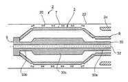
- FIG. 3 aschematically shows, in longitudinal cross-section, a delivery appliance constructed in accordance with the invention in its contracted state for introduction into the body lumen;
- FIG. 3 bis a view corresponding to that of FIG. 3 a but showing the delivery appliance in its expanded state;
- FIG. 3 cis a view corresponding to that of FIG. 3 a but showing the appliance returned to its contracted state for removal from the lumen, while the intravascular device remains anchored within the lumen;
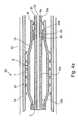
- FIGS. 4 a and 4 bare views corresponding to FIGS. 3 a and 3 b but illustrating another delivery appliance constructed in accordance with the present invention
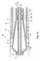
- FIG. 4 cillustrates the delivery appliance of FIGS. 4 a and 4 b after the intravascular device has been deployed and while the outer sleeve is being re-applied over the delivery appliance for removing it from the lumen;
- FIG. 4 dis a view similar to that of FIG. 4 c , but showing the appliance after the outer sleeve has been completely applied;
- FIG. 5schematically shows a transverse cross-section, taken along line V—V of FIG. 4 b , after the delivery appliance has been expanded to deploy the intravascular device at the desired location in the lumen.
- the delivery appliances illustrated in the drawings as preferred embodiments of the inventiondo not utilize expansion balloons, and therefore avoid many of the difficulties briefly described above in the use of such balloons, for delivering intraluminal devices, particularly intravascular devices, into a lumen of a subject's body.
- the delivery methodis substantially the same as in traditional methods, except that the expansion and contraction of the delivery appliance is produced by effecting relative movement between mechanical elements, rather than by the expansion and contraction of a balloon. Accordingly, the description below will concern only the delivery appliance itself and the manner in which it is expanded and contracted when deploying the intravascular device, as the remainder of the deployment procedure would be substantially the same as when using the traditional expansion balloon.
- FIG. 1 aillustrates the external appearance of the expandable part of a delivery appliance constructed in accordance with the present invention in its contracted state
- FIG. 1 billustrates it in its expanded state
- the overall appliancegenerally designated 2 in FIGS. 3 a - 3 c
- Tubular member 3is formed with a plurality of longitudinally-extending, circumferentially-spaced slits 4 terminating along circular lines 5 , 6 at the opposite ends of the tubular member.
- Such a slitted tubethus defines an annular array of stiff supporting strips 7 interconnected together at the opposite ends of the tubular member outwardly of the circular lines 5 and 6 .
- the annular array of supporting strips 7thus define an annular supporting surface for the expandable intraluminal device to be delivered; the end 8 of the tubular member outwardly of circular line 5 defines one end, namely the proximal end, of the annular array of supporting strips; and the opposite end 9 , outwardly of circular line 6 , defines the opposite end, in this case the distal end, of the annular array of supporting strips.
- each of the supporting strips 7 in the annular arrayis laterally deformable to radially expand or radially contract the annular array of supporting strips, and the annular supporting surface defined by them.
- each of the supporting strips 7is stiff in the longitudinal direction but is formed with four integral hinges 11 , 12 , 13 , 14 , which permit the strip to be deformed in the lateral direction, i.e., towards or away from the longitudinal axis LA.
- Integral hinges 11 and 12 at the opposite ends of the annular arrayare aligned with circles 5 and 6 , respectively, defining the proximal and terminal ends of the annular array.
- Integral hinges 13are aligned along a circular line at one end of the annular array, closer to the circular line of integral hinges 11 ; whereas the integral hinges 14 are aligned along another circular line at the opposite end, closer to the circular line of integral hinges 12 .
- FIGS. 2 a and 2 billustrate the construction of each of the supporting strips 7 . It includes a main central section 7 a extending between the two central grooves 13 , 14 ; an end section 7 b defined by groove 11 at one end and joined to the central section 7 a by a juncture section 7 c between the two grooves 11 and 13 ; and an end section 7 d defined by groove 12 at the opposite end joined to the central section 7 a by a juncture section 7 e between the two grooves 12 and 14 .
- FIG. 2 cmore particularly illustrates the construction of integral hinge 14 between the central supporting section 7 a of the supporting strip 7 and the coupling section 7 e coupling it to the distal end section 7 d .
- integral hinge 14is defined by a semi-circular groove extending transversely of the respective supporting strip 7 , permitting the strip to be bent outwardly in the direction of the surface of the supporting strip formed with the groove. That is, when a force is applied to the supporting strip in the axial direction of the supporting strip, groove 14 permits the supporting strip to be deformed more easily in the direction of the surface formed with the groove 14 than in the opposite direction.
- groove 13 at the opposite end of the central supporting section 7 ais also formed on the outer surface of the supporting strip 7 as groove 14 , whereas the two end grooves 11 and 12 are formed on the inner surface of the supporting strip. Accordingly, when an axial force is applied to supporting strip 7 illustrated in FIG. 2 a tending to move the proximal end 7 b towards the distal end 7 d , the supporting strip deforms laterally to the position illustrated in FIG. 2 b , wherein the central section 7 a of the supporting strip moves outwardly.
- the central supporting sections 7 aalways remain parallel to the longitudinal axis LA of the annular array; that is, they define a small-diameter cylindrical supporting surface when in their contracted positions as shown in FIG. 1 a , and a large-diameter cylindrical supporting surface when in their expanded positions as shown in FIG. 1 b.
- FIG. 3 amore particularly illustrates the contracted condition of the delivery appliance 2 , and its annular array 3 of supporting strips 7 , including the expandable intravascular device 20 received on the outer surfaces of the supporting strips 7 so as to be radially expanded by the lateral movements of the supporting strips to their expanded condition shown in FIG. 1 b .
- an intravascular device 20may be, for example, a stent to be deployed in firm engagement with the interior wall of a blood vessel lumen 22 by the expansion of the delivery appliance.
- the delivery appliance 2further includes an outer constraining sleeve 24 which is applied over the intravascular device 20 after the latter has been applied over the outer face of the annular array of supporting strips 7 .
- the outer sleeve 24is of an internal diameter to retain the delivery appliance 2 , after being loaded with the intravascular device 20 , in its contracted condition for movement through the lumen 22 to the desired location where the intravascular device 20 is to be deployed, at which time the outer sleeve 24 is removed for deploying the intravascular device.
- the delivery appliance 2also includes an inner connecting stem 30 extending through the annular array of supporting strips 7 .
- One end 30 a of the connecting stem 30passes through the proximal end 8 of the annular array of supporting strips 7 defined by the end sections 7 b of the supporting strips, and is axially movable with respect that end of the supporting strips.
- the opposite end 30 b of the connecting stem 30is coupled, in any suitable manner as by heat-welding or adhesive, to the end sections 7 d of the annular array of supporting strips 7 defining the distal end of the annular array, so as to be axially movable with such distal end sections of the supporting strips.
- the central section 30 c of connecting stem 30namely that section enclosed by the central supporting sections 7 a of the annular array of supporting strips 7 , is of increased thickness to increase the stiffness of the connecting stem when moved axially in one direction to radially expand the supporting sections 7 a , or in the opposite direction to radially contract the supporting sections.
- Connecting stem 30is hollow, as shown at 30 d , to allow it, and the complete delivery appliance including it, to be received on a guiding wire, shown schematically at 32 .
- a guiding wire 32is introduced into the lumen for guiding the balloon catheter, and the intravascular device carried thereby, to the desired location in the lumen where the intravascular device is to be implanted.
- the same guiding wire 32may thus be used for guiding the delivery appliance 2 of the present invention, and the intravascular device carried thereby, to the desired location in the lumen for implantation therein.
- the illustrated delivery appliancemay be used in the following manner:
- FIG. 3 ashows the annular array 3 of supporting strips 7 in their contracted condition (corresponding to FIG. 1 a ) such that the outer surfaces of the intermediate sections 7 a of the supporting strips 7 define an annular surface of small diameter for receiving the intravascular device 20 in its contracted condition.
- the outer constraining sleeve 24is applied over the intravascular device 20 and thereby retains the delivery appliance 2 in its contracted condition with the intravascular device 20 interposed between the outer sleeve 24 and the outer surfaces of the supporting strips 7 .
- a guiding wire 32is introduced into the lumen and guided to the proper location in accordance with the usual methods used with balloon-type catheters. After the guiding wire 32 has been so introduced, the delivery appliance 2 is applied to the guiding wire, by passing the distal end 30 b of the hollow stem 30 through the proximal end of the guiding wire 32 .
- the guiding wireis then used to guide the movement of the delivery appliance 2 to the desired location for deployment of the intravascular device 20 .
- the proximal end 30 a of the connecting stem 30is extended so as to be of sufficient length so as to be manipulateable externally of the patient's body receiving the intravascular implant.
- the proximal end 8 of the tubular member defining the annular array of supporting strips 7is also extended for manipulation externally of the patient's body.
- the outer constraining sleeve 24is also extended, or is otherwise connected to a device, for external manipulation.
- the outer constraining sleeve 24is removed.
- the proximal end 30 a of the stem 30is then moved (rightwardly, FIG. 3 a ) to apply an axial compressional force to the annular array of supporting strips 7 , and thereby to move the distal end 9 of the annular array of supporting strips 7 towards the proximal end 8 .
- This movement of the opposite ends of the supporting strips 7 towards each otherdeforms the supporting strips 7 laterally in the outward direction, as permitted by the integral hinges 11 - 14 of each of the supporting strips.
- this arrangement of integral hingescauses the intermediate sections 7 a of the supporting strips 7 to move outwardly, while maintaining substantial parallel relationship to the longitudinal axis LA occupied by the guiding wire 32 .
- the intravascular device 20 supported on the outer surfaces of the supporting strips 7is thus expanded into a firm engagement with the walls of the lumen 22 , as shown in FIG. 3 b.
- the proximal end 30 a of the connecting stem 30is moved in the opposite direction (leftwardly, FIGS. 3 a , 3 b ) i.e., to apply an axial extension force to the annular array of supporting strips 7 , and to thereby move the distal end 9 of the annular array 3 of supporting strips 7 away from the proximal end 8 .
- Thiscauses the supporting strips 7 to be deformed laterally inwardly towards the longitudinal axis LA of the delivery appliance, i.e., radially contracting the diameter defined by the outer surfaces of the supporting strips.
- the tubular member defining the supporting strips 7may be made of any suitable elastic material, such as plastic, metal, or a combination of plastic and metal, providing stiffness in the longitudinal direction, but permitting deformation in the lateral direction by the integral hinges 11 - 14 formed in the strips as described above.
- the expandable intravascular device 24may be of any known type and constructed of known materials, such as described, for example, in International Patent Application PCT/IL01/00624 by the same Applicant, the contents of which are incorporated herein by reference.
- FIGS. 4 a - 4 dillustrate another embodiment of the invention wherein the delivery appliance, therein generally designated 40 , is moved by means of a spring to its expanded condition for deploying the intravascular device after the delivery appliance has been moved to the proper location and the constraining outer sleeve removed.
- the proximal end 8 of the tubular member defining the annular array of supporting strips 7need not be extended for manipulation externally of the patient's body.
- the delivery appliance 40 illustrated in FIGS. 4 a - 4 dis generally of the same construction as delivery appliance 2 illustrated in FIGS. 1 a - 3 c , and therefore, for the sake of brevity, the same reference numerals have been used for identifying corresponding parts.
- the proximal end 8 ′ of the tubular member defining the annular supporting strips 7is not extended so as to be externally of the patient's body as briefly described above, but rather is formed with an annular rib 8 a on its inner surface at the proximal end of the tubular member, and with a second annular rib 8 b on its inner surface inwardly of annular rib 8 a .
- the two ribs 8 a , 8 bthus define axially-spaced annular shoulders on the inner face of proximal end 8 of the tubular member.
- the proximal end 30 a of the inner stem 30is formed on its outer surface with an annular rib 30 d defining an annular shoulder between the two annular shoulders 8 a , 8 b .
- a compression spring 42is interposed between annular shoulder 30 d and annular shoulder 8 b at the proximal end 8 ′ of the tubular member.
- the delivery appliance 40 in this conditionis delivered through the patient's lumen to the implantation site, whereupon the constraining sleeve 24 is removed, as described above.
- spring 42expands and automatically moves the proximal end 30 a of stem 30 outwardly of the proximal end 8 ′ of the supporting strips 7 , thereby moving the opposite end 8 ′, 9 of the annular array of supporting strips 7 towards each other.
- This movementaxially compresses the supporting strips 7 and thereby deforms them laterally outwardly in the same manner as described above with respect to FIGS. 3 a - 3 , to deploy the intravascular device 20 against the inner wall of the lumen 22 as shown in FIG. 4 b.
- FIG. 4 cillustrates the re-application of the constraining sleeve 24 to the outer surfaces of the supporting strips 7 in order to laterally deform them inwardly towards the longitudinal axis of the delivery appliance; and
- FIG. 4 dillustrates the condition of the delivery appliance 40 after the constraining has been fully applied, to thereby permit removal of the delivery appliance 40 from the lumen 22 .
- FIG. 5illustrates the cross-section of the delivery appliance 40 of FIGS. 4 a - 4 d , (as well as that of appliance 2 of FIGS. 1 a - 3 c ) in the expanded condition of the delivery appliance, at the time the annular array of supporting strips is radially expanded to press the intravascular device 20 firmly against the inner wall of the lumen 22 .
- a flow passagewayis maintained through the delivery device so as to avoid the hazards of balloon-type delivery devices blocking the flow of the blood.
- the described arrangement of integral hinges formed in each of the supporting strips 7causes the supporting strips to move outwardly, parallel to the longitudinal axis of the delivery appliance, thereby maintaining the flow passageway through the delivery appliance. It also better assures a firm engagement of the intravascular device against the inner wall of the lumen even when used in relatively large-size lumens.
- the intraluminal devicecould be of the self-expansible-type such that it self automatically expands upon the removal of the outer constricting sleeve, or could be of the type which is expanded by the axial compressional force applied to the opposite ends of the tubular member defining the annular array of supporting strips 7 .
- the annular array of supporting strips 7could be constructed of individual strips joined together at their proximal and distal ends, or could be provided with a different construction of integral hinges.
- integral hingescould be used so as to define a plurality of discrete axially-spaced annular supporting surfaces, rather than a single continuous annular supporting surface, particularly where the intraluminal device to be applied is relatively long.
- the inventioncould be used in other medical applications, for delivering other types of expandable devices to desired locations in lumens, and could also be used in non-medical applications for the application of devices to lumens or other tubular passageways.
Landscapes
- Health & Medical Sciences (AREA)
- Engineering & Computer Science (AREA)
- Biomedical Technology (AREA)
- Heart & Thoracic Surgery (AREA)
- Oral & Maxillofacial Surgery (AREA)
- Transplantation (AREA)
- Cardiology (AREA)
- Vascular Medicine (AREA)
- Life Sciences & Earth Sciences (AREA)
- Animal Behavior & Ethology (AREA)
- General Health & Medical Sciences (AREA)
- Public Health (AREA)
- Veterinary Medicine (AREA)
- Media Introduction/Drainage Providing Device (AREA)
- Surgical Instruments (AREA)
Abstract
Description
Claims (25)
Priority Applications (1)
| Application Number | Priority Date | Filing Date | Title |
|---|---|---|---|
| US10/288,472US6740105B2 (en) | 2001-11-23 | 2002-11-06 | Expandable delivery appliance particularly for delivering intravascular devices |
Applications Claiming Priority (2)
| Application Number | Priority Date | Filing Date | Title |
|---|---|---|---|
| US33205701P | 2001-11-23 | 2001-11-23 | |
| US10/288,472US6740105B2 (en) | 2001-11-23 | 2002-11-06 | Expandable delivery appliance particularly for delivering intravascular devices |
Publications (2)
| Publication Number | Publication Date |
|---|---|
| US20030100939A1 US20030100939A1 (en) | 2003-05-29 |
| US6740105B2true US6740105B2 (en) | 2004-05-25 |
Family
ID=23296539
Family Applications (1)
| Application Number | Title | Priority Date | Filing Date |
|---|---|---|---|
| US10/288,472Expired - Fee RelatedUS6740105B2 (en) | 2001-11-23 | 2002-11-06 | Expandable delivery appliance particularly for delivering intravascular devices |
Country Status (3)
| Country | Link |
|---|---|
| US (1) | US6740105B2 (en) |
| AU (1) | AU2002347579A1 (en) |
| WO (1) | WO2003043676A2 (en) |
Cited By (60)
| Publication number | Priority date | Publication date | Assignee | Title |
|---|---|---|---|---|
| US20100210899A1 (en)* | 2009-01-21 | 2010-08-19 | Tendyne Medical, Inc. | Method for percutaneous lateral access to the left ventricle for treatment of mitral insufficiency by papillary muscle alignment |
| US20110004296A1 (en)* | 2007-09-13 | 2011-01-06 | Georg Lutter | Heart Valve Stent |
| US20110015476A1 (en)* | 2009-03-04 | 2011-01-20 | Jeff Franco | Devices and Methods for Treating Cardiomyopathy |
| US20110093060A1 (en)* | 2009-07-02 | 2011-04-21 | Cartledge Richard G | Surgical Implant Devices and Methods for their Manufacture and Use |
| US8147534B2 (en) | 2005-05-25 | 2012-04-03 | Tyco Healthcare Group Lp | System and method for delivering and deploying an occluding device within a vessel |
| US8267985B2 (en) | 2005-05-25 | 2012-09-18 | Tyco Healthcare Group Lp | System and method for delivering and deploying an occluding device within a vessel |
| US8273101B2 (en) | 2005-05-25 | 2012-09-25 | Tyco Healthcare Group Lp | System and method for delivering and deploying an occluding device within a vessel |
| US8382825B2 (en) | 2004-05-25 | 2013-02-26 | Covidien Lp | Flexible vascular occluding device |
| US8394119B2 (en) | 2006-02-22 | 2013-03-12 | Covidien Lp | Stents having radiopaque mesh |
| US8398701B2 (en) | 2004-05-25 | 2013-03-19 | Covidien Lp | Flexible vascular occluding device |
| US8617234B2 (en) | 2004-05-25 | 2013-12-31 | Covidien Lp | Flexible vascular occluding device |
| US8623067B2 (en) | 2004-05-25 | 2014-01-07 | Covidien Lp | Methods and apparatus for luminal stenting |
| US9114001B2 (en) | 2012-10-30 | 2015-08-25 | Covidien Lp | Systems for attaining a predetermined porosity of a vascular device |
| US9138335B2 (en) | 2006-07-31 | 2015-09-22 | Syntheon Cardiology, Llc | Surgical implant devices and methods for their manufacture and use |
| US9157174B2 (en) | 2013-02-05 | 2015-10-13 | Covidien Lp | Vascular device for aneurysm treatment and providing blood flow into a perforator vessel |
| US9155647B2 (en) | 2012-07-18 | 2015-10-13 | Covidien Lp | Methods and apparatus for luminal stenting |
| US20160022464A1 (en)* | 2001-08-27 | 2016-01-28 | Boston Scientific Scimed, Inc. | Positioning tools and methods for implanting medical devices |
| US9452070B2 (en) | 2012-10-31 | 2016-09-27 | Covidien Lp | Methods and systems for increasing a density of a region of a vascular device |
| US9480559B2 (en) | 2011-08-11 | 2016-11-01 | Tendyne Holdings, Inc. | Prosthetic valves and related inventions |
| US9486306B2 (en) | 2013-04-02 | 2016-11-08 | Tendyne Holdings, Inc. | Inflatable annular sealing device for prosthetic mitral valve |
| US9526611B2 (en) | 2013-10-29 | 2016-12-27 | Tendyne Holdings, Inc. | Apparatus and methods for delivery of transcatheter prosthetic valves |
| US9566178B2 (en) | 2010-06-24 | 2017-02-14 | Edwards Lifesciences Cardiaq Llc | Actively controllable stent, stent graft, heart valve and method of controlling same |
| US9585743B2 (en) | 2006-07-31 | 2017-03-07 | Edwards Lifesciences Cardiaq Llc | Surgical implant devices and methods for their manufacture and use |
| US9597181B2 (en) | 2013-06-25 | 2017-03-21 | Tendyne Holdings, Inc. | Thrombus management and structural compliance features for prosthetic heart valves |
| US9610159B2 (en) | 2013-05-30 | 2017-04-04 | Tendyne Holdings, Inc. | Structural members for prosthetic mitral valves |
| US9675454B2 (en) | 2012-07-30 | 2017-06-13 | Tendyne Holdings, Inc. | Delivery systems and methods for transcatheter prosthetic valves |
| US9675482B2 (en) | 2008-05-13 | 2017-06-13 | Covidien Lp | Braid implant delivery systems |
| US9814611B2 (en) | 2007-07-31 | 2017-11-14 | Edwards Lifesciences Cardiaq Llc | Actively controllable stent, stent graft, heart valve and method of controlling same |
| US9827093B2 (en) | 2011-10-21 | 2017-11-28 | Edwards Lifesciences Cardiaq Llc | Actively controllable stent, stent graft, heart valve and method of controlling same |
| US9827092B2 (en) | 2011-12-16 | 2017-11-28 | Tendyne Holdings, Inc. | Tethers for prosthetic mitral valve |
| US9895221B2 (en) | 2012-07-28 | 2018-02-20 | Tendyne Holdings, Inc. | Multi-component designs for heart valve retrieval device, sealing structures and stent assembly |
| US9943427B2 (en) | 2012-11-06 | 2018-04-17 | Covidien Lp | Shaped occluding devices and methods of using the same |
| US9986993B2 (en) | 2014-02-11 | 2018-06-05 | Tendyne Holdings, Inc. | Adjustable tether and epicardial pad system for prosthetic heart valve |
| US10004618B2 (en) | 2004-05-25 | 2018-06-26 | Covidien Lp | Methods and apparatus for luminal stenting |
| US10201419B2 (en) | 2014-02-05 | 2019-02-12 | Tendyne Holdings, Inc. | Apparatus and methods for transfemoral delivery of prosthetic mitral valve |
| US10327894B2 (en) | 2015-09-18 | 2019-06-25 | Tendyne Holdings, Inc. | Methods for delivery of prosthetic mitral valves |
| US10463489B2 (en) | 2013-04-02 | 2019-11-05 | Tendyne Holdings, Inc. | Prosthetic heart valve and systems and methods for delivering the same |
| US10463494B2 (en) | 2013-04-02 | 2019-11-05 | Tendyne Holdings, Inc. | Prosthetic heart valve and systems and methods for delivering the same |
| US10470877B2 (en) | 2016-05-03 | 2019-11-12 | Tendyne Holdings, Inc. | Apparatus and methods for anterior valve leaflet management |
| US10478293B2 (en) | 2013-04-04 | 2019-11-19 | Tendyne Holdings, Inc. | Retrieval and repositioning system for prosthetic heart valve |
| US10517728B2 (en) | 2014-03-10 | 2019-12-31 | Tendyne Holdings, Inc. | Devices and methods for positioning and monitoring tether load for prosthetic mitral valve |
| US10555718B2 (en) | 2013-10-17 | 2020-02-11 | Tendyne Holdings, Inc. | Apparatus and methods for alignment and deployment of intracardiac devices |
| US10610358B2 (en) | 2015-12-28 | 2020-04-07 | Tendyne Holdings, Inc. | Atrial pocket closures for prosthetic heart valves |
| US10610354B2 (en) | 2013-08-01 | 2020-04-07 | Tendyne Holdings, Inc. | Epicardial anchor devices and methods |
| US10610356B2 (en) | 2015-02-05 | 2020-04-07 | Tendyne Holdings, Inc. | Expandable epicardial pads and devices and methods for delivery of same |
| US10667905B2 (en) | 2015-04-16 | 2020-06-02 | Tendyne Holdings, Inc. | Apparatus and methods for delivery, repositioning, and retrieval of transcatheter prosthetic valves |
| US10786351B2 (en) | 2015-01-07 | 2020-09-29 | Tendyne Holdings, Inc. | Prosthetic mitral valves and apparatus and methods for delivery of same |
| US11039921B2 (en) | 2016-06-13 | 2021-06-22 | Tendyne Holdings, Inc. | Sequential delivery of two-part prosthetic mitral valve |
| US11065116B2 (en) | 2016-07-12 | 2021-07-20 | Tendyne Holdings, Inc. | Apparatus and methods for trans-septal retrieval of prosthetic heart valves |
| US11090157B2 (en) | 2016-06-30 | 2021-08-17 | Tendyne Holdings, Inc. | Prosthetic heart valves and apparatus and methods for delivery of same |
| US11096782B2 (en) | 2015-12-03 | 2021-08-24 | Tendyne Holdings, Inc. | Frame features for prosthetic mitral valves |
| US11154399B2 (en) | 2017-07-13 | 2021-10-26 | Tendyne Holdings, Inc. | Prosthetic heart valves and apparatus and methods for delivery of same |
| US11179236B2 (en) | 2009-12-08 | 2021-11-23 | Colorado State University Research Foundation | Device and system for transcatheter mitral valve replacement |
| US11191639B2 (en) | 2017-08-28 | 2021-12-07 | Tendyne Holdings, Inc. | Prosthetic heart valves with tether coupling features |
| US11224510B2 (en) | 2013-04-02 | 2022-01-18 | Tendyne Holdings, Inc. | Prosthetic heart valve and systems and methods for delivering the same |
| US11648110B2 (en) | 2019-12-05 | 2023-05-16 | Tendyne Holdings, Inc. | Braided anchor for mitral valve |
| US11648114B2 (en) | 2019-12-20 | 2023-05-16 | Tendyne Holdings, Inc. | Distally loaded sheath and loading funnel |
| US11678980B2 (en) | 2020-08-19 | 2023-06-20 | Tendyne Holdings, Inc. | Fully-transseptal apical pad with pulley for tensioning |
| US11951002B2 (en) | 2020-03-30 | 2024-04-09 | Tendyne Holdings, Inc. | Apparatus and methods for valve and tether fixation |
| US12419764B2 (en) | 2018-03-12 | 2025-09-23 | Fluid Biomed Inc. | Bioabsorbable flow diverting scaffold |
Families Citing this family (140)
| Publication number | Priority date | Publication date | Assignee | Title |
|---|---|---|---|---|
| DK124690D0 (en) | 1990-05-18 | 1990-05-18 | Henning Rud Andersen | FAT PROTECTION FOR IMPLEMENTATION IN THE BODY FOR REPLACEMENT OF NATURAL FLEET AND CATS FOR USE IN IMPLEMENTING A SUCH FAT PROTECTION |
| EP0850607A1 (en) | 1996-12-31 | 1998-07-01 | Cordis Corporation | Valve prosthesis for implantation in body channels |
| US6454799B1 (en) | 2000-04-06 | 2002-09-24 | Edwards Lifesciences Corporation | Minimally-invasive heart valves and methods of use |
| US7556646B2 (en) | 2001-09-13 | 2009-07-07 | Edwards Lifesciences Corporation | Methods and apparatuses for deploying minimally-invasive heart valves |
| US6733525B2 (en) | 2001-03-23 | 2004-05-11 | Edwards Lifesciences Corporation | Rolled minimally-invasive heart valves and methods of use |
| US8771302B2 (en) | 2001-06-29 | 2014-07-08 | Medtronic, Inc. | Method and apparatus for resecting and replacing an aortic valve |
| US7544206B2 (en) | 2001-06-29 | 2009-06-09 | Medtronic, Inc. | Method and apparatus for resecting and replacing an aortic valve |
| US8623077B2 (en) | 2001-06-29 | 2014-01-07 | Medtronic, Inc. | Apparatus for replacing a cardiac valve |
| US20030100945A1 (en) | 2001-11-23 | 2003-05-29 | Mindguard Ltd. | Implantable intraluminal device and method of using same in treating aneurysms |
| US6893460B2 (en) | 2001-10-11 | 2005-05-17 | Percutaneous Valve Technologies Inc. | Implantable prosthetic valve |
| US7399315B2 (en) | 2003-03-18 | 2008-07-15 | Edwards Lifescience Corporation | Minimally-invasive heart valve with cusp positioners |
| US20050075725A1 (en) | 2003-10-02 | 2005-04-07 | Rowe Stanton J. | Implantable prosthetic valve with non-laminar flow |
| AU2004324043A1 (en) | 2004-10-02 | 2006-04-20 | Christoph Hans Huber | Methods and devices for repair or replacement of heart valves or adjacent tissue without the need for full cardiopulmonary support |
| US7780723B2 (en) | 2005-06-13 | 2010-08-24 | Edwards Lifesciences Corporation | Heart valve delivery system |
| US8236045B2 (en) | 2006-12-22 | 2012-08-07 | Edwards Lifesciences Corporation | Implantable prosthetic valve assembly and method of making the same |
| US8100820B2 (en)* | 2007-08-22 | 2012-01-24 | Edwards Lifesciences Corporation | Implantable device for treatment of ventricular dilation |
| EP3443938B1 (en) | 2007-09-26 | 2024-01-24 | St. Jude Medical, LLC | Collapsible prosthetic heart valves |
| US9532868B2 (en) | 2007-09-28 | 2017-01-03 | St. Jude Medical, Inc. | Collapsible-expandable prosthetic heart valves with structures for clamping native tissue |
| ES2781686T3 (en) | 2007-12-14 | 2020-09-04 | Edwards Lifesciences Corp | Leaflet Junction Frame for a Prosthetic Valve |
| EP3912597A1 (en)* | 2008-02-29 | 2021-11-24 | Edwards Lifesciences Corporation | Expandable member for deploying a prosthetic device |
| US9241792B2 (en) | 2008-02-29 | 2016-01-26 | Edwards Lifesciences Corporation | Two-step heart valve implantation |
| US20090276040A1 (en) | 2008-05-01 | 2009-11-05 | Edwards Lifesciences Corporation | Device and method for replacing mitral valve |
| US9061119B2 (en)* | 2008-05-09 | 2015-06-23 | Edwards Lifesciences Corporation | Low profile delivery system for transcatheter heart valve |
| PL4223257T3 (en) | 2008-06-06 | 2024-09-23 | Edwards Lifesciences Corporation | LOW-PROFILE TRANSCATHETIC HEART VALVE |
| US8323335B2 (en) | 2008-06-20 | 2012-12-04 | Edwards Lifesciences Corporation | Retaining mechanisms for prosthetic valves and methods for using |
| EP2815724B2 (en) | 2008-07-15 | 2024-03-13 | St. Jude Medical, Inc. | Collapsible and re-expandable prosthetic heart valve cuff designs and complementary technological applications |
| US8652202B2 (en)* | 2008-08-22 | 2014-02-18 | Edwards Lifesciences Corporation | Prosthetic heart valve and delivery apparatus |
| US8790387B2 (en) | 2008-10-10 | 2014-07-29 | Edwards Lifesciences Corporation | Expandable sheath for introducing an endovascular delivery device into a body |
| US8690936B2 (en) | 2008-10-10 | 2014-04-08 | Edwards Lifesciences Corporation | Expandable sheath for introducing an endovascular delivery device into a body |
| US20100217382A1 (en)* | 2009-02-25 | 2010-08-26 | Edwards Lifesciences | Mitral valve replacement with atrial anchoring |
| CA2961053C (en) | 2009-04-15 | 2019-04-30 | Edwards Lifesciences Cardiaq Llc | Vascular implant and delivery system |
| NZ596179A (en) | 2009-04-29 | 2014-05-30 | Cleveland Clinic Foundation | Apparatus and method for replacing a diseased cardiac valve |
| US8439970B2 (en) | 2009-07-14 | 2013-05-14 | Edwards Lifesciences Corporation | Transapical delivery system for heart valves |
| US8652203B2 (en) | 2010-09-23 | 2014-02-18 | Cardiaq Valve Technologies, Inc. | Replacement heart valves, delivery devices and methods |
| US8449599B2 (en) | 2009-12-04 | 2013-05-28 | Edwards Lifesciences Corporation | Prosthetic valve for replacing mitral valve |
| US8795354B2 (en)* | 2010-03-05 | 2014-08-05 | Edwards Lifesciences Corporation | Low-profile heart valve and delivery system |
| AU2011275468B2 (en) | 2010-07-09 | 2014-02-06 | Highlife Sas | Transcatheter atrio-ventricular valve prosthesis |
| US9326853B2 (en) | 2010-07-23 | 2016-05-03 | Edwards Lifesciences Corporation | Retaining mechanisms for prosthetic valves |
| US8568475B2 (en) | 2010-10-05 | 2013-10-29 | Edwards Lifesciences Corporation | Spiraled commissure attachment for prosthetic valve |
| DK4233795T3 (en) | 2010-10-05 | 2024-08-26 | Edwards Lifesciences Corp | Prosthetic heart valve |
| US9895517B2 (en) | 2011-01-18 | 2018-02-20 | Loma Vista Medical, Inc. | Inflatable medical devices |
| US9155619B2 (en) | 2011-02-25 | 2015-10-13 | Edwards Lifesciences Corporation | Prosthetic heart valve delivery apparatus |
| CN103561686B (en)* | 2011-03-03 | 2016-03-30 | 英派尔科技开发有限公司 | Temporary perfusion channel for percutaneous delivery of expandable balloon stents |
| US9289282B2 (en) | 2011-05-31 | 2016-03-22 | Edwards Lifesciences Corporation | System and method for treating valve insufficiency or vessel dilatation |
| US8795357B2 (en) | 2011-07-15 | 2014-08-05 | Edwards Lifesciences Corporation | Perivalvular sealing for transcatheter heart valve |
| US9119716B2 (en) | 2011-07-27 | 2015-09-01 | Edwards Lifesciences Corporation | Delivery systems for prosthetic heart valve |
| US12364596B2 (en) | 2011-10-21 | 2025-07-22 | Edwards Lifesciences Cardiaq Llc | Actively controllable stent, stent graft, heart valve and method of controlling same |
| CN104114127B (en) | 2011-12-09 | 2017-09-05 | 爱德华兹生命科学公司 | Prosthetic heart valve with improved commissural support |
| US8652145B2 (en) | 2011-12-14 | 2014-02-18 | Edwards Lifesciences Corporation | System and method for crimping a prosthetic valve |
| EP3424469A1 (en) | 2012-02-22 | 2019-01-09 | Syntheon TAVR, LLC | Actively controllable stent, stent graft and heart valve |
| EP2854700B1 (en) | 2012-05-31 | 2021-07-07 | Javelin Medical Ltd. | Devices for embolic protection |
| WO2014111911A1 (en)* | 2013-01-18 | 2014-07-24 | Javelin Medical Ltd. | Monofilament implants and systems for delivery thereof |
| US9510946B2 (en) | 2012-09-06 | 2016-12-06 | Edwards Lifesciences Corporation | Heart valve sealing devices |
| US10799348B2 (en) | 2012-10-18 | 2020-10-13 | Loma Vista Medical, Inc. | Reinforced inflatable medical devices |
| EP4162902A1 (en) | 2012-11-21 | 2023-04-12 | Edwards Lifesciences Corporation | Retaining mechanisms for prosthetic heart valves |
| US9439763B2 (en) | 2013-02-04 | 2016-09-13 | Edwards Lifesciences Corporation | Prosthetic valve for replacing mitral valve |
| US9168129B2 (en) | 2013-02-12 | 2015-10-27 | Edwards Lifesciences Corporation | Artificial heart valve with scalloped frame design |
| US20140277427A1 (en) | 2013-03-14 | 2014-09-18 | Cardiaq Valve Technologies, Inc. | Prosthesis for atraumatically grasping intralumenal tissue and methods of delivery |
| EP2999436B1 (en) | 2013-05-20 | 2018-08-29 | Edwards Lifesciences Corporation | Prosthetic heart valve delivery apparatus |
| CA3199859A1 (en) | 2013-08-12 | 2015-02-19 | Mitral Valve Technologies Sarl | Apparatus and methods for implanting a replacement heart valve |
| LT3545906T (en) | 2013-08-14 | 2021-03-10 | Mitral Valve Technologies Sarl | Replacement heart valve apparatus |
| US9913715B2 (en) | 2013-11-06 | 2018-03-13 | St. Jude Medical, Cardiology Division, Inc. | Paravalvular leak sealing mechanism |
| CR20160240A (en) | 2013-11-11 | 2016-08-04 | Edwards Lifesciences Cardiaq Llc | SYSTEMS AND METHODS FOR THE MANUFACTURE OF THE FRAME OF A CANNULA |
| US9622863B2 (en) | 2013-11-22 | 2017-04-18 | Edwards Lifesciences Corporation | Aortic insufficiency repair device and method |
| US10098734B2 (en) | 2013-12-05 | 2018-10-16 | Edwards Lifesciences Corporation | Prosthetic heart valve and delivery apparatus |
| US9592110B1 (en) | 2013-12-06 | 2017-03-14 | Javelin Medical, Ltd. | Systems and methods for implant delivery |
| US9901444B2 (en) | 2013-12-17 | 2018-02-27 | Edwards Lifesciences Corporation | Inverted valve structure |
| PL4062874T4 (en) | 2014-02-18 | 2024-03-04 | Edwards Lifesciences Corporation | Flexible commissure frame |
| SG11201606836TA (en) | 2014-02-20 | 2016-09-29 | Mitral Valve Technologies Sarl | Coiled anchor for supporting prosthetic heart valve, prosthetic heart valve, and deployment device |
| EP3782585B1 (en) | 2014-02-21 | 2023-06-28 | Mitral Valve Technologies Sàrl | Prosthetic mitral valve and anchoring device |
| US10195025B2 (en) | 2014-05-12 | 2019-02-05 | Edwards Lifesciences Corporation | Prosthetic heart valve |
| US9532870B2 (en) | 2014-06-06 | 2017-01-03 | Edwards Lifesciences Corporation | Prosthetic valve for replacing a mitral valve |
| US10195026B2 (en) | 2014-07-22 | 2019-02-05 | Edwards Lifesciences Corporation | Mitral valve anchoring |
| US10058424B2 (en) | 2014-08-21 | 2018-08-28 | Edwards Lifesciences Corporation | Dual-flange prosthetic valve frame |
| US10016272B2 (en) | 2014-09-12 | 2018-07-10 | Mitral Valve Technologies Sarl | Mitral repair and replacement devices and methods |
| KR20170066470A (en) | 2014-09-28 | 2017-06-14 | 카디오키네틱스 인크. | Apparatuses for treating cardiac dysfunction |
| US10531951B2 (en) | 2014-11-26 | 2020-01-14 | Edwards Lifesciences Corporation | Transcatheter prosthetic heart valve and delivery system |
| US10231834B2 (en) | 2015-02-09 | 2019-03-19 | Edwards Lifesciences Corporation | Low profile transseptal catheter and implant system for minimally invasive valve procedure |
| US10039637B2 (en) | 2015-02-11 | 2018-08-07 | Edwards Lifesciences Corporation | Heart valve docking devices and implanting methods |
| WO2016153918A1 (en) | 2015-03-20 | 2016-09-29 | Cardiokinetix, Inc. | Systems and methods for delivering an implantable device |
| US10327896B2 (en) | 2015-04-10 | 2019-06-25 | Edwards Lifesciences Corporation | Expandable sheath with elastomeric cross sectional portions |
| US10792471B2 (en) | 2015-04-10 | 2020-10-06 | Edwards Lifesciences Corporation | Expandable sheath |
| US12194256B2 (en) | 2015-04-10 | 2025-01-14 | Edwards Lifesciences Corporation | Expandable sheath |
| US10010417B2 (en) | 2015-04-16 | 2018-07-03 | Edwards Lifesciences Corporation | Low-profile prosthetic heart valve for replacing a mitral valve |
| US10064718B2 (en) | 2015-04-16 | 2018-09-04 | Edwards Lifesciences Corporation | Low-profile prosthetic heart valve for replacing a mitral valve |
| US10232564B2 (en) | 2015-04-29 | 2019-03-19 | Edwards Lifesciences Corporation | Laminated sealing member for prosthetic heart valve |
| US9974650B2 (en) | 2015-07-14 | 2018-05-22 | Edwards Lifesciences Corporation | Prosthetic heart valve |
| US10314703B2 (en) | 2015-09-21 | 2019-06-11 | Edwards Lifesciences Corporation | Cylindrical implant and balloon |
| US10376364B2 (en) | 2015-11-10 | 2019-08-13 | Edwards Lifesciences Corporation | Implant delivery capsule |
| US10470876B2 (en) | 2015-11-10 | 2019-11-12 | Edwards Lifesciences Corporation | Transcatheter heart valve for replacing natural mitral valve |
| US10179043B2 (en) | 2016-02-12 | 2019-01-15 | Edwards Lifesciences Corporation | Prosthetic heart valve having multi-level sealing member |
| US10779941B2 (en)* | 2016-03-08 | 2020-09-22 | Edwards Lifesciences Corporation | Delivery cylinder for prosthetic implant |
| CN108882980B (en) | 2016-03-24 | 2020-12-08 | 爱德华兹生命科学公司 | Delivery system for prosthetic heart valve |
| US11096781B2 (en) | 2016-08-01 | 2021-08-24 | Edwards Lifesciences Corporation | Prosthetic heart valve |
| US10575944B2 (en) | 2016-09-22 | 2020-03-03 | Edwards Lifesciences Corporation | Prosthetic heart valve with reduced stitching |
| EP4331536A3 (en) | 2016-10-21 | 2024-05-22 | Javelin Medical Ltd. | Systems, methods and devices for embolic protection |
| US10758348B2 (en) | 2016-11-02 | 2020-09-01 | Edwards Lifesciences Corporation | Supra and sub-annular mitral valve delivery system |
| US10463484B2 (en) | 2016-11-17 | 2019-11-05 | Edwards Lifesciences Corporation | Prosthetic heart valve having leaflet inflow below frame |
| US10973631B2 (en) | 2016-11-17 | 2021-04-13 | Edwards Lifesciences Corporation | Crimping accessory device for a prosthetic valve |
| US10603165B2 (en) | 2016-12-06 | 2020-03-31 | Edwards Lifesciences Corporation | Mechanically expanding heart valve and delivery apparatus therefor |
| US11185406B2 (en) | 2017-01-23 | 2021-11-30 | Edwards Lifesciences Corporation | Covered prosthetic heart valve |
| US11013600B2 (en) | 2017-01-23 | 2021-05-25 | Edwards Lifesciences Corporation | Covered prosthetic heart valve |
| US11654023B2 (en) | 2017-01-23 | 2023-05-23 | Edwards Lifesciences Corporation | Covered prosthetic heart valve |
| US11135056B2 (en) | 2017-05-15 | 2021-10-05 | Edwards Lifesciences Corporation | Devices and methods of commissure formation for prosthetic heart valve |
| CN114631913A (en) | 2017-05-22 | 2022-06-17 | 爱德华兹生命科学公司 | Valve anchor and installation method |
| US12064341B2 (en) | 2017-05-31 | 2024-08-20 | Edwards Lifesciences Corporation | Sealing member for prosthetic heart valve |
| US11026785B2 (en) | 2017-06-05 | 2021-06-08 | Edwards Lifesciences Corporation | Mechanically expandable heart valve |
| US10869759B2 (en) | 2017-06-05 | 2020-12-22 | Edwards Lifesciences Corporation | Mechanically expandable heart valve |
| US10918473B2 (en) | 2017-07-18 | 2021-02-16 | Edwards Lifesciences Corporation | Transcatheter heart valve storage container and crimping mechanism |
| WO2019032992A2 (en) | 2017-08-11 | 2019-02-14 | Edwards Lifesciences Corportion | Sealing element for prosthetic heart valve |
| US11083575B2 (en) | 2017-08-14 | 2021-08-10 | Edwards Lifesciences Corporation | Heart valve frame design with non-uniform struts |
| US10932903B2 (en) | 2017-08-15 | 2021-03-02 | Edwards Lifesciences Corporation | Skirt assembly for implantable prosthetic valve |
| US10898319B2 (en) | 2017-08-17 | 2021-01-26 | Edwards Lifesciences Corporation | Sealing member for prosthetic heart valve |
| US10973628B2 (en) | 2017-08-18 | 2021-04-13 | Edwards Lifesciences Corporation | Pericardial sealing member for prosthetic heart valve |
| US10722353B2 (en) | 2017-08-21 | 2020-07-28 | Edwards Lifesciences Corporation | Sealing member for prosthetic heart valve |
| US10973629B2 (en) | 2017-09-06 | 2021-04-13 | Edwards Lifesciences Corporation | Sealing member for prosthetic heart valve |
| US11147667B2 (en) | 2017-09-08 | 2021-10-19 | Edwards Lifesciences Corporation | Sealing member for prosthetic heart valve |
| US11318011B2 (en) | 2018-04-27 | 2022-05-03 | Edwards Lifesciences Corporation | Mechanically expandable heart valve with leaflet clamps |
| US12161551B2 (en) | 2018-08-30 | 2024-12-10 | Edwards Lifesciences Corporation | Systems and methods for sizing and implanting prosthetic heart valves |
| US12310847B2 (en) | 2018-10-19 | 2025-05-27 | Edwards Lifesciences Corporation | Prosthetic heart valve having non-cylindrical frame |
| KR20210082188A (en) | 2018-10-19 | 2021-07-02 | 에드워즈 라이프사이언시스 코포레이션 | Artificial heart valve with non-cylindrical frame |
| JP7395598B2 (en) | 2018-10-30 | 2023-12-11 | エドワーズ ライフサイエンシーズ コーポレイション | Monitoring valve diameter and force of prosthetic valves |
| WO2020117887A1 (en) | 2018-12-06 | 2020-06-11 | Edwards Lifesciences Corporation | Mechanically expandable prosthetic heart valve and delivery apparatus |
| WO2020150378A1 (en) | 2019-01-17 | 2020-07-23 | Edwards Lifesciences Corporation | Frame for prosthetic heart valve |
| CN119857008A (en) | 2019-01-28 | 2025-04-22 | 爱德华兹生命科学公司 | Prosthetic valve |
| WO2020167531A1 (en) | 2019-02-13 | 2020-08-20 | Edwards Lifesciences Corporation | Heart valve frame design with non-uniform struts |
| JP7541023B2 (en) | 2019-03-04 | 2024-08-27 | エドワーズ ライフサイエンシーズ コーポレイション | Commissure attachment for artificial valves |
| JP7520034B2 (en) | 2019-03-26 | 2024-07-22 | エドワーズ ライフサイエンシーズ コーポレイション | Artificial Heart Valves |
| EP4467102A1 (en) | 2019-04-11 | 2024-11-27 | Edwards Lifesciences Corporation | Method of assembling a prosthetic heart valve |
| ES2982566T3 (en) | 2019-04-23 | 2024-10-16 | Edwards Lifesciences Corp | Motorized implant delivery system |
| EP3999000A1 (en) | 2019-07-19 | 2022-05-25 | Edwards Lifesciences Corporation | Crimping devices for prosthetic heart valves |
| EP4061283B1 (en) | 2020-01-10 | 2024-12-04 | Edwards Lifesciences Corporation | Assembly methods for a prosthetic heart valve leaflet |
| CN115426980A (en) | 2020-03-03 | 2022-12-02 | 爱德华兹生命科学公司 | Prosthetic heart valve leaflet commissure assemblies and methods |
| EP4167911B1 (en) | 2020-06-18 | 2024-10-30 | Edwards Lifesciences Corporation | Crimping methods |
| EP4243734A1 (en) | 2020-11-12 | 2023-09-20 | Edwards Lifesciences Corporation | Prosthetic heart valve leaflet assemblies and methods |
| EP4247297A1 (en) | 2020-12-18 | 2023-09-27 | Edwards Lifesciences Corporation | Storage jar assembly for aprosthetic heart valve |
| EP4281014A1 (en) | 2021-01-20 | 2023-11-29 | Edwards Lifesciences Corporation | Connecting skirt for attaching a leaflet to a frame of a prosthetic heart valve |
| KR20230160297A (en) | 2021-03-23 | 2023-11-23 | 에드워즈 라이프사이언시스 코포레이션 | Artificial heart valve with elongated sealing member |
| CN113577511A (en)* | 2021-07-21 | 2021-11-02 | 安徽医创联医疗科技有限公司 | Adjustable balloon device for protecting anastomotic stoma |
| USD1054562S1 (en) | 2022-08-31 | 2024-12-17 | Edwards Lifesciences Corporation | Leaflet for a prosthetic heart valve |
Citations (12)
| Publication number | Priority date | Publication date | Assignee | Title |
|---|---|---|---|---|
| US4950227A (en) | 1988-11-07 | 1990-08-21 | Boston Scientific Corporation | Stent delivery system |
| US5108416A (en) | 1990-02-13 | 1992-04-28 | C. R. Bard, Inc. | Stent introducer system |
| US5108370A (en) | 1989-10-03 | 1992-04-28 | Paul Walinsky | Perfusion balloon catheter |
| EP0364420B1 (en) | 1988-09-28 | 1992-11-11 | Ams Medinvent S.A. | A device for transluminal implantation or extraction |
| US5232446A (en) | 1991-10-30 | 1993-08-03 | Scimed Life Systems, Inc. | Multi-sinus perfusion balloon dilatation catheter |
| US5275610A (en)* | 1991-05-13 | 1994-01-04 | Cook Incorporated | Surgical retractors and method of use |
| US5549613A (en) | 1993-09-15 | 1996-08-27 | Mitek Surgical Products, Inc. | Modular surgical drill |
| US5634928A (en) | 1994-12-07 | 1997-06-03 | Fischell Robert | Integrated dual-function catheter system and method for balloon angioplasty and stent delivery |
| US5649906A (en)* | 1991-07-17 | 1997-07-22 | Gory; Pierre | Method for implanting a removable medical apparatus in a human body |
| US5713907A (en)* | 1995-07-20 | 1998-02-03 | Endotex Interventional Systems, Inc. | Apparatus and method for dilating a lumen and for inserting an intraluminal graft |
| US6221043B1 (en) | 1999-08-13 | 2001-04-24 | Isostent, Inc. | Stent delivery catheter with enhanced balloon shape |
| US6245040B1 (en) | 1994-01-14 | 2001-06-12 | Cordis Corporation | Perfusion balloon brace and method of use |
Family Cites Families (1)
| Publication number | Priority date | Publication date | Assignee | Title |
|---|---|---|---|---|
| US5928260A (en)* | 1997-07-10 | 1999-07-27 | Scimed Life Systems, Inc. | Removable occlusion system for aneurysm neck |
- 2002
- 2002-11-06USUS10/288,472patent/US6740105B2/ennot_activeExpired - Fee Related
- 2002-11-06AUAU2002347579Apatent/AU2002347579A1/ennot_activeAbandoned
- 2002-11-06WOPCT/IL2002/000885patent/WO2003043676A2/ennot_activeApplication Discontinuation
Patent Citations (12)
| Publication number | Priority date | Publication date | Assignee | Title |
|---|---|---|---|---|
| EP0364420B1 (en) | 1988-09-28 | 1992-11-11 | Ams Medinvent S.A. | A device for transluminal implantation or extraction |
| US4950227A (en) | 1988-11-07 | 1990-08-21 | Boston Scientific Corporation | Stent delivery system |
| US5108370A (en) | 1989-10-03 | 1992-04-28 | Paul Walinsky | Perfusion balloon catheter |
| US5108416A (en) | 1990-02-13 | 1992-04-28 | C. R. Bard, Inc. | Stent introducer system |
| US5275610A (en)* | 1991-05-13 | 1994-01-04 | Cook Incorporated | Surgical retractors and method of use |
| US5649906A (en)* | 1991-07-17 | 1997-07-22 | Gory; Pierre | Method for implanting a removable medical apparatus in a human body |
| US5232446A (en) | 1991-10-30 | 1993-08-03 | Scimed Life Systems, Inc. | Multi-sinus perfusion balloon dilatation catheter |
| US5549613A (en) | 1993-09-15 | 1996-08-27 | Mitek Surgical Products, Inc. | Modular surgical drill |
| US6245040B1 (en) | 1994-01-14 | 2001-06-12 | Cordis Corporation | Perfusion balloon brace and method of use |
| US5634928A (en) | 1994-12-07 | 1997-06-03 | Fischell Robert | Integrated dual-function catheter system and method for balloon angioplasty and stent delivery |
| US5713907A (en)* | 1995-07-20 | 1998-02-03 | Endotex Interventional Systems, Inc. | Apparatus and method for dilating a lumen and for inserting an intraluminal graft |
| US6221043B1 (en) | 1999-08-13 | 2001-04-24 | Isostent, Inc. | Stent delivery catheter with enhanced balloon shape |
Cited By (138)
| Publication number | Priority date | Publication date | Assignee | Title |
|---|---|---|---|---|
| US9844453B2 (en)* | 2001-08-27 | 2017-12-19 | Boston Scientific Scimed, Inc. | Positioning tools and methods for implanting medical devices |
| US20160022464A1 (en)* | 2001-08-27 | 2016-01-28 | Boston Scientific Scimed, Inc. | Positioning tools and methods for implanting medical devices |
| US9801744B2 (en) | 2004-05-25 | 2017-10-31 | Covidien Lp | Methods and apparatus for luminal stenting |
| US8382825B2 (en) | 2004-05-25 | 2013-02-26 | Covidien Lp | Flexible vascular occluding device |
| US9855047B2 (en) | 2004-05-25 | 2018-01-02 | Covidien Lp | Flexible vascular occluding device |
| US10004618B2 (en) | 2004-05-25 | 2018-06-26 | Covidien Lp | Methods and apparatus for luminal stenting |
| US10765542B2 (en) | 2004-05-25 | 2020-09-08 | Covidien Lp | Methods and apparatus for luminal stenting |
| US10918389B2 (en) | 2004-05-25 | 2021-02-16 | Covidien Lp | Flexible vascular occluding device |
| US9125659B2 (en) | 2004-05-25 | 2015-09-08 | Covidien Lp | Flexible vascular occluding device |
| US11771433B2 (en) | 2004-05-25 | 2023-10-03 | Covidien Lp | Flexible vascular occluding device |
| US9393021B2 (en) | 2004-05-25 | 2016-07-19 | Covidien Lp | Flexible vascular occluding device |
| US8398701B2 (en) | 2004-05-25 | 2013-03-19 | Covidien Lp | Flexible vascular occluding device |
| US8617234B2 (en) | 2004-05-25 | 2013-12-31 | Covidien Lp | Flexible vascular occluding device |
| US8623067B2 (en) | 2004-05-25 | 2014-01-07 | Covidien Lp | Methods and apparatus for luminal stenting |
| US8628564B2 (en) | 2004-05-25 | 2014-01-14 | Covidien Lp | Methods and apparatus for luminal stenting |
| US9295568B2 (en) | 2004-05-25 | 2016-03-29 | Covidien Lp | Methods and apparatus for luminal stenting |
| US9050205B2 (en) | 2004-05-25 | 2015-06-09 | Covidien Lp | Methods and apparatus for luminal stenting |
| US12042411B2 (en) | 2004-05-25 | 2024-07-23 | Covidien Lp | Methods and apparatus for luminal stenting |
| US9095343B2 (en) | 2005-05-25 | 2015-08-04 | Covidien Lp | System and method for delivering and deploying an occluding device within a vessel |
| US9381104B2 (en) | 2005-05-25 | 2016-07-05 | Covidien Lp | System and method for delivering and deploying an occluding device within a vessel |
| US10322018B2 (en) | 2005-05-25 | 2019-06-18 | Covidien Lp | System and method for delivering and deploying an occluding device within a vessel |
| US10064747B2 (en) | 2005-05-25 | 2018-09-04 | Covidien Lp | System and method for delivering and deploying an occluding device within a vessel |
| US8147534B2 (en) | 2005-05-25 | 2012-04-03 | Tyco Healthcare Group Lp | System and method for delivering and deploying an occluding device within a vessel |
| US8236042B2 (en) | 2005-05-25 | 2012-08-07 | Tyco Healthcare Group Lp | System and method for delivering and deploying an occluding device within a vessel |
| US8257421B2 (en) | 2005-05-25 | 2012-09-04 | Tyco Healthcare Group Lp | System and method for delivering and deploying an occluding device within a vessel |
| US9198666B2 (en) | 2005-05-25 | 2015-12-01 | Covidien Lp | System and method for delivering and deploying an occluding device within a vessel |
| US9204983B2 (en) | 2005-05-25 | 2015-12-08 | Covidien Lp | System and method for delivering and deploying an occluding device within a vessel |
| US8267985B2 (en) | 2005-05-25 | 2012-09-18 | Tyco Healthcare Group Lp | System and method for delivering and deploying an occluding device within a vessel |
| US8273101B2 (en) | 2005-05-25 | 2012-09-25 | Tyco Healthcare Group Lp | System and method for delivering and deploying an occluding device within a vessel |
| US9320590B2 (en) | 2006-02-22 | 2016-04-26 | Covidien Lp | Stents having radiopaque mesh |
| US8394119B2 (en) | 2006-02-22 | 2013-03-12 | Covidien Lp | Stents having radiopaque mesh |
| US10433988B2 (en) | 2006-02-22 | 2019-10-08 | Covidien Lp | Stents having radiopaque mesh |
| US9610181B2 (en) | 2006-02-22 | 2017-04-04 | Covidien Lp | Stents having radiopaque mesh |
| US11382777B2 (en) | 2006-02-22 | 2022-07-12 | Covidien Lp | Stents having radiopaque mesh |
| US9585743B2 (en) | 2006-07-31 | 2017-03-07 | Edwards Lifesciences Cardiaq Llc | Surgical implant devices and methods for their manufacture and use |
| US9138335B2 (en) | 2006-07-31 | 2015-09-22 | Syntheon Cardiology, Llc | Surgical implant devices and methods for their manufacture and use |
| US9827125B2 (en) | 2006-07-31 | 2017-11-28 | Edwards Lifesciences Cardiaq Llc | Sealable endovascular implants and methods for their use |
| US9814611B2 (en) | 2007-07-31 | 2017-11-14 | Edwards Lifesciences Cardiaq Llc | Actively controllable stent, stent graft, heart valve and method of controlling same |
| US11213387B2 (en) | 2007-09-13 | 2022-01-04 | Georg Lutter | Truncated cone heart valve stent |
| US9078749B2 (en) | 2007-09-13 | 2015-07-14 | Georg Lutter | Truncated cone heart valve stent |
| US9095433B2 (en) | 2007-09-13 | 2015-08-04 | Georg Lutter | Truncated cone heart valve stent |
| US12383398B2 (en) | 2007-09-13 | 2025-08-12 | Georg Lutter | Truncated cone heart valve stent |
| US10456248B2 (en) | 2007-09-13 | 2019-10-29 | Georg Lutter | Truncated cone heart valve stent |
| US20110004296A1 (en)* | 2007-09-13 | 2011-01-06 | Georg Lutter | Heart Valve Stent |
| US9254192B2 (en) | 2007-09-13 | 2016-02-09 | Georg Lutter | Truncated cone heart valve stent |
| US9730792B2 (en) | 2007-09-13 | 2017-08-15 | Georg Lutter | Truncated cone heart valve stent |
| US9675482B2 (en) | 2008-05-13 | 2017-06-13 | Covidien Lp | Braid implant delivery systems |
| US10610389B2 (en) | 2008-05-13 | 2020-04-07 | Covidien Lp | Braid implant delivery systems |
| US11707371B2 (en) | 2008-05-13 | 2023-07-25 | Covidien Lp | Braid implant delivery systems |
| US20100210899A1 (en)* | 2009-01-21 | 2010-08-19 | Tendyne Medical, Inc. | Method for percutaneous lateral access to the left ventricle for treatment of mitral insufficiency by papillary muscle alignment |
| US20110015476A1 (en)* | 2009-03-04 | 2011-01-20 | Jeff Franco | Devices and Methods for Treating Cardiomyopathy |
| US8636760B2 (en) | 2009-04-20 | 2014-01-28 | Covidien Lp | System and method for delivering and deploying an occluding device within a vessel |
| US9408607B2 (en) | 2009-07-02 | 2016-08-09 | Edwards Lifesciences Cardiaq Llc | Surgical implant devices and methods for their manufacture and use |
| US20110093060A1 (en)* | 2009-07-02 | 2011-04-21 | Cartledge Richard G | Surgical Implant Devices and Methods for their Manufacture and Use |
| US11179236B2 (en) | 2009-12-08 | 2021-11-23 | Colorado State University Research Foundation | Device and system for transcatheter mitral valve replacement |
| US9566178B2 (en) | 2010-06-24 | 2017-02-14 | Edwards Lifesciences Cardiaq Llc | Actively controllable stent, stent graft, heart valve and method of controlling same |
| US11364116B2 (en) | 2011-08-11 | 2022-06-21 | Tendyne Holdings, Inc. | Prosthetic valves and related inventions |
| US10617519B2 (en) | 2011-08-11 | 2020-04-14 | Tendyne Holdings, Inc. | Prosthetic valves and related inventions |
| US10639145B2 (en) | 2011-08-11 | 2020-05-05 | Tendyne Holdings, Inc. | Prosthetic valves and related inventions |
| US11311374B2 (en) | 2011-08-11 | 2022-04-26 | Tendyne Holdings, Inc. | Prosthetic valves and related inventions |
| US9833315B2 (en) | 2011-08-11 | 2017-12-05 | Tendyne Holdings, Inc. | Prosthetic valves and related inventions |
| US11484404B2 (en) | 2011-08-11 | 2022-11-01 | Tendyne Holdings, Inc. | Prosthetic valves and related inventions |
| US11382737B2 (en) | 2011-08-11 | 2022-07-12 | Tendyne Holdings, Inc. | Prosthetic valves and related inventions |
| US12121434B2 (en) | 2011-08-11 | 2024-10-22 | Tendyne Holdings, Inc. | Prosthetic valves and related inventions |
| US11135055B2 (en) | 2011-08-11 | 2021-10-05 | Tendyne Holdings, Inc. | Prosthetic valves and related inventions |
| US11123181B2 (en) | 2011-08-11 | 2021-09-21 | Tendyne Holdings, Inc. | Prosthetic valves and related inventions |
| US9480559B2 (en) | 2011-08-11 | 2016-11-01 | Tendyne Holdings, Inc. | Prosthetic valves and related inventions |
| US12059343B2 (en) | 2011-08-11 | 2024-08-13 | Tendyne Holdings, Inc. | Prosthetic valves and related inventions |
| US11123180B2 (en) | 2011-08-11 | 2021-09-21 | Tendyne Holdings, Inc. | Prosthetic valves and related inventions |
| US9827093B2 (en) | 2011-10-21 | 2017-11-28 | Edwards Lifesciences Cardiaq Llc | Actively controllable stent, stent graft, heart valve and method of controlling same |
| US9827092B2 (en) | 2011-12-16 | 2017-11-28 | Tendyne Holdings, Inc. | Tethers for prosthetic mitral valve |
| US10952844B2 (en) | 2011-12-16 | 2021-03-23 | Tendyne Holdings, Inc. | Tethers for prosthetic mitral valve |
| US9877856B2 (en) | 2012-07-18 | 2018-01-30 | Covidien Lp | Methods and apparatus for luminal stenting |
| US9155647B2 (en) | 2012-07-18 | 2015-10-13 | Covidien Lp | Methods and apparatus for luminal stenting |
| US11759318B2 (en) | 2012-07-28 | 2023-09-19 | Tendyne Holdings, Inc. | Multi-component designs for heart valve retrieval device, sealing structures and stent assembly |
| US9895221B2 (en) | 2012-07-28 | 2018-02-20 | Tendyne Holdings, Inc. | Multi-component designs for heart valve retrieval device, sealing structures and stent assembly |
| US10219900B2 (en) | 2012-07-30 | 2019-03-05 | Tendyne Holdings, Inc. | Delivery systems and methods for transcatheter prosthetic valves |
| US11090155B2 (en) | 2012-07-30 | 2021-08-17 | Tendyne Holdings, Inc. | Delivery systems and methods for transcatheter prosthetic valves |
| US9675454B2 (en) | 2012-07-30 | 2017-06-13 | Tendyne Holdings, Inc. | Delivery systems and methods for transcatheter prosthetic valves |
| US9907643B2 (en) | 2012-10-30 | 2018-03-06 | Covidien Lp | Systems for attaining a predetermined porosity of a vascular device |
| US9301831B2 (en) | 2012-10-30 | 2016-04-05 | Covidien Lp | Methods for attaining a predetermined porosity of a vascular device |
| US9114001B2 (en) | 2012-10-30 | 2015-08-25 | Covidien Lp | Systems for attaining a predetermined porosity of a vascular device |
| US9452070B2 (en) | 2012-10-31 | 2016-09-27 | Covidien Lp | Methods and systems for increasing a density of a region of a vascular device |
| US10206798B2 (en) | 2012-10-31 | 2019-02-19 | Covidien Lp | Methods and systems for increasing a density of a region of a vascular device |
| US10952878B2 (en) | 2012-10-31 | 2021-03-23 | Covidien Lp | Methods and systems for increasing a density of a region of a vascular device |
| US9943427B2 (en) | 2012-11-06 | 2018-04-17 | Covidien Lp | Shaped occluding devices and methods of using the same |
| US9561122B2 (en) | 2013-02-05 | 2017-02-07 | Covidien Lp | Vascular device for aneurysm treatment and providing blood flow into a perforator vessel |
| US9157174B2 (en) | 2013-02-05 | 2015-10-13 | Covidien Lp | Vascular device for aneurysm treatment and providing blood flow into a perforator vessel |
| US9486306B2 (en) | 2013-04-02 | 2016-11-08 | Tendyne Holdings, Inc. | Inflatable annular sealing device for prosthetic mitral valve |
| US11224510B2 (en) | 2013-04-02 | 2022-01-18 | Tendyne Holdings, Inc. | Prosthetic heart valve and systems and methods for delivering the same |
| US10463489B2 (en) | 2013-04-02 | 2019-11-05 | Tendyne Holdings, Inc. | Prosthetic heart valve and systems and methods for delivering the same |
| US10463494B2 (en) | 2013-04-02 | 2019-11-05 | Tendyne Holdings, Inc. | Prosthetic heart valve and systems and methods for delivering the same |
| US11311379B2 (en) | 2013-04-02 | 2022-04-26 | Tendyne Holdings, Inc. | Prosthetic heart valve and systems and methods for delivering the same |
| US10478293B2 (en) | 2013-04-04 | 2019-11-19 | Tendyne Holdings, Inc. | Retrieval and repositioning system for prosthetic heart valve |
| US11364119B2 (en) | 2013-04-04 | 2022-06-21 | Tendyne Holdings, Inc. | Retrieval and repositioning system for prosthetic heart valve |
| US11617645B2 (en) | 2013-05-30 | 2023-04-04 | Tendyne Holdings, Inc. | Structural members for prosthetic mitral valves |
| US9610159B2 (en) | 2013-05-30 | 2017-04-04 | Tendyne Holdings, Inc. | Structural members for prosthetic mitral valves |
| US10405976B2 (en) | 2013-05-30 | 2019-09-10 | Tendyne Holdings, Inc. | Structural members for prosthetic mitral valves |
| US9597181B2 (en) | 2013-06-25 | 2017-03-21 | Tendyne Holdings, Inc. | Thrombus management and structural compliance features for prosthetic heart valves |
| US11471281B2 (en) | 2013-06-25 | 2022-10-18 | Tendyne Holdings, Inc. | Thrombus management and structural compliance features for prosthetic heart valves |
| US10595996B2 (en) | 2013-06-25 | 2020-03-24 | Tendyne Holdings, Inc. | Thrombus management and structural compliance features for prosthetic heart valves |
| US12274615B2 (en) | 2013-08-01 | 2025-04-15 | Tendyne Holdings, Inc. | Epicardial anchor devices and methods |
| US11612480B2 (en) | 2013-08-01 | 2023-03-28 | Tendyne Holdings, Inc. | Epicardial anchor devices and methods |
| US10610354B2 (en) | 2013-08-01 | 2020-04-07 | Tendyne Holdings, Inc. | Epicardial anchor devices and methods |
| US10555718B2 (en) | 2013-10-17 | 2020-02-11 | Tendyne Holdings, Inc. | Apparatus and methods for alignment and deployment of intracardiac devices |
| US11246562B2 (en) | 2013-10-17 | 2022-02-15 | Tendyne Holdings, Inc. | Apparatus and methods for alignment and deployment of intracardiac devices |
| US10363135B2 (en) | 2013-10-29 | 2019-07-30 | Tendyne Holdings, Inc. | Apparatus and methods for delivery of transcatheter prosthetic valves |
| US9526611B2 (en) | 2013-10-29 | 2016-12-27 | Tendyne Holdings, Inc. | Apparatus and methods for delivery of transcatheter prosthetic valves |
| US11096783B2 (en) | 2013-10-29 | 2021-08-24 | Tendyne Holdings, Inc. | Apparatus and methods for delivery of transcatheter prosthetic valves |
| US11464628B2 (en) | 2014-02-05 | 2022-10-11 | Tendyne Holdings, Inc. | Expandable epicardial pads and devices and methods for delivery of same |
| US10201419B2 (en) | 2014-02-05 | 2019-02-12 | Tendyne Holdings, Inc. | Apparatus and methods for transfemoral delivery of prosthetic mitral valve |
| US11589985B2 (en) | 2014-02-05 | 2023-02-28 | Tendyne Holdings, Inc. | Apparatus and methods for transfemoral delivery of prosthetic mitral valve |
| US9986993B2 (en) | 2014-02-11 | 2018-06-05 | Tendyne Holdings, Inc. | Adjustable tether and epicardial pad system for prosthetic heart valve |
| US11045183B2 (en) | 2014-02-11 | 2021-06-29 | Tendyne Holdings, Inc. | Adjustable tether and epicardial pad system for prosthetic heart valve |
| US11382753B2 (en) | 2014-03-10 | 2022-07-12 | Tendyne Holdings, Inc. | Devices and methods for positioning and monitoring tether load for prosthetic mitral valve |
| US10517728B2 (en) | 2014-03-10 | 2019-12-31 | Tendyne Holdings, Inc. | Devices and methods for positioning and monitoring tether load for prosthetic mitral valve |
| US10786351B2 (en) | 2015-01-07 | 2020-09-29 | Tendyne Holdings, Inc. | Prosthetic mitral valves and apparatus and methods for delivery of same |
| US10610356B2 (en) | 2015-02-05 | 2020-04-07 | Tendyne Holdings, Inc. | Expandable epicardial pads and devices and methods for delivery of same |
| US11523902B2 (en) | 2015-04-16 | 2022-12-13 | Tendyne Holdings, Inc. | Apparatus and methods for delivery, repositioning, and retrieval of transcatheter prosthetic valves |
| US10667905B2 (en) | 2015-04-16 | 2020-06-02 | Tendyne Holdings, Inc. | Apparatus and methods for delivery, repositioning, and retrieval of transcatheter prosthetic valves |
| US11318012B2 (en) | 2015-09-18 | 2022-05-03 | Tendyne Holdings, Inc. | Apparatus and methods for delivery of prosthetic mitral valve |
| US10327894B2 (en) | 2015-09-18 | 2019-06-25 | Tendyne Holdings, Inc. | Methods for delivery of prosthetic mitral valves |
| US11096782B2 (en) | 2015-12-03 | 2021-08-24 | Tendyne Holdings, Inc. | Frame features for prosthetic mitral valves |
| US11464629B2 (en) | 2015-12-28 | 2022-10-11 | Tendyne Holdings, Inc. | Atrial pocket closures for prosthetic heart valves |
| US10610358B2 (en) | 2015-12-28 | 2020-04-07 | Tendyne Holdings, Inc. | Atrial pocket closures for prosthetic heart valves |
| US11253354B2 (en) | 2016-05-03 | 2022-02-22 | Tendyne Holdings, Inc. | Apparatus and methods for anterior valve leaflet management |
| US10470877B2 (en) | 2016-05-03 | 2019-11-12 | Tendyne Holdings, Inc. | Apparatus and methods for anterior valve leaflet management |
| US11039921B2 (en) | 2016-06-13 | 2021-06-22 | Tendyne Holdings, Inc. | Sequential delivery of two-part prosthetic mitral valve |
| US11701226B2 (en) | 2016-06-30 | 2023-07-18 | Tendyne Holdings, Inc. | Prosthetic heart valves and apparatus and methods for delivery of same |
| US11090157B2 (en) | 2016-06-30 | 2021-08-17 | Tendyne Holdings, Inc. | Prosthetic heart valves and apparatus and methods for delivery of same |
| US11065116B2 (en) | 2016-07-12 | 2021-07-20 | Tendyne Holdings, Inc. | Apparatus and methods for trans-septal retrieval of prosthetic heart valves |
| US11154399B2 (en) | 2017-07-13 | 2021-10-26 | Tendyne Holdings, Inc. | Prosthetic heart valves and apparatus and methods for delivery of same |
| US11191639B2 (en) | 2017-08-28 | 2021-12-07 | Tendyne Holdings, Inc. | Prosthetic heart valves with tether coupling features |
| US12419764B2 (en) | 2018-03-12 | 2025-09-23 | Fluid Biomed Inc. | Bioabsorbable flow diverting scaffold |
| US11648110B2 (en) | 2019-12-05 | 2023-05-16 | Tendyne Holdings, Inc. | Braided anchor for mitral valve |
| US11648114B2 (en) | 2019-12-20 | 2023-05-16 | Tendyne Holdings, Inc. | Distally loaded sheath and loading funnel |
| US11951002B2 (en) | 2020-03-30 | 2024-04-09 | Tendyne Holdings, Inc. | Apparatus and methods for valve and tether fixation |
| US11678980B2 (en) | 2020-08-19 | 2023-06-20 | Tendyne Holdings, Inc. | Fully-transseptal apical pad with pulley for tensioning |
Also Published As
| Publication number | Publication date |
|---|---|
| AU2002347579A8 (en) | 2003-06-10 |
| WO2003043676A3 (en) | 2003-11-27 |
| US20030100939A1 (en) | 2003-05-29 |
| WO2003043676A2 (en) | 2003-05-30 |
| AU2002347579A1 (en) | 2003-06-10 |
Similar Documents
| Publication | Publication Date | Title |
|---|---|---|
| US6740105B2 (en) | Expandable delivery appliance particularly for delivering intravascular devices | |
| US8398698B2 (en) | Bifurcated stent delivery system | |
| US10610390B2 (en) | Implant delivery system and method of use | |
| US6669718B2 (en) | Apparatus and method for placing bifurcated stents | |
| US5810872A (en) | Flexible stent | |
| US5980530A (en) | Stent delivery system | |
| US6007543A (en) | Stent delivery system with stent securement means | |
| US7137993B2 (en) | Apparatus and methods for delivery of multiple distributed stents | |
| EP1295570B1 (en) | Cold-molding process for loading a stent onto a stent delivery system | |
| US6656213B2 (en) | Stent delivery system | |
| US5226889A (en) | Double balloon catheter for stent implantation | |
| US20070021828A1 (en) | Mechanically actuated stents and apparatus and methods for delivering them | |
| JP2007518450A (en) | Catheter balloon system and method | |
| JP2007500577A (en) | Stent deployment system and method | |
| JP2007510517A (en) | Catheter balloon system and method | |
| EP1003444A1 (en) | Microporous stent and implantation device | |
| EP1887994A2 (en) | Mechanically actuated stents and apparatus and methods for delivering them | |
| US20180147078A1 (en) | Rubber cap catheter for uniform deployment of segmented stent | |
| EP1547546B1 (en) | Bifurcation stent delivery system |
Legal Events
| Date | Code | Title | Description |
|---|---|---|---|
| AS | Assignment | Owner name:MINDGUARD LTD., ISRAEL Free format text:ASSIGNMENT OF ASSIGNORS INTEREST;ASSIGNORS:YODFAT, OFER;RAPAPORT, AVI;REEL/FRAME:013485/0552;SIGNING DATES FROM 20021022 TO 20021023 | |
| AS | Assignment | Owner name:SURPASS MEDICAL LTD., ISRAEL Free format text:ASSIGNMENT OF ASSIGNORS INTEREST;ASSIGNOR:MINDGUARD LTD. (IN VOLUNTARY LIQUIDATION);REEL/FRAME:017115/0720 Effective date:20060117 | |
| FPAY | Fee payment | Year of fee payment:4 | |
| FEPP | Fee payment procedure | Free format text:PAYOR NUMBER ASSIGNED (ORIGINAL EVENT CODE: ASPN); ENTITY STATUS OF PATENT OWNER: SMALL ENTITY | |
| FEPP | Fee payment procedure | Free format text:PAYER NUMBER DE-ASSIGNED (ORIGINAL EVENT CODE: RMPN); ENTITY STATUS OF PATENT OWNER: SMALL ENTITY Free format text:PAYOR NUMBER ASSIGNED (ORIGINAL EVENT CODE: ASPN); ENTITY STATUS OF PATENT OWNER: SMALL ENTITY | |
| FPAY | Fee payment | Year of fee payment:8 | |
| AS | Assignment | Owner name:STRYKER NV OPERATIONS LIMITED, IRELAND Free format text:ASSIGNMENT OF ASSIGNORS INTEREST;ASSIGNOR:SURPASS MEDICAL LTD.;REEL/FRAME:030385/0075 Effective date:20130506 Owner name:STRYKER CORPORATION, MICHIGAN Free format text:ASSIGNMENT OF ASSIGNORS INTEREST;ASSIGNOR:SURPASS MEDICAL LTD.;REEL/FRAME:030385/0075 Effective date:20130506 | |
| AS | Assignment | Owner name:STRYKER EUROPEAN HOLDINGS I, LLC, MICHIGAN Free format text:NUNC PRO TUNC ASSIGNMENT;ASSIGNOR:STRYKER MEDTECH LIMITED;REEL/FRAME:037153/0241 Effective date:20151013 Owner name:STRYKER MEDTECH LIMITED, MALTA Free format text:NUNC PRO TUNC ASSIGNMENT;ASSIGNOR:STRYKER NV OPERATIONS LIMITED;REEL/FRAME:037153/0034 Effective date:20151013 | |
| REMI | Maintenance fee reminder mailed | ||
| AS | Assignment | Owner name:STRYKER EUROPEAN HOLDINGS I, LLC, MICHIGAN Free format text:CORRECTIVE ASSIGNMENT TO CORRECT THE INCORRECT LISTED SERIAL NOS. 09/905,670 AND 07/092,079 PREVIOUSLY RECORDED AT REEL: 037153 FRAME: 0241. ASSIGNOR(S) HEREBY CONFIRMS THE NUNC PRO TUNC ASSIGNMENT EFFECTIVE DATE 9/29/2014;ASSIGNOR:STRYKER MEDTECH LIMITED;REEL/FRAME:038043/0011 Effective date:20151013 Owner name:STRYKER MEDTECH LIMITED, MALTA Free format text:CORRECTIVE ASSIGNMENT TO CORRECT THE INCORRECT SERIAL # 09/905,670 AND 07/092,079 PREVIOUSLY RECORDED AT REEL: 037153 FRAME: 0034. ASSIGNOR(S) HEREBY CONFIRMS THE NUNC PRO TUNC ASSIGNMENT;ASSIGNOR:STRYKER NV OPERATIONS LIMITED;REEL/FRAME:038039/0001 Effective date:20151013 | |
| LAPS | Lapse for failure to pay maintenance fees | ||
| STCH | Information on status: patent discontinuation | Free format text:PATENT EXPIRED DUE TO NONPAYMENT OF MAINTENANCE FEES UNDER 37 CFR 1.362 | |
| FP | Lapsed due to failure to pay maintenance fee | Effective date:20160525 | |
| AS | Assignment | Owner name:STRYKER EUROPEAN OPERATIONS HOLDINGS LLC, MICHIGAN Free format text:CHANGE OF NAME;ASSIGNOR:STRYKER EUROPEAN HOLDINGS III, LLC;REEL/FRAME:052860/0716 Effective date:20190226 Owner name:STRYKER EUROPEAN HOLDINGS III, LLC, DELAWARE Free format text:NUNC PRO TUNC ASSIGNMENT;ASSIGNOR:STRYKER EUROPEAN HOLDINGS I, LLC;REEL/FRAME:052861/0001 Effective date:20200519 | |
| AS | Assignment | Owner name:STRYKER CORPORATION, MICHIGAN Free format text:NUNC PRO TUNC ASSIGNMENT;ASSIGNOR:SURPASS MEDICAL LTD.;REEL/FRAME:057067/0625 Effective date:20210714 |