US6740094B2 - Shape memory polymer actuator and catheter - Google Patents
Shape memory polymer actuator and catheterDownload PDFInfo
- Publication number
- US6740094B2 US6740094B2US09/761,023US76102301AUS6740094B2US 6740094 B2US6740094 B2US 6740094B2US 76102301 AUS76102301 AUS 76102301AUS 6740094 B2US6740094 B2US 6740094B2
- Authority
- US
- United States
- Prior art keywords
- shape memory
- actuator
- vessel
- shape
- operatively connected
- Prior art date
- Legal status (The legal status is an assumption and is not a legal conclusion. Google has not performed a legal analysis and makes no representation as to the accuracy of the status listed.)
- Expired - Lifetime, expires
Links
- 229920000431shape-memory polymerPolymers0.000titleclaimsabstractdescription176
- 239000000463materialSubstances0.000claimsabstractdescription62
- 239000013307optical fiberSubstances0.000claimsabstractdescription27
- 239000002861polymer materialSubstances0.000claimsabstract30
- 239000012781shape memory materialSubstances0.000claimsdescription92
- 238000000034methodMethods0.000claimsdescription52
- 238000010438heat treatmentMethods0.000claimsdescription35
- 230000007246mechanismEffects0.000claimsdescription27
- 238000012546transferMethods0.000claimsdescription19
- 238000000576coating methodMethods0.000claimsdescription12
- 230000017531blood circulationEffects0.000claimsdescription6
- 238000007790scrapingMethods0.000claimsdescription6
- 239000003795chemical substances by applicationSubstances0.000claimsdescription5
- 230000006698inductionEffects0.000claimsdescription5
- 239000007788liquidSubstances0.000claimsdescription4
- 238000001514detection methodMethods0.000claimsdescription2
- 230000035899viabilityEffects0.000claimsdescription2
- 239000000835fiberSubstances0.000description35
- 230000003287optical effectEffects0.000description16
- 238000011282treatmentMethods0.000description14
- 230000007704transitionEffects0.000description12
- 238000013461designMethods0.000description11
- 206010053648Vascular occlusionDiseases0.000description10
- 208000007536ThrombosisDiseases0.000description8
- 230000002792vascularEffects0.000description8
- 210000005166vasculatureAnatomy0.000description8
- 238000002399angioplastyMethods0.000description7
- 238000002560therapeutic procedureMethods0.000description7
- KAKZBPTYRLMSJV-UHFFFAOYSA-NButadieneChemical compoundC=CC=CKAKZBPTYRLMSJV-UHFFFAOYSA-N0.000description6
- 210000004204blood vesselAnatomy0.000description6
- 229920000642polymerPolymers0.000description6
- 208000021331vascular occlusion diseaseDiseases0.000description6
- 239000011248coating agentSubstances0.000description5
- 208000019553vascular diseaseDiseases0.000description5
- 230000008901benefitEffects0.000description4
- 230000008859changeEffects0.000description4
- 239000012530fluidSubstances0.000description4
- 238000003780insertionMethods0.000description4
- 230000037431insertionEffects0.000description4
- BASFCYQUMIYNBI-UHFFFAOYSA-NplatinumChemical compound[Pt]BASFCYQUMIYNBI-UHFFFAOYSA-N0.000description4
- 230000008569processEffects0.000description4
- 230000001225therapeutic effectEffects0.000description4
- 230000009466transformationEffects0.000description4
- 206010002329AneurysmDiseases0.000description3
- 238000010521absorption reactionMethods0.000description3
- 229920001400block copolymerPolymers0.000description3
- 239000008280bloodSubstances0.000description3
- 210000004369bloodAnatomy0.000description3
- 201000010099diseaseDiseases0.000description3
- 208000037265diseases, disorders, signs and symptomsDiseases0.000description3
- 230000000694effectsEffects0.000description3
- 238000013519translationMethods0.000description3
- 230000014616translationEffects0.000description3
- 210000001367arteryAnatomy0.000description2
- 210000004556brainAnatomy0.000description2
- 238000006243chemical reactionMethods0.000description2
- 238000001816coolingMethods0.000description2
- 229920001577copolymerPolymers0.000description2
- 230000000916dilatatory effectEffects0.000description2
- 238000002651drug therapyMethods0.000description2
- 230000003073embolic effectEffects0.000description2
- 238000001125extrusionMethods0.000description2
- 239000003527fibrinolytic agentSubstances0.000description2
- 238000002594fluoroscopyMethods0.000description2
- 230000006870functionEffects0.000description2
- 229920001519homopolymerPolymers0.000description2
- 238000005286illuminationMethods0.000description2
- 230000001939inductive effectEffects0.000description2
- 238000010297mechanical methods and processMethods0.000description2
- 238000002844meltingMethods0.000description2
- 230000008018meltingEffects0.000description2
- 229910052751metalInorganic materials0.000description2
- 239000002184metalSubstances0.000description2
- 239000000203mixtureSubstances0.000description2
- 230000004048modificationEffects0.000description2
- 238000012986modificationMethods0.000description2
- 238000003032molecular dockingMethods0.000description2
- 238000000465mouldingMethods0.000description2
- 210000000056organAnatomy0.000description2
- 239000004033plasticSubstances0.000description2
- 229920003023plasticPolymers0.000description2
- 229910052697platinumInorganic materials0.000description2
- 230000010287polarizationEffects0.000description2
- 239000002952polymeric resinSubstances0.000description2
- 229920002635polyurethanePolymers0.000description2
- 239000004814polyurethaneSubstances0.000description2
- 230000002441reversible effectEffects0.000description2
- 238000000926separation methodMethods0.000description2
- 239000013077target materialSubstances0.000description2
- 229960000103thrombolytic agentDrugs0.000description2
- 210000003462veinAnatomy0.000description2
- 201000001320AtherosclerosisDiseases0.000description1
- 208000032382Ischaemic strokeDiseases0.000description1
- 208000004550Postoperative PainDiseases0.000description1
- XUIMIQQOPSSXEZ-UHFFFAOYSA-NSiliconChemical compound[Si]XUIMIQQOPSSXEZ-UHFFFAOYSA-N0.000description1
- 239000000853adhesiveSubstances0.000description1
- 230000001070adhesive effectEffects0.000description1
- 230000002051biphasic effectEffects0.000description1
- 230000000903blocking effectEffects0.000description1
- 210000001326carotid sinusAnatomy0.000description1
- 238000005253claddingMethods0.000description1
- 238000011281clinical therapyMethods0.000description1
- 238000010276constructionMethods0.000description1
- 230000008878couplingEffects0.000description1
- 238000010168coupling processMethods0.000description1
- 238000005859coupling reactionMethods0.000description1
- 230000003247decreasing effectEffects0.000description1
- 150000001993dienesChemical class0.000description1
- 238000006073displacement reactionMethods0.000description1
- 229940079593drugDrugs0.000description1
- 239000003814drugSubstances0.000description1
- 230000005684electric fieldEffects0.000description1
- 238000005516engineering processMethods0.000description1
- 238000000605extractionMethods0.000description1
- 239000011521glassSubstances0.000description1
- 210000004013groinAnatomy0.000description1
- 230000012010growthEffects0.000description1
- 230000009931harmful effectEffects0.000description1
- 230000036541healthEffects0.000description1
- 230000006872improvementEffects0.000description1
- 208000015181infectious diseaseDiseases0.000description1
- 238000002347injectionMethods0.000description1
- 239000007924injectionSubstances0.000description1
- 230000001788irregularEffects0.000description1
- 230000031700light absorptionEffects0.000description1
- 239000003550markerSubstances0.000description1
- 230000013011matingEffects0.000description1
- 230000001338necrotic effectEffects0.000description1
- HLXZNVUGXRDIFK-UHFFFAOYSA-Nnickel titaniumChemical compound[Ti].[Ti].[Ti].[Ti].[Ti].[Ti].[Ti].[Ti].[Ti].[Ti].[Ti].[Ni].[Ni].[Ni].[Ni].[Ni].[Ni].[Ni].[Ni].[Ni].[Ni].[Ni].[Ni].[Ni].[Ni]HLXZNVUGXRDIFK-UHFFFAOYSA-N0.000description1
- 229910001000nickel titaniumInorganic materials0.000description1
- 239000002245particleSubstances0.000description1
- 239000006223plastic coatingSubstances0.000description1
- 230000002980postoperative effectEffects0.000description1
- 238000002407reformingMethods0.000description1
- 230000008439repair processEffects0.000description1
- 239000011342resin compositionSubstances0.000description1
- 229910052710siliconInorganic materials0.000description1
- 239000010703siliconSubstances0.000description1
- 239000007787solidSubstances0.000description1
- 238000002604ultrasonographyMethods0.000description1
- -1vinyl aromatic compoundChemical class0.000description1
- 229920002554vinyl polymerPolymers0.000description1
- 239000011800void materialSubstances0.000description1
- XLYOFNOQVPJJNP-UHFFFAOYSA-NwaterSubstancesOXLYOFNOQVPJJNP-UHFFFAOYSA-N0.000description1
Images


Classifications
- A—HUMAN NECESSITIES
- A61—MEDICAL OR VETERINARY SCIENCE; HYGIENE
- A61B—DIAGNOSIS; SURGERY; IDENTIFICATION
- A61B17/00—Surgical instruments, devices or methods
- A61B17/32—Surgical cutting instruments
- A61B17/3205—Excision instruments
- A61B17/3207—Atherectomy devices working by cutting or abrading; Similar devices specially adapted for non-vascular obstructions
- A61B17/32075—Pullback cutting; combined forward and pullback cutting, e.g. with cutters at both sides of the plaque
- A—HUMAN NECESSITIES
- A61—MEDICAL OR VETERINARY SCIENCE; HYGIENE
- A61B—DIAGNOSIS; SURGERY; IDENTIFICATION
- A61B17/00—Surgical instruments, devices or methods
- A61B17/22—Implements for squeezing-off ulcers or the like on inner organs of the body; Implements for scraping-out cavities of body organs, e.g. bones; for invasive removal or destruction of calculus using mechanical vibrations; for removing obstructions in blood vessels, not otherwise provided for
- A61B17/22031—Gripping instruments, e.g. forceps, for removing or smashing calculi
- A—HUMAN NECESSITIES
- A61—MEDICAL OR VETERINARY SCIENCE; HYGIENE
- A61B—DIAGNOSIS; SURGERY; IDENTIFICATION
- A61B17/00—Surgical instruments, devices or methods
- A61B17/32—Surgical cutting instruments
- A61B17/3205—Excision instruments
- A61B17/3207—Atherectomy devices working by cutting or abrading; Similar devices specially adapted for non-vascular obstructions
- A61B17/320725—Atherectomy devices working by cutting or abrading; Similar devices specially adapted for non-vascular obstructions with radially expandable cutting or abrading elements
- A—HUMAN NECESSITIES
- A61—MEDICAL OR VETERINARY SCIENCE; HYGIENE
- A61B—DIAGNOSIS; SURGERY; IDENTIFICATION
- A61B17/00—Surgical instruments, devices or methods
- A61B17/22—Implements for squeezing-off ulcers or the like on inner organs of the body; Implements for scraping-out cavities of body organs, e.g. bones; for invasive removal or destruction of calculus using mechanical vibrations; for removing obstructions in blood vessels, not otherwise provided for
- A61B17/221—Gripping devices in the form of loops or baskets for gripping calculi or similar types of obstructions
- A—HUMAN NECESSITIES
- A61—MEDICAL OR VETERINARY SCIENCE; HYGIENE
- A61B—DIAGNOSIS; SURGERY; IDENTIFICATION
- A61B17/00—Surgical instruments, devices or methods
- A61B2017/00367—Details of actuation of instruments, e.g. relations between pushing buttons, or the like, and activation of the tool, working tip, or the like
- A61B2017/00398—Details of actuation of instruments, e.g. relations between pushing buttons, or the like, and activation of the tool, working tip, or the like using powered actuators, e.g. stepper motors, solenoids
- A—HUMAN NECESSITIES
- A61—MEDICAL OR VETERINARY SCIENCE; HYGIENE
- A61B—DIAGNOSIS; SURGERY; IDENTIFICATION
- A61B17/00—Surgical instruments, devices or methods
- A61B2017/00831—Material properties
- A61B2017/00867—Material properties shape memory effect
- A—HUMAN NECESSITIES
- A61—MEDICAL OR VETERINARY SCIENCE; HYGIENE
- A61B—DIAGNOSIS; SURGERY; IDENTIFICATION
- A61B17/00—Surgical instruments, devices or methods
- A61B2017/00831—Material properties
- A61B2017/00867—Material properties shape memory effect
- A61B2017/00871—Material properties shape memory effect polymeric
- A—HUMAN NECESSITIES
- A61—MEDICAL OR VETERINARY SCIENCE; HYGIENE
- A61B—DIAGNOSIS; SURGERY; IDENTIFICATION
- A61B17/00—Surgical instruments, devices or methods
- A61B17/22—Implements for squeezing-off ulcers or the like on inner organs of the body; Implements for scraping-out cavities of body organs, e.g. bones; for invasive removal or destruction of calculus using mechanical vibrations; for removing obstructions in blood vessels, not otherwise provided for
- A61B17/22031—Gripping instruments, e.g. forceps, for removing or smashing calculi
- A61B2017/22034—Gripping instruments, e.g. forceps, for removing or smashing calculi for gripping the obstruction or the tissue part from inside
- A—HUMAN NECESSITIES
- A61—MEDICAL OR VETERINARY SCIENCE; HYGIENE
- A61B—DIAGNOSIS; SURGERY; IDENTIFICATION
- A61B17/00—Surgical instruments, devices or methods
- A61B17/32—Surgical cutting instruments
- A61B2017/320064—Surgical cutting instruments with tissue or sample retaining means
- A—HUMAN NECESSITIES
- A61—MEDICAL OR VETERINARY SCIENCE; HYGIENE
- A61M—DEVICES FOR INTRODUCING MEDIA INTO, OR ONTO, THE BODY; DEVICES FOR TRANSDUCING BODY MEDIA OR FOR TAKING MEDIA FROM THE BODY; DEVICES FOR PRODUCING OR ENDING SLEEP OR STUPOR
- A61M25/00—Catheters; Hollow probes
- A61M25/0043—Catheters; Hollow probes characterised by structural features
- A61M2025/0063—Catheters; Hollow probes characterised by structural features having means, e.g. stylets, mandrils, rods or wires to reinforce or adjust temporarily the stiffness, column strength or pushability of catheters which are already inserted into the human body
- A61M2025/0064—Catheters; Hollow probes characterised by structural features having means, e.g. stylets, mandrils, rods or wires to reinforce or adjust temporarily the stiffness, column strength or pushability of catheters which are already inserted into the human body which become stiffer or softer when heated
- A—HUMAN NECESSITIES
- A61—MEDICAL OR VETERINARY SCIENCE; HYGIENE
- A61M—DEVICES FOR INTRODUCING MEDIA INTO, OR ONTO, THE BODY; DEVICES FOR TRANSDUCING BODY MEDIA OR FOR TAKING MEDIA FROM THE BODY; DEVICES FOR PRODUCING OR ENDING SLEEP OR STUPOR
- A61M25/00—Catheters; Hollow probes
- A61M25/01—Introducing, guiding, advancing, emplacing or holding catheters
- A61M25/0105—Steering means as part of the catheter or advancing means; Markers for positioning
- A61M25/0133—Tip steering devices
- A61M25/0158—Tip steering devices with magnetic or electrical means, e.g. by using piezo materials, electroactive polymers, magnetic materials or by heating of shape memory materials
Definitions
- the present inventionrelates to actuators and in particular to a shape memory polymer actuator.
- U.S. Pat. No. 5,836,868 for an expandable intravascular occlusion material removal devices and methods of useprovides the following description: “The present invention generally relates to constructions for intravascular treatment devices useful for removing vascular occlusion material from a vascular occlusion or from a vascular lumen. The invention more specifically relates to expandable intravascular occlusion material removal devices, as well as to methods of using those devices to treat vascular diseases.
- Vascular diseasessuch as atherosclerosis and the like, have become quite prevalent in the modern day. These diseases may present themselves in a number of forms. Each form of vascular disease may require a different method of treatment to reduce or cure the harmful effects of the disease.
- Vascular diseasesmay take the form of deposits or growths in a patient's vasculature which may restrict, in the case of a partial occlusion, or stop, in the case of a total occlusion, blood flow to a certain portion of the patient's body. This can be particularly serious if, for example, such an occlusion occurs in a portion of the vasculature that supplies vital organs with blood or other necessary fluids.
- Non-invasive therapiesmay be less risky than invasive ones, and may be more welcomed by the patient because of the possibility of decreased chances of infection, reduced post-operative pain, and less post-operative rehabilitation.
- One type of non-invasive therapy for vascular diseasesis pharmaceutical in nature. Clot-busting drugs have been employed to help break up blood clots which may be blocking a particular vascular lumen. Other drug therapies are also available.
- Further non-invasive, intravascular treatmentsexist that are not only pharmaceutical, but also revascularize blood vessels or lumens by mechanical means. Two examples of such intravascular therapies are balloon angioplasty and atherectomy which physically revascularize a portion of a patient's vasculature.
- Balloon angioplastycomprises a procedure wherein a balloon catheter is inserted intravascularly into a patient through a relatively small puncture, which may be located proximate the groin, and intravascularly navigated by a treating physician to the occluded vascular site.
- the balloon catheterincludes a balloon or dilating member which is placed adjacent the vascular occlusion and then is inflated. Intravascular inflation of the dilating member by sufficient pressures, on the order of 5 to 12 atmospheres or so, causes the balloon to displace the occluding matter to revascularize the occluded lumen and thereby restore substantially normal blood flow through the revascularized portion of the vasculature. It is to be noted, however, that this procedure does not remove the occluding matter from the patient's vasculature, but displaces it.
- occlusionsmay be difficult to treat with angioplasty.
- some intravascular occlusionsmay be composed of an irregular, loose or heavily calcified material which may extend relatively far along a vessel or may extend adjacent a side branching vessel, and thus are not prone or susceptible to angioplastic treatment. Even if angioplasty is successful, thereby revascularizing the vessel and substantially restoring normal blood flow therethrough, there is a chance that the occlusion may recur. Recurrence of an occlusion may require repeated or alternative treatments given at the same intravascular site.
- One such alternative mechanical treatment methodinvolves removal, not displacement, as is the case with balloon angioplasty, of the material occluding a vascular lumen.
- Such treatment devicessometimes referred to as atherectomy devices, use a variety of means, such as lasers, and rotating cutters or ablaters, for example, to remove the occluding material.
- the rotating cuttersmay be particularly useful in removing certain vascular occlusions. Since vascular occlusions may have different compositions and morphology or shape, a given removal or cutting element may not be suitable for removal of a certain occlusion.
- a given removal elementmay be suitable for removing only one of the occlusions.
- Suitability of a particular cutting elementmay be determined by, for example, its size or shape.
- a treating physicianmay have to use a plurality of different treatment devices to provide the patient with complete treatment. This type of procedure can be quite expensive because multiple pieces of equipment may need to be used (such intravascular devices are not reusable because they are inserted directly into the blood stream), and may be tedious to perform because multiple pieces of equipment must be navigated through an often-tortuous vascular path to the treatment site.”
- U.S. Pat. No. 5,102,415for an apparatus for removing blood clots from arteries and veins, by Guenther et al, patented Apr. 7, 1992, provides the folowing description: “A triple catheter for removing of blood clots from arteries and veins is equipped with an outer catheter that can be inserted into a blood vessel and an inner catheter with an inflatable baloon at its distal end that can be inserted into the outer catheter. The inner catheter is surrounded by an intermediate catheter also inserted into the outer catheter. The intermediate catheter has a radially expandable distal end receptacle made of an elastic mesh structure of spring wires or plastic monofilaments covered by or embedded in an elastic plastic coating. A very small puncture channel is required for the insertion of such a triple catheter through the wall of a blood vessel.”
- U.S. Pat. No. 5,645,564 for microfabricated therapeutic actuator mechanismsby Northrup et al, patented Jul. 8, 1997, provides the folowing description: “Electromechanical microstructures (microgrippers), either integrated circuit (IC) silicon-based or precision machined, to extend and improve the application of catheter-based interventional therapies for the repair of aneurysms in the brain or other interventional clinical therapies.
- These micromechanismscan be specifically applied to release platinum coils or other materials into bulging portions of the blood vessels also known as aneurysms.
- the “micro” size of the release mechanismis necessary since the brain vessels are the smallest in the body.
- micromechanismlocated at one end of the catheter can be manipulated from the other end thereof.
- the microgripper (micromechanism) of the inventionwill also find applications in non-medical areas where a remotely actuated microgripper or similar actuator would be useful or where micro-assembling is needed.”
- U.S. Pat. No. 6,102,917 for a shape memory polymer (SMP) gripper with a release sensing systemby Maitland et al, patented Aug. 15, 2000, provides the following description: “A system for releasing a target material, such as an embolic coil from an SMP located at the end of a catheter utilizing an optical arrangement for releasing the material.
- the systemincludes a laser, laser driver, display panel, photodetector, fiber optics coupler, fiber optics and connectors, a catheter, and an SMP-based gripper, and includes a release sensing and feedback arrangement.
- the SMP-based gripperis heated via laser light through an optic fiber causing the gripper to release a target material (e.g., embolic coil for therapeutic treatment of aneurysms).
- a target materiale.g., embolic coil for therapeutic treatment of aneurysms.
- Various embodimentsare provided for coupling the laser light into the SMP, which includes specific positioning of the coils, removal of the fiber cladding adjacent the coil, a metal coating on the SMP, doping the SMP with a gradient absorbing dye, tapering the fiber optic end, coating the SMP with low refractive index material, and locating an insert between the fiber optic and the coil.”
- U.S. Pat. No. 5,843,118 for fibered micro vaso-occlusive devicesby Sepetka et al, patented Dec. 1, 1998, provides the following description: “This is a vaso-occlusive device made up of at least one short retainer and a longer fiber bundle.
- the retainermay be radio-opaque.
- the fibersmay be straight, looped, or tufted. The primary use of the device is in the very small vessels at the distal portion of the vasculature.”
- U.S. Pat. No. 5,895,398 for a method of using a clot capture coilprovides the following description: “A clot and foreign body removal device is described which comprises a catheter with at least one lumen. Located within the catheter is a clot capture coil that is connected to an insertion mandrel.
- the clot capture coilis made out of a solid elastic or superelastic material which has shape memory, preferably nitinol. The elasticity or superelasticity of the coil allows it to be deformed within the catheter and to then reform its original coil configuration when the coil is moved outside of the catheter lumen.
- the coilis a biphasic coil which changes shape upon heating or passing an electric current.
- the coilcan be used to ensnare and corkscrew a clot in a vessel.
- a clotis extracted from the vessel by moving the clot capture coil and catheter proximally until the clot can be removed or released into a different vessel that does not perfuse a critical organ.
- Foreign bodiesare similarly captured by deploying the coil distal to the foreign body and moving the clot capture coil proximally until the foreign body is trapped within the coil. By removing the device from the body, the foreign material is also removed.”
- the present inventionprovides an actuator system.
- the systemuses heat to activate a shape memory material.
- the shape memory materialwill change shape when heated above a transition temperature.
- the shape memory materialis adapted to move from a first shape to a second shape where it can perform a desired function.
- a method of removing matter from a vesselis described.
- a catheter with a shape memory materialis transported to the site of the matter to be removed.
- the shape memory materialis passed through or around the matter.
- Heatis utilized to activate the shape memory material and expand the shape memory material. By withdrawing the catheter and the shape memory material through said vessel the matter is carried from the vessel.
- FIG. 1is a conceptual illustration of an embodiment of the present invention in a vessel with a blockage such as a blood clot.
- FIG. 2is a conceptual illustration of an embodiment of the present in a vessel in an expanded position.
- FIG. 3is a conceptual illustration showing that when the shape memory material actuator is drawn backward it results in removal of the blockage.
- FIG. 4shows an embodiment of a shape memory polymer actuator in its loaded state.
- FIG. 5shows an embodiment of a shape memory polymer actuator in its expanded state.
- FIG. 6is a schematic illustration showing the cross section of a closed shape memory polymer actuator.
- FIG. 7shows the shape memory polymer actuator used in conjunction with a guide tube (catheter).
- FIG. 8shows the shape memory polymer actuator used in conjunction with a guide tube (catheter).
- FIG. 9shows the shape memory polymer actuator used in conjunction with a guide tube (catheter).
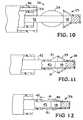
- FIG. 10shows the shape memory polymer actuator used in conjunction with a guide tube (catheter).
- FIG. 11shows an enhancement to the basic design.
- FIG. 12shows an enhancement to the basic design.
- FIG. 13shows an enhancement to the basic design.
- FIG. 14shows an enhancement to the basic design.
- FIGS. 15A, 15 B, and 15 Cillustrate integrating radio-opaque markers into the shape memory polymer actuator.
- FIG. 16illustrates a diagnostic sensor at the distal tip of the shape memory polymer actuator.
- FIG. 17shows a sensor attached, deposited or embedded in the distal end of the shape memory polymer actuator.
- FIG. 18shows light is coupled directly into the shape memory polymer actuator and aimed at the umbrella section where actuation is required.
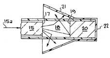
- FIG. 19shows use of multiple umbrellas.
- FIG. 20shows opposing umbrellas used to scrape the walls in both directions to contain more of the debris.
- FIG. 21shows different wavelengths, filters or transition temperatures for independent control of two shape memory polymer actuators.
- FIG. 22shows different wavelengths, filters or transition temperatures for independent control of two shape memory polymer actuators.
- FIG. 23shows end views of two umbrellas illustrating how the teeth along the outer rim of the two umbrellas interlock and provide improved scraping.
- FIG. 24shows teeth along the outer rim of an umbrella for easy interlocking and improved scraping.
- FIG. 25shows a snap type locking system where the rim of one cone snaps into the rim of the other to enclose the debris through optical actuation.
- FIG. 26shows barbs inside and along the rim help to hook and hold the debris.
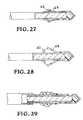
- FIG. 27shows a clamp holding the umbrella closed during transport.
- FIG. 28shows the umbrella opened.
- FIG. 29shows an undesired effect of tethers.
- FIG. 30shows an undesired effect of tethers.
- FIG. 31shows an improvement on tethers.
- FIG. 32shows independent control of two shape memory polymer actuators.
- FIG. 33is a conceptual illustration of a another embodiment of the present invention in a vessel with a blockage such as a blood clot.
- FIGS. 1, 2 , and 3 of the drawingsa medical application of an embodiment of an actuator constructed in accordance with the present invention is illustrated.
- a specific application of the present inventionis described, it is to be understood that the invention is intended to be general in nature, and can be employed wherever actuators are needed.
- the methods and devicesare general to all applications of actuation and control of a shaped memory material.
- the present inventionprovides an actuator system.
- the systemuses heat to activate a shape memory material.
- the shape memory materialwill change shape when heated above a transition temperature.
- the shape memory materialis adapted to move from a first position to a second position where it can perform a desired function.
- a method of removing matter from a vesselis described.
- a catheter with a shape memory materialis transported to the site of the matter to be removed.
- the shape memory materialis passed through or around the matter. Heat is utilized to activate the shape memory material and expand the shape memory material. By withdrawing the catheter and the shape memory material through said vessel the matter is carried from the vessel.
- the present inventioncan be used to remove blockages from many luminal structures.
- the shape memory materialcan be heated using various systems.
- the shape memory materialcan be heated as described in U.S. Pat. No. 5,911,737 for microfabricated therapeutic actuators, by Lee et al, patented Jun. 15, 1999 as follows: “Heating of the SMP tubing 20 can be accomplished via induced resistive heating of the end 22 of object 21 by an external wave field, such as by an associated magnetic or radio frequency (RF) source, provided of cause that the end 22 of object 21 is constructed of material inductive of resistance heating. External heating of the end 22 of object 21 can be carried out through electrical induction or electrothermal heating (through a dielectric lossy material on the end of the coil).
- RFradio frequency
- the shape memory materialcan also be heated using an optical system.
- the systemuses energy in the form of light guided by an optical fiber to a light, diffusing device that radiates the light into the shape memory material. The light is absorbed by the shape memory material and converted into heat.
- FIG. 1shows a vessel 10 with a blockage 11 .
- the blockagecould be a blood clot, plaque, other emboli, or other blockage.
- a support structure 12 with a shape memory material actuator 13 on its distal endis inserted through or around the blockage 11 .
- the shape memory material actuator 13is used to remove the blockage 11 from the vascular system.
- FIG. 2shows the expanded shape memory material actuator 13 .
- Actuationis achieved by heating the shape memory material.
- the shape memory materialcan be heated using various systems. These systems include induced resistive heating by an external wave field, such as by an associated magnetic or radio frequency (RF) source, external heating through electrical induction or electrothermal heating, with local or remote ultrasonics or other acoustic means of energy transfer, or by converting optical energy into thermal energy that allows the stored energy in the shape memory material to be released.
- RFradio frequency
- the heating of the SMPcan be accomplished by an operatively connected or embedded mechanism which is powered by the absorption of applied energy in the form of light, electric fields, magnetic fields, RF fields, EM waves, acoustic/ultrasound waves, electric current flow (DC: resistive heating, AC: inductive or dielectric heating), chemical reactions and/or other heating mechanisms such as nuclear heating ect.
- the optical energyis absorbed by the shape memory material and converted into thermal energy that heats the shape memory material above its transition temperature and the shape memory material moves to its primary shape, resulting in opto-mechanical actuation.
- FIG. 3shows that, when the shape memory material actuator is drawn backward it results in the removal of the blockage from the vessel 10 .
- the catheter with the shape memory material 13was transported to the site of the matter 11 to be removed.
- the shape memory material 13was passed through or around the matter 11 .
- Heatwas utilized to activate the shape memory material 13 and expand the shape memory material 13 .
- the shape memory material actuator systemhas significant utility, for example, the treatment cost of ischemic strokes is estimated to be $20 Billion/year.
- the support structure 12 shown in FIGS. 1 and 2uses an expanding opto-mechanical actuator system.
- the systemuses energy in the form of light guided by an optical fiber to a light diffusing device that radiates the light into the shape memory material.
- the lightis absorbed by the shape memory material and converted into heat.
- the shape memory materialwill change shape when heated above a transition temperature.
- the shape memory polymer (SMP) actuator systemis designated generally by the reference numeral 14 .
- the system 14is an opto-mechanical system that, similar to a guide wire that is commonly pushed through the blood clot, is fed through or around the clot and then actuated to open like an umbrella. The expanded opto-mechanical device is retracted and the blockage is removed.
- the systemincludes the following components:
- the optical fiber 15is typically sheathed in a buffer jacket 16 with additional material layers built up to form a biocompatible catheter.
- the fiberis multimode with typical core dimensions between 50-1000 ⁇ m.
- the distal end 17 of the fiber 15delivers light to a diffusing chamber 18 .
- the optical source 15 aprovides light energy through the optical fiber 15 .
- the optical source 15 acan be a light source coupled into an optical fiber. The light is radiated from the light source. The light is transmitted by the optical fiber 15 to the diffusing device. The diffusing device transmits the light to the shape memory material.
- the optical source 15 acan be various systems. For example, the optical source 15 a can be heated as described in U.S. Pat. No. 6,102,917, by Maitland et al, patented Aug. 15, 2000, as follows: “The catheter section 11 , extension section 14 , and control unit 15 are interconnected by optic fiber connectors 16 and 17 .
- Control unit 15includes a laser 18 , laser control or driving electronics and display panel assembly generally indicated at 19 , and connected as indicated at 20 to laser 18 .
- Laser 18is connected by optic fibers 21 and 22 via an optic fiber connector 23 to a fiber optic coupler 24 , such as a conventional 90/10 optical coupler, which is connected via an optic fiber 25 to optic fiber connector 17 .
- Coupler 24wherein 90 percent of the light passes through and 10 percent is bypassed, is also connected by an optic fiber 26 to a sensing photodetector 27 , which is connected to the display panel section of assembly 19 as indicated at 28 .
- Coupler 24is also connected by an optic fiber 29 to a source photodetector 30 , which is connected to the driving electronics or control section of assembly 19 , as indicated at 31 .
- Laser light (pulsed or continuous) from laser 18is transmitted, as indicated by pulses and arrows 32 , through optic fiber 21 , connector 23 , optic fiber 22 , coupler 24 , optic fiber 25 , connector 17 , an optic fiber 14 ′ in extension section 14 , connector 16 , and an optic fiber 11 ′ in catheter section 11 onto an end section of SMP microgripper 12 , which retains the coil 13 , causing heating of the material of microgripper 12 located around the coil”
- the disclosure of U.S. Pat. No. 6,102,917is incorporated herein by reference.
- the diffusing chamber 18distributes the light evenly around the circumference of the chamber and along the chamber length.
- the distal end 19 of the chamberis terminated with a reflective coating or plug 20 that maximizes the amount of light in the chamber.
- Typical lengths of the diffusing chamberare 100-5000 ⁇ m.
- a translucent plastic which scatters lightis one example of material that could be used in the diffusing chamber.
- SMP 21Shape Memory Polymer 21 —SMP materials are well known.
- U.S. Pat. No. 6,086,599 for micro devices using shape memory polymer patches for mated connections, by Lee et al, patented Jul. 11, 2000states: “SMP material is known in the art, and has been recently utilized as delivery means for medical or non-medical devices to inaccessible locations, such as blood vessels or inside a machine or tubing system.”
- U.S. Pat. No. 5,911,737 for microfabricated therapeutic actuators, by Lee et al, patented Jun. 15, 1999describes a SMP material as follows: “The SMP material, a polyurethane-based material that undergoes a phase transformation at a temperature (Tg).
- the SMP materialcan be constructed so as to be inert to any fluids of the human body, for example, and can be constructed to be responsive to various desired phase transformation temperatures, Tg, above which the material is soft and reshapable and then by cooling the material below the Tg, the material retains the reshaped configuration until it is again heated to above the Tg temperature at which time the SMP material returns to its original memory shape.”
- Tgphase transformation temperatures
- U.S. Pat. No. 6,102,917 for a shape memory polymer (SMP) gripper with a release sensing systemby Maitland et al, patented Aug. 15, 2000, describes a SMP material as follows: “SMP, a polyurethane-based material that undergoes a phase transformation at a temperature (Tg) of choice.
- a shape memory polymer resinconsisting essentially of a block copolymer having an A-B-A block structure in the polymer chain, and having an average molecular weight within the range of 10,000 to 1,000,000, wherein (a) block A is a polymer block comprising a homopolymer or a copolymer of a vinyl aromatic compound and/or a hydrogenated product thereof; (b) block B is a polymer block comprising a homopolymer or a copolymer of butadiene and/or a hydrogenated product thereof, the content of butadiene and/or the hydrogenated product thereof in block B being at least 80% by weight, and 80 to 91% of the linkages of the butadiene and/or the hydrogenated product thereof being 1,4-linkages; (c) at least 80% by weight of the conjugated diene in the block copolymer being hydrogenated; and (d) the block copolymer comprises 5 to 50% by weight of said block A; and a shape memory resin composition
- the SMP 21is attached to the outer fiber optic layer at its distal end 22 .
- the primary shape of the SMP 21is formed by heating the SMP 21 above its melting temperature as in an extrusion or molding processes.
- Typical lengths for the active region of the SMPare 100-5000 ⁇ m.
- the typical angle of the expanded SMPis between 0-90 degrees; however the angle could be beyond 90 degrees up to 180 degrees.
- This embodimentfocuses on the opto-mechanical methods and design necessary to develop a shape memory polymer (SMP) actuator 14 capable of removing blockages from a lumen.
- SMP actuationis based on the unique property of the shape memory polymer.
- This polymerpossesses a glass transformation temperature (T g ) above which the material enters a reversible glassy phase where it becomes soft and flexible and easy to reshape the material. Once cooled below T g , the shape is frozen in place and the material becomes hardened to over 200 times the elastic modulus of the glassy phase.
- T gglass transformation temperature
- the reshaped SMPcan be used to hold its shape until it is intentionally relaxed by heating the SMP above T g again.
- the systemuses energy in the form of light guided by an optical fiber to a light diffusing device that radiates the light into the shape memory polymer.
- the lightis absorbed by the shape memory polymer and converted into heat.
- the shape memory polymerwill change shape when heated above a transition temperature.
- the primary shape of the SMPis formed by heating the SMP above its melting temperature as in extrusion or molding processes.
- the SMPcan be made by mold injection under vacuum.
- the mold usedis a three part mold. The mold includes one male and two female sections. It is understood that the optical fiber 17 and diffusing chamber 18 are part of the shape memory polymer (SMP) actuator system 14 and these details will not be described in connection with additional embodiments of the present invention.
- FIG. 6is a schematic illustration showing a closed SMP actuator in its pre-expanded shape for an embodiment of the present invention.
- One issue with creating a working deviceis the method of collapsing the SMP such that it fills a minimum volume.
- the closed design and the method creating the closed stateare linked.
- the SMP 23was sliced along its length and then the SMP was wound around the diffusing chamber 24 .
- a tube approximately twice the diameter of the fiberwas pushed over the SMP 23 and simultaneously turned. This process was carried out in heated water that kept the SMP 23 above its transition temperature, Tg.
- the SMP 23was heated using 1 Watt from a 800 nm diode laser coupled into an 1 mm-core optical fiber. Prior to the laser being turned on, the SMP 23 is closed around the diffusing chamber 24 After the laser is turned on, light energy transmitted through the optical fiber 25 will cause the SMP 23 to open.
- the closed SMP 23 of the present inventioncan contain thrombolytic agents 26 that are released at the blockage site when the SMP actuator is opened. These agents can be liquid 26 held in the SMP 23 or coatings on the inner side 27 of the SMP 23 material.
- the closed stateis shown in FIG. 6 .
- the SMP 23can be meshed or otherwise have holes in it such that as a blockage volume fills the opened SMP 23 , the fluid 26 inside is displaced through the mesh.
- the expanded SMP 23can form a chamber to collect more blockage material.
- the SMP actuator systemis generally designated by the reference numeral 28 .
- the actuator 29is used in conjunction with a guide tube (catheter) 30 where the expanded actuator 29 with blockage material may be either locked around the guide tube 30 , with the whole assembly retracted from the lumen, or pulled through the guide tube 30 .
- a centering device 31is added to the optic fiber 32 just proximal to the SMP actuator 29 . This centering device 31 assists in guiding the expanded actuator 29 back into the guide tube 30 when the fiber optic core 32 is retracted relative to guide tube 30 .
- the guide tube 30 and expanded actuator 29are made such they can mechanically lock.
- This locking mechanismmay be active as in the case of the distal tip 33 of the guide tube 30 being an SMP actuator itself.
- the locking mechanismmay also be constructed out of SMP material (e.g. a second SMP that contracts around the expanded “umbrella” actuator).
- the guide tube (catheter) 30may be flared at its distal tip to easily accept the expanded actuator 29 . This enables collapsing the SMP actuator 29 .
- the SMP actuator 29 of the present inventioncan contain thrombolytic agents that are released at the blockage site when the SMP actuator 29 is opened. These agents can be liquid held in the SMP or coatings on the inner side of the SMP material.
- Dyemay be added to the SMP. Since the light absorption in the SMP actuator 29 facilitates the conversion from optical to thermal energies, the dye concentration may be adjusted so that the light is optimally absorbed in the SMP actuator. Variations of the dye concentration can be used to control heating uniformity and efficiency. Parameters that can be used to control the absorption is dye type, concentration, z-axis (along the length of the fiber) dye gradient, the p-axis distribution (around the circumference of the SMP), and r-axis (through the thickness of the SMP) dye gradient. As shown in the embodiment of FIG. 10, the SMP actuator 29 and optical fiber 32 are carried by a delivery catheter 30 . The delivery catheter 30 is contained in a guide catheter 35 .
- the method of use of the actuator 29is generally described as working in conjunction with a tube that both delivers the actuator to the blockage and works with the actuator to reshape or remove blockages.
- the basic design with the addition of a hollow balloon or centering device 34is shown in the embodiment of FIG. 10 . If the whole assembly (guide tube and actuator) is to be utilized, then the method may employ a mating between the tube and actuator as shown in the embodiment of in FIG. 8 . Alternatively, the device may be optimally used if the guide tube remains in place while the actuator (and other devices) is removed through the tube.
- Devicescan either contain the clot remotely, i.e., at the site of the SMP umbrella, or by retracting it into a docking stand at the distal end of a delivery or “tracker” catheter 30 shown in the embodiment of FIG. 10 .
- Remote captureis desired because the guide catheter is difficult, if not impossible, to pass through the carotid sinus or bulb.
- the docking standcan be accomplished by either using an activatable SMP flaring device such as shown in the embodiment of FIG. 9 or by using a hollow inflatable balloon 34 such as shown in the embodiment of FIG. 10 .
- the balloon conceptcould be used provide a local cap or lid on the proximal end of the SMP umbrella clot catcher while also providing a means to center the device upon retracting into the delivery or “tracker” catheter 30 .
- a tether 41to close the expanded SMP actuator 38 is shown.
- the proximal end of the SMP 39may be tethered such that tension on the tethers 41 results in the partial and/or complete collapse of the SMP (e.g. Reversible actuation, as shown in FIGS. 11 and 12.)
- This tetheringmay be accomplished by using connectors, similar to materials described above, that run parallel to the z-axis.
- the tethersmay be actuated by attaching their proximal end to a second tube 42 that may slide over the fiber optic 43 .
- FIGS. 13 and 14other systems for collapsing the SMP actuator 38 can be employed. Cutting away axial sections 40 of the material 39 of the SMP actuator 38 would also result in a collapsed state with a low cross-sectional area as show in FIGS. 13 and 14. The resulting radial sections are then connected along their circumference by wires or thread that would make the expanded actuator look more like a basket than an umbrella.
- the connective materialmay be located at multiple locations along the z-axis and may be attached to the SMP “petals” by adhesives, embedding or sandwiching the connections between the SMP and another material (possibly SMP).
- the collapsing of the SMPcan be facilitated by a light source.
- the collapse of the SMPmay be enhanced by turning the light source on.
- the heating of the SMP while employing a method for collapsing the SMP (such as tethers) and subsequently turning the light source offwill result in the SMP holding a second collapsed state. This may be used to contain the blockage between the SMP and diffusing chamber as well as reducing the proximal SMP diameter, which makes retracting through the guide tube more practical.
- the designmay be enhanced by integrating radio-opaque markers 44 , 45 , and 46 into the SMP as shown in the embodiments shown in FIGS. 15A, 15 B, and 15 C.
- These markers 44 , 45 , and 46 and their relative movement with respect to each othercan be used to determine the actuation state of the device (e.g. open or closed).
- the markersare imaged via fluoroscopy.
- a minimum of three markers placed symmetrically around the proximal edge of the SMPe.g. 3 markers—120° separation, 4 markers—90° separation, etc.
- FIG. 15Cshow an end view of the SMP 39 with three markers 44 near the outer circumference of the umbrella section.
- FIG. 15Billustrates circular markers in the umbrella section while the markers in FIG. 15C are arbitrarily shaped. These markers would be either attached to or embedded in the SMP. Their minimal size is dictated by current fluoroscope resolution. Since medical catheters typically have multiple radio-opaque markers, this device is likely to have other marker rings along its length, including one near the distal tip of the device.
- the devicemay employ radio-opaque markers for locating the distal and proximal ends of the SMP clot catcher as well as determining if the device is closed for insertion or open for clot entrapment. These radio-opaque markers would be accomplished by localized doping of the SMP with a radio-opaque metal such as platinum or other heavy, yet biocompatible element.
- the basic devicemay be enhanced by adding a diagnostic sensor 47 at the distal tip of the actuator. Since the method-of-use includes pushing the device through or around a blockage, a sensor 47 on the distal tip allows for the interrogation of the environment distal to the blockage. In medical applications, for example, this could include a diagnostic that would measure the viability of the distal vessel relative to reinstated blood flow. Since reintroducing blood to necrotic tissue will result in a potentially worse medical condition, a sensor that would help determine the health of the vessel wall would be extremely useful.
- the sensormay be any type but is likely to be light based.
- wavelengths and wavelength-specific reflective coatings 47 benable a device to be built that keeps the heating wavelength(s) confined to the diffusing chamber and allows diagnostic wavelengths to pass to the distal tip and back.
- the same wavelength(s)may be used for both actuating the SMP and interrogating the diagnostic.
- instrumentation techniqueslike heterodyne detection, interference or fluorescence may be useful in isolating the optical changes to the sensor at the distal tip.
- a sensor 48can be attached, deposited or embedded in the distal end of the device as shown in FIG. 17 .
- a shaped reflector 50 a shown in FIG. 18will aim the light uniformly into the SMP umbrella section 49 b and light delivery is maximized by reflective coatings 50 b on both the fiber circumference and the SMP.
- Reflective coatings 50 Bcould exist on all exterior surfaces (making use of any variety of coating techniques) while the internal interface between the fiber end 51 and SMP remains protected from such reflective coating.
- multiple umbrellas 52are used.
- the final umbrellawould likely have the least porosity (or smallest holes for fluid to pass through) to catch the smaller particles.
- Multiple umbrellasare used to improve the probability of catching all the debris.
- FIG. 20instead of having a guide tube for trapping the blockage (before extraction) it is possible to make use of an opposing SMP umbrella 53 to minimize the initial size of the device and maximize the maneuverability during insertion.
- the outer rim or edge of the umbrellais strong in only one direction.
- Opposing umbrellas 53 and 54can be used to scrape the walls in both directions and contain more of the debris.
- the opposing umbrella 53(shown on the left in FIG. 20) can move and lock with the main umbrella.
- the opposing umbrellacould ride on a separate sleeve with independent illumination means or an SMP device could cause the translation, eliminating the need for axial translations between the fiber and a sleeve or tube.
- the SMP methodis illustrated in FIGS. 21 and 22. Different wavelengths and filters or having different transition temperatures would enable independent control of the two SMP devices.
- the same or different wavelengthscan be used with the two SMP devices 55 and 56 shown (with the same or different transition temperatures) to actuate the umbrellas and interlock to enclosed the material that is to be extracted.
- FIG. 23shows end views of the two umbrellas positioned adjacent each other to illustrate how the teeth along the outer rim of the two umbrellas interlock and provide improved scraping. Teeth 57 and 58 along the outer rim of the umbrella can make for easy interlocking and may be designed for improved scraping. FIG. 23 shows a triangular tooth design 57 .
- FIG. 24shows the two umbrellas positioned together illustrating how the teeth along the outer rim of the two umbrellas interlock.
- FIG. 24shows a rounded tooth design 58 .
- FIG. 25shows a snap type locking method where the rim of one cone 59 snaps into the rim of the other cone 60 to enclose the debris through optical actuation.
- the cones 59 and 60are forced together by the expanding sleeve 60 a and the rim of one cone 59 snaps into the other cone 60 .
- FIG. 26Another embodiment, shown in FIG. 26, includes a barbed design 61 inside the umbrella. This will hook the obstruction and reduce the possibility of its escape.
- the barbs 61 inside and along the rimhelp to hook and hold the debris.
- FIGS. 27 and 28Another embodiment, shown in FIGS. 27 and 28, includes an SMP clamp 62 utilized to hold the pre-opened umbrella 63 in its closed position throughout transport. This allows for positive and negative axial translation of the device through the passageways without opening the umbrella.
- the clamp 62holds the umbrella 63 closed during transport.
- the clamp 62is opened and the pre-opened umbrella 63 is allowed to move to its expanded state.
- An SMPis used to release the clamp 63 .
- FIGS. 29 and 30An undesired effect of tethers is illustrated in FIGS. 29 and 30 where the tethers push the debris away. As illustrated in FIGS. 29 and 30, these tethers would have to cut through or circumvent the blockage to be helpful. Failure to do so could actually eject the blockage.
- FIG. 31Another embodiment that includes a tether 64 is illustrated in FIG. 31 .
- An extension section 65 a of the umbrellaprevents the debris from being ejected as it closes down on the blockage when tether 64 is pulled.
- a second SMP device 65 bcould be use to close an opened umbrella.
- the second SMP 65 bcould have a different transition temperature but for more independent control of the SMPs, different wavelengths or polarizations of light could be used in conjunction with filters or polarizers. In general, maintaining polarization in fibers is problematic and control at the output end with polarizers and electronically controlled retarders make the system even more complex.
- Using two different wavelengths to open then close the umbrellais illustrated in FIG. 32 where an elongating sleeve puts pressure on the umbrella for closure.
- the second SMP device 65 bshown here as an elongating sleeve, puts pressure on the umbrella to close it around the debris.
- Bistabilitywas mentioned in regards to using tethers to close the umbrella.
- the device in FIG. 32is bistable without tethers. If you heat both SMPs until they become soft, then depending on which cools first decides the mechanical state they will end up in. For example, turn the umbrella actuating light off first and it cools first, pushing away the sleeve and assuming an open umbrella shape. Turn off the closure device light first and the closure device pushes on the umbrella to close it somewhat. Turn on the umbrella actuating light and now you can completely close and encapsulate the now soft umbrella.
- a vessel 71contains a blockage 73 .
- the blockage 73could be a blood clot, plaque, other emboli, or other blockage.
- a support structure 72 with a shape memory material actuator 74 on its distal endis inserted through or around the blockage 73 .
- the shape memory material actuator 73is used to remove the blockage 73 from the vascular system. Actuation is achieved by heating the shape memory material 74 .
- the shape memory materialcan be heated using various systems. These systems include induced resistive heating by an external wave field, such as by an associated magnetic or radio frequency (RF) source, external heating through electrical induction or electrothermal heating, with local or remote ultrasonics or other acoustic means of energy transfer, or by converting optical energy into thermal energy that allows the stored energy in the shape memory material to be released.
- An external energy source 75transmits energy, in the form of waves 76 , to the SMP actuator 74 .
- the external source 75may produce heating by an external wave field, such as by an associated magnetic or radio frequency (RF) source, or by remote ultrasonics or other acoustic means of energy transfer.
- the energyis absorbed by the shape memory material and converted into thermal energy that heats the shape memory material above its transition temperature and the shape memory material moves to its primary shape, resulting in mechanical actuation.
- the shape memory material actuator 74is drawn backward it results in the removal of the blockage 73 from the vessel 71 .
Landscapes
- Health & Medical Sciences (AREA)
- Surgery (AREA)
- Life Sciences & Earth Sciences (AREA)
- Medical Informatics (AREA)
- Animal Behavior & Ethology (AREA)
- Engineering & Computer Science (AREA)
- Biomedical Technology (AREA)
- Heart & Thoracic Surgery (AREA)
- Vascular Medicine (AREA)
- Molecular Biology (AREA)
- Nuclear Medicine, Radiotherapy & Molecular Imaging (AREA)
- General Health & Medical Sciences (AREA)
- Public Health (AREA)
- Veterinary Medicine (AREA)
- Orthopedic Medicine & Surgery (AREA)
- Surgical Instruments (AREA)
- Media Introduction/Drainage Providing Device (AREA)
- Endoscopes (AREA)
Abstract
Description
Claims (64)
Priority Applications (4)
| Application Number | Priority Date | Filing Date | Title |
|---|---|---|---|
| US09/761,023US6740094B2 (en) | 2000-11-06 | 2001-01-16 | Shape memory polymer actuator and catheter |
| PCT/US2001/049939WO2002051488A2 (en) | 2000-11-06 | 2001-10-19 | Shape memory polymer actuator and catheter |
| AU2002245168AAU2002245168A1 (en) | 2000-11-06 | 2001-10-19 | Shape memory polymer actuator and catheter |
| US10/713,622US7291154B2 (en) | 2000-11-06 | 2003-11-13 | Shape memory polymer actuator and catheter |
Applications Claiming Priority (2)
| Application Number | Priority Date | Filing Date | Title |
|---|---|---|---|
| US24629300P | 2000-11-06 | 2000-11-06 | |
| US09/761,023US6740094B2 (en) | 2000-11-06 | 2001-01-16 | Shape memory polymer actuator and catheter |
Related Child Applications (1)
| Application Number | Title | Priority Date | Filing Date |
|---|---|---|---|
| US10/713,622DivisionUS7291154B2 (en) | 2000-11-06 | 2003-11-13 | Shape memory polymer actuator and catheter |
Publications (2)
| Publication Number | Publication Date |
|---|---|
| US20020095169A1 US20020095169A1 (en) | 2002-07-18 |
| US6740094B2true US6740094B2 (en) | 2004-05-25 |
Family
ID=26937854
Family Applications (2)
| Application Number | Title | Priority Date | Filing Date |
|---|---|---|---|
| US09/761,023Expired - LifetimeUS6740094B2 (en) | 2000-11-06 | 2001-01-16 | Shape memory polymer actuator and catheter |
| US10/713,622Expired - LifetimeUS7291154B2 (en) | 2000-11-06 | 2003-11-13 | Shape memory polymer actuator and catheter |
Family Applications After (1)
| Application Number | Title | Priority Date | Filing Date |
|---|---|---|---|
| US10/713,622Expired - LifetimeUS7291154B2 (en) | 2000-11-06 | 2003-11-13 | Shape memory polymer actuator and catheter |
Country Status (3)
| Country | Link |
|---|---|
| US (2) | US6740094B2 (en) |
| AU (1) | AU2002245168A1 (en) |
| WO (1) | WO2002051488A2 (en) |
Cited By (56)
| Publication number | Priority date | Publication date | Assignee | Title |
|---|---|---|---|---|
| US20030212337A1 (en)* | 2002-05-09 | 2003-11-13 | Spiration, Inc. | Automated provision of information related to air evacuation from a chest cavity |
| US20030236533A1 (en)* | 2002-06-20 | 2003-12-25 | The Regents Of The University Of California | Shape memory polymer actuator and catheter |
| US20040074062A1 (en)* | 2002-10-19 | 2004-04-22 | Stanford Thomas B. | Releasable fastener system |
| US20040074068A1 (en)* | 2002-10-19 | 2004-04-22 | Browne Alan Lampe | Releasable fastener system |
| US20040074063A1 (en)* | 2002-10-19 | 2004-04-22 | Golden Mark A. | Releasable fastener system |
| US20040074071A1 (en)* | 2002-10-19 | 2004-04-22 | Golden Mark A. | Releasable fastener systems and processes |
| US20040074070A1 (en)* | 2002-10-19 | 2004-04-22 | Momoda Leslie A. | Releasable fastening system based on ionic polymer metal composites and method of use |
| US20040074067A1 (en)* | 2002-10-19 | 2004-04-22 | Browne Alan Lampe | Electrostatically releasable fastening system and method of use |
| US20040117955A1 (en)* | 2002-10-19 | 2004-06-24 | William Barvosa-Carter | Releasable fastener systems and processes |
| US20040194261A1 (en)* | 2002-10-19 | 2004-10-07 | General Motors Corporation | Magnetorheological nanocomposite elastomer for releasable attachment applications |
| US20040260333A1 (en)* | 1997-11-12 | 2004-12-23 | Dubrul William R. | Medical device and method |
| US20050065545A1 (en)* | 2003-09-23 | 2005-03-24 | Scimed Life Systems, Inc. | External activation of vaso-occlusive implants |
| US20050065501A1 (en)* | 2003-09-23 | 2005-03-24 | Scimed Life Systems, Inc. | Energy activated vaso-occlusive devices |
| US20050071399A1 (en)* | 2003-09-26 | 2005-03-31 | International Business Machines Corporation | Pseudo-random binary sequence checker with automatic synchronization |
| US20050228417A1 (en)* | 2004-03-26 | 2005-10-13 | Teitelbaum George P | Devices and methods for removing a matter from a body cavity of a patient |
| US20050288777A1 (en)* | 2004-06-29 | 2005-12-29 | Rhee Richard S | Thermal conductor for adjustable cardiac valve implant |
| US20060009785A1 (en)* | 2003-11-13 | 2006-01-12 | The Regents Of The University Of California | Shape memory polymer medical device |
| US20060015178A1 (en)* | 2004-07-15 | 2006-01-19 | Shahram Moaddeb | Implants and methods for reshaping heart valves |
| US7013538B2 (en) | 2002-10-19 | 2006-03-21 | General Motors Corporation | Electroactive polymer releasable fastening system and method of use |
| US7032282B2 (en) | 2002-10-19 | 2006-04-25 | General Motors Corporation | Releasable fastener system |
| US20060127561A1 (en)* | 2001-12-18 | 2006-06-15 | Stephen Griffin | Guide wire with adjustable flexibility |
| US20060206140A1 (en)* | 2005-02-24 | 2006-09-14 | Samuel Shaolian | Adjustable embolic aneurysm coil |
| US20060212113A1 (en)* | 2005-02-24 | 2006-09-21 | Shaolian Samuel M | Externally adjustable endovascular graft implant |
| US20060241747A1 (en)* | 2005-04-21 | 2006-10-26 | Emanuel Shaoulian | Dynamically adjustable implants and methods for reshaping tissue |
| US20060261109A1 (en)* | 2005-05-18 | 2006-11-23 | Browne Alan L | Cargo container including an active material based releasable fastener system |
| US20070055368A1 (en)* | 2005-09-07 | 2007-03-08 | Richard Rhee | Slotted annuloplasty ring |
| US20080009831A1 (en)* | 2004-12-03 | 2008-01-10 | Scimed Life Systems, Inc. | Selectively flexible catheter and method of use |
| US20080019657A1 (en)* | 2005-06-30 | 2008-01-24 | The Regents Of The University Of California | System for diffusing light from an optical fiber or light guide |
| US20080021416A1 (en)* | 2004-10-07 | 2008-01-24 | Keio University | Thin tube which can be hyperflexed by light |
| US20080045881A1 (en)* | 2004-03-26 | 2008-02-21 | University Of Southern California | Devices and methods for removing a matter from a body cavity of a patient |
| US20080183285A1 (en)* | 2004-06-29 | 2008-07-31 | Micardia Corporation | Adjustable cardiac valve implant with selective dimensional adjustment |
| US7536228B2 (en) | 2006-03-24 | 2009-05-19 | Micardia Corporation | Activation device for dynamic ring manipulation |
| US20090248141A1 (en)* | 2006-03-30 | 2009-10-01 | The Regents Of The University Of Colorado | Shape Memory Polymer Medical Devices |
| US7611524B1 (en)* | 2005-09-27 | 2009-11-03 | Lawrence Livermore National Security, Llc | Guide wire extension for shape memory polymer occlusion removal devices |
| US20100152839A1 (en)* | 2008-10-29 | 2010-06-17 | The Regents Of The University Of Colorado, A Body Corporate | Shape Memory Polymer Prosthetic Medical Device |
| US20100185274A1 (en)* | 2005-12-16 | 2010-07-22 | Micardia Corporation | Adjustable prosthetic valve implant |
| US20100192959A1 (en)* | 2006-12-19 | 2010-08-05 | The Regents Of The University Of Colorado, A Body Corporate | Shape memory polymer-based transcervical device for permanent or temporary sterilization |
| US20110230962A1 (en)* | 2006-12-04 | 2011-09-22 | Micardia Corporation | Dynamically adjustable suture and chordae tendinae |
| US20120035646A1 (en)* | 2010-08-06 | 2012-02-09 | Abbott Laboratories Vascular Enterprises Limited | Bistable body lumen filter anchors |
| US8398672B2 (en) | 2003-11-12 | 2013-03-19 | Nitinol Devices And Components, Inc. | Method for anchoring a medical device |
| US9186487B2 (en) | 1997-11-12 | 2015-11-17 | Genesis Technologies Llc | Medical device and method |
| US9427493B2 (en) | 2011-03-07 | 2016-08-30 | The Regents Of The University Of Colorado | Shape memory polymer intraocular lenses |
| US9476412B2 (en) | 2013-03-14 | 2016-10-25 | Lawrence Livermore National Security, Llc | Resistively heated shape memory polymer device |
| US9498604B2 (en) | 1997-11-12 | 2016-11-22 | Genesis Technologies Llc | Medical device and method |
| US9561094B2 (en) | 2010-07-23 | 2017-02-07 | Nfinium Vascular Technologies, Llc | Devices and methods for treating venous diseases |
| US9649211B2 (en) | 2009-11-04 | 2017-05-16 | Confluent Medical Technologies, Inc. | Alternating circumferential bridge stent design and methods for use thereof |
| US9731045B2 (en) | 2005-04-01 | 2017-08-15 | The Regents Of The University Of Colorado | Shape memory polymer |
| US9808252B2 (en) | 2009-04-02 | 2017-11-07 | Endoshape, Inc. | Vascular occlusion devices |
| US10092427B2 (en) | 2009-11-04 | 2018-10-09 | Confluent Medical Technologies, Inc. | Alternating circumferential bridge stent design and methods for use thereof |
| US10107270B2 (en) | 2013-03-14 | 2018-10-23 | Lawrence Livermore National Security, Llc | Bidirectional shape memory device |
| EP3417890A1 (en) | 2017-06-23 | 2018-12-26 | National Taipei University of Technology | Shape memory spacer fabric composite |
| US10201351B2 (en) | 2011-09-30 | 2019-02-12 | Endoshape, Inc. | Continuous embolic coil and methods and devices for delivery of the same |
| US10499935B2 (en) | 2015-04-08 | 2019-12-10 | Lawrence Livermore National Security, Llc | Shape memory embolectomy devices and systems |
| US10603043B2 (en) | 2012-01-17 | 2020-03-31 | Endoshape, Inc. | Occlusion device for a vascular or biological lumen |
| US11266414B2 (en) | 2014-06-04 | 2022-03-08 | Vascular Development Corp, Llc | Low radial force vascular device and method of occlusion |
| US12440650B2 (en) | 2023-02-27 | 2025-10-14 | Vascular Development Corp, Llc | Augmented delivery catheter and method |
Families Citing this family (88)
| Publication number | Priority date | Publication date | Assignee | Title |
|---|---|---|---|---|
| DE69839888D1 (en)* | 1997-11-12 | 2008-09-25 | Genesis Technologies Llc | DEVICE FOR REMOVING OCCLUSIONS IN BIOLOGICAL PASSES |
| US20070135907A1 (en)* | 2003-10-02 | 2007-06-14 | The Regents Of The University Of California | Stent with expandable foam |
| US8133256B2 (en) | 2003-10-02 | 2012-03-13 | Lawrence Livermore National Security, Llc | Shape memory polymer foams for endovascular therapies |
| US7591834B2 (en)* | 2004-03-26 | 2009-09-22 | Lawrence Livermore National Security, Llc | Shape memory system with integrated actuation using embedded particles |
| WO2006137267A1 (en)* | 2005-06-20 | 2006-12-28 | Terumo Kabushiki Kaisha | Wire for eliminating foreign matter in blood vessel and medical implement |
| WO2008048234A2 (en) | 2005-08-26 | 2008-04-24 | North Carolina State University | Inhaler system for targeted maximum drug-aerosol delivery |
| US20070299456A1 (en)* | 2006-06-06 | 2007-12-27 | Teague James A | Light responsive medical retrieval devices |
| US8348973B2 (en)* | 2006-09-06 | 2013-01-08 | Covidien Lp | Bioactive substance in a barbed suture |
| JP5254569B2 (en)* | 2007-05-22 | 2013-08-07 | ルネサスエレクトロニクス株式会社 | Semiconductor device and method of fusing semiconductor device |
| US9125552B2 (en)* | 2007-07-31 | 2015-09-08 | Ethicon Endo-Surgery, Inc. | Optical scanning module and means for attaching the module to medical instruments for introducing the module into the anatomy |
| EP2180839A4 (en)* | 2007-08-06 | 2013-08-28 | Michael R Henson | Thrombectomy system and method |
| US8152775B2 (en)* | 2007-10-17 | 2012-04-10 | Tyco Healthcare Group Lp | Access port using shape altering anchor |
| US20090105659A1 (en)* | 2007-10-17 | 2009-04-23 | Tyco Healthcare Group Lp | Anchoring cannula |
| US20090105691A1 (en)* | 2007-10-17 | 2009-04-23 | Tyco Healthcare Group Lp | Access port using shape memory anchor |
| US8454653B2 (en) | 2008-02-20 | 2013-06-04 | Covidien Lp | Compound barb medical device and method |
| US8888810B2 (en) | 2008-02-20 | 2014-11-18 | Covidien Lp | Compound barb medical device and method |
| US20090270714A1 (en)* | 2008-04-24 | 2009-10-29 | Medtronic Vascular, Inc | Device to Treat Chronic Total Occlusions Using Energy Imparted By External Imaging |
| EP2341845B1 (en) | 2008-07-22 | 2016-01-06 | Neuravi Limited | Clot capture systems |
| US9402707B2 (en) | 2008-07-22 | 2016-08-02 | Neuravi Limited | Clot capture systems and associated methods |
| US8864792B2 (en) | 2008-08-29 | 2014-10-21 | Rapid Medical, Ltd. | Device and method for clot engagement |
| US8758364B2 (en) | 2008-08-29 | 2014-06-24 | Rapid Medical Ltd. | Device and method for clot engagement and capture |
| US9034008B2 (en) | 2008-08-29 | 2015-05-19 | Rapid Medical Ltd. | Device and method involving stabilization during clot removal |
| US9005237B2 (en) | 2008-08-29 | 2015-04-14 | Rapid Medical Ltd. | Device and method for clot capture |
| US8034095B2 (en) | 2008-08-29 | 2011-10-11 | Cook Medical Technologies Llc | Intraluminal system for retrieving an implantable medical device |
| US20100204729A1 (en)* | 2008-09-11 | 2010-08-12 | Ahmad Robert Hadba | Tapered Looped Suture |
| US8323316B2 (en) | 2008-10-09 | 2012-12-04 | Covidien Lp | Knotted suture end effector |
| WO2010046897A1 (en)* | 2008-10-24 | 2010-04-29 | Rapid Medical Ltd. | Embolectomy device containing a distal and proximal effecter |
| US20110152920A1 (en)* | 2008-12-02 | 2011-06-23 | Rapid Medical Ltd. | Embolectomy device |
| US8206291B2 (en) | 2009-03-27 | 2012-06-26 | Tyco Healthcare Group Lp | Portal device |
| DK3117784T3 (en)* | 2009-07-08 | 2019-04-08 | Sanuwave Inc | USE OF INTRACORPORAL PRESSURE SHOCK WAVES IN MEDICINE |
| US9149605B2 (en)* | 2009-07-28 | 2015-10-06 | Clement Kleinstreuer | Methods and devices for targeted injection of microspheres |
| ES2683943T3 (en) | 2010-10-22 | 2018-09-28 | Neuravi Limited | Clot capture and removal system |
| US12076037B2 (en) | 2011-03-09 | 2024-09-03 | Neuravi Limited | Systems and methods to restore perfusion to a vessel |
| US11259824B2 (en) | 2011-03-09 | 2022-03-01 | Neuravi Limited | Clot retrieval device for removing occlusive clot from a blood vessel |
| EP4566553A3 (en) | 2011-03-09 | 2025-08-06 | Neuravi Limited | A clot retrieval device for removing occlusive clot from a blood vessel |
| US9381062B2 (en) | 2012-05-31 | 2016-07-05 | Covidien Lp | Electro-mechanical intravascular device |
| US20150289892A1 (en)* | 2012-11-21 | 2015-10-15 | The Hong Kong University Of Science And Technology | Low Force Thrombectomy Device |
| JP5819387B2 (en)* | 2013-01-09 | 2015-11-24 | 富士フイルム株式会社 | Photoacoustic image generating apparatus and insert |
| US9642635B2 (en) | 2013-03-13 | 2017-05-09 | Neuravi Limited | Clot removal device |
| US9433429B2 (en) | 2013-03-14 | 2016-09-06 | Neuravi Limited | Clot retrieval devices |
| ES2708786T3 (en) | 2013-03-14 | 2019-04-11 | Neuravi Ltd | Clot recovery device to remove occlusive clots from a blood vessel |
| WO2014140092A2 (en) | 2013-03-14 | 2014-09-18 | Neuravi Limited | Devices and methods for removal of acute blockages from blood vessels |
| US10285720B2 (en) | 2014-03-11 | 2019-05-14 | Neuravi Limited | Clot retrieval system for removing occlusive clot from a blood vessel |
| JP6595513B2 (en) | 2014-06-13 | 2019-10-23 | ニューラヴィ・リミテッド | Device for removal of acute occlusions from blood vessels |
| US10792056B2 (en) | 2014-06-13 | 2020-10-06 | Neuravi Limited | Devices and methods for removal of acute blockages from blood vessels |
| US10265086B2 (en) | 2014-06-30 | 2019-04-23 | Neuravi Limited | System for removing a clot from a blood vessel |
| US11253278B2 (en) | 2014-11-26 | 2022-02-22 | Neuravi Limited | Clot retrieval system for removing occlusive clot from a blood vessel |
| EP3682821B1 (en) | 2014-11-26 | 2022-05-11 | Neuravi Limited | A clot retrieval device for removing an occlusive clot from a blood vessel |
| US10617435B2 (en) | 2014-11-26 | 2020-04-14 | Neuravi Limited | Clot retrieval device for removing clot from a blood vessel |
| WO2016138424A1 (en)* | 2015-02-28 | 2016-09-01 | Transmed7, Llc | Devices and methods for percutaneous transluminal angioplasty and atherectomy intervention procedures |
| AU2016320844B2 (en)* | 2015-09-07 | 2020-11-12 | Filterlex Medical Ltd. | Intra-aortic emboli protection filter device |
| US11576679B2 (en) | 2016-07-29 | 2023-02-14 | The Texas A&M University System | Heated endovascular catheter injection device |
| EP3500191B1 (en) | 2016-08-17 | 2020-09-23 | Neuravi Limited | A clot retrieval system for removing occlusive clot from a blood vessel |
| EP3509509B1 (en) | 2016-09-06 | 2021-03-31 | Neuravi Limited | A clot retrieval device for removing occlusive clot from a blood vessel |
| ES2983820T3 (en) | 2017-03-14 | 2024-10-25 | Shape Memory Medical Inc | Shape memory polymer foams for sealing a space around valves |
| US10751934B2 (en)* | 2018-02-01 | 2020-08-25 | Divergent Technologies, Inc. | Apparatus and methods for additive manufacturing with variable extruder profiles |
| US20210153999A1 (en)* | 2018-05-22 | 2021-05-27 | Filterlex Medical Ltd. | Intra-aortic embolic protection filter device |
| US10842498B2 (en) | 2018-09-13 | 2020-11-24 | Neuravi Limited | Systems and methods of restoring perfusion to a vessel |
| US11406416B2 (en) | 2018-10-02 | 2022-08-09 | Neuravi Limited | Joint assembly for vasculature obstruction capture device |
| ES2910600T3 (en) | 2019-03-04 | 2022-05-12 | Neuravi Ltd | Powered Clot Recovery Catheter |
| US11103324B2 (en)* | 2019-08-28 | 2021-08-31 | Massachusetts Institute Of Technology | Magnetically steerable continuum robotic guidewires for neurovascular applications |
| EP3791815B1 (en) | 2019-09-11 | 2024-06-26 | Neuravi Limited | Expandable mouth catheter |
| US11712231B2 (en) | 2019-10-29 | 2023-08-01 | Neuravi Limited | Proximal locking assembly design for dual stent mechanical thrombectomy device |
| US11779364B2 (en) | 2019-11-27 | 2023-10-10 | Neuravi Limited | Actuated expandable mouth thrombectomy catheter |
| US11839725B2 (en) | 2019-11-27 | 2023-12-12 | Neuravi Limited | Clot retrieval device with outer sheath and inner catheter |
| US11517340B2 (en) | 2019-12-03 | 2022-12-06 | Neuravi Limited | Stentriever devices for removing an occlusive clot from a vessel and methods thereof |
| US11633198B2 (en) | 2020-03-05 | 2023-04-25 | Neuravi Limited | Catheter proximal joint |
| US11944327B2 (en) | 2020-03-05 | 2024-04-02 | Neuravi Limited | Expandable mouth aspirating clot retrieval catheter |
| US11883043B2 (en) | 2020-03-31 | 2024-01-30 | DePuy Synthes Products, Inc. | Catheter funnel extension |
| US11759217B2 (en) | 2020-04-07 | 2023-09-19 | Neuravi Limited | Catheter tubular support |
| US11730501B2 (en) | 2020-04-17 | 2023-08-22 | Neuravi Limited | Floating clot retrieval device for removing clots from a blood vessel |
| US11871946B2 (en) | 2020-04-17 | 2024-01-16 | Neuravi Limited | Clot retrieval device for removing clot from a blood vessel |
| US11717308B2 (en) | 2020-04-17 | 2023-08-08 | Neuravi Limited | Clot retrieval device for removing heterogeneous clots from a blood vessel |
| US11737771B2 (en) | 2020-06-18 | 2023-08-29 | Neuravi Limited | Dual channel thrombectomy device |
| US11937836B2 (en) | 2020-06-22 | 2024-03-26 | Neuravi Limited | Clot retrieval system with expandable clot engaging framework |
| US11395669B2 (en) | 2020-06-23 | 2022-07-26 | Neuravi Limited | Clot retrieval device with flexible collapsible frame |
| US11439418B2 (en) | 2020-06-23 | 2022-09-13 | Neuravi Limited | Clot retrieval device for removing clot from a blood vessel |
| WO2022060379A1 (en)* | 2020-09-21 | 2022-03-24 | Imcat, Inc. | Hybrid thrombectomy device and process |
| US11864781B2 (en) | 2020-09-23 | 2024-01-09 | Neuravi Limited | Rotating frame thrombectomy device |
| US11937837B2 (en) | 2020-12-29 | 2024-03-26 | Neuravi Limited | Fibrin rich / soft clot mechanical thrombectomy device |
| US12029442B2 (en) | 2021-01-14 | 2024-07-09 | Neuravi Limited | Systems and methods for a dual elongated member clot retrieval apparatus |
| US11872354B2 (en) | 2021-02-24 | 2024-01-16 | Neuravi Limited | Flexible catheter shaft frame with seam |
| US12064130B2 (en) | 2021-03-18 | 2024-08-20 | Neuravi Limited | Vascular obstruction retrieval device having sliding cages pinch mechanism |
| US11974764B2 (en) | 2021-06-04 | 2024-05-07 | Neuravi Limited | Self-orienting rotating stentriever pinching cells |
| US11937839B2 (en) | 2021-09-28 | 2024-03-26 | Neuravi Limited | Catheter with electrically actuated expandable mouth |
| US12011186B2 (en) | 2021-10-28 | 2024-06-18 | Neuravi Limited | Bevel tip expandable mouth catheter with reinforcing ring |
| WO2024130075A1 (en)* | 2022-12-15 | 2024-06-20 | W. L. Gore & Associates, Inc. | Devices and systems for thrombus treatment |
| CN117338496B (en)* | 2023-12-04 | 2024-02-09 | 北京久事神康医疗科技有限公司 | Drug stent conveying device |
Citations (7)
| Publication number | Priority date | Publication date | Assignee | Title |
|---|---|---|---|---|
| US4919133A (en) | 1988-08-18 | 1990-04-24 | Chiang Tien Hon | Catheter apparatus employing shape memory alloy structures |
| WO1992016153A1 (en) | 1991-03-19 | 1992-10-01 | Roevin Trades Limited | Extraction devices |
| US5895398A (en)* | 1996-02-02 | 1999-04-20 | The Regents Of The University Of California | Method of using a clot capture coil |
| US5911737A (en)* | 1997-02-28 | 1999-06-15 | The Regents Of The University Of California | Microfabricated therapeutic actuators |
| WO2000030523A2 (en) | 1998-11-25 | 2000-06-02 | Israel Aircraft Industries | Temporary stent system with shape memory heating apparatus and method of use |
| US6102917A (en)* | 1998-07-15 | 2000-08-15 | The Regents Of The University Of California | Shape memory polymer (SMP) gripper with a release sensing system |
| US20020072764A1 (en) | 2000-06-29 | 2002-06-13 | Concentric Medical, Inc. | Systems, method and devices for removing obstructions from a blood vessel |
Family Cites Families (9)
| Publication number | Priority date | Publication date | Assignee | Title |
|---|---|---|---|---|
| DE8910603U1 (en) | 1989-09-06 | 1989-12-07 | Günther, Rolf W., Prof. Dr. | Device for removing blood clots from arteries and veins |
| US5836868A (en) | 1992-11-13 | 1998-11-17 | Scimed Life Systems, Inc. | Expandable intravascular occlusion material removal devices and methods of use |
| US5902313A (en)* | 1994-03-09 | 1999-05-11 | Redha; Falah | Medical instrument for atherectomy |
| US5645564A (en) | 1995-05-22 | 1997-07-08 | Regents Of The University Of California | Microfabricated therapeutic actuator mechanisms |
| AU690862B2 (en) | 1995-12-04 | 1998-04-30 | Target Therapeutics, Inc. | Fibered micro vaso-occlusive devices |
| US5846247A (en)* | 1996-11-15 | 1998-12-08 | Unsworth; John D. | Shape memory tubular deployment system |
| US6296622B1 (en)* | 1998-12-21 | 2001-10-02 | Micrus Corporation | Endoluminal device delivery system using axially recovering shape memory material |
| US6102932A (en)* | 1998-12-15 | 2000-08-15 | Micrus Corporation | Intravascular device push wire delivery system |
| US6086599A (en) | 1999-02-08 | 2000-07-11 | The Regents Of The University Of California | Micro devices using shape memory polymer patches for mated connections |
- 2001
- 2001-01-16USUS09/761,023patent/US6740094B2/ennot_activeExpired - Lifetime
- 2001-10-19WOPCT/US2001/049939patent/WO2002051488A2/enactiveApplication Filing
- 2001-10-19AUAU2002245168Apatent/AU2002245168A1/ennot_activeAbandoned
- 2003
- 2003-11-13USUS10/713,622patent/US7291154B2/ennot_activeExpired - Lifetime
Patent Citations (7)
| Publication number | Priority date | Publication date | Assignee | Title |
|---|---|---|---|---|
| US4919133A (en) | 1988-08-18 | 1990-04-24 | Chiang Tien Hon | Catheter apparatus employing shape memory alloy structures |
| WO1992016153A1 (en) | 1991-03-19 | 1992-10-01 | Roevin Trades Limited | Extraction devices |
| US5895398A (en)* | 1996-02-02 | 1999-04-20 | The Regents Of The University Of California | Method of using a clot capture coil |
| US5911737A (en)* | 1997-02-28 | 1999-06-15 | The Regents Of The University Of California | Microfabricated therapeutic actuators |
| US6102917A (en)* | 1998-07-15 | 2000-08-15 | The Regents Of The University Of California | Shape memory polymer (SMP) gripper with a release sensing system |
| WO2000030523A2 (en) | 1998-11-25 | 2000-06-02 | Israel Aircraft Industries | Temporary stent system with shape memory heating apparatus and method of use |
| US20020072764A1 (en) | 2000-06-29 | 2002-06-13 | Concentric Medical, Inc. | Systems, method and devices for removing obstructions from a blood vessel |
Cited By (99)
| Publication number | Priority date | Publication date | Assignee | Title |
|---|---|---|---|---|
| US20040260333A1 (en)* | 1997-11-12 | 2004-12-23 | Dubrul William R. | Medical device and method |
| US9186487B2 (en) | 1997-11-12 | 2015-11-17 | Genesis Technologies Llc | Medical device and method |
| US9498604B2 (en) | 1997-11-12 | 2016-11-22 | Genesis Technologies Llc | Medical device and method |
| US7918806B2 (en) | 2001-12-18 | 2011-04-05 | Boston Scientific Scimed, Inc. | Guide wire with adjustable flexibility |
| US20060127561A1 (en)* | 2001-12-18 | 2006-06-15 | Stephen Griffin | Guide wire with adjustable flexibility |
| US20030212337A1 (en)* | 2002-05-09 | 2003-11-13 | Spiration, Inc. | Automated provision of information related to air evacuation from a chest cavity |
| US20030236533A1 (en)* | 2002-06-20 | 2003-12-25 | The Regents Of The University Of California | Shape memory polymer actuator and catheter |
| US6983517B2 (en) | 2002-10-19 | 2006-01-10 | General Motors Corporation | Releasable fastener system |
| US7013536B2 (en)* | 2002-10-19 | 2006-03-21 | General Motors Corporation | Releasable fastener systems and processes |
| US20040194261A1 (en)* | 2002-10-19 | 2004-10-07 | General Motors Corporation | Magnetorheological nanocomposite elastomer for releasable attachment applications |
| US20040074067A1 (en)* | 2002-10-19 | 2004-04-22 | Browne Alan Lampe | Electrostatically releasable fastening system and method of use |
| US20040074062A1 (en)* | 2002-10-19 | 2004-04-22 | Stanford Thomas B. | Releasable fastener system |
| US7430788B2 (en) | 2002-10-19 | 2008-10-07 | General Motors Corporation | Magnetorheological nanocomposite elastomer for releasable attachment applications |
| US7308738B2 (en) | 2002-10-19 | 2007-12-18 | General Motors Corporation | Releasable fastener systems and processes |
| US6944920B2 (en) | 2002-10-19 | 2005-09-20 | General Motors Corporation | Electrostatically releasable fastening system and method of use |
| US7146690B2 (en) | 2002-10-19 | 2006-12-12 | General Motors Corporation | Releasable fastener system |
| US6973701B2 (en) | 2002-10-19 | 2005-12-13 | General Motors Corporation | Releasable fastening system based on ionic polymer metal composites and method of use |
| US20040074070A1 (en)* | 2002-10-19 | 2004-04-22 | Momoda Leslie A. | Releasable fastening system based on ionic polymer metal composites and method of use |
| US7140081B2 (en) | 2002-10-19 | 2006-11-28 | General Motors Corporation | Releasable fastener system |
| US20040074071A1 (en)* | 2002-10-19 | 2004-04-22 | Golden Mark A. | Releasable fastener systems and processes |
| US20040074068A1 (en)* | 2002-10-19 | 2004-04-22 | Browne Alan Lampe | Releasable fastener system |
| US20060168780A1 (en)* | 2002-10-19 | 2006-08-03 | General Motors Corporation | Magnetorheological nanocomposite elastomer for releasable attachment applications |
| US20040074063A1 (en)* | 2002-10-19 | 2004-04-22 | Golden Mark A. | Releasable fastener system |
| US7013538B2 (en) | 2002-10-19 | 2006-03-21 | General Motors Corporation | Electroactive polymer releasable fastening system and method of use |
| US20040117955A1 (en)* | 2002-10-19 | 2004-06-24 | William Barvosa-Carter | Releasable fastener systems and processes |
| US7020938B2 (en) | 2002-10-19 | 2006-04-04 | General Motors Corporation | Magnetorheological nanocomposite elastomer for releasable attachment applications |
| US7032282B2 (en) | 2002-10-19 | 2006-04-25 | General Motors Corporation | Releasable fastener system |
| US20100331666A1 (en)* | 2003-09-23 | 2010-12-30 | Boston Scientific Scimed, Inc. | System for embolizing a target site in a body by application of an external energy |
| US20050065545A1 (en)* | 2003-09-23 | 2005-03-24 | Scimed Life Systems, Inc. | External activation of vaso-occlusive implants |
| US20050065501A1 (en)* | 2003-09-23 | 2005-03-24 | Scimed Life Systems, Inc. | Energy activated vaso-occlusive devices |
| US8226680B2 (en) | 2003-09-23 | 2012-07-24 | Stryker Corporation | System for embolizing a target site in a body by application of an external energy |
| US7789891B2 (en)* | 2003-09-23 | 2010-09-07 | Boston Scientific Scimed, Inc. | External activation of vaso-occlusive implants |
| US20050071399A1 (en)* | 2003-09-26 | 2005-03-31 | International Business Machines Corporation | Pseudo-random binary sequence checker with automatic synchronization |
| US9283065B2 (en) | 2003-11-12 | 2016-03-15 | Nitinol Devices And Components, Inc. | Medical device anchor and delivery system |
| US8409239B2 (en) | 2003-11-12 | 2013-04-02 | Nitinol Devices And Components, Inc. | Medical device anchor and delivery system |
| US8398672B2 (en) | 2003-11-12 | 2013-03-19 | Nitinol Devices And Components, Inc. | Method for anchoring a medical device |
| US7744604B2 (en)* | 2003-11-13 | 2010-06-29 | Lawrence Livermore National Security, Llc | Shape memory polymer medical device |
| US20060009785A1 (en)* | 2003-11-13 | 2006-01-12 | The Regents Of The University Of California | Shape memory polymer medical device |
| US20050228417A1 (en)* | 2004-03-26 | 2005-10-13 | Teitelbaum George P | Devices and methods for removing a matter from a body cavity of a patient |
| US20080045881A1 (en)* | 2004-03-26 | 2008-02-21 | University Of Southern California | Devices and methods for removing a matter from a body cavity of a patient |
| US20080215145A1 (en)* | 2004-06-29 | 2008-09-04 | Micardia Corporation | Cardiac valve implant with energy absorbing material |
| US7713298B2 (en) | 2004-06-29 | 2010-05-11 | Micardia Corporation | Methods for treating cardiac valves with adjustable implants |
| US7377941B2 (en) | 2004-06-29 | 2008-05-27 | Micardia Corporation | Adjustable cardiac valve implant with selective dimensional adjustment |
| US20050288777A1 (en)* | 2004-06-29 | 2005-12-29 | Rhee Richard S | Thermal conductor for adjustable cardiac valve implant |
| US7396364B2 (en) | 2004-06-29 | 2008-07-08 | Micardia Corporation | Cardiac valve implant with energy absorbing material |
| US20080183285A1 (en)* | 2004-06-29 | 2008-07-31 | Micardia Corporation | Adjustable cardiac valve implant with selective dimensional adjustment |
| US20080200981A1 (en)* | 2004-06-29 | 2008-08-21 | Micardia Corporation | Adjustable cardiac valve implant with coupling mechanism |
| US20050288782A1 (en)* | 2004-06-29 | 2005-12-29 | Shahram Moaddeb | Cardiac valve implant with energy absorbing material |
| US7510577B2 (en) | 2004-06-29 | 2009-03-31 | Micardia Corporation | Adjustable cardiac valve implant with ferromagnetic material |
| US20050288783A1 (en)* | 2004-06-29 | 2005-12-29 | Emanuel Shaoulian | Methods for treating cardiac valves using magnetic fields |
| US7722668B2 (en) | 2004-06-29 | 2010-05-25 | Micardia Corporation | Cardiac valve implant with energy absorbing material |
| US20060015178A1 (en)* | 2004-07-15 | 2006-01-19 | Shahram Moaddeb | Implants and methods for reshaping heart valves |
| US20080021416A1 (en)* | 2004-10-07 | 2008-01-24 | Keio University | Thin tube which can be hyperflexed by light |
| US8328791B2 (en) | 2004-12-03 | 2012-12-11 | Stryker Corporation | Selectively flexible catheter and method of use |
| US20110054393A1 (en)* | 2004-12-03 | 2011-03-03 | Boston Scientific Scimed, Inc. | Selectively Flexible Catheter and Method of Use |
| US7828790B2 (en) | 2004-12-03 | 2010-11-09 | Boston Scientific Scimed, Inc. | Selectively flexible catheter and method of use |
| US20080009831A1 (en)* | 2004-12-03 | 2008-01-10 | Scimed Life Systems, Inc. | Selectively flexible catheter and method of use |
| US20060206140A1 (en)* | 2005-02-24 | 2006-09-14 | Samuel Shaolian | Adjustable embolic aneurysm coil |
| US20060212113A1 (en)* | 2005-02-24 | 2006-09-21 | Shaolian Samuel M | Externally adjustable endovascular graft implant |
| US9731045B2 (en) | 2005-04-01 | 2017-08-15 | The Regents Of The University Of Colorado | Shape memory polymer |
| US7357815B2 (en) | 2005-04-21 | 2008-04-15 | Micardia Corporation | Dynamically adjustable implants and methods for reshaping tissue |
| US20060241747A1 (en)* | 2005-04-21 | 2006-10-26 | Emanuel Shaoulian | Dynamically adjustable implants and methods for reshaping tissue |
| US20060261109A1 (en)* | 2005-05-18 | 2006-11-23 | Browne Alan L | Cargo container including an active material based releasable fastener system |
| US7386203B2 (en)* | 2005-06-30 | 2008-06-10 | Lawrence Livermore National Security, Llc | System for diffusing light from an optical fiber or light guide |
| US20080019657A1 (en)* | 2005-06-30 | 2008-01-24 | The Regents Of The University Of California | System for diffusing light from an optical fiber or light guide |
| US20070055368A1 (en)* | 2005-09-07 | 2007-03-08 | Richard Rhee | Slotted annuloplasty ring |
| US20090275885A1 (en)* | 2005-09-27 | 2009-11-05 | The Regents Of The University Of California | Guide wire extension for shape memory polymer occlusion removal devices |
| US7611524B1 (en)* | 2005-09-27 | 2009-11-03 | Lawrence Livermore National Security, Llc | Guide wire extension for shape memory polymer occlusion removal devices |
| US20100185274A1 (en)* | 2005-12-16 | 2010-07-22 | Micardia Corporation | Adjustable prosthetic valve implant |
| US8449604B2 (en) | 2005-12-16 | 2013-05-28 | Micardia Corporation | Adjustable prosthetic valve implant |
| US7536228B2 (en) | 2006-03-24 | 2009-05-19 | Micardia Corporation | Activation device for dynamic ring manipulation |
| US20090248141A1 (en)* | 2006-03-30 | 2009-10-01 | The Regents Of The University Of Colorado | Shape Memory Polymer Medical Devices |
| US20110230962A1 (en)* | 2006-12-04 | 2011-09-22 | Micardia Corporation | Dynamically adjustable suture and chordae tendinae |
| US20100192959A1 (en)* | 2006-12-19 | 2010-08-05 | The Regents Of The University Of Colorado, A Body Corporate | Shape memory polymer-based transcervical device for permanent or temporary sterilization |
| US9119714B2 (en) | 2008-10-29 | 2015-09-01 | The Regents Of The University Of Colorado, A Body Corporate | Shape memory polymer prosthetic medical device |
| US20100152839A1 (en)* | 2008-10-29 | 2010-06-17 | The Regents Of The University Of Colorado, A Body Corporate | Shape Memory Polymer Prosthetic Medical Device |
| US9808252B2 (en) | 2009-04-02 | 2017-11-07 | Endoshape, Inc. | Vascular occlusion devices |
| US10092427B2 (en) | 2009-11-04 | 2018-10-09 | Confluent Medical Technologies, Inc. | Alternating circumferential bridge stent design and methods for use thereof |
| US9649211B2 (en) | 2009-11-04 | 2017-05-16 | Confluent Medical Technologies, Inc. | Alternating circumferential bridge stent design and methods for use thereof |
| US9561094B2 (en) | 2010-07-23 | 2017-02-07 | Nfinium Vascular Technologies, Llc | Devices and methods for treating venous diseases |
| US20120035646A1 (en)* | 2010-08-06 | 2012-02-09 | Abbott Laboratories Vascular Enterprises Limited | Bistable body lumen filter anchors |
| US9427493B2 (en) | 2011-03-07 | 2016-08-30 | The Regents Of The University Of Colorado | Shape memory polymer intraocular lenses |
| US10286105B2 (en) | 2011-03-07 | 2019-05-14 | The Regents Of The University Of Colorado, A Body Corporate | Shape memory polymer intraocular lenses |
| US10286107B2 (en) | 2011-03-07 | 2019-05-14 | The Regents Of The University Of Colorado, A Body Corporate | Shape memory polymer intraocular lenses |
| US10286106B2 (en) | 2011-03-07 | 2019-05-14 | The Regents Of The University Of Colorado | Intraocular lenses |
| US10272176B2 (en) | 2011-03-07 | 2019-04-30 | The Regents Of The University Of Colorado | Shape memory polymer intraocular lenses |
| US10201351B2 (en) | 2011-09-30 | 2019-02-12 | Endoshape, Inc. | Continuous embolic coil and methods and devices for delivery of the same |
| US10603043B2 (en) | 2012-01-17 | 2020-03-31 | Endoshape, Inc. | Occlusion device for a vascular or biological lumen |
| US10161390B2 (en) | 2013-03-14 | 2018-12-25 | Lawrence Livermore National Security, Llc | Bidirectional shape memory device |
| US10107270B2 (en) | 2013-03-14 | 2018-10-23 | Lawrence Livermore National Security, Llc | Bidirectional shape memory device |
| US9752562B2 (en) | 2013-03-14 | 2017-09-05 | Lawrence Livermore National Security, Llc | Resistively heated shape memory polymer device |
| US9476412B2 (en) | 2013-03-14 | 2016-10-25 | Lawrence Livermore National Security, Llc | Resistively heated shape memory polymer device |
| US11266414B2 (en) | 2014-06-04 | 2022-03-08 | Vascular Development Corp, Llc | Low radial force vascular device and method of occlusion |
| US12357314B2 (en) | 2014-06-04 | 2025-07-15 | Vascular Development Corp, Llc | Low radial force vascular device and method of occlusion |
| US10499935B2 (en) | 2015-04-08 | 2019-12-10 | Lawrence Livermore National Security, Llc | Shape memory embolectomy devices and systems |
| US11406401B2 (en) | 2015-04-08 | 2022-08-09 | Lawrence Livermore National Security, Llc | Shape memory embolectomy devices and systems |
| US12193689B2 (en) | 2015-04-08 | 2025-01-14 | Lawrence Livermore National Security, Llc | Shape memory embolectomy devices and systems |
| EP3417890A1 (en) | 2017-06-23 | 2018-12-26 | National Taipei University of Technology | Shape memory spacer fabric composite |
| US12440650B2 (en) | 2023-02-27 | 2025-10-14 | Vascular Development Corp, Llc | Augmented delivery catheter and method |
Also Published As
| Publication number | Publication date |
|---|---|
| WO2002051488A2 (en) | 2002-07-04 |
| US20020095169A1 (en) | 2002-07-18 |
| US7291154B2 (en) | 2007-11-06 |
| US20040133231A1 (en) | 2004-07-08 |
| AU2002245168A1 (en) | 2002-07-08 |
| WO2002051488A3 (en) | 2003-01-03 |
Similar Documents
| Publication | Publication Date | Title |
|---|---|---|
| US6740094B2 (en) | Shape memory polymer actuator and catheter | |
| US7744604B2 (en) | Shape memory polymer medical device | |
| US20030236533A1 (en) | Shape memory polymer actuator and catheter | |
| US6350271B1 (en) | Clot retrieval device | |
| EP3687424B1 (en) | Retrieval system | |
| EP1079743B1 (en) | Medical retrieval basket | |
| JP4441692B2 (en) | Implant delivery assembly with expandable connection / disconnection mechanism | |
| US6663821B2 (en) | Bistable microvalve and microcatheter system | |
| JP2024050634A (en) | Blockage Removal System | |
| US6676692B2 (en) | Apparatus for delivering, repositioning and/or retrieving self-expanding stents | |
| AU2008323762B2 (en) | Tethered coil for treatment of body lumens | |
| US9039733B2 (en) | Shape memory polymer foams for endovascular therapies | |
| US8382771B2 (en) | Radial coil expandable medical wire | |
| US6102917A (en) | Shape memory polymer (SMP) gripper with a release sensing system | |
| US6500185B1 (en) | Snare device | |
| US20070049909A1 (en) | Magnetically enabled optical ablation device | |
| US12357316B2 (en) | Implant detachment with thermal activation | |
| US20020077643A1 (en) | Method of removing occlusions using ultrasonic medical device operating in a transverse mode | |
| CA2561216A1 (en) | Devices and methods for removing a matter from a body cavity of a patient | |
| CA2601347A1 (en) | Access catheter having dilation capability | |
| Maitland et al. | Shape memory polymer actuator and catheter | |
| US20050080448A1 (en) | Medical retrieval devices and related methods of use | |
| JPH0475668A (en) | Treatment tool for endoscope |
Legal Events
| Date | Code | Title | Description |
|---|---|---|---|
| AS | Assignment | Owner name:REGENT OF THE UNIVERSITY OF CALIFORNIA THE, CALIFO Free format text:ASSIGNMENT OF ASSIGNORS INTEREST;ASSIGNORS:MAITLAND, DUNCAN J.;LEE, ABRAHAM P.;SCHUMANN, DANIEL L.;AND OTHERS;REEL/FRAME:011745/0360 Effective date:20010402 Owner name:PITTSBURGH, UNIVERSITY OF, PENNSYLVANIA Free format text:ASSIGNMENT OF ASSIGNORS INTEREST;ASSIGNOR:JUNGREIS, CHARLES A.;REEL/FRAME:011745/0365 Effective date:20010402 | |
| AS | Assignment | Owner name:U.S. DEPARTMENT OF ENERGY, CALIFORNIA Free format text:CONFIRMATORY LICENSE;ASSIGNOR:CALIFORNIA, UNIVERSITY OF;REEL/FRAME:011995/0825 Effective date:20010515 | |
| STCF | Information on status: patent grant | Free format text:PATENTED CASE | |
| FPAY | Fee payment | Year of fee payment:4 | |
| AS | Assignment | Owner name:LAWRENCE LIVERMORE NATIONAL SECURITY LLC, CALIFORN Free format text:ASSIGNMENT OF ASSIGNORS INTEREST;ASSIGNOR:THE REGENTS OF THE UNIVERSITY OF CALIFORNIA;REEL/FRAME:021217/0050 Effective date:20080623 | |
| FEPP | Fee payment procedure | Free format text:PAT HOLDER NO LONGER CLAIMS SMALL ENTITY STATUS, ENTITY STATUS SET TO UNDISCOUNTED (ORIGINAL EVENT CODE: STOL); ENTITY STATUS OF PATENT OWNER: LARGE ENTITY Free format text:PAYER NUMBER DE-ASSIGNED (ORIGINAL EVENT CODE: RMPN); ENTITY STATUS OF PATENT OWNER: LARGE ENTITY Free format text:PAYOR NUMBER ASSIGNED (ORIGINAL EVENT CODE: ASPN); ENTITY STATUS OF PATENT OWNER: LARGE ENTITY | |
| FPAY | Fee payment | Year of fee payment:8 | |
| FPAY | Fee payment | Year of fee payment:12 | |
| AS | Assignment | Owner name:THE REGENTS OF THE UNIVERSITY OF CALIFORNIA, CALIF Free format text:CORRECTIVE ASSIGNMENT TO CORRECT THE EXECUTION DATES OF THE INVENTORS PREVIOUSLY RECORDED AT REEL: 011745 FRAME: 0360. ASSIGNOR(S) HEREBY CONFIRMS THE ASSIGNMENT;ASSIGNORS:MAITLAND, DUNCAN J.;LEE, ABRAHAM P.;SCHUMANN, DANIEL L.;AND OTHERS;SIGNING DATES FROM 20010112 TO 20010122;REEL/FRAME:042885/0526 |