US6740088B1 - Anterior lumbar plate and method - Google Patents
Anterior lumbar plate and methodDownload PDFInfo
- Publication number
- US6740088B1 US6740088B1US09/696,130US69613000AUS6740088B1US 6740088 B1US6740088 B1US 6740088B1US 69613000 AUS69613000 AUS 69613000AUS 6740088 B1US6740088 B1US 6740088B1
- Authority
- US
- United States
- Prior art keywords
- plate
- stabilizer
- foot portion
- sacrum
- screws
- Prior art date
- Legal status (The legal status is an assumption and is not a legal conclusion. Google has not performed a legal analysis and makes no representation as to the accuracy of the status listed.)
- Expired - Lifetime, expires
Links
- 238000000034methodMethods0.000titledescription2
- 210000000988bone and boneAnatomy0.000claimsabstractdescription29
- 230000001054cortical effectEffects0.000claimsdescription8
- 239000003381stabilizerSubstances0.000claims13
- 241000251539Vertebrata <Metazoa>Species0.000claims1
- 239000000956alloySubstances0.000claims1
- 229910045601alloyInorganic materials0.000claims1
- 231100000773point of departureToxicity0.000claims1
- 230000006835compressionEffects0.000abstractdescription2
- 238000007906compressionMethods0.000abstractdescription2
- 230000001045lordotic effectEffects0.000abstractdescription2
- 239000000560biocompatible materialSubstances0.000abstract1
- 230000004927fusionEffects0.000description10
- 238000007747platingMethods0.000description5
- 239000000463materialSubstances0.000description4
- 230000006641stabilisationEffects0.000description3
- 238000011105stabilizationMethods0.000description3
- 238000013459approachMethods0.000description2
- 210000004705lumbosacral regionAnatomy0.000description2
- 238000012986modificationMethods0.000description2
- 230000004048modificationEffects0.000description2
- 210000000653nervous systemAnatomy0.000description2
- 230000002792vascularEffects0.000description2
- 208000004550Postoperative PainDiseases0.000description1
- 229910001069Ti alloyInorganic materials0.000description1
- HZEWFHLRYVTOIW-UHFFFAOYSA-N[Ti].[Ni]Chemical compound[Ti].[Ni]HZEWFHLRYVTOIW-UHFFFAOYSA-N0.000description1
- 230000004075alterationEffects0.000description1
- 210000003484anatomyAnatomy0.000description1
- 238000004873anchoringMethods0.000description1
- 238000005452bendingMethods0.000description1
- 230000015572biosynthetic processEffects0.000description1
- 239000008280bloodSubstances0.000description1
- 210000004369bloodAnatomy0.000description1
- 238000002594fluoroscopyMethods0.000description1
- 239000012634fragmentSubstances0.000description1
- 230000003100immobilizing effectEffects0.000description1
- 230000007774longtermEffects0.000description1
- 210000005036nerveAnatomy0.000description1
- 229910001000nickel titaniumInorganic materials0.000description1
- 230000001737promoting effectEffects0.000description1
- 238000002271resectionMethods0.000description1
- 210000000954sacrococcygeal regionAnatomy0.000description1
- 229910001285shape-memory alloyInorganic materials0.000description1
- 238000001356surgical procedureMethods0.000description1
- 230000002889sympathetic effectEffects0.000description1
- 210000005166vasculatureAnatomy0.000description1
- 230000000007visual effectEffects0.000description1
Images


Classifications
- A—HUMAN NECESSITIES
- A61—MEDICAL OR VETERINARY SCIENCE; HYGIENE
- A61B—DIAGNOSIS; SURGERY; IDENTIFICATION
- A61B17/00—Surgical instruments, devices or methods
- A61B17/56—Surgical instruments or methods for treatment of bones or joints; Devices specially adapted therefor
- A61B17/58—Surgical instruments or methods for treatment of bones or joints; Devices specially adapted therefor for osteosynthesis, e.g. bone plates, screws or setting implements
- A61B17/68—Internal fixation devices, including fasteners and spinal fixators, even if a part thereof projects from the skin
- A61B17/80—Cortical plates, i.e. bone plates; Instruments for holding or positioning cortical plates, or for compressing bones attached to cortical plates
- A61B17/8033—Cortical plates, i.e. bone plates; Instruments for holding or positioning cortical plates, or for compressing bones attached to cortical plates having indirect contact with screw heads, or having contact with screw heads maintained with the aid of additional components, e.g. nuts, wedges or head covers
- A61B17/8042—Cortical plates, i.e. bone plates; Instruments for holding or positioning cortical plates, or for compressing bones attached to cortical plates having indirect contact with screw heads, or having contact with screw heads maintained with the aid of additional components, e.g. nuts, wedges or head covers the additional component being a cover over the screw head
- A—HUMAN NECESSITIES
- A61—MEDICAL OR VETERINARY SCIENCE; HYGIENE
- A61B—DIAGNOSIS; SURGERY; IDENTIFICATION
- A61B17/00—Surgical instruments, devices or methods
- A61B17/56—Surgical instruments or methods for treatment of bones or joints; Devices specially adapted therefor
- A61B17/58—Surgical instruments or methods for treatment of bones or joints; Devices specially adapted therefor for osteosynthesis, e.g. bone plates, screws or setting implements
- A61B17/68—Internal fixation devices, including fasteners and spinal fixators, even if a part thereof projects from the skin
- A61B17/70—Spinal positioners or stabilisers, e.g. stabilisers comprising fluid filler in an implant
- A61B17/7055—Spinal positioners or stabilisers, e.g. stabilisers comprising fluid filler in an implant connected to sacrum, pelvis or skull
- A—HUMAN NECESSITIES
- A61—MEDICAL OR VETERINARY SCIENCE; HYGIENE
- A61B—DIAGNOSIS; SURGERY; IDENTIFICATION
- A61B17/00—Surgical instruments, devices or methods
- A61B17/56—Surgical instruments or methods for treatment of bones or joints; Devices specially adapted therefor
- A61B17/58—Surgical instruments or methods for treatment of bones or joints; Devices specially adapted therefor for osteosynthesis, e.g. bone plates, screws or setting implements
- A61B17/68—Internal fixation devices, including fasteners and spinal fixators, even if a part thereof projects from the skin
- A61B17/70—Spinal positioners or stabilisers, e.g. stabilisers comprising fluid filler in an implant
- A61B17/7059—Cortical plates
- A—HUMAN NECESSITIES
- A61—MEDICAL OR VETERINARY SCIENCE; HYGIENE
- A61B—DIAGNOSIS; SURGERY; IDENTIFICATION
- A61B17/00—Surgical instruments, devices or methods
- A61B17/56—Surgical instruments or methods for treatment of bones or joints; Devices specially adapted therefor
- A61B17/58—Surgical instruments or methods for treatment of bones or joints; Devices specially adapted therefor for osteosynthesis, e.g. bone plates, screws or setting implements
- A61B17/68—Internal fixation devices, including fasteners and spinal fixators, even if a part thereof projects from the skin
- A61B17/80—Cortical plates, i.e. bone plates; Instruments for holding or positioning cortical plates, or for compressing bones attached to cortical plates
- A61B17/8033—Cortical plates, i.e. bone plates; Instruments for holding or positioning cortical plates, or for compressing bones attached to cortical plates having indirect contact with screw heads, or having contact with screw heads maintained with the aid of additional components, e.g. nuts, wedges or head covers
- A61B17/8047—Cortical plates, i.e. bone plates; Instruments for holding or positioning cortical plates, or for compressing bones attached to cortical plates having indirect contact with screw heads, or having contact with screw heads maintained with the aid of additional components, e.g. nuts, wedges or head covers wherein the additional element surrounds the screw head in the plate hole
- Y—GENERAL TAGGING OF NEW TECHNOLOGICAL DEVELOPMENTS; GENERAL TAGGING OF CROSS-SECTIONAL TECHNOLOGIES SPANNING OVER SEVERAL SECTIONS OF THE IPC; TECHNICAL SUBJECTS COVERED BY FORMER USPC CROSS-REFERENCE ART COLLECTIONS [XRACs] AND DIGESTS
- Y10—TECHNICAL SUBJECTS COVERED BY FORMER USPC
- Y10S—TECHNICAL SUBJECTS COVERED BY FORMER USPC CROSS-REFERENCE ART COLLECTIONS [XRACs] AND DIGESTS
- Y10S606/00—Surgery
- Y10S606/90—Lumbar stabilizer
Definitions
- This inventionrelates generally to spinal fixation systems, and more particularly to a plate to immobilize the L5 vertebra with respect to the S1 vertebra.
- a plating system for stabilization of the L5-S1 junctionis disclosed in U.S. Pat. No. 5,127,912 issued Jul. 7, 1992 to Ray and Ashman. It is a posterior system. While posterior fixation systems are often used in anterior/posterior fusions, the anterior surgical approach to the fusion is preferred from several perspectives. Less blood loss and reduced post-operative pain can be achieved. Also, effective anterior plating could avoid the additional posterior surgery necessary in the past to provide the additional stabilization needed to establish a reasonable fusion rate.
- U.S. Pat. No. 6,045,552 issued Apr. 4, 2000 to Zucherman and Hsudiscloses a plate for immobilizing the L5 vertebra with respect to the S1 vertebra.
- Earlier patents and publicationsare cited in that patent.
- Kostuick and Yuanhad modified anterio-lateral plates, for example (e.g., the Syracuse I Plate) for use on the anterior lumbar spine.
- earlier literaturereported clinical experience (Humphries and Hawk 1951, 1961) with an anterior lumbar plate manufactured by Austenal Company, New York. There remains a need for additional stability to an anterior lumbar interbody fusion using the same anterior surgical site for plating.
- a platehaving curvature in two planes such that it conforms to the curvature of the L5 vertebral body and the patient's lordotic curve. Holes are provided receiving screws for anchorage in the vertebral body and sacrum. The screws and receiver holes in an upper portion of the plate are generally perpendicular to that portion of the plate.
- a lower portion of the plateis formed with a flange or foot portion which provides a wider base end area for support on the upper face of S1 in the L5-S1 interspace. The foot portion is also arranged for appropriate entry angle of screws into the sacrum such as to improve anchorage in the sacrum.
- the screws and receiver holes in the lower portion of the plateare through the front and bottom walls of the lower portion of the plate and at a steep angle relative to the front of the plate and engaged with the cortical bone of the sacrum at the superior end plate and at the S1-S2 junction.
- the foot portionalso incorporates anti-backout and low profile features.
- the anterior lumbar plateis situated to maintain the anterior interbody bone graft in compression by resisting tensile forces during extension.
- the platecan also be extended to the L4-L5 junction by increasing the length of the plate and inclusion of holes in the upper portion for anchoring to L4.
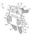
- FIG. 1is a perspective view of an anterior lumbar plate assembly according to a typical embodiment of the present invention.
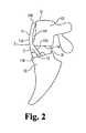
- FIG. 2is a side elevational view of the plate fixed at the L5-S1 junction of the lumbar/sacral region shown schematically.
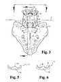
- FIG. 3is an anterior view of the plate of FIGS. 1 and 2 fixed at the L5-S1 junction.
- FIG. 4is a sectional view taken at line 4 — 4 in FIG. 3 and viewed in the direction of the arrows and showing the plate fixed to L5 and S1, S2, shown schematically and fragmentarily.
- FIG. 4Ais an enlarged fragment of FIG. 4 .
- FIG. 5is a top plan view of the anterior lumbar plate.
- FIG. 6is a bottom plan view of the plate.
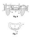
- FIG. 7is a schematic illustration of the load bearing of the plate on the ring apophysis of the sacrum.
- FIG. 8is a fragmentary sectional view through a portion of the plate 11 at line 8 — 8 in FIG. 3 and viewed in the direction of the arrows.
- the anterior lumbar plate 11is generally pear-shaped as viewed from the front in FIG. 3 to reduce contact with great vessels, but is curved in a vertical plane as shown in FIGS. 2 and 4, and is curved in a horizontal plane as shown in FIGS. 5 and 6. This facilitates fitting around the vertebra L5 and enables the anterior face 11 A (FIGS. 2 and 4) to smoothly follow the curvature of S1 and the spinal column above it.
- the upper portion 11 P of the posterior facefollows the same curves but changes at the foot portion 11 S so it can partially enter the intradiscal space between L5 and S1. It is preferable that the upper end 11 U of the plate be slightly lower than the top surface 12 of L5.
- the lower face 11 B of the foot portion 11 S of plate 11is intended to be located at or immediately above the superior plate face 13 of S1.
- the overall height between the bottom face 11 B and top edge 11 U of the plateis likely to be between 4.0 centimeters and 5.4 centimeters with an average of about 4.5 centimeters.
- the overall widthmay be about 2.8 centimeters at the narrow portion and about 4.0 centimeters at the foot portion.
- the depth (thickness) between front and rear faces of the upper portion of the plateis about 5 millimeters and increases from slot 26 down to a maximum of about 9 millimeters at the face 11 B.
- FIGS. 3 and 4there are two screw holes in the upper portion of the plate and which receive screws 16 which are screwed into L5.
- the foot portion of the platehas two recesses 17 with lower wall portions 18 curving inwardly FIG. 4 A and providing screw guide entrances to holes 19 which extend from there through the bottom face 11 B.
- Screws 20are received downward through holes 19 and screwed into and through both cortical bone at the superior end plate and cancellous bone of S1, and through cortical bone of both vertebral segments at the junction S1-S2.
- the screwsmay be 6.5 mm diameter cancellous bone screws.
- the screw hole axes 19 Aare also oriented from the screw entry surface of recesses 17 toward the longitudinal axis A of the plate which is usually substantially co-planar with the mid-plane of the spine.
- the trajectory for screws 20 and resulting angle B and the angle D (FIG. 4A) of the plane P relative to the plane of the plate bottom 11 B,are determined by the surgeon using direct visual and X-ray fluoroscopy of the sacrum. It is expected that the included angle (B) is likely to be between 10 and 30 degrees if measured in a plane P of the screw axes (FIG. 4) or a plane close to the screw axes if they are not co-planar.
- the underside of the heads of screws 20are preferably rounded above the smooth shank portions of the screws received in the holes 19 , so that the screw heads can become well seated in the curved seating surface 18 by permitting some angulation of the screws relative to the plate 11 as the screws are installed in the sacrum and tightened in place.
- Anti-backout meansare provided.
- an anti-backout screw 21(FIG. 3) is screwed into the plate and extends over the heads of the two screws 16 to prevent them from backing out of the bone L5.
- Screw 21may be of the nature shown in U.S. Pat. No. 5,364,399 to Lowery et al. Alternatives are possible.
- One exampleis an interlocking wedge feature of anti-backout screw and bone screws to prevent them from backing out. In that connection, and referring to FIG. 8, which is a section taken at line 8 — 8 in FIG.
- the particular screwsare bone screws 16 A which are anchored in the vertebral body and seat on the screw shoulders 11 S of plate 11 and anchor the plate 11 to the vertebral body L5.
- the anti-backout screw 21is threaded into the plate 11 at the inter-engaging threads 21 T.
- the angled heads of these screws as shown at 16 H for screws 16 A and 21 H for the anti-backout screw 21act as male and female Morse tapers.
- the holes in plate 11are counter-sunk at the diameter of the largest part of the head of the bone screw (i.e. at the bottom of the head).
- the set screw 21is placed in the threaded aperture between the bone screws in position to mate with the heads of the bone screws.
- the countersink bottom surface 11 Smay be at the same depth for all three screws.
- the set screw arrangementcan be used regardless of whether the screws 16 or 16 A are rigid or semi-rigid. If the geometry of the plate 11 is such that the set screw 21 seats rigidly against the heads of screw 16 , it is considered a rigid construct. If, however, a gap is left between the underneath side of the set screw 21 , and the top of the bone screws, the bone screws are semi-rigid, allowing motion superiorly and inferiorly, effectively allowing subsidence of the interbody graft. In the example of FIG. 8, the set screw 21 A is seated on the top of 11 S of the countersink (counter-bore) in the plate, and allows some gap between its Morse tapered face 21 H and the matable Morse tapered faces 16 H of the bone screws.
- This arrangement of the interlocking taper between the two bone screws and the anti-backout screwcan be expanded in a way such that the anti-backout screw is centered in an array of four bone screws.
- FIG. 7there is shown the shape 11 B of the bottom of plate 11 superimposed on the ring apophysis of the sacrum S1, demonstrating the plate 11 load-bearing on the strong ring apophysis for improved long-term fixation.
- Anti-backout screws 22are provided in the recesses 17 and positioned to prevent the screws 20 from backing out of the S1 bone.
- Other anti-backout approachesmay be used.
- Another exampleis a nickel-titanium, shape memory alloy collar arrangement as disclosed in U.S. Pat. No. 5,578,034 to Estes.
- the near-vertical orientation of the screws 20 relative to the plate face 11 B, and thereby to the superior end plate surface of S1enables screw anchorage in dense cortical bone at the sacral promontory and at the S1-S2 junction without risk of the screws entering the sacral canal SC.
- the orientation of the axes of the two screws 20 at an angle Bassists in the anti-backout or pull-out feature of this invention as it traps a wedge of cancellous bone at CS between the two screws 20 , and which is very resistant to being pulled out.
- the bottom plate face 11 B of the wedge or foot portion of the plate 11is at approximately 90 degrees (angle C) with the anterior face of the plate 11 .
- angle Cthe end plate angle C of the plate furnished for the procedure might be selected from 80 to 100 degrees.
- a plate formation assistance featureis provided.
- this slotis about 3 millimeters wide, 18 millimeters long and located about midway between the upper end 11 U and lower end 11 B of the plate.
- the locationis intended to help the surgeon appropriately bend the plate about an axis S (FIGS. 2 and 3) perpendicular to the mid-plane and located immediately below the level of the lower surface 14 of L5. This facilitates the bending deemed necessary by the surgeon to best fit the plate 11 to L5 and to S1 with the foot portion 11 S extending somewhat into the anterior portion of the disc space.
- the platecan be made taller to cover an additional one or more intervertebral junctions, with screws such as 16 installed in L4 and such higher vertebrae as are associated with the fusion junctions.
- An example of material which may be employed in the use of the inventionis a T1 6Al-4V titanium alloy according to Standard ASTM F-136. This may be associated with various types of interbody fusion device or devices and bone graft materials 31 . Examples are shown and described in U.S. Pat. No. 5,397,364 to Kozak and Boyd. Of course, the present invention may be used with other types of materials, surface finishes, and interbody fusion devices of bone dowel, push-in cage, screw-in cage, with bone graft and/or graft substitute material or other types of devices suitable for such fusion applications.
- the anterior surfaceis very smooth with rounded edges to avoid damage to the vascular and nervous systems.
Landscapes
- Health & Medical Sciences (AREA)
- Orthopedic Medicine & Surgery (AREA)
- Life Sciences & Earth Sciences (AREA)
- Surgery (AREA)
- Neurology (AREA)
- Molecular Biology (AREA)
- General Health & Medical Sciences (AREA)
- Biomedical Technology (AREA)
- Heart & Thoracic Surgery (AREA)
- Medical Informatics (AREA)
- Nuclear Medicine, Radiotherapy & Molecular Imaging (AREA)
- Animal Behavior & Ethology (AREA)
- Engineering & Computer Science (AREA)
- Public Health (AREA)
- Veterinary Medicine (AREA)
- Neurosurgery (AREA)
- Surgical Instruments (AREA)
- Prostheses (AREA)
- Polishing Bodies And Polishing Tools (AREA)
- Liquid Crystal (AREA)
Abstract
Description
1. Field of the Invention
This invention relates generally to spinal fixation systems, and more particularly to a plate to immobilize the L5 vertebra with respect to the S1 vertebra.
2. Description of Prior Art
Various types of plating devices and systems, have been used to stabilize portions of the spine. For cases in which interbody fusion is desired in the lumbar-sacral region, stabilization using plating has been preferred by many surgeons for good fixation and to avoid damage to the vascular and nervous system components adjacent the anterior surfaces of the L5 vertebra. A plating system for stabilization of the L5-S1 junction is disclosed in U.S. Pat. No. 5,127,912 issued Jul. 7, 1992 to Ray and Ashman. It is a posterior system. While posterior fixation systems are often used in anterior/posterior fusions, the anterior surgical approach to the fusion is preferred from several perspectives. Less blood loss and reduced post-operative pain can be achieved. Also, effective anterior plating could avoid the additional posterior surgery necessary in the past to provide the additional stabilization needed to establish a reasonable fusion rate.
U.S. Pat. No. 6,045,552 issued Apr. 4, 2000 to Zucherman and Hsu discloses a plate for immobilizing the L5 vertebra with respect to the S1 vertebra. Earlier patents and publications are cited in that patent. Also, it is understood that Kostuick and Yuan had modified anterio-lateral plates, for example (e.g., the Syracuse I Plate) for use on the anterior lumbar spine. Also, it is understood that earlier literature reported clinical experience (Humphries and Hawk 1951, 1961) with an anterior lumbar plate manufactured by Austenal Company, New York. There remains a need for additional stability to an anterior lumbar interbody fusion using the same anterior surgical site for plating.
Described briefly according to the illustrated embodiment of the invention, a plate is provided having curvature in two planes such that it conforms to the curvature of the L5 vertebral body and the patient's lordotic curve. Holes are provided receiving screws for anchorage in the vertebral body and sacrum. The screws and receiver holes in an upper portion of the plate are generally perpendicular to that portion of the plate. A lower portion of the plate is formed with a flange or foot portion which provides a wider base end area for support on the upper face of S1 in the L5-S1 interspace. The foot portion is also arranged for appropriate entry angle of screws into the sacrum such as to improve anchorage in the sacrum. The screws and receiver holes in the lower portion of the plate are through the front and bottom walls of the lower portion of the plate and at a steep angle relative to the front of the plate and engaged with the cortical bone of the sacrum at the superior end plate and at the S1-S2 junction. The foot portion also incorporates anti-backout and low profile features. The anterior lumbar plate is situated to maintain the anterior interbody bone graft in compression by resisting tensile forces during extension. The plate can also be extended to the L4-L5 junction by increasing the length of the plate and inclusion of holes in the upper portion for anchoring to L4.
FIG. 1 is a perspective view of an anterior lumbar plate assembly according to a typical embodiment of the present invention.
FIG. 2 is a side elevational view of the plate fixed at the L5-S1 junction of the lumbar/sacral region shown schematically.
FIG. 3 is an anterior view of the plate of FIGS. 1 and 2 fixed at the L5-S1 junction.
FIG. 4 is a sectional view taken at line4—4 in FIG.3 and viewed in the direction of the arrows and showing the plate fixed to L5 and S1, S2, shown schematically and fragmentarily.
FIG. 4A is an enlarged fragment of FIG.4.
FIG. 5 is a top plan view of the anterior lumbar plate.
FIG. 6 is a bottom plan view of the plate.
FIG. 7 is a schematic illustration of the load bearing of the plate on the ring apophysis of the sacrum.
FIG. 8 is a fragmentary sectional view through a portion of theplate 11 atline 8—8 in FIG.3 and viewed in the direction of the arrows.
For the purposes of promoting an understanding of the principles of the invention, reference will now be made to the embodiment illustrated in the drawings and specific language will be used to describe the same. It will nevertheless be understood that no limitation of the scope of the invention is thereby intended, such alterations and further modifications in the illustrated device, and such further applications of the principles of the invention as illustrated therein being contemplated as would normally occur to one skilled in the art to which the invention relates.
Theanterior lumbar plate 11 according to the illustrated embodiment of the invention is generally pear-shaped as viewed from the front in FIG. 3 to reduce contact with great vessels, but is curved in a vertical plane as shown in FIGS. 2 and 4, and is curved in a horizontal plane as shown in FIGS. 5 and 6. This facilitates fitting around the vertebra L5 and enables theanterior face 11A (FIGS. 2 and 4) to smoothly follow the curvature of S1 and the spinal column above it. Theupper portion 11P of the posterior face follows the same curves but changes at thefoot portion 11S so it can partially enter the intradiscal space between L5 and S1. It is preferable that the upper end11U of the plate be slightly lower than thetop surface 12 of L5. Thelower face 11B of thefoot portion 11S ofplate 11 is intended to be located at or immediately above thesuperior plate face 13 of S1.
Depending upon the anatomy of the patient, the overall height between thebottom face 11B and top edge11U of the plate is likely to be between 4.0 centimeters and 5.4 centimeters with an average of about 4.5 centimeters. The overall width may be about 2.8 centimeters at the narrow portion and about 4.0 centimeters at the foot portion. The depth (thickness) between front and rear faces of the upper portion of the plate is about 5 millimeters and increases fromslot 26 down to a maximum of about 9 millimeters at theface 11B. As mentioned above, if it is desired to extend the plate to stabilize two levels, that can be simply done by increasing the overall height between thebottom face 11B of the plate and the top edge of the plate and adding screw holes of the type discussed below to anchor into the L4 vertebra.
As shown in FIGS. 3 and 4, there are two screw holes in the upper portion of the plate and which receivescrews 16 which are screwed into L5. The foot portion of the plate has tworecesses 17 withlower wall portions 18 curving inwardly FIG.4A and providing screw guide entrances toholes 19 which extend from there through thebottom face 11B.Screws 20 are received downward throughholes 19 and screwed into and through both cortical bone at the superior end plate and cancellous bone of S1, and through cortical bone of both vertebral segments at the junction S1-S2. As an example, the screws may be 6.5 mm diameter cancellous bone screws. Thescrew hole axes 19A are also oriented from the screw entry surface ofrecesses 17 toward the longitudinal axis A of the plate which is usually substantially co-planar with the mid-plane of the spine. The trajectory forscrews 20 and resulting angle B and the angle D (FIG. 4A) of the plane P relative to the plane of theplate bottom 11B, are determined by the surgeon using direct visual and X-ray fluoroscopy of the sacrum. It is expected that the included angle (B) is likely to be between 10 and 30 degrees if measured in a plane P of the screw axes (FIG. 4) or a plane close to the screw axes if they are not co-planar. The underside of the heads ofscrews 20 are preferably rounded above the smooth shank portions of the screws received in theholes 19, so that the screw heads can become well seated in thecurved seating surface 18 by permitting some angulation of the screws relative to theplate 11 as the screws are installed in the sacrum and tightened in place.
Anti-backout means are provided. In the illustrated example, an anti-backout screw21 (FIG. 3) is screwed into the plate and extends over the heads of the twoscrews 16 to prevent them from backing out of the bone L5.Screw 21 may be of the nature shown in U.S. Pat. No. 5,364,399 to Lowery et al. Alternatives are possible. One example is an interlocking wedge feature of anti-backout screw and bone screws to prevent them from backing out. In that connection, and referring to FIG. 8, which is a section taken atline 8—8 in FIG.3 and viewed in the direction of the arrows, in this instance, the particular screws arebone screws 16A which are anchored in the vertebral body and seat on the screw shoulders11S ofplate 11 and anchor theplate 11 to the vertebral body L5. Theanti-backout screw 21 is threaded into theplate 11 at theinter-engaging threads 21T. The angled heads of these screws as shown at16H forscrews anti-backout screw 21, act as male and female Morse tapers. The holes inplate 11 are counter-sunk at the diameter of the largest part of the head of the bone screw (i.e. at the bottom of the head). Theset screw 21 is placed in the threaded aperture between the bone screws in position to mate with the heads of the bone screws. Thecountersink bottom surface 11S may be at the same depth for all three screws.
The set screw arrangement can be used regardless of whether thescrews plate 11 is such that theset screw 21 seats rigidly against the heads ofscrew 16, it is considered a rigid construct. If, however, a gap is left between the underneath side of theset screw 21, and the top of the bone screws, the bone screws are semi-rigid, allowing motion superiorly and inferiorly, effectively allowing subsidence of the interbody graft. In the example of FIG. 8, theset screw 21A is seated on the top of11S of the countersink (counter-bore) in the plate, and allows some gap between its Morse taperedface 21H and the matable Morse tapered faces16H of the bone screws. But in the event of any tendency of the bone screw to back out, the wedging between those surfaces will take place and terminate any back-out. This arrangement of the interlocking taper between the two bone screws and the anti-backout screw can be expanded in a way such that the anti-backout screw is centered in an array of four bone screws.
Referring now to FIG. 7, there is shown theshape 11B of the bottom ofplate 11 superimposed on the ring apophysis of the sacrum S1, demonstrating theplate 11 load-bearing on the strong ring apophysis for improved long-term fixation.
As shown in FIGS. 2 and 4, thebottom plate face 11B of the wedge or foot portion of theplate 11 is at approximately 90 degrees (angle C) with the anterior face of theplate 11. Depending upon the normal angle between the superior end plate of S1 and the inferior end plate surface of L5 as well as can be determined for a patient, the end plate angle C of the plate furnished for the procedure might be selected from 80 to 100 degrees.
In addition to appropriately choosing a size of plate to fit the patient, a plate formation assistance feature is provided. In the illustrated embodiment of the plate, this is aslot 26. This slot is about 3 millimeters wide, 18 millimeters long and located about midway between the upper end11U andlower end 11B of the plate. The location is intended to help the surgeon appropriately bend the plate about an axis S (FIGS. 2 and 3) perpendicular to the mid-plane and located immediately below the level of thelower surface 14 of L5. This facilitates the bending deemed necessary by the surgeon to best fit theplate 11 to L5 and to S1 with thefoot portion 11S extending somewhat into the anterior portion of the disc space. This is to avoid necessitating resection of some of the lower anterior portion of L5 to receive theupper portion 11A of the plate as could occur if the bend were too low and, if the bend were too high, having the anterior surface of the plate at the bend projecting too far out in the anterior direction with attendant risk of impingement of the vasculature structures and sympathetic nerve bundle.
As it is possible to encounter in different patients, a range of space between thesuperior plate surface 13 of S1 andinferior plate surface 14 of L5, anywhere from 12 to 18 or so millimeters at the anterior edges, it can be desirable to provide a selection of several sizes of plates and locations of the relief slots, to provide the optimum choices for the spinal surgeon. As mentioned above, if it is desirable to provide fusion at more than just the one vertebral space described, the plate can be made taller to cover an additional one or more intervertebral junctions, with screws such as16 installed in L4 and such higher vertebrae as are associated with the fusion junctions.
An example of material which may be employed in the use of the invention is a T1 6Al-4V titanium alloy according to Standard ASTM F-136. This may be associated with various types of interbody fusion device or devices andbone graft materials 31. Examples are shown and described in U.S. Pat. No. 5,397,364 to Kozak and Boyd. Of course, the present invention may be used with other types of materials, surface finishes, and interbody fusion devices of bone dowel, push-in cage, screw-in cage, with bone graft and/or graft substitute material or other types of devices suitable for such fusion applications. The anterior surface is very smooth with rounded edges to avoid damage to the vascular and nervous systems.
While the invention has been illustrated and described in detail in the drawings and foregoing description, the same is to be considered as illustrative and not restrictive in character, it being understood that only the preferred embodiment has been shown and described and that all changes and modifications that come within the spirit of the invention are desired to be protected.
Claims (13)
1. A stabilizer for lumbar/sacral junction and comprising:
a plate having a front wall and a foot portion projecting rearwardly from a lower portion of the wall and having a caudally-directed bottom surface;
two upper holes in the wall to receive screws for passage into an L5 vertebra; and
two lower holes in the wall and extending through the bottom surface of the plate to receive screws for passage through said foot portion into the sacrum.
2. The stabilizer ofclaim 1 and wherein:
said plate has front wall recesses, one for each of said lower holes and providing seating surfaces for heads of screws when received in said lower holes.
3. The stabilizer ofclaim 2 and wherein:
said seating surfaces are inclined inwardly whereby screw heads when received thereon are self-centering.
4. The stabilizer ofclaim 3 and wherein:
said inwardly inclined surfaces are curved downwardly toward entrance ends of said lower holes.
5. The stabilizer ofclaim 3 and wherein:
said lower holes have axes which converge as they extend below the bottom of the plate.
6. The stabilizer ofclaim 5 and wherein:
said axes lie in a plane generally parallel to the lower portion of the front wall.
7. A stabilizer for the lumbar/sacral joint of a higher vertebrate and comprising:
a plate having an upper portion and a foot portion,
the upper portion being curved in a horizontal plane for fitting to an L5 vertebra and the foot portion being shaped to reside in anterior inter-vertebral space between L5 and S1 and to be fittingly received and rest on the sacrum superior end plate;
at least one fastener through the upper portion and generally perpendicular to the upper portion for anchorage to L5;
a second fastener through the foot portion at an angle for reception and extension in cortical bone of the sacrum at the sacral promontory, and for engagement in cortical bone at the S1-S2 junction.
8. The stabilizer ofclaim 7 and further comprising:
third and fourth fasteners, said third fastener extending through the upper portion and generally perpendicular to the upper portion;
said fourth fastener extending through said foot portion at an angle for reception and extension in cortical bone of the sacrum at the sacral promontory and for engagement in cortical bone at the S1-S2 junction.
9. The stabilizer ofclaim 8 and wherein:
said second and fourth fasteners are elongate and have longitudinal axes and are oriented with their axes converging from their respective points of departure downward from a bottom surface of said foot portion.
10. The stabilizer ofclaim 7 and wherein:
said foot portion has a front wall and a bottom wall; and
said foot portion has an aperture therethrough having a fastener entrance through said front wall and a fastener exit through said bottom wall.
11. The stabilizer ofclaim 10 and wherein:
said aperture has a portion intermediate said entrance and exit, and a curved, fastener-head seating surface converging from said front wall to said intermediate portion.
12. The stabilizer ofclaim 10 and wherein:
said plate is made of a biocompatible alloy, and said foot portion thereof is adapted to load bearing on ring apophysis of the sacrum, the upper portion and foot portion being shaped in an anterior aspect to minimize contact with great circulatory vessels in the region of L5-S1.
13. The stabilizer ofclaim 1 wherein said lower holes have axes which converge as they extend below the bottom of the plate.
Priority Applications (13)
| Application Number | Priority Date | Filing Date | Title |
|---|---|---|---|
| US09/696,130US6740088B1 (en) | 2000-10-25 | 2000-10-25 | Anterior lumbar plate and method |
| DE60134257TDE60134257D1 (en) | 2000-10-25 | 2001-10-24 | FRONT LUMBAR PLATE |
| CA002426119ACA2426119A1 (en) | 2000-10-25 | 2001-10-24 | Anterior lumbar plate and method |
| EP07010905AEP1835185A2 (en) | 2000-10-25 | 2001-10-24 | An anti-backout system for screws |
| JP2002558910AJP2004517685A (en) | 2000-10-25 | 2001-10-24 | Lumbar anterior plate and method |
| AT01998073TATE396654T1 (en) | 2000-10-25 | 2001-10-24 | ANTERIOR LUMBAR PLATE |
| EP01998073AEP1335676B1 (en) | 2000-10-25 | 2001-10-24 | Anterior lumbar plate |
| AU2002249832AAU2002249832B2 (en) | 2000-10-25 | 2001-10-24 | Anterior lumbar plate and method |
| PCT/US2001/049610WO2002058574A2 (en) | 2000-10-25 | 2001-10-24 | Anterior lumbar plate and method |
| EP07010904AEP1852077B1 (en) | 2000-10-25 | 2001-10-24 | Stabilizer |
| US10/755,583US7060069B2 (en) | 2000-10-25 | 2004-01-12 | Anterior lumbar plate and method |
| US10/843,110US8016863B2 (en) | 2000-10-25 | 2004-05-11 | Anterior lumbar plate and method |
| US13/204,195US8617224B2 (en) | 2000-10-25 | 2011-08-05 | Anterior lumbar plate and method |
Applications Claiming Priority (1)
| Application Number | Priority Date | Filing Date | Title |
|---|---|---|---|
| US09/696,130US6740088B1 (en) | 2000-10-25 | 2000-10-25 | Anterior lumbar plate and method |
Related Child Applications (2)
| Application Number | Title | Priority Date | Filing Date |
|---|---|---|---|
| US10/755,583DivisionUS7060069B2 (en) | 2000-10-25 | 2004-01-12 | Anterior lumbar plate and method |
| US10/843,110ContinuationUS8016863B2 (en) | 2000-10-25 | 2004-05-11 | Anterior lumbar plate and method |
Publications (1)
| Publication Number | Publication Date |
|---|---|
| US6740088B1true US6740088B1 (en) | 2004-05-25 |
Family
ID=24795830
Family Applications (4)
| Application Number | Title | Priority Date | Filing Date |
|---|---|---|---|
| US09/696,130Expired - LifetimeUS6740088B1 (en) | 2000-10-25 | 2000-10-25 | Anterior lumbar plate and method |
| US10/755,583Expired - LifetimeUS7060069B2 (en) | 2000-10-25 | 2004-01-12 | Anterior lumbar plate and method |
| US10/843,110Expired - Fee RelatedUS8016863B2 (en) | 2000-10-25 | 2004-05-11 | Anterior lumbar plate and method |
| US13/204,195Expired - Fee RelatedUS8617224B2 (en) | 2000-10-25 | 2011-08-05 | Anterior lumbar plate and method |
Family Applications After (3)
| Application Number | Title | Priority Date | Filing Date |
|---|---|---|---|
| US10/755,583Expired - LifetimeUS7060069B2 (en) | 2000-10-25 | 2004-01-12 | Anterior lumbar plate and method |
| US10/843,110Expired - Fee RelatedUS8016863B2 (en) | 2000-10-25 | 2004-05-11 | Anterior lumbar plate and method |
| US13/204,195Expired - Fee RelatedUS8617224B2 (en) | 2000-10-25 | 2011-08-05 | Anterior lumbar plate and method |
Country Status (8)
| Country | Link |
|---|---|
| US (4) | US6740088B1 (en) |
| EP (3) | EP1335676B1 (en) |
| JP (1) | JP2004517685A (en) |
| AT (1) | ATE396654T1 (en) |
| AU (1) | AU2002249832B2 (en) |
| CA (1) | CA2426119A1 (en) |
| DE (1) | DE60134257D1 (en) |
| WO (1) | WO2002058574A2 (en) |
Cited By (44)
| Publication number | Priority date | Publication date | Assignee | Title |
|---|---|---|---|---|
| US20040111089A1 (en)* | 2002-12-04 | 2004-06-10 | Stevens Peter M. | Bone alignment implant and method of use |
| US20040193269A1 (en)* | 2003-03-31 | 2004-09-30 | Depuy Acromed, Inc. | Anterior lumbar interbody fusion cage with locking plate |
| US20040210221A1 (en)* | 2000-10-25 | 2004-10-21 | Jeffrey Kozak | Anterior lumbar plate and method |
| US20050085913A1 (en)* | 2003-03-31 | 2005-04-21 | Robert Fraser | Spinal fixation plate |
| US20050187553A1 (en)* | 2001-08-24 | 2005-08-25 | Grabowski John J. | Bone fixation device |
| US20060033893A1 (en)* | 2003-11-04 | 2006-02-16 | Canon Kabushiki Kaisha | Exposure technique |
| US20060036249A1 (en)* | 2004-08-12 | 2006-02-16 | Baynham Bret O | Bone plate with screw lock |
| US20060074490A1 (en)* | 2004-10-01 | 2006-04-06 | Sweeney Patrick J | Vertebral prosthesis and spinal fixation system |
| US20060149253A1 (en)* | 2005-01-06 | 2006-07-06 | Doubler Robert L | Spinal plate with internal screw locks |
| US20060149255A1 (en)* | 2005-01-06 | 2006-07-06 | Doubler Robert L | Spinal implant kit |
| US20060149239A1 (en)* | 2004-12-13 | 2006-07-06 | St. Francis Medical Technologies, Inc. | Inter-cervical facet implant with locking screw and method |
| US20060242813A1 (en)* | 2005-04-29 | 2006-11-02 | Fred Molz | Metal injection molding of spinal fixation systems components |
| US20080091206A1 (en)* | 2006-10-13 | 2008-04-17 | Jeffrey Johnson | Bone Plate |
| US20080269806A1 (en)* | 2007-04-24 | 2008-10-30 | Jeffrey Zhang | Prostheses for locking an artificial disc in an intervertebral disc space |
| US20080306550A1 (en)* | 2007-06-07 | 2008-12-11 | Matityahu Amir M | Spine repair assembly |
| US20080312699A1 (en)* | 2007-04-11 | 2008-12-18 | Jeffrey Johnson | Recessed plate system |
| US7468069B2 (en) | 2004-02-10 | 2008-12-23 | Atlas Spine, Inc. | Static anterior cervical plate |
| USD592946S1 (en) | 2007-07-25 | 2009-05-26 | Spinal U.S.A. | Locking rivet head |
| US20090177239A1 (en)* | 2007-08-06 | 2009-07-09 | Michael Castro | Cervical plate instrument kit |
| US20090265007A1 (en)* | 2007-11-12 | 2009-10-22 | Dennis Colleran | Vertebral interbody compression implant |
| US20090270927A1 (en)* | 2008-04-25 | 2009-10-29 | Pioneer Surgical Technology, Inc. | Bone Plate System |
| US20090287256A1 (en)* | 2008-05-15 | 2009-11-19 | Loyola Walter X | Vertebral fixation plate and screw assembly |
| US20100042159A1 (en)* | 2008-07-17 | 2010-02-18 | Alphatec Spine, Inc. | Bone plate assembly |
| US20100137916A1 (en)* | 2008-12-03 | 2010-06-03 | Warsaw Orthopedic, Inc., An Indiana Corporation | Spinal plates for stabilizing segments |
| US7758616B2 (en) | 2001-04-06 | 2010-07-20 | Warsaw Orthopedic, Inc. | Anterior plating system and method |
| US20110071570A1 (en)* | 2009-09-24 | 2011-03-24 | Warsaw Orthopedic, Inc. | Composite vertebral rod system and methods of use |
| US20110218533A1 (en)* | 2010-03-08 | 2011-09-08 | Bernard Prandi | Radius-plate assembly |
| US20110218534A1 (en)* | 2010-03-08 | 2011-09-08 | Bernard Prandi | Adjustable-angle radius plate |
| US20110218574A1 (en)* | 2010-03-03 | 2011-09-08 | Warsaw Orthopedic, Inc. | Dynamic vertebral construct |
| US8142508B1 (en) | 2007-07-02 | 2012-03-27 | Theken Spine, Llc | Spinal cage having deployable member which is removable |
| US8157842B2 (en) | 2009-06-12 | 2012-04-17 | Kyphon Sarl | Interspinous implant and methods of use |
| US8292958B1 (en) | 2007-07-02 | 2012-10-23 | Theken Spine, Llc | Spinal cage having deployable member |
| US20130006309A1 (en)* | 2011-06-30 | 2013-01-03 | Morgan Packard Lorio | Spinal plate and method for using same |
| US8545562B1 (en) | 2007-07-02 | 2013-10-01 | Theken Spine, Llc | Deployable member for use with an intervertebral cage |
| US8814912B2 (en) | 2012-07-27 | 2014-08-26 | Zimmer Spine, Inc. | Bone stabilization member with bone screw retention mechanism |
| US8864829B1 (en) | 2007-07-02 | 2014-10-21 | Theken Spine, Llc | Spinal cage having deployable member |
| US9198769B2 (en) | 2011-12-23 | 2015-12-01 | Pioneer Surgical Technology, Inc. | Bone anchor assembly, bone plate system, and method |
| US9277946B2 (en) | 2011-09-06 | 2016-03-08 | Amendia, Inc. | Spinal fusion system |
| US20160074070A1 (en)* | 2014-09-12 | 2016-03-17 | Empire Technology Development Llc | Meniscal repositioning device |
| USD779065S1 (en) | 2014-10-08 | 2017-02-14 | Nuvasive, Inc. | Anterior cervical bone plate |
| US9918750B2 (en)* | 2016-08-04 | 2018-03-20 | Osseus Fusion Systems, Llc | Method, system, and apparatus for temporary anterior cervical plate fixation |
| US10143499B2 (en) | 2013-10-09 | 2018-12-04 | Stryker European Holdings I, Llc | Pivoting vertebral plate |
| US10342674B2 (en) | 2007-07-02 | 2019-07-09 | Theken Spine, Llc | Spinal cage having deployable member |
| US12186201B2 (en) | 2007-07-02 | 2025-01-07 | Theken Spine, Llc | Spinal cage having deployable member |
Families Citing this family (95)
| Publication number | Priority date | Publication date | Assignee | Title |
|---|---|---|---|---|
| US7250054B2 (en) | 2002-08-28 | 2007-07-31 | Smith & Nephew, Inc. | Systems, methods, and apparatuses for clamping and reclamping an orthopedic surgical cable |
| US7179260B2 (en) | 2003-09-29 | 2007-02-20 | Smith & Nephew, Inc. | Bone plates and bone plate assemblies |
| US8105367B2 (en) | 2003-09-29 | 2012-01-31 | Smith & Nephew, Inc. | Bone plate and bone plate assemblies including polyaxial fasteners |
| US8388667B2 (en) | 2004-08-09 | 2013-03-05 | Si-Bone, Inc. | Systems and methods for the fixation or fusion of bone using compressive implants |
| US20180228621A1 (en) | 2004-08-09 | 2018-08-16 | Mark A. Reiley | Apparatus, systems, and methods for the fixation or fusion of bone |
| US8414648B2 (en) | 2004-08-09 | 2013-04-09 | Si-Bone Inc. | Apparatus, systems, and methods for achieving trans-iliac lumbar fusion |
| US8470004B2 (en)* | 2004-08-09 | 2013-06-25 | Si-Bone Inc. | Apparatus, systems, and methods for stabilizing a spondylolisthesis |
| US20070156241A1 (en) | 2004-08-09 | 2007-07-05 | Reiley Mark A | Systems and methods for the fixation or fusion of bone |
| US8425570B2 (en) | 2004-08-09 | 2013-04-23 | Si-Bone Inc. | Apparatus, systems, and methods for achieving anterior lumbar interbody fusion |
| US20060036251A1 (en) | 2004-08-09 | 2006-02-16 | Reiley Mark A | Systems and methods for the fixation or fusion of bone |
| US8444693B2 (en) | 2004-08-09 | 2013-05-21 | Si-Bone Inc. | Apparatus, systems, and methods for achieving lumbar facet fusion |
| US9662158B2 (en) | 2004-08-09 | 2017-05-30 | Si-Bone Inc. | Systems and methods for the fixation or fusion of bone at or near a sacroiliac joint |
| US9949843B2 (en) | 2004-08-09 | 2018-04-24 | Si-Bone Inc. | Apparatus, systems, and methods for the fixation or fusion of bone |
| US8469966B2 (en) | 2004-09-23 | 2013-06-25 | Smith & Nephew, Inc. | Systems, methods, and apparatuses for tensioning an orthopedic surgical cable |
| US8394130B2 (en) | 2005-03-17 | 2013-03-12 | Biomet C.V. | Modular fracture fixation system |
| US8062296B2 (en)* | 2005-03-17 | 2011-11-22 | Depuy Products, Inc. | Modular fracture fixation plate system with multiple metaphyseal and diaphyseal plates |
| US7621942B2 (en)* | 2005-03-21 | 2009-11-24 | Zimmer Spine, Inc. | Variable geometry occipital fixation plate |
| CA2616798C (en) | 2005-07-25 | 2014-01-28 | Smith & Nephew, Inc. | Systems and methods for using polyaxial plates |
| US8382807B2 (en) | 2005-07-25 | 2013-02-26 | Smith & Nephew, Inc. | Systems and methods for using polyaxial plates |
| US20070233108A1 (en)* | 2006-03-15 | 2007-10-04 | Stalcup Gregory C | Spine fixation device |
| US20070299441A1 (en)* | 2006-06-09 | 2007-12-27 | Zachary M. Hoffman | Adjustable Occipital Plate |
| US7901433B2 (en) | 2006-10-04 | 2011-03-08 | Zimmer Spine, Inc. | Occipito-cervical stabilization system and method |
| US8262710B2 (en)* | 2006-10-24 | 2012-09-11 | Aesculap Implant Systems, Llc | Dynamic stabilization device for anterior lower lumbar vertebral fusion |
| US8147527B2 (en) | 2006-11-28 | 2012-04-03 | Zimmer Spine, Inc. | Adjustable occipital plate |
| US8636737B2 (en)* | 2006-12-27 | 2014-01-28 | Zimmer Spine, Inc. | Modular occipital plate |
| US8246662B2 (en)* | 2006-12-27 | 2012-08-21 | Zimmer Spine, Inc. | Modular occipital plate |
| US8636783B2 (en) | 2006-12-29 | 2014-01-28 | Zimmer Spine, Inc. | Spinal stabilization systems and methods |
| US8034081B2 (en) | 2007-02-06 | 2011-10-11 | CollabComl, LLC | Interspinous dynamic stabilization implant and method of implanting |
| US7918853B2 (en) | 2007-03-20 | 2011-04-05 | Smith & Nephew, Inc. | Orthopaedic plate and screw assembly |
| US20090043341A1 (en)* | 2007-08-09 | 2009-02-12 | Aesculap, Inc. | Dynamic extension plate for anterior cervical fusion and method of installation |
| US8623062B2 (en) | 2008-09-29 | 2014-01-07 | Dimitriy G. Kondrashov | System and method to stablize a spinal column including a spinolaminar locking plate |
| US8795340B2 (en)* | 2008-11-07 | 2014-08-05 | Globus Medical, Inc. | Vertical inline plate |
| US8709053B2 (en)* | 2009-04-30 | 2014-04-29 | Sean Suh | Orthopedic fastener blocking system |
| US8372117B2 (en) | 2009-06-05 | 2013-02-12 | Kyphon Sarl | Multi-level interspinous implants and methods of use |
| US8834469B2 (en) | 2009-06-30 | 2014-09-16 | Smith & Nephew, Inc. | Orthopaedic implant and fastener assembly |
| FR2971139B1 (en)* | 2011-02-03 | 2013-02-15 | Medicrea Int | PLATE FOR THE OSTEOSYNTHESIS OF THE LOMBO-SACRED JOINT |
| US9005255B2 (en) | 2011-02-15 | 2015-04-14 | Orthohelix Surgical Designs, Inc. | Orthopedic compression plate |
| AU2012271441B2 (en) | 2011-06-15 | 2017-02-02 | Smith & Nephew, Inc. | Variable angle locking implant |
| EP2725999B1 (en) | 2011-06-29 | 2019-04-10 | Nextremity Solutions, Inc. | Bone plate hybrid device |
| EP2774222B1 (en)* | 2011-11-02 | 2020-01-22 | Earl A. Lirette III | Terminal device for grounding direct current electrical component |
| US9060822B2 (en) | 2011-12-28 | 2015-06-23 | Orthohelix Surgical Designs, Inc. | Orthopedic compression plate and method of surgery |
| US9044321B2 (en) | 2012-03-09 | 2015-06-02 | Si-Bone Inc. | Integrated implant |
| US10363140B2 (en) | 2012-03-09 | 2019-07-30 | Si-Bone Inc. | Systems, device, and methods for joint fusion |
| EP3818947B1 (en) | 2012-05-04 | 2023-08-30 | SI-Bone, Inc. | Fenestrated implant |
| US20150238233A1 (en)* | 2012-08-09 | 2015-08-27 | Trinity Orthopedics, Llc | Intervertebral Plate Systems and Methods of Use |
| US9907588B2 (en) | 2012-09-06 | 2018-03-06 | Orthohelix Surgical Designs, Inc. | Orthopedic dual pocket compression plate and method of surgery |
| WO2014145902A1 (en) | 2013-03-15 | 2014-09-18 | Si-Bone Inc. | Implants for spinal fixation or fusion |
| US9839448B2 (en) | 2013-10-15 | 2017-12-12 | Si-Bone Inc. | Implant placement |
| US11147688B2 (en) | 2013-10-15 | 2021-10-19 | Si-Bone Inc. | Implant placement |
| JP6542362B2 (en) | 2014-09-18 | 2019-07-10 | エスアイ−ボーン・インコーポレイテッドSi−Bone, Inc. | Matrix implant |
| US10166033B2 (en) | 2014-09-18 | 2019-01-01 | Si-Bone Inc. | Implants for bone fixation or fusion |
| US10376206B2 (en) | 2015-04-01 | 2019-08-13 | Si-Bone Inc. | Neuromonitoring systems and methods for bone fixation or fusion procedures |
| US10687874B2 (en) | 2015-08-27 | 2020-06-23 | Globus Medical, Inc | Proximal humeral stabilization system |
| US11076898B2 (en) | 2015-08-27 | 2021-08-03 | Globus Medical, Inc. | Proximal humeral stabilization system |
| US11197682B2 (en) | 2015-08-27 | 2021-12-14 | Globus Medical, Inc. | Proximal humeral stabilization system |
| GB2557840B (en) | 2015-09-18 | 2021-07-21 | Smith & Nephew Inc | Bone plate |
| US10130402B2 (en) | 2015-09-25 | 2018-11-20 | Globus Medical, Inc. | Bone fixation devices having a locking feature |
| US9974581B2 (en) | 2015-11-20 | 2018-05-22 | Globus Medical, Inc. | Expandable intramedullary systems and methods of using the same |
| US9795411B2 (en) | 2016-03-02 | 2017-10-24 | Globus Medical, Inc. | Fixators for bone stabilization and associated systems and methods |
| US10531905B2 (en) | 2016-04-19 | 2020-01-14 | Globus Medical, Inc. | Implantable compression screws |
| US11331128B2 (en) | 2016-08-17 | 2022-05-17 | Globus Medical Inc. | Distal radius stabilization system |
| US10420596B2 (en) | 2016-08-17 | 2019-09-24 | Globus Medical, Inc. | Volar distal radius stabilization system |
| US11197701B2 (en) | 2016-08-17 | 2021-12-14 | Globus Medical, Inc. | Stabilization systems |
| US11213327B2 (en) | 2016-08-17 | 2022-01-04 | Globus Medical, Inc. | Fracture plates, systems, and methods |
| US11141204B2 (en) | 2016-08-17 | 2021-10-12 | Globus Medical Inc. | Wrist stabilization systems |
| US10687873B2 (en) | 2016-08-17 | 2020-06-23 | Globus Medical Inc. | Stabilization systems |
| US10383668B2 (en) | 2016-08-17 | 2019-08-20 | Globus Medical, Inc. | Volar distal radius stabilization system |
| US10751098B2 (en) | 2016-08-17 | 2020-08-25 | Globus Medical Inc. | Stabilization systems |
| US11432857B2 (en) | 2016-08-17 | 2022-09-06 | Globus Medical, Inc. | Stabilization systems |
| US10575884B2 (en) | 2016-08-17 | 2020-03-03 | Globus Medical, Inc. | Fracture plates, systems, and methods |
| US10299847B2 (en) | 2016-09-22 | 2019-05-28 | Globus Medical, Inc. | Systems and methods for intramedullary nail implantation |
| US10881438B2 (en) | 2017-03-10 | 2021-01-05 | Globus Medical, Inc. | Clavicle fixation system |
| US10905477B2 (en) | 2017-03-13 | 2021-02-02 | Globus Medical, Inc. | Bone stabilization systems |
| US10368928B2 (en) | 2017-03-13 | 2019-08-06 | Globus Medical, Inc. | Bone stabilization systems |
| US10856920B2 (en) | 2017-09-13 | 2020-12-08 | Globus Medical Inc. | Bone stabilization systems |
| US12318122B2 (en) | 2017-09-13 | 2025-06-03 | Globus Medical, Inc. | Bone stabilization systems |
| US11096730B2 (en) | 2017-09-13 | 2021-08-24 | Globus Medical Inc. | Bone stabilization systems |
| US11116519B2 (en) | 2017-09-26 | 2021-09-14 | Si-Bone Inc. | Systems and methods for decorticating the sacroiliac joint |
| US11071570B2 (en) | 2018-03-02 | 2021-07-27 | Globus Medical, Inc. | Distal tibial plating system |
| US11224468B2 (en) | 2018-03-02 | 2022-01-18 | Globus Medical, Inc. | Distal tibial plating system |
| ES3011907T3 (en) | 2018-03-28 | 2025-04-08 | Si Bone Inc | Threaded implants for use across bone segments |
| US11141172B2 (en) | 2018-04-11 | 2021-10-12 | Globus Medical, Inc. | Method and apparatus for locking a drill guide in a polyaxial hole |
| US11202663B2 (en) | 2019-02-13 | 2021-12-21 | Globus Medical, Inc. | Proximal humeral stabilization systems and methods thereof |
| EP4613244A2 (en) | 2019-02-14 | 2025-09-10 | SI-Bone Inc. | Implants for spinal fixation and or fusion |
| US11369419B2 (en) | 2019-02-14 | 2022-06-28 | Si-Bone Inc. | Implants for spinal fixation and or fusion |
| US12185995B2 (en) | 2019-10-09 | 2025-01-07 | Globus Medical, Inc. | Bone stabilization systems |
| US11129627B2 (en) | 2019-10-30 | 2021-09-28 | Globus Medical, Inc. | Method and apparatus for inserting a bone plate |
| JP7646654B2 (en) | 2019-11-21 | 2025-03-17 | エスアイ-ボーン・インコーポレイテッド | Rod coupling assembly for bone stabilization construct - Patent application |
| AU2020392121B2 (en) | 2019-11-27 | 2025-05-22 | Si-Bone, Inc. | Bone stabilizing implants and methods of placement across SI joints |
| EP4072452A4 (en) | 2019-12-09 | 2023-12-20 | SI-Bone, Inc. | Sacro-iliac joint stabilizing implants and methods of implantation |
| US11723647B2 (en) | 2019-12-17 | 2023-08-15 | Globus Medical, Inc. | Syndesmosis fixation assembly |
| US11253305B2 (en) | 2020-04-08 | 2022-02-22 | DePuy Synthes Products, Inc. | Suprapectineal quadrilateral bone plating system and methods of making and using same |
| EP4259015A4 (en) | 2020-12-09 | 2024-09-11 | SI-Bone, Inc. | SACROILIAC JOINT STABILIZATION IMPLANTS AND METHODS OF IMPLANTATION |
| US12064150B2 (en) | 2022-01-19 | 2024-08-20 | Globus Medical Inc. | System and method for treating bone fractures |
| WO2025038769A1 (en) | 2023-08-15 | 2025-02-20 | Si-Bone Inc. | Pelvic stabilization implants, methods of use and manufacture |
Citations (28)
| Publication number | Priority date | Publication date | Assignee | Title |
|---|---|---|---|---|
| US4289123A (en) | 1980-03-31 | 1981-09-15 | Dunn Harold K | Orthopedic appliance |
| US5092893A (en) | 1990-09-04 | 1992-03-03 | Smith Thomas E | Human orthopedic vertebra implant |
| US5127912A (en)* | 1990-10-05 | 1992-07-07 | R. Charles Ray | Sacral implant system |
| US5180381A (en) | 1991-09-24 | 1993-01-19 | Aust Gilbert M | Anterior lumbar/cervical bicortical compression plate |
| US5318567A (en) | 1991-07-02 | 1994-06-07 | Olivier Vichard | Screw-on plate for treatment of fractures of the odontoid apophysis |
| US5364399A (en) | 1993-02-05 | 1994-11-15 | Danek Medical, Inc. | Anterior cervical plating system |
| US5397364A (en)* | 1993-10-12 | 1995-03-14 | Danek Medical, Inc. | Anterior interbody fusion device |
| US5520690A (en) | 1995-04-13 | 1996-05-28 | Errico; Joseph P. | Anterior spinal polyaxial locking screw plate assembly |
| US5527311A (en) | 1991-11-13 | 1996-06-18 | Howmedica Gmbh | Support for the human spine |
| US5549612A (en) | 1992-11-25 | 1996-08-27 | Codman & Shurtleff, Inc. | Osteosynthesis plate system |
| US5603713A (en) | 1991-09-24 | 1997-02-18 | Aust; Gilbert M. | Anterior lumbar/cervical bicortical compression plate |
| US5634926A (en) | 1995-04-25 | 1997-06-03 | Jobe; Richard P. | Surgical bone fixation apparatus |
| US5766175A (en) | 1994-11-22 | 1998-06-16 | Martinotti; Lucio | Retinaculum for orthopedic traumatology |
| US5800433A (en) | 1996-05-31 | 1998-09-01 | Acromed Corporation | Spinal column retaining apparatus |
| US5843082A (en) | 1996-05-31 | 1998-12-01 | Acromed Corporation | Cervical spine stabilization method and system |
| US6017345A (en) | 1997-05-09 | 2000-01-25 | Spinal Innovations, L.L.C. | Spinal fixation plate |
| US6030389A (en) | 1997-08-04 | 2000-02-29 | Spinal Concepts, Inc. | System and method for stabilizing the human spine with a bone plate |
| US6045552A (en)* | 1998-03-18 | 2000-04-04 | St. Francis Medical Technologies, Inc. | Spine fixation plate system |
| US6139550A (en) | 1997-02-11 | 2000-10-31 | Michelson; Gary K. | Skeletal plating system |
| US6183478B1 (en) | 1999-02-04 | 2001-02-06 | Depuy Orthopaedics, Inc. | Temporary fixation device |
| US6280445B1 (en) | 1999-04-16 | 2001-08-28 | Sdgi Holdings, Inc. | Multi-axial bone anchor system |
| US6315779B1 (en) | 1999-04-16 | 2001-11-13 | Sdgi Holdings, Inc. | Multi-axial bone anchor system |
| US6331179B1 (en) | 2000-01-06 | 2001-12-18 | Spinal Concepts, Inc. | System and method for stabilizing the human spine with a bone plate |
| US6416528B1 (en) | 1997-02-11 | 2002-07-09 | Gary K. Michelson | Anterior cervical plating system, instrumentation, and method of installation |
| US6454769B2 (en) | 1997-08-04 | 2002-09-24 | Spinal Concepts, Inc. | System and method for stabilizing the human spine with a bone plate |
| US6565571B1 (en) | 1998-10-19 | 2003-05-20 | Scient'x | Anterior osteosynthesis plate for lumbar vertebrae or sacral lumbar vertebra and instrument for positioning same |
| US6599290B2 (en) | 2001-04-17 | 2003-07-29 | Ebi, L.P. | Anterior cervical plating system and associated method |
| US6605090B1 (en) | 2000-10-25 | 2003-08-12 | Sdgi Holdings, Inc. | Non-metallic implant devices and intra-operative methods for assembly and fixation |
Family Cites Families (54)
| Publication number | Priority date | Publication date | Assignee | Title |
|---|---|---|---|---|
| US3659595A (en) | 1969-10-22 | 1972-05-02 | Edward J Haboush | Compensating plates for bone fractures |
| US3695259A (en) | 1970-11-10 | 1972-10-03 | Clyde E Yost | Bone plate |
| US3741205A (en) | 1971-06-14 | 1973-06-26 | K Markolf | Bone fixation plate |
| CH651192A5 (en) | 1980-11-20 | 1985-09-13 | Synthes Ag | OSTEOSYNTHETIC DEVICE AND CORRESPONDING DRILL GAUGE. |
| DE3114136C2 (en) | 1981-04-08 | 1986-02-06 | Aesculap-Werke Ag Vormals Jetter & Scheerer, 7200 Tuttlingen | Osteosynthesis plate |
| FR2519857A1 (en)* | 1982-01-19 | 1983-07-22 | Butel Jean | DEVICE FOR OSTEOSYNTHESIS OF THE FRACTURES OF THE END OF THE FEMUR |
| DE8431616U1 (en) | 1984-10-27 | 1984-12-20 | Howmedica International, Inc. Zweigniederlassung Kiel, 2314 Schönkirchen | Plate for osteosynthesis |
| DE8513288U1 (en) | 1985-05-06 | 1986-09-04 | Wolter, Dietmar, Prof. Dr., 2000 Hamburg | Osteosynthesis plate |
| AT387711B (en)* | 1986-07-15 | 1989-03-10 | David Thomas | BONE FIXATION PLATE |
| US4963152A (en) | 1986-10-27 | 1990-10-16 | Intermedics Orthopedics, Inc. | Asymmetric prosthetic tibial component |
| US4944757A (en) | 1988-11-07 | 1990-07-31 | Martinez David M | Modulator knee prosthesis system |
| IT1232572B (en) | 1989-02-10 | 1992-02-26 | Calderale Pasquale Mario | MEANS OF OSTEOSYNTHESIS FOR THE CONNECTION OF BONE FRACTURE SEGMENTS |
| US5061271A (en) | 1989-02-27 | 1991-10-29 | Boehringer Mannheim Corporation | Tool for separating components of a modular joint prosthesis |
| US4938769A (en) | 1989-05-31 | 1990-07-03 | Shaw James A | Modular tibial prosthesis |
| JPH066810Y2 (en) | 1989-11-29 | 1994-02-23 | 旭光学工業株式会社 | Vertebral body fixation plate |
| PL162734B1 (en) | 1990-05-04 | 1994-01-31 | Jerzy Cieplak | Stabilizer for immobilization broken bones |
| US5397363A (en) | 1992-08-11 | 1995-03-14 | Gelbard; Steven D. | Spinal stabilization implant system |
| EP0599766A1 (en) | 1992-09-07 | 1994-06-01 | José Vicente Barbera Alacreu | Cervical vertebral fusion system |
| US5324290A (en) | 1992-09-24 | 1994-06-28 | Danek Medical, Inc. | Anterior thoracolumbar plate |
| US5423826A (en)* | 1993-02-05 | 1995-06-13 | Danek Medical, Inc. | Anterior cervical plate holder/drill guide and method of use |
| US5534027A (en) | 1993-06-21 | 1996-07-09 | Zimmer, Inc. | Method for providing a barrier to the advancement of wear debris in an orthopaedic implant assembly |
| US5569250A (en) | 1994-03-01 | 1996-10-29 | Sarver; David R. | Method and apparatus for securing adjacent bone portions |
| DE4409833A1 (en) | 1994-03-22 | 1995-10-05 | Biedermann Motech Gmbh | Stabilizing device, in particular for stabilizing the spine |
| AU3207895A (en) | 1994-08-23 | 1996-03-14 | Spine-Tech, Inc. | Cervical spine stabilization system |
| FR2726755A1 (en) | 1994-11-10 | 1996-05-15 | Kehyayan Georges | TEMPORARY LOCKING DEVICE FOR TWO PARTS OF A BONE PART |
| FR2732418B1 (en)* | 1995-04-03 | 1997-06-06 | Aerospatiale | CAPTIVE SCREW ASSEMBLY DEVICE |
| EP0867149B1 (en) | 1995-04-25 | 2000-09-27 | Richard P. Jobe | Surgical bone fixation apparatus |
| US5578034A (en) | 1995-06-07 | 1996-11-26 | Danek Medical, Inc. | Apparatus for preventing screw backout in a bone plate fixation system |
| FR2740321B3 (en) | 1995-10-27 | 1997-12-05 | Fuentes Jean Marc | ANTERIOR OSTEOSYNTHESIS DEVICE FOR CERVICAL VERTEBRES |
| CA2242645A1 (en)* | 1995-12-08 | 1997-06-12 | Robert S. Bray, Jr. | Anterior stabilization device |
| FR2747034B1 (en) | 1996-04-03 | 1998-06-19 | Scient X | INTERSOMATIC CONTAINMENT AND MERGER SYSTEM |
| FR2748387B1 (en) | 1996-05-13 | 1998-10-30 | Stryker France Sa | BONE FIXATION DEVICE, IN PARTICULAR TO THE SACRUM, IN OSTEOSYNTHESIS OF THE SPINE |
| ZA983955B (en)* | 1997-05-15 | 2001-08-13 | Sdgi Holdings Inc | Anterior cervical plating system. |
| FR2766353B1 (en) | 1997-07-28 | 1999-11-26 | Dimso Sa | IMPLANT, ESPECIALLY ANTERIOR CERVICAL PLATE |
| CA2311803A1 (en)* | 1997-10-24 | 1999-05-06 | Robert S. Bray, Jr. | Bone plate and bone screw guide mechanism |
| US5951558A (en)* | 1998-04-22 | 1999-09-14 | Fiz; Daniel | Bone fixation device |
| US6533786B1 (en) | 1999-10-13 | 2003-03-18 | Sdgi Holdings, Inc. | Anterior cervical plating system |
| FR2778088B1 (en)* | 1998-04-30 | 2000-09-08 | Materiel Orthopedique En Abreg | ANTERIOR IMPLANT, PARTICULARLY FOR THE CERVICAL RACHIS |
| US6258089B1 (en) | 1998-05-19 | 2001-07-10 | Alphatec Manufacturing, Inc. | Anterior cervical plate and fixation system |
| US5904683A (en) | 1998-07-10 | 1999-05-18 | Sulzer Spine-Tech Inc. | Anterior cervical vertebral stabilizing device |
| US6228085B1 (en) | 1998-07-14 | 2001-05-08 | Theken Surgical Llc | Bone fixation system |
| FR2784570B1 (en) | 1998-10-19 | 2001-02-16 | Scient X | INTERVERTEBRAL CONNECTION DEVICE HAVING ANTI-EXTRACTION MEANS FOR ANCHORAGE SCREWS |
| US6156037A (en) | 1998-10-28 | 2000-12-05 | Sdgi Holdings, Inc. | Anterior lateral spine cage-plate fixation device and technique |
| US7094239B1 (en)* | 1999-05-05 | 2006-08-22 | Sdgi Holdings, Inc. | Screws of cortical bone and method of manufacture thereof |
| FR2794963B1 (en) | 1999-06-17 | 2001-09-07 | Eurosurgical | ANTI-KICKBACK DEVICE FOR ORTHOPEDIC IMPLANT |
| US6261291B1 (en) | 1999-07-08 | 2001-07-17 | David J. Talaber | Orthopedic implant assembly |
| US6224602B1 (en) | 1999-10-11 | 2001-05-01 | Interpore Cross International | Bone stabilization plate with a secured-locking mechanism for cervical fixation |
| US6461359B1 (en)* | 1999-11-10 | 2002-10-08 | Clifford Tribus | Spine stabilization device |
| US6432106B1 (en)* | 1999-11-24 | 2002-08-13 | Depuy Acromed, Inc. | Anterior lumbar interbody fusion cage with locking plate |
| US6740088B1 (en) | 2000-10-25 | 2004-05-25 | Sdgi Holdings, Inc. | Anterior lumbar plate and method |
| JP4234440B2 (en) | 2001-04-06 | 2009-03-04 | ウォーソー・オーソペディック・インコーポレーテッド | Front plate mounting system and method |
| FR2823096B1 (en) | 2001-04-06 | 2004-03-19 | Materiel Orthopedique En Abreg | PLATE FOR LTE AND LTE VERTEBRATE OSTEOSYNTHESIS DEVICE, OSTEOSYNTHESIS DEVICE INCLUDING SUCH A PLATE, AND INSTRUMENT FOR LAYING SUCH A PLATE |
| US7097645B2 (en)* | 2001-06-04 | 2006-08-29 | Sdgi Holdings, Inc. | Dynamic single-lock anterior cervical plate system having non-detachably fastened and moveable segments |
| US7288095B2 (en)* | 2004-08-12 | 2007-10-30 | Atlas Spine, Inc. | Bone plate with screw lock |
- 2000
- 2000-10-25USUS09/696,130patent/US6740088B1/ennot_activeExpired - Lifetime
- 2001
- 2001-10-24EPEP01998073Apatent/EP1335676B1/ennot_activeExpired - Lifetime
- 2001-10-24JPJP2002558910Apatent/JP2004517685A/enactivePending
- 2001-10-24EPEP07010904Apatent/EP1852077B1/ennot_activeExpired - Lifetime
- 2001-10-24CACA002426119Apatent/CA2426119A1/ennot_activeAbandoned
- 2001-10-24ATAT01998073Tpatent/ATE396654T1/ennot_activeIP Right Cessation
- 2001-10-24DEDE60134257Tpatent/DE60134257D1/ennot_activeExpired - Lifetime
- 2001-10-24EPEP07010905Apatent/EP1835185A2/ennot_activeWithdrawn
- 2001-10-24WOPCT/US2001/049610patent/WO2002058574A2/enactiveIP Right Grant
- 2001-10-24AUAU2002249832Apatent/AU2002249832B2/ennot_activeCeased
- 2004
- 2004-01-12USUS10/755,583patent/US7060069B2/ennot_activeExpired - Lifetime
- 2004-05-11USUS10/843,110patent/US8016863B2/ennot_activeExpired - Fee Related
- 2011
- 2011-08-05USUS13/204,195patent/US8617224B2/ennot_activeExpired - Fee Related
Patent Citations (34)
| Publication number | Priority date | Publication date | Assignee | Title |
|---|---|---|---|---|
| US4289123A (en) | 1980-03-31 | 1981-09-15 | Dunn Harold K | Orthopedic appliance |
| US5092893A (en) | 1990-09-04 | 1992-03-03 | Smith Thomas E | Human orthopedic vertebra implant |
| US5127912A (en)* | 1990-10-05 | 1992-07-07 | R. Charles Ray | Sacral implant system |
| US5318567A (en) | 1991-07-02 | 1994-06-07 | Olivier Vichard | Screw-on plate for treatment of fractures of the odontoid apophysis |
| US5180381A (en) | 1991-09-24 | 1993-01-19 | Aust Gilbert M | Anterior lumbar/cervical bicortical compression plate |
| US5603713A (en) | 1991-09-24 | 1997-02-18 | Aust; Gilbert M. | Anterior lumbar/cervical bicortical compression plate |
| US5527311A (en) | 1991-11-13 | 1996-06-18 | Howmedica Gmbh | Support for the human spine |
| US5549612A (en) | 1992-11-25 | 1996-08-27 | Codman & Shurtleff, Inc. | Osteosynthesis plate system |
| US5616144A (en) | 1992-11-25 | 1997-04-01 | Codman & Shurtleff, Inc. | Osteosynthesis plate system |
| US5364399A (en) | 1993-02-05 | 1994-11-15 | Danek Medical, Inc. | Anterior cervical plating system |
| US5397364A (en)* | 1993-10-12 | 1995-03-14 | Danek Medical, Inc. | Anterior interbody fusion device |
| US5766175A (en) | 1994-11-22 | 1998-06-16 | Martinotti; Lucio | Retinaculum for orthopedic traumatology |
| US5520690A (en) | 1995-04-13 | 1996-05-28 | Errico; Joseph P. | Anterior spinal polyaxial locking screw plate assembly |
| US5607426A (en) | 1995-04-13 | 1997-03-04 | Fastenletix, L.L.C. | Threaded polyaxial locking screw plate assembly |
| US5634926A (en) | 1995-04-25 | 1997-06-03 | Jobe; Richard P. | Surgical bone fixation apparatus |
| US5843082A (en) | 1996-05-31 | 1998-12-01 | Acromed Corporation | Cervical spine stabilization method and system |
| US6036693A (en) | 1996-05-31 | 2000-03-14 | Depuy Orthopaedics, Inc. | Cervical spine stabilization method and system |
| US5800433A (en) | 1996-05-31 | 1998-09-01 | Acromed Corporation | Spinal column retaining apparatus |
| US6383186B1 (en) | 1997-02-11 | 2002-05-07 | Gary K. Michelson | Single-lock skeletal plating system |
| US6139550A (en) | 1997-02-11 | 2000-10-31 | Michelson; Gary K. | Skeletal plating system |
| US6620163B1 (en) | 1997-02-11 | 2003-09-16 | Gary K. Michelson | Anterior cervical plating system and bone screw |
| US6592586B1 (en) | 1997-02-11 | 2003-07-15 | Gary K. Michelson | Single-lock anterior cervical plating system |
| US6416528B1 (en) | 1997-02-11 | 2002-07-09 | Gary K. Michelson | Anterior cervical plating system, instrumentation, and method of installation |
| US6017345A (en) | 1997-05-09 | 2000-01-25 | Spinal Innovations, L.L.C. | Spinal fixation plate |
| US6030389A (en) | 1997-08-04 | 2000-02-29 | Spinal Concepts, Inc. | System and method for stabilizing the human spine with a bone plate |
| US6454769B2 (en) | 1997-08-04 | 2002-09-24 | Spinal Concepts, Inc. | System and method for stabilizing the human spine with a bone plate |
| US6045552A (en)* | 1998-03-18 | 2000-04-04 | St. Francis Medical Technologies, Inc. | Spine fixation plate system |
| US6565571B1 (en) | 1998-10-19 | 2003-05-20 | Scient'x | Anterior osteosynthesis plate for lumbar vertebrae or sacral lumbar vertebra and instrument for positioning same |
| US6183478B1 (en) | 1999-02-04 | 2001-02-06 | Depuy Orthopaedics, Inc. | Temporary fixation device |
| US6315779B1 (en) | 1999-04-16 | 2001-11-13 | Sdgi Holdings, Inc. | Multi-axial bone anchor system |
| US6280445B1 (en) | 1999-04-16 | 2001-08-28 | Sdgi Holdings, Inc. | Multi-axial bone anchor system |
| US6331179B1 (en) | 2000-01-06 | 2001-12-18 | Spinal Concepts, Inc. | System and method for stabilizing the human spine with a bone plate |
| US6605090B1 (en) | 2000-10-25 | 2003-08-12 | Sdgi Holdings, Inc. | Non-metallic implant devices and intra-operative methods for assembly and fixation |
| US6599290B2 (en) | 2001-04-17 | 2003-07-29 | Ebi, L.P. | Anterior cervical plating system and associated method |
Cited By (91)
| Publication number | Priority date | Publication date | Assignee | Title |
|---|---|---|---|---|
| US20040210221A1 (en)* | 2000-10-25 | 2004-10-21 | Jeffrey Kozak | Anterior lumbar plate and method |
| US8617224B2 (en) | 2000-10-25 | 2013-12-31 | Warsaw Orthopedic, Inc. | Anterior lumbar plate and method |
| US8016863B2 (en)* | 2000-10-25 | 2011-09-13 | Warsaw Orthopedic, Inc. | Anterior lumbar plate and method |
| US7758616B2 (en) | 2001-04-06 | 2010-07-20 | Warsaw Orthopedic, Inc. | Anterior plating system and method |
| US8388662B2 (en) | 2001-04-06 | 2013-03-05 | Warsaw Orthopedic, Inc | Anterior plating system and method |
| US7833226B2 (en)* | 2001-08-24 | 2010-11-16 | Zimmer Spine, Inc. | Bone fixation device |
| US20050187553A1 (en)* | 2001-08-24 | 2005-08-25 | Grabowski John J. | Bone fixation device |
| US20040111089A1 (en)* | 2002-12-04 | 2004-06-10 | Stevens Peter M. | Bone alignment implant and method of use |
| US7811312B2 (en) | 2002-12-04 | 2010-10-12 | Morphographics, Lc | Bone alignment implant and method of use |
| US8641742B2 (en) | 2002-12-04 | 2014-02-04 | Peter M. Stevens | Methods for bone alignment |
| US8133230B2 (en) | 2002-12-04 | 2012-03-13 | Peter M. Stevens | Bone alignment implant and method of use |
| US20080161816A1 (en)* | 2002-12-04 | 2008-07-03 | Peter M. Stevens | Bone alignment implant and method of use |
| US7112222B2 (en) | 2003-03-31 | 2006-09-26 | Depuy Spine, Inc. | Anterior lumbar interbody fusion cage with locking plate |
| US20050085913A1 (en)* | 2003-03-31 | 2005-04-21 | Robert Fraser | Spinal fixation plate |
| US8591588B2 (en) | 2003-03-31 | 2013-11-26 | DePuy Synthes Products, LLC | Spinal fixation plate |
| US7819903B2 (en) | 2003-03-31 | 2010-10-26 | Depuy Spine, Inc. | Spinal fixation plate |
| US20110004253A1 (en)* | 2003-03-31 | 2011-01-06 | Depuy Spine, Inc. | Spinal fixation plate |
| US20040193269A1 (en)* | 2003-03-31 | 2004-09-30 | Depuy Acromed, Inc. | Anterior lumbar interbody fusion cage with locking plate |
| US9320549B2 (en) | 2003-03-31 | 2016-04-26 | DePuy Synthes Products, Inc. | Spinal fixation plates |
| US9039775B2 (en) | 2003-03-31 | 2015-05-26 | DePuy Synthes Products, Inc. | Spinal fixation plates |
| US20060033893A1 (en)* | 2003-11-04 | 2006-02-16 | Canon Kabushiki Kaisha | Exposure technique |
| US7468069B2 (en) | 2004-02-10 | 2008-12-23 | Atlas Spine, Inc. | Static anterior cervical plate |
| US7288095B2 (en) | 2004-08-12 | 2007-10-30 | Atlas Spine, Inc. | Bone plate with screw lock |
| US20060036249A1 (en)* | 2004-08-12 | 2006-02-16 | Baynham Bret O | Bone plate with screw lock |
| US9980820B2 (en) | 2004-10-01 | 2018-05-29 | Spinal Generations, Llc | Vertebral prosthesis and spinal fixation system |
| US20060074490A1 (en)* | 2004-10-01 | 2006-04-06 | Sweeney Patrick J | Vertebral prosthesis and spinal fixation system |
| US7883543B2 (en) | 2004-10-01 | 2011-02-08 | Spinal Generations, Llc | Vertebral prosthesis and spinal fixation system |
| US20110035009A1 (en)* | 2004-10-01 | 2011-02-10 | Spinal Generations, Llc | Vertebral prosthesis and spinal fixation system |
| US7763050B2 (en)* | 2004-12-13 | 2010-07-27 | Warsaw Orthopedic, Inc. | Inter-cervical facet implant with locking screw and method |
| US20060149239A1 (en)* | 2004-12-13 | 2006-07-06 | St. Francis Medical Technologies, Inc. | Inter-cervical facet implant with locking screw and method |
| US20060149255A1 (en)* | 2005-01-06 | 2006-07-06 | Doubler Robert L | Spinal implant kit |
| US7438715B2 (en) | 2005-01-06 | 2008-10-21 | Spinal Llc | Spinal implant kit |
| US7322984B2 (en) | 2005-01-06 | 2008-01-29 | Spinal, Llc | Spinal plate with internal screw locks |
| US20060149253A1 (en)* | 2005-01-06 | 2006-07-06 | Doubler Robert L | Spinal plate with internal screw locks |
| US20080147120A1 (en)* | 2005-04-29 | 2008-06-19 | Fred Molz | Metal injection molding of spinal fixation systems components |
| US20060242813A1 (en)* | 2005-04-29 | 2006-11-02 | Fred Molz | Metal injection molding of spinal fixation systems components |
| US7674279B2 (en) | 2006-10-13 | 2010-03-09 | Spinal U.S.A. | Bone plate |
| US20080091206A1 (en)* | 2006-10-13 | 2008-04-17 | Jeffrey Johnson | Bone Plate |
| US20080312699A1 (en)* | 2007-04-11 | 2008-12-18 | Jeffrey Johnson | Recessed plate system |
| US8211148B2 (en)* | 2007-04-24 | 2012-07-03 | Warsaw Orthopedic | Prostheses for locking an artificial disc in an intervertebral disc space |
| US20080269806A1 (en)* | 2007-04-24 | 2008-10-30 | Jeffrey Zhang | Prostheses for locking an artificial disc in an intervertebral disc space |
| US9072548B2 (en)* | 2007-06-07 | 2015-07-07 | Anthem Orthopaedics Llc | Spine repair assembly |
| US20080306550A1 (en)* | 2007-06-07 | 2008-12-11 | Matityahu Amir M | Spine repair assembly |
| US8142508B1 (en) | 2007-07-02 | 2012-03-27 | Theken Spine, Llc | Spinal cage having deployable member which is removable |
| US8545562B1 (en) | 2007-07-02 | 2013-10-01 | Theken Spine, Llc | Deployable member for use with an intervertebral cage |
| US12186201B2 (en) | 2007-07-02 | 2025-01-07 | Theken Spine, Llc | Spinal cage having deployable member |
| US11090169B2 (en) | 2007-07-02 | 2021-08-17 | Theken Spine, Llc | Spinal cage having deployable member |
| US8864829B1 (en) | 2007-07-02 | 2014-10-21 | Theken Spine, Llc | Spinal cage having deployable member |
| US8292958B1 (en) | 2007-07-02 | 2012-10-23 | Theken Spine, Llc | Spinal cage having deployable member |
| US10342674B2 (en) | 2007-07-02 | 2019-07-09 | Theken Spine, Llc | Spinal cage having deployable member |
| US8366774B1 (en) | 2007-07-02 | 2013-02-05 | Theken Spine, Llc | Spinal cage having deployable member |
| US9522069B1 (en) | 2007-07-02 | 2016-12-20 | Theken Spine, Llc | Spinal cage having deployable member |
| USD592946S1 (en) | 2007-07-25 | 2009-05-26 | Spinal U.S.A. | Locking rivet head |
| US20090177239A1 (en)* | 2007-08-06 | 2009-07-09 | Michael Castro | Cervical plate instrument kit |
| US20090265007A1 (en)* | 2007-11-12 | 2009-10-22 | Dennis Colleran | Vertebral interbody compression implant |
| US8267997B2 (en) | 2007-11-12 | 2012-09-18 | Theken Spine, Llc | Vertebral interbody compression implant |
| US8480716B2 (en) | 2008-04-25 | 2013-07-09 | Pioneer Surgical Technology, Inc. | Bone plate system |
| US10888358B2 (en) | 2008-04-25 | 2021-01-12 | Pioneer Surgical Technology, Inc. | Bone plate system |
| US20090270927A1 (en)* | 2008-04-25 | 2009-10-29 | Pioneer Surgical Technology, Inc. | Bone Plate System |
| US10206722B2 (en) | 2008-04-25 | 2019-02-19 | Pioneer Surgical Technology, Inc. | Bone plate system |
| US9492211B2 (en) | 2008-04-25 | 2016-11-15 | Pioneer Surgical Technology, Inc. | Bone plate system |
| US20090287256A1 (en)* | 2008-05-15 | 2009-11-19 | Loyola Walter X | Vertebral fixation plate and screw assembly |
| US8562655B2 (en)* | 2008-07-17 | 2013-10-22 | Alphatec Spine, Inc. | Bone plate assembly |
| US20100042159A1 (en)* | 2008-07-17 | 2010-02-18 | Alphatec Spine, Inc. | Bone plate assembly |
| US20100137916A1 (en)* | 2008-12-03 | 2010-06-03 | Warsaw Orthopedic, Inc., An Indiana Corporation | Spinal plates for stabilizing segments |
| US8157842B2 (en) | 2009-06-12 | 2012-04-17 | Kyphon Sarl | Interspinous implant and methods of use |
| US9011494B2 (en) | 2009-09-24 | 2015-04-21 | Warsaw Orthopedic, Inc. | Composite vertebral rod system and methods of use |
| US20110071570A1 (en)* | 2009-09-24 | 2011-03-24 | Warsaw Orthopedic, Inc. | Composite vertebral rod system and methods of use |
| US20110218574A1 (en)* | 2010-03-03 | 2011-09-08 | Warsaw Orthopedic, Inc. | Dynamic vertebral construct |
| US20110218534A1 (en)* | 2010-03-08 | 2011-09-08 | Bernard Prandi | Adjustable-angle radius plate |
| US20110218533A1 (en)* | 2010-03-08 | 2011-09-08 | Bernard Prandi | Radius-plate assembly |
| US8894650B2 (en) | 2010-03-08 | 2014-11-25 | Memometal Technologies | Radius plate assembly |
| US8579898B2 (en) | 2010-03-08 | 2013-11-12 | Memometal Technologies | Adjustable-angle radius plate |
| US8419776B2 (en) | 2010-03-08 | 2013-04-16 | Memometal Technologies | Radius-plate assembly |
| CN103826559A (en)* | 2011-06-30 | 2014-05-28 | 摩根·帕卡德·洛里奥 | spine board |
| US9131969B2 (en)* | 2011-06-30 | 2015-09-15 | Morgan Packard Lorio | Spinal plate and method for using same |
| US20130006309A1 (en)* | 2011-06-30 | 2013-01-03 | Morgan Packard Lorio | Spinal plate and method for using same |
| US9277946B2 (en) | 2011-09-06 | 2016-03-08 | Amendia, Inc. | Spinal fusion system |
| US9198769B2 (en) | 2011-12-23 | 2015-12-01 | Pioneer Surgical Technology, Inc. | Bone anchor assembly, bone plate system, and method |
| US11696786B2 (en) | 2011-12-23 | 2023-07-11 | Pioneer Surgical Technology, Inc. | Instrument for inserting a spinal device |
| US10159514B2 (en) | 2011-12-23 | 2018-12-25 | Pioneer Surgical Technology, Inc. | Method of implanting a bone plate |
| US10980575B2 (en) | 2011-12-23 | 2021-04-20 | Pioneer Surgical Technology, Inc. | Instrument for inserting a spinal device |
| US9414937B2 (en) | 2012-07-27 | 2016-08-16 | Zimmer Spine, Inc. | Bone stabilization member with bone screw retention mechanism |
| US9937056B2 (en) | 2012-07-27 | 2018-04-10 | Zimmer Spine, Inc. | Bone stabilization member with bone screw retention mechanism |
| US8814912B2 (en) | 2012-07-27 | 2014-08-26 | Zimmer Spine, Inc. | Bone stabilization member with bone screw retention mechanism |
| US10143499B2 (en) | 2013-10-09 | 2018-12-04 | Stryker European Holdings I, Llc | Pivoting vertebral plate |
| US11033302B2 (en) | 2013-10-09 | 2021-06-15 | Stryker European Holdings I, Llc | Pivoting vertebral plate |
| US20160074070A1 (en)* | 2014-09-12 | 2016-03-17 | Empire Technology Development Llc | Meniscal repositioning device |
| USD798455S1 (en) | 2014-10-08 | 2017-09-26 | Nuvasive, Inc. | Anterior cervical bone plate |
| USD779065S1 (en) | 2014-10-08 | 2017-02-14 | Nuvasive, Inc. | Anterior cervical bone plate |
| US9918750B2 (en)* | 2016-08-04 | 2018-03-20 | Osseus Fusion Systems, Llc | Method, system, and apparatus for temporary anterior cervical plate fixation |
Also Published As
| Publication number | Publication date |
|---|---|
| US20110288587A1 (en) | 2011-11-24 |
| WO2002058574A2 (en) | 2002-08-01 |
| ATE396654T1 (en) | 2008-06-15 |
| AU2002249832B2 (en) | 2006-01-19 |
| WO2002058574A3 (en) | 2003-01-16 |
| US20040143266A1 (en) | 2004-07-22 |
| EP1335676A2 (en) | 2003-08-20 |
| EP1335676B1 (en) | 2008-05-28 |
| EP1852077A2 (en) | 2007-11-07 |
| EP1835185A2 (en) | 2007-09-19 |
| US8617224B2 (en) | 2013-12-31 |
| EP1852077A3 (en) | 2010-10-27 |
| US20040210221A1 (en) | 2004-10-21 |
| CA2426119A1 (en) | 2002-08-01 |
| US8016863B2 (en) | 2011-09-13 |
| JP2004517685A (en) | 2004-06-17 |
| US7060069B2 (en) | 2006-06-13 |
| DE60134257D1 (en) | 2008-07-10 |
| EP1852077B1 (en) | 2012-08-15 |
Similar Documents
| Publication | Publication Date | Title |
|---|---|---|
| US6740088B1 (en) | Anterior lumbar plate and method | |
| AU2002249832A1 (en) | Anterior lumbar plate and method | |
| US10085847B2 (en) | Modular anchor bone fusion cage | |
| US9278009B2 (en) | Spine implants | |
| US8211148B2 (en) | Prostheses for locking an artificial disc in an intervertebral disc space | |
| US6984234B2 (en) | Bone plate stabilization system and method for its use | |
| US9713537B2 (en) | Bone plate stabilization system and method for its use | |
| US20060195089A1 (en) | Spinal plating and intervertebral support systems and methods | |
| US9480510B2 (en) | Devices, systems and methods of attaching same to the spine | |
| JP2022549475A (en) | Multipoint angled fixation implant for multiple screws |
Legal Events
| Date | Code | Title | Description |
|---|---|---|---|
| AS | Assignment | Owner name:SDGI HOLDINGS, INC., DELAWARE Free format text:ASSIGNMENT OF ASSIGNORS INTEREST;ASSIGNORS:KOZAK, JEFFREY;ESTES, BRADLEY T.;REEL/FRAME:011466/0224;SIGNING DATES FROM 20010102 TO 20010110 Owner name:SDGI HOLDINGS, INC., DELAWARE Free format text:CORRECTIVE ASSIGNMENT TO ADD THE NAME OF THE THIRD ASSIGNOR. PREVIOUSLY RECORDED ON REEL 011466 FRAME 0224;ASSIGNORS:KOZAK, JEFFREY;ESTES, BRADLEY T.;BOYD, LAWRENCE M.;REEL/FRAME:014581/0576;SIGNING DATES FROM 20010102 TO 20010112 | |
| STCF | Information on status: patent grant | Free format text:PATENTED CASE | |
| AS | Assignment | Owner name:WARSAW ORTHOPEDIC, INC., INDIANA Free format text:MERGER;ASSIGNOR:SDGI HOLDINGS, INC.;REEL/FRAME:018490/0071 Effective date:20060428 | |
| FPAY | Fee payment | Year of fee payment:4 | |
| FPAY | Fee payment | Year of fee payment:8 | |
| FPAY | Fee payment | Year of fee payment:12 |