US6740081B2 - Electrosurgery with improved control apparatus and method - Google Patents
Electrosurgery with improved control apparatus and methodDownload PDFInfo
- Publication number
- US6740081B2 US6740081B2US10/057,227US5722702AUS6740081B2US 6740081 B2US6740081 B2US 6740081B2US 5722702 AUS5722702 AUS 5722702AUS 6740081 B2US6740081 B2US 6740081B2
- Authority
- US
- United States
- Prior art keywords
- laser
- electrosurgical
- gas
- recited
- pathway
- Prior art date
- Legal status (The legal status is an assumption and is not a legal conclusion. Google has not performed a legal analysis and makes no representation as to the accuracy of the status listed.)
- Expired - Lifetime
Links
- 238000000034methodMethods0.000titleabstractdescription34
- 230000037361pathwayEffects0.000claimsabstractdescription84
- 230000007613environmental effectEffects0.000claimsabstractdescription50
- 239000013307optical fiberSubstances0.000claimsabstractdescription29
- 230000005284excitationEffects0.000claimsabstractdescription23
- 239000007789gasSubstances0.000claimsdescription135
- CURLTUGMZLYLDI-UHFFFAOYSA-NCarbon dioxideChemical compoundO=C=OCURLTUGMZLYLDI-UHFFFAOYSA-N0.000claimsdescription22
- 239000000523sampleSubstances0.000claimsdescription19
- 239000000835fiberSubstances0.000claimsdescription14
- 210000000683abdominal cavityAnatomy0.000claimsdescription11
- 229910002092carbon dioxideInorganic materials0.000claimsdescription11
- 239000001569carbon dioxideSubstances0.000claimsdescription11
- 230000005281excited stateEffects0.000claimsdescription5
- 239000013078crystalSubstances0.000claimsdescription4
- 239000011248coating agentSubstances0.000claimsdescription3
- 238000000576coating methodMethods0.000claimsdescription3
- 238000013270controlled releaseMethods0.000claimsdescription2
- 230000008878couplingEffects0.000claims3
- 238000010168coupling processMethods0.000claims3
- 238000005859coupling reactionMethods0.000claims3
- XKRFYHLGVUSROY-UHFFFAOYSA-NArgonChemical compound[Ar]XKRFYHLGVUSROY-UHFFFAOYSA-N0.000claims2
- 230000003287optical effectEffects0.000claims2
- 229910052786argonInorganic materials0.000claims1
- 239000001307heliumSubstances0.000claims1
- 229910052734heliumInorganic materials0.000claims1
- SWQJXJOGLNCZEY-UHFFFAOYSA-Nhelium atomChemical compound[He]SWQJXJOGLNCZEY-UHFFFAOYSA-N0.000claims1
- 239000010979rubySubstances0.000claims1
- 229910001750rubyInorganic materials0.000claims1
- 239000007787solidSubstances0.000claims1
- 230000000694effectsEffects0.000description12
- 230000008569processEffects0.000description6
- 230000008901benefitEffects0.000description5
- 239000003574free electronSubstances0.000description5
- 210000003815abdominal wallAnatomy0.000description4
- 230000004913activationEffects0.000description4
- 238000002357laparoscopic surgeryMethods0.000description4
- 230000015271coagulationEffects0.000description3
- 238000005345coagulationMethods0.000description3
- 238000012986modificationMethods0.000description3
- 230000004048modificationEffects0.000description3
- 210000001015abdomenAnatomy0.000description2
- 230000008859changeEffects0.000description2
- 230000001419dependent effectEffects0.000description2
- 230000005684electric fieldEffects0.000description2
- 230000005611electricityEffects0.000description2
- 230000006870functionEffects0.000description2
- 210000002784stomachAnatomy0.000description2
- 0C1C2C1CCC*2Chemical compoundC1C2C1CCC*20.000description1
- OKTJSMMVPCPJKN-UHFFFAOYSA-NCarbonChemical compound[C]OKTJSMMVPCPJKN-UHFFFAOYSA-N0.000description1
- 208000002847Surgical WoundDiseases0.000description1
- 230000003213activating effectEffects0.000description1
- 238000013459approachMethods0.000description1
- QVGXLLKOCUKJST-UHFFFAOYSA-Natomic oxygenChemical compound[O]QVGXLLKOCUKJST-UHFFFAOYSA-N0.000description1
- 230000009286beneficial effectEffects0.000description1
- 229910052799carbonInorganic materials0.000description1
- 238000010276constructionMethods0.000description1
- 238000011161developmentMethods0.000description1
- 238000005286illuminationMethods0.000description1
- 230000000977initiatory effectEffects0.000description1
- 238000009413insulationMethods0.000description1
- 230000003993interactionEffects0.000description1
- 210000003734kidneyAnatomy0.000description1
- 239000000463materialSubstances0.000description1
- 230000007246mechanismEffects0.000description1
- 239000002184metalSubstances0.000description1
- 239000000203mixtureSubstances0.000description1
- 238000012544monitoring processMethods0.000description1
- 210000000056organAnatomy0.000description1
- 229910052760oxygenInorganic materials0.000description1
- 239000001301oxygenSubstances0.000description1
- 230000000737periodic effectEffects0.000description1
- 230000004044responseEffects0.000description1
- 230000002195synergetic effectEffects0.000description1
- 210000000626ureterAnatomy0.000description1
- 238000012800visualizationMethods0.000description1
- 239000011800void materialSubstances0.000description1
Images


Classifications
- A—HUMAN NECESSITIES
- A61—MEDICAL OR VETERINARY SCIENCE; HYGIENE
- A61B—DIAGNOSIS; SURGERY; IDENTIFICATION
- A61B18/00—Surgical instruments, devices or methods for transferring non-mechanical forms of energy to or from the body
- A61B18/18—Surgical instruments, devices or methods for transferring non-mechanical forms of energy to or from the body by applying electromagnetic radiation, e.g. microwaves
- A61B18/20—Surgical instruments, devices or methods for transferring non-mechanical forms of energy to or from the body by applying electromagnetic radiation, e.g. microwaves using laser
- A—HUMAN NECESSITIES
- A61—MEDICAL OR VETERINARY SCIENCE; HYGIENE
- A61B—DIAGNOSIS; SURGERY; IDENTIFICATION
- A61B18/00—Surgical instruments, devices or methods for transferring non-mechanical forms of energy to or from the body
- A61B18/04—Surgical instruments, devices or methods for transferring non-mechanical forms of energy to or from the body by heating
- A61B18/042—Surgical instruments, devices or methods for transferring non-mechanical forms of energy to or from the body by heating using additional gas becoming plasma
- A—HUMAN NECESSITIES
- A61—MEDICAL OR VETERINARY SCIENCE; HYGIENE
- A61B—DIAGNOSIS; SURGERY; IDENTIFICATION
- A61B18/00—Surgical instruments, devices or methods for transferring non-mechanical forms of energy to or from the body
- A61B18/04—Surgical instruments, devices or methods for transferring non-mechanical forms of energy to or from the body by heating
- A61B18/12—Surgical instruments, devices or methods for transferring non-mechanical forms of energy to or from the body by heating by passing a current through the tissue to be heated, e.g. high-frequency current
- A61B18/14—Probes or electrodes therefor
- A61B18/1492—Probes or electrodes therefor having a flexible, catheter-like structure, e.g. for heart ablation
- A—HUMAN NECESSITIES
- A61—MEDICAL OR VETERINARY SCIENCE; HYGIENE
- A61B—DIAGNOSIS; SURGERY; IDENTIFICATION
- A61B18/00—Surgical instruments, devices or methods for transferring non-mechanical forms of energy to or from the body
- A61B18/04—Surgical instruments, devices or methods for transferring non-mechanical forms of energy to or from the body by heating
- A61B18/12—Surgical instruments, devices or methods for transferring non-mechanical forms of energy to or from the body by heating by passing a current through the tissue to be heated, e.g. high-frequency current
- A61B18/14—Probes or electrodes therefor
- A61B18/1442—Probes having pivoting end effectors, e.g. forceps
- A—HUMAN NECESSITIES
- A61—MEDICAL OR VETERINARY SCIENCE; HYGIENE
- A61B—DIAGNOSIS; SURGERY; IDENTIFICATION
- A61B18/00—Surgical instruments, devices or methods for transferring non-mechanical forms of energy to or from the body
- A61B2018/00053—Mechanical features of the instrument of device
- A61B2018/00059—Material properties
- A61B2018/00065—Material properties porous
- A—HUMAN NECESSITIES
- A61—MEDICAL OR VETERINARY SCIENCE; HYGIENE
- A61B—DIAGNOSIS; SURGERY; IDENTIFICATION
- A61B18/00—Surgical instruments, devices or methods for transferring non-mechanical forms of energy to or from the body
- A61B2018/00053—Mechanical features of the instrument of device
- A61B2018/00214—Expandable means emitting energy, e.g. by elements carried thereon
- A61B2018/0022—Balloons
- A61B2018/00238—Balloons porous
Definitions
- This inventionrelates generally to electrosurgery and more specifically to the efficient control of electrosurgical cutting coagulation cautery and fulguration.
- electrosurgeryThe mechanism of electrosurgery is well known in its capability to perform exacting surgical cuts and to provide coagulation, cautery, fulgration and other unique effects.
- electrosurgeryinvolves the discharge of high voltage at a very high frequency, typically in the form of a spark or arc.
- controlis always an issue.
- electricitytends to follow the course of least resistance.
- this tendencyworks against the need of a surgeon to have absolute control of an electrosurgical discharge, for example when he is attempting to make a precise surgical incision in very tight quarters, as is the case in laparoscopic procedures.
- a lasercan be used to establish an ionized conductive pathway for electrosurgery.
- the laserionizes the molecules of air along the laser beam, thereby establishing a path of least resistance leading to an operative site.
- An electrosurgical spark or arcwill follow this path of least resistance, ultimately producing an electrosurgical effect at the operative site.
- the lasereffectively establishes a means for controlling the electrosurgical arc, thereby avoiding an inadvertent or misdirected discharge.
- a device and methodfor initiating, directing, and maintaining an electrosurgical discharge in a highly controlled manner.
- a virtual wireis created which substantially avoids inadvertent and misplaced discharge of the electrosurgical energy.
- the present inventionprovides for an environment of gas molecules to be merely excited by a low-power laser beam to create a well-defined path to a precise target.
- An electrosurgical generatoris then provided with sufficient power to fully ionize the excited molecules, thereby creating a path of least resistance to the operative site.
- the devicemay use the ambient gas of a laparoscopic environment, namely carbon dioxide, and a low powered laser to direct and control an electrosurgical instrument discharge.
- the electrosurgical instrumentmay supply the environmental gas as well as the laser beam.
- the gas stream and/or the laser beammay be scanned, pulsed, defocused, or otherwise varied to provide a variety of electrosurgical effects.
- the lasercan be provided with power only sufficient to energize the atoms of the environmental gas. Once these energized atoms have established the pathway to the operative site, energy from the electrosurgical generator can be used to fully ionize the excited molecules to define the path of least resistance.
- the present inventioncan also be used in an environment where air is neither available nor desired.
- the insufflation gassuch as carbon dioxide
- the insufflation gascan provide the environmental gas and can be lased to define the pathway.
- a carbon dioxide gas discharge lasercan most efficiently be used to excite carbon dioxide molecules, for example, in a laparoscopic electrosurgical procedure.
- the inventionincludes an electrosurgical apparatus which is adapted to perform electrosurgery at an operative site on a patient.
- the apparatusincludes a source of shielding gas that provides gas molecules having properties for being energized at a particular frequency to an excited state.
- a first delivery apparatusis coupled to this source of gas and adapted to deliver the gas molecules in the proximity with the operative site.
- a laseris adapted to produce a laser beam providing laser energy at a frequency equal to about an integer multiple of the particular frequency of the environmental gas, and at a power generally sufficient to excite the gas molecules.
- a second delivery apparatusis coupled to the lasers to deliver the laser beam along a pathway leading toward the operative site.
- An electrosurgery generatorprovides electrosurgical power and is coupled by a third delivery apparatus which delivers the electrosurgical power along the pathway toward the operative site.
- a handpieceincluding a housing and an elongate probe can be used for one or all of the first, second, and third delivery apparatus.
- the laser energyis provided in an amount generally insufficient to ionize the gas molecules along the pathway.
- the electrosurgical poweris provided in an amount generally sufficient to ionize the gas molecules excited by the laser.
- an electrosurgical methodis used to perform electrosurgery at an operative site of a patient.
- the methodincludes the step of providing a source of environmental gas molecules having an excitation frequency. These molecules are moved into proximity with the operative site and energized with a laser beam having a frequency equal to about an integer multiple of the excitation frequency of the environmental gas.
- the laser beamis controlled to provide power sufficient to excite the gas molecules along a pathway leading toward the operative site.
- Electrosurgical poweris delivered along this pathway to the operative site to perform the electrosurgery on the patient.
- the pathwaycan be established by one or more and the electrosurgical power can be provided in either a monopolar or bipolar configuration.
- the inventionincludes a laparoscopic method for performing electrosurgery at an operative site in the abdomen of a patient.
- This methodincludes the step of insufflating the abdomen with gas molecules having an excitation frequency, exciting the gas molecules with a laser beam having a fundamental frequency or a harmonic thereof equal to about the excitation frequency of the insufflation gas, and delivering electrosurgical energy along the pathway of excited molecules to perform the electrosurgical operation at the operative site.
- the laser beamcan be moved relative to the patient to vary the size and shape of the pathway. Either or both the laser beam and the electrosurgery energy can be pulsed.
- an electrosurgical methodis used to perform laparoscopic electrosurgery at an operative site in the abdominal cavity of a patient.
- the cavityis initially insufflated with a gas having an excitation frequency.
- This insufflation gasis then lased at a lasing frequency to form a pathway of excited gas molecules leading toward the operative site.
- Electrosurgical energyis directed along this pathway to produce an electrosurgical effect on the patient.
- a catheter having a proximal end and a distal endis adapted to perform electrosurgery within a body conduit.
- the catheterincludes an elongate shaft which delivers an environmental gas into the conduit.
- a laser apparatusincludes a light fiber carried by the shaft and adapted to release laser energy into the environmental gas to excite gas molecules along the pathway.
- An electrosurgical apparatusincludes an electrode carried by the shaft and adapted to release electrosurgical energy along the pathway to perform electrosurgery along the body conduit.
- a ballooncan be carried by the shaft and inflated with a gas which is controllably released through a hole in the wall of the balloon. This release provides the environmental gas which is lased to produce the pathway.
- An associated processincludes the steps of inflating the balloon with an inflation gas, releasing a portion of the inflation gas from the balloon, exciting molecules of the inflation gas with laser energy to produce a pathway, and introducing electrosurgical energy into the pathway to perform electrosurgery within the body conduit.
- the laser which is used for exciting the gas moleculesprovides a laser beam which is generated from an active medium having a discharge frequency.
- the active mediummay be a gas or a crystal and may be tunable to vary the discharge frequency.
- FIG. 1is a top plan view illustrating a patient disposed on an operating table and prepared for laparoscopic surgery
- FIG. 2is a side elevation view of the patient showing interior regions of the abdominal cavity during the laparoscopic procedure
- FIG. 3is a schematic view of a typical atom
- FIG. 4Ais in a schematic view of the atom being excited
- FIG. 4Bis a schematic view of an excited atom giving up energy in the form of a photon.
- FIG. 4Cis a schematic view of the excited atom being ionized
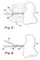
- FIG. 5is a schematic view of a process for creating a pathway of excited molecules
- FIG. 6is a schematic view of a process for ionizing the excited molecules in the pathway
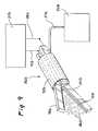
- FIG. 7is an axial cross section view illustrating a handpiece having a housing and probe and being adapted for use in a monopolar electrosurgery procedure
- FIG. 8is a side elevation view of a handpiece adapted for use in a bipolar electrosurgery procedure
- FIG. 9is a perspective view of a handpiece including jaws
- FIG. 10is a perspective view of a handpiece having a blade configuration
- FIG. 11 -FIG. 20illustrates a catheter of the present invention including a balloon providing for the controlled release of an inflation gas to provide the environmental gas for the present invention
- FIG. 11is a side elevation view of one embodiment of a balloon catheter
- FIG. 12is a top plan view of the embodiment of FIG. 11;
- FIG. 13is an end elevation view of the embodiment of FIG. 11;
- FIG. 14is a side elevation view of a further embodiment of a balloon catheter adapted for use in a bipolar configuration
- FIG. 15is a top plan view of the embodiment of FIG. 14;
- FIG. 16is an end elevation view of the embodiment of FIG. 14;
- FIG. 17is a side elevation view similar to FIG. 2 and showing a laser beam being defocused to facilitate electrosurgical coagulation;
- FIG. 18is a perspective view of an embodiment including two lasers with beams that converge toward the operative site of the patient;
- FIG. 19is an end view taken along lines XIX-XIY of FIG. 18.
- FIG. 20is an axial cross section view taken along lines XX—XX of FIG. 19 .
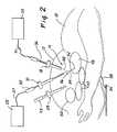
- FIG. 1A patient is illustrated in FIG. 1 and designated generally by the reference numeral 10 .
- the patient 10has an abdominal wall 12 which defines an interior abdominal cavity of 14 .
- the patient 10is disposed on an operating table 16 and is prepared for laparoscopic surgery which is performed through the abdominal wall 12 within the abdominal cavity 14 .
- a laparoscopic procedureis facilitated by a plurality of elongate trocars 18 , 21 , and 23 , which are inserted through the abdominal wall and into the abdominal cavity 14 .
- Various instrumentscan be inserted into and removed from the trocars 18 , 21 , and 23 to facilitate a particular operative procedure within the abdominal cavity 14 .
- the patient 10is prepared for electrosurgery in a laparoscopic procedure.
- a laser 25is provided and connected through an optical fiber 27 to a laser probe 30 extending through the trocar 21 .
- an electrosurgical generator 32is provided in a monopolar configuration with a grounding plate 34 and an electrosurgery handpiece 36 .
- the grounding plate 34is connected to the generator 32 through a lead 38 , and provides a large area of electrical contact with the patient 10 .
- the handpiece 36is connected to the generator through a lead 41 and can be inserted through the trocar 18 into the abdominal cavity 14 .
- Other instruments useful in this proceduremight include a laparoscope 43 which might typically be inserted through the trocar 23 to provide for illumination and visualization within the cavity 14 .
- FIG. 2This arrangement of trocars and instruments is best illustrated in the side elevation view of FIG. 2 .
- the abdominal cavity 14is illustrated to include various organs such as a stomach 45 , kidneys 47 , and bladder 50 .
- electrosurgeryis being performed at an operative site 52 on the stomach 45 .
- the abdominal cavity 14is initially inflated or insufflated with a gas such as carbon dioxide. This insufflation distends the abdominal wall 12 thereby increasing the volume of the working area within the abdominal cavity 14 .
- the laser probe 30can be inserted through the trocar 21 and activated to direct a laser beam 54 toward the operative site 52 .
- the laser beam 54energies the molecules of the insufflation gas to create a pathway 56 leading toward the operative site 52 .
- the electrosurgical generator 32can be activated to produce an electrosurgical potential between the handpiece 36 and the grounding pad 34 . This potential will produce a spark or arc 58 which is intended to produce an electrosurgical effect at the operative site 52 . Control of this spark or arc 58 is maintained by introducing the arc 58 in proximity to the pathway 56 of excited molecules.
- electrosurgical potentialionizes the excited molecules along the pathway 56 to create a path of least resistance leading toward the operative site 52 .
- the arc 58can create the desired electrosurgical effect at the operative site 52 .
- an atom 61is illustrated schematically to include a nucleus 63 and two electron orbits or shells 65 and 67 .
- Two electrons 720 and 72are normally present in the inner most or first shell 65 while four electrons 74 are typically present in the second shell 67 , the outer most shell in this particular atom.
- the atoms associated with the various elements in the periodic tablediffer primarily in the makeup of the nucleus 63 , as well as the number of shells, such as the shells 65 , 70 , and number of electrons, such as the electrons 70 , 72 and 74 .
- the electrons 70 , 72 , 74when they are exposed to an energy source, such as an electrical probe 76 .
- an energy sourcesuch as an electrical probe 76 .
- the associated electronshave different energy levels. These energy levels are lowest at the inner shell 65 and highest at the outer shell 67 .
- the electronsIn response to the electrical field produced by the electrode 76 , the electrons, such as the electron 72 , become energized. As the energy level of the electron 72 increases, it moves from the lower energy shell 65 to the higher energy shell 67 as shown by an arrow 78 in FIG. 4 A. As the electron 72 moves outwardly, it leaves an electron void or hole 81 in the first shell 65 .
- the electron 72 in the outer shell 67is unstable particularly with the electron hole 81 present in the lower energy shell 65 .
- the electron 72will tend to fall back into the inner shell 65 as illustrated by the arrow 83 in FIG. 4 b .
- the difference in energyis released as a photon 85
- the photon released in this processhas a known energy level equal to the product of its frequency (f) and its wavelength ( ⁇ ).
- thisdescribes the operation of a laser wherein the photons are collected and collimated into a laser beam such as the beam 54 (FIG. 2 ).
- a laser beamsuch as the beam 54 (FIG. 2 ).
- the energized electronsmove between the shells 65 , 67 of the atom 61 .
- the atomis merely excited, not ionized. This excited atom is designated in FIG. 4A by the reference numeral 86 .
- the energy of the electronsuch as the electron 72 may exceed that necessary to maintain it in the outer shell 67 .
- the electron 72may be separated from the atom 61 , as a free electron 87 . This leaves an ionized atom 88 in a charged state.
- the free electrons which result from this ionizationchange the properties of the pathway 56 (FIG. 2 ). What was heretofore merely a pathway of excited atoms is now a pathway of ionized atoms which for the first time offers a path of least resistance for the electrical arc (FIG. 2 ).
- the pathway 56 illustrated in FIG. 2 and FIG. 5can initially be established merely by the excited atoms 86 . Although these excited atoms 86 will not produce a path of least resistance, they nevertheless establishes a pathway of atoms which have already reached an excited state. Under these circumstances, the electrosurgical handpiece 36 can provide the remaining energy necessary to ionize the excited molecules as illustrated in FIG. 4 C. The resulting release of free electrons (shown by the arrow 87 in FIG. 4C) makes the pathway 56 a path of least resistance for subsequent delivery of the arc 58 toward the operative site 52 .
- the amount of energy, and particularly the frequency of the energy, used to energize the atom 61it is of particular interest to the present invention to contemplate the amount of energy, and particularly the frequency of the energy, used to energize the atom 61 . It has been noted that the amount of energy required to displace an electron between atom shells varies with the particular atom involved. Thus, an atom of oxygen would require a different level of excitation energy then would an atom of carbon, for example. In addition, the amount of excitation power required is reduced when it is applied at a frequency which is dependent upon the excitation frequency of a particular atom. Importantly, when the excitation power is applied at a frequency dependent upon the excitation frequency of the atom, the amount of power required is reduced.
- the excitation frequency in this caseis the same as the frequency previously discussed with reference to the energy of the photon 85 (FIG. 4 B). Energy applied at this excitation frequency, or a harmonic thereof, requires less power to create the excited atom, such as the atom 86 .
- the photon frequency of the laser 86is chosen to be the fundamental frequency (or the harmonic thereof) of the excitation frequency associated with the environmental gas, the power required for excitation can be greatly reduced.
- the same power advantagescan be achieved by choosing the laser 76 with a photon frequency equal to the excitation frequency or any integer multiple or divisor thereof.
- lasersthere are several types of lasers including gas discharge lasers as well as crystal and diode lasers.
- Each laserhas its own photon frequency which can be chosen relative to the excitation frequency of the environmental gas being used.
- gas discharged lasersare easiest to contemplate with the present invention, as it is only necessary to choose the particular laser having a discharge gas which is the same as that of the environmental gas used in the electrosurgical process.
- the environmental gaswill dictate the choice of the laser, while in other cases, the laser will dictate the choice of the environmental gas.
- carbon dioxideis most commonly used as an insufflation gas. This gas necessarily defines the environmental gas for an electrosurgical laparoscopic procedure.
- the best choice for a laser under these circumstanceswould be a carbon dioxide discharge laser. This laser would require the least power to create the pathway of excited atoms in an insufflated laparoscopic procedure using carbon dioxide as the insulation gas.
- the handpiece 36includes a housing 90 communicating with an elongate probe 92 .
- a gas cartridge 94can be carried by the housing 90 and adapted to release gas molecules 96 into the housing 90 and through the probe 92 .
- These molecules 96would provide the environmental gas in those procedures not otherwise providing an insufflation gas.
- the laser 25 and associated batteries 98could also be carried in the housing 90 . Activation of the laser 25 through the optical fiber 27 would energize the atoms associated with the gas molecules 96 to create the energized pathway.
- the handpiece 36could be coupled through the lead 41 to the electrosurgical generator 32 .
- the generator 32in a monopolar configuration would also be coupled through the lead 38 to the groundplate 34 disposed between the patient 10 and the operating table 16 .
- Activation of the electrosurgical generator 32would produce the electrosurgical power necessary to ionize the atoms of excited gas in the pathway 56 . As previously discussed, this would create the path of less resistance for subsequent electrosurgical arcing to the operative site 52 on the patient 10 .
- the handpiece 36might be constructed as illustrated in FIG. 8 .
- elements of structure similar to those previously discussedare designated with the same reference numeral followed by the lowercase letter “a.”
- the handpiece 36is shown with the probe 92 a including the optical fiber 27 a , and the gas molecules 96 a are energized by the laser beam 54 a .
- the probe 92 aincludes two electrodes 99 and 101 which are connected respectively to the leads 38 a and 41 a of the electrosurgical generator 32 a .
- the spark or arc 58 awill jump between the electrodes 99 and 101 along the pathway 56 of energized free electrons 87 a.
- FIG. 9Another embodiment for the hand piece 36 is illustrated in FIG. 9 wherein elements of structure similar to those previously disclosed on designated with the same reference followed by the lowercase letter “b.”
- the probe 92 bincludes the two electrodes 99 b and 101 b in a bipolar configuration, with the electrode 101 b being provided with fiberoptic apertures 103 .
- Operation of this embodimentis similar to that of FIG. 8 in that the environmental gases can be carried through the probe 92 b to the vicinity of the electrodes 99 b and 101 b .
- the laser 25 bcan be coupled through the optical fiber 27 b to the fiber apertures 103 in order to excite the molecules of environmental gas.
- Electrosurgical powercan then be provided by the generator 32 b and through the leads 38 b and 41 b to the electrodes 101 b and 99 b , respectively. This will produce the desired ionization of the excited atoms 86 b and facilitate arcing along a controlled pathway between the electrodes 98 b and 101 b.
- FIG. 10illustrates an embodiment of the handpiece 36 which is adapted to function as a laser knife or scalpel.
- elements of structure similar to those previously discussedwill be designated with the same reference numerals followed by the lowercase letter “c.”
- the handpiece 36is illustrated to be completely self-contained and with powering both the laser 25 c and the electrosurgery generator 32 c.
- the laser 25 ccan initially be operated to energize the environmental gas molecules.
- the embodiment of FIG. 10provides for the laser beam 54 c to be moveable through an aperture 105 to create the pathway 56 c having an elongate and generally planar configuration.
- the electrode 27 cis activated to ionize the atoms in the pathway 56 c . This facilitates the controlled delivery of the electrosurgical spark or arc 58 C along the planar pathway 56 c.
- FIG. 11A further embodiment of the invention is illustrated in the side elevation view of FIG. 11 where elements of structure similar to those previously disclosed are designated with the same reference numeral followed by the lowercase letter “d.”
- the concept of the inventionis embodied as a catheter 108 having a hub 110 and a catheter body 112 which extends to a distal end 114 along an axis 115 .
- the electrosurgical lead 41 b from the electrosurgical generator 32 (FIG. 1 ), and the optical fiber 27 d from the laser 25 (FIG. 1 )can be introduced into the hub 110 and extended through the catheter body 112 .
- the electrosurgical lead 41 dcan be terminated in an electrode which in a preferred embodiment comprises a wire 116 .
- the optical fiber 27 dcan be provided with a distal tip having facets 118 , or a refractive index coating selectively removed, to permit the escape of light in a direction desired for the pathway 56 d . In the illustrated embodiment, this direction is laterally of the axis 115 as shown by the pathway arrows 56 d .
- the wire electrode 116 and the optical fiber 27 dmay be all that is required to implement the concept of the present invention. Applying laser energy through the optical fiber 27 d will excite the atoms of the environmental gas creating the pathway 56 d in the direction dictated for example by the facets 118 . Activating the wire electrode 116 will then cause electrosurgical energy to ionize the pathway 56 d and create the desired electrosurgical effect.
- a balloon 121can also be provided at the distal end 114 of the catheter 108 to perform typical catheter balloon functions.
- the balloon 121has an inflatable wall 123 which includes portions that define a series of perforations 125 .
- the balloon 121may be centered on the catheter body 112 with the faceted distal tip 117 of the optical fiber 27 d disposed within the balloon 121 , for example near the axis 115 .
- the wire electrode 116is preferably disposed along the outer surface of the balloon wall 123 .
- gascan be introduced through the hub 110 and along the catheter body 112 to inflate the balloon 121 .
- the inflation gasis permitted to leak through the perforations 125 into the environment surrounding the balloon 121 .
- the laser 25(FIG. 1) can be activated to direct laser energy along the optical fiber 27 d and to energize the atoms of the environmental gas along the pathway 56 d .
- this pathway 56 Dwill extend from within the balloon 121 , through the inflation gas within the balloon 121 , outwardly through the perforations 125 , and through the environmental gas toward the operative site.
- electrosurgical powerwill follow the pathway 56 a to create the electrosurgical effect.
- the embodiment of a cathetercan be a particular advantage where the electrosurgical effect is desired within a body conduit, such as the ureter.
- the addition of the balloon 121can produce many synergistic effects.
- the mere inflation of the ballooncan carry the electrode wire 116 into closer proximity to the wall of the conduit.
- the gas used to inflate the wall 123 of the balloon 121can also provide the environmental gas for the electrosurgical procedure.
- the balloon 121can be used to release the inflation gas into the environment and in a predetermined direction.
- the catheter 108 eincludes the hub 110 e and the catheter body 12 e .
- the balloon 121 eis also included with its wall 123 e and perforations 125 e .
- the electrode wire 116 eis disposed along the outer surface of the balloon wall 123 .
- the distal tip 117 of the optical fiber 127 eis also carried on the outer surface of the balloon wall 123 .
- inflation gascan be introduce into the balloon 121 e thereby expanding the wall 123 and carrying the electrode wire 116 e and optical fiber distal tip 117 radially outwardly. As before, this inflation gas can be permitted to leak through the perforations 125 e into the environment.
- the distal tip 117 ewill direct laser energy outwardly from the wall 123 e of the balloon 121 e in order to create the energized pathway 156 e .
- activation of the electrode wire 116 ewill follow this pathway 156 e toward the operative site.
- FIG. 17A further embodiment of the laser probe is illustrated in FIG. 17 which provides a view similar to that of FIG. 2 .
- elements of structure similar to those previously disclosedwill be designated with the same reference numeral followed by the lower case letter “f.”
- the probe 30 fhas a distal end tip that is provided with a lens 130 at its distal end 114 f .
- This lens 130tends to diverge the laser beam 54 f so that the operative site 52 f is defined by an area, rather than a point as previously illustrated for the embodiment of FIG. 2 .
- the pathway 56 f of excited atomsalso expands as it approaches the area of the operative site 52 f .
- the spark or arc 58 fwill be randomly directed within the area of the operative site 52 f . This can be of particular advantage when the desired electrosurgical effect is to cauterize or coagulate over a wide area of the operative site 52 f.
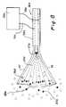
- FIGS. 18-20A further embodiment of the handpiece 36 is illustrated in FIGS. 18-20 wherein elements of structure similar to those previously discussed are designated with the same reference numeral followed by the lower case “g.”
- the handpiece 36 gincludes the probe 92 g containing at least the optical fiber 27 g and the electrosurgical electrode 101 g .
- the probe 92 galso contains a second optical fiber 132 .
- the two optical fibers 27 g and 132are distally terminated at lenses 134 and 136 , respectively.
- the lens 134 associated with the fiber 27causes the laser beam 54 g to converge as illustrated.
- the lens 136 associated with the fiber 132causes a laser beam 138 to converge.
- these two laser beams 54 g and 138can also be converged toward the operative site 52 .
- This embodimentoffers the advantage of providing increased laser power for development of the pathway 56 g . Even with this increased power, the pathway 56 g can be controlled to converge the electrosurgical energy toward the operative site 52 g.
Landscapes
- Health & Medical Sciences (AREA)
- Surgery (AREA)
- Life Sciences & Earth Sciences (AREA)
- Engineering & Computer Science (AREA)
- Physics & Mathematics (AREA)
- Medical Informatics (AREA)
- Animal Behavior & Ethology (AREA)
- Nuclear Medicine, Radiotherapy & Molecular Imaging (AREA)
- Biomedical Technology (AREA)
- Heart & Thoracic Surgery (AREA)
- Veterinary Medicine (AREA)
- Molecular Biology (AREA)
- Otolaryngology (AREA)
- General Health & Medical Sciences (AREA)
- Public Health (AREA)
- Plasma & Fusion (AREA)
- Cardiology (AREA)
- Optics & Photonics (AREA)
- Electromagnetism (AREA)
- Laser Surgery Devices (AREA)
- Surgical Instruments (AREA)
Abstract
Description
Claims (48)
Priority Applications (6)
| Application Number | Priority Date | Filing Date | Title |
|---|---|---|---|
| US10/057,227US6740081B2 (en) | 2002-01-25 | 2002-01-25 | Electrosurgery with improved control apparatus and method |
| EP02793820AEP1467669A2 (en) | 2002-01-25 | 2002-10-24 | Electrosurgery with improved control apparatus and method |
| CA002473745ACA2473745A1 (en) | 2002-01-25 | 2002-10-24 | Electrosurgery with improved control apparatus and method |
| JP2003563414AJP2005515825A (en) | 2002-01-25 | 2002-10-24 | Electrosurgical instrument using improved control device and method of handling the same |
| PCT/US2002/034218WO2003063716A2 (en) | 2002-01-25 | 2002-10-24 | Electrosurgery with improved control apparatus and method |
| US10/777,879US20040167513A1 (en) | 2002-01-25 | 2004-02-11 | Electrosurgery with improved control apparatus and method |
Applications Claiming Priority (1)
| Application Number | Priority Date | Filing Date | Title |
|---|---|---|---|
| US10/057,227US6740081B2 (en) | 2002-01-25 | 2002-01-25 | Electrosurgery with improved control apparatus and method |
Related Child Applications (1)
| Application Number | Title | Priority Date | Filing Date |
|---|---|---|---|
| US10/777,879DivisionUS20040167513A1 (en) | 2002-01-25 | 2004-02-11 | Electrosurgery with improved control apparatus and method |
Publications (2)
| Publication Number | Publication Date |
|---|---|
| US20030144654A1 US20030144654A1 (en) | 2003-07-31 |
| US6740081B2true US6740081B2 (en) | 2004-05-25 |
Family
ID=27609400
Family Applications (2)
| Application Number | Title | Priority Date | Filing Date |
|---|---|---|---|
| US10/057,227Expired - LifetimeUS6740081B2 (en) | 2002-01-25 | 2002-01-25 | Electrosurgery with improved control apparatus and method |
| US10/777,879AbandonedUS20040167513A1 (en) | 2002-01-25 | 2004-02-11 | Electrosurgery with improved control apparatus and method |
Family Applications After (1)
| Application Number | Title | Priority Date | Filing Date |
|---|---|---|---|
| US10/777,879AbandonedUS20040167513A1 (en) | 2002-01-25 | 2004-02-11 | Electrosurgery with improved control apparatus and method |
Country Status (5)
| Country | Link |
|---|---|
| US (2) | US6740081B2 (en) |
| EP (1) | EP1467669A2 (en) |
| JP (1) | JP2005515825A (en) |
| CA (1) | CA2473745A1 (en) |
| WO (1) | WO2003063716A2 (en) |
Cited By (42)
| Publication number | Priority date | Publication date | Assignee | Title |
|---|---|---|---|---|
| US20060052772A1 (en)* | 2004-02-03 | 2006-03-09 | Sartor Joe D | Gas-enhanced surgical instrument |
| US20090312768A1 (en)* | 2008-06-13 | 2009-12-17 | Aspen Medtech, Inc. | Shockwave balloon catheter system |
| US20100016856A1 (en)* | 1999-10-05 | 2010-01-21 | Platt Jr Robert C | Articulating Ionizable Gas Coagulator |
| US20100036294A1 (en)* | 2008-05-07 | 2010-02-11 | Robert Mantell | Radially-Firing Electrohydraulic Lithotripsy Probe |
| US20100114020A1 (en)* | 2008-11-05 | 2010-05-06 | Daniel Hawkins | Shockwave valvuloplasty catheter system |
| US20100114065A1 (en)* | 2008-11-04 | 2010-05-06 | Daniel Hawkins | Drug delivery shockwave balloon catheter system |
| US20110054454A1 (en)* | 2009-08-26 | 2011-03-03 | Tyco Healthcare Group Lp | Gas-Enhanced Surgical Instrument with Mechanism for Cylinder Puncture |
| US8709075B2 (en) | 2011-11-08 | 2014-04-29 | Shockwave Medical, Inc. | Shock wave valvuloplasty device with moveable shock wave generator |
| US8728091B2 (en) | 2012-09-13 | 2014-05-20 | Shockwave Medical, Inc. | Shockwave catheter system with energy control |
| US8747416B2 (en) | 2012-08-06 | 2014-06-10 | Shockwave Medical, Inc. | Low profile electrodes for an angioplasty shock wave catheter |
| US9011463B2 (en) | 2012-06-27 | 2015-04-21 | Shockwave Medical, Inc. | Shock wave balloon catheter with multiple shock wave sources |
| US9072534B2 (en) | 2008-06-13 | 2015-07-07 | Shockwave Medical, Inc. | Non-cavitation shockwave balloon catheter system |
| US9138249B2 (en) | 2012-08-17 | 2015-09-22 | Shockwave Medical, Inc. | Shock wave catheter system with arc preconditioning |
| US9220521B2 (en) | 2012-08-06 | 2015-12-29 | Shockwave Medical, Inc. | Shockwave catheter |
| US9522012B2 (en) | 2012-09-13 | 2016-12-20 | Shockwave Medical, Inc. | Shockwave catheter system with energy control |
| US9730715B2 (en) | 2014-05-08 | 2017-08-15 | Shockwave Medical, Inc. | Shock wave guide wire |
| US10226265B2 (en) | 2016-04-25 | 2019-03-12 | Shockwave Medical, Inc. | Shock wave device with polarity switching |
| US10357264B2 (en) | 2016-12-06 | 2019-07-23 | Shockwave Medical, Inc. | Shock wave balloon catheter with insertable electrodes |
| US10441300B2 (en) | 2017-04-19 | 2019-10-15 | Shockwave Medical, Inc. | Drug delivery shock wave balloon catheter system |
| US10555744B2 (en) | 2015-11-18 | 2020-02-11 | Shockware Medical, Inc. | Shock wave electrodes |
| US10603058B2 (en) | 2013-03-11 | 2020-03-31 | Northgate Technologies, Inc. | Unfocused electrohydraulic lithotripter |
| US10646240B2 (en) | 2016-10-06 | 2020-05-12 | Shockwave Medical, Inc. | Aortic leaflet repair using shock wave applicators |
| US10702293B2 (en) | 2008-06-13 | 2020-07-07 | Shockwave Medical, Inc. | Two-stage method for treating calcified lesions within the wall of a blood vessel |
| US10709462B2 (en) | 2017-11-17 | 2020-07-14 | Shockwave Medical, Inc. | Low profile electrodes for a shock wave catheter |
| US10966737B2 (en) | 2017-06-19 | 2021-04-06 | Shockwave Medical, Inc. | Device and method for generating forward directed shock waves |
| US11020135B1 (en) | 2017-04-25 | 2021-06-01 | Shockwave Medical, Inc. | Shock wave device for treating vascular plaques |
| US11478261B2 (en) | 2019-09-24 | 2022-10-25 | Shockwave Medical, Inc. | System for treating thrombus in body lumens |
| US11596423B2 (en) | 2018-06-21 | 2023-03-07 | Shockwave Medical, Inc. | System for treating occlusions in body lumens |
| US11992232B2 (en) | 2020-10-27 | 2024-05-28 | Shockwave Medical, Inc. | System for treating thrombus in body lumens |
| US12023098B2 (en) | 2021-10-05 | 2024-07-02 | Shockwave Medical, Inc. | Lesion crossing shock wave catheter |
| US12035932B1 (en) | 2023-04-21 | 2024-07-16 | Shockwave Medical, Inc. | Intravascular lithotripsy catheter with slotted emitter bands |
| US12178458B1 (en) | 2024-05-16 | 2024-12-31 | Shockwave Medical, Inc. | Guidewireless shock wave catheters |
| US12220141B2 (en) | 2023-06-29 | 2025-02-11 | Shockwave Medical, Inc. | Catheter system with independently controllable bubble and arc generation |
| US12232755B2 (en) | 2020-12-11 | 2025-02-25 | Shockwave Medical, Inc. | Lesion crossing shock wave catheter |
| US12274460B2 (en) | 2019-09-24 | 2025-04-15 | Shockwave Medical, Inc. | Lesion crossing shock wave catheter |
| US12285237B2 (en) | 2020-01-13 | 2025-04-29 | Medlumics S.L. | Systems and methods for optical analysis and lesion prediction using ablation catheters |
| US12290268B2 (en) | 2023-03-31 | 2025-05-06 | Shockwave Medical, Inc. | Shockwave catheters for treating rhinosinusitis |
| US12310605B2 (en) | 2012-08-08 | 2025-05-27 | Shockwave Medical, Inc. | Shock wave valvuloplasty with multiple balloons |
| US12402899B2 (en) | 2023-11-30 | 2025-09-02 | Shockwave Medical, Inc. | Systems, devices, and methods for generating shock waves in a forward direction |
| US12426904B2 (en) | 2023-11-17 | 2025-09-30 | Shockwave Medical, Inc. | Intravascular lithotripsy catheter with oscillating impactor |
| US12426938B2 (en) | 2019-09-24 | 2025-09-30 | Shockwave Medical, Inc. | Low profile electrodes for a shock wave catheter |
| US12433620B2 (en) | 2024-02-23 | 2025-10-07 | Shockwave Medical, Inc. | Locus emitter shock wave catheter devices with increased longevity and higher sonic output |
Families Citing this family (63)
| Publication number | Priority date | Publication date | Assignee | Title |
|---|---|---|---|---|
| US8016823B2 (en) | 2003-01-18 | 2011-09-13 | Tsunami Medtech, Llc | Medical instrument and method of use |
| US7892229B2 (en) | 2003-01-18 | 2011-02-22 | Tsunami Medtech, Llc | Medical instruments and techniques for treating pulmonary disorders |
| US6616660B1 (en)* | 1999-10-05 | 2003-09-09 | Sherwood Services Ag | Multi-port side-fire coagulator |
| US9433457B2 (en) | 2000-12-09 | 2016-09-06 | Tsunami Medtech, Llc | Medical instruments and techniques for thermally-mediated therapies |
| US8444636B2 (en) | 2001-12-07 | 2013-05-21 | Tsunami Medtech, Llc | Medical instrument and method of use |
| DE10224153A1 (en)* | 2002-05-27 | 2003-12-11 | Celon Ag Medical Instruments | therapy device |
| US8579892B2 (en)* | 2003-10-07 | 2013-11-12 | Tsunami Medtech, Llc | Medical system and method of use |
| US7628787B2 (en)* | 2004-02-03 | 2009-12-08 | Covidien Ag | Self contained, gas-enhanced surgical instrument |
| US8226643B2 (en)* | 2004-02-03 | 2012-07-24 | Covidien Ag | Gas-enhanced surgical instrument with pressure safety feature |
| US7833222B2 (en) | 2004-02-03 | 2010-11-16 | Covidien Ag | Gas-enhanced surgical instrument with pressure safety feature |
| US8157795B2 (en)* | 2004-02-03 | 2012-04-17 | Covidien Ag | Portable argon system |
| US20070032785A1 (en) | 2005-08-03 | 2007-02-08 | Jennifer Diederich | Tissue evacuation device |
| US20110077628A1 (en)* | 2006-01-10 | 2011-03-31 | Tsunami Medtech, Llc | Medical system and method of use |
| US7691102B2 (en)* | 2006-03-03 | 2010-04-06 | Covidien Ag | Manifold for gas enhanced surgical instruments |
| US7648503B2 (en)* | 2006-03-08 | 2010-01-19 | Covidien Ag | Tissue coagulation method and device using inert gas |
| US8123744B2 (en) | 2006-08-29 | 2012-02-28 | Covidien Ag | Wound mediating device |
| EP2190373B1 (en) | 2007-08-23 | 2013-01-09 | Aegea Medical, Inc. | Uterine therapy device |
| US20090076505A1 (en)* | 2007-09-13 | 2009-03-19 | Arts Gene H | Electrosurgical instrument |
| US8377059B2 (en) | 2007-11-28 | 2013-02-19 | Covidien Ag | Cordless medical cauterization and cutting device |
| US9050098B2 (en) | 2007-11-28 | 2015-06-09 | Covidien Ag | Cordless medical cauterization and cutting device |
| US8758342B2 (en) | 2007-11-28 | 2014-06-24 | Covidien Ag | Cordless power-assisted medical cauterization and cutting device |
| AU2014202525B2 (en)* | 2007-11-28 | 2014-07-10 | Covidien Ag | Cordless power-assisted medical cauterization and cutting device |
| US9924992B2 (en) | 2008-02-20 | 2018-03-27 | Tsunami Medtech, Llc | Medical system and method of use |
| US8721632B2 (en) | 2008-09-09 | 2014-05-13 | Tsunami Medtech, Llc | Methods for delivering energy into a target tissue of a body |
| US20100042088A1 (en)* | 2008-08-14 | 2010-02-18 | Arts Gene H | Surgical Gas Plasma Ignition Apparatus and Method |
| US8226642B2 (en)* | 2008-08-14 | 2012-07-24 | Tyco Healthcare Group Lp | Surgical gas plasma ignition apparatus and method |
| US9700365B2 (en) | 2008-10-06 | 2017-07-11 | Santa Anna Tech Llc | Method and apparatus for the ablation of gastrointestinal tissue |
| US9561066B2 (en) | 2008-10-06 | 2017-02-07 | Virender K. Sharma | Method and apparatus for tissue ablation |
| US10064697B2 (en) | 2008-10-06 | 2018-09-04 | Santa Anna Tech Llc | Vapor based ablation system for treating various indications |
| US10695126B2 (en) | 2008-10-06 | 2020-06-30 | Santa Anna Tech Llc | Catheter with a double balloon structure to generate and apply a heated ablative zone to tissue |
| US9561068B2 (en) | 2008-10-06 | 2017-02-07 | Virender K. Sharma | Method and apparatus for tissue ablation |
| US9782217B2 (en) | 2008-11-13 | 2017-10-10 | Covidien Ag | Radio frequency generator and method for a cordless medical cauterization and cutting device |
| US11284931B2 (en) | 2009-02-03 | 2022-03-29 | Tsunami Medtech, Llc | Medical systems and methods for ablating and absorbing tissue |
| US8900223B2 (en) | 2009-11-06 | 2014-12-02 | Tsunami Medtech, Llc | Tissue ablation systems and methods of use |
| US11896282B2 (en)* | 2009-11-13 | 2024-02-13 | Hermes Innovations Llc | Tissue ablation systems and method |
| US9161801B2 (en) | 2009-12-30 | 2015-10-20 | Tsunami Medtech, Llc | Medical system and method of use |
| US20120041770A1 (en)* | 2010-08-10 | 2012-02-16 | Richard Philippe | Systems, methods, and apparatus for provisioning and tracking medical supplies for medical procedures |
| US9943353B2 (en) | 2013-03-15 | 2018-04-17 | Tsunami Medtech, Llc | Medical system and method of use |
| ES2912362T3 (en) | 2010-11-09 | 2022-05-25 | Aegea Medical Inc | Method of placement and apparatus for delivering steam to the uterus |
| WO2013095695A1 (en)* | 2011-04-10 | 2013-06-27 | Vanessa Vera | Systems and methods to deliver laser pulses into the eye |
| CA2851355C (en) | 2011-10-07 | 2020-02-18 | Aegea Medical Inc. | Integrity testing method and apparatus for delivering vapor to the uterus |
| EP3964151A3 (en) | 2013-01-17 | 2022-03-30 | Virender K. Sharma | Apparatus for tissue ablation |
| US10179019B2 (en) | 2014-05-22 | 2019-01-15 | Aegea Medical Inc. | Integrity testing method and apparatus for delivering vapor to the uterus |
| EP3145425B1 (en) | 2014-05-22 | 2024-10-23 | CooperSurgical, Inc. | Systems for performing endometrial ablation |
| EP3416551B1 (en) | 2016-02-19 | 2022-10-12 | Aegea Medical Inc. | Apparatus for determining the integrity of a bodily cavity |
| WO2017176240A1 (en) | 2016-04-04 | 2017-10-12 | Gyrus Acmi, Inc., D.B.A. Olympus Surgical Technologies Amercia | An electrosurgical illuminating instrument |
| US12364537B2 (en) | 2016-05-02 | 2025-07-22 | Santa Anna Tech Llc | Catheter with a double balloon structure to generate and apply a heated ablative zone to tissue |
| US11331140B2 (en) | 2016-05-19 | 2022-05-17 | Aqua Heart, Inc. | Heated vapor ablation systems and methods for treating cardiac conditions |
| EP3609408A4 (en) | 2017-04-10 | 2021-03-10 | U.S. Patent Innovations LLC | Electrosurgical gas control module |
| JP7356978B2 (en)* | 2018-04-10 | 2023-10-05 | ユー.エス. パテント イノベーションズ エルエルシー | Gas-enhanced electrosurgical generator |
| EP3801324B1 (en) | 2018-06-01 | 2025-05-28 | Aqua Medical, Inc. | Vapor generation and delivery systems |
| US12402946B2 (en) | 2019-06-19 | 2025-09-02 | Boston Scientific Scimed, Inc. | Breakdown of laser pulse energy for breakup of vascular calcium |
| US12280223B2 (en) | 2019-06-26 | 2025-04-22 | Boston Scientific Scimed, Inc. | Focusing element for plasma system to disrupt vascular lesions |
| US12102384B2 (en) | 2019-11-13 | 2024-10-01 | Bolt Medical, Inc. | Dynamic intravascular lithotripsy device with movable energy guide |
| US12274497B2 (en) | 2019-12-18 | 2025-04-15 | Bolt Medical, Inc. | Multiplexer for laser-driven intravascular lithotripsy device |
| US12295654B2 (en) | 2020-06-03 | 2025-05-13 | Boston Scientific Scimed, Inc. | System and method for maintaining balloon integrity within intravascular lithotripsy device with plasma generator |
| US12076080B2 (en)* | 2020-06-04 | 2024-09-03 | University Of Iowa Research Foundation | Compact laser scalpel and method for preferential ablation of tumor tissue |
| WO2022147472A1 (en)* | 2020-12-31 | 2022-07-07 | Dmg Group, Llc | Integrated probe-ablation device and systems for sensory nerve ablation in a joint |
| EP4277548B1 (en) | 2021-01-12 | 2025-06-04 | Bolt Medical, Inc. | Balloon assembly for valvuloplasty catheter system |
| US20220249165A1 (en)* | 2021-02-10 | 2022-08-11 | Bolt Medical, Inc. | Optical assemblies to improve energy coupling to pressure wave generator of an intravascular lithotripsy device |
| US12089861B2 (en) | 2021-08-05 | 2024-09-17 | Nextern Innovation, Llc | Intravascular lithotripsy system and device |
| CR20240179A (en) | 2021-10-19 | 2024-06-12 | Shockwave Medical Inc | Intravascular lithotripsy catheter with interfering shock waves |
| US11839391B2 (en) | 2021-12-14 | 2023-12-12 | Bolt Medical, Inc. | Optical emitter housing assembly for intravascular lithotripsy device |
Citations (20)
| Publication number | Priority date | Publication date | Assignee | Title |
|---|---|---|---|---|
| US3775638A (en) | 1972-03-27 | 1973-11-27 | Versar Inc | Establishing highly conductive path in gas by thermal guidance of discharge |
| US4040426A (en) | 1976-01-16 | 1977-08-09 | Valleylab, Inc. | Electrosurgical method and apparatus for initiating an electrical discharge in an inert gas flow |
| US4057064A (en) | 1976-01-16 | 1977-11-08 | Valleylab, Inc. | Electrosurgical method and apparatus for initiating an electrical discharge in an inert gas flow |
| US4060088A (en) | 1976-01-16 | 1977-11-29 | Valleylab, Inc. | Electrosurgical method and apparatus for establishing an electrical discharge in an inert gas flow |
| US4781175A (en)* | 1986-04-08 | 1988-11-01 | C. R. Bard, Inc. | Electrosurgical conductive gas stream technique of achieving improved eschar for coagulation |
| US4901720A (en)* | 1986-04-08 | 1990-02-20 | C. R. Bard, Inc. | Power control for beam-type electrosurgical unit |
| US5507724A (en)* | 1992-07-01 | 1996-04-16 | Genetronics, Inc. | Electroporation and iontophoresis apparatus and method for insertion of drugs and genes into cells |
| US5509916A (en) | 1994-08-12 | 1996-04-23 | Valleylab Inc. | Laser-assisted electrosurgery system |
| US5588432A (en)* | 1988-03-21 | 1996-12-31 | Boston Scientific Corporation | Catheters for imaging, sensing electrical potentials, and ablating tissue |
| US5599296A (en)* | 1991-02-14 | 1997-02-04 | Wayne State University | Apparatus and method of delivery of gas-supersaturated liquids |
| US5704908A (en)* | 1996-10-10 | 1998-01-06 | Genetronics, Inc. | Electroporation and iontophoresis catheter with porous balloon |
| US5720745A (en) | 1992-11-24 | 1998-02-24 | Erbe Electromedizin Gmbh | Electrosurgical unit and method for achieving coagulation of biological tissue |
| US6027501A (en) | 1995-06-23 | 2000-02-22 | Gyrus Medical Limited | Electrosurgical instrument |
| US6039734A (en)* | 1995-10-24 | 2000-03-21 | Gyrus Medical Limited | Electrosurgical hand-held battery-operated instrument |
| US6179835B1 (en)* | 1996-01-19 | 2001-01-30 | Ep Technologies, Inc. | Expandable-collapsible electrode structures made of electrically conductive material |
| US6191386B1 (en) | 1999-04-22 | 2001-02-20 | The Ohio State University | Method and apparatus for initiating, directing and constricting electrical discharge arcs |
| US6234178B1 (en) | 1996-01-09 | 2001-05-22 | Gyrus Medical Limited | Electrosurgical instrument |
| US6238339B1 (en)* | 1991-06-20 | 2001-05-29 | Instrumentarium Corp. | Remote sensing tonometric catheter apparatus and method |
| US6387088B1 (en)* | 1999-06-30 | 2002-05-14 | John H. Shattuck | Photoionization enabled electrochemical material removal techniques for use in biomedical fields |
| US6425877B1 (en)* | 1999-04-02 | 2002-07-30 | Novasys Medical, Inc. | Treatment of tissue in the digestive circulatory respiratory urinary and reproductive systems |
- 2002
- 2002-01-25USUS10/057,227patent/US6740081B2/ennot_activeExpired - Lifetime
- 2002-10-24WOPCT/US2002/034218patent/WO2003063716A2/enactiveApplication Filing
- 2002-10-24EPEP02793820Apatent/EP1467669A2/ennot_activeWithdrawn
- 2002-10-24CACA002473745Apatent/CA2473745A1/ennot_activeAbandoned
- 2002-10-24JPJP2003563414Apatent/JP2005515825A/enactivePending
- 2004
- 2004-02-11USUS10/777,879patent/US20040167513A1/ennot_activeAbandoned
Patent Citations (22)
| Publication number | Priority date | Publication date | Assignee | Title |
|---|---|---|---|---|
| US3775638A (en) | 1972-03-27 | 1973-11-27 | Versar Inc | Establishing highly conductive path in gas by thermal guidance of discharge |
| US4040426A (en) | 1976-01-16 | 1977-08-09 | Valleylab, Inc. | Electrosurgical method and apparatus for initiating an electrical discharge in an inert gas flow |
| US4057064A (en) | 1976-01-16 | 1977-11-08 | Valleylab, Inc. | Electrosurgical method and apparatus for initiating an electrical discharge in an inert gas flow |
| US4060088A (en) | 1976-01-16 | 1977-11-29 | Valleylab, Inc. | Electrosurgical method and apparatus for establishing an electrical discharge in an inert gas flow |
| US4781175A (en)* | 1986-04-08 | 1988-11-01 | C. R. Bard, Inc. | Electrosurgical conductive gas stream technique of achieving improved eschar for coagulation |
| US4901720A (en)* | 1986-04-08 | 1990-02-20 | C. R. Bard, Inc. | Power control for beam-type electrosurgical unit |
| US5588432A (en)* | 1988-03-21 | 1996-12-31 | Boston Scientific Corporation | Catheters for imaging, sensing electrical potentials, and ablating tissue |
| US5599296A (en)* | 1991-02-14 | 1997-02-04 | Wayne State University | Apparatus and method of delivery of gas-supersaturated liquids |
| US5797874A (en)* | 1991-02-14 | 1998-08-25 | Wayne State University | Method of delivery of gas-supersaturated liquids |
| US6238339B1 (en)* | 1991-06-20 | 2001-05-29 | Instrumentarium Corp. | Remote sensing tonometric catheter apparatus and method |
| US5507724A (en)* | 1992-07-01 | 1996-04-16 | Genetronics, Inc. | Electroporation and iontophoresis apparatus and method for insertion of drugs and genes into cells |
| US5720745A (en) | 1992-11-24 | 1998-02-24 | Erbe Electromedizin Gmbh | Electrosurgical unit and method for achieving coagulation of biological tissue |
| US5509916A (en) | 1994-08-12 | 1996-04-23 | Valleylab Inc. | Laser-assisted electrosurgery system |
| US6174308B1 (en) | 1995-06-23 | 2001-01-16 | Gyrus Medical Limited | Electrosurgical instrument |
| US6027501A (en) | 1995-06-23 | 2000-02-22 | Gyrus Medical Limited | Electrosurgical instrument |
| US6039734A (en)* | 1995-10-24 | 2000-03-21 | Gyrus Medical Limited | Electrosurgical hand-held battery-operated instrument |
| US6234178B1 (en) | 1996-01-09 | 2001-05-22 | Gyrus Medical Limited | Electrosurgical instrument |
| US6179835B1 (en)* | 1996-01-19 | 2001-01-30 | Ep Technologies, Inc. | Expandable-collapsible electrode structures made of electrically conductive material |
| US5704908A (en)* | 1996-10-10 | 1998-01-06 | Genetronics, Inc. | Electroporation and iontophoresis catheter with porous balloon |
| US6425877B1 (en)* | 1999-04-02 | 2002-07-30 | Novasys Medical, Inc. | Treatment of tissue in the digestive circulatory respiratory urinary and reproductive systems |
| US6191386B1 (en) | 1999-04-22 | 2001-02-20 | The Ohio State University | Method and apparatus for initiating, directing and constricting electrical discharge arcs |
| US6387088B1 (en)* | 1999-06-30 | 2002-05-14 | John H. Shattuck | Photoionization enabled electrochemical material removal techniques for use in biomedical fields |
Cited By (103)
| Publication number | Priority date | Publication date | Assignee | Title |
|---|---|---|---|---|
| US8251995B2 (en) | 1999-10-05 | 2012-08-28 | Covidien Ag | Articulating ionizable gas coagulator |
| US20100016856A1 (en)* | 1999-10-05 | 2010-01-21 | Platt Jr Robert C | Articulating Ionizable Gas Coagulator |
| US20060052772A1 (en)* | 2004-02-03 | 2006-03-09 | Sartor Joe D | Gas-enhanced surgical instrument |
| US7572255B2 (en)* | 2004-02-03 | 2009-08-11 | Covidien Ag | Gas-enhanced surgical instrument |
| US20090275941A1 (en)* | 2004-02-03 | 2009-11-05 | Sartor Joe D | Gas-Enhanced Surgical Instrument |
| US8226644B2 (en)* | 2004-02-03 | 2012-07-24 | Covidien Ag | Gas-enhanced surgical instrument |
| US9579114B2 (en) | 2008-05-07 | 2017-02-28 | Northgate Technologies Inc. | Radially-firing electrohydraulic lithotripsy probe |
| US20100036294A1 (en)* | 2008-05-07 | 2010-02-11 | Robert Mantell | Radially-Firing Electrohydraulic Lithotripsy Probe |
| US11559318B2 (en) | 2008-05-07 | 2023-01-24 | Northgate Technologies Inc. | Radially-firing electrohydraulic lithotripsy probe |
| US10702293B2 (en) | 2008-06-13 | 2020-07-07 | Shockwave Medical, Inc. | Two-stage method for treating calcified lesions within the wall of a blood vessel |
| US9072534B2 (en) | 2008-06-13 | 2015-07-07 | Shockwave Medical, Inc. | Non-cavitation shockwave balloon catheter system |
| US20110166570A1 (en)* | 2008-06-13 | 2011-07-07 | Daniel Hawkins | Shockwave balloon catheter system |
| US20090312768A1 (en)* | 2008-06-13 | 2009-12-17 | Aspen Medtech, Inc. | Shockwave balloon catheter system |
| US10039561B2 (en) | 2008-06-13 | 2018-08-07 | Shockwave Medical, Inc. | Shockwave balloon catheter system |
| US11771449B2 (en) | 2008-06-13 | 2023-10-03 | Shockwave Medical, Inc. | Shockwave balloon catheter system |
| US8956371B2 (en) | 2008-06-13 | 2015-02-17 | Shockwave Medical, Inc. | Shockwave balloon catheter system |
| US8956374B2 (en) | 2008-06-13 | 2015-02-17 | Shockwave Medical, Inc. | Shockwave balloon catheter system |
| US10959743B2 (en) | 2008-06-13 | 2021-03-30 | Shockwave Medical, Inc. | Shockwave balloon catheter system |
| US9011462B2 (en) | 2008-06-13 | 2015-04-21 | Shockwave Medical, Inc. | Shockwave balloon catheter system |
| US20100114065A1 (en)* | 2008-11-04 | 2010-05-06 | Daniel Hawkins | Drug delivery shockwave balloon catheter system |
| US9180280B2 (en) | 2008-11-04 | 2015-11-10 | Shockwave Medical, Inc. | Drug delivery shockwave balloon catheter system |
| US9421025B2 (en) | 2008-11-05 | 2016-08-23 | Shockwave Medical, Inc. | Shockwave valvuloplasty catheter system |
| US9044619B2 (en) | 2008-11-05 | 2015-06-02 | Shockwave Medical, Inc. | Shockwave valvuloplasty catheter system |
| US10149690B2 (en) | 2008-11-05 | 2018-12-11 | Shockwave Medical, Inc. | Shockwave valvuloplasty catheter system |
| US11000299B2 (en) | 2008-11-05 | 2021-05-11 | Shockwave Medical, Inc. | Shockwave valvuloplasty catheter system |
| US9044618B2 (en) | 2008-11-05 | 2015-06-02 | Shockwave Medical, Inc. | Shockwave valvuloplasty catheter system |
| US12102342B2 (en) | 2008-11-05 | 2024-10-01 | Shockwave Medical, Inc. | Shockwave valvuloplasty catheter system |
| US20100114020A1 (en)* | 2008-11-05 | 2010-05-06 | Daniel Hawkins | Shockwave valvuloplasty catheter system |
| US20110054454A1 (en)* | 2009-08-26 | 2011-03-03 | Tyco Healthcare Group Lp | Gas-Enhanced Surgical Instrument with Mechanism for Cylinder Puncture |
| US8083737B2 (en) | 2009-08-26 | 2011-12-27 | Tyco Healthcare Group Lp | Gas-enhanced surgical instrument with mechanism for cylinder puncture |
| US9289224B2 (en) | 2011-11-08 | 2016-03-22 | Shockwave Medical, Inc. | Shock wave valvuloplasty device with moveable shock wave generator |
| US8709075B2 (en) | 2011-11-08 | 2014-04-29 | Shockwave Medical, Inc. | Shock wave valvuloplasty device with moveable shock wave generator |
| US10478202B2 (en) | 2011-11-08 | 2019-11-19 | Shockwave Medical, Inc. | Shock wave valvuloplasty device with moveable shock wave generator |
| US9814476B2 (en) | 2011-11-08 | 2017-11-14 | Shockwave Medical, Inc. | Shock wave valvuloplasty device with moveable shock wave generator |
| US11696799B2 (en) | 2012-06-27 | 2023-07-11 | Shockwave Medical, Inc. | Shock wave balloon catheter with multiple shock wave sources |
| US9642673B2 (en) | 2012-06-27 | 2017-05-09 | Shockwave Medical, Inc. | Shock wave balloon catheter with multiple shock wave sources |
| US12114923B2 (en) | 2012-06-27 | 2024-10-15 | Shockwave Medical, Inc. | Shock wave balloon catheter with multiple shock wave sources |
| US9993292B2 (en) | 2012-06-27 | 2018-06-12 | Shockwave Medical, Inc. | Shock wave balloon catheter with multiple shock wave sources |
| US10682178B2 (en) | 2012-06-27 | 2020-06-16 | Shockwave Medical, Inc. | Shock wave balloon catheter with multiple shock wave sources |
| US9011463B2 (en) | 2012-06-27 | 2015-04-21 | Shockwave Medical, Inc. | Shock wave balloon catheter with multiple shock wave sources |
| US9433428B2 (en) | 2012-08-06 | 2016-09-06 | Shockwave Medical, Inc. | Low profile electrodes for an angioplasty shock wave catheter |
| US10206698B2 (en) | 2012-08-06 | 2019-02-19 | Shockwave Medical, Inc. | Low profile electrodes for an angioplasty shock wave catheter |
| US12226111B2 (en) | 2012-08-06 | 2025-02-18 | Shockwave Medical, Inc. | Low profile electrodes for an angioplasty shock wave catheter |
| US8747416B2 (en) | 2012-08-06 | 2014-06-10 | Shockwave Medical, Inc. | Low profile electrodes for an angioplasty shock wave catheter |
| US11076874B2 (en) | 2012-08-06 | 2021-08-03 | Shockwave Medical, Inc. | Low profile electrodes for an angioplasty shock wave catheter |
| US8888788B2 (en) | 2012-08-06 | 2014-11-18 | Shockwave Medical, Inc. | Low profile electrodes for an angioplasty shock wave catheter |
| US9220521B2 (en) | 2012-08-06 | 2015-12-29 | Shockwave Medical, Inc. | Shockwave catheter |
| US12310605B2 (en) | 2012-08-08 | 2025-05-27 | Shockwave Medical, Inc. | Shock wave valvuloplasty with multiple balloons |
| US9138249B2 (en) | 2012-08-17 | 2015-09-22 | Shockwave Medical, Inc. | Shock wave catheter system with arc preconditioning |
| US9333000B2 (en) | 2012-09-13 | 2016-05-10 | Shockwave Medical, Inc. | Shockwave catheter system with energy control |
| US9005216B2 (en) | 2012-09-13 | 2015-04-14 | Shockwave Medical, Inc. | Shockwave catheter system with energy control |
| US9522012B2 (en) | 2012-09-13 | 2016-12-20 | Shockwave Medical, Inc. | Shockwave catheter system with energy control |
| US8728091B2 (en) | 2012-09-13 | 2014-05-20 | Shockwave Medical, Inc. | Shockwave catheter system with energy control |
| US11596424B2 (en) | 2012-09-13 | 2023-03-07 | Shockwave Medical, Inc. | Shockwave catheter system with energy control |
| US10517621B1 (en) | 2012-09-13 | 2019-12-31 | Shockwave Medical, Inc. | Method of managing energy delivered by a shockwave through dwell time compensation |
| US10517620B2 (en) | 2012-09-13 | 2019-12-31 | Shockwave Medical, Inc. | Shock wave catheter system with energy control |
| US12096950B2 (en) | 2012-09-13 | 2024-09-24 | Shockwave Medical, Inc. | Shockwave catheter system with energy control |
| US10973538B2 (en) | 2012-09-13 | 2021-04-13 | Shockwave Medical, Inc. | Shockwave catheter system with energy control |
| US11432834B2 (en) | 2012-09-13 | 2022-09-06 | Shockwave Medical, Inc. | Shock wave catheter system with energy control |
| US12193691B2 (en) | 2012-09-13 | 2025-01-14 | Shockwave Medical, Inc. | Shock wave catheter system with energy control |
| US10159505B2 (en) | 2012-09-13 | 2018-12-25 | Shockwave Medical, Inc. | Shockwave catheter system with energy control |
| US12048445B2 (en) | 2013-03-11 | 2024-07-30 | Northgate Technologies, Inc. | Unfocused electrohydraulic lithotripter |
| US10603058B2 (en) | 2013-03-11 | 2020-03-31 | Northgate Technologies, Inc. | Unfocused electrohydraulic lithotripter |
| US11559319B2 (en) | 2013-03-11 | 2023-01-24 | Northgate Technologies Inc. | Unfocused electrohydraulic lithotripter |
| US10420569B2 (en) | 2014-05-08 | 2019-09-24 | Shockwave Medical, Inc. | Shock wave guide wire |
| US9730715B2 (en) | 2014-05-08 | 2017-08-15 | Shockwave Medical, Inc. | Shock wave guide wire |
| US10555744B2 (en) | 2015-11-18 | 2020-02-11 | Shockware Medical, Inc. | Shock wave electrodes |
| US11337713B2 (en) | 2015-11-18 | 2022-05-24 | Shockwave Medical, Inc. | Shock wave electrodes |
| US12245782B2 (en) | 2015-11-18 | 2025-03-11 | Shockwave Medical, Inc. | Shock wave electrodes |
| US12064129B2 (en) | 2015-11-18 | 2024-08-20 | Shockwave Medical, Inc. | Shock wave electrodes |
| US10226265B2 (en) | 2016-04-25 | 2019-03-12 | Shockwave Medical, Inc. | Shock wave device with polarity switching |
| US11026707B2 (en) | 2016-04-25 | 2021-06-08 | Shockwave Medical, Inc. | Shock wave device with polarity switching |
| US10646240B2 (en) | 2016-10-06 | 2020-05-12 | Shockwave Medical, Inc. | Aortic leaflet repair using shock wave applicators |
| US12144516B2 (en) | 2016-10-06 | 2024-11-19 | Shockwave Medical, Inc. | Aortic leaflet repair using shock wave applicators |
| US11517337B2 (en) | 2016-10-06 | 2022-12-06 | Shockwave Medical, Inc. | Aortic leaflet repair using shock wave applicators |
| US10357264B2 (en) | 2016-12-06 | 2019-07-23 | Shockwave Medical, Inc. | Shock wave balloon catheter with insertable electrodes |
| US11517338B2 (en) | 2017-04-19 | 2022-12-06 | Shockwave Medical, Inc. | Drug delivery shock wave balloon catheter system |
| US10441300B2 (en) | 2017-04-19 | 2019-10-15 | Shockwave Medical, Inc. | Drug delivery shock wave balloon catheter system |
| US11020135B1 (en) | 2017-04-25 | 2021-06-01 | Shockwave Medical, Inc. | Shock wave device for treating vascular plaques |
| US11602363B2 (en) | 2017-06-19 | 2023-03-14 | Shockwave Medical, Inc. | Device and method for generating forward directed shock waves |
| US12232754B2 (en) | 2017-06-19 | 2025-02-25 | Shockwave Medical, Inc. | Device and method for generating forward directed shock waves |
| US10966737B2 (en) | 2017-06-19 | 2021-04-06 | Shockwave Medical, Inc. | Device and method for generating forward directed shock waves |
| US11950793B2 (en) | 2017-06-19 | 2024-04-09 | Shockwave Medical, Inc. | Device and method for generating forward directed shock waves |
| US11622780B2 (en) | 2017-11-17 | 2023-04-11 | Shockwave Medical, Inc. | Low profile electrodes for a shock wave catheter |
| US10709462B2 (en) | 2017-11-17 | 2020-07-14 | Shockwave Medical, Inc. | Low profile electrodes for a shock wave catheter |
| US12232752B2 (en) | 2017-11-17 | 2025-02-25 | Shockwave Medical, Inc. | Low profile electrodes for a shock wave catheter |
| US12114874B2 (en) | 2018-06-21 | 2024-10-15 | Shockwave Medical, Inc. | System for treating occlusions in body lumens |
| US11596423B2 (en) | 2018-06-21 | 2023-03-07 | Shockwave Medical, Inc. | System for treating occlusions in body lumens |
| US12274460B2 (en) | 2019-09-24 | 2025-04-15 | Shockwave Medical, Inc. | Lesion crossing shock wave catheter |
| US11478261B2 (en) | 2019-09-24 | 2022-10-25 | Shockwave Medical, Inc. | System for treating thrombus in body lumens |
| US12426938B2 (en) | 2019-09-24 | 2025-09-30 | Shockwave Medical, Inc. | Low profile electrodes for a shock wave catheter |
| US12402897B2 (en) | 2019-09-24 | 2025-09-02 | Shockwave Medical, Inc. | System for treating thrombus in body lumens |
| US12285237B2 (en) | 2020-01-13 | 2025-04-29 | Medlumics S.L. | Systems and methods for optical analysis and lesion prediction using ablation catheters |
| US11992232B2 (en) | 2020-10-27 | 2024-05-28 | Shockwave Medical, Inc. | System for treating thrombus in body lumens |
| US12232755B2 (en) | 2020-12-11 | 2025-02-25 | Shockwave Medical, Inc. | Lesion crossing shock wave catheter |
| US12023098B2 (en) | 2021-10-05 | 2024-07-02 | Shockwave Medical, Inc. | Lesion crossing shock wave catheter |
| US12290268B2 (en) | 2023-03-31 | 2025-05-06 | Shockwave Medical, Inc. | Shockwave catheters for treating rhinosinusitis |
| US12035932B1 (en) | 2023-04-21 | 2024-07-16 | Shockwave Medical, Inc. | Intravascular lithotripsy catheter with slotted emitter bands |
| US12220141B2 (en) | 2023-06-29 | 2025-02-11 | Shockwave Medical, Inc. | Catheter system with independently controllable bubble and arc generation |
| US12426904B2 (en) | 2023-11-17 | 2025-09-30 | Shockwave Medical, Inc. | Intravascular lithotripsy catheter with oscillating impactor |
| US12402899B2 (en) | 2023-11-30 | 2025-09-02 | Shockwave Medical, Inc. | Systems, devices, and methods for generating shock waves in a forward direction |
| US12433620B2 (en) | 2024-02-23 | 2025-10-07 | Shockwave Medical, Inc. | Locus emitter shock wave catheter devices with increased longevity and higher sonic output |
| US12178458B1 (en) | 2024-05-16 | 2024-12-31 | Shockwave Medical, Inc. | Guidewireless shock wave catheters |
Also Published As
| Publication number | Publication date |
|---|---|
| US20040167513A1 (en) | 2004-08-26 |
| US20030144654A1 (en) | 2003-07-31 |
| WO2003063716A2 (en) | 2003-08-07 |
| WO2003063716A3 (en) | 2003-10-23 |
| CA2473745A1 (en) | 2003-08-07 |
| JP2005515825A (en) | 2005-06-02 |
| EP1467669A2 (en) | 2004-10-20 |
Similar Documents
| Publication | Publication Date | Title |
|---|---|---|
| US6740081B2 (en) | Electrosurgery with improved control apparatus and method | |
| US6780184B2 (en) | Quantum energy surgical device and method | |
| JP5870109B2 (en) | System and method for enabling incision and vessel and tissue sealing to improve cautery with electrosurgical conducting gas | |
| US8251995B2 (en) | Articulating ionizable gas coagulator | |
| JP2642086B2 (en) | Device to improve safety and efficiency of hand-operated electrosurgical pencil | |
| US9050080B2 (en) | Multifunctional element and method to prevent the carbonization of tissue by means of a multi-functional element | |
| JPH11501555A (en) | Electrosurgical cutting and resection system and method | |
| JPH09508556A (en) | Laser assisted electrosurgical system | |
| JPH10503410A (en) | Surgical gas plasma ignition device and method | |
| US20160051313A1 (en) | Attachment for Electrosurgical System | |
| JP2019150566A (en) | Plasma generator configured for use with auxiliary device | |
| US11540870B2 (en) | Ultrapolar electrosurgery blade assembly and ultrapolar electrosurgery pencil with argon beam capability | |
| CN110719759B (en) | Electrosurgical device with robotic tip | |
| EP3383290B1 (en) | Mixing cold plasma beam jets with atmosphere | |
| US20210153922A1 (en) | Device for treating endometriosis | |
| US20190380763A1 (en) | Attachment for electrosurgical system | |
| Steinbrecher et al. | Energy used in endoscopic surgery | |
| KR20160002954U (en) | Plasma mes of Surgeon's Knife |
Legal Events
| Date | Code | Title | Description |
|---|---|---|---|
| AS | Assignment | Owner name:APPLIED MEDICAL RESOURCES CORPORATION, CALIFORNIA Free format text:ASSIGNMENT OF ASSIGNORS INTEREST;ASSIGNOR:HILAL, SAID;REEL/FRAME:012541/0129 Effective date:20020115 | |
| STCF | Information on status: patent grant | Free format text:PATENTED CASE | |
| FEPP | Fee payment procedure | Free format text:PAT HOLDER NO LONGER CLAIMS SMALL ENTITY STATUS, ENTITY STATUS SET TO UNDISCOUNTED (ORIGINAL EVENT CODE: STOL); ENTITY STATUS OF PATENT OWNER: LARGE ENTITY | |
| FPAY | Fee payment | Year of fee payment:4 | |
| REMI | Maintenance fee reminder mailed | ||
| FPAY | Fee payment | Year of fee payment:8 | |
| CC | Certificate of correction | ||
| AS | Assignment | Owner name:CITIBANK, N.A., TEXAS Free format text:SECURITY AGREEMENT;ASSIGNOR:APPLIED MEDICAL RESOURCES CORPORATION;REEL/FRAME:028115/0276 Effective date:20120417 | |
| FPAY | Fee payment | Year of fee payment:12 | |
| AS | Assignment | Owner name:JPMORGAN CHASE BANK, N.A., AS ADMINISTRATIVE AGENT, ILLINOIS Free format text:SECURITY INTEREST;ASSIGNOR:APPLIED MEDICAL RESOURCES CORPORATION;REEL/FRAME:042669/0725 Effective date:20170531 Owner name:JPMORGAN CHASE BANK, N.A., AS ADMINISTRATIVE AGENT Free format text:SECURITY INTEREST;ASSIGNOR:APPLIED MEDICAL RESOURCES CORPORATION;REEL/FRAME:042669/0725 Effective date:20170531 | |
| AS | Assignment | Owner name:CITIBANK, N.A., TEXAS Free format text:SECURITY INTEREST;ASSIGNOR:APPLIED MEDICAL RESOURCES CORPORATION;REEL/FRAME:056683/0001 Effective date:20210625 | |
| AS | Assignment | Owner name:APPLIED MEDICAL RESOURCES CORPORATION, CALIFORNIA Free format text:RELEASE BY SECURED PARTY;ASSIGNOR:JPMORGAN CHASE BANK, N.A.;REEL/FRAME:056751/0169 Effective date:20210625 | |
| AS | Assignment | Owner name:APPLIED MEDICAL RESOURCES CORPORATION, CALIFORNIA Free format text:RELEASE BY SECURED PARTY;ASSIGNOR:CITIBANK N.A., AS ADMINISTRATIVE AGENT;REEL/FRAME:066796/0262 Effective date:20240129 Owner name:APPLIED MEDICAL RESOURCES CORPORATION, CALIFORNIA Free format text:RELEASE BY SECURED PARTY;ASSIGNOR:CITIBANK N.A., AS ADMINISTRATIVE AGENT;REEL/FRAME:066795/0595 Effective date:20240129 |