US6739722B2 - Apparatus and methods for measuring accommodation of a lens in an eye - Google Patents
Apparatus and methods for measuring accommodation of a lens in an eyeDownload PDFInfo
- Publication number
- US6739722B2 US6739722B2US10/234,592US23459202AUS6739722B2US 6739722 B2US6739722 B2US 6739722B2US 23459202 AUS23459202 AUS 23459202AUS 6739722 B2US6739722 B2US 6739722B2
- Authority
- US
- United States
- Prior art keywords
- target
- viewing
- subject
- lens
- eye
- Prior art date
- Legal status (The legal status is an assumption and is not a legal conclusion. Google has not performed a legal analysis and makes no representation as to the accuracy of the status listed.)
- Expired - Lifetime, expires
Links
- 230000004308accommodationEffects0.000titleclaimsabstractdescription37
- 238000000034methodMethods0.000titleclaimsabstractdescription16
- 230000003287optical effectEffects0.000claimsabstractdescription10
- 238000005286illuminationMethods0.000claimsdescription15
- 210000001747pupilAnatomy0.000claimsdescription11
- 230000002350accommodative effectEffects0.000claimsdescription10
- 230000007246mechanismEffects0.000claimsdescription3
- 238000004891communicationMethods0.000claimsdescription2
- 238000012544monitoring processMethods0.000claimsdescription2
- 230000004480accommodation of the lensEffects0.000claims1
- 238000012360testing methodMethods0.000description19
- 238000005259measurementMethods0.000description5
- 230000010339dilationEffects0.000description3
- 230000000007visual effectEffects0.000description3
- 230000008859changeEffects0.000description2
- 238000010586diagramMethods0.000description2
- 239000003814drugSubstances0.000description2
- 230000004438eyesightEffects0.000description2
- 210000001061foreheadAnatomy0.000description2
- 230000010344pupil dilationEffects0.000description2
- 230000000903blocking effectEffects0.000description1
- 230000008602contractionEffects0.000description1
- 230000003247decreasing effectEffects0.000description1
- 238000013461designMethods0.000description1
- 210000003128headAnatomy0.000description1
- 230000006872improvementEffects0.000description1
- 230000002452interceptive effectEffects0.000description1
- 239000004973liquid crystal related substanceSubstances0.000description1
- 230000008569processEffects0.000description1
- 125000006850spacer groupChemical group0.000description1
- 238000010998test methodMethods0.000description1
- 238000012549trainingMethods0.000description1
Images


Classifications
- A—HUMAN NECESSITIES
- A61—MEDICAL OR VETERINARY SCIENCE; HYGIENE
- A61B—DIAGNOSIS; SURGERY; IDENTIFICATION
- A61B3/00—Apparatus for testing the eyes; Instruments for examining the eyes
- A61B3/02—Subjective types, i.e. testing apparatus requiring the active assistance of the patient
- A61B3/09—Subjective types, i.e. testing apparatus requiring the active assistance of the patient for testing accommodation
- A—HUMAN NECESSITIES
- A61—MEDICAL OR VETERINARY SCIENCE; HYGIENE
- A61B—DIAGNOSIS; SURGERY; IDENTIFICATION
- A61B3/00—Apparatus for testing the eyes; Instruments for examining the eyes
- A61B3/10—Objective types, i.e. instruments for examining the eyes independent of the patients' perceptions or reactions
- A61B3/103—Objective types, i.e. instruments for examining the eyes independent of the patients' perceptions or reactions for determining refraction, e.g. refractometers, skiascopes
Definitions
- the invention disclosed hereinrelates to ophthalmic instruments and methods, and more particularly, relates to apparatus and methods for measuring accommodation of a lens in an eye.
- Accommodationis the adjustment of an eye for seeing objects at different distances. Accommodation is accomplished by changes in the curvature of a lens in an eye.
- accommodationis measured in a subject by asking a subject to hold a letter chart in one of his hands.
- the letter charthas multiple rows of letters decreasing in size from one end of the chart to the other end of the chart (i.e., top to bottom).
- the subjectis asked to close one eye, and to focus on one of the rows of letters.
- the subjectis then asked to bring move the letter chart closer to his eye and to stop moving the chart when the row of letters becomes blurred.
- the processmay be repeated several times to provide an average value.
- the distance which the chart is moved from a focused position to a blurred positionmay then be used to determine the amount of accommodation of the subject's eye.
- U.S. Pat. No. 4,778,268discloses a testing system that measures accommodation of a subject's eye.
- the systemis relatively complicated and awkward to use.
- the systemincludes an illumination source, a target with a small light transmitting portion and a large light blocking portion, and multiple lenses between a viewing aperture and the target.
- the systemalso uses a manually operated movement assembly to move the target and illumination source along a track.
- the particular configuration disclosed in the '268 patentis necessary to create a virtual image that is viewed by the subject, and to provide the visual training capabilities of the system.
- the system of the '268 patentsuffers from its necessarily complex design and the inaccuracies associated with manual control of the system.
- the present inventionaddresses the shortcomings of current techniques and systems.
- An apparatus, as disclosed herein, for measuring accommodation of a lens in an eyeprovides consistent, controlled, and repeatable presentations of a fixed accommodative stimulus to a subject, such as a person.
- the apparatusdetermines the amplitude of accommodation based on the equivalent dioptric change of a target of the apparatus that is viewed by the subject.
- the apparent size of the stimulusremains substantially constant at all optical distances.
- the subject viewing the targetreceives the same stimulus in terms of spatial frequencies at all distances.
- the constancy of the stimulushelps to improve the repeatability of the accommodative amplitude measurements.
- An apparatus for measuring accommodation of a lens in an eyemay have a housing; a viewing target located in the housing and located on a track that permits the target to move in the housing; a viewing aperture located in the housing to permit the subject to view the target; and a lens located between the target and the viewing aperture at a position that provides a substantially constant apparent size of the target when viewed by the subject regardless of the distance between the target and the viewing aperture.
- An apparatus for measuring accommodation of a lens in an eye of a subjectmay also have a viewing aperture; a physical target positioned on a track so that the target can move along the track toward or away from an eye of a subject viewing the target through the viewing aperture; and a lens located in the apparatus so that when the physical target is viewed by the subject through the viewing aperture, the lens is positioned between the target and the subject's eye, and the target has a substantially constant apparent size regardless of the distance between the target and the viewing aperture.
- an apparatus for measuring accommodation of a lens in an eye of a subjectmay include a target located in the apparatus and moveable towards or away from an eye of a subject when the subject is viewing the target, the target being structured to maintain a substantially constant pupil size of the eye as the target is moved towards or away from the eye.
- Methods of measuring accommodation of a lens in an eye of a subjectinclude steps of moving a viewable target from a first position to a second position, monitoring the distance between the first position and the second position, and determining the accommodative amplitude based on the distance.
- the methodsmay be performed by a subject who is viewing the target, and may be performed without any assistance by another person.
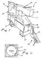
- FIG. 1is a front perspective view of an apparatus for measuring accommodation of a lens in an eye.
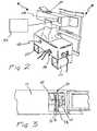
- FIG. 2is a rear perspective view of the apparatus of FIG. 1 .
- FIG. 3is a top plan view of a viewable target of the apparatus of FIG. 1 .
- FIG. 3Ais a top plan view of the housing of the apparatus of FIG. 1 illustrating the general position of a mirror and a lens.
- FIG. 4is a schematic diagram of the apparatus of FIG. 1 .
- FIG. 5is a schematic diagram of some features used in measuring accommodation of a lens.
- FIG. 6is a view of an image of a target in the apparatus of FIG. 1 .
- an apparatus 10 for measuring accommodation of a lens in an eyehas a housing 12 , a support structure 14 , and a base 16 .
- Apparatus 10is a self-contained apparatus that is compact and easily useable.
- apparatus 10is sized to fit on relatively small surfaces, such as a table top or the like.
- One or more spacers 54may be provided to adjust the height of apparatus 10 .
- apparatus 10may be used to determine the accommodation of any lens in an eye, including natural lenses, and implanted intraocular lenses. Because of its relatively compact size and its ease of use, apparatus 10 may be used in clinical settings, such as physician's offices or medical clinics, or may be used in businesses that are not necessarily medical businesses.
- the apparatusmay provide a convenient way for consumers to test their vision while they are at a store. Among other things, providing consumer self-tests should provide a substantial improvement of preventative medicine regarding the eye, and should reduce costs associated with preventative medicine.
- Apparatus 10is illustrated as having a fixation device 18 that is structured and positioned with respect to apparatus 10 to maintain a subject's eye in a relatively fixed position, as described herein.
- Fixation device 18is illustrated as having a chin rest, and a forehead rest, and a frame that is attached to base 16 .
- other fixation devicesmay only have a chin rest, a forehead rest, or other similar structure that maintains a fixed position of the subject's head while the subject is performing the procedure of measuring accommodation of a lens in his eye.
- Apparatus 10also includes one or more adjustment devices 48 which control the coarse positioning of a viewing aperture 20 in housing 12 .
- adjustment devices 48are knobs that can be rotated to adjust the position of viewing aperture 20 with respect to the position of fixation device 18 .
- Housing 12 of apparatus 10is illustrated as having a plurality of apertures opening into the housing.
- a viewing aperture 20is provided to permit a subject to view a target located in housing 12 , as discussed herein;
- a target access aperture 22is provided to permit access to the target in the housing;
- a instrument aperture 28is provided to permit one or more additional instruments to be operably connected to apparatus 10 to make measurements of the subject's eye.
- the aperturesare illustrated in relatively particular positions, the apertures may be provided in different positions and/or orientations.
- viewing aperture 20may be provided along the central optical axis of the lens, discussed herein, to provide a linear view of the target by the subject.
- target access aperturecan be provided at any position along housing 20 to permit a user to access and physically manipulate the target located in the housing.
- instrumentation aperture 28can be omitted if desired.
- Apparatus 10is also shown as including at least one controller 24 that controls the operation of apparatus 10 .
- Controller 24includes one or more controller keys 46 , and a display 56 , such as a liquid crystal display (LCD).
- Controller 24is in communication or is operably coupled with apparatus 10 via one or more cables that connect to one or more controller ports 26 , as shown in FIG. 2 . Any conventional cables and ports may be used.
- controller ports 26are BNC connectors.
- Apparatus 10may include a plurality of controllers 24 . For example, one controller may be provided that controls parameters such as target brightness, target speed, and the like, and a second controller may be provided that starts and stops the target from moving. Either, or both, controllers may be sized to fit within a person's hand so that either controller may be held by the subject viewing the target.
- Apparatus 10is provided with a computer that measures the accommodation amplitude of a lens in an eye of a subject.
- the computermay be provided in controller 24 , or may be provided in housing 12 , support structure 14 , or base 16 . In the illustrated embodiment of apparatus 10 , a computer is provided in controller 24 .
- controller keys 46a user can access multiple menus and select desired operations or parameters for testing.
- the usercan calibrate the apparatus, can reset the “near” position of the target so that the target returns to the closest stimulus position (e.g., the high diopter setting); can reset the “far” position of the target so that the target returns to the farthest stimulus position (e.g., the low diopter setting), can start and/or stop the movement of the target; can control the brightness of the target, the rate at which the target moves, and any offset of the stimulus.
- the computercan monitor the distance that the target moves, and determine the accommodative amplitude based on the distance, as discussed herein.
- FIGS. 3 and 3Aillustrate elements of apparatus 10 provided in housing 12 .
- a target 32is illustrated as being located on a track 40 .
- Track 40extends along the length of housing 12 so that target 32 can move within housing 12 towards two ends of housing 12 .
- Track 40may have a plurality of increments that allow target 32 to incrementally move along track 40 .
- track 40includes a threaded rod; however, in other apparatus, track 40 may include a plurality of notches disposed along the length of the track, or may include one or more switches that provide starting and stopping points of target 32 as it moves along track 40 .
- Target 32is illustrated as having an image 34 , a translucent member 36 , and an illumination source 38 .
- Target 32is coupled to a drive mechanism 44 , which causes target 32 to move along track 40 .
- Drive mechanism 44is operative coupled to a computer, as described above.
- Image 34is illustrated as being a slide, such as a 35 mm slide used in conventional photography.
- Translucent member 36is illustrated as a white sheet located between image 34 and illumination source 38 .
- Illumination source 38is illustrated as a lighted panel, for example, a panel having a plurality of light emitting diodes (LEDs).
- Illumination source 38provides a substantially uniform level of light, such as white light, that is transmitted through translucent member 36 and image 34 .
- Translucent member 36is structured to permit light to pass through the background, thus, translucent member is also understood to be a light transmitting member.
- Translucent member 36preferably is not transparent.
- Image 34is a physical object, such as a 35 mm slide, and contains an opaque region or opaque portion (e.g., a region that does not permit light to pass therethrough), and a non-opaque region or portion (e.g., a region that allows light to pass therethrough).
- the opaque regionoccupies a minor portion of the area of the image, or the target, and the non-opaque region occupies a major portion of the area of the image, or target.
- the term “minor portion”refers to less than 50%. In one embodiment, the opaque region is less than 20% of the area of the image, and in another embodiment, the opaque region is less than 10% of the area of the image.
- target 32includes an image that is disposed on a light-colored background.
- the light-colored backgroundis white.
- Providing an opaque region that occupies less than 50% of the area of the imagefacilitates controlling the dilation of the pupil of the subject's eye.
- Target 32is configured so that the dilation of the pupil of the subject's eye is substantially constant during the test procedure. Maintaining a relatively constant pupil size is achieved by providing a target having a relatively large bright background, which causes the pupil to contract.
- the brightness of the targetcan be controlled to provide the desired amount of pupil contraction or dilation for the particular subject being tested.
- the brightness of the targetcan be controlled to provide the desired amount of pupil dilation for a particular age range of subjects.
- target 32may be an assembly having an LED panel, a translucent member, and an image
- target 32may be an LCD screen capable of displaying different images, such as an LCD screen associated with video recorders.
- target 32may also include an illumination source that is structured to provide relatively even level of brightness and thereby eliminating the need for a separate translucent background.
- FIG. 3Aillustrates the general positions of a lens 42 and a mirror 30 located in housing 12 .
- lens 42is positioned between viewing aperture 20 and target 32 .
- Lens 42is structured to maintain a substantially constant image size of the target image 34 as target 32 moves along track 40 .
- Lens 42is a Badal lens.
- apparatus 10in contrast to the system disclosed in U.S. Pat. No. 4,778,268, includes a single lens disposed between the viewing aperture 20 and target 32 .
- Mirror 30is positioned in proximity to viewing aperture 20 to enable a subject to view an image of target image 34 as it reflects off of mirror 30 .
- Mirror 30is oriented in housing 12 so that the subject can view target image 34 when the subject is not viewing the target image 34 along the optical axis 62 (as shown in FIGS. 4 and 5) of lens 42 .
- mirror 30is oriented so that a subject may view target image 34 at an approximately ninety degree angle with respect to optical axis 62 of lens 42 .
- mirror 30is oriented at approximately forty-five degrees with respect to the length of housing 12 or central optical axis 62 .
- FIG. 5illustrates various parameters used in measuring the accommodation of a lens in a subject's eye.
- sis the target
- Dis the equivalent stimulus diopter
- fis the focal length of the lens
- Equation Iis programmed into a computer provided with apparatus 10 . Details of the Badal principle are well known, and can be found in “The Eye and Visual Optical Instruments”, Smith and Atchinson, Cambridge University Press, chapter 30, 1997, which is incorporated by reference herein.
- FIG. 6illustrates a virtual image 50 as seen by a subject looking through viewing aperture 20 .
- Virtual image 50has an opaque region 58 and a non-opaque region 60 .
- opaque region 58occupies a minor portion of the area of the image
- non-opaque regionoccupies a major portion of the area of the image. This relationship contributes to the apparatus' ability to maintain a relatively constant pupil size of the subject when he is viewing the image.
- the opaque region of target image 34should be relatively simple, and sharp to permit a subject to reliably determine when the image begins to blur or become focused.
- a computer of apparatus 10is generally pre-programmed to measure the equivalent of either positive-relative or negative relative accommodation amplitudes.
- the computermay be operated by pressing any number of keys 46 provided on controller 24 , as discussed above.
- the keyscause a menu, with one or more submenus, to be displayed on display 56 . Instructions for performing the test may also be displayed on the display.
- the user of apparatus 10can select either test, or a combination of tests.
- An operatorwhich may be the subject taking the test, begins a test when the image is in focus by pressing a key 46 that starts the test. The subject may then press a key 46 to stop the test when the image viewed by the subject begins to blur. This test is the positive-relative test.
- the imageis first blurred when the scan is started, and the subject presses a stop key when the image becomes focused.
- the computermay then determine the accommodative amplitude in diopters based on the distance the target moved from the start of the test to the end of the test.
- the accommodative amplitudeis the reciprocal of the distance the target moved. It is preferable for the subject to repeat the tests multiple times using the same criteria for blurred and focused images to provide an average with consistent results.
- the measurement erroris low, for example, the error is typically less than 0.25 diopters with a three diopter stimulus. Lower errors (e.g., errors lower than 0.20 diopters, and lower than 0.10 diopters) are also obtainable with the apparatus.
- a method for measuring accommodation of a lens, including implanted intraocular lenses, in an eye of a subjectincludes the steps of moving a target, which is structured to maintain a relatively constant pupil size in an eye of the subject viewing the target, from a first position towards or away from the subject's eye to a second position; determining the distance between the first position and the second position; and determining an accommodative amplitude of the lens in the eye of the subject based on the distance so determined.
- the movement of the targetmay be controlled by the subject viewing the target, and may be controlled by the subject without assistance from another person.
- the subjectmay control the movement of the target by using one or more of the controllers described hereinabove.
- the methodmay also include a step of illuminating an image provided on the target that is opaque and occupies a minor portion of the area of the target.
- the resultsmay be used to determine if the accommodative amplitude is sufficient to improve the vision of the subject.
- the methodmay be practiced to compare accommodative abilities of different intraocular lenses, and thereby provide the ability to select the best fit intraocular lens for a particular patient.
- Apparatus 10also includes an instrumentation aperture 28 , which permits one or more additional ophthalmic instruments to be connected to apparatus 10 .
- Instrumentation aperture 28is shown as being located on the opposite side of housing 12 with respect to viewing aperture 20 .
- mirror 30is positioned between viewing aperture 20 and instrumentation aperture 28 , it is preferable to use a “cold mirror” which allows infrared energy to pass through the mirror.
- apparatus 10may also include an ophthalmic instrument positioned so that infrared energy may be emitted from the ophthalmic instrument and pass through instrumentation aperture 28 to the subject's eye. The use of infrared energy permits additional measurements of the subject's eye without interfering with the subject's visual test of viewing the target in apparatus 10 .
- ophthalmic instrumentsinclude, and are not limited to, power refractors, and partial coherence interferometers.
- the length of housing 12is approximately 385 mm
- the widthis approximately 60 mm
- the height of housing 12is approximately 60 mm.
- the target 32 within such a housingis approximately 40 mm wide by 40 mm high.
- the housing 12is positioned with respect to an eye of a subject so that the optical axis of lens 42 is about 105 mm from the subject's eye, and the viewing aperture 20 is about 65 mm from the subject's eye.
- the Badal lenshas about a 160 mm focal length, and the lens is positioned about 160 mm (or one focal length) away from mirror 30 .
- some settingsmay include a high diopter setting of +5.5 diopters, a low diopter setting of ⁇ 0.5 diopters, a scan speed of about 0.30 diopters per second, a brightness level of 6, and an offset of 0.0 diopters.
Landscapes
- Life Sciences & Earth Sciences (AREA)
- Health & Medical Sciences (AREA)
- Medical Informatics (AREA)
- Biophysics (AREA)
- Ophthalmology & Optometry (AREA)
- Engineering & Computer Science (AREA)
- Biomedical Technology (AREA)
- Heart & Thoracic Surgery (AREA)
- Physics & Mathematics (AREA)
- Molecular Biology (AREA)
- Surgery (AREA)
- Animal Behavior & Ethology (AREA)
- General Health & Medical Sciences (AREA)
- Public Health (AREA)
- Veterinary Medicine (AREA)
- Eye Examination Apparatus (AREA)
Abstract
Description
Claims (28)
Priority Applications (1)
| Application Number | Priority Date | Filing Date | Title |
|---|---|---|---|
| US10/234,592US6739722B2 (en) | 2002-09-04 | 2002-09-04 | Apparatus and methods for measuring accommodation of a lens in an eye |
Applications Claiming Priority (1)
| Application Number | Priority Date | Filing Date | Title |
|---|---|---|---|
| US10/234,592US6739722B2 (en) | 2002-09-04 | 2002-09-04 | Apparatus and methods for measuring accommodation of a lens in an eye |
Publications (2)
| Publication Number | Publication Date |
|---|---|
| US20040041980A1 US20040041980A1 (en) | 2004-03-04 |
| US6739722B2true US6739722B2 (en) | 2004-05-25 |
Family
ID=31977433
Family Applications (1)
| Application Number | Title | Priority Date | Filing Date |
|---|---|---|---|
| US10/234,592Expired - LifetimeUS6739722B2 (en) | 2002-09-04 | 2002-09-04 | Apparatus and methods for measuring accommodation of a lens in an eye |
Country Status (1)
| Country | Link |
|---|---|
| US (1) | US6739722B2 (en) |
Cited By (13)
| Publication number | Priority date | Publication date | Assignee | Title |
|---|---|---|---|---|
| US20050122474A1 (en)* | 2003-12-04 | 2005-06-09 | Koretz Jane F. | Apparatus and method for accommodative stimulation of an eye and simultaneous ipsilateral accommodative imaging |
| US20070185574A1 (en)* | 2001-08-21 | 2007-08-09 | Yehoshua Ben Nun | Accommodating lens assembly |
| US20070244561A1 (en)* | 2004-10-13 | 2007-10-18 | Nulens Ltd. | Accommodating Intraocular Lens (Aiol), and Aiol Assemblies Including Same |
| US20080300680A1 (en)* | 2005-03-30 | 2008-12-04 | Nulens Ltd | Accommodating Intraocular Lens (Aiol) and Discrete Components Therefor |
| US20090198247A1 (en)* | 2006-08-25 | 2009-08-06 | Nulens Ltd. | Intraocular lens implantation kit |
| US20100121444A1 (en)* | 2007-03-05 | 2010-05-13 | Nulens Ltd. | Unitary Accommodating Intraocular Lenses (AIOLs) and Discrete Base Members For Use Therewith |
| US7842087B2 (en) | 2004-04-29 | 2010-11-30 | Nulens Ltd. | Accommodating intraocular lens assemblies and accommodation measurement implant |
| US20110112636A1 (en)* | 2008-07-24 | 2011-05-12 | Joshua Ben Nun | Accommodating Intraocular Lens (AIOL) Capsules |
| USD702346S1 (en) | 2007-03-05 | 2014-04-08 | Nulens Ltd. | Haptic end plate for use in an intraocular assembly |
| US8931900B2 (en) | 2012-10-18 | 2015-01-13 | Bausch & Lomb Incorporated | Method and apparatus for determining depth of focus of an eye optical system |
| US10321818B2 (en) | 2016-10-31 | 2019-06-18 | Brainscope Company, Inc. | System and method for ocular function tests |
| US10687936B2 (en) | 2016-05-22 | 2020-06-23 | Rayner Intraocular Lenses Limited | Hybrid accommodating intraocular lens assemblages |
| US11224505B2 (en) | 2018-11-02 | 2022-01-18 | Rayner Intraocular Lenses Limited | Hybrid accommodating intraocular lens assemblages including discrete lens unit with segmented lens haptics |
Families Citing this family (13)
| Publication number | Priority date | Publication date | Assignee | Title |
|---|---|---|---|---|
| US7073193B2 (en)* | 2002-04-16 | 2006-07-04 | Microsoft Corporation | Media content descriptions |
| US7640563B2 (en)* | 2002-04-16 | 2009-12-29 | Microsoft Corporation | Describing media content in terms of degrees |
| US7617511B2 (en)* | 2002-05-31 | 2009-11-10 | Microsoft Corporation | Entering programming preferences while browsing an electronic programming guide |
| US20030225777A1 (en)* | 2002-05-31 | 2003-12-04 | Marsh David J. | Scoring and recommending media content based on user preferences |
| US7836466B2 (en)* | 2002-06-06 | 2010-11-16 | Microsoft Corporation | Methods and systems for generating electronic program guides |
| US20040001081A1 (en)* | 2002-06-19 | 2004-01-01 | Marsh David J. | Methods and systems for enhancing electronic program guides |
| GB0421215D0 (en)* | 2004-09-23 | 2004-10-27 | Procyon Instr Ltd | Pupillometers |
| US20070154523A1 (en)* | 2005-12-30 | 2007-07-05 | Rick Lewis | Controlled pupil dilation for diagnostic and treatment of visual anomalies |
| US7963654B2 (en)* | 2006-10-16 | 2011-06-21 | Karan Aggarwala | Apparatus and method for subjective determination of the refractive error of the eye |
| ES2327704B1 (en)* | 2008-04-30 | 2010-08-30 | Universitat Politecnica De Catalunya | METHOD AND SYSTEM FOR THE OBJECTIVE MEASURE OF EYE ACCOMMODATION. |
| JP7728741B2 (en)* | 2019-07-05 | 2025-08-25 | エシロール・アンテルナシオナル | Method for inducing controlled changes in accommodation in a subject's eye - Patent Application 20070122997 |
| CN114296258A (en)* | 2021-12-30 | 2022-04-08 | 汕头大学·香港中文大学联合汕头国际眼科中心 | Device for assisting in fixing spectroscope outside glasses |
| ES2990046A1 (en)* | 2023-05-24 | 2024-11-28 | Univ Madrid Complutense | Device for objective measurement of accommodation (Machine-translation by Google Translate, not legally binding) |
Citations (15)
| Publication number | Priority date | Publication date | Assignee | Title |
|---|---|---|---|---|
| US4105302A (en)* | 1976-06-23 | 1978-08-08 | Tate Jr George W | Automatic refraction apparatus and method |
| US4408846A (en) | 1981-02-02 | 1983-10-11 | Andrew M. Clay | Method and apparatus for increasing visual acuity |
| US4533221A (en) | 1983-01-25 | 1985-08-06 | Trachtman Joseph N | Methods and apparatus for accommodation training |
| US4660945A (en) | 1983-01-25 | 1987-04-28 | Trachtman Joseph N | Methods and apparatus for accommodation training |
| US4778268A (en) | 1983-08-26 | 1988-10-18 | The United States Of America As Represented By The Administrator Of The National Aeronautics And Space Administration | Visual accommodation trainer-tester |
| US4838677A (en) | 1987-04-06 | 1989-06-13 | Ayetech Inc. | Eye exercising devices |
| US4943151A (en) | 1989-06-23 | 1990-07-24 | The United States Of America As Represented By The Secretary Of The Navy | Scheiner-principle vernier optometer |
| US5223866A (en) | 1991-12-30 | 1993-06-29 | The United States Of America As Represented By The Secretary Of The Navy | Small, simple and cost-effective scheiner-principle optometer with computer interface for automated assessment |
| US5374193A (en) | 1983-01-25 | 1994-12-20 | Trachtman; Joseph N. | Methods and apparatus for use in alpha training, EMG training and dichotic learning |
| US5450145A (en) | 1992-11-04 | 1995-09-12 | Valentine; James M. | Apparatus and method for testing visual focus control |
| US5828439A (en)* | 1995-11-15 | 1998-10-27 | Nikon Corporation | Ophthalmologic device for measuring eye refractive power |
| US6033073A (en) | 1997-08-15 | 2000-03-07 | Potapova; Olga | Visual training system and apparatus for vision correction, especially for various forms of strabismus ("crossed" eyes) |
| US6249589B1 (en) | 1994-04-21 | 2001-06-19 | Bodenseewerk Geratetechnik Gmbh | Device for passive friend-or-foe discrimination |
| US6382795B1 (en) | 2000-05-20 | 2002-05-07 | Carl Zeiss, Inc. | Method and apparatus for measuring refractive errors of an eye |
| US6575572B2 (en)* | 2001-09-21 | 2003-06-10 | Carl Zeiss Ophthalmic Systems, Inc. | Method and apparatus for measuring optical aberrations of an eye |
- 2002
- 2002-09-04USUS10/234,592patent/US6739722B2/ennot_activeExpired - Lifetime
Patent Citations (15)
| Publication number | Priority date | Publication date | Assignee | Title |
|---|---|---|---|---|
| US4105302A (en)* | 1976-06-23 | 1978-08-08 | Tate Jr George W | Automatic refraction apparatus and method |
| US4408846A (en) | 1981-02-02 | 1983-10-11 | Andrew M. Clay | Method and apparatus for increasing visual acuity |
| US5374193A (en) | 1983-01-25 | 1994-12-20 | Trachtman; Joseph N. | Methods and apparatus for use in alpha training, EMG training and dichotic learning |
| US4533221A (en) | 1983-01-25 | 1985-08-06 | Trachtman Joseph N | Methods and apparatus for accommodation training |
| US4660945A (en) | 1983-01-25 | 1987-04-28 | Trachtman Joseph N | Methods and apparatus for accommodation training |
| US4778268A (en) | 1983-08-26 | 1988-10-18 | The United States Of America As Represented By The Administrator Of The National Aeronautics And Space Administration | Visual accommodation trainer-tester |
| US4838677A (en) | 1987-04-06 | 1989-06-13 | Ayetech Inc. | Eye exercising devices |
| US4943151A (en) | 1989-06-23 | 1990-07-24 | The United States Of America As Represented By The Secretary Of The Navy | Scheiner-principle vernier optometer |
| US5223866A (en) | 1991-12-30 | 1993-06-29 | The United States Of America As Represented By The Secretary Of The Navy | Small, simple and cost-effective scheiner-principle optometer with computer interface for automated assessment |
| US5450145A (en) | 1992-11-04 | 1995-09-12 | Valentine; James M. | Apparatus and method for testing visual focus control |
| US6249589B1 (en) | 1994-04-21 | 2001-06-19 | Bodenseewerk Geratetechnik Gmbh | Device for passive friend-or-foe discrimination |
| US5828439A (en)* | 1995-11-15 | 1998-10-27 | Nikon Corporation | Ophthalmologic device for measuring eye refractive power |
| US6033073A (en) | 1997-08-15 | 2000-03-07 | Potapova; Olga | Visual training system and apparatus for vision correction, especially for various forms of strabismus ("crossed" eyes) |
| US6382795B1 (en) | 2000-05-20 | 2002-05-07 | Carl Zeiss, Inc. | Method and apparatus for measuring refractive errors of an eye |
| US6575572B2 (en)* | 2001-09-21 | 2003-06-10 | Carl Zeiss Ophthalmic Systems, Inc. | Method and apparatus for measuring optical aberrations of an eye |
Cited By (33)
| Publication number | Priority date | Publication date | Assignee | Title |
|---|---|---|---|---|
| US20070185574A1 (en)* | 2001-08-21 | 2007-08-09 | Yehoshua Ben Nun | Accommodating lens assembly |
| US8382831B2 (en) | 2001-08-21 | 2013-02-26 | Nulens Ltd. | Method and apparatus for anchoring an intraocular lens assembly |
| US7998199B2 (en) | 2001-08-21 | 2011-08-16 | Nulens, Ltd. | Method of anchoring an accommodating intraocular lens assembly |
| US20110082544A1 (en)* | 2001-08-21 | 2011-04-07 | Nulens Ltd. | Accommodating lens assembly |
| US7854764B2 (en) | 2001-08-21 | 2010-12-21 | Nulens Ltd. | Accommodating lens assembly |
| US20050122474A1 (en)* | 2003-12-04 | 2005-06-09 | Koretz Jane F. | Apparatus and method for accommodative stimulation of an eye and simultaneous ipsilateral accommodative imaging |
| US7070276B2 (en)* | 2003-12-04 | 2006-07-04 | Rensselaer Polytechnic Institute | Apparatus and method for accommodative stimulation of an eye and simultaneous ipsilateral accommodative imaging |
| US7842087B2 (en) | 2004-04-29 | 2010-11-30 | Nulens Ltd. | Accommodating intraocular lens assemblies and accommodation measurement implant |
| US20110112635A1 (en)* | 2004-04-29 | 2011-05-12 | Nulens Ltd. | Accommodating intraocular lens measurement implant |
| US12076229B2 (en) | 2004-04-29 | 2024-09-03 | Forsight Vision6, Inc. | Accommodating intraocular lens assemblies and accommodation measurement implant |
| US20110035002A1 (en)* | 2004-04-29 | 2011-02-10 | Nulens Ltd. | Accommodating intraocular lens assemblies and accommodation measurement implant |
| US8956409B2 (en) | 2004-04-29 | 2015-02-17 | Nulens Ltd. | Accommodating intraocular lens assemblies and accommodation measurement implant |
| US10912643B2 (en) | 2004-04-29 | 2021-02-09 | Forsight Vision6, Inc. | Accommodating intraocular lens assemblies and accommodation measurement implant |
| US7815678B2 (en) | 2004-10-13 | 2010-10-19 | Nulens Ltd. | Accommodating intraocular lens (AIOL), and AIOL assemblies including same |
| US20070244561A1 (en)* | 2004-10-13 | 2007-10-18 | Nulens Ltd. | Accommodating Intraocular Lens (Aiol), and Aiol Assemblies Including Same |
| US12036110B2 (en) | 2005-03-30 | 2024-07-16 | Forsight Vision6, Inc. | Accommodating intraocular lens (AIOL) assemblies, and discrete components therefor |
| US20080300680A1 (en)* | 2005-03-30 | 2008-12-04 | Nulens Ltd | Accommodating Intraocular Lens (Aiol) and Discrete Components Therefor |
| US8834565B2 (en) | 2005-03-30 | 2014-09-16 | Nulens Ltd. | Foldable accommodating intraocular lens |
| US10966818B2 (en) | 2005-03-30 | 2021-04-06 | Forsight Vision6, Inc. | Accommodating intraocular lens (AIOL) assemblies, and discrete components therefor |
| US9814568B2 (en) | 2005-03-30 | 2017-11-14 | Forsight Vision6, Inc. | Accommodating intraocular lens having dual shape memory optical elements |
| US10166096B2 (en) | 2005-03-30 | 2019-01-01 | Forsight Vision6, Inc. | Foldable accommodating intraocular lens |
| US20090198247A1 (en)* | 2006-08-25 | 2009-08-06 | Nulens Ltd. | Intraocular lens implantation kit |
| US8273123B2 (en) | 2007-03-05 | 2012-09-25 | Nulens Ltd. | Unitary accommodating intraocular lenses (AIOLs) and discrete base members for use therewith |
| USD702346S1 (en) | 2007-03-05 | 2014-04-08 | Nulens Ltd. | Haptic end plate for use in an intraocular assembly |
| US20100121444A1 (en)* | 2007-03-05 | 2010-05-13 | Nulens Ltd. | Unitary Accommodating Intraocular Lenses (AIOLs) and Discrete Base Members For Use Therewith |
| US8398709B2 (en) | 2008-07-24 | 2013-03-19 | Nulens Ltd. | Accommodating intraocular lens (AIOL) capsules |
| US20110112636A1 (en)* | 2008-07-24 | 2011-05-12 | Joshua Ben Nun | Accommodating Intraocular Lens (AIOL) Capsules |
| US8931900B2 (en) | 2012-10-18 | 2015-01-13 | Bausch & Lomb Incorporated | Method and apparatus for determining depth of focus of an eye optical system |
| US11589980B2 (en) | 2016-05-22 | 2023-02-28 | Rayner Intraocular Lenses Limited | Hybrid accommodating intraocular lens assemblages |
| US10687936B2 (en) | 2016-05-22 | 2020-06-23 | Rayner Intraocular Lenses Limited | Hybrid accommodating intraocular lens assemblages |
| US10881290B2 (en) | 2016-10-31 | 2021-01-05 | Brainscope Company, Inc. | System and method for ocular function tests |
| US10321818B2 (en) | 2016-10-31 | 2019-06-18 | Brainscope Company, Inc. | System and method for ocular function tests |
| US11224505B2 (en) | 2018-11-02 | 2022-01-18 | Rayner Intraocular Lenses Limited | Hybrid accommodating intraocular lens assemblages including discrete lens unit with segmented lens haptics |
Also Published As
| Publication number | Publication date |
|---|---|
| US20040041980A1 (en) | 2004-03-04 |
Similar Documents
| Publication | Publication Date | Title |
|---|---|---|
| US6739722B2 (en) | Apparatus and methods for measuring accommodation of a lens in an eye | |
| US5094521A (en) | Apparatus for evaluating eye alignment | |
| US7275823B2 (en) | Optometric device | |
| US7370964B2 (en) | Measuring refractive characteristics of human eyes | |
| EP1791462B1 (en) | Pupillometer | |
| TW202015613A (en) | Fundus camera and method for self-shooting fundus | |
| US9572486B2 (en) | Device and method for checking human vision | |
| CN104042186A (en) | Self-service type eye comprehensive detection device | |
| EP1426006B1 (en) | Ophthalmologic apparatus | |
| KR20140134659A (en) | A refractometer with a comparative vision correction simulator | |
| JP2017124173A (en) | Optometry system and optometry method | |
| WO2000032086A1 (en) | An instrument and a method for measuring the aberration of human eyes | |
| JPH06285026A (en) | Ophthalmologic apparatus | |
| US5650839A (en) | Retinoscope assembly with scale | |
| JP7249097B2 (en) | Ophthalmic device and optometric system | |
| JPS6144014B2 (en) | ||
| JP2022000168A (en) | Ophthalmologic device | |
| JPH03215243A (en) | Eyeballs movement analyzer | |
| KR20070043836A (en) | Ophthalmic device | |
| CN219206895U (en) | Adjustable operation table of shadow checking and optometry device | |
| US20250194917A1 (en) | Device for eyesight examination, in particular for performing field of vision tests | |
| JPH06304140A (en) | Optometry device | |
| SU1680056A1 (en) | Device for examining the vision field | |
| WO2024121350A1 (en) | Apparatus and method for determining refraction error of at least an eye of a subject | |
| Decker et al. | A semi-automated instrument for determination of acuity threshold |
Legal Events
| Date | Code | Title | Description |
|---|---|---|---|
| AS | Assignment | Owner name:ADVANCED MEDICAL OPTICS, INC., CALIFORNIA Free format text:ASSIGNMENT OF ASSIGNORS INTEREST;ASSIGNORS:LANG, ALAN J.;LAGUETTE, STEPEN W.;REEL/FRAME:013581/0742 Effective date:20020829 | |
| AS | Assignment | Owner name:ADVANCED MEDICAL OPTICS, INC., CALIFORNIA Free format text:ASSIGNMENT OF ASSIGNORS INTEREST;ASSIGNORS:SCHIER, ALAN;ASA, JOSEPH WARREN;REEL/FRAME:013551/0196 Effective date:20021031 | |
| STCF | Information on status: patent grant | Free format text:PATENTED CASE | |
| AS | Assignment | Owner name:BANK OF AMERICA, N.A., AS ADMINISTRATIVE AGENT, CA Free format text:SECURITY AGREEMENT;ASSIGNOR:ADVANCED MEDICAL OPTICS, INC.;REEL/FRAME:014910/0546 Effective date:20040625 | |
| AS | Assignment | Owner name:ADVANCED MEDICAL OPTICS, INC., CALIFORNIA Free format text:RELEASE OF SECURITY INTEREST AT REEL/FRAME NO. 14910/0546;ASSIGNOR:BANK OF AMERICA, N.A.;REEL/FRAME:019111/0582 Effective date:20070402 | |
| AS | Assignment | Owner name:BANK OF AMERICA, N.A., AS ADMINISTRATIVE AGENT,NOR Free format text:INTELLECTUAL PROPERTY SECURITY AGREEMENT;ASSIGNOR:ADVANCED MEDICAL OPTICS, INC.;REEL/FRAME:019501/0069 Effective date:20070402 Owner name:BANK OF AMERICA, N.A., AS ADMINISTRATIVE AGENT, NORTH CAROLINA Free format text:INTELLECTUAL PROPERTY SECURITY AGREEMENT;ASSIGNOR:ADVANCED MEDICAL OPTICS, INC.;REEL/FRAME:019501/0069 Effective date:20070402 Owner name:BANK OF AMERICA, N.A., AS ADMINISTRATIVE AGENT, NO Free format text:INTELLECTUAL PROPERTY SECURITY AGREEMENT;ASSIGNOR:ADVANCED MEDICAL OPTICS, INC.;REEL/FRAME:019501/0069 Effective date:20070402 | |
| FPAY | Fee payment | Year of fee payment:4 | |
| REMI | Maintenance fee reminder mailed | ||
| AS | Assignment | Owner name:ADVANCED MEDICAL OPTICS, INC., CALIFORNIA Free format text:RELEASE BY SECURED PARTY;ASSIGNOR:BANK OF AMERICA, N.A. AS ADMINISTRATIVE AGENT;REEL/FRAME:022320/0427 Effective date:20090225 Owner name:ADVANCED MEDICAL OPTICS, INC.,CALIFORNIA Free format text:RELEASE BY SECURED PARTY;ASSIGNOR:BANK OF AMERICA, N.A. AS ADMINISTRATIVE AGENT;REEL/FRAME:022320/0427 Effective date:20090225 | |
| AS | Assignment | Owner name:ABBOTT MEDICAL OPTICS INC., CALIFORNIA Free format text:MERGER;ASSIGNOR:ADVANCED MEDICAL OPTICS, INC.;REEL/FRAME:023234/0277 Effective date:20090226 Owner name:ABBOTT MEDICAL OPTICS INC.,CALIFORNIA Free format text:MERGER;ASSIGNOR:ADVANCED MEDICAL OPTICS, INC.;REEL/FRAME:023234/0277 Effective date:20090226 | |
| FPAY | Fee payment | Year of fee payment:8 | |
| FPAY | Fee payment | Year of fee payment:12 | |
| AS | Assignment | Owner name:JOHNSON & JOHNSON SURGICAL VISION, INC., CALIFORNI Free format text:CHANGE OF NAME;ASSIGNOR:ABBOTT MEDICAL OPTICS INC.;REEL/FRAME:047150/0821 Effective date:20180209 |